WO2017217519A1 - 化粧材及び化粧材の製造方法 - Google Patents
化粧材及び化粧材の製造方法 Download PDFInfo
- Publication number
- WO2017217519A1 WO2017217519A1 PCT/JP2017/022230 JP2017022230W WO2017217519A1 WO 2017217519 A1 WO2017217519 A1 WO 2017217519A1 JP 2017022230 W JP2017022230 W JP 2017022230W WO 2017217519 A1 WO2017217519 A1 WO 2017217519A1
- Authority
- WO
- WIPO (PCT)
- Prior art keywords
- resin layer
- foamed resin
- real part
- male
- layer
- Prior art date
- Legal status (The legal status is an assumption and is not a legal conclusion. Google has not performed a legal analysis and makes no representation as to the accuracy of the status listed.)
- Ceased
Links
Images



Classifications
-
- E—FIXED CONSTRUCTIONS
- E04—BUILDING
- E04F—FINISHING WORK ON BUILDINGS, e.g. STAIRS, FLOORS
- E04F15/00—Flooring
- E04F15/02—Flooring or floor layers composed of a number of similar elements
-
- E—FIXED CONSTRUCTIONS
- E04—BUILDING
- E04F—FINISHING WORK ON BUILDINGS, e.g. STAIRS, FLOORS
- E04F15/00—Flooring
- E04F15/02—Flooring or floor layers composed of a number of similar elements
- E04F15/02038—Flooring or floor layers composed of a number of similar elements characterised by tongue and groove connections between neighbouring flooring elements
-
- E—FIXED CONSTRUCTIONS
- E04—BUILDING
- E04F—FINISHING WORK ON BUILDINGS, e.g. STAIRS, FLOORS
- E04F15/00—Flooring
- E04F15/02—Flooring or floor layers composed of a number of similar elements
- E04F15/10—Flooring or floor layers composed of a number of similar elements of other materials, e.g. fibrous or chipped materials, organic plastics, magnesite tiles, hardboard, or with a top layer of other materials
-
- E—FIXED CONSTRUCTIONS
- E04—BUILDING
- E04F—FINISHING WORK ON BUILDINGS, e.g. STAIRS, FLOORS
- E04F15/00—Flooring
- E04F15/02—Flooring or floor layers composed of a number of similar elements
- E04F15/10—Flooring or floor layers composed of a number of similar elements of other materials, e.g. fibrous or chipped materials, organic plastics, magnesite tiles, hardboard, or with a top layer of other materials
- E04F15/107—Flooring or floor layers composed of a number of similar elements of other materials, e.g. fibrous or chipped materials, organic plastics, magnesite tiles, hardboard, or with a top layer of other materials composed of several layers, e.g. sandwich panels
-
- E—FIXED CONSTRUCTIONS
- E04—BUILDING
- E04F—FINISHING WORK ON BUILDINGS, e.g. STAIRS, FLOORS
- E04F15/00—Flooring
- E04F15/18—Separately-laid insulating layers; Other additional insulating measures; Floating floors
-
- E—FIXED CONSTRUCTIONS
- E04—BUILDING
- E04F—FINISHING WORK ON BUILDINGS, e.g. STAIRS, FLOORS
- E04F2201/00—Joining sheets or plates or panels
- E04F2201/02—Non-undercut connections, e.g. tongue and groove connections
- E04F2201/023—Non-undercut connections, e.g. tongue and groove connections with a continuous tongue or groove
Definitions
- the present invention relates to a decorative material and a method for manufacturing the decorative material.
- decorative materials for interior use are generally used in which surface decorative materials such as decorative sheets, decorative paper, veneer, etc. are bonded on a wooden substrate such as plywood, wood fiber board, composite substrate, etc. It has been. Since these interior decoration materials have low heat insulation performance, there is a problem that they feel cold when they are touched by hands or feet when the temperature is low in winter or the like. In addition, when using air conditioner cooling or heating indoors in summer or winter, a large amount of energy is required to cool or warm the indoor surface to the target temperature, resulting in high electricity costs. There is a problem.
- a building material composed of a laminated sheet in which a resin cross-linked foam, a skin material and a reinforcing material are laminated for example, refer to Patent Document 1
- a decorative material and a substrate having a substantially equal shape for example, a building material composed of a laminated sheet in which a resin cross-linked foam, a skin material and a reinforcing material are laminated
- Patent Document 2 a method for manufacturing a decorative floor material that adheres to the back surface of the decorative material while forming the protruding portion by shifting the decorative material in the longitudinal direction and the direction orthogonal to the longitudinal direction
- the building material described in Patent Document 1 has a problem that the impact resistance of the resin crosslinked foam is low and the scratch resistance is not sufficient.
- the side surface of the building material is provided with a fruit or chamfered, if the resin cross-linked foam is cut, the resin cross-linked foam is welded to the cutting blade, making it difficult to cut.
- the building material is applied to the floor surface as a flooring material, the resin cross-linked foams between the adjacent flooring materials are actually bonded to each other by walking on the floor surface. Rubbing and floor noise occur, and even when the above building materials are used as panel materials for walls and ceilings, the actual fitting is similar to floor materials due to the flow of indoor air and contact with objects and people.
- the resin cross-linked foams rub against each other at the joint, and a sound (smearing sound) similar to floor noise is generated.
- the decorative floor material manufactured by the manufacturing method of Patent Document 2 has not been sufficiently studied for a configuration for sufficiently exhibiting performance as a floor material such as heat insulation and suppression of floor noise. There is a problem that the performance is not sufficient.
- JP 2008-196213 A Japanese Examined Patent Publication No. 7-96209
- An object of the present invention is to provide a decorative material in which generation of floor noise and itchiness is suppressed, and a method for manufacturing the decorative material.
- the present inventors have made real processing on the non-foamed resin layer in the cosmetic material having the foamed resin layer and the non-foamed resin layer, and the male real part and the female real part. , And one male cosmetic material and another cosmetic material are inserted into the male real part and female real part, thereby generating floor squealing as a flooring material and itching sound as a panel material for walls and ceilings.
- the inventors have found that it is possible to suppress the occurrence of this, and have completed the present invention.
- the present invention comprises a foamed resin layer and a non-foamed resin layer and is a polygonal cosmetic material in plan view, wherein the non-foamed resin layer on at least one side of the polygon has a male part and the polygon A female real part capable of fitting the male part into the non-foamed resin layer on at least one other side of the male part, and a male real part of the one cosmetic material and a female real part of the other cosmetic material, Can be fitted in a state where the foamed resin layer of the one decorative material and the foamed resin layer of the other decorative material are not in contact with each other.
- the foamed resin layer of the one cosmetic material and the other cosmetic material is fitted with a gap of 10 mm or less.
- the decorative material of the present invention is arranged such that the side surface of the foamed resin layer below the male part is closer to the center side of the polygonal shape in plan view than the side surface of the non-foamed resin layer having the male part.
- the side surface of the foamed resin layer below the female real part is arranged to be closer to the center side of the polygonal shape in plan view than the side surface of the non-foamed resin layer having the female real part, or
- the side surface of the foamed resin layer below the male solid part and the side surface of the foamed resin layer below the female real part are both center sides of the polygonal shape in plan view from the side surface of the non-foamed resin layer. It is preferable that it is arranged to come to.
- the decorative material of the present invention is arranged such that the side surface of the foamed resin layer below the male part is closer to the center side of the polygonal shape in plan view than the side surface of the non-foamed resin layer having the male part.
- the side surface of the foamed resin layer below the female real part is arranged so as to be on the opposite side of the center side of the polygonal shape in plan view from the side surface of the non-foamed resin layer having the female real part,
- the distance between the side surface of the foamed resin layer below and the side surface of the non-foamed resin layer is preferably larger than the distance between the side surface of the foamed resin layer below the female real part and the side surface of the non-foamed resin layer.
- the side surface of the foamed resin layer below the male real part and the side surface of the non-foamed resin layer continuously form a surface
- the foamed resin layer below the female real part It is preferable that the side surface and the side surface of the non-foamed resin layer continuously form a surface.
- the present invention is a method for producing a polygonal decorative material comprising a foamed resin layer and a non-foamed resin layer, wherein the male part is formed on the non-foamed resin layer on at least one side of the polygon Forming a female real part capable of fitting the male real part into the non-foamed resin layer on at least one other side of the polygon, and forming the male real part and the female real part
- a step of attaching a foamed resin layer to the non-foamed resin layer and in the step of attaching the foamed resin layer to the non-foamed resin layer, the male part of the one cosmetic material and the female real part of the other cosmetic material
- the foamed resin layer is pasted at a position where the foamed resin layer of the one decorative material and the foamed resin layer of the other decorative material do not come into contact with each other. It is also a manufacturing method.
- the present invention is also a method for producing a polygonal decorative material comprising a foamed resin layer and a non-foamed resin layer, wherein the foamed resin layer is formed on the entire surface of one surface of the non-foamed resin layer.
- a female capable of forming a male part on at least one side of a polygon of the non-foamed resin layer on which the foamed resin layer is formed and fitting the male part on at least one other side of the polygon A step of forming a real part, and in the step of forming the male real part and the female real part, when the male real part of the one cosmetic material and the female real part of the other cosmetic material are fitted.
- the foamed resin layer below the male real part and the female real part is cut so that the foamed resin layer of the one decorative material and the foamed resin layer of the other decorative material do not contact each other.
- the decorative material of the present invention is a decorative material provided with a foamed resin layer and a non-foamed resin layer, wherein a real processing is applied to the non-foamed resin layer to form a male real part and a female real part, respectively.
- a decorative material can be manufactured by a method of applying a predetermined actual processing to the non-foamed resin layer and then sticking the non-foamed resin layer to the non-foamed resin layer while highly controlling the position of the foamed resin layer.
- the non-foamed resin layer and the foamed resin layer are attached, the non-foamed resin layer is subjected to predetermined actual processing, and at the same time, the foamed resin layer is cut.
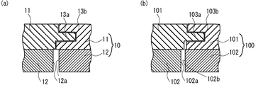
- (A) is a schematic diagram which shows the cross section of a preferable example of the decorative material of this invention
- (b) is a schematic diagram which shows the cross section of another preferable example of the decorative material of this invention.
- (A) is a schematic diagram which shows the cross section of a preferable example of the decorative material of this invention
- (b) is a schematic diagram which shows the cross section of another preferable example of the decorative material of this invention.
- (A) is a schematic diagram which shows the cross section of a preferable example of the decorative material of this invention
- (b) is a schematic diagram which shows the cross section of another preferable example of the decorative material of this invention.
- (A) is a schematic diagram showing a plane of a preferred example of the decorative material of the present invention shown in FIG.
- FIG. 1 (a), (b) is fitted with the decorative material of the present invention shown in (a). It is a schematic diagram which shows a state.
- (c) is the overload resistance test of the cosmetics which concern on an Example and a comparative example. It is a figure explaining.
- the decorative material of the present invention has a foamed resin layer and a non-foamed resin layer laminated on the foamed resin layer, and has a polygonal shape in plan view.
- the decorative material of the present invention has a polygonal shape in plan view, specifically, the polygon may have a shape such as a triangle, a quadrangle, or a pentagon as necessary, and is not particularly limited.
- the decorative material of the present invention is subjected to actual processing.
- the actual processing is not particularly limited, and may be known processing such as actual processing and phase matching processing.
- the real (sane) is, for example, in a shape that can be fitted to the side surface of a base material made of a wooden material such as a floor or a wall panel, as shown in FIG. It refers to the protrusions and groove-like recesses that are formed.
- the protrusion part 13a male solid part
- the groove-shaped recessed part 13b female real part of the shape which can be fitted in the protrusion part Is generally referred to as a real fruit
- a protrusion 23a male part
- the groove-shaped recessed part 23b female real part of the shape which can be fitted in
- the male and female provided in each of the adjacent several base material are fitted, and construction is carried out. can do.
- a male part is formed on the non-foamed resin layer on at least one side of the polygon, and the non-foamed resin layer on at least one other side of the polygon.
- a female real part capable of fitting the male real part is formed.
- the cosmetic material of the present invention includes the foamed resin layer of the one cosmetic material and the other when the male part of the one cosmetic material and the female real part of the other cosmetic material are fitted. The foamed resin layer of the decorative material does not come into contact.
- the foamed resin layer of the one cosmetic material and the other cosmetic material is fitted with a gap of 10 mm or less.
- the said clearance gap exceeds 10 mm, the heat insulation of the decorative member of this invention may fall, or intensity
- a more preferable upper limit of the gap is 6 mm.
- the side surface of the foamed resin layer below the male part is the male component. It is arranged so as to be closer to the center of the polygonal shape in plan view than the side surface of the non-foamed resin layer having the real part, or the side surface of the foamed resin layer below the female real part has the female real part.
- both the side surface of the foamed resin layer below the male real part and the side surface of the foamed resin layer below the female real part have a polygonal shape in plan view than the side surface of the non-foamed resin layer. It is preferable that they are arranged so as to come to the center side.
- Examples of the cosmetic material of the present invention having such an embodiment include the embodiment shown in FIG. 1A and the embodiment shown in FIG. That is, FIG. 1 (a) shows an example of a cross section of the decorative material of the present invention that has been subjected to actual processing, and FIG. 1 (b) illustrates a cross section of the decorative material of the present invention that has been subjected to actual processing. Another example is shown, FIG.
- FIG. 2 (a) shows an example of a cross section of the cosmetic material of the present invention that has undergone phase determination processing
- FIG. 2 (b) shows the cosmetic material of the present invention that has undergone phase determination processing.
- the decorative sheet for floor 10 of the present invention shown in FIG. 1A includes a non-foamed resin layer 11 (21) and a foamed resin layer 12 ( 22), a male solid part 13a (23a) is provided on one side of the non-foamed resin layer 11 (21), and a female real part 13b (23b) is provided on the other side.
- the non-foamed resin layer 11 has a side surface 12a (22a) on the center side (hereinafter also referred to as the inner side) of the polygonal shape in plan view with respect to the actual structure portion of the non-foamed resin layer 11 (21). (21) is pasted.
- 4 (a) is a plan view of the decorative material having the structure shown in FIG. 1 (a), and FIG. 4 (b) shows a state in which the decorative material of the present invention shown in (a) is fitted.
- FIG.4 (b) shows a schematic diagram, as shown in FIG.4 (b), the male real part 13b provided in one side of one makeup
- decoration material is the female real part 13b provided in one side of the other cosmetics.
- the decorative material of the present invention is fitted to each other by the fitting part 13c fitted in the foamed resin layer 12, but the foamed resin layers 12 are not in contact with each other, and floor noise does not occur.
- the decorative material of the present invention is disposed, for example, such that the side surface of the foamed resin layer below the male real part is located inside the side surface of the non-foamed resin layer having the male real part, and is below the female real part.
- the side surface of the foamed resin layer is arranged so as to be opposite to the center side of the polygonal shape in plan view (hereinafter also referred to as the outside) than the side surface of the non-foamed resin layer having the female real part.
- the distance between the side surface of the lower foamed resin layer and the side surface of the non-foamed resin layer is larger than the distance between the side surface of the lower foamed resin layer and the side surface of the non-foamed resin layer.
- the non-foamed resin layer 101 (201) as in the floor decorative plate 100 of the present invention shown in FIG. 1 (b) (the floor decorative plate 200 of the present invention shown in FIG. 2 (b)).
- the foamed resin layer 102 (202), the male part 103a (203a) is provided on one side of the non-foamed resin layer 101 (201), and the female part 103b (203b) is provided on the other side.
- the side surface 102a (202a) of the foamed resin layer 102 (202) below the male real part 103a (203a) is disposed inside the side surface of the non-foamed resin layer 101 (201), and the female real part 103b
- the side surface 102b (202b) of the foamed resin layer 102 (202) below (203b) is disposed outside the side surface of the non-foamed resin layer 101 (201).
- the distance between the side surface 102a (202a) of the foamed resin layer 102 (202) below the male real part 103a (203a) and the side surface of the non-foamed resin layer 101 (201) is below the female real part 103b (203b).
- the distance between the side surface 102b (202b) of the foamed resin layer 102 (202) and the side surface of the non-foamed resin layer is larger. Then, as shown in FIGS. 1B and 2B, the male real part 103a (203a) is fitted into the female real part 103b (203b) provided on one side of the other decorative material. Then, the foamed resin layers 102 (202) do not come into contact with each other, and floor noise does not occur.
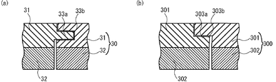
- FIG. 3 is sectional drawing which showed an example of the decorative material of this invention which concerns on another aspect, (a) shows the case where this actual process was given, (b) is a decision. The case where processing was given is shown.
- the decorative material 30 (300) of the present invention has a side surface of the foamed resin layer 32 (302) below the male part 33a (303a) and a non-foamed resin layer.
- the side surface of the foamed resin layer 32 (302) below the female real part 33b (303b) and the side surface of the non-foamed resin layer 31 (301) are continuous. It is preferable to form a surface.
- 3A and 3B is bonded to a foamed resin layer and a non-foamed resin layer as will be described later, the non-foamed resin layer is actually processed. At the same time, it can be obtained by cutting the foamed resin layer so that the foamed resin layers do not come into contact with each other even if the male part of one decorative material is fitted into the female part of another decorative material.
- the said foaming resin layer is a layer which mainly provides heat insulation, load bearing, and impact resistance to the decorative material of this invention, and is formed by foaming a foaming resin composition.
- the expansion ratio in the foamed resin layer is preferably 5 to 20 times. If it is out of the range, it may not be possible to obtain an excellent heat insulating, load bearing, and impact resistant decorative material. From the viewpoint of obtaining better heat insulation and load resistance, the expansion ratio of the foamed resin layer is preferably 5 to 15 times, and more preferably 5 to 12 times.
- the compression elastic modulus of the said foamed resin layer is 15 Mpa or more. If the compressive modulus is less than 15 MPa, an excellent load bearing and impact resistant decorative material may not be obtained. From the viewpoint of obtaining superior load resistance and impact resistance, the compression elastic modulus of the foamed resin layer is more preferably more than 15 MPa and not more than 150 MPa, and still more preferably not less than 20 MPa and not more than 120 MPa.
- the compression elastic modulus is a value obtained by preparing a test piece using the method described in JIS A9511: 2009 “Foamed plastic heat insulating material” using a foamed resin layer and performing measurement.
- a rectangular parallelepiped test piece having a length of 100 mm, a width of 100 mm, and a thickness of 3 mm is cut out from the foamed resin layer, and the test piece is taken from a direction perpendicular to the thickness direction using a tensile / compression tester.
- the compression elastic modulus is measured at a compression speed of 10 mm / min. Five test pieces are prepared, the compression elastic modulus is measured for each test piece as described above, and the value obtained by arithmetically averaging them is defined as the compression elastic modulus.
- the thickness of the rectangular parallelepiped test piece is changed to 3 mm instead of the thickness described in JIS.
- the non-foamed resin layer and the foamed resin layer both have a linear expansion coefficient of 8 ⁇ 10 ⁇ 5 / ° C. or less, and the non-foamed resin layer and the foamed resin layer have a linear expansion coefficient.
- the difference in expansion coefficient is preferably within 3 ⁇ 10 ⁇ 5 / ° C.
- the difference in linear expansion coefficient between the non-foamed resin layer and the foamed resin layer exceeds 3 ⁇ 10 ⁇ 5 / ° C.
- the difference in the degree of expansion / contraction of each layer with respect to the temperature change increases. Large warpage may occur.
- the linear expansion coefficients of the non-foamed resin layer and the foamed resin layer are both preferably 7 ⁇ 10 ⁇ 5 / ° C. or less, and more preferably 6 ⁇ 10 ⁇ 5 / ° C. or less.
- the difference between the linear expansion coefficients of the non-foamed resin layer and the foamed resin layer is more preferably within 2 ⁇ 10 ⁇ 5 / ° C., and within 1 ⁇ 10 ⁇ 5 / ° C.
- the linear expansion coefficients of the non-foamed resin layer and the foamed resin layer were determined by cutting a 145 mm long and 300 mm wide rectangular parallelepiped test piece from each layer member, and using the constant temperature bath, the test piece temperature was 0 ° C. and 40 ° C. The horizontal dimension when each is stabilized is measured, and the dimensional change per unit temperature obtained from the dimensional change rate is defined as the linear expansion coefficient.
- the foaming method of the foamed resin composition is not particularly limited, and any known method can be adopted, but foaming by a bead method is preferable from the viewpoint of obtaining a homogeneous foamed resin layer.
- the bead method uses expanded resin particles (pre-expanded particles) as a raw material, fills the expanded resin particles in a cavity of a mold, and pre-expands particles while secondary-expanding the filled pre-expanded particles with steam. This is a technique of obtaining a foamed resin layer by integrating them by heat fusion.
- the resin used for the foamed resin particles is preferably a thermoplastic resin.
- the thermoplastic resin include polyethylene (PE), polypropylene (PP), polystyrene (PS), styrene-modified polyolefin resin, ethylene-vinyl acetate copolymer resin (EVA), ethylene- (meth) acrylic acid resin, etc.
- Polyolefin resin acrylonitrile-butadiene-styrene copolymer (ABS resin), acrylonitrile-styrene copolymer, polyvinyl chloride resin (PVC), polyvinyl acetate resin, polyvinyl alcohol resin, etc., polyethylene terephthalate resin (PET)
- Polyester resins such as resin), nylon, polyacetal resin, acrylic resin, polycarbonate resin, polyurethane resin and other thermoplastic resins, and copolymers, or mixed resins thereof are preferably mentioned.
- a polyolefin resin is preferable, and a polystyrene resin is particularly preferable.
- the styrene monomer that forms the polystyrene resin is not particularly limited, and any known styrene monomer can be used. Examples include styrene, ⁇ -methyl styrene, vinyl toluene, chlorostyrene, ethyl styrene, isopropyl styrene, dimethyl styrene, bromostyrene, and the like. These styrenic monomers may be one kind or a mixture of plural kinds. A preferred styrene monomer is styrene.
- the foamed resin particles are usually made into resin particles by absorbing a monomer such as a styrene monomer together with a plasticizer, if necessary, into a seed particle comprising a resin that forms the foamed resin particles, and polymerizing the resin particles.
- the resin particles are obtained by impregnating a foaming agent and then foaming.
- Foamed resin particles can be obtained by impregnating particles obtained by suspension polymerization of a monomer such as styrene monomer in an aqueous medium with a foaming agent, or by introducing polystyrene resin into an extruder and melt-kneading together with the foaming agent. Then, it can be obtained by extruding into pressurized circulating water through a die having a small hole and foaming particles obtained by cutting using a rotary cutter in contact with the die.
- foaming agent examples include inorganic foaming agents such as sodium bicarbonate, sodium carbonate, ammonium bicarbonate, ammonium carbonate, and ammonium nitrite; N, N′-dimethyl-N, N′-dinitrosotephthalamide, N, N Nitroso compounds such as'-dinitrosopentamethylenetetramine; azo compounds such as azodicarbonamide, azobisformamide, azobisisobutyronitrile, azocyclohexylnitrile, azodiaminobenzene; sulfonyl hydrazides such as benzenesulfonyl hydrazide and toluenesulfonyl hydrazide Compounds: Azide compounds such as calcium azide, 4,4′-diphenyldisulfonyl azide, p-toluenesulfonyl azide and the like are preferred.
- blowing agent in addition to aliphatic hydrocarbons such as propane, normal butane, isopentane, normal pentane, and neopentane, fluorinated hydrocarbons such as difluoroethane and tetrafluoroethane that have zero ozone destruction coefficient
- volatile foaming agents such as These foaming agents can be used alone or in combination.
- the amount of the foaming agent to be added may be appropriately determined according to the desired expansion ratio and compression modulus, but is preferably 0.5 to 15 parts by mass, more preferably 1 to 10 parts by mass with respect to 100 parts by mass of the resin. preferable.
- plasticizer examples include fatty acid ester compounds such as propylene glycol fatty acid ester, glycerin fatty acid ester, sorbitan fatty acid ester, and sucrose fatty acid ester; dibutyl phthalate (DBP), dioctyl phthalate (DOP), diisononyl phthalate (DINP), etc.
- fatty acid ester compounds such as propylene glycol fatty acid ester, glycerin fatty acid ester, sorbitan fatty acid ester, and sucrose fatty acid ester
- DBP dibutyl phthalate
- DOP dioctyl phthalate
- DIDP diisononyl phthalate
- Phthalic acid ester compounds such as diisobutyl adipate and dioctyl adipate; sebacic acid ester compounds such as dibutyl sebacate and di2-ethylhexyl sebacate;
- Preferred examples include natural fats and oils such as liquid paraffin, coconut oil, palm oil, and rapeseed oil.
- the plasticizer may be added when the monomer is polymerized, or may be added when the foaming agent is impregnated.
- the addition amount of the plasticizer may be appropriately determined according to the desired expansion ratio and compression modulus, but is preferably 0.2 parts by mass or more and less than 3 parts by mass with respect to 100 parts by mass of the resin, 0.4 mass More preferably, it is more than 1.6 parts by mass. If the amount of the plasticizer added is 0.2 parts by mass or more, the secondary transition temperature is low, so it is advantageous for pre-foaming and molding at low temperature, and if it is less than 3 parts by mass, the foam is difficult to shrink, Good appearance can be obtained.
- the foamed resin particles have a flame retardant, a flame retardant aid, a lubricant, a binding inhibitor, a fusion accelerator, an antistatic agent, a spreading agent, a bubble regulator, and a crosslinking agent within a range that does not impair physical properties.
- Additives such as fillers, colorants, heat insulation improvers (radiation inhibitors, etc.) may be included.
- the above-mentioned foamed resin particles are filled in a mold cavity, and the filled pre-foamed particles are used using a heat medium such as steam at 100 to 150 ° C., preferably 100 to 120 ° C.
- a foamed resin layer can be obtained by integrating the pre-expanded particles by thermal fusion while performing secondary foaming with a heating time of 10 to 40 seconds.
- the average particle diameter of the foamed resin particles generally used is preferably 0.2 to 4 mm, more preferably 0.5 to 2 mm.
- the average particle diameter of the foamed resin particles is defined by JIS Z8801-1 “Test sieve—Part 1: Metal mesh sieve”, and a plurality of types of sieves having different openings. It is obtained by stacking the small sieve into a large sieve, putting 100 g of the foamed resin particles into the uppermost sieve, and vibrating the sieve to classify the foamed particles. Specifically, a value obtained by multiplying the average particle diameter of the foamed resin particles remaining on each sieve sieve by the number ratio is calculated, and the sum of these values is defined as the average particle diameter of the foamed resin particles.
- the foamed resin layer is not limited to the above-mentioned bead method, and the resin composition for forming the foamed resin layer includes a resin for a foamed resin layer, a foaming agent, a plasticizer, an inorganic filler, and other additives as necessary.
- a product by forming a non-foamed resin layer by a film forming method such as an extrusion film forming method using a T-die or a calendar film forming method, and then foaming it at about 220 to 250 ° C. using a heating foaming furnace. it can.
- a film forming method such as an extrusion film forming method using a T-die or a calendar film forming method
- a commercially available heat-insulating board for example, a bead method polystyrene foam heat insulating plate, an extrusion method polystyrene foam heat insulating plate, or the like may be used as long as it is within a predetermined expansion ratio and compression elastic modulus. it can.
- the thickness of the foamed resin layer is somewhat from 3 to 15 mm, more preferably from 5 to 15 mm, and even more preferably from 7 to 12 mm depending on the expansion ratio.
- the thickness of the foamed resin layer is within the above range, excellent heat insulation, load resistance and impact resistance can be obtained.
- the thickness of the said foamed resin layer is thicker than the support layer mentioned later. By being thicker than the support layer, excellent heat insulation, load resistance, and impact resistance can be obtained, and stress warpage due to difference in elongation from other layers such as support layer is unlikely to occur. Become.
- the non-foamed resin layer is a layer that has been subjected to the above-described actual processing and mainly imparts shape stability, water resistance, moisture resistance, impact resistance, and scratch resistance to the decorative material of the present invention.
- a layer having a rate of 180 MPa or more is preferable. If the tensile modulus is less than 180 MPa, scratch resistance cannot be obtained. From the viewpoint of obtaining excellent water resistance, moisture resistance, and scratch resistance, the tensile elastic modulus is preferably 180 MPa or more and 3000 MPa or less, more preferably 1000 MPa or more and 3000 MPa or less, and further preferably 2000 MPa or more and 2500 MPa or less. preferable.
- the non-foamed resin layer preferably contains a thermoplastic resin.
- the thermoplastic resin include polyvinyl resins such as polyvinyl chloride resin, polyvinyl acetate resin, and polyvinyl alcohol resin, polyethylene, polypropylene, polystyrene, styrene-modified polyolefin resin, ethylene-vinyl acetate copolymer resin (EVA), Polyolefin resin such as ethylene- (meth) acrylic resin, polyester resin such as polyethylene terephthalate resin (PET resin), acrylic resin, polycarbonate resin, polyurethane resin, acrylonitrile-butadiene-styrene copolymer (ABS resin), acrylonitrile
- thermoplastic resins such as styrene copolymers, copolymers, and mixed resins thereof. Of these, polyolefin resins, acrylonitrile-butadiene-styrene copolymers, and polyvinyl alcohol
- the non-foamed resin layer preferably contains an inorganic compound.
- an inorganic compound By including an inorganic compound, the linear expansion coefficient of the non-foamed resin layer can be reduced, and as a result, warpage of the decorative material of the present invention can be suppressed.
- the inorganic compound include talc, calcium carbonate, silica, mica and the like.
- the content of the inorganic compound is preferably 10 to 70 parts by mass with respect to 100 parts by mass of the resin component in the non-foamed resin layer.
- the linear expansion coefficient of the non-foamed resin layer may not be sufficiently reduced, and if it exceeds 70 parts by mass, the tensile elastic modulus of the non-foamed resin layer may be insufficient. .
- a more preferable range of the content of the inorganic compound is 10 to 65 parts by mass.
- the non-foamed resin layer may be composed of one layer or a laminate composed of two or more layers, but is a laminate composed of two or more layers, It is preferable that one layer contains a glass component. That is, the non-foamed resin layer is a laminate composed of two or more layers, preferably at least one layer is a thermoplastic resin layer and the other layer is a glass component layer containing a glass component. . With such a configuration, excellent impact resistance is obtained, and shape stability is improved.
- the glass component layer containing a glass component the layer comprised by glass fiber etc. is mentioned preferably, for example.
- the non-foamed resin layer is preferably a laminate in which a thermoplastic resin layer and a glass component layer are alternately laminated, and in particular, the first thermoplastic resin layer, the glass component layer, and the second heat layer. It is preferable that it is a laminated body which has a plastic resin layer in order.
- the non-foamed resin layer has a plurality of thermoplastic resin layers, the types of resins forming the plurality of thermoplastic resin layers may be the same or different, and the thickness of the plurality of thermoplastic resin layers May be the same or different.
- the thickness of the non-foamed resin layer is preferably 0.3 to 10 mm, and more preferably 1 to 5 mm.
- the thickness of the non-foamed resin layer is within the above range, excellent water resistance, moisture resistance, impact resistance, and scratch resistance can be obtained. Moreover, it becomes difficult to produce the stress curvature resulting from the difference in elongation by temperature etc. with other layers, such as a foamed resin layer.
- the thickness of the non-foamed resin layer is preferably thinner than the foamed resin layer. Stress warpage due to a difference in elongation due to temperature or the like with other layers such as a foamed resin layer layer is less likely to occur.
- the decorative layer is a layer that imparts decorativeness to the decorative material of the present invention, and may be, for example, a uniformly colored concealing layer (solid print layer), or various patterns using ink and a printing machine. Then, the pattern layer formed by printing may be used, or a layer (hereinafter referred to as a pattern layer) in which the masking layer and the pattern layer are combined.
- the decorative layer may be a pattern provided by a transfer method or the like, a veneer or a ground board obtained by thinly slicing wood, or a decorative sheet provided with a pattern on a colored base resin layer or base resin layer. But you can. Among them, the decorative sheet shown below is more preferable.
- the “decorative sheet” is an adhesive that bonds the base resin layer and the pattern layer, an arbitrary layer such as a transparent resin layer and a surface protective layer, which will be described later, and the pattern layer and the transparent resin layer, as shown below.
- the thing of the laminated structure which consists of an agent layer is preferable.
- the base on which the decorative material of the present invention is provided can be concealed, and when the foamed resin layer, the non-foamed resin layer, etc. are colored or uneven in color, the intended color can be obtained.
- the surface color can be provided.
- a grain pattern imitating the surface of a rock such as a wood grain pattern, marble pattern (for example, travertine marble pattern), a fabric pattern imitating a texture or cloth pattern, a tiled pattern, a brick
- a pattern such as a stacked pattern or a combination of these, such as a parquet or patchwork, can be applied to the decorative sheet.
- These patterns are formed by multicolor printing with the usual yellow, red, blue and black process colors, as well as by multicolor printing with special colors prepared by preparing the individual color plates constituting the pattern. Is done.
- a binder resin in which a colorant such as a pigment or a dye, an extender pigment, a solvent, a stabilizer, a plasticizer, a catalyst, or a curing agent is appropriately mixed is used.
- the binder resin is not particularly limited, and preferred examples include urethane resins, vinyl chloride / vinyl acetate copolymer resins, vinyl chloride / vinyl acetate / acrylic copolymer resins, acrylic resins, polyester resins, and nitrocellulose resins. It is done. Any of these binder resins can be used alone or in admixture of two or more.
- colorant examples include carbon black (black), iron black, titanium white, antimony white, yellow lead, titanium yellow, petal, cadmium red, ultramarine, cobalt blue, and other inorganic pigments, quinacridone red, and isoindolinone.
- Organic pigments such as yellow and phthalocyanine blue, metallic pigments composed of scaly foils such as dyes, aluminum and brass, pearlescent pigments composed of scaly foils such as titanium dioxide-coated mica and basic lead carbonate, etc. Is preferred.
- the thickness of the decorative layer is usually preferably about 5 ⁇ m to 3 mm.
- the thickness is preferably about 20 ⁇ m or less.
- the thickness is preferably about 0.5 mm or more and 3 mm or less, and when the decoration layer is a decorative sheet, the thickness is preferably about 500 ⁇ m or less. If the thickness of the said decoration layer exists in the said range, the design which was excellent in the decorative material of this invention can be provided, and concealment property can be provided.
- the base resin layer is a layer provided as desired, and is preferably a layer formed of a thermoplastic resin.
- a thermoplastic resin what was illustrated as a thermoplastic resin provided in the said foamed resin layer can be mentioned preferably.
- polyolefin resins are preferable, and polyethylene resins and polypropylene resins are more preferable.
- the base resin layer may be transparent or colored, and is preferably colored from the viewpoint of concealing the base on which the decorative material is provided.
- Preferred examples of the colorant used include those exemplified as the colorant used in the decorative layer.
- the thickness of the base resin layer is preferably 10 to 150 ⁇ m, more preferably 30 to 100 ⁇ m, and further preferably 40 to 80 ⁇ m. When the thickness of the base resin layer is within the above range, handling is easy and the decorative material of the present invention does not become thicker than necessary.
- a filler such as a flame retardant, a lubricant, antioxidant, a ultraviolet absorber, a light stabilizer, to a base resin layer as needed.
- the said transparent resin layer is an arbitrary layer provided in order to protect a decoration layer, Preferably it is a layer formed with a thermoplastic resin.
- a thermoplastic resin what was illustrated as a thermoplastic resin provided in said foamed resin layer can be mentioned preferably.
- polyolefin resins are preferable, and polyethylene resins, polypropylene resins, and ionomer resins are more preferable.
- the transparent resin layer is a transparent resin layer so that the decorative layer can be seen through.
- transparent is a concept including colorless and transparent as well as colored and translucent.
- various additives such as fillers, flame retardants, lubricants, antioxidants, ultraviolet absorbers, light stabilizers and the like may be added to the transparent resin layer as necessary without impairing its transparency. Also good.
- the thickness of the transparent resin layer is preferably 10 to 400 ⁇ m, more preferably 30 to 250 ⁇ m, and further preferably 50 to 100 ⁇ m.
- the thickness of the transparent resin layer is within the above range, the decorative layer can be protected, the handling is easy, and the cosmetic material does not become thicker than necessary.
- the surface protective layer is a layer provided as desired that imparts surface properties such as impact resistance, load resistance, and scratch resistance to the decorative material of the present invention.
- the surface protective layer is provided on the outermost surface of the decorative material of the present invention.
- the surface protective layer is preferably constituted by applying a resin composition containing a curable resin on the decorative layer, or a transparent resin layer and an adhesive layer that are preferably provided, and curing the resin composition. . By containing the curable resin that has been crosslinked and cured, the surface properties of the decorative material of the present invention can be improved.
- Preferred examples of the curable resin used to form the surface protective layer include ionizing radiation curable resins and thermosetting resins. A plurality of these are used, for example, ionizing radiation curable resins and thermosetting resins. A so-called hybrid type may be used together. Among these, ionizing radiation curable resins are preferable from the viewpoint of increasing the crosslinking density of the resin forming the surface protective layer and improving the surface characteristics, and some of them can be applied without a solvent and are handled. From the viewpoint of ease, an electron beam curable resin is more preferable.
- the ionizing radiation curable resin refers to a resin having an energy quantum capable of crosslinking and polymerizing molecules in electromagnetic waves or charged particle beams, that is, a resin that is crosslinked and cured by irradiation with ultraviolet rays or electron beams. .
- it can be appropriately selected from polymerizable monomers, polymerizable oligomers, or prepolymers conventionally used as ionizing radiation curable resins.
- the polymerizable monomer a (meth) acrylate monomer having a radical polymerizable unsaturated group in the molecule is preferable, and among them, a polyfunctional (meth) acrylate is preferable.
- the polyfunctional (meth) acrylate is not particularly limited as long as it is a (meth) acrylate having two or more ethylenically unsaturated bonds in the molecule. These polyfunctional (meth) acrylates may be used singly or in combination of two or more.
- an oligomer having a radical polymerizable unsaturated group in the molecule for example, epoxy (meth) acrylate, urethane (meth) acrylate, polyester (meth) acrylate, polyether (meth) An acrylate type etc. are mentioned.
- polymerizable oligomer other polybutadiene (meth) acrylate oligomer having a high hydrophobicity having a (meth) acrylate group in the side chain of the polybutadiene oligomer, and silicone (meth) acrylate having a polysiloxane bond in the main chain Oligomers, aminoplast resin (meth) acrylate oligomers modified from aminoplast resins with many reactive groups in small molecules, or molecules such as novolak epoxy resins, bisphenol epoxy resins, aliphatic vinyl ethers, aromatic vinyl ethers There are oligomers having cationically polymerizable functional groups.
- a monofunctional (meth) acrylate can be used in combination with the above polyfunctional (meth) acrylate as long as the purpose of the present invention is not impaired, for the purpose of reducing the viscosity.
- These monofunctional (meth) acrylates may be used alone or in combination of two or more.
- thermosetting resin examples include epoxy resin, phenol resin, urea resin, unsaturated polyester resin, melamine resin, alkyd resin, polyimide resin, silicone resin, hydroxyl functional acrylic resin, carboxyl functional acrylic resin, amide functional Preferred examples include a functional copolymer and a urethane resin.
- thermosetting resin also include a two-component curable resin, and specifically, a two-component curable resin of a polyol and an isocyanate is preferable.
- a polyol an acrylic polyol, a polyester polyol, an epoxy polyol etc. are mentioned preferably, for example.
- the isocyanate may be, for example, a polyvalent isocyanate having two or more isocyanate groups in the molecule, such as 2,4-tolylene diisocyanate (TDI), xylene diisocyanate (XDI), naphthalene diisocyanate, Aromatic isocyanates such as 4,4'-diphenylmethane diisocyanate, aliphatics such as 1,6-hexamethylene diisocyanate (HMDI), isophorone diisocyanate (IPDI), methylene diisocyanate (MDI), hydrogenated tolylene diisocyanate, hydrogenated diphenylmethane diisocyanate Polyisocyanates such as (or alicyclic) isocyanates are used. Alternatively, adducts or multimers of these various isocyanates, for example, adducts of tolylene diisocyanate, tolylene diisocyanate trimers, and the like are also used.
- various additives can be contained in the resin composition which comprises the said surface protective layer in the range which does not inhibit the performance.
- the various additives include ultraviolet absorbers (UVA), light stabilizers (HALS, etc.), polymerization inhibitors, crosslinking agents, antistatic agents, adhesion improvers, antioxidants, leveling agents, and thixotropic properties.
- the thickness of the surface protective layer is preferably 3 to 40 ⁇ m, more preferably 5 to 20 ⁇ m. When the thickness of the surface protective layer is within the above range, excellent surface characteristics can be obtained.
- the adhesive layer is a layer provided as necessary when laminating the resin layer when the base resin layer and the transparent resin layer are provided.
- the adhesive used in the adhesive layer include a urethane adhesive, an acrylic adhesive, an acrylic / urethane adhesive, a polyester adhesive, a polyester urethane adhesive, a polyamide adhesive, a polystyrene adhesive, and a cellulose adhesive. Preferably mentioned. These adhesives can be used singly or as a mixture of two or more.
- the thickness of the adhesive layer is preferably 1 to 30 ⁇ m, and more preferably 3 to 15 ⁇ m. When the thickness of the adhesive layer is within the above range, good adhesiveness is obtained, and the decorative material of the present invention is not unnecessarily thick.
- the decorative material of the present invention having each of the above layers has excellent impact resistance, heat insulation, water resistance, moisture resistance, load resistance, scratch resistance, and ease of construction. Yes, it is suitable for watering applications such as residential flooring, residential wall and ceiling panel materials, especially toilets, washbasins and kitchens.
- the thickness of the floor decorative material of the present invention is preferably 5 mm or more from the viewpoint of obtaining excellent impact resistance, heat insulation, water resistance, moisture resistance, load resistance, and scratch resistance, and is 6 to 30 mm. More preferred is 10 to 20 mm.
- the thickness of the wood flooring material is usually 8 mm, 12 mm, 15 mm, etc., and 12 mm is a standard thickness.
- the decorative material of the present invention can be produced, for example, through the following steps.
- the foamed resin layer is prepared.
- the foamed resin layer is preferably formed by a beading method or a film forming method such as an extrusion film forming method using a T die using a resin composition for forming a foamed resin layer or a calendar film forming method.
- the foaming is performed at a ratio of 20 times or less to produce a compression elastic modulus of 15 MPa or more.
- the expansion ratio and compression modulus of the foamed resin layer can be appropriately adjusted depending on the foaming temperature at the time of foaming, the type of resin, the amount of foaming agent and plasticizer used.
- the non-foamed resin layer is prepared.
- the non-foamed resin layer is formed by a film forming method such as an extrusion film forming method using a T-die or a calender film forming method so that the tensile elastic modulus is 180 MPa or more.
- the tensile elastic modulus of the non-foamed resin layer can be appropriately adjusted depending on the type of resin, the type and amount of inorganic compound used, and the like.
- a decorative layer is formed using the ink composition on the non-foamed resin layer or a base resin layer provided as necessary.
- the ink composition may be applied by a method such as gravure printing, offset printing, screen printing, flexographic printing, or ink jet printing.
- a concealing layer solid printing layer
- it may be formed by various coating methods such as gravure coating, bar coating, roll coating, reverse roll coating, and comma coating.
- the transparent resin layer is preferably formed via an adhesive layer as necessary after the decoration layer is formed.
- the adhesive layer may be formed by, for example, various coating methods such as gravure coating, bar coating, roll coating, reverse roll coating, and comma coating, extrusion film formation using a T-die, and the like.
- the above-mentioned transparent resin is a method of laminating at the same time as film formation by an extrusion film forming method using a T die, a dry lamination method using a film formed in advance by a film forming method such as an extrusion film forming method using a T die or a calendar film forming method. What is necessary is just to form by the method of laminating
- the surface protective layer is a curable resin after the decoration layer forming step or when the transparent resin layer is laminated, after the resin layer lamination step, on the decoration layer or on the transparent resin layer.
- the composition is applied, and an uncured resin layer is applied by a known method such as gravure coating, bar coating, roll coating, reverse roll coating, comma coating so that the thickness after curing is about 3 to 40 ⁇ m.
- the uncured resin layer can be formed by applying heat to the uncured resin layer or irradiating it with ionizing radiation such as an electron beam or ultraviolet rays to cure the uncured resin layer.
- the heating temperature in the case of thermosetting is appropriately determined according to the resin used.
- the acceleration voltage can be appropriately selected according to the resin used and the thickness of the layer, but it is preferable to cure the uncured resin layer usually at an acceleration voltage of about 70 to 300 kV.
- the irradiation dose is preferably such that the crosslinking density of the resin layer is saturated, and is usually selected in the range of 5 to 300 kGy (0.5 to 30 Mrad), preferably 10 to 50 kGy (1 to 5 Mrad).
- the electron beam source is not particularly limited.
- various electron beam accelerators such as a cockroft Walton type, a bandegraft type, a resonant transformer type, an insulated core transformer type, a linear type, a dynamitron type, and a high frequency type are used. be able to.
- ultraviolet rays are used as the ionizing radiation, those containing ultraviolet rays having a wavelength of 190 to 380 nm are emitted.
- an ultraviolet-ray source For example, a high pressure mercury lamp, a low pressure mercury lamp, a metal halide lamp, a carbon arc lamp etc. are used.
- the non-foamed resin layer and the decorative layer can be attached using, for example, a hot-melt adhesive, in addition to a heat-sensitive adhesive and a pressure-sensitive adhesive.
- a hot-melt adhesive for example, a reactive hot-melt adhesive such as a urethane-based reactive hot melt (hereinafter referred to as “PUR-based adhesive”) is preferably exemplified.
- PUR-based adhesive contains a functional group (isocyanate group) that reacts with moisture in the components, and reacts with moisture attached to the substrate and the decorative sheet and moisture given through them after cooling and curing. After the reaction, it does not melt even when heated and has a high adhesive strength.
- Adhesion between the foamed resin layer obtained in the preparation step of the foamed resin layer and the non-foamed resin layer forming the decorative layer is the adhesive shown in the adhesive step between the non-foamed resin layer and the decorative layer. Can be used.
- a male part is formed on at least one side of the polygon of the non-foamed resin layer formed with the foamed resin layer.
- a female real part capable of fitting the male real part into at least one other side of the polygon is formed. It does not specifically limit as a method of providing the said male real part and a female real part, A conventionally well-known method is mentioned.
- the step of forming the male real part and the female real part when the male real part of the one cosmetic material and the female real part of the other cosmetic material are fitted, the foam of the one cosmetic material is foamed.
- the foamed resin layer below the male real part and the female real part is cut so that the resin layer does not come into contact with the foamed resin layer of the other decorative material.
- a manufacturing method of the decorative material of the present invention that is, the step of forming the foamed resin layer on one side of the non-foamed resin layer, the step of forming the male real part and the female real part, the male real part and the female real part.
- the method for producing a decorative material according to the present invention which includes a step of cutting the foamed resin layer below each, is also one aspect of the present invention.
- a male real part is formed on the non-foamed resin layer on at least one side of the polygon described above, and a female real part capable of fitting the male real part into the above on at least one other side of the polygon.
- the decorative material of the present invention has a decorative layer, a non-foamed resin layer, and a foamed resin layer, and the ratio of the thickness of the non-foamed resin layer and the compression elastic modulus of the foamed resin layer are respectively defined to predetermined values. Therefore, it is excellent in water resistance and heat insulation and also in load resistance.
- Step 0.1 mm or less ⁇ : 0.1 mm or more to 0.3 mm or less ⁇ : 0.3 mm or more to 0.5 mm or less ⁇ : 0.5 mm or more “push-up” ⁇ : Visually indistinguishable ⁇ : Visually discriminable but slight and inconspicuous ⁇ : Easy to visually discern ⁇ : No flooring even when stepped on by person ⁇ : The flooring is heard when stepped on by person.
- the above “push-up” is a combination of makeup materials 50b and 50d. When the decorative materials 50b and 50d are fitted together, the “flooring” means that the fitting portions of the two decorative materials float upward. It means a state where the end is raised.
- the linear expansion coefficient at each measurement point is obtained, and the average value of the linear expansion coefficients at the three widths is obtained by calculating the linear expansion coefficient in the width direction, the length
- the average value of the linear expansion coefficients at the three locations is defined as the linear expansion coefficient in the length direction, and the linear expansion coefficient having a large value at any of the three positions is defined as the linear expansion coefficient of each layer.
- Example 1 On a colored polypropylene resin film (thickness: 60 ⁇ m, color: white), a 2 ⁇ m-thick pattern pattern was formed by gravure printing using an ink composition (acryl urethane). Next, an adhesive layer having a thickness of 2 ⁇ m was formed using an adhesive for urethane dry lamination, and a transparent polypropylene resin film (thickness: 80 ⁇ m) was dry laminated on the pattern layer. A primer layer having a thickness of 1 ⁇ m was formed on the transparent polypropylene resin film using a two-component curable urethane resin.
- an electron beam curable resin composition (acrylate system) is applied onto the primer layer by gravure printing at a coating amount of 15 g / m 2, a coating film is formed, and the coating film is crosslinked and cured by irradiation with an electron beam.
- a surface protective layer (thickness: 15 ⁇ m) was formed, and a decorative sheet (thickness: 160 ⁇ m) was produced, which was used as a decorative layer.
- a PP resin sheet (thickness: 3 mm) is prepared as a non-foamed resin layer, and the non-foamed resin layer and the decorative sheet are arranged so as to face the colored polypropylene resin film (base resin layer) of the decorative sheet.
- EPS resin foaming agent; butane (7 parts by mass with respect to 100 parts by mass of polystyrene resin), plasticizer; liquid paraffin (0.15 parts by mass with respect to 100 parts by mass of polystyrene resin) is used as the foamed resin layer.
- the foamed resin layer (foaming ratio: 10 times, thickness: 9 mm) prepared by the bead method is prepared, and the non-foamed resin layer and the foamed resin layer on which the decorative sheet is adhered are urethane-reactive hot melt Adhesive was used to make a decorative material as shown in FIG.
- the gap amount of the foamed resin layer when the produced decorative materials were fitted together was 2 mm.
- Example 2 After the non-foamed resin layer from Example 1 was changed from the PP resin sheet to the ABS resin sheet (thickness: 2 mm), the actual processing was changed from the actual to the settlement, and the foamed resin layer was adhered after the actual processing. A cosmetic material was produced in the same manner as in Example 1 except that the actual processing was changed. The gap amount of the foamed resin layer when the produced decorative materials were fitted together was 2 mm.
- Example 3 A cosmetic material was produced in the same manner as in Example 1 except that the actual processing was adjusted so that the gap between the foamed resin layers when the decorative materials were fitted together was 0.5 mm.
- Example 4 A cosmetic material was produced in the same manner as in Example 1 except that the actual processing was adjusted so that the gap between the foamed resin layers when the decorative materials were fitted together was 6 mm.
- Example 5 A cosmetic material was produced in the same manner as in Example 1 except that the actual processing was adjusted so that the gap between the foamed resin layers when the decorative materials were fitted together was 10 mm.
- Comparative Example 1 A cosmetic material was produced in the same manner as in Example 1 except that the actual processing was not performed (the cosmetic material having no fruit).
- Example 2 A cosmetic material was produced in the same manner as in Example 1 except that the actual processing was adjusted so that the gap between the foamed resin layers when the decorative materials were fitted together was 0 mm.
- production of floor noise was suppressed can be provided.
- the decorative material of the present invention is suitably used for a decorative material in which generation of floor noise as a floor and generation of squeaking as a panel material for walls and ceilings are suppressed.
Landscapes
- Engineering & Computer Science (AREA)
- Architecture (AREA)
- Civil Engineering (AREA)
- Structural Engineering (AREA)
- Floor Finish (AREA)
- Laminated Bodies (AREA)
Abstract
Description
これらの内装用化粧材は、断熱性能が低い為に、冬場等の気温が低い場合に、手や足で接触した際に冷たく感じるという問題がある。
また、夏場や冬場において、室内でエアコン等の冷房や暖房を使用する際に、室内表面を目的温度まで冷却したり、加温したりするのに多大なエネルギーを必要とし、電気代が高くなるという問題がある。
また、本発明の化粧材は、上記雄実部の下方の発泡樹脂層の側面が、上記雄実部を有する非発泡樹脂層の側面よりも、平面視多角形状の中心側に来るよう配置されている、若しくは、上記雌実部の下方の発泡樹脂層の側面が、上記雌実部を有する非発泡樹脂層の側面よりも、平面視多角形状の中心側に来るよう配置されている、又は、上記雄実部の下方の発泡樹脂層の側面、及び、上記雌実部の下方の発泡樹脂層の側面のいずれもが、上記非発泡樹脂層の側面よりも、平面視多角形状の中心側に来るよう配置されていることが好ましい。また、本発明の化粧材は、上記雄実部の下方の発泡樹脂層の側面が、上記雄実部を有する非発泡樹脂層の側面よりも、平面視多角形状の中心側に来るよう配置され、上記雌実部の下方の発泡樹脂層の側面が、上記雌実部を有する非発泡樹脂層の側面よりも、平面視多角形状の中心側と反対側に来るよう配置され、上記雄実部の下方の発泡樹脂層の側面と非発泡樹脂層の側面との距離が、上記雌実部の下方の発泡樹脂層の側面と非発泡樹脂層の側面との距離よりも大きいことが好ましい。
また、本発明の化粧材は、上記雄実部の下方の発泡樹脂層の側面と上記非発泡樹脂層の側面とが連続的に面を構成し、上記雌実部の下方の発泡樹脂層の側面と非発泡樹脂層の側面とが連続的に面を構成していることが好ましい。
また、このような化粧材は、非発泡樹脂層に所定の実加工を施した後、発泡樹脂層の貼り付け位置を高度に制御しながら非発泡樹脂層に貼り付ける方法により製造することができ、また、上記非発泡樹脂層と上記発泡樹脂層とを貼り付けた後、非発泡樹脂層に所定の実加工を施すと同時に発泡樹脂層の切削を行うことでも製造することができる。
本発明の化粧材は、平面視多角形状であるが、上記多角形としては、具体的には三角形、四角形、五角形等必要に応じた形状であってよく特に限定されない。
上記実加工としては特に限定されず、例えば、本実加工、相決り(あいじゃくり)加工等公知の加工であってよい。
ここで、一般的に、実(さね)とは、例えば、図4(a)に示したように、床や壁パネル等の木質材等からなる基材の側面に嵌合可能な形状にて形成される突出部や溝状凹部のことをいう。更に、図1(a)に示したように、非発泡樹脂層11の側面に突出部13a(雄実部)と、その突出部に嵌合可能な形状の溝状凹部13b(雌実部)とを備えるものを、一般的に本実(ほんざね)といい、図2(a)に示したように、非発泡樹脂層21の側面に突出部23a(雄実部)と、その突出部に嵌合可能な形状の溝状凹部23b(雌実部)とを備えるものを、一般的に相決り(あいじゃくり)という。そして、このような本実を化粧材に設けることで、図4(b)に示したように、隣接する複数の基材の各々に設けられた雄実と雌実とを嵌合させ、施工することができる。
具体的には、本発明の化粧材は、上記多角形の少なくとも一の辺の上記非発泡樹脂層に雄実部が形成され、上記多角形の少なくとも他の一の辺の上記非発泡樹脂層に上記雄実部を嵌め入れ可能な雌実部が形成されている。
また、本発明の化粧材は、一の上記化粧材の雄実部と他の上記化粧材の雌実部とを嵌め入れたときに、上記一の化粧材の上記発泡樹脂層と、上記他の化粧材の発泡樹脂層とが接触しない。このような態様で本発明の化粧材が設置されることで、発泡樹脂層同士が接触することに起因した床鳴りや軋み音を効果的に抑制できる。
このような態様の本発明の化粧材としては、例えば、図1(a)に示した態様や図2(a)に示した態様等が挙げられる。
すなわち、図1(a)には、本実加工が施された本発明の化粧材の断面の一例を示し、(b)には、本実加工が施された本発明の化粧材の断面の別の一例を示し、図2(a)には、相決り加工が施された本発明の化粧材の断面の一例を示し、(b)は、相決り加工が施された本発明の化粧材の断面の別の一例を示す。
図1(a)に示した本発明の床用化粧板10(図2(a)に示した本発明の床用化粧板20)は、非発泡樹脂層11(21)と発泡樹脂層12(22)とを備え、非発泡樹脂層11(21)の一の辺に雄実部13a(23a)が設けられ、他の辺に雌実部13b(23b)が設けられており、発泡樹脂層12(22)は、その側面12a(22a)が非発泡樹脂層11(21)の実構造部分よりも平面視多角形状の中心側(以下、内側ともいう)となるように非発泡樹脂層11(21)に貼り付けられている。
図4(a)は、図1(a)に示した構造の化粧材の平面図であり、図4(b)は、(a)に示した本発明の化粧材を嵌め合せた状態を示す模式図であるが、図4(b)に示したように、一の化粧材の一の辺に設けられた雄実部13aが他の化粧材の一の辺に設けられた雌実部13bに嵌め入れられた嵌合部13cで本発明の化粧材同士は嵌合させられるが、発泡樹脂層12同士は接触せず床鳴りが生じることもない。
具体的には、図1(b)に示した本発明の床用化粧板100(図2(b)に示した本発明の床用化粧板200)のように、非発泡樹脂層101(201)と発泡樹脂層102(202)とを備え、非発泡樹脂層101(201)の一の辺に雄実部103a(203a)が設けられ、他の辺に雌実部103b(203b)が設けられており、雄実部103a(203a)の下方の発泡樹脂層102(202)の側面102a(202a)が非発泡樹脂層101(201)の側面より内側に来るよう配置され、雌実部103b(203b)の下方の発泡樹脂層102(202)の側面102b(202b)が非発泡樹脂層101(201)の側面より外側に来るよう配置されている。
そして、雄実部103a(203a)の下方の発泡樹脂層102(202)の側面102a(202a)と非発泡樹脂層101(201)の側面との距離が、雌実部103b(203b)の下方の発泡樹脂層102(202)の側面102b(202b)と非発泡樹脂層の側面との距離よりも大きい。
そして、図1(b)及び図2(b)に示したように、雄実部103a(203a)が他の化粧材の一の辺に設けられた雌実部103b(203b)に嵌め入れられると、発泡樹脂層102(202)同士は接触せず床鳴りが生じることもない。
図3(a)及び(b)に示した本発明の化粧材は、後述するように発泡樹脂層と非発泡樹脂層とを貼り合せた後、非発泡樹脂層に対して実加工を施すと同時に、一の化粧材の雄実部を他の化粧材の雌実部に嵌め入れても互いに発泡樹脂層同士が接触しないように、該発泡樹脂層の切削を行うことで得ることができる。
上記発泡樹脂層は、本発明の化粧材に主に断熱性、耐荷重性、及び耐衝撃性を付与する層であり、発泡樹脂組成物を発泡して形成される。
上記発泡樹脂層における発泡倍率は5~20倍であることが好ましい。当該範囲を外れると、優れた断熱性、耐荷重性、及び耐衝撃性の化粧材が得られないことがある。より優れた断熱性、及び耐荷重性を得る観点から、上記発泡樹脂層の発泡倍率は5~15倍がより好ましく、5~12倍が更に好ましい。
ここで、上記圧縮弾性率は、発泡樹脂層を用いて、JIS A9511:2009「発泡プラスチック保温材」に記載の方法を用いて試験片を作製し測定を行った値である。
具体的には、上記発泡樹脂層から縦100mm、横100mm、厚さ3mmの直方体形状の試験片を切り出し、引張・圧縮試験機を用いて、厚み方向に対して、垂直の方向から該試験片を圧縮速度10mm/分にて圧縮弾性率の測定を行う。試験片を5個用意し、試験片ごとに上記要領で圧縮弾性率を測定し、それらを相加平均した値を圧縮弾性率とする。なお直方体形状の試験片の厚みはJIS記載の厚みではなく、3mmに変更している。
上記非発泡樹脂層及び/又は上記発泡樹脂層の線膨張係数が8×10-5/℃を超えると、温度変化に対する化粧材の伸縮が大きい為、伸びる場合には化粧材の反りや勘合部の突き上げ等、縮む場合には勘合部の隙間が開く等の不具合が発生することがある。
また、上記非発泡樹脂層及び上記発泡樹脂層の線膨張係数の差が3×10⁻⁵/℃を超えると、温度変化に対し各層の伸縮度合いの差が大きくなるため、本発明の化粧材に大きな反りが発生してしまうことがある。
上記非発泡樹脂層及び上記発泡樹脂層の線膨張係数は、いずれも7×10⁻⁵/℃以下であることがより好ましく、6×10-5/℃以下であることが更に好ましい。また、上記非発泡樹脂層及び上記発泡樹脂層の線膨張係数の線膨張係数の差は、2×10-5/℃以内であることがより好ましく、1×10-5/℃以内であることが更に好ましい。
ここで、上記非発泡樹脂層及び上記発泡樹脂層の線膨張係数は、各層部材から縦145mm、横300mmの直方体状の試験片を切り出し、恒温槽を用いて0℃及び40℃に試験片温度を安定させた際の横方向の寸法をそれぞれ測定し、その寸法変化率から得られる単位温度当たりの寸法変化量を線膨張係数とする。
上記熱可塑性樹脂としては、ポリエチレン(PE)、ポリプロピレン(PP)、ポリスチレン(PS)、スチレン改質ポリオレフィン樹脂、エチレン-酢酸ビニル共重合体樹脂(EVA)、エチレン-(メタ)アクリル酸系樹脂などのポリオレフィン樹脂、アクリロニトリル-ブタジエン-スチレン共重合体(ABS樹脂)、アクリロニトリル-スチレン共重合体、ポリ塩化ビニル樹脂(PVC)、ポリ酢酸ビニル樹脂、ポリビニルアルコール樹脂などのポリビニル樹脂、ポリエチレンテレフタレート樹脂(PET樹脂)などのポリエステル樹脂、ナイロン、ポリアセタール樹脂、アクリル樹脂、ポリカーボネート樹脂、ポリウレタン樹脂などの熱可塑性樹脂の単体及び共重合体、あるいは、これらの混合樹脂が好ましく挙げられる。
これらのなかでも、樹脂自体の強度を考慮すると、ポリオレフィン樹脂が好ましく、特にポリスチレン樹脂が好ましい。
また、発泡剤としては、物理発泡剤としてプロパン、ノルマルブタン、イソペンタン、ノルマルペンタン、ネオペンタンなどの脂肪族炭化水素類のほか、ジフルオロエタン、テトラフルオロエタンなどのオゾン破壊係数がゼロであるフッ化炭化水素類などの揮発性発泡剤も好ましく挙げられる。
これらの発泡剤は、単独又は複数を組み合わせて用いることができる。
上記発泡剤の添加量は、所望する発泡倍率や圧縮弾性率に応じて適宜決めればよいが、樹脂100質量部に対して、0.5~15質量部が好ましく、1~10質量部がより好ましい。
上記可塑剤は、モノマーを重合する際に添加してもよいし、発泡剤を含浸させる際に添加してもよい。
上記可塑剤の添加量は、所望する発泡倍率や圧縮弾性率に応じて適宜決めればよいが、樹脂100質量部に対して、0.2質量部以上3質量部未満が好ましく、0.4質量部以上1.6質量部未満がより好ましい。上記可塑剤の添加量が0.2質量部以上であると二次転移温度が低くなるので低温での予備発泡及び成形に優位であり、3質量部未満であると発泡体が収縮し難く、良好な見栄えが得られる。
具体的には、各目開きの篩上に残留した発泡樹脂粒子の平均粒子径に、その個数比率を乗じた値を算出し、それらの値の総和を発泡樹脂粒子の平均粒子径とする。
平均粒子径 = Σ(各篩上の個数比率 × 各篩上粒子の平均粒子径)
ここで、個数比率とは各篩上に残留した発泡粒子の重量比率及び各篩の目開きの大きさから得られる値である。
また、本発明において発泡樹脂層は、上記のビーズ法に限らず、発泡樹脂層用樹脂、発泡剤、可塑剤、無機充填剤、その他必要に応じた添加剤を含む発泡樹脂層形成用樹脂組成物を、Tダイによる押出製膜法やカレンダー製膜法などの製膜法により未発泡樹脂層を製膜してから、加熱発泡炉を用いて220~250℃程度で発泡させて得ることもできる。
また、上記発泡樹脂層の厚さは、後述する支持体層より厚いことが好ましい。支持体層より厚いことで、優れた断熱性、耐荷重性、及び耐衝撃性が得られ、また支持体層などの他の層との湿気などによる伸びの違いに起因する応力反りが生じにくくなる。
上記非発泡樹脂層は、上述した実加工が施され、本発明の化粧材に主に形状安定性、耐水性、防湿性、耐衝撃性、及び、耐傷性を付与する層であり、引張弾性率が180MPa以上である層であることが好ましい。引張弾性率が180MPa未満であると、耐傷性が得られない。優れた耐水性、防湿性、及び耐傷性を得る観点から、引張弾性率は180MPa以上3000MPa以下であることが好ましく、1000MPa以上3000MPa以下であることがより好ましく、2000MPa以上2500MPa以下であることがさらに好ましい。
また、引張弾性率が上記範囲内であると、発泡樹脂層などの他の層との温度などによる伸びの違いに起因する応力反りが生じにくくなる。ここで、引張弾性率(E)は、JIS K6732(1996)に記載されたダンベル型試験片に打ち抜いた非発泡樹脂層を用意し、20℃の温度条件下にて、引張圧縮試験機を用い、引張速度50mm/分、チャック間距離80mmの条件で測定して得られた引張応力-ひずみ曲線の初めの直線部分から、次の式によって計算した。
E=△p/△E
E:引張弾性率
△p:直線上の2点間の元の平均断面積による応力差
△E:同じ2点間のひずみ差
上記熱可塑性樹脂としては、ポリ塩化ビニル樹脂、ポリ酢酸ビニル樹脂、ポリビニルアルコール樹脂などのポリビニル樹脂、ポリエチレン、ポリプロピレン、ポリスチレン、スチレン改質ポリオレフィン系樹脂、エチレン-酢酸ビニル共重合体樹脂(EVA)、エチレン-(メタ)アクリル酸系樹脂などのポリオレフィン樹脂、ポリエチレンテレフタレート樹脂(PET樹脂)などのポリエステル樹脂、アクリル樹脂、ポリカーボネート樹脂、ポリウレタン樹脂、アクリロニトリル-ブタジエンースチレン共重合体(ABS樹脂)、アクリロニトリル-スチレン共重合体などの熱可塑性樹脂の単体及び共重合体、あるいは、これらの混合樹脂が好ましく挙げられる。なかでも、ポリオレフィン樹脂やアクリロニトリル-ブタジエン-スチレン共重合体、ポリ塩化ビニル樹脂が好ましい。
上記無機化合物としては、例えば、タルク、炭酸カルシウム、シリカ、マイカ等が挙げられる。
上記無機化合物の含有量としては、非発泡樹脂層中の樹脂成分100質量部に対し、10~70質量部であることが好ましい。10質量部未満であると非発泡樹脂層の線膨張係数を充分に低減させることができないことがあり、70質量部を超えると、非発泡樹脂層の引張弾性率が不充分となることがある。上記無機化合物の含有量のより好ましい範囲は10~65質量部である。
ガラス成分を含むガラス成分層は、例えばガラス繊維により構成される層などが好ましく挙げられる。
非発泡樹脂層が複数の熱可塑性樹脂層を有する場合、該複数の熱可塑性樹脂層を形成する樹脂の種類は同じであっても異なっていてもよく、また複数の熱可塑性樹脂層の厚さは同じであっても異なっていてもよい。
また、非発泡樹脂層の厚さは、上記したように、発泡樹脂層よりも薄いことが好ましい。発泡樹脂層層などの他の層との温度などによる伸びの違いに起因する応力反りが生じにくくなる。
上記装飾層は、本発明の化粧材に装飾性を付与する層であり、例えば、均一に着色が施された隠蔽層(ベタ印刷層)でもよいし、種々の模様をインキと印刷機を使用して印刷することにより形成される絵柄層であってもよいし、隠蔽層と絵柄層とを組み合わせた層(以下、模様層)であってもよい。上記装飾層としては、その他、転写法等で設けられた模様でもよいし、木材を薄くスライスした突板や挽き板でもよいし、着色されたベース樹脂層やベース樹脂層に模様を設けた化粧シートでもよい。そして、その中でも以下に示す化粧シートがより好ましい。なお、上記「化粧シート」とは、以下に示すように、ベース樹脂層及び模様層と、後述する透明樹脂層や表面保護層等の任意の層と、模様層及び透明樹脂層を接着する接着剤層とからなる積層構造のものが好ましい。
また、上記絵柄層を設けることで、木目模様、大理石模様(例えばトラバーチン大理石模様) などの岩石の表面を模した石目模様、布目や布状の模様を模した布地模様、タイル貼模様、煉瓦積模様など、あるいはこれらを複合した寄木、パッチワークなどの模様を化粧シートに付与することができる。これらの模様は通常の黄色、赤色、青色、及び黒色のプロセスカラーによる多色印刷によって形成される他、模様を構成する個々の色の版を用意して行う特色による多色印刷などによっても形成される。
上記バインダー樹脂としてはこれらの中から任意のものを、1種単独で又は2種以上を混合して用いることができる。
また、上記着色剤としては、カーボンブラック(墨)、鉄黒、チタン白、アンチモン白、黄鉛、チタン黄、弁柄、カドミウム赤、群青、コバルトブルーなどの無機顔料、キナクリドンレッド、イソインドリノンイエロー、フタロシアニンブルーなどの有機顔料、又は染料、アルミニウム、真鍮などの鱗片状箔片からなる金属顔料、二酸化チタン被覆雲母、塩基性炭酸鉛などの鱗片状箔片からなる真珠光沢(パール)顔料などが好ましく挙げられる。
上記装飾層が隠蔽層(ベタ印刷層)や絵柄層、隠蔽層と絵柄層とを組み合わせた模様層、転写法等で設けられた模様である場合、厚みは20μm以下程度であることが好ましく、上記装飾層が突板や挽き板である場合、厚みは0.5mm以上3mm以下程度であることが好ましく、上記装飾層が化粧シートである場合、厚みは500μm以下程度であることが好ましい。
上記装飾層の厚さが上記範囲内にあれば、本発明の化粧材に優れた意匠を付与することができ、また隠蔽性を付与することができる。
ベース樹脂層は所望に応じて設けられる層であり、好ましくは熱可塑性樹脂により形成される層である。上記熱可塑性樹脂としては、上記発泡樹脂層に設けられる熱可塑性樹脂として例示したものを好ましく挙げることができる。なかでも、ポリオレフィン樹脂が好ましく、ポリエチレン樹脂、ポリプロピレン樹脂がより好ましい。
上記透明樹脂層は装飾層を保護するために設けられる任意の層であり、好ましくは熱可塑性樹脂により形成される層である。熱可塑性樹脂としては、上記の発泡樹脂層に設けられる熱可塑性樹脂として例示したものを好ましく挙げることができる。なかでも、ポリオレフィン樹脂が好ましく、ポリエチレン樹脂、ポリプロピレン樹脂、アイオノマー樹脂がより好ましい。
また、上記透明樹脂層には、その透明性を損なわない範囲で必要に応じ、充填剤、難燃剤、滑剤、酸化防止剤、紫外線吸収剤、光安定剤等の各種の添加剤を添加してもよい。
上記表面保護層は、本発明の化粧材に耐衝撃性、耐荷重性、及び耐傷性などの表面特性を付与する、所望に応じて設けられる層である。表面保護層は、本発明の化粧材の最表面に設けられる。
上記表面保護層は、上記装飾層、あるいは好ましく設けられる透明樹脂層、接着剤層の上に、硬化性樹脂を含有する樹脂組成物を塗布し、これを硬化したもので構成されることが好ましい。架橋硬化された硬化性樹脂を含有することで、本発明の化粧材の表面特性を向上させることができる。
これらのうち、上記表面保護層を形成する樹脂の架橋密度を高め、表面特性を向上させる観点から、電離放射線硬化性樹脂が好ましく、また、無溶媒で塗布することができるものもあり、取り扱いが容易との観点から、電子線硬化性樹脂がさらに好ましい。
上記重合性モノマーとしては、分子中にラジカル重合性不飽和基を持つ(メタ)アクリレート系モノマーが好適であり、中でも多官能性(メタ)アクリレートが好ましい。多官能性(メタ)アクリレートとしては、分子内にエチレン性不飽和結合を2個以上有する(メタ)アクリレートであればよく、特に制限はない。これらの多官能性(メタ)アクリレートは1種を単独で用いてもよいし、2種以上を組み合わせて用いてもよい。
さらに、上記重合性オリゴマーとしては、他にポリブタジエンオリゴマーの側鎖に(メタ)アクリレート基をもつ疎水性の高いポリブタジエン(メタ)アクリレート系オリゴマー、主鎖にポリシロキサン結合をもつシリコーン(メタ)アクリレート系オリゴマー、小さな分子内に多くの反応性基をもつアミノプラスト樹脂を変性したアミノプラスト樹脂(メタ)アクリレート系オリゴマー、あるいはノボラック型エポキシ樹脂、ビスフェノール型エポキシ樹脂、脂肪族ビニルエーテル、芳香族ビニルエーテルなどの分子中にカチオン重合性官能基を有するオリゴマーなどがある。
ここで、上記ポリオールとしては、例えば、アクリルポリオール、ポリエステルポリオール、エポキシポリオールなどが好ましく挙げられる。
また、上記イソシアネートとしては、例えば、分子中に2個以上のイソシアネート基を有する多価イソシアネートであればよく、例えば、2,4-トリレンジイソシアネート(TDI)、キシレンジイソシアネート(XDI)、ナフタレンジイソシアネート、4,4’-ジフェニルメタンジイソシアネートなどの芳香族イソシアネート、1,6-ヘキサメチレンジイソシアネート(HMDI)、イソホロンジイソシアネート(IPDI)、メチレンジイソシアネート(MDI)、水素添加トリレンジイソシアネート、水素添加ジフェニルメタンジイソシアネートなどの脂肪族(乃至は脂環式)イソシアネートなどのポリイソシアネートが用いられる。あるいは、これら各種イソシアネートの付加体又は多量体、例えば、トリレンジイソシアネートの付加体、トリレンジイソシアネート3量体(trimer)なども用いられる。
上記各種添加剤としては、例えば、紫外線吸収剤(UVA)、光安定剤(HALSなど)、重合禁止剤、架橋剤、帯電防止剤、接着性向上剤、酸化防止剤、レベリング剤、チクソ性付与剤、カップリング剤、可塑剤、消泡剤、充填剤、溶剤などが挙げられる。
上記接着剤層は、上記ベース樹脂層と上記透明樹脂層とを設ける場合に、該樹脂層をラミネートする際に必要に応じて設けられる層である。
上記接着剤層に用いられる接着剤としては、例えば、ウレタン接着剤、アクリル接着剤、アクリル/ウレタン接着剤、ポリエステル接着剤、ポリエステルウレタン接着剤、ポリアミド接着剤、ポリスチレン接着剤、セルロース接着剤などが好ましく挙げられる。これらの接着剤は、1種単独で、あるいは2種以上の混合物として使用することができる。
また、施工容易性を考慮すると、リビングや廊下などの水廻り以外の箇所に設けられる木質フローリング材と同じ厚さとすることが好ましい。
木質フローリング材の厚さは、通常8mm、12mm、15mmなどがあり、12mmが標準的な厚さである。
本発明の化粧材は、例えば、以下の工程を経て製造することができる。
まず、上記発泡樹脂層を準備する。
上記発泡樹脂層は、上述した通り、ビーズ法、あるいは発泡樹脂層形成用樹脂組成物を用いたTダイによる押出製膜法やカレンダー製膜法などの成膜法により、好ましくは発泡倍率5倍以上20倍以下で発泡させて、圧縮弾性率が15MPa以上となるように作製する。
上記発泡樹脂層の発泡倍率や圧縮弾性率は、発泡させる際の発泡温度、樹脂の種類、発泡剤及び可塑剤の使用量などにより適宜調整することが可能である。
次に、上記非発泡樹脂層を準備する。
上記非発泡樹脂層は、Tダイによる押出製膜法やカレンダー製膜法などの製膜法により製膜し、引張弾性率が180MPa以上となるように作製する。
上記非発泡樹脂層の引張弾性率は、樹脂の種類、無機化合物の種類や使用量などにより適宜調整することが可能である。
上記非発泡樹脂層、または必要に応じて設けられるベース樹脂層上に、インキ組成物を用いて、装飾層を形成する。インキ組成物は、例えば、グラビア印刷、オフセット印刷、スクリーン印刷、フレキソ印刷、インクジェット印刷などの方法により塗布すればよい。また、隠蔽層(ベタ印刷層)を形成する場合には、例えば、グラビアコート、バーコート、ロールコート、リバースロールコート、コンマコートなどの各種コーティング法などにより形成すればよい。
上記透明樹脂層は、上記装飾層を形成した後、必要に応じて接着剤層を介して形成することが好ましい。上記接着剤層は、例えば、グラビアコート、バーコート、ロールコート、リバースロールコート、コンマコートなどの各種コーティング法、Tダイによる押出製膜法などにより形成すればよい。そして上記透明性樹脂はTダイによる押出製膜法で製膜と同時に積層させる方法、Tダイによる押出製膜法やカレンダー製膜法などの製膜法により予め製膜したものをドライラミネーション法や熱ラミネーション法により積層させる方法などにより形成すればよい。
上記表面保護層は、上記の装飾層の形成工程の後、あるいは透明樹脂層を積層する場合は該樹脂層の積層工程の後、装飾層の上、あるいは透明樹脂層の上に、硬化性樹脂組成物を塗布し、硬化後の厚さが3~40μm程度になるように、グラビアコート、バーコート、ロールコート、リバースロールコート、コンマコート等の公知の方式により塗布して未硬化樹脂層を形成し、次いで該未硬化樹脂層に、熱を加えるか又は電子線、紫外線等の電離放射線を照射して該未硬化樹脂層を硬化させることにより形成することができる。
また、電離放射線として電子線を用いる場合、その加速電圧については、用いる樹脂や層の厚みに応じて適宜選定し得るが、通常加速電圧70~300kV程度で未硬化樹脂層を硬化させることが好ましい。照射線量は、樹脂層の架橋密度が飽和する量が好ましく、通常5~300kGy(0.5~30Mrad)、好ましくは10~50kGy(1~5Mrad)の範囲で選定される。
電子線源としては特に制限はなく、例えば、コックロフトワルトン型、バンデグラフト型、共振変圧器型、絶縁コア変圧器型、あるいは直線型、ダイナミトロン型、高周波型等の各種電子線加速器を用いることができる。
電離放射線として紫外線を用いる場合には、波長190~380nmの紫外線を含むものを放射する。
紫外線源としては特に制限はなく、例えば、高圧水銀燈、低圧水銀燈、メタルハライドランプ、カーボンアーク燈等が用いられる。
装飾層が化粧シートである場合、上記非発泡樹脂層と前記装飾層との貼着は、例えば、感熱接着剤、感圧接着剤のほか、ホットメルト接着剤などを用いて行うことができる。ホットメルト接着剤としては、例えばウレタン系反応型ホットメルト(以下、「PUR系接着剤」という。)などの反応型ホットメルト接着剤が好ましく挙げられる。このPUR系接着剤は、成分の中に水分と反応する官能基(イソシアネート基)を含んでおり、冷却硬化後、基板や化粧シートに付着している水分やそれらを通して与えられる水分と反応する。
反応後は、加熱をしても溶融せず、高い接着強度を有するという特徴を有するものである。
上記発泡樹脂層の準備工程で得られた発泡樹脂層と、装飾層を形成した非発泡樹脂層との貼着は、上記非発泡樹脂層と装飾層との貼着工程で示した接着剤を用いることができる。
上記雄実部及び雌実部を設ける方法としては特に限定されず、従来公知の方法が挙げられる。
当該雄実部と雌実部とを形成する工程において、一の上記化粧材の雄実部と他の上記化粧材の雌実部とを嵌め入れたときに、上記一の化粧材の上記発泡樹脂層と、上記他の化粧材の発泡樹脂層とが接触しないように、上記雄実部及び雌実部のそれぞれ下方の発泡樹脂層の切削加工を行う。
このような本発明の化粧材の製造方法、すなわち、非発泡樹脂層の一方の面の発泡樹脂層を形成する工程、雄実部及び雌実部を形成する工程、雄実部及び雌実部のそれぞれ下方の発泡樹脂層の切削加工を行う工程を有する本発明の化粧材の製造方法もまた、本発明の一つである。
各実施例及び比較例で得られた化粧材について、以下の方法で評価及び測定した。
図5(a)、(b)に示したように幅450mm、長さ900mmサイズの化粧材50a~50dを、ウレタン系接着剤55を300mmピッチで塗布したモルタル上に4枚施工(1週間養生)した後に、5℃×3日間から40℃×3日間の環境放置し、下記項目を評価した。なお、各実施例及び比較例で得られた化粧材は、短辺及び長辺に雄実部と雌実部とがそれぞれ1組ずつ設けられている。
「段差」
◎:0.1mm以下
○:0.1mm超え~0.3mm以下
△:0.3mm超え~0.5mm以下
×:0.5mm超え
「突き上げ」
○:目視上判別不可
△:目視判別可だが軽微で目立たない
×:目視で容易に判別
「床鳴り」
○:人が踏んでも床鳴りなし
×:人が踏んだ際に床鳴りが聞こえる
なお、図5(b)に示したように、上記「突き上げ」とは、化粧材50bと50dとを嵌め合わせた際に、両化粧材の嵌合部が上に浮き上がることをいい、「床鳴り」とは、化粧材50bと50dとを嵌め合わせた際に、一方又は両方の化粧材50b、50dの外側端部が盛り上がる状態を意味する。
図5(c)に示したように、化粧材50b、50dの嵌合部の中心(雄実と雌実を嵌め合わせた部分の表面保護層面から確認できる境界部)に接する形状が1辺2cm角の正方形である金属治具51を置き、圧力が5kg/cm2となるように重りを加え、1週間放置し、重りを取り除いた直後の外観状態を以下の基準で評価した。
○:目視で金属製治具の跡を判別不可能
△:目視で金属製治具の跡が判別可能だが、軽微で目立たない
×:目視で容易に金属製治具の跡が判別できる
化粧材の各層から縦145mm、横300mmの直方体状の試験片を切り出し、恒温槽(エスペック社製ビルドインチャンバー、TBL-6E20W0P2T)を用いて0℃及び40℃に試験片温度を安定させた試験片の幅、長さに対し、中央及び端部から50mm中央側に入った箇所の計3箇所の寸法を、0.01mmまで読み取れるデジタルノギスを用いて測定する。
各温度、各箇所にて得られた幅、長さ寸法から寸法変化量を算出し、0℃での寸法値で除した値を寸法変化率:△Lとする。
上記で得られた△Lを、温度変化量:△Tで除することで各測定箇所における線膨張係数が得られ、幅3箇所における線膨張係数の平均値を幅方向の線膨張係数、長さ3箇所における線膨張係数の平均値を長さ方向の線膨張係数とし、いずれかにおいて大きい値となる線膨張係数を各層の線膨張係数とする。
着色ポリプロピレン樹脂フィルム(厚さ;60μm、色;白系)に、グラビア印刷でインキ組成物(アクリルウレタン系)を用いて厚さ2μmの石目柄の模様層を形成した。
次いで、ウレタン系ドライラミネート用接着剤を用いて厚さ2μmの接着剤層を形成し、該模様層の上に透明ポリプロピレン樹脂フィルム(厚さ;80μm)をドライラミネートして設けた。
該透明ポリプロピレン樹脂フィルム上に、2液硬化型ウレタン樹脂を用いて厚さ1μmのプライマー層を形成した。そして、該プライマー層上に電子線硬化性樹脂組成物(アクリレート系)をグラビア印刷によって塗布量15g/m2で塗布して、塗膜を形成し、電子線を照射して該塗膜を架橋硬化させ、表面保護層(厚さ:15μm)を形成して、化粧シート(厚さ;160μm)を作製し、装飾層とした。
次に、非発泡樹脂層としてPP樹脂シート(厚さ;3mm)を用意して、上記化粧シートの着色ポリプロピレン樹脂フィルム(ベース樹脂層)と対向するように、該非発泡樹脂層と該化粧シートとを、ウレタン系ドライラミネート用接着剤を介してドライラミネートにて貼着した。次に、貼着したものをテノーナー機にて非発泡樹脂層に実加工し、本実を設けた。そして、発泡樹脂層としてEPS樹脂(発泡剤;ブタン(ポリスチレン樹脂100質量部に対して7質量部)、可塑剤;流動パラフィン(ポリスチレン樹脂100質量部に対して0.15質量部))を用いてビーズ法により作製した発泡樹脂層(発泡倍率;10倍、厚さ;9mm)を用意し、上記の化粧シートを貼着した非発泡樹脂層と発泡樹脂層とを、ウレタン系反応型ホットメルト接着剤を用いて貼着し、図1(a)のような化粧材を作製した。作製した化粧材同士を嵌め合わせた時の発泡樹脂層の隙間量は2mmであった。
実施例1から非発泡樹脂層をPP樹脂シートからABS樹脂シート(厚さ;2mm)に、実加工を本実から相決りに変更し、発泡樹脂層の貼着を、実加工をした後から実加工をする前に変更した以外は、実施例1と同様にして化粧材を作製した。作製した化粧材同士を嵌め合わせたときの発泡樹脂層の隙間量は2mmであった。
化粧材同士を嵌め合わせたときの発泡樹脂層の隙間量が0.5mmとなるように実加工の調整をした以外は実施例1と同様にして化粧材を作製した。
化粧材同士を嵌め合わせたときの発泡樹脂層の隙間量が6mmとなるように実加工の調整をした以外は実施例1と同様にして化粧材を作製した。
化粧材同士を嵌め合わせた時の発泡樹脂層の隙間量が10mmとなるように実加工の調整をした以外は実施例1と同様にして化粧材を作製した。
実加工を行わなかった(実が無い状態の化粧材)以外は実施例1と同様にして化粧材を作製した。
化粧材同士を嵌め合わせた時の発泡樹脂層の隙間量が0mmとなるように実加工の調整をした以外は実施例1と同様にして化粧材を作製した。

11、21、31、101、201、301 非発泡樹脂層
12a、22a、102a、102b、202a、202b 側面
12、22、32、102、202、302 発泡樹脂層
13a、23a、33a、103a、203a、303a 雄実部
13b、23b、33b、103b、203b、303b 雌実部
13c 嵌合部
50a~d 化粧材
51 金属治具
55 ウレタン系接着剤
Claims (7)
- 発泡樹脂層と非発泡樹脂層とを備え、平面視多角形状の化粧材であって、
前記多角形の少なくとも一の辺の前記非発泡樹脂層に雄実部と、前記多角形の少なくとも他の一の辺の前記非発泡樹脂層に前記雄実部を嵌め入れ可能な雌実部とを備え、
一の前記化粧材の雄実部と他の前記化粧材の雌実部とを前記一の化粧材の前記発泡樹脂層と、前記他の化粧材の前記発泡樹脂層とが接触しない状態で嵌め入れ可能である
ことを特徴とする化粧材。 - 前記一の化粧材の雄実部と前記他の化粧材の雌実部とを嵌め入れたときに、前記一の化粧材の前記発泡樹脂層と、前記他の化粧材の発泡樹脂層とが10mm以下の隙間を備えた状態で嵌め入れされている請求項1記載の化粧材。
- 雄実部の下方の発泡樹脂層の側面が、前記雄実部を有する非発泡樹脂層の側面よりも、平面視多角形状の中心側に来るよう配置されている、若しくは、前記雌実部の下方の発泡樹脂層の側面が、前記雌実部を有する非発泡樹脂層の側面よりも、平面視多角形状の中心側に来るよう配置されている、又は、前記雄実部の下方の発泡樹脂層の側面、及び、前記雌実部の下方の発泡樹脂層の側面のいずれもが、前記非発泡樹脂層の側面よりも、平面視多角形状の中心側に来るよう配置されている請求項1又は2記載の化粧材。
- 雄実部の下方の発泡樹脂層の側面が、前記雄実部を有する非発泡樹脂層の側面よりも、平面視多角形状の中心側に来るよう配置され、
雌実部の下方の発泡樹脂層の側面が、前記雌実部を有する非発泡樹脂層の側面よりも、平面視多角形状の中心側と反対側に来るよう配置され、
前記雄実部の下方の発泡樹脂層の側面と非発泡樹脂層の側面との距離が、前記雌実部の下方の発泡樹脂層の側面と非発泡樹脂層の側面との距離よりも大きい請求項1又は2記載の化粧材。 - 雄実部の下方の発泡樹脂層の側面と非発泡樹脂層の側面とが連続的に面を構成し、雌実部の下方の発泡樹脂層の側面と非発泡樹脂層の側面とが連続的に面を構成している請求項1又は2記載の化粧材。
- 発泡樹脂層と非発泡樹脂層とを備え、平面視多角形状の化粧材の製造方法であって、
前記多角形の少なくとも一の辺の前記非発泡樹脂層に雄実部を形成し、前記多角形の少なくとも他の一の辺の前記非発泡樹脂層に前記雄実部を嵌め入れ可能な雌実部を形成する工程、
前記雄実部と雌実部とを形成した非発泡樹脂層に発泡樹脂層を貼り付ける工程を有し、
前記非発泡樹脂層に発泡樹脂層を貼り付ける工程において、一の前記化粧材の雄実部と他の前記化粧材の雌実部とを嵌め入れたときに、前記一の化粧材の前記発泡樹脂層と、前記他の化粧材の発泡樹脂層とが接触しない位置に、前記発泡樹脂層を貼り付ける
ことを特徴とする化粧材の製造方法。 - 発泡樹脂層と非発泡樹脂層とを備え、平面視多角形状の化粧材の製造方法であって、
前記非発泡樹脂層の一方の面の全面に発泡樹脂層を形成する工程、
前記発泡樹脂層を形成した非発泡樹脂層の多角形の少なくとも一の辺に雄実部を形成し、前記多角形の少なくとも他の一の辺に前記雄実部を嵌め入れ可能な雌実部を形成する工程を有し、
前記雄実部と雌実部とを形成する工程において、一の前記化粧材の雄実部と他の前記化粧材の雌実部とを嵌め入れたときに、前記一の化粧材の前記発泡樹脂層と、前記他の化粧材の発泡樹脂層とが接触しないように、前記雄実部及び雌実部のそれぞれ下方の発泡樹脂層の切削加工を行う
ことを特徴とする化粧材の製造方法。
Priority Applications (3)
| Application Number | Priority Date | Filing Date | Title |
|---|---|---|---|
| CN201780033449.XA CN109196174B (zh) | 2016-06-15 | 2017-06-15 | 装饰材料和装饰材料的制造方法 |
| KR1020187030573A KR102364755B1 (ko) | 2016-06-15 | 2017-06-15 | 화장재 및 화장재의 제조 방법 |
| JP2018524019A JP7116681B2 (ja) | 2016-06-15 | 2017-06-15 | 化粧材及び化粧材の製造方法 |
Applications Claiming Priority (2)
| Application Number | Priority Date | Filing Date | Title |
|---|---|---|---|
| JP2016-119406 | 2016-06-15 | ||
| JP2016119406 | 2016-06-15 |
Publications (1)
| Publication Number | Publication Date |
|---|---|
| WO2017217519A1 true WO2017217519A1 (ja) | 2017-12-21 |
Family
ID=60663080
Family Applications (1)
| Application Number | Title | Priority Date | Filing Date |
|---|---|---|---|
| PCT/JP2017/022230 Ceased WO2017217519A1 (ja) | 2016-06-15 | 2017-06-15 | 化粧材及び化粧材の製造方法 |
Country Status (4)
| Country | Link |
|---|---|
| JP (1) | JP7116681B2 (ja) |
| KR (1) | KR102364755B1 (ja) |
| CN (1) | CN109196174B (ja) |
| WO (1) | WO2017217519A1 (ja) |
Cited By (3)
| Publication number | Priority date | Publication date | Assignee | Title |
|---|---|---|---|---|
| CN110029794A (zh) * | 2019-05-18 | 2019-07-19 | 镇江市朗悦塑业有限公司 | 一种易拼装板块 |
| JP2022156607A (ja) * | 2021-03-31 | 2022-10-14 | 凸版印刷株式会社 | 衝撃吸収床材 |
| US11649643B2 (en) * | 2018-09-27 | 2023-05-16 | Li & Co AG | Area covering element |
Families Citing this family (1)
| Publication number | Priority date | Publication date | Assignee | Title |
|---|---|---|---|---|
| MA54359A (fr) | 2018-12-04 | 2021-10-13 | I4F Licensing Nv | Panneau décoratif et revêtement de sol décoratif constitué de ces panneaux |
Citations (4)
| Publication number | Priority date | Publication date | Assignee | Title |
|---|---|---|---|---|
| JPH0644935U (ja) * | 1992-11-24 | 1994-06-14 | 株式会社ノダ | 床 材 |
| JPH0674735U (ja) * | 1993-03-31 | 1994-10-21 | 日本製紙株式会社 | 防音床材の継目構造 |
| US5362560A (en) * | 1993-05-20 | 1994-11-08 | Armstrong World Industries, Inc. | Composite tile with modified adhesive layer |
| JPH07189466A (ja) * | 1993-12-28 | 1995-07-28 | Asahi Utsudo Tec Kk | 床材および床構造 |
Family Cites Families (8)
| Publication number | Priority date | Publication date | Assignee | Title |
|---|---|---|---|---|
| JPS61146958A (ja) * | 1984-12-20 | 1986-07-04 | 株式会社ブリヂストン | 床仕上材 |
| JP3337782B2 (ja) | 1993-09-28 | 2002-10-21 | 泰壽 玉光 | 路上走行可能な破砕プラント車 |
| JP2003253871A (ja) | 2002-03-01 | 2003-09-10 | Koyo Sangyo Co Ltd | 	クッションフローリング材の製造方法 |
| JP2004250942A (ja) | 2003-02-19 | 2004-09-09 | Toppan Printing Co Ltd | 帯電防止建材及びその施工構造 |
| JP2006152757A (ja) | 2004-12-01 | 2006-06-15 | Sekisui Chem Co Ltd | 床材 |
| JP4707438B2 (ja) * | 2005-03-31 | 2011-06-22 | 大日本印刷株式会社 | 床用化粧材 |
| JP2008196213A (ja) | 2007-02-14 | 2008-08-28 | Toray Ind Inc | 建材、およびそれを用いた緩衝床材または装飾用緩衝材 |
| CN206110591U (zh) * | 2016-08-26 | 2017-04-19 | 安徽钰锦生态木材料有限公司 | 一种装饰用护墙板 |
-
2017
- 2017-06-15 WO PCT/JP2017/022230 patent/WO2017217519A1/ja not_active Ceased
- 2017-06-15 JP JP2018524019A patent/JP7116681B2/ja active Active
- 2017-06-15 CN CN201780033449.XA patent/CN109196174B/zh active Active
- 2017-06-15 KR KR1020187030573A patent/KR102364755B1/ko not_active Expired - Fee Related
Patent Citations (4)
| Publication number | Priority date | Publication date | Assignee | Title |
|---|---|---|---|---|
| JPH0644935U (ja) * | 1992-11-24 | 1994-06-14 | 株式会社ノダ | 床 材 |
| JPH0674735U (ja) * | 1993-03-31 | 1994-10-21 | 日本製紙株式会社 | 防音床材の継目構造 |
| US5362560A (en) * | 1993-05-20 | 1994-11-08 | Armstrong World Industries, Inc. | Composite tile with modified adhesive layer |
| JPH07189466A (ja) * | 1993-12-28 | 1995-07-28 | Asahi Utsudo Tec Kk | 床材および床構造 |
Cited By (4)
| Publication number | Priority date | Publication date | Assignee | Title |
|---|---|---|---|---|
| US11649643B2 (en) * | 2018-09-27 | 2023-05-16 | Li & Co AG | Area covering element |
| US12305406B2 (en) | 2018-09-27 | 2025-05-20 | Li & Co AG | Area covering element |
| CN110029794A (zh) * | 2019-05-18 | 2019-07-19 | 镇江市朗悦塑业有限公司 | 一种易拼装板块 |
| JP2022156607A (ja) * | 2021-03-31 | 2022-10-14 | 凸版印刷株式会社 | 衝撃吸収床材 |
Also Published As
| Publication number | Publication date |
|---|---|
| KR102364755B1 (ko) | 2022-02-18 |
| CN109196174B (zh) | 2021-02-09 |
| KR20190017727A (ko) | 2019-02-20 |
| JPWO2017217519A1 (ja) | 2019-04-11 |
| CN109196174A (zh) | 2019-01-11 |
| JP7116681B2 (ja) | 2022-08-10 |
Similar Documents
| Publication | Publication Date | Title |
|---|---|---|
| JP6696726B2 (ja) | 床用化粧材 | |
| JP7116681B2 (ja) | 化粧材及び化粧材の製造方法 | |
| JP6060765B2 (ja) | 床用化粧材 | |
| JP2010229788A (ja) | 床用化粧材 | |
| JP6944934B2 (ja) | 化粧材 | |
| CN111479972B (zh) | 装饰材料 | |
| JPWO2019124387A1 (ja) | 化粧材及び化粧材の製造方法 | |
| JP7010319B2 (ja) | 床用化粧材 | |
| WO2023090319A1 (ja) | 床材および床材の製造方法 | |
| JP7310226B2 (ja) | 不燃シートの製造方法 | |
| JP6478955B2 (ja) | 内装用化粧材 | |
| JP2024064857A (ja) | 床材の製造方法、床材、及び床構造の施工方法 | |
| JP6060504B2 (ja) | 内装用化粧材 | |
| JP6720496B2 (ja) | 不燃性防湿化粧板及び建具 | |
| JP2019100155A (ja) | 床材 | |
| JP2007105964A (ja) | 床用化粧材 | |
| JP2020073330A (ja) | 防湿化粧板および建具 | |
| JP2006097211A (ja) | 壁紙及びその製造方法 |
Legal Events
| Date | Code | Title | Description |
|---|---|---|---|
| WWE | Wipo information: entry into national phase |
Ref document number: 2018524019 Country of ref document: JP |
|
| ENP | Entry into the national phase |
Ref document number: 20187030573 Country of ref document: KR Kind code of ref document: A |
|
| 121 | Ep: the epo has been informed by wipo that ep was designated in this application |
Ref document number: 17813413 Country of ref document: EP Kind code of ref document: A1 |
|
| NENP | Non-entry into the national phase |
Ref country code: DE |
|
| 122 | Ep: pct application non-entry in european phase |
Ref document number: 17813413 Country of ref document: EP Kind code of ref document: A1 |