WO2017213155A1 - オリゴシランの製造方法 - Google Patents
オリゴシランの製造方法 Download PDFInfo
- Publication number
- WO2017213155A1 WO2017213155A1 PCT/JP2017/021030 JP2017021030W WO2017213155A1 WO 2017213155 A1 WO2017213155 A1 WO 2017213155A1 JP 2017021030 W JP2017021030 W JP 2017021030W WO 2017213155 A1 WO2017213155 A1 WO 2017213155A1
- Authority
- WO
- WIPO (PCT)
- Prior art keywords
- oligosilane
- producing
- formula
- represented
- group
- Prior art date
- Legal status (The legal status is an assumption and is not a legal conclusion. Google has not performed a legal analysis and makes no representation as to the accuracy of the status listed.)
- Ceased
Links
Images

Classifications
-
- C—CHEMISTRY; METALLURGY
- C01—INORGANIC CHEMISTRY
- C01B—NON-METALLIC ELEMENTS; COMPOUNDS THEREOF; METALLOIDS OR COMPOUNDS THEREOF NOT COVERED BY SUBCLASS C01C
- C01B33/00—Silicon; Compounds thereof
- C01B33/04—Hydrides of silicon
-
- B—PERFORMING OPERATIONS; TRANSPORTING
- B01—PHYSICAL OR CHEMICAL PROCESSES OR APPARATUS IN GENERAL
- B01D—SEPARATION
- B01D53/00—Separation of gases or vapours; Recovering vapours of volatile solvents from gases; Chemical or biological purification of waste gases, e.g. engine exhaust gases, smoke, fumes, flue gases, aerosols
- B01D53/22—Separation of gases or vapours; Recovering vapours of volatile solvents from gases; Chemical or biological purification of waste gases, e.g. engine exhaust gases, smoke, fumes, flue gases, aerosols by diffusion
- B01D53/229—Integrated processes (Diffusion and at least one other process, e.g. adsorption, absorption)
-
- B—PERFORMING OPERATIONS; TRANSPORTING
- B01—PHYSICAL OR CHEMICAL PROCESSES OR APPARATUS IN GENERAL
- B01J—CHEMICAL OR PHYSICAL PROCESSES, e.g. CATALYSIS OR COLLOID CHEMISTRY; THEIR RELEVANT APPARATUS
- B01J29/00—Catalysts comprising molecular sieves
- B01J29/04—Catalysts comprising molecular sieves having base-exchange properties, e.g. crystalline zeolites
- B01J29/06—Crystalline aluminosilicate zeolites; Isomorphous compounds thereof
- B01J29/40—Crystalline aluminosilicate zeolites; Isomorphous compounds thereof of the pentasil type, e.g. types ZSM-5, ZSM-8 or ZSM-11, as exemplified by patent documents US3702886, GB1334243 and US3709979, respectively
- B01J29/42—Crystalline aluminosilicate zeolites; Isomorphous compounds thereof of the pentasil type, e.g. types ZSM-5, ZSM-8 or ZSM-11, as exemplified by patent documents US3702886, GB1334243 and US3709979, respectively containing iron group metals, noble metals or copper
- B01J29/46—Iron group metals or copper
-
- B—PERFORMING OPERATIONS; TRANSPORTING
- B01—PHYSICAL OR CHEMICAL PROCESSES OR APPARATUS IN GENERAL
- B01J—CHEMICAL OR PHYSICAL PROCESSES, e.g. CATALYSIS OR COLLOID CHEMISTRY; THEIR RELEVANT APPARATUS
- B01J29/00—Catalysts comprising molecular sieves
- B01J29/04—Catalysts comprising molecular sieves having base-exchange properties, e.g. crystalline zeolites
- B01J29/06—Crystalline aluminosilicate zeolites; Isomorphous compounds thereof
- B01J29/40—Crystalline aluminosilicate zeolites; Isomorphous compounds thereof of the pentasil type, e.g. types ZSM-5, ZSM-8 or ZSM-11, as exemplified by patent documents US3702886, GB1334243 and US3709979, respectively
- B01J29/48—Crystalline aluminosilicate zeolites; Isomorphous compounds thereof of the pentasil type, e.g. types ZSM-5, ZSM-8 or ZSM-11, as exemplified by patent documents US3702886, GB1334243 and US3709979, respectively containing arsenic, antimony, bismuth, vanadium, niobium tantalum, polonium, chromium, molybdenum, tungsten, manganese, technetium or rhenium
-
- B—PERFORMING OPERATIONS; TRANSPORTING
- B01—PHYSICAL OR CHEMICAL PROCESSES OR APPARATUS IN GENERAL
- B01J—CHEMICAL OR PHYSICAL PROCESSES, e.g. CATALYSIS OR COLLOID CHEMISTRY; THEIR RELEVANT APPARATUS
- B01J35/00—Catalysts, in general, characterised by their form or physical properties
- B01J35/60—Catalysts, in general, characterised by their form or physical properties characterised by their surface properties or porosity
- B01J35/64—Pore diameter
- B01J35/643—Pore diameter less than 2 nm
-
- B—PERFORMING OPERATIONS; TRANSPORTING
- B01—PHYSICAL OR CHEMICAL PROCESSES OR APPARATUS IN GENERAL
- B01J—CHEMICAL OR PHYSICAL PROCESSES, e.g. CATALYSIS OR COLLOID CHEMISTRY; THEIR RELEVANT APPARATUS
- B01J2229/00—Aspects of molecular sieve catalysts not covered by B01J29/00
- B01J2229/10—After treatment, characterised by the effect to be obtained
- B01J2229/18—After treatment, characterised by the effect to be obtained to introduce other elements into or onto the molecular sieve itself
- B01J2229/186—After treatment, characterised by the effect to be obtained to introduce other elements into or onto the molecular sieve itself not in framework positions
Definitions
- the present invention relates to a method for producing oligosilane.
- Hexahydrodisilane (Si 2 H 6 , hereinafter sometimes abbreviated as “disilane”), which is a typical oligosilane, is a compound useful as a precursor for forming a silicon film.
- Octahydrotrisilane (Si 3 H 8 , hereinafter sometimes abbreviated as “trisilane”) has little demand at present, but it is used as a precursor for forming a silicon film in place of disilane in the future because of its low decomposition temperature.
- Non-Patent Document 1 acid decomposition of magnesium silicide
- Non-Patent Document 2 reduction method of hexachlorodisilane
- SiH 4 tetrahydrosilane
- a discharge method see Patent Document 1
- Patent Documents 2 to 4 thermal decomposition method of silane
- Patent Documents 5 to 10 dehydrogenative condensation method of silane using a catalyst
- the above-described methods such as the acid decomposition method of magnesium silicide, the reduction method of hexachlorodisilane, and the discharge method of monosilane generally tend to increase the manufacturing cost, and the thermal decomposition method of silane and dehydration using a catalyst.
- the elemental condensation method is suitable for the purpose of selectively synthesizing specific oligosilanes such as disilane, but when monosilane is used as a raw material, the ratio of disilane and trisilane is uniquely determined by the reaction conditions. In other words, when disilane is used only for the purpose, trisilane produced as a by-product must be discarded. When it is desired to increase the proportion of trisilane, the obtained disilane must be further reacted separately.
- An object of this invention is to provide the manufacturing method of the oligosilane which can selectively manufacture the target oligosilane.
- the present inventors use not only monosilane but also oligosilane having a small number of silicon atoms relative to the target oligosilane and conversely an oligosilane having a large number of silicon atoms. It has been found that by using it, the selectivity of the target oligosilane can be improved and the oligosilane can be produced efficiently, and the present invention has been completed.
- a method for producing an oligosilane including a first step 1-1 in which an oligosilane represented by the following formula (P-1) is produced using tetrahydrosilane (SiH 4 ) as a raw material, (In formula (P-1), n represents an integer of 2 to 5)
- an oligosilane represented by the following formula (R-1) is used as a raw material together with tetrahydrosilane (SiH 4 ), and the following formula (P (1)
- n represents an integer of 2 to 5
- the oligosilane represented by the formula (R-1) is octahydrotrisilane (Si 3 H 8 ), and the oligosilane represented by the formula (P-1) is hexahydrodisilane (Si 2
- a method for producing an oligosilane comprising a first step 1-2 in which an oligosilane represented by the following formula (P-2) is produced using tetrahydrosilane (SiH 4 ) as a raw material, (In the formula (P-2), m represents an integer of 3 to 5.)
- a oligosilane represented by the following formula (R-2) together with tetrahydrosilane (SiH 4 ) is used as a raw material, and the following formula (P A process for producing an oligosilane represented by -2).
- oligosilanes represented by the formula (R-2) is a hexa hydro disilane (Si 2 H 6), oligosilanes represented by the formula (P-2) is, octahydro trisilane (Si 3
- ⁇ 5> The method for producing an oligosilane according to any one of ⁇ 1> to ⁇ 4>, wherein the step 1-1 or step 1-2 is a step performed in the presence of hydrogen gas.
- ⁇ 6> Production of oligosilane according to any one of ⁇ 1> to ⁇ 5>, wherein the step 1-1 or step 1-2 is a step performed in the presence of a catalyst containing a transition element.
- the transition element contained in the catalyst is a Group 5 transition element, Group 6 transition element, Group 7 transition element, Group 8 transition element, Group 9 transition element, and Group 10 transition element.
- the method for producing an oligosilane according to ⁇ 6> which is at least one selected from the group consisting of: ⁇ 8>
- the method for producing an oligosilane according to ⁇ 6> or ⁇ 7>, wherein the catalyst is a heterogeneous catalyst including a support.
- ⁇ 9> The method for producing an oligosilane according to ⁇ 8>, wherein the carrier is at least one selected from the group consisting of silica, alumina, and zeolite.
- the zeolite has pores having a minor axis of 0.43 nm or more and a major axis of 0.69 nm or less.
- the mixture obtained through the first step 1-1 or the first step 1-2 is subjected to at least one treatment of the following (i) to (iii) to obtain the formula (P-1) or The method for producing an oligosilane according to any one of ⁇ 1> to ⁇ 10>, including a second step including obtaining a liquid containing the oligosilane represented by the formula (P-2).
- a second step including obtaining a liquid containing the oligosilane represented by the formula (P-2).
- bringing the mixture into contact with an absorbent (Iii)
- the mixture is brought into contact with an adsorbent and then desorbed and compressed and / or cooled.
- ⁇ 12> The method for producing an oligosilane according to ⁇ 11>, wherein the cooling temperature in the treatment (i) is ⁇ 200 ° C. to ⁇ 20 ° C. ⁇ 13>
- the adsorbent in the treatment (iii) is at least one solid adsorbent selected from the group consisting of zeolite (natural zeolite, synthetic zeolite), alumina gel, silica gel, and activated carbon.
- oligosilane as described in>.
- ⁇ 15> including a third step including separating the liquid containing the oligosilane represented by the formula (P-1) or the formula (P-2) obtained through the second step from a gas (gas phase) ⁇ 11> to ⁇ 14>, The method for producing an oligosilane according to any one of ⁇ 11> to ⁇ 14>.
- ⁇ 16> The method for producing an oligosilane according to ⁇ 15>, including a fourth step including separating hydrogen gas from a gas (gas phase) obtained through the third step using a hydrogen separation membrane.
- ⁇ 17> The method for producing an oligosilane according to any one of ⁇ 1> to ⁇ 16>, wherein the method is a one-pass method in which the step 1-1 or the step 1-2 is performed only once.
- ⁇ 18> A recycling method in which at least part of the unreacted tetrahydrosilane (SiH 4 ) and the oligosilane represented by the formula (R-1) is re-supplied (reused) as a raw material in the step 1-1.
- ⁇ 16> The method for producing an oligosilane according to ⁇ 16>.
- oligosilanes such as disilane and trisilane can be efficiently produced according to market conditions such as demand.
- production method 1 Is represented by the following formula (P-1) using a tetrahydrosilane (SiH 4) as a raw material
- the method includes a step of producing an oligosilane, and this step is represented by the following formula (R-1) using an oligosilane represented by the following formula (R-1) together with tetrahydrosilane (SiH 4 ) as a raw material.
- R-1 tetrahydrosilane
- n represents an integer of 2 to 5
- the production method of oligosilane which is another embodiment of the present invention is similarly represented by the following formula (P-2) using tetrahydrosilane (SiH 4 ) as a raw material.
- the method includes a step of producing an oligosilane represented by the following formula (R-2) using, as a raw material, an oligosilane represented by the following formula (R-2) together with tetrahydrosilane (SiH 4 ). It is a process including the production of an oligosilane represented by the following formula (P-2) from the oligosilane represented by the formula (P-2).
- m represents an integer of 3 to 5.
- m represents an integer of 3 to 5
- the present inventors use not only tetrahydrosilane (SiH 4 ) [monosilane] but also oligosilanes having a small number of silicon atoms relative to the target oligosilane and conversely oligosilanes having a large number of silicon atoms as raw materials. It has been found that oligosilane can be produced efficiently by improving the selectivity of oligosilane.
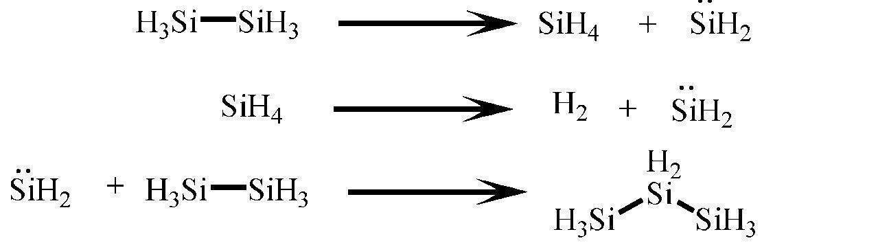
- trisilane is known to decompose into silylene (SiH 2 ) and disilane by pyrolysis as represented by the following formula, but in the presence of excess monosilane, silylene reacts with monosilane and is converted to disilane. can do. That is, it is possible to convert one molecule of trisilane to monosilane as a raw material to convert it into two molecules of disilane, and as a result, it is possible to improve the selectivity of disilane in the reaction.
- the trisilane produced as a by-product is recovered and supplied as a raw material together with monosilane, thereby improving the selectivity of disilane and reusing trisilane. It becomes a very efficient method.
- disilane produced during the reaction may be recovered and used as a raw material together with monosilane.
- Disilane is also known to decompose into silylene and monosilane.
- trisilane is produced by the reaction of monosilane, silylene generated from disilane and disilane to produce a relative selectivity for trisilane. It can be increased.
- the term “used as a raw material” means that it is actively used as a raw material. If a batch reactor is used, it is assumed that a continuous reactor is charged before the reaction. If used, it means intermittent or continuous feeding to the reactor.
- manufacturing method 1 includes step 1-1 and manufacturing method 2 includes step 1-2, from step 1-1 or step 1-2, formula (P-1) or formula (P- Although the specific aspect of the whole "manufacturing method of oligosilane" until isolating the oligosilane represented by 2) is not specifically limited, it can be classified as (A) and (B) below ((B ) Can be classified into (B-1) and (B-2).)
- B Continuous method A method of continuously charging the raw material into the reactor in step 1-1 or 1-2, reaction, and recovery of the reaction product.
- Step 1-1 or step The process 1-2 is continuously performed as (B-2) in which tetrahydrosilane (SiH 4 ) and the like are recovered from the mixture obtained through the process 1-1 or process 1-2 and reused.
- Step 1-1 is characterized by using, as a raw material, an oligosilane represented by the formula (R-1) together with tetrahydrosilane (SiH 4 ).
- an oligosilane represented by the formula (R-1) As the oligosilane represented by the formula (R-1), octasilane Hydrotrisilane (Si 3 H 8 ) is preferably used.
- the usage amount of the oligosilane represented by the formula (R-1) in the step 1-1 is usually 0.001 times or more, preferably 0.003 in terms of mole relative to the usage amount of tetrahydrosilane (SiH 4 ). It is more than twice, more preferably more than 0.005 times, usually 0.5 times or less, preferably 0.3 times or less, more preferably 0.2 times or less. If the amount of oligosilane used is 0.5 times or less of the amount of tetrahydrosilane (SiH 4 ), the number of silicon atoms is larger than the target oligosilane due to the reaction of silylene and oligosilane generated from oligosilane and monosilane. By-product of oligosilane is a low level that does not cause a problem.
- Step 1-2 is characterized by using, as a raw material, an oligosilane represented by the formula (R-2) together with tetrahydrosilane (SiH 4 ).
- an oligosilane represented by the formula (R-2) hexasilane it is preferable to use the hydro disilane (Si 2 H 6).
- the amount of the oligosilane represented by the formula (R-2) in Step 1-2 is usually 0.005 times or more, preferably 0.05 or more in terms of moles relative to the amount of tetrahydrosilane (SiH 4 ). It is more than 1 time, more preferably more than 0.1 time, usually 2 times or less, preferably 1.5 times or less, more preferably 1 time or less.
- the amount of oligosilane used is 0.005 times or more of the amount of tetrahydrosilane (SiH 4 ) used, the reaction efficiency between the generated silylene and oligosilane can be increased, and the number of silicon atoms is increased. effective.
- the by-production of oligosilane having a larger number of silicon atoms than the target oligosilane due to the reaction between silylene generated from oligosilane and monosilane and oligosilane is a low level that does not cause a problem.
- the reaction temperature in the 1-1 and 1-2 steps depends on the operating pressure and residence time, but in the case of no catalyst, it is 300 ° C. or more and 550 ° C. or less, more preferably 400 ° C. or more and 500 ° C. or less. .
- a catalyst is usually 50 ° C. or higher, preferably 100 ° C. or higher, usually 400 ° C. or lower, preferably 350 ° C. or lower, more preferably 300 ° C. or lower.
- oligosilane can be produced more efficiently.
- the conversion rate of the silane and oligosilane used as the raw material is preferably 30% or less, more preferably 20% or less by devising the residence time. Although it is possible to make the conversion rate higher than 30%, if the conversion rate becomes high, oligosilanes with a large molecular weight will be produced sequentially, and if the conversion rate is too high, solid oligosilanes may be produced. Yes, not preferred.
- the residence time is 1 second to 1 hour, more preferably 5 seconds to 30 minutes, and even more preferably 10 seconds to 10 minutes, although it depends on the reaction temperature and whether or not a catalyst is used.
- Step 1-1 and Step 1-2 are preferably carried out in the presence of a catalyst containing a transition element (hereinafter sometimes abbreviated as “catalyst”) from the viewpoint of oligosilane production efficiency.
- a catalyst containing a transition element hereinafter sometimes abbreviated as “catalyst”
- Specific types of transition elements are not particularly limited, but include Group 3 transition elements, Group 4 transition elements, Group 5 transition elements, Group 6 transition elements, Group 7 transition elements, Group 8 transition elements, Examples include Group 9 transition elements, Group 10 transition elements, and Group 11 transition elements.
- Examples of the Group 3 transition element include scandium (Sc), yttrium (Y), lanthanoid (La), and samarium (Sm).
- Examples of Group 4 transition elements include titanium (Ti), zirconium (Zr), and hafnium (Hf).
- Group 5 transition elements include vanadium (V), niobium (Nb), and tantalum (Ta).
- Examples of Group 6 transition elements include chromium (Cr), molybdenum (Mo), and tungsten (W).
- Group 7 transition elements include manganese (Mn), technetium (Tc), and rhenium (Re).
- Group 8 transition elements include iron (Fe), ruthenium (Ru), and osmium (Os).
- Examples of the Group 9 transition element include cobalt (Co), rhodium (Rh), and iridium (Ir).
- Examples of the Group 10 transition element include nickel (Ni), palladium (Pd), and platinum (Pt).
- Examples of the Group 11 transition element include copper (Cu), silver (Ag), and gold (Au).
- a Group 5 transition element, a Group 6 transition element, a Group 7 transition element, a Group 8 transition element, a Group 9 transition element, and a Group 10 transition element are preferable, tungsten (W), Vanadium (V), molybdenum (Mo), cobalt (Co), nickel (Ni), palladium (Pd), and platinum (Pt) are more preferable, and cobalt (Co), tungsten (W), and molybdenum (Mo) are more preferable.
- tungsten (W), Vanadium (V), molybdenum (Mo), cobalt (Co), nickel (Ni), palladium (Pd), and platinum (Pt) are more preferable
- cobalt (Co), tungsten (W), and molybdenum (Mo) are more preferable.
- the catalyst may be either a heterogeneous catalyst or a homogeneous catalyst as long as it contains a transition element, but is preferably a heterogeneous catalyst, particularly a heterogeneous catalyst including a support. preferable.
- the state and composition of the transition element in the catalyst are not particularly limited.
- a heterogeneous catalyst the state of the metal (single metal or alloy) whose surface may be oxidized, the metal oxide (single metal) Oxide, composite metal oxide).
- the transition element is introduced into the carrier skeleton by ion exchange or complexing, which is supported in the form of metal or metal oxide on the outer surface or pores of the carrier.
- an organometallic complex having a transition element as a central metal can be mentioned.
- the metals whose surface may be oxidized include scandium, yttrium, lanthanoid, samarium, titanium, zirconium, hafnium, vanadium, niobium, tantalum, chromium, molybdenum, tungsten, manganese, technetium, rhenium, iron, ruthenium, osmium, cobalt Rhodium, iridium, nickel, palladium, platinum, copper, silver, gold and the like.
- metal oxides include scandium oxide, yttrium oxide, lanthanoid oxide, samarium oxide, titanium oxide, zirconium oxide, hafnium oxide, vanadium oxide, niobium oxide, tantalum oxide, chromium oxide, molybdenum oxide, tungsten oxide, manganese oxide, and technetium oxide. , Rhenium oxide, iron oxide, ruthenium oxide, osmium oxide, cobalt oxide, rhodium oxide, iridium oxide, nickel oxide, palladium oxide, platinum oxide, copper oxide, silver oxide, and composite oxides thereof.
- carrier in case the catalyst is a heterogeneous catalyst containing a support
- carrier is not specifically limited, A silica, an alumina, a zeolite, activated carbon, aluminum phosphate etc. are mentioned. Among these, zeolite is preferable, and zeolite having pores having a minor axis of 0.43 nm or more and a major axis of 0.69 nm or less is particularly preferable.
- the pore space of zeolite is thought to work as a reaction field for dehydrogenative condensation, and the pore size of “minor axis 0.43 nm or more and major axis 0.69 nm or less” suppresses excessive polymerization, and oligosilane It is considered optimal for improving the selectivity.
- zeolite having pores with a minor axis of 0.43 nm or more and a major axis of 0.69 nm or less actually means only zeolites having “minor pores of 0.43 nm or more and major axis of 0.69 nm or less”.
- zeolites that satisfy the above-mentioned conditions in which the “minor axis” and “major axis” of the pores calculated theoretically from the crystal structure respectively.
- the minor axis of the zeolite is 0.43 nm or more, preferably 0.45 nm or more, particularly preferably 0.47 nm or more.
- the major axis of the zeolite is 0.69 nm or less, preferably 0.65 nm or less, particularly preferably 0.60 nm or less.
- the pore diameter of zeolite is considered to be “0.43 nm or more and 0.69 nm or less”.
- the pore diameter of at least one kind of pores may be “0.43 nm or more and 0.69 nm or less”.
- zeolites are the structural codes compiled in the database of the International Zeolite Association, AFR, AFY, ATO, BEA, BOG, BPH, CAN, CON, DFO, EON, EZT, GON. , IMF, ISV, ITH, IWR, IWV, IWW, MEI, MEL, MFI, OBW, MOZ, MSE, MTT, MTW, NES, OFF, OSI, PON, SFF, SFG, STI, STF, TER, TON, TUN , Zeolites corresponding to USI and VET are preferred.
- Structural code is ATO, BEA, BOG, CAN, IMF, ITH, IWR, IWW, MEL, MFI, OBW, MSE, MTW, NES, OSI, PON, SFF, SFG, STF, STI, TER, TON, Zeolite corresponding to TUN and VET is more preferable. Zeolite whose structural code corresponds to BEA, MFI, or TON is particularly preferred.
- Zeolite whose structural code corresponds to BEA is Beta (beta), [B-Si-O] -BEA, [Ga-Si-O] -BEA, [Ti-Si-O] -BEA, Al- rich beta, CIT-6, Tscherichite, pure silica beta, and the like.
- Zeolite whose structural code corresponds to MFI includes ZSM-5, [As-Si-O] -MFI, [Fe-Si-O] -MFI, [Ga-Si-O] -MFI, AMS-1B.
- zeolite whose structural code corresponds to TON include Theta-1, ISI-1, KZ-2, NU-10, ZSM-22 and the like.
- Particularly preferred zeolites are ZSM-5, beta, ZSM-22.
- the silica / alumina ratio is preferably 5 to 10000, more preferably 10 to 2000, and particularly preferably 20 to 1000.
- the content (total content) of transition elements in the catalyst is usually 0. 0 relative to the total mass of the entire catalyst (including the mass of the support in the case of a catalyst including a support). It is 01 mass% or more, preferably 0.1 mass% or more, more preferably 0.5 mass% or more, and is usually 50 mass% or less, preferably 20 mass% or less, more preferably 10 mass% or less. When it is within the above range, oligosilane can be produced more efficiently.
- the catalyst is at least one typical element selected from the group consisting of Group 1 typical elements and Group 2 typical elements (hereinafter referred to as "periodic table Group 1 typical elements"). It may be abbreviated as :)).
- the state and composition of the periodic table Group 1 typical element and the like in the catalyst are not particularly limited, and examples thereof include a state of a metal oxide (single metal oxide, composite metal oxide).
- the catalyst is a heterogeneous catalyst including a carrier, the catalyst is supported in the form of a metal oxide on the outer surface or pores of the carrier, typical of the first group of the periodic table on the carrier skeleton by ion exchange or complexation. Examples include elements into which elements are introduced.
- group 1 typical elements include lithium (Li), sodium (Na), potassium (K), rubidium (Rb), cesium (Cs), and francium (Fr).
- Group 2 typical elements include beryllium (Be), magnesium (Mg), calcium (Ca), strontium (Sr), barium (Ba), and radium (Ra).
- examples of the method for blending the periodic table Group 1 typical elements into the catalyst include an impregnation method and an ion exchange method.
- the impregnation method is a method in which a carrier is brought into contact with a solution in which a periodic table group 1 typical element or the like is dissolved, and the periodic table group 1 typical element or the like is adsorbed on the surface of the carrier.
- the ion exchange method is a method in which a carrier such as zeolite is brought into contact with a solution in which ions such as Group 1 elements of the periodic table are dissolved, and ions such as Group 1 typical elements of the periodic table are introduced into the acid point of the carrier. is there. Moreover, you may perform processes, such as drying and baking, after the impregnation method and the ion exchange method.
- the periodic table group 1 typical element is included, the content (total content) is usually 0.01 relative to the total mass of the entire catalyst (including the mass of the support in the case of a catalyst including a support).
- % By mass or more, preferably 0.05% by mass or more, more preferably 0.1% by mass or more, further preferably 0.5% by mass or more, particularly preferably 1.0% by mass or more, and most preferably 2.1% by mass. %, Usually 10% by mass or less, preferably 5% by mass or less, more preferably 4% by mass or less. When it is within the above range, oligosilane can be produced more efficiently.
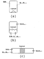
- the reactor is a tank type reactor as shown in FIG. 3A, and in the case of a continuous type, a tank type reactor (fluidized bed) as shown in FIG.
- a tubular reactor fixed bed as shown in 3 (c) is mentioned.
- the operation procedure is represented by tetrahydrosilane (SiH 4 ), formula (R-1), or formula (R-2) after removing the air in the reactor using a vacuum pump or the like.
- a catalyst before removing the air in a reactor, installing the dried catalyst in a reactor is mentioned.
- the catalyst may be a fixed bed type as shown in FIG. 3 (c) or a fluidized bed type as shown in FIG. 3 (b), and an operation procedure based on each method is appropriately adopted. can do.
- a compound other than tetrahydrosilane (SiH 4 ), the oligosilane represented by the formula (R-1) or the formula (R-2) may be charged or passed.
- the compounds other than tetrahydrosilane (SiH 4 ), oligosilane represented by formula (R-1) or formula (R-2) include gases such as hydrogen gas, helium gas, nitrogen gas, and argon gas. In particular, it is preferably carried out in the presence of hydrogen gas.
- the reaction pressure in Step 1-1 and Step 1-2 is usually 0.1 MPa or more in absolute pressure, preferably 0.15 MPa or more, more preferably 0.2 MPa or more, and usually 1000 MPa or less, preferably 500 MPa or less. More preferably, it is 100 MPa or less.
- the partial pressure of hydrosilane is usually 0.0001 MPa or more, preferably 0.0005 MPa or more, more preferably 0.001 MPa or more, and usually 100 MPa or less, preferably 50 MPa or less, more preferably 10 MPa or less. When it is within the above range, oligosilane can be produced more efficiently.
- the partial pressure of hydrogen gas is 0.05 to 5 with respect to the partial pressure of tetrahydrosilane and oligosilane, preferably 0. 1 to 4, more preferably 0.02 to 2 (hydrogen gas / (tetrahydrosilane and oligosilane)).
- step 2 As long as production method 1 includes step 1-1 and production method 2 includes step 1-2, the others are not particularly limited, but are obtained through step 1-1 or step 1-2.
- the mixture is subjected to at least one of the following treatments (i) to (iii) to obtain the formula (P-1) or the formula (P-2) (hereinafter, both formulas are referred to as “formula (P)”)
- a second step (hereinafter sometimes abbreviated as “second step”) including obtaining a liquid containing an oligosilane represented by the following formula.
- (I) Compress and / or cool the mixture.
- tetrahydrasilane, hydrogen gas having a low boiling point, low solubility in the absorption liquid, or low adsorption amount to the adsorbent It becomes easy to separate from such components.
- the component to be in a liquid state and the component to be in a gas state can be appropriately selected.
- the one-pass method and the recycling method the following should be performed. Is preferred. (One pass method) In the case of the one-pass method, the basic unit deteriorates unless the raw material tetrahydrosilane is collected.
- Liquid tetrahydrosilane (SiH 4 ), hexahydrodisilane (Si 2 H 6 ), octahydrotrisilane (Si 3 H 8 ), oligosilane having more silicon atoms than the oligosilane represented by formula (P)
- Gas hydrogen It is desirable to use gas.
- the process (i) is a process for compressing and / or cooling the mixture, but the compression conditions, cooling conditions, etc. should be appropriately selected according to the component to be in a liquid state and the component to be in a gas state. is there.
- the cooling temperature is usually ⁇ 200 ° C. or higher and ⁇ 20 ° C. or lower, preferably ⁇ 180 ° C. or higher and ⁇ 50 ° C. or lower, at normal pressure.
- the process (i) may be performed using a known compression / cooling / condensing type recovery device.
- the treatment (ii) is a treatment in which the mixture is brought into contact with the absorbing liquid, but the temperature of the absorbing liquid and the absorbing liquid should be appropriately selected according to the component in the liquid state and the component in the gas state. It is.
- the absorption liquid for monosilane and oligosilane include silicon hydride compounds such as trisilane and tetrasilane, alkylsilanes such as hexamethyldisilane, saturated hydrocarbons such as hexane, heptane and octane, and aromatic hydrocarbons such as toluene and xylene. It is done.
- the operating temperature is preferably ⁇ 50 ° C.
- the absorbing liquid may be brought into contact with the mixture in a countercurrent manner.
- the treatment of (iii) is a treatment in which the mixture is brought into contact with the adsorbent and then desorbed and compressed and / or cooled.
- the heating temperature, cooling temperature, etc. of the adsorbent and desorption are in a liquid state. It should be appropriately selected depending on the component and the component in the gaseous state.
- Examples of the adsorbent for monosilane and oligosilane include zeolite (natural zeolite, synthetic zeolite), alumina gel, silica gel, activated carbon and the like. Among these, zeolite having a pore (molecular sieve) is preferable. Desorption may be performed by heating, and the heating temperature is usually ⁇ 10 ° C.
- the cooling temperature after desorption is usually ⁇ 50 ° C. or higher and 150 ° C. or lower, preferably ⁇ 15 ° C. or higher and 100 ° C. or lower, at normal pressure. Further, pressurization may be performed at an operating temperature of room temperature or higher.
- the treatment of (iii) can be performed using an adsorption tower.
- the manufacturing method 1 and the manufacturing method 2 are the 3rd process (henceforth the following) including isolate
- the oligosilane represented by the formula (P) is finally isolated through a purification process described later.
- Phase is used again in the first step 1-1 or the first step 1-2 through a fourth step described later.
- the third step may be performed using a gravity separation type device, a surface tension separation type device, or a centrifugal separation type device.
- a gravity separation type device In the case of the recycling method, it is preferable to heat in order to vaporize tetrahydrosilane (SiH 4 ) dissolved in the liquid phase (liquid containing the oligosilane represented by the formula (P)).
- tetrahydrosilane (SiH 4 ) By heating and vaporizing tetrahydrosilane (SiH 4 ), it becomes difficult to condense in a circulation pump (compressor) or the like.
- the heating temperature is usually 30 ° C. or higher and 300 ° C. or lower, preferably 50 ° C. or higher and 150 ° C. or lower.
- the manufacturing method 1 and the manufacturing method 2 include a fourth process (hereinafter referred to as “the second process”) including separating hydrogen gas from the gas (gas phase) obtained through the third process using a hydrogen separation membrane. It may be abbreviated as “4 steps”).
- the hydrogen gas produced as a by-product due to the reaction accumulates, so that the hydrogen gas can be removed as appropriate by including the fourth step.
- the hydrogen separation membrane is a semipermeable membrane that selectively transmits hydrogen gas.
- the semipermeable membrane includes, for example, a dense layer that selectively transmits hydrogen gas and a porous base material that supports the dense layer.
- Examples of the shape of the semipermeable membrane include a flat membrane, a spiral membrane, and a hollow fiber membrane. Among these, a hollow fiber membrane is more preferable.
- Materials used for the dense layer include polyimide, polysiloxane, polysilazane, acrylonitrile, polyester, cellulose polymer, polysulfone, polyalkylene glycol, polyethylene, polybutadiene, polystyrene, polyvinyl halide, polyvinylidene halide, polycarbonate, and any of these A block copolymer having a repeating unit may be mentioned. In addition to those using these polymer materials, those using known materials such as carbon materials and hydrogen-permeable palladium can also be used.
- the production method 1 and the production method 2 include a purification step (hereinafter referred to as “isolating the oligosilane represented by the formula (P)” from the liquid containing the oligosilane represented by the formula (P) obtained through the third step. And may be abbreviated as “purification step”).
- the purification step not only isolates the oligosilane represented by the formula (P), but also from tetrahydrosilane (SiH 4 ), hexahydrodisilane (Si 2 H 6 ), and the oligosilane represented by the formula (P). Alternatively, oligosilane having a large number of silicon atoms may be isolated according to the purpose.
- the method for isolating the oligosilane represented by the formula (P) in the purification step is not particularly limited, and examples include isolating the oligosilane represented by the formula (P) by distillation.
- first step 1-2, second step, third step, fourth step, purification step, temperature and pressure are set for the next step. It may include a heating step for adjusting, a cooling step, a pressurizing step, a depressurizing step, and a filtering step for separating solids.
- the recovered tetrahydrosilane (SiH 4 ) or the like is introduced into the reactor, so that a compressor or the like is used, or tetrahydrosilane (SiH 4 ), formula (R-1) or formula (R— It may be possible to add a raw material such as oligosilane represented by 2).
- Specific embodiments of the batch production method 1 include an embodiment including a first step 1-1, a second step, a third step, and a purification step.
- the 1-1 step may be performed using a batch reactor, and the 2nd step, the 3rd step, the purification step, etc. may be performed using a batch type dedicated apparatus and a dedicated instrument, respectively.
- Examples of the continuous one-pass manufacturing method 1 include an embodiment including a first step 1-1, a second step, a third step, and a purification step.
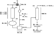
- using an apparatus as represented by FIG. 1 is mentioned. Hereinafter, the configuration of the apparatus of FIG. 1 will be described in detail.
- the source gas is pressurized to a predetermined pressure, preheated, and introduced into the reactor 101 set at a predetermined temperature.
- the gas (mixture) containing the product reacted here is sent to the liquid recovery means 102 that performs the compression / cooling condensation, absorption liquid, or adsorbent treatment step for collecting the next silanes.
- it can be sent to the liquid recovery means 102 through a filter for separating the solid oligosilane in preparation for an abnormal situation.
- the reaction gas temperature is lowered by a heat exchanger or the like. It is better to leave it.
- the compression cryogenic condenser When reacting continuously in one pass, it is better to condense the reaction gas other than hydrogen gas including the raw material monosilane as much as possible, so the compression cryogenic condenser is further pressurized when the reaction pressure is set low. It is preferable to set the temperature to be further lower than the condensation temperature of disilane at the operation pressure while facilitating the condensation.
- the pressure is preferably slightly more than 0.11 MPa, more preferably 0.2 MPa or more, and even more preferably 0.3 MPa or more, which is slightly more pressurized than atmospheric pressure.
- it when absorbing with an absorbent or when treating with an adsorbent, it is basically better to treat at higher pressure and lower temperature.
- the temperature is very high immediately after coming out of the reactor, and therefore it is costly to pre-cool through a plurality of heat exchangers and collect heat energy as much as possible. Is advantageous and preferred.
- the liquid containing the components in the mixture that can be condensed here is separated from uncondensed gas mainly composed of hydrogen gas, and then purified by the distiller 103.
- the purification in the distillation apparatus 103 can be performed by batch operation after accumulating the liquid to some extent, or can be performed by continuous distillation. Since monosilane, disilane, trisilane, tetrasilane, and pentasilane have different boiling points, it is desirable to fractionate the necessary silanes by increasing their purity by precision distillation.
- the manufacturing method 1 of the continuous recycling method includes the 1-1 step, the 2nd step, the 3rd step, the 4th step, and the purification step, and the gas obtained through the 4th step is changed to the 1-1 step.
- purification process with respect to the liquid containing the oligosilane obtained through the 3rd process is mentioned.
- FIG. 2 the configuration of the apparatus of FIG. 2 will be described in detail.
- a filter is installed for separation from the solid oligosilane in order to cope with an abnormal situation as in the one-pass method, or the reaction gas is preliminarily separated from the reaction gas by a heat exchanger. Thermal energy can be recovered during cooling.
- a gas (mixture) containing the product that has been pre-cooled as necessary is sent to a liquid recovery means 202 that performs a compressed deep-cooled condensation, absorption liquid, or adsorbent treatment step for collecting the generated oligosilanes.
- the operating pressure is lower and the cooling temperature is set higher than in the case of the one-pass method.
- the condensate (liquid) condensed by various methods in the liquid recovery means 202 is sent to an evaporator 203 that performs gas-liquid separation.
- it is better to vaporize the dissolved monosilane as much as possible it is vaporized by lowering the operating pressure and sent to the reactor together with uncondensed gas such as hydrogen gas.
- the pressure is increased using a compressor 205 as necessary, and the resultant is sent to the hydrogen separation membrane 204.
- the raw material gas is mixed before the hydrogen separation membrane, but may be added after the separation.
- it is better to adjust the separation conditions in the separation membrane so as to separate only the by-produced hydrogen gas so as to ensure a desired hydrogen gas partial pressure.
- hydrogen gas is added.
- the reaction gas whose raw material gas concentration is adjusted in this way is pressurized and heated as necessary, and sent to the reactor 201.
- the condensate (liquid) separated by the evaporator 203 is sent to a distiller 206 for purifying oligosilanes.
- the distiller 206 is the same as the distiller 103 of the one-pass method. If there is a temporary storage tank for the product, it can be batch-type distilled or purified by continuous distillation.
- Specific embodiments of the batch-type production method 2 include an embodiment including the first-second step, the second step, the third step, and the purification step.
- the first and second steps may be performed using a batch-type reactor, and the second, third, and purification steps may be performed using a batch-type dedicated device and a dedicated instrument, respectively.
- Examples of the continuous one-pass manufacturing method 2 include an embodiment including a first-second step, a second step, a third step, and a purification step. In this aspect, it is possible to use an apparatus as shown in FIG. 1 as described above.
- the production method 2 of the continuous recycling method includes the 1-2 process, the 2nd process, the 3rd process, the 4th process, and the purification process, and the gas obtained through the 4th process is used as the 1-2 process.
- purification process with respect to the liquid containing the oligosilane obtained through the 3rd process is mentioned. In addition, in this aspect, it is mentioned using the apparatus as represented by FIG. 2 as mentioned above.
- H-ZSM-5 (1.0 g) prepared in Preparation Example 1 was placed in a reaction tube (SUS: outer diameter 19.05 mm, thickness 1.24 mm, length 230 mm), and the air in the reaction tube was evacuated using a vacuum pump. After removal, it was replaced with helium gas. Helium gas was circulated at a rate of 20 mL / min, heated to 200 ° C., and then circulated for 1 hour. Thereafter, each mixed gas was adjusted so as to have the reaction gas composition shown in Table 1, and was circulated at a rate of 10 ml / min.
- the composition of the reaction gas after 4 hours was analyzed by gas chromatography (GC-17A, Shimadzu Corporation, detector TCD, analytical column: TC-BOND Q, manufactured by GL Sciences Inc.) to convert monosilane. Rate, yield of disilane and trisilane, and space time yield (STY) of disilane and trisilane were calculated. The results are shown in Table 1. In addition, the yield of disilane and trisilane was calculated by the following calculation formula on the basis of only the monosilane supplied as a raw material on calculation.
- gas chromatography GC-17A, Shimadzu Corporation, detector TCD, analytical column: TC-BOND Q, manufactured by GL Sciences Inc.
- Examples 3 and 4 and Comparative Example 2 The same operation and analysis as in Examples 1 and 2 and Comparative Example 1 were performed except that ZSM-5 loaded with 1% by mass of Mo prepared in Preparation Example 2 was used instead of H-ZSM-5 prepared in Preparation Example 1. . The results are shown in Table 2.
- Examples 1, 3, and 5 were obtained by feeding trisilane.
- the amount of trisilane in the supply gas and the outlet gas composition in the example hardly changed, while the yield of disilane was low. It can be seen that it has improved.
- Examples 2, 4, and 6 are examples in which disilane was fed, but the amount of disilane supplied and the amount of disilane in the outlet gas were almost the same (apparent yield was almost 0%), and the yield of trisilane was improved. You can see that
- the temperature of the catalyst layer is lowered to 150 ° C., and hydrogen gas is supplied through the hydrogen gas flow meter to bring the inside of the reactor system to 0.15 MPa (gauge pressure) in order to use hydrogen gas as the dilution gas during the reaction.
- the pressure was increased while controlling with the pressure regulating valve until it was maintained at a flow rate of 6.5 L / min for 1 hour.
- the monosilane was pressurized from the monosilane container through the monosilane flowmeter at a flow rate of 0.01 L / min with a pressure regulating valve until the pressure in the reactor system reached 0.2 MPa (gauge pressure). I kept it for 47 hours.
- the conversion rate of monosilane calculated from this was 8.2%, the yield of disilane was 5.8%, the yield of trisilane was 2.7%, and it can be seen that the yield of trisilane was improved by feeding disilane. .
- Trisilane was added as a raw material gas together with the monosilane, and the hydrogen gas flow rate, monosilane flow rate, and trisilane flow rate were controlled so that the inlet gas concentrations shown in Table 6 were obtained.
- the raw material gas trisilane was obtained by distilling the reaction liquid extracted from the valve 3.
- the conversion rate of monosilane calculated from this was 6.9%, the conversion rate of trisilane was 36.0%, and the yield of disilane was 5.9%.
- the concentration of trisilane was lower in the outlet gas. It was. Thus, it can be seen that by feeding trisilane, trisilane is decomposed and contributes to the production of disilane.
- the yield of disilane was 5.6% when trisilane was fed to the raw material and calculated according to the following formula.
- the oligosilane production method according to one embodiment of the present invention can improve the selectivity of the target oligosilane and efficiently produce the oligosilane. Further, the disilane obtained by the oligosilane production method according to one embodiment of the present invention can be used as a production gas for silicon for semiconductors, and the productivity and productivity in the semiconductor industry can be improved by improving the yield and selectivity of disilane. Improvement can be expected.
- liquid recovery means compressed deep-cooled condensation, absorbent, or adsorbent
- Distiller 102
- Liquid recovery means compressed cryogenic condensation, absorbent, or adsorbent
- Evaporator gas-liquid separation
- Hydrogen separation membrane 205
- Compressor 206
- Distiller 401
- Reactor 402 Heat exchanger 403
- Cooling trap 404
Landscapes
- Chemical & Material Sciences (AREA)
- Organic Chemistry (AREA)
- Engineering & Computer Science (AREA)
- Chemical Kinetics & Catalysis (AREA)
- Materials Engineering (AREA)
- Crystallography & Structural Chemistry (AREA)
- Inorganic Chemistry (AREA)
- Analytical Chemistry (AREA)
- General Chemical & Material Sciences (AREA)
- Oil, Petroleum & Natural Gas (AREA)
- Silicon Compounds (AREA)
- Catalysts (AREA)
- Nanotechnology (AREA)
Abstract
Description
従来、オリゴシランを製造する方法としては、マグネシウムシリサイドの酸分解法(非特許文献1参照)、ヘキサクロロジシランの還元法(非特許文献2参照)、テトラヒドロシラン(SiH4,以下、「シラン」、「モノシラン」と略す場合がある。)の放電法(特許文献1参照)、シランの熱分解法(特許文献2~4参照)、並びに触媒を用いたシランの脱水素縮合法(特許文献5~10参照)等が報告されている。
本発明は、目的とするオリゴシランを選択的に製造することができるオリゴシランの製造方法を提供することを目的とする。
<1> テトラヒドロシラン(SiH4)を原料として用いて下記式(P-1)で表されるオリゴシランを生成する第1-1工程を含むオリゴシランの製造方法であって、

前記第1-1工程が、テトラヒドロシラン(SiH4)とともに下記式(R-1)で表されるオリゴシランを原料として用いて、下記式(R-1)で表されるオリゴシランから下記式(P-1)で表されるオリゴシランを生成させることを含む工程であることを特徴とする、オリゴシランの製造方法。

<2> 前記式(R-1)で表されるオリゴシランが、オクタヒドロトリシラン(Si3H8)であり、前記式(P-1)で表されるオリゴシランが、ヘキサヒドロジシラン(Si2H6)である、<1>に記載のオリゴシランの製造方法。
<3> テトラヒドロシラン(SiH4)を原料として用いて下記式(P-2)で表されるオリゴシランを生成する第1-2工程を含むオリゴシランの製造方法であって、

前記第1-2工程が、テトラヒドロシラン(SiH4)とともに下記式(R-2)で表されるオリゴシランを原料として用いて、下記式(R-2)で表されるオリゴシランから下記式(P-2)で表されるオリゴシランを生成させることを含む工程であることを特徴とする、オリゴシランの製造方法。

<4> 前記式(R-2)で表されるオリゴシランが、ヘキサヒドロジシラン(Si2H6)であり、前記式(P-2)で表されるオリゴシランが、オクタヒドロトリシラン(Si3H8)である、<3>に記載のオリゴシランの製造方法。
<5> 前記第1-1工程又は前記第1-2工程が、水素ガスの存在下で行われる工程である、<1>~<4>の何れかに記載のオリゴシランの製造方法。
<6> 前記第1-1工程又は前記第1-2工程が、遷移元素を含有する触媒の存在下で行われる工程である、<1>~<5>の何れかに記載のオリゴシランの製造方法。
<7> 前記触媒に含有される遷移元素が、第5族遷移元素、第6族遷移元素、第7族遷移元素、第8族遷移元素、第9族遷移元素、及び第10族遷移元素からなる群から選択される少なくとも1種である、<6>に記載のオリゴシランの製造方法。
<8> 前記触媒が、担体を含む不均一系触媒である、<6>又は<7>に記載のオリゴシランの製造方法。
<9> 前記担体が、シリカ、アルミナ、及びゼオライトからなる群より選択される少なくとも1種である、<8>に記載のオリゴシランの製造方法。
<10> 前記ゼオライトが、短径が0.43nm以上、長径が0.69nm以下の細孔を有する、<9>に記載のオリゴシランの製造方法。
<11> 前記第1-1工程又は前記第1-2工程を経て得られた混合物に対して下記(i)~(iii)の少なくとも1種の処理を行って、式(P-1)又は式(P-2)で表されるオリゴシランを含む液体を得ることを含む第2工程を含む、<1>~<10>の何れかに記載のオリゴシランの製造方法。
(i)前記混合物を圧縮及び/又は冷却する。
(ii)前記混合物を吸収液に接触させる。
(iii)前記混合物を吸着剤に接触させた後、脱着させて、圧縮及び/又は冷却する。
<12> 前記(i)の処理における冷却温度が、-200℃~-20℃である、<11>に記載のオリゴシランの製造方法。
<13> 前記(ii)の処理における吸収液が、水素化ケイ素化合物、飽和炭化水素、及び芳香族炭化水素からなる群より選択される少なくとも1種の液体である、<11>に記載のオリゴシランの製造方法。
<14> 前記(iii)の処理における吸着剤が、ゼオライト(天然ゼオライト、合成ゼオライト)、アルミナゲル、シリカゲル、及び活性炭からなる群より選択される少なくとも1種の固体の吸着剤である、<11>に記載のオリゴシランの製造方法。
<15> 前記第2工程を経て得られた式(P-1)又は式(P-2)で表されるオリゴシランを含む液体を気体(気相)と分離することを含む第3工程を含む、<11>~<14>の何れかに記載のオリゴシランの製造方法。
<16> 前記第3工程を経て得られた気体(気相)から水素分離膜を用いて水素ガスを分離することを含む第4工程を含む、<15>に記載のオリゴシランの製造方法。
<17> 前記第1-1工程又は前記第1-2工程を1回のみ行うワンパス方式である、<1>~<16>の何れかに記載のオリゴシランの製造方法。
<18> 前記第1-1工程において未反応のテトラヒドロシラン(SiH4)及び式(R-1)で表されるオリゴシランの少なくとも一部を原料として再供給(再利用)するリサイクル方式である、<16>に記載のオリゴシランの製造方法。
<19> 前記第1-2工程において未反応のテトラヒドロシラン(SiH4)及び式(R-2)で表されるオリゴシランの少なくとも一部を原料として再供給(再利用)するリサイクル方式である、<16>に記載のオリゴシランの製造方法。




本発明者らは、テトラヒドロシラン(SiH4)[モノシラン]のみならず、目的とするオリゴシランに対してケイ素原子数が少ないオリゴシランや反対にケイ素原子数が多いオリゴシランを原料として利用することにより、目的とするオリゴシランの選択率を向上させて、オリゴシランを効率良く製造することができることを見出したのである。
例えばトリシランは、下記式で表されるように熱分解によってシリレン(SiH2)とジシランに分解することが知られているが、過剰のモノシラン存在下では、シリレンはモノシランと反応してジシランに変換することができる。つまり、トリシラン1分子から原料のモノシランも加えて、2分子のジシランに変換させることが可能になり、結果的に反応におけるジシランの選択率を向上させることが可能になる。
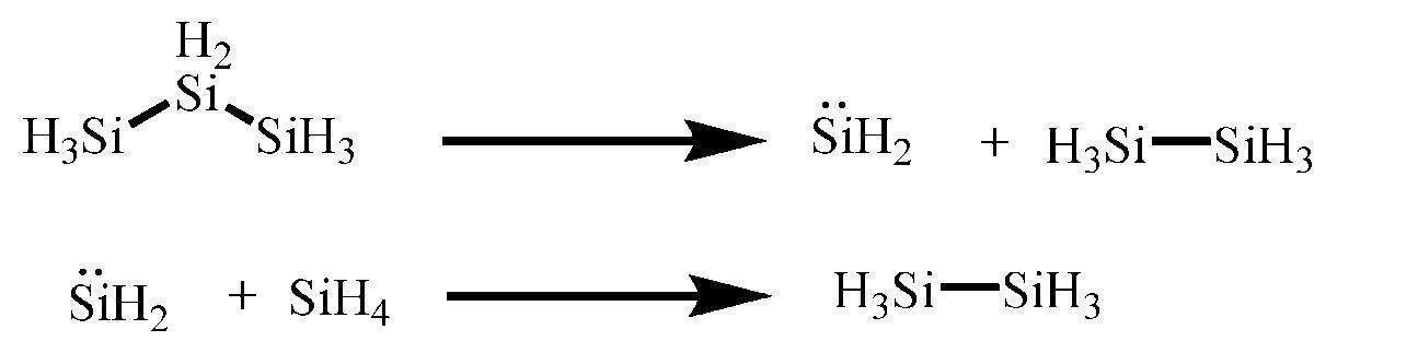
また、現時点ではトリシランの需要はほとんどないが、今後需要が伸びた場合に、反応中に生成するジシランを回収して、モノシランとともに原料として利用すればよい。ジシランもシリレンとモノシランに分解することが知られているがジシランの存在量が多ければ、モノシラン、ジシランから生じるシリレンとジシランが反応してトリシランが生成することにより、相対的にトリシランの選択率を高めることができるのである。
(A)回分式・・・第1-1工程又は第1-2工程における原料の反応器への投入、反応、反応生成物の回収をそれぞれ独立して行う方式
(B)連続式・・・第1-1工程又は第1-2工程における原料の反応器への投入、反応、反応生成物の回収を連続的に行う方式
(B-1)ワンパス方式・・・第1-1工程又は第1-2工程を、第1-1工程又は第1-2工程を経て得られた混合物からテトラヒドロシラン(SiH4)等を回収して再使用することを(B-2)のように連続的に行わず、別工程として行う方式
(B-2)リサイクル方式・・・第1-1工程又は第1-2工程を経て得られた混合物からテトラヒドロシラン(SiH4)や反応に用いることのできるオリゴシラン類等の全部または一部を回収し、残りの反応ガスを単離せずにガス状でそのまま反応器に再度投入して、第1-1工程又は第1-2工程を連続的に行う方式
「テトラヒドロシラン(SiH4)等」とは、テトラヒドロシラン(SiH4)の他に少量のオリゴシランを含むことを意味する。
以下、「第1-1工程」、「第1-2工程」、その他の工程等について、詳細に説明する。
第1-1工程は、テトラヒドロシラン(SiH4)とともに式(R-1)で表されるオリゴシランを原料として用いることを特徴とするが、式(R-1)で表されるオリゴシランとして、オクタヒドロトリシラン(Si3H8)を用いることが好ましい。
第3族遷移元素としては、スカンジウム(Sc)、イットリウム(Y)、ランタノイド(La)、サマリウム(Sm)等が挙げられる。
第4族遷移元素としては、チタン(Ti)、ジルコニウム(Zr)、ハフニウム(Hf)が挙げられる。
第5族遷移元素としては、バナジウム(V)、ニオブ(Nb)、タンタル(Ta)が挙げられる。
第6族遷移元素としては、クロム(Cr)、モリブデン(Mo)、タングステン(W)が挙げられる。
第7族遷移元素としては、マンガン(Mn)、テクネチウム(Tc)、レニウム(Re)が挙げられる。
第8族遷移元素としては、鉄(Fe)、ルテニウム(Ru)、オスミウム(Os)が挙げられる。
第9族遷移元素としては、コバルト(Co)、ロジウム(Rh)、イリジウム(Ir)が挙げられる。
第10族遷移元素としては、ニッケル(Ni)、パラジウム(Pd)、白金(Pt)が挙げられる。
第11族遷移元素としては、銅(Cu)、銀(Ag)、金(Au)が挙げられる。
これらの遷移元素の中でも、第5族遷移元素、第6族遷移元素、第7族遷移元素、第8族遷移元素、第9族遷移元素、第10族遷移元素が好ましく、タングステン(W)、バナジウム(V)、モリブデン(Mo)、コバルト(Co)、ニッケル(Ni)、パラジウム(Pd)、白金(Pt)がより好ましく、コバルト(Co)、タングステン(W)、モリブデン(Mo)がさらに好ましい。
なお、触媒における遷移元素の状態や組成も特に限定されないが、例えば不均一系触媒の場合、表面が酸化されていてもよい金属(単体金属、合金)の状態、金属酸化物(単一の金属酸化物、複合金属酸化物)の状態が挙げられる。また、触媒が担体を含む不均一系触媒の場合、担体の外表面や細孔内に金属や金属酸化物の状態で担持されているもの、イオン交換や複合化で担体骨格に遷移元素が導入されたものが挙げられる。
一方、均一系触媒の場合、遷移元素を中心金属とする有機金属錯体が挙げられる。
表面が酸化されていてよい金属としては、スカンジウム、イットリウム、ランタノイド、サマリウム、チタン、ジルコニウム、ハフニウム、バナジウム、ニオブ、タンタル、クロム、モリブデン、タングステン、マンガン、テクネチウム、レニウム、鉄、ルテニウム、オスミウム、コバルト、ロジウム、イリジウム、ニッケル、パラジウム、白金、銅、銀、金等が挙げられる。
金属酸化物としては、酸化スカンジウム、酸化イットリウム、酸化ランタノイド、酸化サマリウム、酸化チタン、酸化ジルコニム、酸化ハフニウム、酸化バナジウム、酸化ニオブ、酸化タンタル、酸化クロム、酸化モリブデン、酸化タングステン、酸化マンガン、酸化テクネチウム、酸化レニウム、酸化鉄、酸化ルテニウム、酸化オスミウム、酸化コバルト、酸化ロジウム、酸化イリジウム、酸化ニッケル、酸化パラジウム、酸化白金、酸化銅、酸化銀および、これらの複合酸化物等が挙げられる。
なお、「短径0.43nm以上、長径0.69nm以下の細孔を有するゼオライト」は、実際に「短径0.43nm以上、長径0.69nm以下の細孔」を有するゼオライトのみを意味するものではなく、結晶構造から理論的に計算された細孔の「短径」と「長径」がそれぞれ前述の条件を満たすゼオライトも含まれるものとする。ちなみに細孔の「短径」と「長径」については、「ATLAS OF ZEOLITE FRAMEWORK TYPES, Ch. Baerlocher, L.B.McCusker and D.H. Olson, Sixth Revised Edition 2007,published on behalf of the structure Commission of the international Zeolite Association」を参考にすることができる。
ゼオライトの短径は、0.43nm以上、好ましくは0.45nm以上、特に好ましくは0.47nm以上である。
ゼオライトの長径は、0.69nm以下、好ましくは0.65nm以下、特に好ましくは0.60nm以下である。
なお、細孔の断面構造が円形であること等によってゼオライトの細孔径が一定である場合には、細孔径が「0.43nm以上0.69nm以下」であるものと考える。
複数種類の細孔径を有するゼオライトの場合は、少なくとも1種類の細孔の細孔径が「0.43nm以上0.69nm以下」であればよい。
構造コ-ドが、ATO、BEA、BOG、CAN、IMF、ITH、IWR、IWW、MEL、MFI、OBW、MSE、MTW、NES、OSI、PON、SFF、SFG、STF、STI、TER、TON、TUN、VETに該当するゼオライトがより好ましい。
構造コ-ドが、BEA、MFI、TON、に該当するゼオライトが特に好ましい。
構造コ-ドがBEAに該当するゼオライトとしては、Beta(ベータ)、[B-Si-O]-BEA、[Ga-Si-O]-BEA、[Ti-Si-O]-BEA、Al-rich beta、CIT-6、Tschernichite、pure silica beta等を挙げられる。
構造コ-ドがMFIに該当するゼオライトとしては、ZSM-5、[As-Si-O]-MFI、[Fe-Si-O]-MFI、[Ga-Si-O]-MFI、AMS-1B、AZ-1、Bor-C、Boralite C、Encilite、FZ-1、LZ-105、Monoclinic H-ZSM-5、Mutinaite、NU-4、NU-5、Silicalite、TS-1、TSZ、TSZ-III、TZ-01、USC-4、USI-108、ZBH、ZKQ-1B、ZMQ-TB、organic-free ZSM-5等が挙げられる。
構造コ-ドがTONに該当するゼオライトとしては、Theta-1、ISI-1、KZ-2、NU-10、ZSM-22等が挙げられる。
特に好ましいゼオライトは、ZSM-5、ベータ、ZSM-22である。
シリカ/アルミナ比(モル/モル比)としては、5~10000が好ましく、10~2000がより好ましく、20~1000が特に好ましい。
第1族典型元素としては、リチウム(Li)、ナトリウム(Na)、カリウム(K)、ルビジウム(Rb)、セシウム(Cs)、フランシウム(Fr)が挙げられる。
第2族典型元素としては、ベリリウム(Be)、マグネシウム(Mg)、カルシウム(Ca)、ストロンチウム(Sr)、バリウム(Ba)、ラジウム(Ra)が挙げられる。
この中でも、ナトリウム(Na)、カリウム(K)、ルビジウム(Rb)、セシウム(Cs)、フランシウム(Fr)、カルシウム(Ca)、ストロンチウム(Sr)、バリウム(Ba)を含有することが好ましい。
触媒が担体を含む不均一系触媒の場合、触媒への周期表第1族典型元素等の配合方法としては、含浸法、イオン交換法等が挙げられる。なお、含浸法は、周期表第1族典型元素等が溶解した溶液に担体を接触させて、周期表第1族典型元素等を担体表面に吸着させる方法である。また、イオン交換法は、周期表第1族元素等のイオンが溶解した溶液にゼオライト等の担体を接触させて、担体の酸点に周期表第1族典型元素等のイオンを導入する方法である。また、含浸法、イオン交換法の後に、乾燥、焼成等の処理を行ってもよい。
周期表第1族典型元素等を含有させる場合その含有量(総含有量)は、触媒全体の総質量(担体を含む触媒の場合は担体の質量も含む。)に対して、通常0.01質量%以上、好ましくは0.05質量%以上、より好ましくは0.1質量%以上、さらに好ましくは0.5質量%以上、特に好ましくは1.0質量%以上、最も好ましくは2.1質量%以上であり、通常10質量%以下、好ましくは5質量%以下、より好ましくは4質量%以下である。上記範囲内であると、より効率良くオリゴシランを製造することができる。
反応器は、回分式の場合、図3(a)に示されるような槽型反応器を、連続式の場合、図3(b)に示されるような槽型反応器(流動床)や図3(c)に示されるような管型反応器(固定床)を使用することが挙げられる。
一方、連続式の場合、反応器内の空気を減圧ポンプ等を利用して除去した後、テトラヒドロシラン(SiH4)、式(R-1)又は式(R-2)で表されるオリゴシラン等を流通させ、反応器内を反応温度まで昇温して反応を開始する方法が挙げられる。また、触媒を用いる場合、反応器内の空気を除去する前に、乾燥させた触媒を反応器内に設置することが挙げられる。触媒は図3(c)に示されるような固定床式であっても、図3(b)に示されるような流動床式であってもよく、それぞれの方式に基づいた操作手順を適宜採用することができる。
第1-1工程及び第1-2工程が水素ガスの存在下で行われる場合の水素ガスの分圧は、テトラヒドロシランおよびオリゴシランの分圧に対して、0.05~5、好ましくは0.1~4、より好ましくは0.02~2(水素ガス/(テトラヒドロシランおよびオリゴシラン))である。
製造方法1は第1-1工程を、製造方法2は第1-2工程を含むものであれば、その他については特に限定されないが、第1-1工程又は第1-2工程を経て得られた混合物に対して下記(i)~(iii)の少なくとも1種の処理を行って、式(P-1)又は式(P-2)(以下、両式をあわせて「式(P)」と表記する。)で表されるオリゴシランを含む液体を得ることを含む第2工程(以下、「第2工程」と略す場合がある。)を含むことが挙げられる。
(i)前記混合物を圧縮及び/又は冷却する。
(ii)前記混合物を吸収液に接触させる。
(iii)前記混合物を吸着剤に接触させた後、脱着させて、圧縮及び/又は冷却する。
第1-1工程又は第1-2工程を経て得られた混合物には、水素ガス、テトラヒドロシラン(SiH4)、式(P)で表されるオリゴシラン以外に、式(P)で表されるオリゴシランよりもケイ素原子数が多いオリゴシラン(ケイ素原子数≧6)も含まれると考えられる。第2工程によって式(P)で表されるオリゴシランを液体の状態とすることで、沸点が低い、吸収液への溶解性が低い、又は吸着剤への吸着量が低いテトラヒドラシラン、水素ガス等の成分と分離し易くなるのである。
なお、(i)~(iii)の処理条件によって、液体の状態とする成分と気体の状態とする成分を適宜選択することができるが、ワンパス方式、リサイクル方式の場合は下記のようにすることが好ましい。
(ワンパス方式)
ワンパス方式の場合には、原料のテトラヒドロシランを捕集しないと原単位が悪化するので、
液体:テトラヒドロシラン(SiH4)、ヘキサヒドロジシラン(Si2H6)、オクタヒドロトリシラン(Si3H8)、式(P)で表されるオリゴシランよりもケイ素原子数が多いオリゴシラン
気体:水素ガス
とすることが望ましい。
(リサイクル方式)
リサイクルする場合には、低沸点原料のテトラヒドロシランをエネルギーをかけて液状で捕捉するよりも、そのまま使用したほうが効率的であるので、
液体:ヘキサヒドロジシラン(Si2H6)、オクタヒドロトリシラン(Si3H8)、式(P)で表されるオリゴシランよりもケイ素原子数が多いオリゴシラン
気体:テトラヒドロシラン(SiH4)、水素ガス
とすることが望ましい。
以下、「(i)の処理」、「(ii)の処理」、「(iii)の処理」等について詳細に説明する。
冷却温度としては、常圧の場合、通常-200℃以上-20℃以下、好ましくは-180℃以上-50℃以下である。
(i)の処理は、公知の圧縮深冷凝縮方式の回収装置を利用して行うことが挙げられる。
モノシラン、オリゴシランの吸収液としては、トリシラン、テトラシラン等の水素化ケイ素化合物、ヘキサメチルジシラン等のアルキルシラン類、ヘキサン、ヘプタン、オクタン等の飽和炭化水素、トルエン、キシレン等の芳香族炭化水素が挙げられる。
操作温度としては、-50℃以上で操作圧力での溶媒の沸点以下、より好ましくは-20℃以上で操作圧力での溶媒の沸点より10℃低い温度以下が好ましい。温度を低くしすぎる場合にはエネルギーコストが非常にかかり、吸収液を用いるよりも直接凝縮させる方が有利になる。また、温度が高いと吸収液に効率よく溶解させることが出来ない。
混合物を吸収液に接触させる方法は、例えば連続式である場合、吸収液を混合物と向流で接触させることが挙げられる。
モノシラン、オリゴシランの吸着剤としては、ゼオライト(天然ゼオライト、合成ゼオライト)、アルミナゲル、シリカゲル、活性炭等が挙げられる。これらの中でも細孔を有するゼオライト(モレキュラーシーブ)が好ましい。
脱着は、加熱することによって行うことが挙げられ、加熱温度としては、通常-10℃以上200℃以下、好ましくは20℃以上150℃以下である。
脱着後の冷却温度は、常圧の場合、通常-50℃以上150℃以下、好ましくは-15℃以上100℃以下である。また加圧にして、操作温度を室温以上で行っても良い。
(iii)の処理は、吸着塔を利用して行うことが挙げられる。
製造方法1及び製造方法2は、第2工程を経て得られた式(P)で表されるオリゴシランを含む液体(液相)を気体(気相)と分離することを含む第3工程(以下、「第2工程」と略す場合がある。)を含むことが挙げられる。
式(P)で表されるオリゴシランを含む液体は、後述する精製工程等を経て最終的に式(P)で表されるオリゴシランを単離することになる一方、リサイクル方式の場合、気体(気相)は後述する第4工程等を経て再度第1-1工程又は第1-2工程に利用することになる。
リサイクル方式の場合、液相(式(P)で表されるオリゴシランを含む液体)に溶解したテトラヒドロシラン(SiH4)を気化させるために加熱することが好ましい。テトラヒドロシラン(SiH4)を加熱気化させることによって、循環ポンプ(コンプレッサー)等において凝縮し難くなる。
加熱温度は、通常30℃以上300℃以下、好ましくは50℃以上150℃以下である。
リサイクル方式の場合、製造方法1及び製造方法2は、第3工程を経て得られた気体(気相)から水素分離膜を用いて水素ガスを分離することを含む第4工程(以下、「第4工程」と略す場合がある。)を含むことが挙げられる。
リサイクル方式の場合、反応によって副生する水素ガスが蓄積していくため、第4工程を含むことによって、水素ガスを適宜除去することができる。
水素分離膜は、水素ガスを選択的に透過させる半透膜である。半透膜は、例えば水素ガスを選択的に透過させる緻密層と、緻密層を支持する多孔質性の基材とを含む。半透膜の形状としては、平膜、スパイラル膜、中空糸膜が挙げられるが、このうち、中空糸膜がより好ましい。緻密層に用いられる材料としては、ポリイミド、ポリシロキサン、ポリシラザン、アクリロニトリル、ポリエステル、セルロースポリマー、ポリスルホン、ポリアルキレングリコール、ポリエチレン、ポリブタジエン、ポリスチレン、ポリビニルハライド、ポリビニリデンハライド、ポリカーボネートおよびこのうちのいずれかの繰り返し単位を有するブロックコポリマーが挙げられる。これらの高分子材料を用いたもの以外に、炭素材料、水素透過性のあるパラジウム等の公知の材料を用いたものを使用することもできる。
製造方法1及び製造方法2は、第3工程を経て得られた式(P)で表されるオリゴシランを含む液体から式(P)で表されるオリゴシランを単離することを含む精製工程(以下、「精製工程」と略す場合がある。)を含むことが挙げられる。なお、精製工程は、式(P)で表されるオリゴシランを単離するのみならず、テトラヒドロシラン(SiH4)、ヘキサヒドロジシラン(Si2H6)、式(P)で表されるオリゴシランよりもケイ素原子数が多いオリゴシラン等をそれぞれ目的に応じて単離するものであってもよい。
精製工程における式(P)で表されるオリゴシランを単離する方法は、特に限定されないが、蒸留によって式(P)で表されるオリゴシランを単離することが挙げられる。
連続式のワンパス方式の製造方法1としては、第1-1工程、第2工程、第3工程、及び精製工程を含む態様が挙げられる。なお、かかる態様では、図1で表されるような装置を利用することが挙げられる。以下、図1の装置の構成を詳細に説明する。
まず、原料ガスを所定の圧力まで昇圧、予熱して、所定の温度に設定された反応器101に導入する。ここで反応させた生成物を含むガス(混合物)を次のシラン類を捕集する圧縮深冷凝縮、吸収液、又は吸着剤処理工程を行う液体回収手段102に送る。この際に異常時に備えて固体状オリゴシランを分離するためのフィルターを通して液体回収手段102に送ることもできるし、この場合、より有効的に凝縮するために、熱交換器等で反応ガス温度を下げておいた方がよい。ワンパスで連続的に反応させる場合には、水素ガス以外の反応ガスは原料のモノシランも含めて極力凝縮した方がよいので、圧縮深冷凝縮器は反応圧力を低く設定した場合にはさらに加圧し、より凝縮しやすくするとともに操作圧力でのジシランの凝縮温度よりもさらに低く設定しておくことが好ましい。大気圧より多少微加圧である0.11MPa以上であることが好ましく、0.2MPa以上であることがより好ましく、0.3MPa以上であることがさらに好ましい。
吸収液で吸収する場合や吸着剤で処理する場合も基本的には同様に、より高圧、低温で処理したほうがよい。また、いずれの場合も反応器から出てきた直後は非常に高温であるので、複数の熱交換器を通して予備冷却し、その際に可能な限り熱エネルギーを回収しておくことが、コスト的には有利であり好ましい。
ここで凝縮出来た混合物中の成分を含む液体は、水素ガスが主体の未凝縮ガスと分離した後、蒸留器103で精製を行う。蒸留器103での精製は、上記液体をある程度蓄積した後、回分操作で行うこともできるし、連続的に蒸留して行ってもよい。モノシラン、ジシラン、トリシラン、テトラシラン、ペンタシランは沸点差があるので、必要なシラン類については精密蒸留によりそれぞれの純度を高めて分留することが望ましい。
まず、リサイクルガスと新たに投入する原料ガスを所定の混合比となるように混合した後に、必要に応じて昇圧、予備加熱を行った後に所定の温度に設定した反応器201に導入する。反応器から出てきた生成物を含むガス(混合物)については、ワンパス法と同様に異常時対応のために固体オリゴシランとの分離のためにフィルターを設置したり、熱交換器により反応ガスから予備冷却もかねて熱エネルギーを回収することができる。必要に応じて予備冷却を行った生成物を含むガス(混合物)を、生成したオリゴシラン類を捕集する圧縮深冷凝縮、吸収液、又は吸着剤処理工程を行う液体回収手段202に送る。ここで、リサイクルを行う場合には原料のモノシランは凝縮させずに、生成してくるオリゴシラン類のみを凝縮することが望ましいので、ワンパス方式の場合よりは、操作圧力は低く、冷却温度は高く設定する。
ただし、オリゴシラン類にモノシランガスはある程度溶解してしまうので、液体回収手段202で種々の方法により凝縮した凝縮液(液体)を気液分離を行う蒸発器203に送る。ここで、溶解したモノシランは出来るだけ気化させた方がよいので、操作圧力を下げて気化させて水素ガスをはじめとする未凝縮ガスとともに反応器に送る。なお、モノシランガスの回収を高くしようとするとジシラン、トリシランも同伴されて気化してしまうので、実際の操作条件は許容されるモノシランのロス率、ジシラン、トリシラン等のオリゴシランの同伴率を加味しながら決める必要がある。このようにリサイクルさせるガス中のモノシラン、ジシラン、トリシランの濃度を分析し、反応させるために不足する原料ガスを追添する。なお、ジシランやトリシランを原料に用いるので、凝集-蒸発器操作をうまく行えば、更に追添する量を抑えたり、追添する操作を省略することもできる。原料ガスを混合後、必要に応じてコンプレッサー205を用いて昇圧して水素分離膜204に送る。なお、シラン類の濃度によっては昇圧時に凝縮しないように予熱しておいた方がよい。
図2の例示では水素分離膜前に原料ガスを混合することとしたが、分離後に追添してもよい。
なお、反応器に水素ガスを導入する場合には、分離膜での分離条件を調整して、副生する水素ガスのみを分離して所望の水素ガス分圧を確保できるようにした方がよいが、水素ガス濃度が不足するようなら水素ガスを追添する。
このようにして原料ガス濃度を調整した反応ガスを必要に応じて昇圧、昇温して反応器201に送る。
一方、蒸発器203で分離した凝縮液(液体)のほうは、オリゴシラン類を精製する蒸留器206に送る。蒸留器206についてはワンパス法の蒸留器103と同様であり、生成物の一時貯蔵タンクがあれば、バッチ式の蒸留もできるし連続蒸留により精製することもできる。
連続式のワンパス方式の製造方法2としては、第1-2工程、第2工程、第3工程、及び精製工程を含む態様が挙げられる。なお、かかる態様では、前述したような図1で表されるような装置を利用することが挙げられる。
連続式のリサイクル方式の製造方法2としては、第1-2工程、第2工程、第3工程、第4工程、及び精製工程を含み、第4工程を経て得られた気体を第1-2工程に用い、さらに第3工程を経て得られたオリゴシランを含む液体に対して精製工程を行う態様が挙げられる。なお、かかる態様では、前述したような図2で表されるような装置を利用することが挙げられる。
NH4-ZSM-5(シリカ/アルミナ比=23、東ソー製:製品名 HSZ-800タイプ820NHA)20gを110℃で2時間乾燥させた後、700℃で2時間焼成して、粉体状の遷移元素非含有のH-ZSM-5を得た。
NH4-ZSM-5(シリカ/アルミナ比=23、東ソー製:製品名 HSZ-800タイプ820NHA)20gに、蒸留水20g、(NH4)6Mo7O24・4H2O 0.37g(Mo換算で1質量%担持に相当)を加えて、室温で1時間混合した。その後、110℃で2時間乾燥させた後、700℃で2時間焼成して、粉体状のMo1質量%担持ZSM-5を得た。
NH4-ZSM-5(シリカ/アルミナ比=23、東ソー製:製品名 HSZ-800タイプ820NHA)20gに、蒸留水20g、Co(NO3)・6H2O 0.99g(Co換算で1質量%担持に相当)を加えて、室温で1時間混合した。その後、110℃で2時間乾燥させた後、700℃で2時間焼成して、粉体状のCo1質量%担持ZSM-5を得た。
調製例1で調製したH-ZSM-5 1.0gを反応管(SUS製:外径19.05mm、厚み1.24mm、長さ230mm)に設置し、減圧ポンプを使って反応管内の空気を除去した後、ヘリウムガスで置換した。ヘリウムガスを20mL/分の速度で流通させ、200℃に昇温後、1時間流通させた。その後、表1に記載の反応ガス組成になるように、それぞれ混合ガスを調整して10ml/分となる速度で流通させた。表1に示すように4時間経過後の反応ガスの組成をガスクロマトグラフィ(島津社製 GC-17A、検出器 TCD、分析カラム:GLサイエンス社製 TC-BOND Q)でそれぞれ分析し、モノシランの転化率、ジシラン、トリシランの収率、ジシラン、トリシランの空時収率(STY)を算出した。結果を表1に示す。
なお、ジシラン、トリシランの収率は、計算上は原料として供給したモノシランのみの基準として以下の計算式で計算した。


調製例1で調製したH-ZSM-5の代わりに調製例2で調製したMo1質量%担持ZSM-5を使用した以外は、実施例1、2、比較例1同様の操作、分析を行った。結果を表2に示す。

調製例1で調製したH-ZSM-5の代わりに調製例3で調製したCo1質量%担持ZSM-5 1.0gを使用した以外は、実施例1、2、比較例1同様の操作、分析を行った。結果を表3に示す。

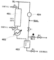
図4に示すリサイクル実験機を用いて、反応ガスの循環実験を行った。
調製例3で調製したCo1質量%担持ZSM-5 500gを反応器401に充填し、図示しない減圧ポンプを使って反応管内の空気を除去した後、窒素ガスで置換した。弁1、弁3、弁4、弁5は閉、弁2を開として、図中には表示していないが水素ガス導入ラインと同じ位置(横)にある窒素ガス導入ラインから窒素ガスを100mL/分の速度で流通させながら、触媒層の温度を400℃に昇温後、1日流通させた。
その後、触媒層の温度を150℃に降温し、反応時の希釈ガスを水素ガスとするために、水素ガス流量計を介して水素ガスで反応器系内が0.15MPa(ゲージ圧)となるまで調圧弁によりコントロールしながら昇圧し、6.5L/分の流量で1時間保持した。さらにモノシランは、モノシラン容器からモノシラン流量計を介して0.01L/分の流量で調圧弁によりコントロールしながら反応器系内の圧力が0.2MPa(ゲージ圧)となるまで昇圧し、この状態で47時間保った。
この後、弁1は閉、弁2は開のまま、熱交換器402に5℃の冷却水を流し、冷却トラップ403を-80℃に冷却し、水素ガス流量を6.5L/分、モノシラン流量3.5L/分とし、2時間反応を行った。この場合には入口ガス濃度はモノシラン35モル%、水素ガス65モル%であり、弁4より排出した反応器出口ガスを分析すると、モノシラン31.7モル%、ジシラン1.13モル%、トリシラン0.227モル%であった。これから計算したモノシランの転化率は9.4%、ジシランの収率は6.5%、トリシランの収率は1.9%であった。
次に弁2開、調圧弁のコントロール圧力0.2MPaのまま、弁1を開にし、冷却トラップでトラップされなかったモノシラン、オリゴシラン類が循環できるようにするとともに、弁5より導入される入口ガスを分析しながら、表4に記載の入口ガス濃度になるように、上記反応に伴い消費された、循環(リサイクル)ガス中に含まれるモノシランでは不足する分のモノシランを原料ガスとして追加し、水素ガス流量、モノシラン流量、ジシラン流量をコントロールした。原料ガスのジシランは、弁3より抜き出した反応液を蒸留して得たものを使用した。

この条件で2時間反応を行った場合の弁4より抜き出した出口ガス組成の分析結果は、表5に記載の通りであった。


なお、参考のためにジシランの収率は、原料にトリシランをフィードしたので、それを考慮した次式で算出すると、5.6%であった。

102 液体回収手段(圧縮深冷凝縮、吸収液、又は吸着剤)
103 蒸留器
201 反応器
202 液体回収手段(圧縮深冷凝縮、吸収液、又は吸着剤)
203 蒸発器(気液分離)
204 水素分離膜
205 コンプレッサー
206 蒸留器
401 反応器
402 熱交換器
403 冷却トラップ
404 コンプレッサー
Claims (19)
- テトラヒドロシラン(SiH4)を原料として用いて下記式(P-1)で表されるオリゴシランを生成する第1-1工程を含むオリゴシランの製造方法であって、

前記第1-1工程が、テトラヒドロシラン(SiH4)とともに下記式(R-1)で表されるオリゴシランを原料として用いて、下記式(R-1)で表されるオリゴシランから下記式(P-1)で表されるオリゴシランを生成させることを含む工程であることを特徴とする、オリゴシランの製造方法。

- 前記式(R-1)で表されるオリゴシランが、オクタヒドロトリシラン(Si3H8)であり、前記式(P-1)で表されるオリゴシランが、ヘキサヒドロジシラン(Si2H6)である、請求項1に記載のオリゴシランの製造方法。
- テトラヒドロシラン(SiH4)を原料として用いて下記式(P-2)で表されるオリゴシランを生成する第1-2工程を含むオリゴシランの製造方法であって、

前記第1-2工程が、テトラヒドロシラン(SiH4)とともに下記式(R-2)で表されるオリゴシランを原料として用いて、下記式(R-2)で表されるオリゴシランから下記式(P-2)で表されるオリゴシランを生成させることを含む工程であることを特徴とする、オリゴシランの製造方法。

- 前記式(R-2)で表されるオリゴシランが、ヘキサヒドロジシラン(Si2H6)であり、前記式(P-2)で表されるオリゴシランが、オクタヒドロトリシラン(Si3H8)である、請求項3に記載のオリゴシランの製造方法。
- 前記第1-1工程又は前記第1-2工程が、水素ガスの存在下で行われる工程である、請求項1~4の何れかに1項に記載のオリゴシランの製造方法。
- 前記第1-1工程又は前記第1-2工程が、遷移元素を含有する触媒の存在下で行われる工程である、請求項1~5の何れか1項に記載のオリゴシランの製造方法。
- 前記触媒に含有される遷移元素が、第5族遷移元素、第6族遷移元素、第7族遷移元素、第8族遷移元素、第9族遷移元素、及び第10族遷移元素からなる群から選択される少なくとも1種である、請求項6に記載のオリゴシランの製造方法。
- 前記触媒が、担体を含む不均一系触媒である、請求項6又は7に記載のオリゴシランの製造方法。
- 前記担体が、シリカ、アルミナ、及びゼオライトからなる群より選択される少なくとも1種である、請求項8に記載のオリゴシランの製造方法。
- 前記ゼオライトが、短径が0.43nm以上、長径が0.69nm以下の細孔を有する、請求項9に記載のオリゴシランの製造方法。
- 前記第1-1工程又は前記第1-2工程を経て得られた混合物に対して下記(i)~(iii)の少なくとも1種の処理を行って、式(P-1)又は式(P-2)で表されるオリゴシランを含む液体を得ることを含む第2工程を含む、請求項1~10の何れか1項に記載のオリゴシランの製造方法。
(i)前記混合物を圧縮及び/又は冷却する。
(ii)前記混合物を吸収液に接触させる。
(iii)前記混合物を吸着剤に接触させた後、脱着させて、圧縮及び/又は冷却する。 - 前記(i)の処理における冷却温度が、-200℃~-20℃である、請求項11に記載のオリゴシランの製造方法。
- 前記(ii)の処理における吸収液が、水素化ケイ素化合物、飽和炭化水素、及び芳香族炭化水素からなる群より選択される少なくとも1種の液体である、請求項11に記載のオリゴシランの製造方法。
- 前記(iii)の処理における吸着剤が、ゼオライト(天然ゼオライト、合成ゼオライト)、アルミナゲル、シリカゲル、及び活性炭からなる群より選択される少なくとも1種の固体の吸着剤である、請求項11に記載のオリゴシランの製造方法。
- 前記第2工程を経て得られた式(P-1)又は(P-2)で表されるオリゴシランを含む液体を気体(気相)と分離することを含む第3工程を含む、請求項11~14の何れか1項に記載のオリゴシランの製造方法。
- 前記第3工程を経て得られた気体(気相)から水素分離膜を用いて水素ガスを分離することを含む第4工程を含む、請求項15に記載のオリゴシランの製造方法。
- 前記第1-1工程又は前記第1-2工程を1回のみ行うワンパス方式である、請求項1~16の何れか1項に記載のオリゴシランの製造方法。
- 前記第1-1工程において未反応のテトラヒドロシラン(SiH4)及び式(R-1)で表されるオリゴシランの少なくとも一部を原料として再供給(再利用)するリサイクル方式である、請求項16に記載のオリゴシランの製造方法。
- 前記第1-2工程において未反応のテトラヒドロシラン(SiH4)及び式(R-2)で表されるオリゴシランの少なくとも一部を原料として再供給(再利用)するリサイクル方式である、請求項16に記載のオリゴシランの製造方法。
Priority Applications (4)
| Application Number | Priority Date | Filing Date | Title |
|---|---|---|---|
| US16/308,323 US20190256361A1 (en) | 2016-06-10 | 2017-06-06 | Method for producing oligosilane |
| JP2018521742A JP6969846B2 (ja) | 2016-06-10 | 2017-06-06 | オリゴシランの製造方法 |
| KR1020187034956A KR102164914B1 (ko) | 2016-06-10 | 2017-06-06 | 올리고실란의 제조 방법 |
| CN201780034377.0A CN109219576B (zh) | 2016-06-10 | 2017-06-06 | 低聚硅烷的制造方法 |
Applications Claiming Priority (2)
| Application Number | Priority Date | Filing Date | Title |
|---|---|---|---|
| JP2016116396 | 2016-06-10 | ||
| JP2016-116396 | 2016-06-10 |
Publications (1)
| Publication Number | Publication Date |
|---|---|
| WO2017213155A1 true WO2017213155A1 (ja) | 2017-12-14 |
Family
ID=60578641
Family Applications (1)
| Application Number | Title | Priority Date | Filing Date |
|---|---|---|---|
| PCT/JP2017/021030 Ceased WO2017213155A1 (ja) | 2016-06-10 | 2017-06-06 | オリゴシランの製造方法 |
Country Status (6)
| Country | Link |
|---|---|
| US (1) | US20190256361A1 (ja) |
| JP (1) | JP6969846B2 (ja) |
| KR (1) | KR102164914B1 (ja) |
| CN (1) | CN109219576B (ja) |
| TW (1) | TWI636956B (ja) |
| WO (1) | WO2017213155A1 (ja) |
Cited By (3)
| Publication number | Priority date | Publication date | Assignee | Title |
|---|---|---|---|---|
| WO2020077188A1 (en) * | 2018-10-11 | 2020-04-16 | L'air Liquide, Societe Anonyme Pour L'etude Et L'exploitation Des Procedes Georges Claude | Process for producing liquid polysilanes and isomer enriched higher silanes |
| US10752507B2 (en) | 2018-10-11 | 2020-08-25 | L'Air Liquide, Société Anonyme pour l'Etude et l'Exploitation des Procédés Georges Claude | Process for producing liquid polysilanes and isomer enriched higher silanes |
| US11401166B2 (en) | 2018-10-11 | 2022-08-02 | L'Air Liaquide, Société Anonyme pour l'Etude et l'Exploitation des Procédés Georges Claude | Process for producing isomer enriched higher silanes |
Families Citing this family (2)
| Publication number | Priority date | Publication date | Assignee | Title |
|---|---|---|---|---|
| US11230474B2 (en) * | 2018-10-11 | 2022-01-25 | L'Air Liquide, Société Anonyme pour l'Etude et l'Exploitation des Procédés Georges Claude | Process for producing isomer enriched higher silanes |
| CN110003477B (zh) * | 2019-05-20 | 2021-09-14 | 胡海明 | 一种聚二甲基硅烷安全生产设备 |
Citations (2)
| Publication number | Priority date | Publication date | Assignee | Title |
|---|---|---|---|---|
| WO2015060189A1 (ja) * | 2013-10-21 | 2015-04-30 | 三井化学株式会社 | 高級シランの製造触媒および高級シランの製造方法 |
| WO2016027743A1 (ja) * | 2014-08-20 | 2016-02-25 | 国立研究開発法人産業技術総合研究所 | オリゴシランの製造方法 |
Family Cites Families (11)
| Publication number | Priority date | Publication date | Assignee | Title |
|---|---|---|---|---|
| JP2574012B2 (ja) | 1987-10-09 | 1997-01-22 | 三井石油化学工業株式会社 | ポリシラン化合物の製造方法 |
| JPH02184513A (ja) | 1989-01-11 | 1990-07-19 | Tonen Sekiyukagaku Kk | ジシランおよびトリシランの製造方法 |
| JPH03183613A (ja) | 1989-12-08 | 1991-08-09 | Showa Denko Kk | ジシランの製造法 |
| JPH0717753B2 (ja) | 1990-09-14 | 1995-03-01 | 工業技術院長 | ポリシラン類の製造方法 |
| FR2702467B1 (fr) | 1993-03-11 | 1995-04-28 | Air Liquide | Procédé de préparation du disilane à partir du monosilane par décharge électrique et piégeage cryogénique et nouveau réacteur pour sa mise en Óoeuvre. |
| JPH11260729A (ja) | 1998-01-08 | 1999-09-24 | Showa Denko Kk | 高次シランの製造法 |
| US8163261B2 (en) | 2005-04-05 | 2012-04-24 | Voltaix, Llc | System and method for making Si2H6 and higher silanes |
| EP2135844A1 (de) * | 2008-06-17 | 2009-12-23 | Evonik Degussa GmbH | Verfahren zur Herstellung höherer Hydridosilane |
| DE102009048087A1 (de) | 2009-10-02 | 2011-04-07 | Evonik Degussa Gmbh | Verfahren zur Herstellung höherer Hydridosilane |
| KR101231370B1 (ko) * | 2012-06-13 | 2013-02-07 | 오씨아이머티리얼즈 주식회사 | 모노실란의 열분해에 의한 디실란의 제조방법 및 제조장치 |
| DE102013226033A1 (de) | 2013-12-16 | 2015-06-18 | Evonik Industries Ag | Verfahren zur Herstellung von hochreinen Halbmetallverbindungen |
-
2017
- 2017-06-06 CN CN201780034377.0A patent/CN109219576B/zh not_active Expired - Fee Related
- 2017-06-06 US US16/308,323 patent/US20190256361A1/en not_active Abandoned
- 2017-06-06 JP JP2018521742A patent/JP6969846B2/ja not_active Expired - Fee Related
- 2017-06-06 KR KR1020187034956A patent/KR102164914B1/ko not_active Expired - Fee Related
- 2017-06-06 WO PCT/JP2017/021030 patent/WO2017213155A1/ja not_active Ceased
- 2017-06-09 TW TW106119291A patent/TWI636956B/zh not_active IP Right Cessation
Patent Citations (2)
| Publication number | Priority date | Publication date | Assignee | Title |
|---|---|---|---|---|
| WO2015060189A1 (ja) * | 2013-10-21 | 2015-04-30 | 三井化学株式会社 | 高級シランの製造触媒および高級シランの製造方法 |
| WO2016027743A1 (ja) * | 2014-08-20 | 2016-02-25 | 国立研究開発法人産業技術総合研究所 | オリゴシランの製造方法 |
Non-Patent Citations (1)
| Title |
|---|
| HORVATH, P ET AL.: "Production of higher silanes in radio frequency SiH4 and H2-SiH4 plasmas", JOURNAL OF APPLIED PHYSICS, vol. 96, 2004, pages 7660 - 7664, XP012068512, ISSN: 0021-8979 * |
Cited By (5)
| Publication number | Priority date | Publication date | Assignee | Title |
|---|---|---|---|---|
| WO2020077188A1 (en) * | 2018-10-11 | 2020-04-16 | L'air Liquide, Societe Anonyme Pour L'etude Et L'exploitation Des Procedes Georges Claude | Process for producing liquid polysilanes and isomer enriched higher silanes |
| US10752507B2 (en) | 2018-10-11 | 2020-08-25 | L'Air Liquide, Société Anonyme pour l'Etude et l'Exploitation des Procédés Georges Claude | Process for producing liquid polysilanes and isomer enriched higher silanes |
| US11097953B2 (en) | 2018-10-11 | 2021-08-24 | L'Air Liquide, Société Anonyme pour l'Etude et l'Exploitation des Procédés Georges Claude | Process for producing liquid polysilanes and isomer enriched higher silanes |
| US11377359B2 (en) | 2018-10-11 | 2022-07-05 | L'Air Liquide, Société Anonyme pour l'Etude et l'Exploitation des Procédés Georges Claude | Process for producing liquid polysilanes and isomer enriched higher silanes |
| US11401166B2 (en) | 2018-10-11 | 2022-08-02 | L'Air Liaquide, Société Anonyme pour l'Etude et l'Exploitation des Procédés Georges Claude | Process for producing isomer enriched higher silanes |
Also Published As
| Publication number | Publication date |
|---|---|
| KR102164914B1 (ko) | 2020-10-13 |
| US20190256361A1 (en) | 2019-08-22 |
| JP6969846B2 (ja) | 2021-11-24 |
| CN109219576A (zh) | 2019-01-15 |
| KR20190004322A (ko) | 2019-01-11 |
| JPWO2017213155A1 (ja) | 2019-05-09 |
| TWI636956B (zh) | 2018-10-01 |
| TW201811670A (zh) | 2018-04-01 |
| CN109219576B (zh) | 2022-06-07 |
Similar Documents
| Publication | Publication Date | Title |
|---|---|---|
| JP6969846B2 (ja) | オリゴシランの製造方法 | |
| Park et al. | CO 2 hydrogenation to formic acid over heterogenized ruthenium catalysts using a fixed bed reactor with separation units | |
| JP6938528B2 (ja) | オリゴシランの製造方法及びオリゴシランの製造装置 | |
| Ping et al. | Unveiling the incorporation of dual hydrogen-bond-donating squaramide moieties into covalent triazine frameworks for promoting low-concentration CO2 fixation | |
| CN110049961A (zh) | 乙酸的制备方法 | |
| KR101790222B1 (ko) | 리사이클 공정을 이용한 고순도 일산화탄소 제조장치 및 제조방법 | |
| CN113637163B (zh) | 一种三嗪基聚离子液体及其合成方法与应用 | |
| Flores et al. | Evaluation of the catalytic activity of Zn-MOF-74 for the alcoholysis of cyclohexene oxide | |
| JP6889644B2 (ja) | 酸素同位体置換方法及び酸素同位体置換装置 | |
| CN110191874A (zh) | 乙酸的制备方法 | |
| CN109761819B (zh) | 一种n,n—二甲基丙胺的连续式制备方法 | |
| CZ240794A3 (en) | Process for preparing oxo-products | |
| CN110785398B (zh) | 乙酸的制备方法 | |
| JP7766319B2 (ja) | 膜型反応器を用いた目的生成物の製造方法 | |
| WO2022155659A1 (en) | Methods for removing water from iodine (i2) | |
| JP4224097B2 (ja) | アクロレインの製造方法 | |
| JP7636747B2 (ja) | 酢酸の製造方法 | |
| WO2022102600A1 (ja) | シクロヘキシルベンゼンの製造方法及びこれを用いたシクロヘキシルベンゼン組成物 | |
| JP2011506431A (ja) | 芳香族ヨード化化合物の製造方法 | |
| CN119504553B (zh) | 一种联产n-甲基苯胺和n-甲基吲哚的方法与系统 | |
| CN112441877A (zh) | 乙二醇(od)2的制备方法以及制备系统 | |
| JP7651274B2 (ja) | 酢酸の製造方法 | |
| JP2013100274A (ja) | ε−カプロラクタムの製造方法 | |
| JIANG et al. | Preparation of amphiphilic HZSM-5 zeolite by chemical vapor deposition of trimethylchlorosilane | |
| CN101653715A (zh) | 利用fau型分子筛膜提高化学反应转化率的工艺 |
Legal Events
| Date | Code | Title | Description |
|---|---|---|---|
| WWE | Wipo information: entry into national phase |
Ref document number: 2018521742 Country of ref document: JP |
|
| 121 | Ep: the epo has been informed by wipo that ep was designated in this application |
Ref document number: 17810329 Country of ref document: EP Kind code of ref document: A1 |
|
| ENP | Entry into the national phase |
Ref document number: 20187034956 Country of ref document: KR Kind code of ref document: A |
|
| NENP | Non-entry into the national phase |
Ref country code: DE |
|
| 122 | Ep: pct application non-entry in european phase |
Ref document number: 17810329 Country of ref document: EP Kind code of ref document: A1 |