WO2017212794A1 - Appareil d'estimation de vitesse pour moteur en ca, appareil d'entraînement pour moteur en ca, compresseur de réfrigérant, et appareil de cycle de congélation - Google Patents
Appareil d'estimation de vitesse pour moteur en ca, appareil d'entraînement pour moteur en ca, compresseur de réfrigérant, et appareil de cycle de congélation Download PDFInfo
- Publication number
- WO2017212794A1 WO2017212794A1 PCT/JP2017/015561 JP2017015561W WO2017212794A1 WO 2017212794 A1 WO2017212794 A1 WO 2017212794A1 JP 2017015561 W JP2017015561 W JP 2017015561W WO 2017212794 A1 WO2017212794 A1 WO 2017212794A1
- Authority
- WO
- WIPO (PCT)
- Prior art keywords
- angular velocity
- motor
- speed
- estimated
- component
- Prior art date
Links
- 239000003507 refrigerant Substances 0.000 title claims description 39
- 230000008014 freezing Effects 0.000 title 1
- 238000007710 freezing Methods 0.000 title 1
- 238000004364 calculation method Methods 0.000 claims abstract description 36
- 230000010349 pulsation Effects 0.000 claims description 107
- 230000000737 periodic effect Effects 0.000 claims description 47
- 230000001133 acceleration Effects 0.000 claims description 33
- 238000001514 detection method Methods 0.000 claims description 19
- 230000001629 suppression Effects 0.000 claims description 19
- 238000005057 refrigeration Methods 0.000 claims description 14
- 230000002265 prevention Effects 0.000 claims description 4
- 230000006835 compression Effects 0.000 description 47
- 238000007906 compression Methods 0.000 description 47
- 238000000034 method Methods 0.000 description 36
- 239000013598 vector Substances 0.000 description 34
- 238000010586 diagram Methods 0.000 description 23
- 230000007246 mechanism Effects 0.000 description 23
- 230000006870 function Effects 0.000 description 15
- 238000003860 storage Methods 0.000 description 13
- 238000012546 transfer Methods 0.000 description 12
- 239000007788 liquid Substances 0.000 description 11
- 230000003044 adaptive effect Effects 0.000 description 9
- 230000004907 flux Effects 0.000 description 8
- 238000004088 simulation Methods 0.000 description 8
- 230000001360 synchronised effect Effects 0.000 description 8
- 230000000694 effects Effects 0.000 description 6
- 230000004044 response Effects 0.000 description 6
- 230000007423 decrease Effects 0.000 description 5
- 230000008859 change Effects 0.000 description 4
- 239000000284 extract Substances 0.000 description 4
- 230000006698 induction Effects 0.000 description 4
- 238000005096 rolling process Methods 0.000 description 4
- 230000000052 comparative effect Effects 0.000 description 3
- 230000004069 differentiation Effects 0.000 description 3
- 230000010354 integration Effects 0.000 description 2
- 230000000149 penetrating effect Effects 0.000 description 2
- 230000009467 reduction Effects 0.000 description 2
- 230000009471 action Effects 0.000 description 1
- 230000002411 adverse Effects 0.000 description 1
- 238000004458 analytical method Methods 0.000 description 1
- 230000008901 benefit Effects 0.000 description 1
- 238000004891 communication Methods 0.000 description 1
- 230000005494 condensation Effects 0.000 description 1
- 238000009833 condensation Methods 0.000 description 1
- 238000001816 cooling Methods 0.000 description 1
- 238000012937 correction Methods 0.000 description 1
- 230000001934 delay Effects 0.000 description 1
- 238000001704 evaporation Methods 0.000 description 1
- 230000008020 evaporation Effects 0.000 description 1
- 238000004519 manufacturing process Methods 0.000 description 1
- 230000002093 peripheral effect Effects 0.000 description 1
- 238000012545 processing Methods 0.000 description 1
- 230000001172 regenerating effect Effects 0.000 description 1
- 230000003252 repetitive effect Effects 0.000 description 1
- 230000035945 sensitivity Effects 0.000 description 1
- 230000000087 stabilizing effect Effects 0.000 description 1
- 230000009466 transformation Effects 0.000 description 1
- 230000001052 transient effect Effects 0.000 description 1
- 238000003466 welding Methods 0.000 description 1
Images


Classifications
-
- F—MECHANICAL ENGINEERING; LIGHTING; HEATING; WEAPONS; BLASTING
- F25—REFRIGERATION OR COOLING; COMBINED HEATING AND REFRIGERATION SYSTEMS; HEAT PUMP SYSTEMS; MANUFACTURE OR STORAGE OF ICE; LIQUEFACTION SOLIDIFICATION OF GASES
- F25B—REFRIGERATION MACHINES, PLANTS OR SYSTEMS; COMBINED HEATING AND REFRIGERATION SYSTEMS; HEAT PUMP SYSTEMS
- F25B1/00—Compression machines, plants or systems with non-reversible cycle
- F25B1/04—Compression machines, plants or systems with non-reversible cycle with compressor of rotary type
-
- H—ELECTRICITY
- H02—GENERATION; CONVERSION OR DISTRIBUTION OF ELECTRIC POWER
- H02P—CONTROL OR REGULATION OF ELECTRIC MOTORS, ELECTRIC GENERATORS OR DYNAMO-ELECTRIC CONVERTERS; CONTROLLING TRANSFORMERS, REACTORS OR CHOKE COILS
- H02P21/00—Arrangements or methods for the control of electric machines by vector control, e.g. by control of field orientation
- H02P21/13—Observer control, e.g. using Luenberger observers or Kalman filters
-
- G—PHYSICS
- G01—MEASURING; TESTING
- G01P—MEASURING LINEAR OR ANGULAR SPEED, ACCELERATION, DECELERATION, OR SHOCK; INDICATING PRESENCE, ABSENCE, OR DIRECTION, OF MOVEMENT
- G01P3/00—Measuring linear or angular speed; Measuring differences of linear or angular speeds
- G01P3/42—Devices characterised by the use of electric or magnetic means
- G01P3/44—Devices characterised by the use of electric or magnetic means for measuring angular speed
-
- G—PHYSICS
- G05—CONTROLLING; REGULATING
- G05B—CONTROL OR REGULATING SYSTEMS IN GENERAL; FUNCTIONAL ELEMENTS OF SUCH SYSTEMS; MONITORING OR TESTING ARRANGEMENTS FOR SUCH SYSTEMS OR ELEMENTS
- G05B11/00—Automatic controllers
- G05B11/01—Automatic controllers electric
- G05B11/36—Automatic controllers electric with provision for obtaining particular characteristics, e.g. proportional, integral, differential
- G05B11/38—Automatic controllers electric with provision for obtaining particular characteristics, e.g. proportional, integral, differential for obtaining a proportional characteristic
-
- G—PHYSICS
- G05—CONTROLLING; REGULATING
- G05B—CONTROL OR REGULATING SYSTEMS IN GENERAL; FUNCTIONAL ELEMENTS OF SUCH SYSTEMS; MONITORING OR TESTING ARRANGEMENTS FOR SUCH SYSTEMS OR ELEMENTS
- G05B11/00—Automatic controllers
- G05B11/01—Automatic controllers electric
- G05B11/36—Automatic controllers electric with provision for obtaining particular characteristics, e.g. proportional, integral, differential
- G05B11/40—Automatic controllers electric with provision for obtaining particular characteristics, e.g. proportional, integral, differential for obtaining an integral characteristic
-
- G—PHYSICS
- G05—CONTROLLING; REGULATING
- G05B—CONTROL OR REGULATING SYSTEMS IN GENERAL; FUNCTIONAL ELEMENTS OF SUCH SYSTEMS; MONITORING OR TESTING ARRANGEMENTS FOR SUCH SYSTEMS OR ELEMENTS
- G05B11/00—Automatic controllers
- G05B11/01—Automatic controllers electric
- G05B11/36—Automatic controllers electric with provision for obtaining particular characteristics, e.g. proportional, integral, differential
- G05B11/42—Automatic controllers electric with provision for obtaining particular characteristics, e.g. proportional, integral, differential for obtaining a characteristic which is both proportional and time-dependent, e.g. P. I., P. I. D.
-
- H—ELECTRICITY
- H02—GENERATION; CONVERSION OR DISTRIBUTION OF ELECTRIC POWER
- H02P—CONTROL OR REGULATION OF ELECTRIC MOTORS, ELECTRIC GENERATORS OR DYNAMO-ELECTRIC CONVERTERS; CONTROLLING TRANSFORMERS, REACTORS OR CHOKE COILS
- H02P21/00—Arrangements or methods for the control of electric machines by vector control, e.g. by control of field orientation
- H02P21/14—Estimation or adaptation of machine parameters, e.g. flux, current or voltage
- H02P21/18—Estimation of position or speed
-
- H—ELECTRICITY
- H02—GENERATION; CONVERSION OR DISTRIBUTION OF ELECTRIC POWER
- H02P—CONTROL OR REGULATION OF ELECTRIC MOTORS, ELECTRIC GENERATORS OR DYNAMO-ELECTRIC CONVERTERS; CONTROLLING TRANSFORMERS, REACTORS OR CHOKE COILS
- H02P21/00—Arrangements or methods for the control of electric machines by vector control, e.g. by control of field orientation
- H02P21/24—Vector control not involving the use of rotor position or rotor speed sensors
-
- H—ELECTRICITY
- H02—GENERATION; CONVERSION OR DISTRIBUTION OF ELECTRIC POWER
- H02P—CONTROL OR REGULATION OF ELECTRIC MOTORS, ELECTRIC GENERATORS OR DYNAMO-ELECTRIC CONVERTERS; CONTROLLING TRANSFORMERS, REACTORS OR CHOKE COILS
- H02P23/00—Arrangements or methods for the control of AC motors characterised by a control method other than vector control
- H02P23/12—Observer control, e.g. using Luenberger observers or Kalman filters
-
- H—ELECTRICITY
- H02—GENERATION; CONVERSION OR DISTRIBUTION OF ELECTRIC POWER
- H02P—CONTROL OR REGULATION OF ELECTRIC MOTORS, ELECTRIC GENERATORS OR DYNAMO-ELECTRIC CONVERTERS; CONTROLLING TRANSFORMERS, REACTORS OR CHOKE COILS
- H02P23/00—Arrangements or methods for the control of AC motors characterised by a control method other than vector control
- H02P23/14—Estimation or adaptation of motor parameters, e.g. rotor time constant, flux, speed, current or voltage
Definitions
- the present invention relates to a speed estimation device that estimates the speed of an AC motor such as an induction machine or a synchronous machine, a drive device for the AC motor, a refrigerant compressor, and a refrigeration cycle apparatus.
- the speed of the AC motor is described by an equation of motion based on the generated torque and the load torque, and when either the generated torque or the load torque is oscillating, the speed is also oscillating. Since speed or torque pulsation causes noise or vibration, a means for controlling the speed or torque of an AC motor with high accuracy has been demanded. In order to control the speed or torque of an AC motor such as an induction machine or a synchronous machine with high accuracy, position information of the rotor is necessary. However, the use of a position sensor or a speed sensor may increase the cost or decrease the reliability. Therefore, many studies on sensorless control of an AC motor have been made.
- a method using an adaptive observer is known as sensorless control of an AC motor.
- the sensorless vector control method using an adaptive observer estimates the speed with high accuracy based on the induced voltage, and has an advantage that the speed estimation error can be made zero in a steady state.
- the sensorless vector control method has a limitation of estimation response, and it is difficult to accurately estimate high-frequency velocity pulsation with the sensorless vector control method. Therefore, in the sensorless vector control method, it is extremely difficult to suppress the high-frequency speed pulsation by feeding back the speed estimation value.
- a compressor used in a refrigeration cycle apparatus is known as a typical example of a load that periodically vibrates a load torque.
- the causes of periodic pulsation of the generated torque of the AC motor include the distortion caused by the induced voltage of the AC motor, the offset of the current detector, the gain imbalance, and the output due to the upper and lower short-circuit prevention time of the power converter. Voltage error. When driving an AC motor, there are cases where the controllability is greatly deteriorated by these periodic disturbance elements.
- Patent Documents 1 and 2 disclose a method for suppressing high-speed velocity pulsation or torque pulsation by feedback control.
- Patent Document 3 discloses a method for suppressing high-frequency velocity pulsation or torque pulsation by feedforward control.
- a sine term coefficient and a cosine term coefficient of rotation irregularities of arbitrary harmonics are respectively extracted by Fourier transform, and after performing PID (Proportional Integrated Derivative) control so that they are zero. Rotation unevenness is reduced by converting the compensation signal into an alternating current and adding it to the current command.
- a position estimation error in sensorless control is called an axis error.
- speed pulsation is reduced by constructing a feedback loop for canceling a periodic disturbance component based on the axis error. is doing.
- the torque control device disclosed in Patent Document 3 attempts to make the load torque pulsation of the compressor coincide with the motor torque by feedforward control using the torque correction amount storage means. By feedforward control, it is possible to suppress high-frequency velocity pulsation even in the case of sensorless control.
- Patent Document 1 cannot reduce rotational unevenness when high-speed velocity pulsations cannot be accurately detected.
- the rotational speed can be accurately detected by using the speed sensor or the position sensor, the cost of the apparatus increases.
- the speed sensor or the position sensor is not used, it is difficult to accurately estimate the pulsation of the transient rotational speed due to the restriction of the estimation response. Therefore, it is not easy to use the control method disclosed in Patent Document 1. Absent.
- Patent Document 2 may not contribute to the reduction of high-frequency vibration.
- Patent Document 2 describes that “when the maximum frequency for driving the compressor is 100%, noise and vibration can be reduced even in a range exceeding 30%”, which is effective. It is not specified what percentage the maximum frequency is.
- it is required to set the estimation response of the position estimation system very high. This is because when the estimation response of the position estimation system is insufficient, it is difficult to perform vibration suppression control because high-frequency vibration components cannot be detected.
- the limit of the estimated response is about several hundred rad / s in the general technical level published in academic societies and papers.
- the sensorless vector control method disclosed in Patent Document 3 generally requires prior adjustment, and it is not certain whether or not pulsation can be suppressed correctly when the driving conditions assumed in advance are different from the actual driving conditions. .
- the present invention has been made in view of the above, and an object of the present invention is to obtain an AC motor speed estimation device capable of accurately estimating high-frequency speed pulsation in sensorless control of an AC motor.
- a speed estimation device for an AC motor includes a model deviation calculation unit that calculates a model deviation based on the voltage, current, and estimated angular speed of the AC motor, and a model deviation
- a first angular velocity estimator that calculates a first estimated angular velocity as a low-frequency component including a direct current component of the actual angular velocity, and a second estimation as a high-frequency component of the actual angular velocity based on a specific high-frequency component included in the model deviation
- a second angular velocity estimator that calculates the angular velocity; and an adder that adds the first estimated angular velocity and the second estimated angular velocity; and an added value of the first estimated angular velocity and the second estimated angular velocity.
- the estimated angular velocity is fed back to the model deviation calculation unit.
- FIG. 1 Bode diagram of the speed estimation device shown in FIG. Bode diagram of AC motor speed estimation device according to Embodiment 1 of the present invention 1 is a hardware configuration diagram of an AC motor speed estimation device according to Embodiment 1 of the present invention.
- the figure which shows the simulation result by the speed estimation apparatus of the conventional alternating current motor shown in FIG. The figure which shows the simulation result by the speed estimation apparatus of the alternating current motor which concerns on Embodiment 1 of this invention.
- FIG. 1 The figure which shows the simulation result by the speed control method disclosed by patent document 1
- FIG. 6 The figure which shows the simulation result by the drive device of the alternating current motor which concerns on Embodiment 6 of this invention
- FIG. 7 The figure which shows the structure of the refrigerant compressor which concerns on Embodiment 7 of this invention.
- Sectional view of the compression mechanism shown in FIG. The figure which shows the structure of the compression part shown in FIG.
- FIG. 8 The figure which shows the structure of the refrigerating-cycle apparatus which concerns on Embodiment 8 of this invention.
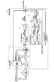
- FIG. FIG. 1 is a diagram showing a configuration of a speed estimation device for an AC motor according to Embodiment 1 of the present invention.
- the speed estimation device for an AC motor according to Embodiment 1 may be simply referred to as a speed estimation device 101.
- the speed estimation apparatus 101 estimates the rotational speed of the AC motor 2 using the voltage and current vectors applied to the AC motor 2 by an adaptive observer method, and outputs the estimated angular speed ⁇ ⁇ r .
- the speed estimation device 101 includes a model deviation calculation unit 11 that calculates a model deviation ⁇ based on the voltage vector, current vector, and estimated angular velocity ⁇ ⁇ r , and a first low-frequency component that includes a DC component of the actual angular velocity based on the model deviation ⁇ . And the first angular velocity estimation unit 21 that calculates the estimated angular velocity ⁇ ⁇ r1 . Further, the speed estimation apparatus 101 includes a second angular velocity estimation unit 22 that calculates a second estimated angular velocity ⁇ ⁇ r2 as a high-frequency component of the actual angular velocity based on a specific high-frequency component of the model deviation ⁇ , and a first estimated angular velocity ⁇ ⁇ .
- the speed estimation device 101 is characterized in that it includes a second angular velocity estimation unit 22, and details of the second angular velocity estimation unit 22 will be described later.
- the model deviation computing unit 11 computes and outputs an estimated magnetic flux vector and an estimated current vector based on the voltage vector, current vector, and estimated angular velocity ⁇ ⁇ r of the AC motor 2, and a current vector from the estimated current vector. And a subtractor 13 that calculates and outputs a current deviation vector, a deviation calculator 14 that receives the current deviation vector as an input, extracts an orthogonal component of the estimated magnetic flux vector as a scalar quantity, and outputs this value as a model deviation; Is provided.
- the current estimator 12 estimates current and magnetic flux from the state equation of the AC motor 2.
- the AC motor 2 is a general embedded magnet type synchronous AC motor.
- the current estimator 12 has an equation of state. If possible, the current can be estimated by the same method.
- Examples of the AC motor 2 other than the embedded magnet type synchronous AC motor include a surface magnet type synchronous motor and an induction motor.
- this application demonstrates about a rotary motor, the same technique is applicable also to a direct acting motor. The reason is that a “linear motion motor can be interpreted as a rotary motor having an infinite rotor radius”.
- L d and L q represent inductances of the d axis and the q axis.
- R represents an armature resistance.
- ⁇ represents the primary angular frequency.
- ⁇ r represents the angular velocity.
- v ds represents the d-axis voltage.
- v qs represents the q-axis voltage.
- i ds represents the d-axis current.
- i qs represents a q-axis current.
- ⁇ ds represents the d-axis stator magnetic flux.
- ⁇ qs represents the q-axis stator magnetic flux.
- ⁇ dr represents the d-axis rotor magnetic flux.
- the symbol “ ⁇ ” represents an estimated value.
- the primary angular frequency is given by the following equation (3). From h 41 h 42 represents a observer gain.
- the above formula (1) and the above formula (2) are formulas based on the usual induced voltage. However, the above formula (1) and the above formula (2) may be modified and expressed in the form of an extended induced voltage. Can be calculated. Since the above-mentioned (1) include the estimated angular velocity omega ⁇ r, when the actual angular velocity omega r and the estimated angular velocity omega ⁇ r do not match, an error occurs in current estimation.
- the model deviation ⁇ is defined as in the following equation (4), and the speed estimation apparatus 101 estimates using the first angular velocity estimation unit 21 and the second angular velocity estimation unit 22 so that the model deviation ⁇ becomes zero. Adjust the value of angular velocity ⁇ ⁇ r .
- the difference between the speed estimation apparatus 101 according to the first embodiment and the conventional adaptive observer is that the speed estimation apparatus 101 has a second angular velocity estimation unit 22.
- a conventional adaptive observer will be described.
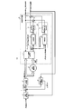
- FIG. 2 is a diagram showing the configuration of an AC motor speed estimation device according to a comparative example.
- FIG. 2 shows a speed estimation apparatus 101A that operates according to a sensorless vector control method using a conventional adaptive observer.
- An adaptive observer of the speed estimation apparatus 101A is disclosed in Japanese Patent Application Laid-Open No. 2003-302413.
- the speed estimation apparatus 101A only the first angular speed estimation unit 21 tries to adjust the model deviation ⁇ to zero.
- the first angular speed estimation unit 21 is configured by a PI (Proportional Integral) controller and an integrator (not shown).
- the speed estimation apparatus 101A adjusts the estimated angular speed ⁇ ⁇ r according to the following equation (5).
- K P represents the proportional gain of the first angular velocity estimation unit 21.
- K I represents the integral gain of the first angular velocity estimator 21.
- s is an operator of Laplace transform, s represents differentiation, and 1 / s represents integration.
- the configuration of the first angular velocity estimation unit 21 included in the velocity estimation device 101A is an example, and another controller may be used. For example, according to Japanese Patent Laid-Open No. 2003-302413, a case is known in which the first angular velocity estimation unit 21 is configured only by PI control without using an integrator.
- the transfer function Ga (s) from the estimated angular velocity ⁇ ⁇ r to the model deviation ⁇ is a non-patent document of the IEEJ Transaction “Speed Sensorless Vector Control Method for Induction Motors Including Low-Speed / Regenerative Regions” (D120, Vol. 2) (2000), which is known on page 226, and can be approximated by a first-order lag as shown in the following equation (6).
- FIG. 3 is a Bode diagram of the speed estimation device shown in FIG.
- the horizontal axis represents frequency
- the vertical axis represents gain.
- the transfer function of the first angular velocity estimator 21 (1) indicated by the dotted line in FIG. 3 is designed so that the low-frequency gain is high.
- the gain decreases as the frequency increases.
- the gain decreases at a rate of ⁇ 40 dB / decade at a low frequency, and decreases at a rate of ⁇ 20 dB / decade at a frequency higher than the break point.
- the transfer function Ga (s) in (2) indicated by a dotted line in FIG. 3 corresponds to the transfer function Ga (s) in the above equation (6), and has a first-order lag characteristic from the estimated angular velocity ⁇ ⁇ r to the model deviation ⁇ . Therefore, the gain decreases at a rate of ⁇ 20 dB / decade in a frequency range higher than the cutoff angular frequency.
- Equation (5) of the PI control gain i.e., if it is possible to sufficiently large and proportional gain K P of the first angular velocity estimator 21 and the integral gain K I of the first angular velocity estimator 21, a high frequency rate of Accurate estimation of pulsation.
- the gain is limited by the influence of the error in the estimation calculation cycle and the motor constant. If the gain is increased forcibly, it will be easily affected by high frequency noise and cannot be estimated properly. For this reason, it is difficult for the speed estimation apparatus 101A of the comparative example to capture high-frequency speed pulsations.
- FIG. 4 is a Bode diagram of the speed estimation device for an AC motor according to Embodiment 1 of the present invention.
- the transfer functions of (1) and (2) in FIG. 4 are the same as the transfer functions of (1) and (2) in FIG.
- the transfer function (3) indicated by the alternate long and short dash line is a characteristic of the transfer function of the second angular velocity estimation unit 22 shown in FIG.
- the characteristic (4) indicated by the solid line is an open loop characteristic obtained by adding the transfer functions (1) to (3).
- the second angular velocity estimation unit 22 shown in FIG. 1 is a controller having a peak at a specific frequency so as to capture high-frequency velocity pulsations.
- the speed estimation device 101 changes the open loop characteristics by using the first angular velocity estimation unit 21 and the second angular velocity estimation unit 22 together.
- the second angular velocity estimation unit 22 does not increase the gain in all high frequency ranges, but increases the gain only in a specific frequency band in which the occurrence of velocity pulsation can be expected due to periodic disturbance. Thereby,
- FIG. 5 is a hardware configuration diagram of the speed estimation device for an AC motor according to Embodiment 1 of the present invention.
- the voltage vector corresponds to a voltage command generated by the power converter that is the voltage application unit 3 shown in FIG. 5 and input to the speed estimation device 101.
- the current vector is generated by the current detector 4 shown in FIG.
- the current detection unit 4 detects an alternating current output from the driving device (not shown) toward the alternating current electric motor 2 and converts the detected alternating current into a dq axis current detection value on the dq coordinate axis.
- the speed estimation apparatus 101 includes a processor 901 and a memory 902.
- the memory 902 includes a volatile storage device (not shown) typified by a random access memory and a nonvolatile auxiliary storage device (not shown) typified by a flash memory. Note that the memory 902 may include a hard disk auxiliary storage device instead of the volatile storage device and the nonvolatile auxiliary storage device.
- the processor 901 executes a program input from the memory 902. Since the memory 902 includes an auxiliary storage device and a volatile storage device, a program is input to the processor 901 from the auxiliary storage device via the volatile storage device.
- the processor 901 may output the calculation result data to the volatile storage device of the memory 902, or may store the data in the auxiliary storage device via the volatile storage device.
- the voltage application unit 3 and the current detection unit 4 may be provided inside the speed estimation device 101. Further, the speed estimation apparatus 101 may include a voltage detection unit that detects a voltage vector output from the voltage application unit 3. In this case, the voltage applying unit may be configured to transmit a command value of the voltage vector to the processor 901 and to transmit a numerical value related to the voltage detected by the voltage detecting unit to the processor 901. The current detection unit 4 may also be configured to transmit the detected numerical value to the processor 901 in the same manner.
- the processor 901 calculates the estimated angular velocity ⁇ ⁇ r based on the current vector and the voltage vector of the AC motor 2.
- the processor 901 may also serve as a driving device for the AC motor 2. That is, the processor 901 may be configured not only to perform speed estimation, but also to calculate a voltage command vector such that the estimated speed becomes a desired value.
- Various methods are known for performing torque control without a position sensor, including the above-mentioned non-patent literature.
- FIG. 6A is a diagram illustrating a detailed configuration of the first angular velocity estimation unit and the second angular velocity estimation unit illustrated in FIG. 1.
- the first angular velocity estimation unit 21 integrates the PI controller 24 that calculates the first estimated angular acceleration based on the model deviation ⁇ , and the first estimated angular acceleration.
- an integrator 25 that outputs a first estimated angular velocity ⁇ ⁇ r1 . Since the dimension of the output of the integrator 25 is speed, the PI controller 24 is referred to as a first angular acceleration estimation unit.
- the first estimated angular acceleration is estimated as a low frequency component including a direct current component of the actual angular velocity.
- the second angular velocity estimation unit 22 which is a second angular acceleration estimation unit includes a second angular acceleration estimation unit 30 which calculates a second estimated angular acceleration based on the frequency fd of the periodic disturbance and the model deviation ⁇ . And an integrator 31 that integrates the second estimated angular acceleration and outputs a second estimated angular velocity ⁇ ⁇ r2 .
- the second angular acceleration estimator 30 includes a Fourier coefficient calculator 26 that extracts a specific high-frequency component of the model deviation ⁇ by converting it into a direct current, and an angular acceleration estimation error based on the high-frequency component extracted by the Fourier coefficient calculator 26.
- PI controller 27 and PI controller 28 which are angular velocity auxiliary calculators for correcting the above, and AC restorer 29 for restoring the outputs of PI controller 27 and PI controller 28 to AC.
- the Fourier coefficient calculator 26 is used as the frequency analyzer, but another type of frequency analysis method such as a wavelet transform may be used.
- the Fourier coefficient calculator 26 extracts a specific high frequency component of the model deviation ⁇ . If at a frequency of the periodic disturbance and f d, cosine coefficient E c and sine coefficients E s model deviation ⁇ is calculated by the following equation (7) and the following equation (8). t represents time.
- the PI controller 27 PI-controls the cosine coefficient E c of the model deviation ⁇ as shown in the following equation (9).
- PI controller 28 to a sine factor E s model deviation ⁇ to the PI control as described below (10).
- AC decompressor 29 by performing the following operation (11) using a sine coefficient E s which is PI controlled by the PI controlled cosine coefficients E c and the PI controller 28 in the PI controller 27, the actual The second angular acceleration can be estimated as a specific high frequency component of the angular acceleration.
- K P2 represents a proportional gain of the second angular velocity estimator 22
- K I2 represents an integral gain of the second angular velocity estimator 22
- the integrator 31 integrates the second angular acceleration estimated by the AC restorer 29 by the following equation (12) to obtain the second estimated angular velocity ⁇ ⁇ r2 .
- the second estimated angular velocity ⁇ ⁇ r2 is calculated as a specific high-frequency component of the actual angular velocity.
- the angular velocity estimation formula is finally expressed by the following formula (13). That is, the adder 23 adds the second estimated angular velocity ⁇ ⁇ r2 calculated by the integrator 31 to the first estimated angular velocity ⁇ ⁇ r1 calculated by the first angular velocity estimator 21 to obtain the following ( 13) The estimated angular velocity ⁇ ⁇ r in the equation (13) is obtained.
- the difference between the expression (13) and the expression (5) is that the second estimated angular velocity ⁇ ⁇ r2 is used in the expression (13).
- the second angular velocity estimation unit 22 extracts the arbitrary harmonic of the model deviation ⁇ into a sine wave and a cosine wave and converts it into a direct current, performs PI control so that it becomes zero, and restores the output of the PI control to an alternating current. Then, by integrating it, the high frequency component of the actual angular velocity is estimated, thereby increasing the gain only for a specific frequency portion. Therefore, the pulsation component of the speed caused by the periodic disturbance can be estimated with high accuracy as the second estimated angular speed ⁇ ⁇ r2 .
- the second angular velocity estimation unit 22 described above has a structure of a kind of repetitive controller or learning controller. Therefore, another type of iterative controller or learning controller may be used instead of the second angular velocity estimation unit 22 described above. Further, as described in detail in the second embodiment, the integrator 31 of FIG. 6A may be omitted, and the output of the AC restorer 29 may be handled as the second estimated angular velocity.
- FIG. 7A is a diagram showing a simulation result by the speed estimation device for the conventional AC motor shown in FIG. 2
- FIG. 7B is a diagram showing a simulation result by the speed estimation device for the AC motor according to Embodiment 1 of the present invention.
- the vertical axis represents angular velocity
- the horizontal axis represents time.
- the speed estimation device 101A if the frequency of the velocity pulsation by periodic disturbance occurs, it delays the phase of the estimated angular velocity omega ⁇ r indicated by the solid line to the actual angular velocity omega r indicated by the dotted line as shown in Figure 7A. An amplitude error also occurs between the actual angular velocity ⁇ r and the estimated angular velocity ⁇ ⁇ r . Thus, the speed estimation accuracy is low in the conventional speed estimation apparatus 101A.
- the speed estimation apparatus 101 is adversely affected by the speed control due to the phase delay of the estimated angular velocities ⁇ ⁇ r .
- the speed estimation apparatus 101 according to the first embodiment can not only estimate the speed with high accuracy, but also helps improve the control performance when it is used for control.
- another feature of the angular velocity estimation method in the velocity estimation apparatus 101 according to the first embodiment is that the angular acceleration is estimated without performing a differential operation.
- a differential operation is usually required, but noise tends to occur in the differential operation.
- a low-pass filter is used to avoid the influence of differential noise, but the accuracy of estimation of angular acceleration in a high frequency region is degraded by the low-pass filter. Since the speed estimation apparatus 101 according to the first embodiment obtains angular acceleration without performing differentiation, the speed estimation apparatus 101 according to the first embodiment can obtain a waveform having a small noise effect, and will be described later. It becomes easier to perform pulsation suppression control.
- FIG. FIG. 6B is a diagram showing the configuration of the speed estimation device for an AC motor according to Embodiment 2 of the present invention.
- the difference between the first and second embodiments is that, in the speed estimation device 101 according to the second embodiment, the integrator 25 and the integrator 31 are omitted from the configuration of the speed estimation device 101 according to the first embodiment. It is.
- the first angular velocity estimation unit 21A is used instead of the first angular velocity estimation unit 21, and the second angular velocity estimation unit 22 is replaced with the second angular velocity estimation unit 22.
- the angular velocity estimating unit 22A is used, the integrator 25 is omitted in the first angular velocity estimating unit 21A, and the integrator 31 is omitted in the second angular velocity estimating unit 22A.
- the PI controller 27 performs PI control of the cosine coefficient E c of the model deviation ⁇ as shown in the following equation (14).
- K P3 represents the proportional gain of the second angular velocity estimator 22A
- K I3 represents an integral gain of the second angular velocity estimator 22A.
- PI controller 28 to a sine factor E s model deviation ⁇ to the PI control as described below (15).
- the second angular velocity can be estimated as a specific high-frequency component of the angular velocity.
- the angular velocity estimation formula is finally expressed by the following formula (17).
- K P4 represents the proportional gain of the first angular velocity estimator 21A
- K I4 represents the integral gain of the first angular velocity estimator 21A. That is, the adder 23 adds the second estimated angular velocity ⁇ ⁇ r3 calculated by the AC restorer 29 to the first estimated angular velocity ⁇ ⁇ r1A calculated by the first angular velocity estimator 21A.
- the estimated angular velocity ⁇ ⁇ r in the equation (17) is obtained.
- the first angular velocity estimation unit 21 is configured only by PI control without using the integrator 25.
- the second angular velocity estimation unit 22 can be configured without using the integrator 31.
- the speed estimation apparatus 101 shown in FIG. 6B is configured, high-frequency speed pulsations can be accurately estimated as compared with the conventional example that does not have the integrator 25, similarly to the speed estimation apparatus 101 according to the first embodiment. The reason for this overlaps with the contents described in the first embodiment, and therefore the description is omitted.
- the first angular velocity estimation unit 21 includes the integrator 25 and the second angular velocity estimation unit 22 does not include the integrator 31, or the first angular velocity estimation unit 21 performs integration.
- a configuration is also conceivable in which the second angular velocity estimation unit 22 is not provided with the integrator 25 and the integrator 31 is provided.
- the second embodiment is inferior to the first embodiment, but the second embodiment is more advantageous because the integral calculation is omitted in terms of the amount of calculation required for the estimation calculation.
- the configuration of the second embodiment is suitable when the calculation performance of the processor 901 shown in FIG.
- the configuration of the speed estimation apparatus 101 according to the first embodiment is suitable when the speed pulsation suppression control described in the sixth embodiment is performed.
- FIG. FIG. 8 is a diagram showing the configuration of the speed estimation device for an AC motor according to Embodiment 3 of the present invention.
- the difference between the first and third embodiments is that the speed estimation apparatus 101 according to the second embodiment includes a suppression frequency determination unit 32 in addition to the configuration of the speed estimation apparatus 101 according to the first embodiment.
- the vibration of the 1f component of the mechanical angular velocity is very large.
- the vibration of the 2f component of the mechanical angular velocity is large.
- the vibration peak is dispersed due to its structure, but the vibration at the electrical angles 1f, 2f, and 3f is relatively large.
- the distortion of the induced voltage of the AC motor 2 or the output voltage error due to the upper and lower short-circuit prevention time of the power converter causes the vibration of the electrical angular frequency 6f.
- the offset and gain imbalance of the current detector cause vibration of the electrical angle 1f and vibration of the electrical angle 2f, respectively.
- the frequency f d of the periodic disturbance can often be expressed as a function of the angular velocity of the AC motor 2.
- the speed estimation apparatus 101 includes a suppression frequency determination unit 32 on the assumption that the frequency f d of the periodic disturbance changes in synchronization with the angular speed of the AC motor 2.
- the suppression frequency determination unit 32 calculates the frequency f d of the periodic disturbance from the estimated angular velocity ⁇ ⁇ r output from the adder 23. Since the frequency f d of the periodic disturbance can often be expressed as a function of the angular velocity of the AC motor 2, the ratio f d / ⁇ r between the frequency f d of the periodic disturbance and the angular velocity ⁇ r of the AC motor 2 is set here as ⁇ . ⁇ takes a different value depending on the cause of the periodic disturbance.
- the suppression frequency determination unit 32 determines the frequency f d of the periodic disturbance, that is, the suppression frequency, by multiplying the estimated angular velocity ⁇ ⁇ r by the ratio ⁇ determined by the generation factor of the periodic disturbance.
- the designer of the speed estimation device 101 may arbitrarily determine which periodic disturbance element is suppressed among various periodic disturbances applied to the AC motor 2. Normally, it is designed to suppress periodic disturbance factors that have a large effect on speed estimation.
- the frequency f d of the periodic disturbance calculated by the suppression frequency determination unit 32 is used for the calculation by the Fourier coefficient calculator 26. Thereby, even when the speed of the AC motor 2 changes, accurate speed estimation can be performed.
- FIG. FIG. 9 is a diagram showing the configuration of the speed estimation device for an AC motor according to Embodiment 4 of the present invention.
- the speed estimation apparatus 101 according to the fourth embodiment includes the second period in addition to the second angular speed estimation unit 22 that calculates the second estimated angular speed as the first high-frequency component of the actual angular speed caused by the first periodic disturbance.
- a third angular velocity estimation unit 33 that calculates a third estimated angular velocity as a second high-frequency component of the actual angular velocity caused by the disturbance is provided.
- the configuration of the third angular velocity estimator 33 is the same as that of the second angular velocity estimator 22, but the second angular velocity estimator 22 is input with the frequency of the first periodic disturbance.
- the third angular velocity estimation unit 33 is different in that the frequency of the second periodic disturbance is input. Note that when the processing capacity of the processor 901 shown in FIG. 5 has a margin, the speed estimation apparatus 101 may have more angular speed estimation units in parallel.
- an nth angular velocity estimation unit 34 that reduces a velocity estimation error due to the (n ⁇ 1) th periodic disturbance is provided. However, n is a positive integer of 3 or more.
- FIG. FIG. 10 is a diagram showing the configuration of an AC motor drive device according to Embodiment 5 of the present invention.
- the AC electric motor drive device according to Embodiment 5 may be simply referred to as drive device 102.
- the drive device 102 includes a speed estimation device 101 according to the first, second, or third embodiment, a speed control unit 5, a torque control unit 6 that is a voltage application unit, an adder 7, and a cycle. And a compensation torque calculation unit 8 that generates a compensation torque signal that reduces the speed pulsation caused by the disturbance.
- a PID controller is used for the speed control unit 5, and the speed control unit 5 generates a torque command by performing proportional, integral and differential operations based on the speed deviation so that the speed deviation becomes zero. To do.
- a torque command may be generated by feedforward from the angular velocity command, and a PID controller and a feedforward controller may be used in combination.
- the torque control unit 6 includes a voltage application unit 3 shown in FIG.
- the speed estimation device 101 includes the adder 35 that calculates the estimated angular acceleration by adding the second estimated angular acceleration to the first estimated angular acceleration.
- the compensation torque calculation unit 8 includes a disturbance torque estimation unit (not shown) that estimates disturbance torque based on the estimated angular acceleration calculated by the speed estimation device 101, and compensates based on the disturbance torque estimated by the disturbance torque estimation unit. Generate a torque signal.
- the driving device 102 includes a current detection unit (not shown) that detects a current flowing through the AC motor 2.
- the current detection unit corresponds to the current detection unit 4 shown in FIG.
- the driving device 102 performs pulsation compensation by the compensation torque calculation unit 8.
- the torque control unit 6 can control the torque according to the command value
- the angular velocity ⁇ r of the AC motor 2 is expressed by the following equation (18).
- J represents inertia
- ⁇ * represents a torque command
- ⁇ L is a load torque
- s is an operator of Laplace transform.
- the (19) equation is an equation of the load torque tau L. If the inertia is known, the load torque ⁇ L can be calculated from the estimated angular acceleration and the torque command ⁇ * .
- a disturbance torque estimation unit (not shown) in the compensation torque calculation unit 8 estimates the load torque ⁇ L based on the load torque ⁇ L and the estimated angular acceleration calculated by the adder 35.
- the generated torque for measuring the generated torque A measuring means may be further provided.
- the compensation torque calculator 8 determines a compensation torque for compensating for the speed pulsation based on the estimated load torque. If it is desired to make the speed pulsation zero, the load torque ⁇ L and the torque command ⁇ * may be made to coincide with each other. Therefore, the load torque ⁇ L estimated by the above equation (19) is used as the compensation torque to the torque command ⁇ * . Add it. Normally, in order to reduce the sensitivity to noise, a low-pass filter is applied to the estimated load torque to ensure the stability of the control system. In addition, when it is desired to cancel only a specific high-frequency periodic disturbance component in the estimated load torque ⁇ L , a band pass filter may be used. Even if only a specific high-frequency component is extracted by Fourier series expansion and restored to alternating current, the same effect as that of the band-pass filter can be obtained.
- Such a compensation torque calculation method is a very common method in the control using the position sensor, but cannot be used in the conventional position sensorless control. This is because the conventional position sensorless control cannot capture high-speed velocity pulsations with high accuracy.
- the drive device 102 according to the fifth embodiment can capture high-frequency velocity pulsations with high accuracy by using the velocity estimation device 101 according to the first embodiment, the third embodiment, or the fourth embodiment. Therefore, the compensation torque calculation method described above can be used even in position sensorless control, and speed pulsation can be reduced.
- the periodic disturbance is the load torque pulsation of the mechanical load device connected to the AC motor 2, and the compensation torque calculation unit 8 according to the fifth embodiment suppresses the speed pulsation caused by the load torque pulsation. To do.
- the periodic disturbance is caused by the torque ripple caused by the short circuit prevention time of the voltage application unit, the torque ripple caused by the distortion of the induced voltage of the AC motor 2, and the offset error of the current detection unit 4.
- the torque ripple is either a torque ripple or a torque ripple caused by a current detection gain error of the current detection unit 4, and the compensation torque calculation unit 8 suppresses speed pulsation caused by the torque ripple. This makes it possible to suppress high-frequency velocity pulsation without prior adjustment.
- FIG. FIG. 11 is a diagram showing the configuration of an AC motor drive device according to Embodiment 6 of the present invention.
- the difference between the fifth embodiment and the sixth embodiment is that the drive device 102 according to the sixth embodiment suppresses the speed pulsation in place of the compensation torque calculator 8 of the drive device 102 according to the fifth embodiment.
- the operating speed pulsation suppressing unit 9 is used.
- the speed pulsation suppressing unit 9 generates a compensation torque ⁇ * rip that is a compensation torque signal that reduces the speed pulsation caused by the periodic disturbance based on the estimated angular speed ⁇ ⁇ r calculated by the speed estimation device 101.
- the speed pulsation suppressing unit 9 includes a speed pulsation calculator 91, a PI controller 92, a PI controller 93, and an AC restorer 94.
- compensation for velocity pulsation using angular acceleration amplitude will be described.
- the velocity pulsation calculator 91 calculates the velocity pulsation amplitude.
- the estimated speed may be expanded as it is in the Fourier series, the calculation is performed according to the following procedure for the reason described later.
- the velocity pulsation ⁇ rip is given by the following equation (20).
- cosine coefficient ⁇ which is a cosine component of velocity pulsation It can be seen that c is obtained from the following equation (22), and the cosine coefficient ⁇ ⁇ s, which is a sine component, is obtained from the following equation (23).
- K P3 represents the proportional gain of the speed pulsation suppressing portion 9
- K I3 represents an integral gain of the speed pulsation suppression portion 9.
- control is performed by expanding the velocity in the Fourier series.
- the speed pulsation is calculated by a simple calculation formula shown in the above formula (22) and the above formula (23).
- the driving device 102 determines the compensation torque ⁇ * rip in consideration of the phase difference as in the above equation (26), thereby ensuring the phase margin and stabilizing the speed pulsation suppression control. Is configured to do.
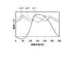
- FIG. 12A is a diagram showing a simulation result by the speed control method disclosed in Patent Document 1
- FIG. 12B is a diagram showing a simulation result by the AC motor driving device according to Embodiment 6 of the present invention.
- the vertical axis represents the velocity deviation amplitude
- the horizontal axis represents the frequency.
- 12A and 12B compare the FFT results of the speed pulsation when the refrigerant compressor that generates the load torque pulsation of the mechanical angle 1f is rotated at a high speed. When the control system was designed so that the speed pulsation at the mechanical angle 1f disappeared, the speed pulsation at the mechanical angle 1f was reduced by the control of the fifth embodiment.
- the present invention is also effective for periodic disturbances of other frequencies. Further, if it is desired to simultaneously suppress the influence of a plurality of periodic disturbances, the speed pulsation suppressing unit 9 may be parallelized.
- the first angular velocity estimation unit 21 and the second angular acceleration estimation unit 30 are provided, so that high-frequency velocity pulsation can be accurately performed.
- this speed pulsation can be compensated without prior adjustment.
- FIG. FIG. 13 is a diagram showing a configuration of a refrigerant compressor according to Embodiment 7 of the present invention.
- a refrigerant compressor 200 according to Embodiment 7 includes a drive device 102 and a compression mechanism 2a according to Embodiment 6.
- a compression mechanism 2 a shown in FIG. 13 includes an AC motor 2, a shaft 201, and a compression unit 202.
- the refrigerant compressor 200 according to the seventh embodiment includes the second angular velocity estimating unit 22 and the velocity pulsation suppressing unit 9 according to the sixth embodiment in order to reduce the speed pulsation of the AC motor 2.
- FIG. 14 is a cross-sectional view of the compression mechanism shown in FIG.
- the rolling piston type compression mechanism 2a will be described, but the compression mechanism 2a used in the refrigerant compressor 200 according to Embodiment 7 is not limited to the rolling piston type, and may be a scroll type compressor.
- the compression mechanism 2 a includes a sealed container 211, an AC motor 2 built in the sealed container 211, a shaft 201 having one end penetrating the rotor 2-1 constituting the AC motor 2, and the other end of the shaft 201 penetrating.
- a compression unit 202 fixed inside the container 211, a suction pipe 203 provided in the sealed container 211, and a discharge pipe 204 provided in the sealed container 211 are provided.
- the stator 2-2 of the AC motor 2 is attached and held in the sealed container 211 by shrink fitting, cold fitting, or welding. Electric power is supplied to the coil 2-3 of the stator 2-2 through an electric wire (not shown).
- the rotor 2-1 is disposed inside the stator 2-2 via a gap 2-4, and is rotatably held by a bearing (not shown) via a shaft 201 at the center of the rotor 2-1. Yes.
- the compression mechanism 2 a configured as described above, when the AC motor 2 is driven, the refrigerant sucked into the compression unit 202 via the suction pipe 203 is compressed, and the compressed refrigerant is discharged from the discharge pipe 204.
- the compression mechanism 2a often has a structure in which the AC motor 2 is immersed in the refrigerant, and since the temperature change is severe, it is difficult to attach a position sensor to the AC motor 2. Therefore, in the refrigerant compressor 200, the AC motor 2 must be driven without a position sensor.
- FIG. 15 is a diagram showing the configuration of the compression unit shown in FIG.
- the compression unit 202 includes an annular cylinder 212, a piston 205 that is integrally rotatable with the shaft 201 and disposed inside the cylinder 212, and a compression chamber 213 provided on the inner peripheral portion of the cylinder 212. .
- the cylinder 212 includes a suction port 206 that communicates with the suction pipe 203 shown in FIG. 14 and a discharge port 207 that discharges the compressed refrigerant.
- the suction port 206 and the discharge port 207 are in communication with the compression chamber 213.
- the cylinder 212 includes a vane 210 that divides the compression chamber 213 into a low-pressure chamber that communicates with the suction pipe 203 and a high-pressure chamber that communicates with the discharge port 207, and a spring 209 that biases the vane 210.
- the shaft 201 connects the AC motor 2 and the piston 205 to each other.
- the piston 205 is eccentric, and the volumes on the discharge side and the suction side change depending on the rotation angle.
- the refrigerant sucked from the suction port 206 is compressed by the piston 205, and when the pressure in the compression chamber 213 increases, the discharge valve 208 opens and the refrigerant is discharged from the discharge port 207. At the same time as the refrigerant is discharged, the refrigerant flows into the suction side.
- the AC motor 2 is continuously rotated, the refrigerant is discharged once per rotation of the piston 205 at a mechanical angle.
- FIG. 16 is a diagram showing a waveform of load torque in the rolling piston type compression mechanism shown in FIG.
- the vertical axis in FIG. 16 represents the load torque
- the horizontal axis represents the rotation angle that is the mechanical angle of the piston 205.
- FIG. 16 shows the variation of the load torque with respect to the mechanical angle of the piston 205.
- one compression chamber 213 is shown in FIG. 15, a plurality of compression chambers 213 may be provided in the cylinder 212.
- the number of compression chambers 213 is set to k.
- k 1, that is, when there is one compression chamber 213, the load torque vibrates greatly with a mechanical angular period.
- the secondary and tertiary harmonics are also included in the load torque waveform, but the primary vibration is the largest.
- the load torque pulsation can be reduced by shifting the angle of the piston 205.
- the number of the compression chambers 213 is increased, a waveform with small pulsation can be obtained, but the structure becomes complicated and the cost increases.
- the cycle of the load torque pulsation becomes shorter in inverse proportion to the number of compression chambers 213.
- the load torque pulsation of the compression mechanism 2a is a periodic disturbance to the AC motor 2, it causes a speed pulsation.
- the compression mechanism 2a it is generally known that noise and vibration increase when the speed pulsation is large.
- the refrigerant compressor 200 uses this fact to construct the control system shown in FIG.
- the refrigerant compressor 200 estimates the specific frequency component of the speed pulsation with high accuracy by the second angular velocity estimation unit 22, and calculates a compensation torque ⁇ * rip that suppresses the pulsation by the speed pulsation suppression unit 9.
- speed pulsation can be reduced without prior adjustment. Since pre-adjustment is not necessary, the adjustment cost before shipment can be greatly reduced, which is very useful.
- the configuration example of the refrigerant compressor 200 using the driving device 102 and the compression mechanism 2a according to the sixth embodiment has been described.
- the refrigerant compressor 200 according to the seventh embodiment is replaced with these.
- the second angular velocity estimation unit 22 and the compensation torque calculation unit 8 according to the fifth embodiment may be used, and similar effects can be obtained even when configured in this way.
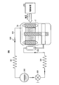
- FIG. 17 is a diagram showing a configuration of a refrigeration cycle apparatus according to Embodiment 8 of the present invention.
- a refrigeration cycle apparatus 300 shown in FIG. 17 includes an AC motor drive device 102, a compression mechanism 2a, a condenser 301 connected to the compression mechanism 2a via a pipe 305, and a condenser 301 via a pipe 305.
- a liquid receiver 302 to be connected, an expansion valve 303 connected to the liquid receiver 302 via a pipe 305, and an evaporator 304 connected to the expansion valve 303 via a pipe 305 are provided.
- the evaporator 304 is connected to the suction pipe 203.
- the compression mechanism 2 a, the condenser 301, the liquid receiver 302, the expansion valve 303, the evaporator 304, and the suction pipe 203 are connected by a pipe 305, whereby the compression mechanism 2 a, the condenser 301, the liquid receiver 302, and the expansion valve 303 are connected.
- the evaporator 304 and the suction pipe 203 constitute a refrigeration cycle circuit 306 in which the refrigerant circulates. In the refrigeration cycle circuit 306, steps of evaporation, compression, condensation, and expansion of the refrigerant are repeated, and heat is transferred while the refrigerant repeatedly changes from liquid to gas or from gas to liquid.
- the evaporator 304 evaporates the refrigerant liquid in a low pressure state, takes heat from the surroundings, and has a cooling action.
- the compression mechanism 2a compresses the refrigerant gas into a high-pressure gas in order to condense the refrigerant.
- the compression mechanism 2a is driven by the drive device 102 according to the fourth and fifth embodiments.
- the condenser 301 releases heat to condense the high-pressure refrigerant gas into a refrigerant liquid.
- the expansion valve 303 squeezes and expands the refrigerant liquid to evaporate the refrigerant to make it a low-pressure liquid.
- the liquid receiver 302 is provided for adjusting the amount of circulating refrigerant, and may be omitted in a small apparatus.
- the single rotary compressor is the rotary compressor described with reference to FIGS. 14 and 15, and is a type of compressor having only one compression chamber 213.
- a rotary compressor has a very large load torque pulsation, and thus tends to have a large vibration and noise.
- the conventional feedforward control method requires complicated control adjustment in order to suppress vibration and noise.
- the refrigeration cycle apparatus 300 Since the refrigeration cycle apparatus 300 according to the eighth embodiment performs feedback control so that the driving apparatus 102 automatically sets the speed pulsation to zero, the cost required for adjustment before shipment can be significantly reduced. Further, according to the eighth embodiment, by suppressing the speed pulsation by feedback control, it becomes possible to flexibly cope with variations during manufacturing, motor constant fluctuations, and changes in compressor load conditions. A highly refrigerating cycle apparatus 300 can be realized.
- the configuration described in the above embodiment shows an example of the contents of the present invention, and can be combined with another known technique, and can be combined with other configurations without departing from the gist of the present invention. It is also possible to omit or change the part.
Landscapes
- Engineering & Computer Science (AREA)
- Power Engineering (AREA)
- Physics & Mathematics (AREA)
- General Physics & Mathematics (AREA)
- Automation & Control Theory (AREA)
- Mechanical Engineering (AREA)
- Thermal Sciences (AREA)
- General Engineering & Computer Science (AREA)
- Control Of Ac Motors In General (AREA)
- Control Of Electric Motors In General (AREA)
- Control Of Positive-Displacement Pumps (AREA)
Abstract
Priority Applications (5)
| Application Number | Priority Date | Filing Date | Title |
|---|---|---|---|
| JP2018522360A JP6537725B2 (ja) | 2016-06-08 | 2017-04-18 | 交流電動機の速度推定装置、交流電動機の駆動装置、冷媒圧縮機および冷凍サイクル装置 |
| GB1816623.1A GB2566166B (en) | 2016-06-08 | 2017-04-18 | Speed estimation apparatus for AC motor, driving apparatus for AC motor, refrigerant compressor, and refrigeration cycle apparatus |
| DE112017002279.7T DE112017002279B4 (de) | 2016-06-08 | 2017-04-18 | Drehzahlschätzungsvorrichtung für ac-motor, antriebsvorrichtung für ac-motor, kältemittelverdichter und kältekreislaufvorrichtung |
| US16/098,313 US11098928B2 (en) | 2016-06-08 | 2017-04-18 | Speed estimation apparatus for AC motor, driving apparatus for AC motor, refrigerant compressor, and refrigeration cycle apparatus |
| CN201780033623.0A CN109219922B (zh) | 2016-06-08 | 2017-04-18 | 交流电动机的速度推测装置、交流电动机的驱动装置、制冷剂压缩机及冷冻循环装置 |
Applications Claiming Priority (2)
| Application Number | Priority Date | Filing Date | Title |
|---|---|---|---|
| JP2016114609 | 2016-06-08 | ||
| JP2016-114609 | 2016-06-08 |
Publications (1)
| Publication Number | Publication Date |
|---|---|
| WO2017212794A1 true WO2017212794A1 (fr) | 2017-12-14 |
Family
ID=60577657
Family Applications (1)
| Application Number | Title | Priority Date | Filing Date |
|---|---|---|---|
| PCT/JP2017/015561 WO2017212794A1 (fr) | 2016-06-08 | 2017-04-18 | Appareil d'estimation de vitesse pour moteur en ca, appareil d'entraînement pour moteur en ca, compresseur de réfrigérant, et appareil de cycle de congélation |
Country Status (6)
| Country | Link |
|---|---|
| US (1) | US11098928B2 (fr) |
| JP (1) | JP6537725B2 (fr) |
| CN (1) | CN109219922B (fr) |
| DE (1) | DE112017002279B4 (fr) |
| GB (1) | GB2566166B (fr) |
| WO (1) | WO2017212794A1 (fr) |
Cited By (6)
| Publication number | Priority date | Publication date | Assignee | Title |
|---|---|---|---|---|
| JP2020010566A (ja) * | 2018-07-11 | 2020-01-16 | 三菱電機株式会社 | モータ制御装置 |
| WO2020194401A1 (fr) * | 2019-03-22 | 2020-10-01 | 三菱電機株式会社 | Appareil d'estimation de vitesse pour moteur à courant alternatif, appareil d'entraînement pour moteur à courant alternatif, compresseur réfrigérant, et appareil de cycle de réfrigération |
| CN111756300A (zh) * | 2020-06-18 | 2020-10-09 | 中车永济电机有限公司 | 基于电流预测的适用于直线感应电机控制的死区补偿方法 |
| WO2021144856A1 (fr) * | 2020-01-14 | 2021-07-22 | 三菱電機株式会社 | Dispositif d'entraînement de moteur ca, dispositif d'entraînement de compresseur et dispositif de cycle de réfrigération |
| WO2022034674A1 (fr) * | 2020-08-13 | 2022-02-17 | 三菱電機株式会社 | Dispositif de commande de moteur électrique et dispositif d'application de cycle de réfrigération |
| WO2023238293A1 (fr) * | 2022-06-08 | 2023-12-14 | 三菱電機株式会社 | Climatiseur |
Families Citing this family (3)
| Publication number | Priority date | Publication date | Assignee | Title |
|---|---|---|---|---|
| DE102019201798A1 (de) * | 2019-02-12 | 2020-08-13 | Festo Se & Co. Kg | Antriebssystem, Trajektorien-Planungseinheit und Verfahren |
| US20230161300A1 (en) * | 2020-01-09 | 2023-05-25 | Lg Innotek Co., Ltd. | Production equipment for performing control parameter setting and quality determination |
| EP3930177A1 (fr) * | 2020-06-22 | 2021-12-29 | Bombardier Transportation GmbH | Procédé de régulation d'une machine à courant triphasée électrique ainsi que système de machine à courant triphasée pour un tel procédé |
Citations (3)
| Publication number | Priority date | Publication date | Assignee | Title |
|---|---|---|---|---|
| JP2003302413A (ja) * | 2002-04-08 | 2003-10-24 | Mitsubishi Electric Corp | 回転機の速度推定装置 |
| JP2010088200A (ja) * | 2008-09-30 | 2010-04-15 | Calsonic Kansei Corp | 電動モータの制御装置 |
| JP2013179753A (ja) * | 2012-02-28 | 2013-09-09 | Calsonic Kansei Corp | 電動モータの制御装置 |
Family Cites Families (10)
| Publication number | Priority date | Publication date | Assignee | Title |
|---|---|---|---|---|
| JPH01308184A (ja) | 1988-06-01 | 1989-12-12 | Hitachi Ltd | 移動体の速度制御方法 |
| JP3612636B2 (ja) * | 1996-09-18 | 2005-01-19 | 有限会社シー・アンド・エス国際研究所 | 同期電動機のベクトル制御方法 |
| JP2001037281A (ja) | 1999-05-18 | 2001-02-09 | Matsushita Electric Ind Co Ltd | 電動機のトルク制御装置 |
| JP4221307B2 (ja) | 2004-01-07 | 2009-02-12 | 日立アプライアンス株式会社 | 同期電動機の制御装置,電気機器およびモジュール |
| JP4685509B2 (ja) * | 2004-07-12 | 2011-05-18 | 株式会社豊田中央研究所 | 交流電動機の駆動制御装置および駆動制御方法 |
| JP4198162B2 (ja) * | 2006-04-07 | 2008-12-17 | 三洋電機株式会社 | モータ制御装置 |
| JP5236965B2 (ja) * | 2008-02-29 | 2013-07-17 | 三菱重工業株式会社 | モータの制御装置 |
| US9048778B2 (en) * | 2010-04-17 | 2015-06-02 | Nidec Corporation | Rotor phase/speed estimating device for an AC motor |
| CN102361430B (zh) * | 2011-10-26 | 2013-03-13 | 哈尔滨工业大学 | 一种内置式永磁同步电机无位置传感器矢量控制装置 |
| CN104218856A (zh) * | 2014-09-11 | 2014-12-17 | 合肥晶弘电器有限公司 | 一种变频冰箱压缩机转子的定位方法和装置 |
-
2017
- 2017-04-18 WO PCT/JP2017/015561 patent/WO2017212794A1/fr active Application Filing
- 2017-04-18 CN CN201780033623.0A patent/CN109219922B/zh active Active
- 2017-04-18 JP JP2018522360A patent/JP6537725B2/ja active Active
- 2017-04-18 DE DE112017002279.7T patent/DE112017002279B4/de active Active
- 2017-04-18 US US16/098,313 patent/US11098928B2/en active Active
- 2017-04-18 GB GB1816623.1A patent/GB2566166B/en active Active
Patent Citations (3)
| Publication number | Priority date | Publication date | Assignee | Title |
|---|---|---|---|---|
| JP2003302413A (ja) * | 2002-04-08 | 2003-10-24 | Mitsubishi Electric Corp | 回転機の速度推定装置 |
| JP2010088200A (ja) * | 2008-09-30 | 2010-04-15 | Calsonic Kansei Corp | 電動モータの制御装置 |
| JP2013179753A (ja) * | 2012-02-28 | 2013-09-09 | Calsonic Kansei Corp | 電動モータの制御装置 |
Cited By (15)
| Publication number | Priority date | Publication date | Assignee | Title |
|---|---|---|---|---|
| JP2020010566A (ja) * | 2018-07-11 | 2020-01-16 | 三菱電機株式会社 | モータ制御装置 |
| JP7012901B2 (ja) | 2019-03-22 | 2022-01-28 | 三菱電機株式会社 | 交流電動機の速度推定装置、交流電動機の駆動装置、冷媒圧縮機及び冷凍サイクル装置 |
| WO2020194401A1 (fr) * | 2019-03-22 | 2020-10-01 | 三菱電機株式会社 | Appareil d'estimation de vitesse pour moteur à courant alternatif, appareil d'entraînement pour moteur à courant alternatif, compresseur réfrigérant, et appareil de cycle de réfrigération |
| US11632067B2 (en) | 2019-03-22 | 2023-04-18 | Mitsubishi Electric Corporation | Speed estimating device for AC motor, driving device for AC motor, refrigerant compressor, and refrigeration cycle apparatus |
| GB2596246B (en) * | 2019-03-22 | 2023-03-08 | Mitsubishi Electric Corp | Speed estimating device for AC motor, driving device for AC motor, refrigerant compressor, and refrigeration cycle apparatus |
| JPWO2020194401A1 (ja) * | 2019-03-22 | 2021-09-13 | 三菱電機株式会社 | 交流電動機の速度推定装置、交流電動機の駆動装置、冷媒圧縮機及び冷凍サイクル装置 |
| GB2596246A (en) * | 2019-03-22 | 2021-12-22 | Mitsubishi Electric Corp | Velocity estimation device of AC motor, driving device of AC motor, refrigerant compressor, and refrigeration cycle device |
| WO2021144856A1 (fr) * | 2020-01-14 | 2021-07-22 | 三菱電機株式会社 | Dispositif d'entraînement de moteur ca, dispositif d'entraînement de compresseur et dispositif de cycle de réfrigération |
| JP7204013B2 (ja) | 2020-01-14 | 2023-01-13 | 三菱電機株式会社 | 交流電動機の駆動装置、圧縮機駆動装置及び冷凍サイクル装置 |
| JPWO2021144856A1 (fr) * | 2020-01-14 | 2021-07-22 | ||
| US11705847B2 (en) | 2020-01-14 | 2023-07-18 | Mitsubishi Electric Corporation | Drive device for AC motor, compressor drive device, and refrigeration cycle device |
| CN111756300A (zh) * | 2020-06-18 | 2020-10-09 | 中车永济电机有限公司 | 基于电流预测的适用于直线感应电机控制的死区补偿方法 |
| WO2022034674A1 (fr) * | 2020-08-13 | 2022-02-17 | 三菱電機株式会社 | Dispositif de commande de moteur électrique et dispositif d'application de cycle de réfrigération |
| JP7361933B2 (ja) | 2020-08-13 | 2023-10-16 | 三菱電機株式会社 | 電動機駆動装置および冷凍サイクル適用機器 |
| WO2023238293A1 (fr) * | 2022-06-08 | 2023-12-14 | 三菱電機株式会社 | Climatiseur |
Also Published As
| Publication number | Publication date |
|---|---|
| DE112017002279T5 (de) | 2019-01-17 |
| US20190145668A1 (en) | 2019-05-16 |
| GB2566166B (en) | 2021-08-04 |
| GB201816623D0 (en) | 2018-11-28 |
| CN109219922B (zh) | 2022-03-15 |
| JP6537725B2 (ja) | 2019-07-03 |
| JPWO2017212794A1 (ja) | 2018-09-06 |
| CN109219922A (zh) | 2019-01-15 |
| DE112017002279B4 (de) | 2023-10-26 |
| US11098928B2 (en) | 2021-08-24 |
| GB2566166A (en) | 2019-03-06 |
Similar Documents
| Publication | Publication Date | Title |
|---|---|---|
| WO2017212794A1 (fr) | Appareil d'estimation de vitesse pour moteur en ca, appareil d'entraînement pour moteur en ca, compresseur de réfrigérant, et appareil de cycle de congélation | |
| JP2017046430A (ja) | モータ制御装置、流体機械、空気調和機およびプログラム | |
| JP6877592B2 (ja) | 駆動装置、流体利用装置及び空気調和機 | |
| JP6456650B2 (ja) | モータ制御装置、圧縮機、空気調和機およびプログラム | |
| CN109314477B (zh) | 马达驱动装置、冷冻循环装置以及马达驱动方法 | |
| JP6723479B1 (ja) | 電動機駆動装置、圧縮機駆動装置および冷凍サイクル装置 | |
| JP6833071B2 (ja) | 駆動装置、流体利用装置及び空気調和機 | |
| JP7012901B2 (ja) | 交流電動機の速度推定装置、交流電動機の駆動装置、冷媒圧縮機及び冷凍サイクル装置 | |
| WO2019154092A1 (fr) | Procédé et appareil d'estimation de course pour compresseur linéaire | |
| US11705847B2 (en) | Drive device for AC motor, compressor drive device, and refrigeration cycle device | |
| TWI662782B (zh) | 馬達驅動裝置、及具備其之冷凍循環裝置、以及馬達驅動方法 | |
| WO2021005725A1 (fr) | Dispositif d'entraînement, dispositif d'utilisation de fluide et climatiseur | |
| CN115004542A (zh) | 用于调节电机的方法和设备 |
Legal Events
| Date | Code | Title | Description |
|---|---|---|---|
| ENP | Entry into the national phase |
Ref document number: 2018522360 Country of ref document: JP Kind code of ref document: A |
|
| ENP | Entry into the national phase |
Ref document number: 201816623 Country of ref document: GB Kind code of ref document: A Free format text: PCT FILING DATE = 20170418 |
|
| WWE | Wipo information: entry into national phase |
Ref document number: 1816623.1 Country of ref document: GB |
|
| 121 | Ep: the epo has been informed by wipo that ep was designated in this application |
Ref document number: 17809976 Country of ref document: EP Kind code of ref document: A1 |
|
| 122 | Ep: pct application non-entry in european phase |
Ref document number: 17809976 Country of ref document: EP Kind code of ref document: A1 |