WO2023238293A1 - Climatiseur - Google Patents
Climatiseur Download PDFInfo
- Publication number
- WO2023238293A1 WO2023238293A1 PCT/JP2022/023163 JP2022023163W WO2023238293A1 WO 2023238293 A1 WO2023238293 A1 WO 2023238293A1 JP 2022023163 W JP2022023163 W JP 2022023163W WO 2023238293 A1 WO2023238293 A1 WO 2023238293A1
- Authority
- WO
- WIPO (PCT)
- Prior art keywords
- air conditioner
- waveform shape
- switching
- waveform
- switching element
- Prior art date
Links
- 238000006243 chemical reaction Methods 0.000 claims abstract description 88
- 238000001514 detection method Methods 0.000 claims abstract description 35
- 238000004378 air conditioning Methods 0.000 claims abstract description 14
- 239000003990 capacitor Substances 0.000 claims description 51
- 238000010438 heat treatment Methods 0.000 claims description 18
- 239000003507 refrigerant Substances 0.000 claims description 15
- 238000001816 cooling Methods 0.000 claims description 14
- 230000010349 pulsation Effects 0.000 claims description 8
- 238000007599 discharging Methods 0.000 claims description 2
- VPAYJEUHKVESSD-UHFFFAOYSA-N trifluoroiodomethane Chemical compound FC(F)(F)I VPAYJEUHKVESSD-UHFFFAOYSA-N 0.000 claims description 2
- 230000008859 change Effects 0.000 abstract description 33
- 238000010586 diagram Methods 0.000 description 46
- 238000000034 method Methods 0.000 description 14
- 230000006835 compression Effects 0.000 description 9
- 238000007906 compression Methods 0.000 description 9
- 230000007246 mechanism Effects 0.000 description 8
- 230000004048 modification Effects 0.000 description 7
- 238000012986 modification Methods 0.000 description 7
- 230000004907 flux Effects 0.000 description 6
- 230000000630 rising effect Effects 0.000 description 6
- 239000004065 semiconductor Substances 0.000 description 6
- 230000000694 effects Effects 0.000 description 5
- 229910044991 metal oxide Inorganic materials 0.000 description 5
- 150000004706 metal oxides Chemical class 0.000 description 5
- 230000007423 decrease Effects 0.000 description 4
- 230000006870 function Effects 0.000 description 4
- 230000008569 process Effects 0.000 description 4
- 230000001360 synchronised effect Effects 0.000 description 4
- 230000003044 adaptive effect Effects 0.000 description 3
- 230000006866 deterioration Effects 0.000 description 3
- 230000004044 response Effects 0.000 description 3
- 230000000052 comparative effect Effects 0.000 description 2
- 230000003247 decreasing effect Effects 0.000 description 2
- 230000005669 field effect Effects 0.000 description 2
- 238000009499 grossing Methods 0.000 description 2
- 239000000284 extract Substances 0.000 description 1
- 230000006698 induction Effects 0.000 description 1
- 238000009434 installation Methods 0.000 description 1
- 238000005259 measurement Methods 0.000 description 1
- 230000003287 optical effect Effects 0.000 description 1
- 239000007787 solid Substances 0.000 description 1
- 238000004804 winding Methods 0.000 description 1
Images


Classifications
-
- H—ELECTRICITY
- H02—GENERATION; CONVERSION OR DISTRIBUTION OF ELECTRIC POWER
- H02M—APPARATUS FOR CONVERSION BETWEEN AC AND AC, BETWEEN AC AND DC, OR BETWEEN DC AND DC, AND FOR USE WITH MAINS OR SIMILAR POWER SUPPLY SYSTEMS; CONVERSION OF DC OR AC INPUT POWER INTO SURGE OUTPUT POWER; CONTROL OR REGULATION THEREOF
- H02M1/00—Details of apparatus for conversion
- H02M1/08—Circuits specially adapted for the generation of control voltages for semiconductor devices incorporated in static converters
-
- H—ELECTRICITY
- H02—GENERATION; CONVERSION OR DISTRIBUTION OF ELECTRIC POWER
- H02M—APPARATUS FOR CONVERSION BETWEEN AC AND AC, BETWEEN AC AND DC, OR BETWEEN DC AND DC, AND FOR USE WITH MAINS OR SIMILAR POWER SUPPLY SYSTEMS; CONVERSION OF DC OR AC INPUT POWER INTO SURGE OUTPUT POWER; CONTROL OR REGULATION THEREOF
- H02M3/00—Conversion of dc power input into dc power output
- H02M3/02—Conversion of dc power input into dc power output without intermediate conversion into ac
- H02M3/04—Conversion of dc power input into dc power output without intermediate conversion into ac by static converters
- H02M3/10—Conversion of dc power input into dc power output without intermediate conversion into ac by static converters using discharge tubes with control electrode or semiconductor devices with control electrode
- H02M3/145—Conversion of dc power input into dc power output without intermediate conversion into ac by static converters using discharge tubes with control electrode or semiconductor devices with control electrode using devices of a triode or transistor type requiring continuous application of a control signal
- H02M3/155—Conversion of dc power input into dc power output without intermediate conversion into ac by static converters using discharge tubes with control electrode or semiconductor devices with control electrode using devices of a triode or transistor type requiring continuous application of a control signal using semiconductor devices only
-
- H—ELECTRICITY
- H02—GENERATION; CONVERSION OR DISTRIBUTION OF ELECTRIC POWER
- H02M—APPARATUS FOR CONVERSION BETWEEN AC AND AC, BETWEEN AC AND DC, OR BETWEEN DC AND DC, AND FOR USE WITH MAINS OR SIMILAR POWER SUPPLY SYSTEMS; CONVERSION OF DC OR AC INPUT POWER INTO SURGE OUTPUT POWER; CONTROL OR REGULATION THEREOF
- H02M7/00—Conversion of ac power input into dc power output; Conversion of dc power input into ac power output
- H02M7/42—Conversion of dc power input into ac power output without possibility of reversal
- H02M7/44—Conversion of dc power input into ac power output without possibility of reversal by static converters
- H02M7/48—Conversion of dc power input into ac power output without possibility of reversal by static converters using discharge tubes with control electrode or semiconductor devices with control electrode
Definitions
- the inverter control device described in Patent Document 1 is applied to an air conditioner, and by changing the switching speed of a switching element, it is possible to perform an operation that takes into account both noise and loss that occur depending on the operating state of the air conditioner. are doing.
- the inverter control device described in Patent Document 1 uses the gate resistance value of the gate resistor to change the switching speed of the switching element, the number of gate resistance values is limited. Therefore, depending on the operating state of the air conditioner, the inverter control device described in Patent Document 1 may not be able to set the switching speed of the switching element to the optimal condition, and may not be able to control the generation of noise and loss to the desired state. There was a problem.
- the present disclosure is an air conditioner that performs air conditioning control.
- the air conditioner includes one or more switching elements included in at least one of the one or more power converters that perform power conversion, and a waveform shape changing unit that can change the waveform shape of a switching waveform of the switching element.
- an operating state detection section that detects the operating state of the air conditioner, and a waveform shape control signal output section that outputs a control signal when changing the switching waveform of the switching element in the waveform shape changing section according to the operating state; Equipped with
- Flowchart showing the operation of changing the waveform shape of the switching waveform of the switching element in the power conversion device included in the air conditioner according to Embodiment 1 A diagram illustrating an example of a hardware configuration that implements a control unit included in the power conversion device for an air conditioner according to Embodiment 1.
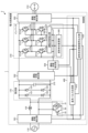
- the converter 130 is a power converter that converts AC power of power supply voltage Vs supplied from the commercial power supply 110 into DC power.
- Converter 130 includes rectifying elements 131 to 134, a reactor 135, a switching element 136, a free wheel diode 137, a diode 138, and a drive circuit 150.
- the converter 130 has a bridge circuit configured by rectifying elements 131 to 134, rectifies the first AC power of the power supply voltage Vs supplied from the commercial power supply 110, and boosts and outputs the rectified DC power.
- the drive circuit 150 generates a drive signal for actually driving the switching element 136 based on a basic pulse generated by a basic pulse generation unit 410 of the control unit 400, which will be described later.
- the inverter 310 is a power converter connected to both ends of the capacitor 210.
- Inverter 310 has switching elements 311a to 311f and free wheel diodes 312a to 312f.
- Inverter 310 turns on and off switching elements 311a to 311f under the control of control unit 400, converts the power output from converter 130 and capacitor 210 into second AC power having a desired amplitude and phase, that is, second AC power. Electric power is generated and output to motor 314.
- the switching elements 311a to 311f are, for example, IGBTs, MOSFETs, bipolar transistors, etc., but are not limited to these.
- Basic pulse generating section 410 has a duty ratio according to the operating state detected by operating state detecting sections 501 to 505, and generates a basic pulse for controlling the operation of switching element 136 of converter 130. Further, the basic pulse generation unit 410 has a duty ratio according to the operating state detected by the operating state detection units 501 to 505, and generates a basic pulse for controlling the operation of the switching elements 311a to 311f of the inverter 310. do.
- the basic pulse is, for example, a PWM (Pulse Width Modulation) signal having a duty ratio according to the operating state detected by the operating state detectors 501 to 505.
- the waveform shape control signal output section 420 is a switching element used when changing the switching waveforms of the switching elements 311a to 311f in the waveform shape changing section 340 of the inverter 310 according to the operating state detected by the operating state detecting sections 501 to 505.
- the waveform shapes of the switching waveforms 311a to 311f are set, and a control signal indicating the set waveform shape is output.
- the waveform shape control signal output unit 420 turns on and off the switching elements 311a to 311f based on the basic pulse generated by the basic pulse generation unit 410 for controlling the operation of the switching elements 311a to 311f of the inverter 310.
- the waveform shape changing unit 340 of the inverter 310 controls the magnitude of the drive signal output to the switching elements 311a to 311f and the timing of outputting the drive signal in order to actually drive the switching elements 311a to 311f.
- the waveform shape control signal output section 420 outputs a control signal for controlling the operation of the waveform shape modification section 340 to the waveform shape modification section 340 .
- the control section 400 controls a waveform shape control signal output section 420 for each waveform shape changing section 340.
- the configuration may include six waveform shape control signal output sections 420.
- control unit 400 acquires the operating states detected by operating state detecting units 501 to 505 from operating state detecting units 501 to 505, and controls converter 130 and Although the operation of the inverter 310 is controlled, the present invention is not limited thereto.
- Control unit 400 can control the operations of converter 130 and inverter 310 based on the operating state acquired from at least one operating state detecting unit among operating state detecting units 501 to 505.
- the operating state detection units 501 to 505 in the above-mentioned example, detect the voltage or current input to each component of the power conversion device 1, the voltage or current output from each component of the power conversion device 1, etc. was detected as the operating state, but the detection target is not limited to these.
- the installation positions of the operating state detection units 501 to 505 are not limited to the example shown in FIG. 1.
- the power conversion device 1 may include the operating state detection section anywhere as long as the operating state can be detected at a position other than that shown in the figure.
- the power converter 1 monitors operating conditions such as noise generated in the power converter 1, motor 314, etc., loss generated in the power converter 1, motor 314, etc., and temperature of each component included in the power converter 1, motor 314, etc.
- An operating state detection section may be provided at a position where these operating states can be detected.
- the control unit 400 also determines the operating state of the air conditioner 2, such as a set temperature for the air conditioner 2 obtained from a remote controller (not shown) used by a user or the like, an operating mode such as heating or cooling for the air conditioner 2, etc. It is possible to use the information of
- both the basic pulse generation unit 410 and the waveform shape control signal output unit 420 operate based on the operating states acquired from the operating state detection units 501 to 505, the control unit 400 operates based on the operating states obtained from the operating state detection units 501 to 505.
- the functions of the waveform shape control signal output section 420 and the waveform shape control signal output section 420 may be combined into one configuration.
- the motor 314 is a load connected to the power converter 1.
- the motor 314 is, for example, a compressor motor for driving a compressor.
- the motor 314 rotates according to the amplitude and phase of the second AC power supplied from the inverter 310, and performs a compression operation.
- the load torque of the motor 314 that drives the compressor can often be regarded as a constant torque load.
- the motor 314 may have a Y-connection, a ⁇ -connection, or a specification in which the Y-connection and the ⁇ -connection can be switched for motor windings (not shown).
- the load connected to the power conversion device 1, that is, the inverter 310 is not limited to the compressor driving motor 314, but may be a fan motor used in the air conditioner 2, or the like. That is, the motor 314 is a compressor motor, a fan motor, or the like.
- the power conversion device 1 can change the waveform shapes of the switching waveforms of the switching elements 311a to 311f of the inverter 310 using the waveform shape control signal output section 420 and the waveform shape changing section 340. Specifically, the power conversion device 1 can change the switching speed, delay time, etc. of the switching elements 311a to 311f of the inverter 310.
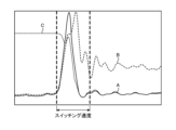
- FIG. 2 shows an example of turn-on Joule loss, turn-on current, and turn-on voltage when the switching speeds of switching elements 311a to 311f of inverter 310 are slowed down in power converter 1 of air conditioner 2 according to Embodiment 1.
- FIG. 3 shows an example of turn-on Joule loss, turn-on current, and turn-on voltage when the switching speed of switching elements 311a to 311f of inverter 310 is increased in power converter 1 of air conditioner 2 according to Embodiment 1.
- A indicates turn-on Joule loss
- B indicates turn-on current
- C indicates turn-on voltage.
- the horizontal axis indicates time.
- the turn-on current is the current flowing through the switching element 311a
- the turn-on voltage is the voltage applied across the switching element 311a
- the turn-on Joule loss is the product of the turn-on current and the turn-on voltage
- the measurement target is the switching element 311a. It is not limited to the element 311a, and other switching elements 311b to 311f may be used.
- FIGS. 2 and 3 show the differences in characteristics depending on the switching speed of the switching elements 311a to 311f of the inverter 310, and the specific values of "slow” and "fast” in the switching speed are not particularly important. . As shown in FIGS.
- the waveform shape changing unit 340 is configured by a digital gate driver.
- the switching elements 311a to 311f of the inverter 310 and the waveform shape changing section 340 are configured by a digital gate driver module.
- the power conversion device 1 can change the switching speed of the switching elements 311a to 311f of the inverter 310 by changing the command value of the software without changing the hardware, and the switching elements 311a to 311f It is possible to control noise and loss generated in a desired state.
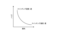
- FIG. 5 is a first diagram showing the effects obtained by changing the switching speeds of the switching elements 311a to 311f of the inverter 310 in the power conversion device 1 of the air conditioner 2 according to the first embodiment.
- the power converter 1 Even if the power converter 1 is operated within the noise range specified by the product in which the power converter 1 is installed, that is, the air conditioner 2, the load state of the motor 314 changes from light load to heavy load. Then, as shown in FIG. 5, the curve representing the characteristics of noise and loss generated in the switching elements 311a to 311f shifts toward the upper right, resulting in an increase in noise. That is, in the power conversion device 1, the heavier the load, the more noise increases. Therefore, the power converter 1 can reduce the noise generated in the switching elements 311a to 311f by slowing down the switching speed of the switching elements 311a to 311f.
- the waveform shape control signal output unit 420 changes the switching elements 311a to 311f so that the noise generated in the switching elements 311a to 311f satisfies the specified requirements. Change the waveform shape of the switching waveform.
- the waveform shape control signal output unit 420 changes the waveform shape of the switching waveform of the switching element 311a so as to suppress loss in the case of light load operation where the operating state is less than the specified load, and changes the waveform shape of the switching waveform of the switching element 311a to suppress the loss.
- the waveform shape of the switching waveform of the switching element 311a is changed so as to suppress noise.
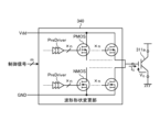
- the waveform shape changing section 340 is connected to the control power supply Vdd and the ground GND.
- the waveform shape changing section 340 changes the number of PMOSs or NMOSs to be operated based on the control signal from the waveform shape control signal output section 420, thereby outputting it to the switching element 311a in each of the turn-on period and the turn-off period.
- the amplitude value of the gate current IG which is the drive signal, can be changed in n ways to adjust the switching speed of the switching element 311a.
- the waveform shape changing unit 340 can increase the absolute value of the gate current IG output to the switching element 311a as the number of PMOSs or NMOSs to be operated increases, and the switching speed of the switching element 311a can be increased. can.
- the waveform shape changing unit 340 can finely adjust the switching speed of the switching element 311a as the number of PMOSs and NMOSs included therein increases, and the faster the response to increase/decrease the gate current IG , the more finely the switching speed of the switching element 311a can be adjusted. It is possible to finely adjust the gate current IG during the switching period.
- the control signal from the waveform shape control signal output section 420 may be an analog signal or a digital signal as long as it can change the number of PMOSs or NMOSs operated by the waveform shape changing section 340. Furthermore, although the example in FIG.
- control signals 7 shows that there are m control signals in parallel from the waveform shape control signal output section 420 to the waveform shape change section 340, this is just an example, and the number of control signals is m. Not limited. The number of control signals may be a number that can indicate whether each PMOS and each NMOS can operate, or it may be one as long as it is an analog signal that indicates voltage or the like.
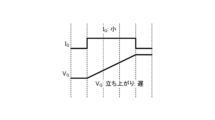
- FIG. 10 shows the relationship between the gate current IG output by the waveform shape changing unit 340 and the gate voltage VG indicating the rising speed of the switching element 311a in the power conversion device 1 included in the air conditioner 2 according to the first embodiment.
- the waveform shape changing unit 340 can divide the turn-on period and change the magnitude of the gate current IG in each period. That is, the waveform shape changing section 340 can finely adjust the magnitude of the gate current IG during one turn-on period.
- the power converter 1 can reduce the noise generated in the switching element 311a while reducing the noise generated in the switching element 311a, as shown in FIG. 6, compared to the case where the same gate current IG is output during the turn-on period. control can be performed to reduce the loss caused by
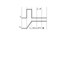
- FIG. 11 shows an example of the relationship between the basic pulse outputted by the basic pulse generation unit 410 and the gate current IG outputted by the waveform shape changing unit 340 in the power conversion device 1 included in the air conditioner 2 according to the first embodiment. It is a diagram. In FIG. 11, it is assumed that
- the waveform shape changing section 340 changes the waveform shape of the switching waveform of the switching element 311a between the turn-on period and the turn-off period of the switching element 311a based on the control signal output from the waveform shape control signal output section 420. At least one period can be divided into two or more periods, and the amplitude of the gate current IG to the switching element 311a can be changed to a different magnitude in each divided period. Further, the waveform shape changing section 340 includes a plurality of transistors, and changes the amplitude of the gate current IG by changing the number of transistors to be operated based on the control signal output from the waveform shape control signal output section 420. can do. Thereby, the air conditioner 2 can change the noise and loss generated in the switching element 311a according to the operating state.
- the waveform shape changing section 340 can change the output pattern of the gate current IG every switching period of the switching element 311a.
- the waveform shape changing unit 340 can change the switching waveform to a different waveform shape every switching period of the switching element 311a while the power conversion device 1 is in operation.
- the waveform shape changing unit 340 changes the waveform shape of the switching waveform of the switching element 311a while at least one of the motors 314 included in the air conditioner 2, such as a compressor motor and a fan motor, is rotating.
- the waveform shape control signal output section 420 can change the waveform shape of the switching waveform of the switching element 311a at the same cycle as the switching cycle of the switching element 311a.
- the waveform shape control signal output unit 420 may change the waveform shape of the switching waveform of the switching element 311a at a cycle that is a positive integer multiple of the switching cycle of the switching element 311a.
- the waveform shape control signal output section 420 generates switching waveforms of the switching elements 311a to 311f of the inverter 310 based on the basic pulses obtained from the basic pulse generation section 410 and the operating states obtained from the operating state detection sections 501 to 505. Set the waveform shape to change the shape. In this way, in the control section 400, the waveform shape control signal output section 420 turns on the switching elements 311a to 311f determined by the basic pulse generation section 410 based on the operating state acquired from the operating state detection sections 501 to 505. Set the waveform shape of the switching waveform at the turn-off timing and turn-off timing.
- the waveform shape control signal output section 420 outputs a control signal that can change the magnitude and output timing of the drive signal according to the set waveform shape to the waveform shape change section 340 (step S2).
- the processor 91 is a CPU (Central Processing Unit, also referred to as a central processing unit, a processing unit, an arithmetic unit, a microprocessor, a microcomputer, a processor, a DSP (Digital Signal Processor)), or a system LSI (Large Scale Intel). gration).
- the memory 92 includes RAM (Random Access Memory), ROM (Read Only Memory), flash memory, EPROM (Erasable Programmable Read Only Memory), and EEP. Non-volatile or volatile memory such as ROM (registered trademark) (Electrically Erasable Programmable Read Only Memory) An example is semiconductor memory.
- the memory 92 is not limited to these, and may be a magnetic disk, an optical disk, a compact disk, a mini disk, or a DVD (Digital Versatile Disc).
- the air conditioner 2 can control the generation of noise and loss according to the operating state. Furthermore, the air conditioner 2 can change the switching speed of the switching elements 311a to 311f while suppressing an increase in circuit scale.
- the air conditioner 2 finely adjusts the gate current IG or the gate voltage VG output to the switching elements 311a to 311f in one switching period, so that the switching element 311a, which could not be realized with the method of Patent Document 1, etc. It is possible to realize a switching waveform shape of ⁇ 311f.
- Embodiment 2 In the first embodiment, a case has been described in which the waveform shape of the switching waveform of the switching elements 311a to 311f of the inverter 310 is changed in the power conversion device 1 of the air conditioner 2. In Embodiment 2, a case will be described in which the waveform shape of the switching waveform of the switching element 136 of the converter 130 is changed in the power conversion device 1 of the air conditioner 2.
- FIG. 14 is a diagram showing a configuration example of the air conditioner 2 according to the second embodiment.
- Air conditioner 2 includes power converter 1 and motor 314.
- Power conversion device 1 is connected to commercial power source 110 and motor 314.
- the power conversion device 1 converts the first AC power of the power supply voltage Vs supplied from the commercial power supply 110 into second AC power having a desired amplitude and phase, and supplies the second AC power to the motor 314.
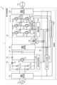
- the power converter 1 includes an operating state detecting section 501, a converter 130, a capacitor 210, an operating state detecting section 502, an inverter 310, an operating state detecting section 503, an operating state detecting section 504, and an operating state detecting section 505 and a control unit 400.
- the power converter 1 of the second embodiment shown in FIG. 14 is different from the power converter 1 of the first embodiment shown in FIG. , the drive circuit 150 is removed from the converter 130 and a waveform shape changing section 140 is added. Moreover, the power converter 1 of the second embodiment shown in FIG. 14 is different from the power converter 1 of the first embodiment shown in FIG. is being changed. Specifically, basic pulse generation section 410 outputs a basic pulse for controlling the operation of switching element 136 of converter 130 to waveform shape control signal output section 420, and controls the operation of switching elements 311a to 311f of inverter 310. A basic pulse for control is output to the inverter 310. Further, the waveform shape control signal output section 420 outputs a control signal for controlling the operation of the waveform shape modification section 140 to the waveform shape modification section 140.
- the drive circuit 350 In the inverter 310, the drive circuit 350 generates drive signals for actually driving the switching elements 311a to 311f based on the basic pulses generated by the basic pulse generation unit 410 of the control unit 400.
- waveform shape control signal output section 420 changes the switching waveform of switching element 136 in waveform shape changing section 140 of converter 130 according to the operating state detected by operating state detecting sections 501 to 505.
- the waveform shape of the switching waveform of the switching element 136 at that time is set, and a control signal indicating the set waveform shape is output.
- waveform shape control signal output unit 420 The waveform shape changing unit 140 of 130 controls the magnitude of the drive signal output to the switching element 136 and the timing of outputting the drive signal in order to actually drive the switching element 136.
- Waveform shape control signal output section 420 outputs a control signal for controlling the operation of waveform shape modification section 140 to waveform shape modification section 140 .
- the waveform shape changing unit 140 can change the waveform shape of the switching waveform of the switching element 136.
- the waveform shape changing section 140 can output two or more waveform shapes as the waveform shape of the switching waveform of the switching element 136.
- the waveform shape changing section 140 is included in the converter 130, which is a power converter including a switching element 136, as shown in FIG.
- the configuration of waveform shape changing section 140 is similar to the configuration of waveform shape changing section 340 of Embodiment 1 shown in FIG. That is, the waveform shape changing section 140 and the switching element 136 are configured by one digital gate driver module. Further, like the waveform shape changing unit 340, the waveform shape changing unit 140 may adjust the gate voltage VG output to the switching element 136 instead of the gate current IG outputting to the switching element 136 as a drive signal. .
- the waveform shape changing section 140 changes the waveform shape of the switching waveform of the switching element 136 between the turn-on period and the turn-off period of the switching element 136 based on the control signal output from the waveform shape control signal output section 420. At least one period can be divided into two or more periods, and the amplitude of the gate current IG or gate voltage VG applied to the switching element 136 can be changed to a different magnitude in each divided period.
- the waveform shape changing section 140 includes a plurality of transistors, and changes the number of transistors to be operated based on the control signal output from the waveform shape control signal output section 420, thereby increasing the gate current IG or the gate voltage V. The amplitude of G can be changed.
- power conversion device 1 performs the same operation as in the first embodiment to change the waveform shape of the switching waveform of switching element 136 of converter 130 using waveform shape control signal output section 420 and waveform shape modification section 140. Can be changed. Furthermore, the air conditioner 2 can change the noise and loss generated in the switching element 136 depending on the operating state.
- the waveform shape control signal output section 420 of the control section 400 outputs the output signal of the operation detected by the operation state detection sections 501 to 505.
- the waveform shape changing section 140 of the converter 130 outputs a control signal for changing the switching waveform of the switching element 136.
- the waveform shape changing unit 140 of the converter 130 changes the gate current IG or gate voltage VG output to the switching element 136 based on the control signal output from the waveform shape control signal output unit 420.
- the waveform shape of the switching waveform of 136 is changed.
- the waveform shape changing section 140 can change the waveform shape of the switching waveform of the switching element 136 in the same way that the waveform shape changing section 340 of the first embodiment changes the waveform shape of the switching waveform of the switching element 311a. can.
- the air conditioner 2 can control the generation of noise and loss according to the operating state.
- the air conditioner 2 can change the switching speed of the switching element 136 while suppressing an increase in circuit scale.
- the air conditioner 2 finely adjusts the gate current IG or gate voltage VG output to the switching element 136 during one switching period, thereby achieving switching of the switching element 136 that could not be achieved with the method disclosed in Patent Document 1.
- a waveform shape of a waveform can be realized.
- FIG. 15 is a first diagram showing a rectifying portion of converter 130 included in power conversion device 1 of air conditioner 2 according to the second embodiment.
- FIG. 16 is a second diagram showing the rectifying portion of the converter 130 included in the power conversion device 1 of the air conditioner 2 according to the second embodiment.
- FIG. 17 is a third diagram showing the rectifying part of the converter 130 included in the power conversion device 1 of the air conditioner 2 according to the second embodiment. 15 to 17, only the differences from FIG. 14 are shown, and the description of the waveform shape changing unit 140 is omitted. As shown in FIG.
- the waveform shape changing section 140 changes the waveform shape of the switching waveform of the switching elements 136a to 136d. May be changed.
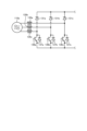
- the waveform shape changing unit 140 in a configuration in which the converter 130 includes a reactor 135, rectifying elements 131 to 134, a switching element 136, a freewheeling diode 137, and rectifying elements 131a to 134a, the waveform shape changing unit 140 The waveform shape of the switching waveform of 136 may be changed. Further, as shown in FIG.
- the connected commercial power source is a three-phase AC power source 110a
- the converter 130 includes reactors 135a to 135c, rectifying elements 131a to 131c, switching elements 136a to 136c, and
- the waveform shape changing section 140 may change the waveform shape of the switching waveforms of the switching elements 136a to 136c.
- Embodiment 3 In the first embodiment, a case has been described in which the waveform shape of the switching waveform of the switching elements 311a to 311f of the inverter 310 is changed in the power conversion device 1 of the air conditioner 2. In the second embodiment, a case has been described in which the waveform shape of the switching waveform of the switching element 136 of the converter 130 is changed in the power conversion device 1 of the air conditioner 2. In the third embodiment, in the power conversion device 1 of the air conditioner 2, the waveform shape of the switching waveform of the switching elements 311a to 311f of the inverter 310 is changed, and the waveform shape of the switching waveform of the switching element 136 of the converter 130 is changed. Let me explain the case.
- a power conversion device 1 according to the third embodiment shown in FIG. 18 is different from the power conversion device 1 according to the first embodiment shown in FIG. It is something. Moreover, the power converter 1 of the third embodiment shown in FIG. 18 is different from the power converter 1 of the first embodiment shown in FIG. is being changed. Specifically, basic pulse generation section 410 outputs a basic pulse for controlling the operation of switching elements 311a to 311f of inverter 310 to waveform shape control signal output section 420, and controls the operation of switching element 136 of converter 130. A basic pulse for control is output to the waveform shape control signal output section 420.
- the waveform shape control signal output section 420 outputs a control signal for controlling the operation of the waveform shape changing section 340 to the waveform shape changing section 340, and outputs a control signal for controlling the operation of the waveform shape changing section 140. It is output to the waveform shape changing section 140.
- the waveform shape control signal output section 420 performs the operation described in the first embodiment as well as the operation described in the second embodiment. Further, in this embodiment, waveform shape changing section 340 performs the same operation as described in Embodiment 1, and waveform shape changing section 140 performs the same operation as described in Embodiment 2. conduct. Thereby, by performing the same operation as in the first embodiment, the power converter 1 changes the waveforms of the switching waveforms of the switching elements 311a to 311f of the inverter 310 by the waveform shape control signal output section 420 and the waveform shape changing section 340. Can change shape. Furthermore, by performing the same operation as in the second embodiment, power converter 1 changes the waveform shape of the switching waveform of switching element 136 of converter 130 using waveform shape control signal output section 420 and waveform shape changing section 140. can do.
- one of the waveform shape changing units 140 and 340 changes the waveform shape of the switching waveform of the switching element at a certain timing, and the other changes the waveform shape of the switching waveform of the switching element. It is also possible to perform control that does not change the shape.
- the switching elements whose switching waveforms are changed by the waveform shape changing units 140 and 340 of the power converter 1 are among the one or more power converters that perform power conversion in the power converter 1.
- the waveform shape of the switching waveform of the switching elements 311a to 311f is changed.
- the waveform shape changing section 140 of the converter 130 changes the gate current IG or gate voltage VG output to the switching element 136 based on the control signal output from the waveform shape control signal output section 420.
- the waveform shape of the switching waveform of the switching element 136 is changed.
- the air conditioner 2 can control the generation of noise and loss according to the operating state.
- the air conditioner 2 can change the switching speeds of the switching elements 311a to 311f and the switching element 136 while suppressing an increase in circuit scale.
- the power conversion device 1 can detect the current flowing through each part, the voltage applied to each part, etc. with respect to the load state, based on the current value, for example, the detected value of the operating state detection sections 501 to 505.
- the power converter 1 can detect the temperature based on a detected value of a temperature sensor (not shown) of an indoor unit included in the air conditioner 2, a detected value of a temperature sensor (not shown) of an outdoor unit, etc., regarding the load state. I can do it.
- the power conversion device 1 may include a temperature sensor around the board of the inverter 310 to detect the temperature around the board of the inverter 310, or may include a temperature sensor around the motor 314 to detect the temperature around the motor 314. may be detected.
- a heating low temperature condition which is an operation mode in an environment where the outside temperature is lower than the heating rated condition.
- the heating low temperature condition has a larger load than the heating rated condition, and the power consumption is even higher.
- the waveform shape control signal output unit 420 performs light load operation when the operating state of the air conditioner 2 is the cooling intermediate condition and heating intermediate condition, and when the operating state of the air conditioner 2 is the cooling rated condition and the heating rated condition. conditions, and other air temperature conditions, heavy load operation shall be performed.
- the waveform shape control signal output unit 420 performs light load operation when the difference between the outside temperature and the set temperature of the air conditioner 2 is less than a specified threshold value, and controls the difference between the outside temperature and the set temperature of the air conditioner 2. If the difference is greater than or equal to a specified threshold, heavy load operation may be performed.
- Embodiment 5 A case will be described in which an adaptive observer is applied as sensorless control of the motor 314 in the power conversion device 1 of Embodiment 1 to Embodiment 4. Specifically, the power conversion device 1 of Embodiment 1 will be explained as an example.
- the speed estimating device 101 includes a model deviation calculation unit 11 that calculates a model deviation ⁇ based on a voltage vector, a current vector, and an estimated angular velocity ⁇ r , and a first and a first angular velocity estimation unit 21 that calculates the estimated angular velocity ⁇ r1 .
- the speed estimating device 101 also includes a second angular velocity estimator 22 that calculates a second estimated angular velocity ⁇ r2 as a high frequency component of the actual angular velocity based on a specific high frequency component included in the model deviation ⁇ , and a first estimated angular velocity and an adder 23 that calculates the estimated angular velocity ⁇ r by adding the second estimated angular velocity ⁇ r2 to the angular velocity ⁇ r1 .
- the velocity estimating device 101 is characterized in that it includes a second angular velocity estimating section 22. The speed estimation device 101 feeds back the sum of the first estimated angular velocity ⁇ r1 and the second estimated angular velocity ⁇ r2 to the model deviation calculation unit 11 as the estimated angular velocity ⁇ r .
- the model deviation calculation unit 11 includes a current estimator 12 that calculates and outputs an estimated magnetic flux vector and an estimated current vector based on the voltage vector, current vector, and estimated angular velocity ⁇ r of the motor 314, and a current estimator 12 that calculates and outputs an estimated magnetic flux vector and an estimated current vector, and a current vector that calculates a current vector from the estimated current vector.
- a subtracter 13 that calculates and outputs a current deviation vector; and a deviation calculator 14 that receives the current deviation vector, extracts the orthogonal component of the estimated magnetic flux vector as a scalar quantity, and outputs this value as a model deviation ⁇ . , is provided.
- the current estimator 12 estimates the current and magnetic flux from the state equation of the motor 314.
- the motor 314 is a general embedded magnet type synchronous AC motor, but even if the motor 314 is other than an embedded magnet type synchronous AC motor, the current estimator 12 can be used in the same manner as long as the state equation can be formulated.
- the current can be estimated using the following method. Examples of the motor 314 other than the embedded magnet type synchronous AC motor include a surface magnet type synchronous motor, an induction motor, and the like. Further, in this embodiment, a rotary motor will be described, but the same technique can also be applied to a direct drive motor. The reason is that a direct-acting motor can be interpreted as a rotary motor with an infinite rotor radius.
- FIG. 21 is a diagram showing a configuration example of an air conditioner 2 according to the sixth embodiment.
- Air conditioner 2 includes power converter 1 and motor 314.
- the configuration of the power converter 1 according to the sixth embodiment shown in FIG. 21 is the same as the power converter 1 according to the first embodiment shown in FIG.
- Converter 130 is a rectifier that has a bridge circuit configured by rectifying elements 131 to 134, and rectifies first AC power of power supply voltage Vs supplied from commercial power supply 110 and outputs the rectifier.
- control unit 400 outputs second AC power including pulsations corresponding to the pulsations of power flowing into capacitor 210 from converter 130, which is a rectifier, from inverter 310 to motor 314, which is a load.
- the operation of the inverter 310 is controlled accordingly.
- the pulsation corresponding to the pulsation of the power flowing into the capacitor 210 is a pulsation that varies depending on the frequency of the pulsation of the power flowing into the capacitor 210, for example.
- the control unit 400 suppresses the current flowing through the capacitor 210.
- the control unit 400 does not need to use all of the detection values obtained from each detection unit, and may perform control using some of the detection values.
- the load generated by the inverter 310 and the motor 314 can be considered as a constant load, and when viewed from the current output from the capacitor 210, the capacitor 210 has a constant current load.
- the current flowing from converter 130 is defined as current I1
- the current flowing through inverter 310 is defined as current I2
- the current flowing from capacitor 210 is defined as current I3.
- the current I2 is a combination of the current I1 and the current I3.
- Current I3 can be expressed as the difference between current I2 and current I1, ie, current I2-current I1.
- the current I3 has a positive direction in which the capacitor 210 is discharged, and a negative direction in which the capacitor 210 is charged. That is, current may flow into the capacitor 210, and current may flow out of the capacitor 210.
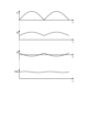
- FIG. 22 shows, as a comparative example, an example of each of the currents I1 to I3 and the capacitor voltage Vdc of the capacitor 210 when the current output from the converter 130 is smoothed by the capacitor 210 and the current I2 flowing to the inverter 310 is kept constant.
- It is a diagram. From the top, current I1, current I2, current I3, and capacitor voltage Vdc of capacitor 210 generated in response to current I3 are shown.
- the vertical axes of currents I1, I2, and I3 indicate current values, and the vertical axis of capacitor voltage Vdc indicates voltage values. All horizontal axes indicate time t. Note that the carrier components of the inverter 310 are actually superimposed on the currents I2 and I3, but this is omitted here.
- the control unit 400 detects the pulsation in accordance with the operating state detected by the operating state detecting units 501 to 505 from the inverter 310, which is a power converter, to the motor 314 connected to the inverter 310.
- the operation of the inverter 310 is controlled so as to be superimposed on the drive pattern, and the charging/discharging current of the capacitor 210 is suppressed.
- the air conditioner 2 can suppress deterioration of the smoothing capacitor 210.
- FIG. 24 is a diagram showing a configuration example of the air conditioner 2 according to the seventh embodiment.
- Air conditioner 2 includes power converter 1 and motor 314.
- the power conversion device 1 according to the seventh embodiment shown in FIG. 24 differs from the power conversion device 1 according to the first embodiment shown in FIG. 30 has been added.
- the rectifier 170 includes a rectifier circuit including four rectifier elements 131 to 134, and a capacitor 210 that is connected between the output terminals of the rectifier circuit and smoothes the voltage of the full-wave rectified waveform output from the rectifier circuit. be done.
- the rectifier 170 rectifies and outputs the first AC power supplied from the commercial power source 110.
- the shorting section 30 short-circuits the commercial power supply 110 via the reactor 135.
- the shorting section 30 includes a diode bridge 31 connected in parallel to the commercial power supply 110 via a reactor 135, and a shorting element 32 connected to both output ends of the diode bridge 31.
- the shorting element 32 is a metal oxide semiconductor field effect transistor
- the gate of the shorting element 32 is connected to the control section 400, and the shorting element 32 is turned on and off by a drive signal from the control section 400.
- the shorting element 32 is turned on, the commercial power supply 110 is short-circuited via the reactor 135 and the diode bridge 31.
- the control unit 400 controls the short circuit operation of the short circuit unit 30.
- the control unit 400 controls the on/off of the short circuit element 32 by current open loop control in the short circuit operation mode so that the short circuit unit 30 is short circuited at least twice or more during a half cycle of the power supply.
- the control unit 400 short-circuits the short circuit unit 30 at least twice during a half cycle of the commercial power supply 110 based on the load condition.
- the air conditioner 2 can suppress fluctuations in the DC voltage even when changing the number of switching times of the shorting section 30 that shorts the commercial power source 110 in accordance with the load condition.
- FIG. 25 is a diagram showing a configuration example of an air conditioner 900 according to Embodiment 8.
- Air conditioner 900 according to Embodiment 8 is provided to explain in more detail the configuration of air conditioner 2 described in Embodiment 1.
- the air conditioner 900 according to the eighth embodiment may be the air conditioner 2 described in the second to seventh embodiments. Note that in FIG. 25, components having the same functions as in the first embodiment are given the same reference numerals as in the first embodiment.
- a compressor 315 incorporating the motor 314 in the first embodiment, a four-way valve 902, an indoor heat exchanger 906, an expansion valve 908, and an outdoor heat exchanger 910 are connected via a refrigerant pipe 912. installed.
- a compression mechanism 904 that compresses the refrigerant and a motor 314 that operates the compression mechanism 904 are provided inside the compressor 315.
- the air conditioner 900 can perform heating operation or cooling operation by switching the four-way valve 902.
- the compression mechanism 904 is driven by a variable speed controlled motor 314.
- the refrigerant is pressurized by the compression mechanism 904 and sent out, passing through the four-way valve 902, indoor heat exchanger 906, expansion valve 908, outdoor heat exchanger 910, and four-way valve 902. Returning to the compression mechanism 904.
- the indoor heat exchanger 906 acts as a condenser and releases heat, and the outdoor heat exchanger 910 acts as an evaporator and absorbs heat.
- the outdoor heat exchanger 910 acts as a condenser and releases heat, and the indoor heat exchanger 906 acts as an evaporator and absorbs heat.
- the expansion valve 908 reduces the pressure of the refrigerant and expands it.
- the digital gate driver module configured by the waveform shape changing section 340 and the switching elements 311a to 311f included in the inverter 310 has a high surge voltage when the switching speed is high. Therefore, a lot of electromagnetic noise is generated.
- the air conditioner 900 uses a flammable refrigerant, there is a possibility that the refrigerant will be combusted due to discharge caused by electromagnetic noise when the refrigerant leaks. Therefore, the air conditioner 900 sets the switching speed of the digital gate driver module included in the power conversion device 1 according to the combustibility of the refrigerant used in the air conditioner 900.
- the air conditioner 900 can reduce surge voltage by slowing down the switching speed of the digital gate driver module, and by suppressing the occurrence of discharge caused by electromagnetic noise, even if refrigerant leaks from the air conditioner 900, the surge voltage can be reduced. Burning can be prevented.
- Refrigerants used in the air conditioner 900 include, for example, R1234yf, R1234ze (E), R1243zf, HFO1123, HFO1132 (E), R1132a, CF3I, R290, R463A, R466A, R454A, R454B, and R454C.
- 1 Power conversion device 2,900 Air conditioner, 11 Model deviation calculation unit, 12 Current estimator, 13 Subtractor, 14 Deviation calculation unit, 21 First angular velocity estimation unit, 22 Second angular velocity estimation unit, 23 Addition Vessels, 30 short circuit, 31 diode bridges, 32 short circuit elements, 101 speed estimation devices, 110, 110A commercial power supply, 130 converters, 131-134, 131a, 131b, 131C rectus elements, 135, 135a -135C, 136 , 136a to 136d, 311a to 311f switching element, 137, 137a to 137d, 312a to 312f freewheeling diode, 138 diode, 140, 340 waveform shape changing unit, 150, 350 drive circuit, 170 rectifier, 210 capacitor, 310 Inverter, 314 Motor, 315 Compressor, 400 Control unit, 410 Basic pulse generation unit, 420 Waveform shape control signal output unit, 501 to 505 Operating state detection unit, 902 Four-way valve, 904
Abstract
Ce climatiseur (2) pour effectuer une commande de climatisation comprend : un ou plusieurs éléments de commutation inclus dans au moins un convertisseur de puissance parmi un ou plusieurs convertisseurs de puissance qui effectuent une conversion de puissance; une unité de changement de forme d'onde qui peut changer la forme d'onde de la forme d'onde de commutation de l'élément de commutation; des unités de détection d'état de fonctionnement (501-505) qui détectent l'état opérationnel du climatiseur (2); et une unité d'émission de signal de commande de forme d'onde (420) qui émet un signal de commande lors du changement de la forme d'onde de commutation de l'élément de commutation dans l'unité de changement de forme d'onde en fonction de l'état opérationnel.
Priority Applications (1)
| Application Number | Priority Date | Filing Date | Title |
|---|---|---|---|
| PCT/JP2022/023163 WO2023238293A1 (fr) | 2022-06-08 | 2022-06-08 | Climatiseur |
Applications Claiming Priority (1)
| Application Number | Priority Date | Filing Date | Title |
|---|---|---|---|
| PCT/JP2022/023163 WO2023238293A1 (fr) | 2022-06-08 | 2022-06-08 | Climatiseur |
Publications (1)
| Publication Number | Publication Date |
|---|---|
| WO2023238293A1 true WO2023238293A1 (fr) | 2023-12-14 |
Family
ID=89117746
Family Applications (1)
| Application Number | Title | Priority Date | Filing Date |
|---|---|---|---|
| PCT/JP2022/023163 WO2023238293A1 (fr) | 2022-06-08 | 2022-06-08 | Climatiseur |
Country Status (1)
| Country | Link |
|---|---|
| WO (1) | WO2023238293A1 (fr) |
Citations (10)
| Publication number | Priority date | Publication date | Assignee | Title |
|---|---|---|---|---|
| JPH11150462A (ja) * | 1997-11-19 | 1999-06-02 | Meidensha Corp | スイッチング制御回路 |
| JP2002354826A (ja) * | 2001-05-24 | 2002-12-06 | Isao Takahashi | インバータ制御方法およびその装置 |
| JP3485047B2 (ja) * | 1999-11-24 | 2004-01-13 | 三菱電機株式会社 | 空気調和機 |
| JP2004312817A (ja) * | 2003-04-03 | 2004-11-04 | Mitsubishi Electric Corp | 電力変換装置およびその電力変換装置を備える電力変換システム装置 |
| JP2009118650A (ja) * | 2007-11-07 | 2009-05-28 | Mitsubishi Electric Corp | 電力変換装置 |
| JP2012157215A (ja) * | 2011-01-28 | 2012-08-16 | Sanken Electric Co Ltd | ドライブ回路及びスイッチング電源装置 |
| JP2015171226A (ja) * | 2014-03-06 | 2015-09-28 | 三菱電機株式会社 | インバータ装置及び空気調和機 |
| WO2017212794A1 (fr) * | 2016-06-08 | 2017-12-14 | 三菱電機株式会社 | Appareil d'estimation de vitesse pour moteur en ca, appareil d'entraînement pour moteur en ca, compresseur de réfrigérant, et appareil de cycle de congélation |
| WO2019176077A1 (fr) * | 2018-03-16 | 2019-09-19 | 新電元工業株式会社 | Circuit de commande d'interrupteur à semi-conducteur et dispositif d'alimentation à découpage |
| JP2022048476A (ja) * | 2020-09-15 | 2022-03-28 | 株式会社東芝 | 駆動制御回路 |
-
2022
- 2022-06-08 WO PCT/JP2022/023163 patent/WO2023238293A1/fr unknown
Patent Citations (10)
| Publication number | Priority date | Publication date | Assignee | Title |
|---|---|---|---|---|
| JPH11150462A (ja) * | 1997-11-19 | 1999-06-02 | Meidensha Corp | スイッチング制御回路 |
| JP3485047B2 (ja) * | 1999-11-24 | 2004-01-13 | 三菱電機株式会社 | 空気調和機 |
| JP2002354826A (ja) * | 2001-05-24 | 2002-12-06 | Isao Takahashi | インバータ制御方法およびその装置 |
| JP2004312817A (ja) * | 2003-04-03 | 2004-11-04 | Mitsubishi Electric Corp | 電力変換装置およびその電力変換装置を備える電力変換システム装置 |
| JP2009118650A (ja) * | 2007-11-07 | 2009-05-28 | Mitsubishi Electric Corp | 電力変換装置 |
| JP2012157215A (ja) * | 2011-01-28 | 2012-08-16 | Sanken Electric Co Ltd | ドライブ回路及びスイッチング電源装置 |
| JP2015171226A (ja) * | 2014-03-06 | 2015-09-28 | 三菱電機株式会社 | インバータ装置及び空気調和機 |
| WO2017212794A1 (fr) * | 2016-06-08 | 2017-12-14 | 三菱電機株式会社 | Appareil d'estimation de vitesse pour moteur en ca, appareil d'entraînement pour moteur en ca, compresseur de réfrigérant, et appareil de cycle de congélation |
| WO2019176077A1 (fr) * | 2018-03-16 | 2019-09-19 | 新電元工業株式会社 | Circuit de commande d'interrupteur à semi-conducteur et dispositif d'alimentation à découpage |
| JP2022048476A (ja) * | 2020-09-15 | 2022-03-28 | 株式会社東芝 | 駆動制御回路 |
Similar Documents
| Publication | Publication Date | Title |
|---|---|---|
| JP5892997B2 (ja) | コンバータ回路、並びにそれを備えたモータ駆動制御装置、空気調和機、及び冷蔵庫 | |
| JP5633442B2 (ja) | インバータ制御装置及び冷凍空調装置 | |
| JP5558529B2 (ja) | モーター駆動制御装置、圧縮機、送風機、空気調和機及び冷蔵庫又は冷凍庫 | |
| AU2011377665B2 (en) | Heat pump device, heat pump system, and inverter control method | |
| US11018615B2 (en) | Motor drive device and air conditioner | |
| CN109937531B (zh) | 电力转换装置及冷冻空调机器 | |
| JP5505528B1 (ja) | 消費電力削減装置 | |
| WO2017208873A1 (fr) | Appareil d'entraînement de moteur, et dispositif électrique comportant un compresseur utilisant ledit appareil | |
| JP2017112776A (ja) | コンバータ装置、駆動制御装置、モータ、およびコンプレッサ | |
| KR20140109165A (ko) | 전력변환장치 및 이를 포함하는 공기조화기 | |
| JP6541074B2 (ja) | 三相倍電圧整流回路、インバータ装置、空気調和機、三相倍電圧整流回路の制御方法及びプログラム | |
| JP2022118033A (ja) | 空気調和機 | |
| WO2023238293A1 (fr) | Climatiseur | |
| JP2010115110A (ja) | 空気調和装置のインバータ制御装置 | |
| WO2023238291A1 (fr) | Dispositif de conversion de puissance, dispositif d'entraînement de moteur et dispositif d'application de cycle de réfrigération | |
| JP3546786B2 (ja) | 空気調和機 | |
| KR20140108956A (ko) | 전력변환장치 및 이를 포함하는 공기조화기 | |
| JP4197974B2 (ja) | モータ制御装置及びモータの制御方法 | |
| KR20140096627A (ko) | 전력변환장치 및 이를 포함하는 공기조화기 | |
| JP2020137329A (ja) | インバータ装置 | |
| WO2023238292A1 (fr) | Dispositif de conversion de puissance, dispositif d'entraînement de moteur et équipement appliqué au cycle de réfrigération | |
| KR101936631B1 (ko) | 모터 구동장치 및 이를 구비하는 공기조화기 | |
| WO2023238296A1 (fr) | Dispositif d'énergie de puissance électrique, dispositif d'entraînement de moteur et appareil d'application de cycle de réfrigération | |
| JP2005065449A (ja) | モータ制御装置 | |
| JP7045529B2 (ja) | 電力変換装置および空気調和機 |
Legal Events
| Date | Code | Title | Description |
|---|---|---|---|
| 121 | Ep: the epo has been informed by wipo that ep was designated in this application |
Ref document number: 22945796 Country of ref document: EP Kind code of ref document: A1 |