WO2023238293A1 - Air conditioner - Google Patents
Air conditioner Download PDFInfo
- Publication number
- WO2023238293A1 WO2023238293A1 PCT/JP2022/023163 JP2022023163W WO2023238293A1 WO 2023238293 A1 WO2023238293 A1 WO 2023238293A1 JP 2022023163 W JP2022023163 W JP 2022023163W WO 2023238293 A1 WO2023238293 A1 WO 2023238293A1
- Authority
- WO
- WIPO (PCT)
- Prior art keywords
- air conditioner
- waveform shape
- switching
- waveform
- switching element
- Prior art date
Links
- 238000006243 chemical reaction Methods 0.000 claims abstract description 88
- 238000001514 detection method Methods 0.000 claims abstract description 35
- 238000004378 air conditioning Methods 0.000 claims abstract description 14
- 239000003990 capacitor Substances 0.000 claims description 51
- 238000010438 heat treatment Methods 0.000 claims description 18
- 239000003507 refrigerant Substances 0.000 claims description 15
- 238000001816 cooling Methods 0.000 claims description 14
- 230000010349 pulsation Effects 0.000 claims description 8
- 238000007599 discharging Methods 0.000 claims description 2
- VPAYJEUHKVESSD-UHFFFAOYSA-N trifluoroiodomethane Chemical compound FC(F)(F)I VPAYJEUHKVESSD-UHFFFAOYSA-N 0.000 claims description 2
- 230000008859 change Effects 0.000 abstract description 33
- 238000010586 diagram Methods 0.000 description 46
- 238000000034 method Methods 0.000 description 14
- 230000006835 compression Effects 0.000 description 9
- 238000007906 compression Methods 0.000 description 9
- 230000007246 mechanism Effects 0.000 description 8
- 230000004048 modification Effects 0.000 description 7
- 238000012986 modification Methods 0.000 description 7
- 230000004907 flux Effects 0.000 description 6
- 230000000630 rising effect Effects 0.000 description 6
- 239000004065 semiconductor Substances 0.000 description 6
- 230000000694 effects Effects 0.000 description 5
- 229910044991 metal oxide Inorganic materials 0.000 description 5
- 150000004706 metal oxides Chemical class 0.000 description 5
- 230000007423 decrease Effects 0.000 description 4
- 230000006870 function Effects 0.000 description 4
- 230000008569 process Effects 0.000 description 4
- 230000001360 synchronised effect Effects 0.000 description 4
- 230000003044 adaptive effect Effects 0.000 description 3
- 230000006866 deterioration Effects 0.000 description 3
- 230000004044 response Effects 0.000 description 3
- 230000000052 comparative effect Effects 0.000 description 2
- 230000003247 decreasing effect Effects 0.000 description 2
- 230000005669 field effect Effects 0.000 description 2
- 238000009499 grossing Methods 0.000 description 2
- 239000000284 extract Substances 0.000 description 1
- 230000006698 induction Effects 0.000 description 1
- 238000009434 installation Methods 0.000 description 1
- 238000005259 measurement Methods 0.000 description 1
- 230000003287 optical effect Effects 0.000 description 1
- 239000007787 solid Substances 0.000 description 1
- 238000004804 winding Methods 0.000 description 1
Images


Classifications
-
- H—ELECTRICITY
- H02—GENERATION; CONVERSION OR DISTRIBUTION OF ELECTRIC POWER
- H02M—APPARATUS FOR CONVERSION BETWEEN AC AND AC, BETWEEN AC AND DC, OR BETWEEN DC AND DC, AND FOR USE WITH MAINS OR SIMILAR POWER SUPPLY SYSTEMS; CONVERSION OF DC OR AC INPUT POWER INTO SURGE OUTPUT POWER; CONTROL OR REGULATION THEREOF
- H02M1/00—Details of apparatus for conversion
- H02M1/08—Circuits specially adapted for the generation of control voltages for semiconductor devices incorporated in static converters
-
- H—ELECTRICITY
- H02—GENERATION; CONVERSION OR DISTRIBUTION OF ELECTRIC POWER
- H02M—APPARATUS FOR CONVERSION BETWEEN AC AND AC, BETWEEN AC AND DC, OR BETWEEN DC AND DC, AND FOR USE WITH MAINS OR SIMILAR POWER SUPPLY SYSTEMS; CONVERSION OF DC OR AC INPUT POWER INTO SURGE OUTPUT POWER; CONTROL OR REGULATION THEREOF
- H02M3/00—Conversion of dc power input into dc power output
- H02M3/02—Conversion of dc power input into dc power output without intermediate conversion into ac
- H02M3/04—Conversion of dc power input into dc power output without intermediate conversion into ac by static converters
- H02M3/10—Conversion of dc power input into dc power output without intermediate conversion into ac by static converters using discharge tubes with control electrode or semiconductor devices with control electrode
- H02M3/145—Conversion of dc power input into dc power output without intermediate conversion into ac by static converters using discharge tubes with control electrode or semiconductor devices with control electrode using devices of a triode or transistor type requiring continuous application of a control signal
- H02M3/155—Conversion of dc power input into dc power output without intermediate conversion into ac by static converters using discharge tubes with control electrode or semiconductor devices with control electrode using devices of a triode or transistor type requiring continuous application of a control signal using semiconductor devices only
-
- H—ELECTRICITY
- H02—GENERATION; CONVERSION OR DISTRIBUTION OF ELECTRIC POWER
- H02M—APPARATUS FOR CONVERSION BETWEEN AC AND AC, BETWEEN AC AND DC, OR BETWEEN DC AND DC, AND FOR USE WITH MAINS OR SIMILAR POWER SUPPLY SYSTEMS; CONVERSION OF DC OR AC INPUT POWER INTO SURGE OUTPUT POWER; CONTROL OR REGULATION THEREOF
- H02M7/00—Conversion of ac power input into dc power output; Conversion of dc power input into ac power output
- H02M7/42—Conversion of dc power input into ac power output without possibility of reversal
- H02M7/44—Conversion of dc power input into ac power output without possibility of reversal by static converters
- H02M7/48—Conversion of dc power input into ac power output without possibility of reversal by static converters using discharge tubes with control electrode or semiconductor devices with control electrode
Definitions
- the inverter control device described in Patent Document 1 is applied to an air conditioner, and by changing the switching speed of a switching element, it is possible to perform an operation that takes into account both noise and loss that occur depending on the operating state of the air conditioner. are doing.
- the inverter control device described in Patent Document 1 uses the gate resistance value of the gate resistor to change the switching speed of the switching element, the number of gate resistance values is limited. Therefore, depending on the operating state of the air conditioner, the inverter control device described in Patent Document 1 may not be able to set the switching speed of the switching element to the optimal condition, and may not be able to control the generation of noise and loss to the desired state. There was a problem.
- the present disclosure is an air conditioner that performs air conditioning control.
- the air conditioner includes one or more switching elements included in at least one of the one or more power converters that perform power conversion, and a waveform shape changing unit that can change the waveform shape of a switching waveform of the switching element.
- an operating state detection section that detects the operating state of the air conditioner, and a waveform shape control signal output section that outputs a control signal when changing the switching waveform of the switching element in the waveform shape changing section according to the operating state; Equipped with
- Flowchart showing the operation of changing the waveform shape of the switching waveform of the switching element in the power conversion device included in the air conditioner according to Embodiment 1 A diagram illustrating an example of a hardware configuration that implements a control unit included in the power conversion device for an air conditioner according to Embodiment 1.
- the converter 130 is a power converter that converts AC power of power supply voltage Vs supplied from the commercial power supply 110 into DC power.
- Converter 130 includes rectifying elements 131 to 134, a reactor 135, a switching element 136, a free wheel diode 137, a diode 138, and a drive circuit 150.
- the converter 130 has a bridge circuit configured by rectifying elements 131 to 134, rectifies the first AC power of the power supply voltage Vs supplied from the commercial power supply 110, and boosts and outputs the rectified DC power.
- the drive circuit 150 generates a drive signal for actually driving the switching element 136 based on a basic pulse generated by a basic pulse generation unit 410 of the control unit 400, which will be described later.
- the inverter 310 is a power converter connected to both ends of the capacitor 210.
- Inverter 310 has switching elements 311a to 311f and free wheel diodes 312a to 312f.
- Inverter 310 turns on and off switching elements 311a to 311f under the control of control unit 400, converts the power output from converter 130 and capacitor 210 into second AC power having a desired amplitude and phase, that is, second AC power. Electric power is generated and output to motor 314.
- the switching elements 311a to 311f are, for example, IGBTs, MOSFETs, bipolar transistors, etc., but are not limited to these.
- Basic pulse generating section 410 has a duty ratio according to the operating state detected by operating state detecting sections 501 to 505, and generates a basic pulse for controlling the operation of switching element 136 of converter 130. Further, the basic pulse generation unit 410 has a duty ratio according to the operating state detected by the operating state detection units 501 to 505, and generates a basic pulse for controlling the operation of the switching elements 311a to 311f of the inverter 310. do.
- the basic pulse is, for example, a PWM (Pulse Width Modulation) signal having a duty ratio according to the operating state detected by the operating state detectors 501 to 505.
- the waveform shape control signal output section 420 is a switching element used when changing the switching waveforms of the switching elements 311a to 311f in the waveform shape changing section 340 of the inverter 310 according to the operating state detected by the operating state detecting sections 501 to 505.
- the waveform shapes of the switching waveforms 311a to 311f are set, and a control signal indicating the set waveform shape is output.
- the waveform shape control signal output unit 420 turns on and off the switching elements 311a to 311f based on the basic pulse generated by the basic pulse generation unit 410 for controlling the operation of the switching elements 311a to 311f of the inverter 310.
- the waveform shape changing unit 340 of the inverter 310 controls the magnitude of the drive signal output to the switching elements 311a to 311f and the timing of outputting the drive signal in order to actually drive the switching elements 311a to 311f.
- the waveform shape control signal output section 420 outputs a control signal for controlling the operation of the waveform shape modification section 340 to the waveform shape modification section 340 .
- the control section 400 controls a waveform shape control signal output section 420 for each waveform shape changing section 340.
- the configuration may include six waveform shape control signal output sections 420.
- control unit 400 acquires the operating states detected by operating state detecting units 501 to 505 from operating state detecting units 501 to 505, and controls converter 130 and Although the operation of the inverter 310 is controlled, the present invention is not limited thereto.
- Control unit 400 can control the operations of converter 130 and inverter 310 based on the operating state acquired from at least one operating state detecting unit among operating state detecting units 501 to 505.
- the operating state detection units 501 to 505 in the above-mentioned example, detect the voltage or current input to each component of the power conversion device 1, the voltage or current output from each component of the power conversion device 1, etc. was detected as the operating state, but the detection target is not limited to these.
- the installation positions of the operating state detection units 501 to 505 are not limited to the example shown in FIG. 1.
- the power conversion device 1 may include the operating state detection section anywhere as long as the operating state can be detected at a position other than that shown in the figure.
- the power converter 1 monitors operating conditions such as noise generated in the power converter 1, motor 314, etc., loss generated in the power converter 1, motor 314, etc., and temperature of each component included in the power converter 1, motor 314, etc.
- An operating state detection section may be provided at a position where these operating states can be detected.
- the control unit 400 also determines the operating state of the air conditioner 2, such as a set temperature for the air conditioner 2 obtained from a remote controller (not shown) used by a user or the like, an operating mode such as heating or cooling for the air conditioner 2, etc. It is possible to use the information of
- both the basic pulse generation unit 410 and the waveform shape control signal output unit 420 operate based on the operating states acquired from the operating state detection units 501 to 505, the control unit 400 operates based on the operating states obtained from the operating state detection units 501 to 505.
- the functions of the waveform shape control signal output section 420 and the waveform shape control signal output section 420 may be combined into one configuration.
- the motor 314 is a load connected to the power converter 1.
- the motor 314 is, for example, a compressor motor for driving a compressor.
- the motor 314 rotates according to the amplitude and phase of the second AC power supplied from the inverter 310, and performs a compression operation.
- the load torque of the motor 314 that drives the compressor can often be regarded as a constant torque load.
- the motor 314 may have a Y-connection, a ⁇ -connection, or a specification in which the Y-connection and the ⁇ -connection can be switched for motor windings (not shown).
- the load connected to the power conversion device 1, that is, the inverter 310 is not limited to the compressor driving motor 314, but may be a fan motor used in the air conditioner 2, or the like. That is, the motor 314 is a compressor motor, a fan motor, or the like.
- the power conversion device 1 can change the waveform shapes of the switching waveforms of the switching elements 311a to 311f of the inverter 310 using the waveform shape control signal output section 420 and the waveform shape changing section 340. Specifically, the power conversion device 1 can change the switching speed, delay time, etc. of the switching elements 311a to 311f of the inverter 310.
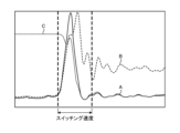
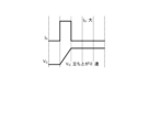
- FIG. 2 shows an example of turn-on Joule loss, turn-on current, and turn-on voltage when the switching speeds of switching elements 311a to 311f of inverter 310 are slowed down in power converter 1 of air conditioner 2 according to Embodiment 1.
- FIG. 3 shows an example of turn-on Joule loss, turn-on current, and turn-on voltage when the switching speed of switching elements 311a to 311f of inverter 310 is increased in power converter 1 of air conditioner 2 according to Embodiment 1.
- A indicates turn-on Joule loss
- B indicates turn-on current
- C indicates turn-on voltage.
- the horizontal axis indicates time.
- the turn-on current is the current flowing through the switching element 311a
- the turn-on voltage is the voltage applied across the switching element 311a
- the turn-on Joule loss is the product of the turn-on current and the turn-on voltage
- the measurement target is the switching element 311a. It is not limited to the element 311a, and other switching elements 311b to 311f may be used.
- FIGS. 2 and 3 show the differences in characteristics depending on the switching speed of the switching elements 311a to 311f of the inverter 310, and the specific values of "slow” and "fast” in the switching speed are not particularly important. . As shown in FIGS.
- the waveform shape changing unit 340 is configured by a digital gate driver.
- the switching elements 311a to 311f of the inverter 310 and the waveform shape changing section 340 are configured by a digital gate driver module.
- the power conversion device 1 can change the switching speed of the switching elements 311a to 311f of the inverter 310 by changing the command value of the software without changing the hardware, and the switching elements 311a to 311f It is possible to control noise and loss generated in a desired state.
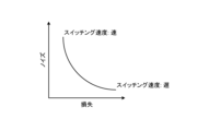
- FIG. 5 is a first diagram showing the effects obtained by changing the switching speeds of the switching elements 311a to 311f of the inverter 310 in the power conversion device 1 of the air conditioner 2 according to the first embodiment.
- the power converter 1 Even if the power converter 1 is operated within the noise range specified by the product in which the power converter 1 is installed, that is, the air conditioner 2, the load state of the motor 314 changes from light load to heavy load. Then, as shown in FIG. 5, the curve representing the characteristics of noise and loss generated in the switching elements 311a to 311f shifts toward the upper right, resulting in an increase in noise. That is, in the power conversion device 1, the heavier the load, the more noise increases. Therefore, the power converter 1 can reduce the noise generated in the switching elements 311a to 311f by slowing down the switching speed of the switching elements 311a to 311f.
- the waveform shape control signal output unit 420 changes the switching elements 311a to 311f so that the noise generated in the switching elements 311a to 311f satisfies the specified requirements. Change the waveform shape of the switching waveform.
- the waveform shape control signal output unit 420 changes the waveform shape of the switching waveform of the switching element 311a so as to suppress loss in the case of light load operation where the operating state is less than the specified load, and changes the waveform shape of the switching waveform of the switching element 311a to suppress the loss.
- the waveform shape of the switching waveform of the switching element 311a is changed so as to suppress noise.
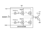
- the waveform shape changing section 340 is connected to the control power supply Vdd and the ground GND.
- the waveform shape changing section 340 changes the number of PMOSs or NMOSs to be operated based on the control signal from the waveform shape control signal output section 420, thereby outputting it to the switching element 311a in each of the turn-on period and the turn-off period.
- the amplitude value of the gate current IG which is the drive signal, can be changed in n ways to adjust the switching speed of the switching element 311a.
- the waveform shape changing unit 340 can increase the absolute value of the gate current IG output to the switching element 311a as the number of PMOSs or NMOSs to be operated increases, and the switching speed of the switching element 311a can be increased. can.
- the waveform shape changing unit 340 can finely adjust the switching speed of the switching element 311a as the number of PMOSs and NMOSs included therein increases, and the faster the response to increase/decrease the gate current IG , the more finely the switching speed of the switching element 311a can be adjusted. It is possible to finely adjust the gate current IG during the switching period.
- the control signal from the waveform shape control signal output section 420 may be an analog signal or a digital signal as long as it can change the number of PMOSs or NMOSs operated by the waveform shape changing section 340. Furthermore, although the example in FIG.
- control signals 7 shows that there are m control signals in parallel from the waveform shape control signal output section 420 to the waveform shape change section 340, this is just an example, and the number of control signals is m. Not limited. The number of control signals may be a number that can indicate whether each PMOS and each NMOS can operate, or it may be one as long as it is an analog signal that indicates voltage or the like.
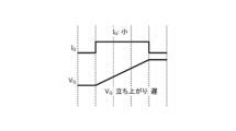
- FIG. 10 shows the relationship between the gate current IG output by the waveform shape changing unit 340 and the gate voltage VG indicating the rising speed of the switching element 311a in the power conversion device 1 included in the air conditioner 2 according to the first embodiment.
- the waveform shape changing unit 340 can divide the turn-on period and change the magnitude of the gate current IG in each period. That is, the waveform shape changing section 340 can finely adjust the magnitude of the gate current IG during one turn-on period.
- the power converter 1 can reduce the noise generated in the switching element 311a while reducing the noise generated in the switching element 311a, as shown in FIG. 6, compared to the case where the same gate current IG is output during the turn-on period. control can be performed to reduce the loss caused by
- FIG. 11 shows an example of the relationship between the basic pulse outputted by the basic pulse generation unit 410 and the gate current IG outputted by the waveform shape changing unit 340 in the power conversion device 1 included in the air conditioner 2 according to the first embodiment. It is a diagram. In FIG. 11, it is assumed that
- the waveform shape changing section 340 changes the waveform shape of the switching waveform of the switching element 311a between the turn-on period and the turn-off period of the switching element 311a based on the control signal output from the waveform shape control signal output section 420. At least one period can be divided into two or more periods, and the amplitude of the gate current IG to the switching element 311a can be changed to a different magnitude in each divided period. Further, the waveform shape changing section 340 includes a plurality of transistors, and changes the amplitude of the gate current IG by changing the number of transistors to be operated based on the control signal output from the waveform shape control signal output section 420. can do. Thereby, the air conditioner 2 can change the noise and loss generated in the switching element 311a according to the operating state.
- the waveform shape changing section 340 can change the output pattern of the gate current IG every switching period of the switching element 311a.
- the waveform shape changing unit 340 can change the switching waveform to a different waveform shape every switching period of the switching element 311a while the power conversion device 1 is in operation.
- the waveform shape changing unit 340 changes the waveform shape of the switching waveform of the switching element 311a while at least one of the motors 314 included in the air conditioner 2, such as a compressor motor and a fan motor, is rotating.
- the waveform shape control signal output section 420 can change the waveform shape of the switching waveform of the switching element 311a at the same cycle as the switching cycle of the switching element 311a.
- the waveform shape control signal output unit 420 may change the waveform shape of the switching waveform of the switching element 311a at a cycle that is a positive integer multiple of the switching cycle of the switching element 311a.
- the waveform shape control signal output section 420 generates switching waveforms of the switching elements 311a to 311f of the inverter 310 based on the basic pulses obtained from the basic pulse generation section 410 and the operating states obtained from the operating state detection sections 501 to 505. Set the waveform shape to change the shape. In this way, in the control section 400, the waveform shape control signal output section 420 turns on the switching elements 311a to 311f determined by the basic pulse generation section 410 based on the operating state acquired from the operating state detection sections 501 to 505. Set the waveform shape of the switching waveform at the turn-off timing and turn-off timing.
- the waveform shape control signal output section 420 outputs a control signal that can change the magnitude and output timing of the drive signal according to the set waveform shape to the waveform shape change section 340 (step S2).
- the processor 91 is a CPU (Central Processing Unit, also referred to as a central processing unit, a processing unit, an arithmetic unit, a microprocessor, a microcomputer, a processor, a DSP (Digital Signal Processor)), or a system LSI (Large Scale Intel). gration).
- the memory 92 includes RAM (Random Access Memory), ROM (Read Only Memory), flash memory, EPROM (Erasable Programmable Read Only Memory), and EEP. Non-volatile or volatile memory such as ROM (registered trademark) (Electrically Erasable Programmable Read Only Memory) An example is semiconductor memory.
- the memory 92 is not limited to these, and may be a magnetic disk, an optical disk, a compact disk, a mini disk, or a DVD (Digital Versatile Disc).
- the air conditioner 2 can control the generation of noise and loss according to the operating state. Furthermore, the air conditioner 2 can change the switching speed of the switching elements 311a to 311f while suppressing an increase in circuit scale.
- the air conditioner 2 finely adjusts the gate current IG or the gate voltage VG output to the switching elements 311a to 311f in one switching period, so that the switching element 311a, which could not be realized with the method of Patent Document 1, etc. It is possible to realize a switching waveform shape of ⁇ 311f.
- Embodiment 2 In the first embodiment, a case has been described in which the waveform shape of the switching waveform of the switching elements 311a to 311f of the inverter 310 is changed in the power conversion device 1 of the air conditioner 2. In Embodiment 2, a case will be described in which the waveform shape of the switching waveform of the switching element 136 of the converter 130 is changed in the power conversion device 1 of the air conditioner 2.
- FIG. 14 is a diagram showing a configuration example of the air conditioner 2 according to the second embodiment.
- Air conditioner 2 includes power converter 1 and motor 314.
- Power conversion device 1 is connected to commercial power source 110 and motor 314.
- the power conversion device 1 converts the first AC power of the power supply voltage Vs supplied from the commercial power supply 110 into second AC power having a desired amplitude and phase, and supplies the second AC power to the motor 314.
- the power converter 1 includes an operating state detecting section 501, a converter 130, a capacitor 210, an operating state detecting section 502, an inverter 310, an operating state detecting section 503, an operating state detecting section 504, and an operating state detecting section 505 and a control unit 400.
- the power converter 1 of the second embodiment shown in FIG. 14 is different from the power converter 1 of the first embodiment shown in FIG. , the drive circuit 150 is removed from the converter 130 and a waveform shape changing section 140 is added. Moreover, the power converter 1 of the second embodiment shown in FIG. 14 is different from the power converter 1 of the first embodiment shown in FIG. is being changed. Specifically, basic pulse generation section 410 outputs a basic pulse for controlling the operation of switching element 136 of converter 130 to waveform shape control signal output section 420, and controls the operation of switching elements 311a to 311f of inverter 310. A basic pulse for control is output to the inverter 310. Further, the waveform shape control signal output section 420 outputs a control signal for controlling the operation of the waveform shape modification section 140 to the waveform shape modification section 140.
- the drive circuit 350 In the inverter 310, the drive circuit 350 generates drive signals for actually driving the switching elements 311a to 311f based on the basic pulses generated by the basic pulse generation unit 410 of the control unit 400.
- waveform shape control signal output section 420 changes the switching waveform of switching element 136 in waveform shape changing section 140 of converter 130 according to the operating state detected by operating state detecting sections 501 to 505.
- the waveform shape of the switching waveform of the switching element 136 at that time is set, and a control signal indicating the set waveform shape is output.
- waveform shape control signal output unit 420 The waveform shape changing unit 140 of 130 controls the magnitude of the drive signal output to the switching element 136 and the timing of outputting the drive signal in order to actually drive the switching element 136.
- Waveform shape control signal output section 420 outputs a control signal for controlling the operation of waveform shape modification section 140 to waveform shape modification section 140 .
- the waveform shape changing unit 140 can change the waveform shape of the switching waveform of the switching element 136.
- the waveform shape changing section 140 can output two or more waveform shapes as the waveform shape of the switching waveform of the switching element 136.
- the waveform shape changing section 140 is included in the converter 130, which is a power converter including a switching element 136, as shown in FIG.
- the configuration of waveform shape changing section 140 is similar to the configuration of waveform shape changing section 340 of Embodiment 1 shown in FIG. That is, the waveform shape changing section 140 and the switching element 136 are configured by one digital gate driver module. Further, like the waveform shape changing unit 340, the waveform shape changing unit 140 may adjust the gate voltage VG output to the switching element 136 instead of the gate current IG outputting to the switching element 136 as a drive signal. .
- the waveform shape changing section 140 changes the waveform shape of the switching waveform of the switching element 136 between the turn-on period and the turn-off period of the switching element 136 based on the control signal output from the waveform shape control signal output section 420. At least one period can be divided into two or more periods, and the amplitude of the gate current IG or gate voltage VG applied to the switching element 136 can be changed to a different magnitude in each divided period.
- the waveform shape changing section 140 includes a plurality of transistors, and changes the number of transistors to be operated based on the control signal output from the waveform shape control signal output section 420, thereby increasing the gate current IG or the gate voltage V. The amplitude of G can be changed.
- power conversion device 1 performs the same operation as in the first embodiment to change the waveform shape of the switching waveform of switching element 136 of converter 130 using waveform shape control signal output section 420 and waveform shape modification section 140. Can be changed. Furthermore, the air conditioner 2 can change the noise and loss generated in the switching element 136 depending on the operating state.
- the waveform shape control signal output section 420 of the control section 400 outputs the output signal of the operation detected by the operation state detection sections 501 to 505.
- the waveform shape changing section 140 of the converter 130 outputs a control signal for changing the switching waveform of the switching element 136.
- the waveform shape changing unit 140 of the converter 130 changes the gate current IG or gate voltage VG output to the switching element 136 based on the control signal output from the waveform shape control signal output unit 420.
- the waveform shape of the switching waveform of 136 is changed.
- the waveform shape changing section 140 can change the waveform shape of the switching waveform of the switching element 136 in the same way that the waveform shape changing section 340 of the first embodiment changes the waveform shape of the switching waveform of the switching element 311a. can.
- the air conditioner 2 can control the generation of noise and loss according to the operating state.
- the air conditioner 2 can change the switching speed of the switching element 136 while suppressing an increase in circuit scale.
- the air conditioner 2 finely adjusts the gate current IG or gate voltage VG output to the switching element 136 during one switching period, thereby achieving switching of the switching element 136 that could not be achieved with the method disclosed in Patent Document 1.
- a waveform shape of a waveform can be realized.
- FIG. 15 is a first diagram showing a rectifying portion of converter 130 included in power conversion device 1 of air conditioner 2 according to the second embodiment.
- FIG. 16 is a second diagram showing the rectifying portion of the converter 130 included in the power conversion device 1 of the air conditioner 2 according to the second embodiment.
- FIG. 17 is a third diagram showing the rectifying part of the converter 130 included in the power conversion device 1 of the air conditioner 2 according to the second embodiment. 15 to 17, only the differences from FIG. 14 are shown, and the description of the waveform shape changing unit 140 is omitted. As shown in FIG.
- the waveform shape changing section 140 changes the waveform shape of the switching waveform of the switching elements 136a to 136d. May be changed.
- the waveform shape changing unit 140 in a configuration in which the converter 130 includes a reactor 135, rectifying elements 131 to 134, a switching element 136, a freewheeling diode 137, and rectifying elements 131a to 134a, the waveform shape changing unit 140 The waveform shape of the switching waveform of 136 may be changed. Further, as shown in FIG.
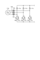
- the connected commercial power source is a three-phase AC power source 110a
- the converter 130 includes reactors 135a to 135c, rectifying elements 131a to 131c, switching elements 136a to 136c, and
- the waveform shape changing section 140 may change the waveform shape of the switching waveforms of the switching elements 136a to 136c.
- Embodiment 3 In the first embodiment, a case has been described in which the waveform shape of the switching waveform of the switching elements 311a to 311f of the inverter 310 is changed in the power conversion device 1 of the air conditioner 2. In the second embodiment, a case has been described in which the waveform shape of the switching waveform of the switching element 136 of the converter 130 is changed in the power conversion device 1 of the air conditioner 2. In the third embodiment, in the power conversion device 1 of the air conditioner 2, the waveform shape of the switching waveform of the switching elements 311a to 311f of the inverter 310 is changed, and the waveform shape of the switching waveform of the switching element 136 of the converter 130 is changed. Let me explain the case.
- a power conversion device 1 according to the third embodiment shown in FIG. 18 is different from the power conversion device 1 according to the first embodiment shown in FIG. It is something. Moreover, the power converter 1 of the third embodiment shown in FIG. 18 is different from the power converter 1 of the first embodiment shown in FIG. is being changed. Specifically, basic pulse generation section 410 outputs a basic pulse for controlling the operation of switching elements 311a to 311f of inverter 310 to waveform shape control signal output section 420, and controls the operation of switching element 136 of converter 130. A basic pulse for control is output to the waveform shape control signal output section 420.
- the waveform shape control signal output section 420 outputs a control signal for controlling the operation of the waveform shape changing section 340 to the waveform shape changing section 340, and outputs a control signal for controlling the operation of the waveform shape changing section 140. It is output to the waveform shape changing section 140.
- the waveform shape control signal output section 420 performs the operation described in the first embodiment as well as the operation described in the second embodiment. Further, in this embodiment, waveform shape changing section 340 performs the same operation as described in Embodiment 1, and waveform shape changing section 140 performs the same operation as described in Embodiment 2. conduct. Thereby, by performing the same operation as in the first embodiment, the power converter 1 changes the waveforms of the switching waveforms of the switching elements 311a to 311f of the inverter 310 by the waveform shape control signal output section 420 and the waveform shape changing section 340. Can change shape. Furthermore, by performing the same operation as in the second embodiment, power converter 1 changes the waveform shape of the switching waveform of switching element 136 of converter 130 using waveform shape control signal output section 420 and waveform shape changing section 140. can do.
- one of the waveform shape changing units 140 and 340 changes the waveform shape of the switching waveform of the switching element at a certain timing, and the other changes the waveform shape of the switching waveform of the switching element. It is also possible to perform control that does not change the shape.
- the switching elements whose switching waveforms are changed by the waveform shape changing units 140 and 340 of the power converter 1 are among the one or more power converters that perform power conversion in the power converter 1.
- the waveform shape of the switching waveform of the switching elements 311a to 311f is changed.
- the waveform shape changing section 140 of the converter 130 changes the gate current IG or gate voltage VG output to the switching element 136 based on the control signal output from the waveform shape control signal output section 420.
- the waveform shape of the switching waveform of the switching element 136 is changed.
- the air conditioner 2 can control the generation of noise and loss according to the operating state.
- the air conditioner 2 can change the switching speeds of the switching elements 311a to 311f and the switching element 136 while suppressing an increase in circuit scale.
- the power conversion device 1 can detect the current flowing through each part, the voltage applied to each part, etc. with respect to the load state, based on the current value, for example, the detected value of the operating state detection sections 501 to 505.
- the power converter 1 can detect the temperature based on a detected value of a temperature sensor (not shown) of an indoor unit included in the air conditioner 2, a detected value of a temperature sensor (not shown) of an outdoor unit, etc., regarding the load state. I can do it.
- the power conversion device 1 may include a temperature sensor around the board of the inverter 310 to detect the temperature around the board of the inverter 310, or may include a temperature sensor around the motor 314 to detect the temperature around the motor 314. may be detected.
- a heating low temperature condition which is an operation mode in an environment where the outside temperature is lower than the heating rated condition.
- the heating low temperature condition has a larger load than the heating rated condition, and the power consumption is even higher.
- the waveform shape control signal output unit 420 performs light load operation when the operating state of the air conditioner 2 is the cooling intermediate condition and heating intermediate condition, and when the operating state of the air conditioner 2 is the cooling rated condition and the heating rated condition. conditions, and other air temperature conditions, heavy load operation shall be performed.
- the waveform shape control signal output unit 420 performs light load operation when the difference between the outside temperature and the set temperature of the air conditioner 2 is less than a specified threshold value, and controls the difference between the outside temperature and the set temperature of the air conditioner 2. If the difference is greater than or equal to a specified threshold, heavy load operation may be performed.
- Embodiment 5 A case will be described in which an adaptive observer is applied as sensorless control of the motor 314 in the power conversion device 1 of Embodiment 1 to Embodiment 4. Specifically, the power conversion device 1 of Embodiment 1 will be explained as an example.
- the speed estimating device 101 includes a model deviation calculation unit 11 that calculates a model deviation ⁇ based on a voltage vector, a current vector, and an estimated angular velocity ⁇ r , and a first and a first angular velocity estimation unit 21 that calculates the estimated angular velocity ⁇ r1 .
- the speed estimating device 101 also includes a second angular velocity estimator 22 that calculates a second estimated angular velocity ⁇ r2 as a high frequency component of the actual angular velocity based on a specific high frequency component included in the model deviation ⁇ , and a first estimated angular velocity and an adder 23 that calculates the estimated angular velocity ⁇ r by adding the second estimated angular velocity ⁇ r2 to the angular velocity ⁇ r1 .
- the velocity estimating device 101 is characterized in that it includes a second angular velocity estimating section 22. The speed estimation device 101 feeds back the sum of the first estimated angular velocity ⁇ r1 and the second estimated angular velocity ⁇ r2 to the model deviation calculation unit 11 as the estimated angular velocity ⁇ r .
- the model deviation calculation unit 11 includes a current estimator 12 that calculates and outputs an estimated magnetic flux vector and an estimated current vector based on the voltage vector, current vector, and estimated angular velocity ⁇ r of the motor 314, and a current estimator 12 that calculates and outputs an estimated magnetic flux vector and an estimated current vector, and a current vector that calculates a current vector from the estimated current vector.
- a subtracter 13 that calculates and outputs a current deviation vector; and a deviation calculator 14 that receives the current deviation vector, extracts the orthogonal component of the estimated magnetic flux vector as a scalar quantity, and outputs this value as a model deviation ⁇ . , is provided.
- the current estimator 12 estimates the current and magnetic flux from the state equation of the motor 314.
- the motor 314 is a general embedded magnet type synchronous AC motor, but even if the motor 314 is other than an embedded magnet type synchronous AC motor, the current estimator 12 can be used in the same manner as long as the state equation can be formulated.
- the current can be estimated using the following method. Examples of the motor 314 other than the embedded magnet type synchronous AC motor include a surface magnet type synchronous motor, an induction motor, and the like. Further, in this embodiment, a rotary motor will be described, but the same technique can also be applied to a direct drive motor. The reason is that a direct-acting motor can be interpreted as a rotary motor with an infinite rotor radius.
- FIG. 21 is a diagram showing a configuration example of an air conditioner 2 according to the sixth embodiment.
- Air conditioner 2 includes power converter 1 and motor 314.
- the configuration of the power converter 1 according to the sixth embodiment shown in FIG. 21 is the same as the power converter 1 according to the first embodiment shown in FIG.
- Converter 130 is a rectifier that has a bridge circuit configured by rectifying elements 131 to 134, and rectifies first AC power of power supply voltage Vs supplied from commercial power supply 110 and outputs the rectifier.
- control unit 400 outputs second AC power including pulsations corresponding to the pulsations of power flowing into capacitor 210 from converter 130, which is a rectifier, from inverter 310 to motor 314, which is a load.
- the operation of the inverter 310 is controlled accordingly.
- the pulsation corresponding to the pulsation of the power flowing into the capacitor 210 is a pulsation that varies depending on the frequency of the pulsation of the power flowing into the capacitor 210, for example.
- the control unit 400 suppresses the current flowing through the capacitor 210.
- the control unit 400 does not need to use all of the detection values obtained from each detection unit, and may perform control using some of the detection values.
- the load generated by the inverter 310 and the motor 314 can be considered as a constant load, and when viewed from the current output from the capacitor 210, the capacitor 210 has a constant current load.
- the current flowing from converter 130 is defined as current I1
- the current flowing through inverter 310 is defined as current I2
- the current flowing from capacitor 210 is defined as current I3.
- the current I2 is a combination of the current I1 and the current I3.
- Current I3 can be expressed as the difference between current I2 and current I1, ie, current I2-current I1.
- the current I3 has a positive direction in which the capacitor 210 is discharged, and a negative direction in which the capacitor 210 is charged. That is, current may flow into the capacitor 210, and current may flow out of the capacitor 210.
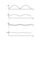
- FIG. 22 shows, as a comparative example, an example of each of the currents I1 to I3 and the capacitor voltage Vdc of the capacitor 210 when the current output from the converter 130 is smoothed by the capacitor 210 and the current I2 flowing to the inverter 310 is kept constant.
- It is a diagram. From the top, current I1, current I2, current I3, and capacitor voltage Vdc of capacitor 210 generated in response to current I3 are shown.
- the vertical axes of currents I1, I2, and I3 indicate current values, and the vertical axis of capacitor voltage Vdc indicates voltage values. All horizontal axes indicate time t. Note that the carrier components of the inverter 310 are actually superimposed on the currents I2 and I3, but this is omitted here.
- the control unit 400 detects the pulsation in accordance with the operating state detected by the operating state detecting units 501 to 505 from the inverter 310, which is a power converter, to the motor 314 connected to the inverter 310.
- the operation of the inverter 310 is controlled so as to be superimposed on the drive pattern, and the charging/discharging current of the capacitor 210 is suppressed.
- the air conditioner 2 can suppress deterioration of the smoothing capacitor 210.
- FIG. 24 is a diagram showing a configuration example of the air conditioner 2 according to the seventh embodiment.
- Air conditioner 2 includes power converter 1 and motor 314.
- the power conversion device 1 according to the seventh embodiment shown in FIG. 24 differs from the power conversion device 1 according to the first embodiment shown in FIG. 30 has been added.
- the rectifier 170 includes a rectifier circuit including four rectifier elements 131 to 134, and a capacitor 210 that is connected between the output terminals of the rectifier circuit and smoothes the voltage of the full-wave rectified waveform output from the rectifier circuit. be done.
- the rectifier 170 rectifies and outputs the first AC power supplied from the commercial power source 110.
- the shorting section 30 short-circuits the commercial power supply 110 via the reactor 135.
- the shorting section 30 includes a diode bridge 31 connected in parallel to the commercial power supply 110 via a reactor 135, and a shorting element 32 connected to both output ends of the diode bridge 31.
- the shorting element 32 is a metal oxide semiconductor field effect transistor
- the gate of the shorting element 32 is connected to the control section 400, and the shorting element 32 is turned on and off by a drive signal from the control section 400.
- the shorting element 32 is turned on, the commercial power supply 110 is short-circuited via the reactor 135 and the diode bridge 31.
- the control unit 400 controls the short circuit operation of the short circuit unit 30.
- the control unit 400 controls the on/off of the short circuit element 32 by current open loop control in the short circuit operation mode so that the short circuit unit 30 is short circuited at least twice or more during a half cycle of the power supply.
- the control unit 400 short-circuits the short circuit unit 30 at least twice during a half cycle of the commercial power supply 110 based on the load condition.
- the air conditioner 2 can suppress fluctuations in the DC voltage even when changing the number of switching times of the shorting section 30 that shorts the commercial power source 110 in accordance with the load condition.
- FIG. 25 is a diagram showing a configuration example of an air conditioner 900 according to Embodiment 8.
- Air conditioner 900 according to Embodiment 8 is provided to explain in more detail the configuration of air conditioner 2 described in Embodiment 1.
- the air conditioner 900 according to the eighth embodiment may be the air conditioner 2 described in the second to seventh embodiments. Note that in FIG. 25, components having the same functions as in the first embodiment are given the same reference numerals as in the first embodiment.
- a compressor 315 incorporating the motor 314 in the first embodiment, a four-way valve 902, an indoor heat exchanger 906, an expansion valve 908, and an outdoor heat exchanger 910 are connected via a refrigerant pipe 912. installed.
- a compression mechanism 904 that compresses the refrigerant and a motor 314 that operates the compression mechanism 904 are provided inside the compressor 315.
- the air conditioner 900 can perform heating operation or cooling operation by switching the four-way valve 902.
- the compression mechanism 904 is driven by a variable speed controlled motor 314.
- the refrigerant is pressurized by the compression mechanism 904 and sent out, passing through the four-way valve 902, indoor heat exchanger 906, expansion valve 908, outdoor heat exchanger 910, and four-way valve 902. Returning to the compression mechanism 904.
- the indoor heat exchanger 906 acts as a condenser and releases heat, and the outdoor heat exchanger 910 acts as an evaporator and absorbs heat.
- the outdoor heat exchanger 910 acts as a condenser and releases heat, and the indoor heat exchanger 906 acts as an evaporator and absorbs heat.
- the expansion valve 908 reduces the pressure of the refrigerant and expands it.
- the digital gate driver module configured by the waveform shape changing section 340 and the switching elements 311a to 311f included in the inverter 310 has a high surge voltage when the switching speed is high. Therefore, a lot of electromagnetic noise is generated.
- the air conditioner 900 uses a flammable refrigerant, there is a possibility that the refrigerant will be combusted due to discharge caused by electromagnetic noise when the refrigerant leaks. Therefore, the air conditioner 900 sets the switching speed of the digital gate driver module included in the power conversion device 1 according to the combustibility of the refrigerant used in the air conditioner 900.
- the air conditioner 900 can reduce surge voltage by slowing down the switching speed of the digital gate driver module, and by suppressing the occurrence of discharge caused by electromagnetic noise, even if refrigerant leaks from the air conditioner 900, the surge voltage can be reduced. Burning can be prevented.
- Refrigerants used in the air conditioner 900 include, for example, R1234yf, R1234ze (E), R1243zf, HFO1123, HFO1132 (E), R1132a, CF3I, R290, R463A, R466A, R454A, R454B, and R454C.
- 1 Power conversion device 2,900 Air conditioner, 11 Model deviation calculation unit, 12 Current estimator, 13 Subtractor, 14 Deviation calculation unit, 21 First angular velocity estimation unit, 22 Second angular velocity estimation unit, 23 Addition Vessels, 30 short circuit, 31 diode bridges, 32 short circuit elements, 101 speed estimation devices, 110, 110A commercial power supply, 130 converters, 131-134, 131a, 131b, 131C rectus elements, 135, 135a -135C, 136 , 136a to 136d, 311a to 311f switching element, 137, 137a to 137d, 312a to 312f freewheeling diode, 138 diode, 140, 340 waveform shape changing unit, 150, 350 drive circuit, 170 rectifier, 210 capacitor, 310 Inverter, 314 Motor, 315 Compressor, 400 Control unit, 410 Basic pulse generation unit, 420 Waveform shape control signal output unit, 501 to 505 Operating state detection unit, 902 Four-way valve, 904
Abstract
This air conditioner (2) for performing air conditioning control comprises: one or more switching elements included in at least one power converter among one or more power converters that perform power conversion; a waveform-shape-changing unit that can change the waveform shape of the switching waveform of the switching element; operating state detection units (501-505) that detect the operating state of the air conditioner (2); and a waveform shape control signal output unit (420) that outputs a control signal when changing the switching waveform of the switching element in the waveform-shape-changing unit according to the operating state.
Description
本開示は、空調制御を行う空気調和機に関する。
The present disclosure relates to an air conditioner that performs air conditioning control.
従来、空気調和機に搭載されるインバータ、コンバータなどの電力変換器において、スイッチング素子に異なるゲート抵抗値のゲート抵抗を切り替えて接続することで、スイッチング素子のスイッチング速度を変化させることが行われている。例えば、特許文献1には、複数のスイッチング素子を有するインバータ主回路を備えるインバータ制御装置において、スイッチング素子のゲート駆動波形を変更する際、スイッチング素子に接続するゲート抵抗について、スイッチを用いて異なるゲート抵抗値のゲート抵抗に切り替える技術が開示されている。
Conventionally, in power converters such as inverters and converters installed in air conditioners, the switching speed of the switching element has been changed by switching and connecting gate resistors with different gate resistance values to the switching element. There is. For example, in Patent Document 1, in an inverter control device including an inverter main circuit having a plurality of switching elements, when changing the gate drive waveform of the switching element, the gate resistance connected to the switching element is changed to a different gate using a switch. A technique for switching to a resistive gate resistor is disclosed.
特許文献1に記載のインバータ制御装置は、空気調和機に適用され、スイッチング素子のスイッチング速度を変化させることで、空気調和機の運転状態に応じて発生するノイズおよび損失の両方を考慮した運転をしている。しかしながら、特許文献1に記載のインバータ制御装置は、スイッチング素子のスイッチング速度を変化させるためにゲート抵抗のゲート抵抗値によって切り替えているが、ゲート抵抗値の個数には限りがある。そのため、特許文献1に記載のインバータ制御装置は、空気調和機の運転状態によっては、スイッチング素子のスイッチング速度を最適な条件にできず、ノイズおよび損失の発生を所望の状態に制御できない場合がある、という問題があった。
The inverter control device described in Patent Document 1 is applied to an air conditioner, and by changing the switching speed of a switching element, it is possible to perform an operation that takes into account both noise and loss that occur depending on the operating state of the air conditioner. are doing. However, although the inverter control device described in Patent Document 1 uses the gate resistance value of the gate resistor to change the switching speed of the switching element, the number of gate resistance values is limited. Therefore, depending on the operating state of the air conditioner, the inverter control device described in Patent Document 1 may not be able to set the switching speed of the switching element to the optimal condition, and may not be able to control the generation of noise and loss to the desired state. There was a problem.
本開示は、上記に鑑みてなされたものであって、運転状態に応じてノイズおよび損失の発生を制御可能な空気調和機を得ることを目的とする。
The present disclosure has been made in view of the above, and aims to provide an air conditioner that can control the generation of noise and loss depending on the operating state.
上述した課題を解決し、目的を達成するために、本開示は、空調制御を行う空気調和機である。空気調和機は、電力変換を行う1以上の電力変換器のうち少なくとも1つの電力変換器に含まれる1以上のスイッチング素子と、スイッチング素子のスイッチング波形の波形形状を変更可能な波形形状変更部と、空気調和機の運転状態を検出する運転状態検出部と、運転状態に応じて、波形形状変更部でスイッチング素子のスイッチング波形を変更する際の制御信号を出力する波形形状制御信号出力部と、を備える。
In order to solve the above-mentioned problems and achieve the objectives, the present disclosure is an air conditioner that performs air conditioning control. The air conditioner includes one or more switching elements included in at least one of the one or more power converters that perform power conversion, and a waveform shape changing unit that can change the waveform shape of a switching waveform of the switching element. , an operating state detection section that detects the operating state of the air conditioner, and a waveform shape control signal output section that outputs a control signal when changing the switching waveform of the switching element in the waveform shape changing section according to the operating state; Equipped with
本開示に係る空気調和機は、運転状態に応じてノイズおよび損失の発生を制御できる、という効果を奏する。
The air conditioner according to the present disclosure has the effect of being able to control the generation of noise and loss depending on the operating state.
以下に、本開示の実施の形態に係る空気調和機を図面に基づいて詳細に説明する。
Below, an air conditioner according to an embodiment of the present disclosure will be described in detail based on the drawings.
実施の形態1.
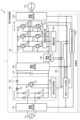
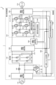
図1は、実施の形態1に係る空気調和機2の構成例を示す図である。空調制御を行う空気調和機2は、電力変換装置1と、モータ314と、を備える。電力変換装置1は、商用電源110およびモータ314に接続される。電力変換装置1は、商用電源110から供給される電源電圧Vsの第1の交流電力を所望の振幅および位相を有する第2の交流電力に電力変換し、モータ314に供給する。商用電源110は、図1の例では単相交流電源であるが、三相交流電源であってもよい。電力変換装置1は、運転状態検出部501と、コンバータ130と、コンデンサ210と、運転状態検出部502と、インバータ310と、運転状態検出部503と、運転状態検出部504と、運転状態検出部505と、制御部400と、を備える。 Embodiment 1.
FIG. 1 is a diagram showing a configuration example of anair conditioner 2 according to the first embodiment. The air conditioner 2 that performs air conditioning control includes a power conversion device 1 and a motor 314. Power conversion device 1 is connected to commercial power source 110 and motor 314. The power conversion device 1 converts the first AC power of the power supply voltage Vs supplied from the commercial power supply 110 into second AC power having a desired amplitude and phase, and supplies the second AC power to the motor 314. Although the commercial power source 110 is a single-phase AC power source in the example of FIG. 1, it may be a three-phase AC power source. The power converter 1 includes an operating state detecting section 501, a converter 130, a capacitor 210, an operating state detecting section 502, an inverter 310, an operating state detecting section 503, an operating state detecting section 504, and an operating state detecting section 505 and a control unit 400.
図1は、実施の形態1に係る空気調和機2の構成例を示す図である。空調制御を行う空気調和機2は、電力変換装置1と、モータ314と、を備える。電力変換装置1は、商用電源110およびモータ314に接続される。電力変換装置1は、商用電源110から供給される電源電圧Vsの第1の交流電力を所望の振幅および位相を有する第2の交流電力に電力変換し、モータ314に供給する。商用電源110は、図1の例では単相交流電源であるが、三相交流電源であってもよい。電力変換装置1は、運転状態検出部501と、コンバータ130と、コンデンサ210と、運転状態検出部502と、インバータ310と、運転状態検出部503と、運転状態検出部504と、運転状態検出部505と、制御部400と、を備える。 Embodiment 1.
FIG. 1 is a diagram showing a configuration example of an
運転状態検出部501は、空気調和機2の運転状態を検出する。運転状態検出部501は、例えば、商用電源110からコンバータ130に供給される電源電圧Vsの交流電力の電圧値、商用電源110からコンバータ130に供給される電源電圧Vsの交流電力の電流値などを検出する。
The operating state detection unit 501 detects the operating state of the air conditioner 2. The operating state detection unit 501 detects, for example, the voltage value of the AC power at the power supply voltage Vs supplied from the commercial power supply 110 to the converter 130, the current value of the AC power at the power supply voltage Vs supplied from the commercial power supply 110 to the converter 130, etc. To detect.
コンバータ130は、商用電源110から供給される電源電圧Vsの交流電力を直流電力に変換する電力変換器である。コンバータ130は、整流素子131~134と、リアクトル135と、スイッチング素子136と、還流ダイオード137と、ダイオード138と、駆動回路150と、を備える。コンバータ130は、整流素子131~134によって構成されるブリッジ回路を有し、商用電源110から供給される電源電圧Vsの第1の交流電力を整流し、整流後の直流電力を昇圧して出力する。駆動回路150は、後述する制御部400の基本パルス生成部410で生成された基本パルスに基づいて、実際にスイッチング素子136を駆動するための駆動信号を生成する。スイッチング素子136は、例えば、IGBT(Insulated Gate Bipolar Transistor)、MOSFET(Metal Oxide Semiconductor Field Effect Transistor)、バイポーラトランジスタなどであるが、これらに限定されない。なお、コンバータ130の構成は、図1の例に限定されない。コンバータ130は、整流素子131~134のうちの1つ以上の整流素子をスイッチング素子で構成してもよい。また、図1に示す実施の形態1の電力変換装置1では、コンバータ130は、整流機能のみを有し、昇圧機能を有していなくてもよい。また、コンバータ130は、商用電源110が三相交流電源の場合、整流素子を6個備える構成となる。
The converter 130 is a power converter that converts AC power of power supply voltage Vs supplied from the commercial power supply 110 into DC power. Converter 130 includes rectifying elements 131 to 134, a reactor 135, a switching element 136, a free wheel diode 137, a diode 138, and a drive circuit 150. The converter 130 has a bridge circuit configured by rectifying elements 131 to 134, rectifies the first AC power of the power supply voltage Vs supplied from the commercial power supply 110, and boosts and outputs the rectified DC power. . The drive circuit 150 generates a drive signal for actually driving the switching element 136 based on a basic pulse generated by a basic pulse generation unit 410 of the control unit 400, which will be described later. The switching element 136 is, for example, an IGBT (Insulated Gate Bipolar Transistor) or a MOSFET (Metal Oxide Semiconductor Field Effect Transistor). or), bipolar transistors, etc., but are not limited to these. Note that the configuration of converter 130 is not limited to the example in FIG. 1. In converter 130, one or more of rectifying elements 131 to 134 may be configured with a switching element. Further, in the power conversion device 1 of the first embodiment shown in FIG. 1, the converter 130 may have only a rectification function and may not have a boost function. Further, when the commercial power source 110 is a three-phase AC power source, the converter 130 has a configuration including six rectifying elements.
コンデンサ210は、コンバータ130の出力端に接続され、コンバータ130によって変換された直流電力を平滑化する。コンデンサ210は、例えば、電解コンデンサ、フィルムコンデンサなどである。
Capacitor 210 is connected to the output end of converter 130 and smoothes the DC power converted by converter 130. The capacitor 210 is, for example, an electrolytic capacitor, a film capacitor, or the like.
運転状態検出部502は、空気調和機2の運転状態を検出する。運転状態検出部502は、例えば、コンデンサ210からインバータ310に供給される直流電力の電圧値などを検出する。
The operating state detection unit 502 detects the operating state of the air conditioner 2. The operating state detection unit 502 detects, for example, the voltage value of the DC power supplied from the capacitor 210 to the inverter 310.
インバータ310は、コンデンサ210の両端に接続される電力変換器である。インバータ310は、スイッチング素子311a~311f、および還流ダイオード312a~312fを有する。インバータ310は、制御部400の制御によってスイッチング素子311a~311fをオンオフし、コンバータ130およびコンデンサ210から出力される電力を所望の振幅および位相を有する第2の交流電力に変換、すなわち第2の交流電力を生成して、モータ314に出力する。スイッチング素子311a~311fは、例えば、IGBT、MOSFET、バイポーラトランジスタなどであるが、これらに限定されない。インバータ310の回路構成は、フルブリッジ回路、単相ブリッジ回路、ハーフブリッジ回路など、特に問わない。また、本実施の形態において、インバータ310は、スイッチング素子311a~311fのスイッチング波形の波形形状を変更可能な波形形状変更部340を備える。波形形状変更部340は、スイッチング素子311a~311fのスイッチング波形の波形形状として、2以上の波形形状を出力可能である。図1の例では、波形形状変更部340は、スイッチング素子311a~311fのスイッチング波形の波形形状を変更可能な構成としているが、スイッチング素子311a~311fのうち少なくとも1つのスイッチング素子のスイッチング波形の波形形状を変更可能とする。また、インバータ310は、スイッチング素子311a~311fごとに波形形状変更部340を備える構成であってもよい。波形形状変更部340の詳細な動作については後述する。
The inverter 310 is a power converter connected to both ends of the capacitor 210. Inverter 310 has switching elements 311a to 311f and free wheel diodes 312a to 312f. Inverter 310 turns on and off switching elements 311a to 311f under the control of control unit 400, converts the power output from converter 130 and capacitor 210 into second AC power having a desired amplitude and phase, that is, second AC power. Electric power is generated and output to motor 314. The switching elements 311a to 311f are, for example, IGBTs, MOSFETs, bipolar transistors, etc., but are not limited to these. The circuit configuration of the inverter 310 is not particularly limited, and may be a full bridge circuit, a single-phase bridge circuit, a half bridge circuit, or the like. Furthermore, in this embodiment, the inverter 310 includes a waveform shape changing section 340 that can change the waveform shape of the switching waveforms of the switching elements 311a to 311f. The waveform shape changing section 340 can output two or more waveform shapes as the waveform shapes of the switching waveforms of the switching elements 311a to 311f. In the example of FIG. 1, the waveform shape changing unit 340 is configured to be able to change the waveform shape of the switching waveform of the switching elements 311a to 311f, but the waveform shape of the switching waveform of at least one switching element among the switching elements 311a to 311f is The shape can be changed. Furthermore, the inverter 310 may be configured to include a waveform shape changing section 340 for each of the switching elements 311a to 311f. The detailed operation of the waveform shape changing section 340 will be described later.
運転状態検出部503は、空気調和機2の運転状態を検出する。運転状態検出部503は、例えば、インバータ310から負荷であるモータ314に供給される第2の交流電力の電圧値、インバータ310から負荷であるモータ314に供給される第2の交流電力の電流値などを検出する。運転状態検出部504は、空気調和機2の運転状態を検出する。運転状態検出部504は、例えば、コンデンサ210からインバータ310に供給される直流電力の電流値などを検出する。運転状態検出部505は、空気調和機2の運転状態を検出する。運転状態検出部505は、例えば、スイッチング素子311b,311d,311fに流れる電流などを検出する。
The operating state detection unit 503 detects the operating state of the air conditioner 2. The operating state detection unit 503 detects, for example, the voltage value of the second AC power supplied from the inverter 310 to the motor 314, which is the load, and the current value of the second AC power, which is supplied from the inverter 310 to the motor 314, which is the load. Detect etc. The operating state detection unit 504 detects the operating state of the air conditioner 2. The operating state detection unit 504 detects, for example, the current value of the DC power supplied from the capacitor 210 to the inverter 310. The operating state detection unit 505 detects the operating state of the air conditioner 2. The operating state detection unit 505 detects, for example, current flowing through the switching elements 311b, 311d, and 311f.
制御部400は、運転状態検出部501~505から、運転状態検出部501~505で検出された運転状態を取得し、取得した運転状態に基づいて、コンバータ130およびインバータ310の動作を制御、具体的には、コンバータ130のスイッチング素子136のオンオフを制御し、インバータ310のスイッチング素子311a~311fのオンオフを制御する。制御部400は、基本パルス生成部410と、波形形状制御信号出力部420と、を備える。
Control unit 400 acquires the operating states detected by operating state detecting units 501 to 505 from operating state detecting units 501 to 505, and controls and specifically controls the operations of converter 130 and inverter 310 based on the obtained operating states. Specifically, it controls the on/off of switching element 136 of converter 130, and controls the on/off of switching elements 311a to 311f of inverter 310. The control section 400 includes a basic pulse generation section 410 and a waveform shape control signal output section 420.
基本パルス生成部410は、運転状態検出部501~505で検出された運転状態に応じたデューティ比を有し、コンバータ130のスイッチング素子136の動作を制御するための基本パルスを生成する。また、基本パルス生成部410は、運転状態検出部501~505で検出された運転状態に応じたデューティ比を有し、インバータ310のスイッチング素子311a~311fの動作を制御するための基本パルスを生成する。基本パルスは、例えば、運転状態検出部501~505で検出された運転状態に応じたデューティ比を有するPWM(Pulse Width Modulation)信号である。基本パルス生成部410は、コンバータ130のスイッチング素子136の動作を制御するための基本パルスをコンバータ130に出力し、インバータ310のスイッチング素子311a~311fの動作を制御するための基本パルスを波形形状制御信号出力部420に出力する。
Basic pulse generating section 410 has a duty ratio according to the operating state detected by operating state detecting sections 501 to 505, and generates a basic pulse for controlling the operation of switching element 136 of converter 130. Further, the basic pulse generation unit 410 has a duty ratio according to the operating state detected by the operating state detection units 501 to 505, and generates a basic pulse for controlling the operation of the switching elements 311a to 311f of the inverter 310. do. The basic pulse is, for example, a PWM (Pulse Width Modulation) signal having a duty ratio according to the operating state detected by the operating state detectors 501 to 505. The basic pulse generation unit 410 outputs basic pulses to the converter 130 for controlling the operation of the switching elements 136 of the converter 130, and controls the waveform shape of the basic pulses for controlling the operations of the switching elements 311a to 311f of the inverter 310. It is output to the signal output section 420.
波形形状制御信号出力部420は、運転状態検出部501~505で検出された運転状態に応じて、インバータ310の波形形状変更部340でスイッチング素子311a~311fのスイッチング波形を変更する際のスイッチング素子311a~311fのスイッチング波形の波形形状を設定し、設定した波形形状を示す制御信号を出力する。具体的には、波形形状制御信号出力部420は、基本パルス生成部410で生成されたインバータ310のスイッチング素子311a~311fの動作を制御するための基本パルスに基づいてスイッチング素子311a~311fをオンオフする際、インバータ310の波形形状変更部340が実際にスイッチング素子311a~311fを駆動するためにスイッチング素子311a~311fに出力する駆動信号の大きさ、および駆動信号を出力するタイミングを制御する。波形形状制御信号出力部420は、波形形状変更部340の動作を制御するための制御信号を波形形状変更部340に出力する。制御部400は、インバータ310がスイッチング素子311a~311fごとに波形形状変更部340を備える、すなわち6個の波形形状変更部340を備える場合、波形形状変更部340ごとに波形形状制御信号出力部420を備える、すなわち6個の波形形状制御信号出力部420を備える構成であってもよい。
The waveform shape control signal output section 420 is a switching element used when changing the switching waveforms of the switching elements 311a to 311f in the waveform shape changing section 340 of the inverter 310 according to the operating state detected by the operating state detecting sections 501 to 505. The waveform shapes of the switching waveforms 311a to 311f are set, and a control signal indicating the set waveform shape is output. Specifically, the waveform shape control signal output unit 420 turns on and off the switching elements 311a to 311f based on the basic pulse generated by the basic pulse generation unit 410 for controlling the operation of the switching elements 311a to 311f of the inverter 310. At this time, the waveform shape changing unit 340 of the inverter 310 controls the magnitude of the drive signal output to the switching elements 311a to 311f and the timing of outputting the drive signal in order to actually drive the switching elements 311a to 311f. The waveform shape control signal output section 420 outputs a control signal for controlling the operation of the waveform shape modification section 340 to the waveform shape modification section 340 . When the inverter 310 includes a waveform shape changing section 340 for each of the switching elements 311a to 311f, that is, six waveform shape changing sections 340, the control section 400 controls a waveform shape control signal output section 420 for each waveform shape changing section 340. In other words, the configuration may include six waveform shape control signal output sections 420.
なお、制御部400は、図1の例では、運転状態検出部501~505から、運転状態検出部501~505で検出された運転状態を取得し、取得した運転状態に基づいて、コンバータ130およびインバータ310の動作を制御していたが、これに限定されない。制御部400は、運転状態検出部501~505のうち少なくとも1つの運転状態検出部から取得した運転状態に基づいて、コンバータ130およびインバータ310の動作を制御することが可能である。電力変換装置1において、運転状態検出部501~505は、前述の例では、電力変換装置1の各構成に入力される電圧または電流、電力変換装置1の各構成から出力される電圧または電流などを運転状態として検出していたが、検出対象はこれらに限定されない。また、運転状態検出部501~505の設置位置は図1の例に限定されない。電力変換装置1は、運転状態検出部501~505を図1の通り全て配置する必要は無い。電力変換装置1は、図示されている以外の位置でも運転状態が検出できれば運転状態検出部をどこに備えていてもよい。電力変換装置1は、電力変換装置1、モータ314などで発生するノイズ、電力変換装置1、モータ314などで発生する損失、電力変換装置1、モータ314などが備える各構成の温度などを運転状態とし、これらの運転状態を検出可能な位置に運転状態検出部を備えていてもよい。また、制御部400は、空気調和機2の運転状態として、ユーザなどが使用する図示しないリモートコントローラなどから取得する空気調和機2に対する設定温度、空気調和機2に対する暖房、冷房などの運転モードなどの情報を利用することが可能である。
In addition, in the example of FIG. 1, control unit 400 acquires the operating states detected by operating state detecting units 501 to 505 from operating state detecting units 501 to 505, and controls converter 130 and Although the operation of the inverter 310 is controlled, the present invention is not limited thereto. Control unit 400 can control the operations of converter 130 and inverter 310 based on the operating state acquired from at least one operating state detecting unit among operating state detecting units 501 to 505. In the power conversion device 1, the operating state detection units 501 to 505, in the above-mentioned example, detect the voltage or current input to each component of the power conversion device 1, the voltage or current output from each component of the power conversion device 1, etc. was detected as the operating state, but the detection target is not limited to these. Furthermore, the installation positions of the operating state detection units 501 to 505 are not limited to the example shown in FIG. 1. In the power conversion device 1, it is not necessary to arrange all the operating state detection units 501 to 505 as shown in FIG. The power conversion device 1 may include the operating state detection section anywhere as long as the operating state can be detected at a position other than that shown in the figure. The power converter 1 monitors operating conditions such as noise generated in the power converter 1, motor 314, etc., loss generated in the power converter 1, motor 314, etc., and temperature of each component included in the power converter 1, motor 314, etc. An operating state detection section may be provided at a position where these operating states can be detected. The control unit 400 also determines the operating state of the air conditioner 2, such as a set temperature for the air conditioner 2 obtained from a remote controller (not shown) used by a user or the like, an operating mode such as heating or cooling for the air conditioner 2, etc. It is possible to use the information of
また、制御部400は、基本パルス生成部410および波形形状制御信号出力部420がともに運転状態検出部501~505から取得した運転状態に基づいて動作をしていることから、基本パルス生成部410および波形形状制御信号出力部420の機能をまとめて1つの構成としてもよい。
Furthermore, since both the basic pulse generation unit 410 and the waveform shape control signal output unit 420 operate based on the operating states acquired from the operating state detection units 501 to 505, the control unit 400 operates based on the operating states obtained from the operating state detection units 501 to 505. The functions of the waveform shape control signal output section 420 and the waveform shape control signal output section 420 may be combined into one configuration.
モータ314は、電力変換装置1に接続される負荷である。モータ314は、例えば、圧縮機駆動用の圧縮機モータである。モータ314は、インバータ310から供給される第2の交流電力の振幅および位相に応じて回転し、圧縮動作を行う。例えば、圧縮機が空気調和機2で使用される密閉型圧縮機の場合、圧縮機を駆動するモータ314の負荷トルクは定トルク負荷とみなせる場合が多い。モータ314は、図示しないモータ巻線について、Y結線であってもよいし、Δ結線であってもよいし、Y結線とΔ結線とが切り替え可能な仕様であってもよい。また、電力変換装置1すなわちインバータ310に接続される負荷は、圧縮機駆動用のモータ314に限定されず、空気調和機2で使用されるファンモータなどであってもよい。すなわち、モータ314は、圧縮機モータ、ファンモータなどである。
The motor 314 is a load connected to the power converter 1. The motor 314 is, for example, a compressor motor for driving a compressor. The motor 314 rotates according to the amplitude and phase of the second AC power supplied from the inverter 310, and performs a compression operation. For example, when the compressor is a hermetic compressor used in the air conditioner 2, the load torque of the motor 314 that drives the compressor can often be regarded as a constant torque load. The motor 314 may have a Y-connection, a Δ-connection, or a specification in which the Y-connection and the Δ-connection can be switched for motor windings (not shown). Further, the load connected to the power conversion device 1, that is, the inverter 310 is not limited to the compressor driving motor 314, but may be a fan motor used in the air conditioner 2, or the like. That is, the motor 314 is a compressor motor, a fan motor, or the like.
本実施の形態において、電力変換装置1は、波形形状制御信号出力部420および波形形状変更部340によって、インバータ310のスイッチング素子311a~311fのスイッチング波形の波形形状を変更することができる。具体的には、電力変換装置1は、インバータ310のスイッチング素子311a~311fのスイッチング速度、遅延時間などを変更することができる。
In the present embodiment, the power conversion device 1 can change the waveform shapes of the switching waveforms of the switching elements 311a to 311f of the inverter 310 using the waveform shape control signal output section 420 and the waveform shape changing section 340. Specifically, the power conversion device 1 can change the switching speed, delay time, etc. of the switching elements 311a to 311f of the inverter 310.
図2は、実施の形態1に係る空気調和機2の電力変換装置1においてインバータ310のスイッチング素子311a~311fのスイッチング速度を遅くしたときのターンオンジュール損失、ターンオン電流、およびターンオン電圧の例を示す図である。図3は、実施の形態1に係る空気調和機2の電力変換装置1においてインバータ310のスイッチング素子311a~311fのスイッチング速度を速くしたときのターンオンジュール損失、ターンオン電流、およびターンオン電圧の例を示す図である。図2および図3において、Aはターンオンジュール損失を示し、Bはターンオン電流を示し、Cはターンオン電圧を示している。図2および図3において、横軸は時間を示している。例えば、ターンオン電流はスイッチング素子311aに流れる電流であり、ターンオン電圧はスイッチング素子311aの両端にかかる電圧であり、ターンオンジュール損失はターンオン電流とターンオン電圧とを乗算したものであるが、測定対象はスイッチング素子311aに限定されず、他のスイッチング素子311b~311fでもよい。なお、図2および図3は、インバータ310のスイッチング素子311a~311fのスイッチング速度による各特性の違いを示すものであり、スイッチング速度の「遅い」および「速い」の具体的な数値は特に問わない。図2および図3に示すように、スイッチング速度を遅くすることで、Bのターンオン電流のピーク値で示されるノイズは小さくなるが、Aのターンオンジュール損失の面積で示される損失は大きくなる。また、図2および図3に示すように、スイッチング速度を速くすることで、Bのターンオン電流のピーク値で示されるノイズは大きくなるが、Aのターンオンジュール損失の面積で示される損失は小さくなる。すなわち、スイッチング素子311a~311fにおいて、発生するノイズおよび損失はトレードオフの関係にある。
FIG. 2 shows an example of turn-on Joule loss, turn-on current, and turn-on voltage when the switching speeds of switching elements 311a to 311f of inverter 310 are slowed down in power converter 1 of air conditioner 2 according to Embodiment 1. It is a diagram. FIG. 3 shows an example of turn-on Joule loss, turn-on current, and turn-on voltage when the switching speed of switching elements 311a to 311f of inverter 310 is increased in power converter 1 of air conditioner 2 according to Embodiment 1. It is a diagram. In FIGS. 2 and 3, A indicates turn-on Joule loss, B indicates turn-on current, and C indicates turn-on voltage. In FIGS. 2 and 3, the horizontal axis indicates time. For example, the turn-on current is the current flowing through the switching element 311a, the turn-on voltage is the voltage applied across the switching element 311a, and the turn-on Joule loss is the product of the turn-on current and the turn-on voltage, but the measurement target is the switching element 311a. It is not limited to the element 311a, and other switching elements 311b to 311f may be used. Note that FIGS. 2 and 3 show the differences in characteristics depending on the switching speed of the switching elements 311a to 311f of the inverter 310, and the specific values of "slow" and "fast" in the switching speed are not particularly important. . As shown in FIGS. 2 and 3, by slowing down the switching speed, the noise represented by the peak value of the turn-on current of B becomes smaller, but the loss represented by the area of the turn-on joule loss of A becomes larger. Furthermore, as shown in Figures 2 and 3, by increasing the switching speed, the noise indicated by the peak value of the turn-on current of B increases, but the loss indicated by the area of the turn-on Joule loss of A decreases. . That is, in the switching elements 311a to 311f, there is a trade-off relationship between noise and loss generated.
電力変換装置1では、波形形状変更部340を、デジタルゲートドライバによって構成する。或いは、電力変換装置1では、インバータ310のスイッチング素子311a~311fおよび波形形状変更部340を、デジタルゲートドライバモジュールによって構成する。これにより、電力変換装置1は、ハードウェアを変更することなく、ソフトウェアの指令値を変更することで、インバータ310のスイッチング素子311a~311fのスイッチング速度を変更することができ、スイッチング素子311a~311fで発生するノイズおよび損失を所望の状態に制御することができる。
In the power conversion device 1, the waveform shape changing unit 340 is configured by a digital gate driver. Alternatively, in the power conversion device 1, the switching elements 311a to 311f of the inverter 310 and the waveform shape changing section 340 are configured by a digital gate driver module. Thereby, the power conversion device 1 can change the switching speed of the switching elements 311a to 311f of the inverter 310 by changing the command value of the software without changing the hardware, and the switching elements 311a to 311f It is possible to control noise and loss generated in a desired state.
図4は、一般的なスイッチング素子で発生するノイズおよび損失の関係の例を示す図である。前述のように、スイッチング素子で発生するノイズおよび損失はトレードオフの関係にある。そのため、一般的なスイッチング素子は、図4に示すように、スイッチング速度を速くすることでノイズは大きくなるが損失は小さくなり、スイッチング速度を遅くすることでノイズは小さくなるが損失は大きくなる。
FIG. 4 is a diagram showing an example of the relationship between noise and loss generated in a general switching element. As mentioned above, there is a trade-off relationship between noise and loss generated in switching elements. Therefore, as shown in FIG. 4, in general switching elements, increasing the switching speed increases noise but decreases loss, and decreasing the switching speed decreases noise but increases loss.
図5は、実施の形態1に係る空気調和機2の電力変換装置1においてインバータ310のスイッチング素子311a~311fのスイッチング速度を変更することによって得られる効果を示す第1の図である。電力変換装置1は、電力変換装置1が搭載される製品、すなわち空気調和機2で規定されているノイズの範囲内で運転していても、モータ314の負荷状態が軽負荷から重負荷に変化すると、図5に示すようにスイッチング素子311a~311fで発生するノイズおよび損失の特性を示すカーブは右上の方に推移し、結果的にノイズが増えることになる。すなわち、電力変換装置1では、負荷が重くなるほど、ノイズが増加する。そのため、電力変換装置1は、スイッチング素子311a~311fのスイッチング速度を遅くすることで、スイッチング素子311a~311fで発生するノイズを小さくすることができる。
FIG. 5 is a first diagram showing the effects obtained by changing the switching speeds of the switching elements 311a to 311f of the inverter 310 in the power conversion device 1 of the air conditioner 2 according to the first embodiment. Even if the power converter 1 is operated within the noise range specified by the product in which the power converter 1 is installed, that is, the air conditioner 2, the load state of the motor 314 changes from light load to heavy load. Then, as shown in FIG. 5, the curve representing the characteristics of noise and loss generated in the switching elements 311a to 311f shifts toward the upper right, resulting in an increase in noise. That is, in the power conversion device 1, the heavier the load, the more noise increases. Therefore, the power converter 1 can reduce the noise generated in the switching elements 311a to 311f by slowing down the switching speed of the switching elements 311a to 311f.
モータ314の負荷状態が軽負荷から重負荷に変化した場合、波形形状制御信号出力部420は、スイッチング素子311a~311fで発生するノイズが規定された要件を満たすように、スイッチング素子311a~311fのスイッチング波形の波形形状を変更する。波形形状制御信号出力部420は、運転状態が規定された負荷未満の軽負荷運転の場合、損失を抑制するようにスイッチング素子311aのスイッチング波形の波形形状を変更し、運転状態が規定された負荷以上の重負荷運転の場合、ノイズを抑制するようにスイッチング素子311aのスイッチング波形の波形形状を変更する。
When the load state of the motor 314 changes from a light load to a heavy load, the waveform shape control signal output unit 420 changes the switching elements 311a to 311f so that the noise generated in the switching elements 311a to 311f satisfies the specified requirements. Change the waveform shape of the switching waveform. The waveform shape control signal output unit 420 changes the waveform shape of the switching waveform of the switching element 311a so as to suppress loss in the case of light load operation where the operating state is less than the specified load, and changes the waveform shape of the switching waveform of the switching element 311a to suppress the loss. In the case of the above heavy load operation, the waveform shape of the switching waveform of the switching element 311a is changed so as to suppress noise.
図6は、実施の形態1に係る空気調和機2の電力変換装置1においてインバータ310のスイッチング素子311a~311fのスイッチング速度を変更することによって得られる効果を示す第2の図である。電力変換装置1、具体的には波形形状変更部340は、スイッチング素子311a~311fの1回のスイッチング動作において、例えば、ターンオン期間またはターンオフ期間を2以上の期間に分割し、分割した各期間においてスイッチング素子311a~311fに対するゲート電流またはゲート電圧の振幅を異なる大きさに変更する。電力変換装置1は、図6に示すようにスイッチング素子311a~311fのスイッチング波形を最適化することで、図4に示すような一般的なスイッチング素子では得られなかったスイッチング素子311a~311fで発生するノイズおよび損失の特性を得ることができる。
FIG. 6 is a second diagram showing the effect obtained by changing the switching speeds of the switching elements 311a to 311f of the inverter 310 in the power conversion device 1 of the air conditioner 2 according to the first embodiment. The power conversion device 1, specifically the waveform shape changing unit 340, divides a turn-on period or a turn-off period into two or more periods in one switching operation of the switching elements 311a to 311f, and in each divided period, The amplitudes of the gate currents or gate voltages for the switching elements 311a to 311f are changed to different magnitudes. By optimizing the switching waveforms of the switching elements 311a to 311f as shown in FIG. 6, the power converter 1 can reduce the power generated in the switching elements 311a to 311f, which could not be achieved with general switching elements as shown in FIG. noise and loss characteristics can be obtained.
ここで、波形形状変更部340の構成について説明する。ここでは一例として、説明を簡単にするため、波形形状変更部340が1つのスイッチング素子311aのスイッチング波形の波形形状を変更可能な場合について説明する。図7は、実施の形態1に係る空気調和機2が備える電力変換装置1の波形形状変更部340の構成例を示す図である。図7は、波形形状変更部340およびスイッチング素子311aによって構成される1つのデジタルゲートドライバモジュールの構成例を示す図でもある。波形形状変更部340は、図1に示すように、スイッチング素子311aを含む電力変換器であるインバータ310に含まれる。波形形状変更部340は、ターンオン用としてn個のPチャネル型のMOSFETであるPMOS(P-channel Metal Oxide Semiconductor)、n個のPMOSを動作させるためのn個のPreDriver、ターンオフ用としてn個のNチャネル型のMOSFETであるNMOS(N-channel Metal Oxide Semiconductor)、およびn個のNMOSを動作させるためのn個のPreDriverを備える。
Here, the configuration of the waveform shape changing section 340 will be explained. Here, as an example, in order to simplify the explanation, a case will be described in which the waveform shape changing section 340 can change the waveform shape of the switching waveform of one switching element 311a. FIG. 7 is a diagram illustrating a configuration example of the waveform shape changing unit 340 of the power conversion device 1 included in the air conditioner 2 according to the first embodiment. FIG. 7 is also a diagram showing a configuration example of one digital gate driver module configured by the waveform shape changing section 340 and the switching element 311a. As shown in FIG. 1, the waveform shape changing section 340 is included in the inverter 310, which is a power converter including a switching element 311a. The waveform shape changing unit 340 includes n PMOSs (P-channel Metal Oxide Semiconductor) which are P-channel MOSFETs for turn-on, n PreDrivers for operating the n PMOSs, and n PreDrivers for turn-off. It includes an NMOS (N-channel Metal Oxide Semiconductor) that is an N-channel MOSFET, and n PreDrivers for operating the n NMOS.
波形形状変更部340は、制御電源VddおよびグランドGNDに接続される。波形形状変更部340は、波形形状制御信号出力部420からの制御信号に基づいて動作させるPMOSまたはNMOSの数を変更することで、ターンオン期間およびターンオフ期間の各期間において、スイッチング素子311aに出力する駆動信号であるゲート電流IGの振幅値をn通りに変更し、スイッチング素子311aのスイッチング速度を調整することができる。波形形状変更部340は、動作させるPMOSまたはNMOSの数を多くするほど、スイッチング素子311aに出力するゲート電流IGの絶対値を大きくすることができ、スイッチング素子311aのスイッチング速度を速くすることができる。また、波形形状変更部340は、内部に備えるPMOSおよびNMOSの数が多いほど、より細かなスイッチング素子311aのスイッチング速度の調整が可能になり、ゲート電流IGの増減の応答が速いほど1回のスイッチング期間で細かなゲート電流IGの調整が可能である。波形形状制御信号出力部420からの制御信号については、波形形状変更部340で動作させるPMOSまたはNMOSの数を変更することができればよいので、アナログ信号でもよいし、デジタル信号でもよい。また、図7の例では、波形形状制御信号出力部420から波形形状変更部340への制御信号が並列でm本あることを示しているが、一例であり、制御信号の数はm本に限定されない。制御信号の数は、各PMOSおよび各NMOSの動作の可否を示すことが可能な数であってもよいし、アナログ信号で電圧などを示すものであれば1つにすることも可能である。
The waveform shape changing section 340 is connected to the control power supply Vdd and the ground GND. The waveform shape changing section 340 changes the number of PMOSs or NMOSs to be operated based on the control signal from the waveform shape control signal output section 420, thereby outputting it to the switching element 311a in each of the turn-on period and the turn-off period. The amplitude value of the gate current IG , which is the drive signal, can be changed in n ways to adjust the switching speed of the switching element 311a. The waveform shape changing unit 340 can increase the absolute value of the gate current IG output to the switching element 311a as the number of PMOSs or NMOSs to be operated increases, and the switching speed of the switching element 311a can be increased. can. In addition, the waveform shape changing unit 340 can finely adjust the switching speed of the switching element 311a as the number of PMOSs and NMOSs included therein increases, and the faster the response to increase/decrease the gate current IG , the more finely the switching speed of the switching element 311a can be adjusted. It is possible to finely adjust the gate current IG during the switching period. The control signal from the waveform shape control signal output section 420 may be an analog signal or a digital signal as long as it can change the number of PMOSs or NMOSs operated by the waveform shape changing section 340. Furthermore, although the example in FIG. 7 shows that there are m control signals in parallel from the waveform shape control signal output section 420 to the waveform shape change section 340, this is just an example, and the number of control signals is m. Not limited. The number of control signals may be a number that can indicate whether each PMOS and each NMOS can operate, or it may be one as long as it is an analog signal that indicates voltage or the like.
図8は、実施の形態1に係る空気調和機2が備える電力変換装置1において波形形状変更部340が出力するゲート電流IGおよびスイッチング素子311aの立ち上がりの速度を示すゲート電圧VGの関係を示す第1の図である。図9は、実施の形態1に係る空気調和機2が備える電力変換装置1において波形形状変更部340が出力するゲート電流IGおよびスイッチング素子311aの立ち上がりの速度を示すゲート電圧VGの関係を示す第2の図である。波形形状変更部340は、図8および図9に示すように、出力するゲート電流IGを大きくするほど、ゲート電圧VGの立ち上がりを速くする、すなわちスイッチング素子311aのスイッチング速度を速くすることができる。また、波形形状変更部340は、図8および図9に示すように、出力するゲート電流IGを小さくするほど、ゲート電圧VGの立ち上がりを遅くする、すなわちスイッチング素子311aのスイッチング速度を遅くすることができる。これにより、電力変換装置1は、図5に示すように、スイッチング素子311aで発生するノイズを小さくしたいときは出力するゲート電流IGを小さくしてスイッチング速度を遅くし、スイッチング素子311aで発生する損失を小さくしたいときは出力するゲート電流IGを大きくしてスイッチング速度を速くすることができる。なお、図8および図9に示すゲート電流IGおよびゲート電圧VGの波形は理想的な例であって、図2および図3に示すように、実際には、ゲート電流IGが一定の電流値になるまでには時間が掛かることになる。
FIG. 8 shows the relationship between the gate current IG output by the waveform shape changing unit 340 and the gate voltage VG indicating the rising speed of the switching element 311a in the power converter 1 included in the air conditioner 2 according to the first embodiment. FIG. FIG. 9 shows the relationship between the gate current IG output by the waveform shape changing unit 340 and the gate voltage VG indicating the rising speed of the switching element 311a in the power conversion device 1 included in the air conditioner 2 according to the first embodiment. FIG. As shown in FIGS. 8 and 9, the waveform shape changing unit 340 can increase the rise of the gate voltage VG , that is, increase the switching speed of the switching element 311a, as the output gate current IG increases. can. Further, as shown in FIGS. 8 and 9, the waveform shape changing unit 340 slows down the rise of the gate voltage VG , as the output gate current IG becomes smaller, that is, the switching speed of the switching element 311a becomes slower. be able to. As a result, as shown in FIG. 5, when the power conversion device 1 wants to reduce the noise generated in the switching element 311a, the output gate current IG is decreased to slow the switching speed, and the noise generated in the switching element 311a is reduced. When it is desired to reduce the loss, the output gate current IG can be increased to increase the switching speed. Note that the waveforms of the gate current IG and gate voltage VG shown in FIGS. 8 and 9 are ideal examples, and in reality, as shown in FIGS. 2 and 3, the gate current IG is constant. It will take time to reach the current value.
図10は、実施の形態1に係る空気調和機2が備える電力変換装置1において波形形状変更部340が出力するゲート電流IGおよびスイッチング素子311aの立ち上がりの速度を示すゲート電圧VGの関係を示す第3の図である。波形形状変更部340は、図10に示すように、ターンオン期間を分割し、各期間でゲート電流IGの大きさを変更することができる。すなわち、波形形状変更部340は、1回のターンオン期間において、ゲート電流IGの大きさを細かく調整することができる。これにより、電力変換装置1は、ターンオン期間中同じゲート電流IGを出力する場合と比較して、図6に示すように、スイッチング素子311aで発生するノイズを小さくしつつ、スイッチング素子311aで発生する損失を小さくするような制御を行うことができる。
FIG. 10 shows the relationship between the gate current IG output by the waveform shape changing unit 340 and the gate voltage VG indicating the rising speed of the switching element 311a in the power conversion device 1 included in the air conditioner 2 according to the first embodiment. FIG. As shown in FIG. 10, the waveform shape changing unit 340 can divide the turn-on period and change the magnitude of the gate current IG in each period. That is, the waveform shape changing section 340 can finely adjust the magnitude of the gate current IG during one turn-on period. As a result, the power converter 1 can reduce the noise generated in the switching element 311a while reducing the noise generated in the switching element 311a, as shown in FIG. 6, compared to the case where the same gate current IG is output during the turn-on period. control can be performed to reduce the loss caused by
図8から図10を用いてスイッチング素子311aのターンオン期間を例にして説明したが、スイッチング素子311aのターンオフ期間についても同様である。図11は、実施の形態1に係る空気調和機2が備える電力変換装置1において基本パルス生成部410が出力する基本パルスおよび波形形状変更部340が出力するゲート電流IGの関係の例を示す図である。図11において、|Ig2|>|Ig1|とする。波形形状変更部340は、スイッチング素子311aのターンオン期間においてゲート電流IGを出力する期間を分割し、最初に振幅の大きい電流Ig2のゲート電流IGを出力してから次に振幅の小さい電流Ig1のゲート電流IGを出力してもよいし、最初に振幅の小さい電流Ig1のゲート電流IGを出力してから次に振幅の大きい電流Ig2のゲート電流IGを出力してもよい。同様に、波形形状変更部340は、スイッチング素子311aのターンオフ期間においてゲート電流IGを出力する期間を分割し、最初に振幅の大きい電流-Ig2のゲート電流IGを出力してから次に振幅の小さい電流-Ig1のゲート電流IGを出力してもよいし、最初に振幅の小さい電流-Ig1のゲート電流IGを出力してから次に振幅の大きい電流-Ig2のゲート電流IGを出力してもよい。
Although the turn-on period of the switching element 311a has been described as an example using FIGS. 8 to 10, the same applies to the turn-off period of the switching element 311a. FIG. 11 shows an example of the relationship between the basic pulse outputted by the basic pulse generation unit 410 and the gate current IG outputted by the waveform shape changing unit 340 in the power conversion device 1 included in the air conditioner 2 according to the first embodiment. It is a diagram. In FIG. 11, it is assumed that |Ig2|>|Ig1|. The waveform shape changing unit 340 divides the period in which the gate current IG is output during the turn-on period of the switching element 311a, first outputs the gate current IG with a large amplitude current Ig2, and then outputs the gate current IG with a small amplitude current Ig1. The gate current IG of current Ig1 with a small amplitude may be outputted first, and then the gate current IG of current Ig2 with a large amplitude may be outputted. Similarly, the waveform shape changing unit 340 divides the period in which the gate current IG is output during the turn-off period of the switching element 311a, first outputs the gate current IG with a large amplitude - Ig2, and then outputs the gate current IG with a large amplitude. It is also possible to output the gate current IG with a small current -Ig1, or first output the gate current IG with a small amplitude current -Ig1, and then output the gate current IG with a current -Ig2 with a large amplitude. You can also output it.
このように、波形形状変更部340は、波形形状制御信号出力部420から出力される制御信号に基づいて、スイッチング素子311aのスイッチング波形の波形形状について、スイッチング素子311aのターンオン期間およびターンオフ期間のうち少なくとも1つの期間を2以上に分割し、分割した各期間においてスイッチング素子311aに対するゲート電流IGの振幅を異なる大きさに変更可能である。また、波形形状変更部340は、複数のトランジスタを備え、波形形状制御信号出力部420から出力される制御信号に基づいて動作させるトランジスタの数を変更することで、ゲート電流IGの振幅を変更することができる。これにより、空気調和機2は、スイッチング素子311aで発生するノイズおよび損失を運転状態に応じて変更可能である。
In this way, the waveform shape changing section 340 changes the waveform shape of the switching waveform of the switching element 311a between the turn-on period and the turn-off period of the switching element 311a based on the control signal output from the waveform shape control signal output section 420. At least one period can be divided into two or more periods, and the amplitude of the gate current IG to the switching element 311a can be changed to a different magnitude in each divided period. Further, the waveform shape changing section 340 includes a plurality of transistors, and changes the amplitude of the gate current IG by changing the number of transistors to be operated based on the control signal output from the waveform shape control signal output section 420. can do. Thereby, the air conditioner 2 can change the noise and loss generated in the switching element 311a according to the operating state.
また、波形形状変更部340は、スイッチング素子311aのスイッチング周期ごとにゲート電流IGの出力パターンを変更することができる。波形形状変更部340は、電力変換装置1の動作中において、スイッチング素子311aのスイッチング周期ごとに異なる波形形状のスイッチング波形に変更可能である。例えば、波形形状変更部340は、空気調和機2が備えるモータ314である圧縮機モータ、ファンモータなどのうち少なくとも1つが回転中に、スイッチング素子311aのスイッチング波形の波形形状を変更する。この場合、波形形状制御信号出力部420は、スイッチング素子311aのスイッチング周期と同じ周期で、スイッチング素子311aのスイッチング波形の波形形状を変更することができる。波形形状制御信号出力部420は、スイッチング素子311aのスイッチング周期の正の整数倍の周期で、スイッチング素子311aのスイッチング波形の波形形状を変更してもよい。
Further, the waveform shape changing section 340 can change the output pattern of the gate current IG every switching period of the switching element 311a. The waveform shape changing unit 340 can change the switching waveform to a different waveform shape every switching period of the switching element 311a while the power conversion device 1 is in operation. For example, the waveform shape changing unit 340 changes the waveform shape of the switching waveform of the switching element 311a while at least one of the motors 314 included in the air conditioner 2, such as a compressor motor and a fan motor, is rotating. In this case, the waveform shape control signal output section 420 can change the waveform shape of the switching waveform of the switching element 311a at the same cycle as the switching cycle of the switching element 311a. The waveform shape control signal output unit 420 may change the waveform shape of the switching waveform of the switching element 311a at a cycle that is a positive integer multiple of the switching cycle of the switching element 311a.
なお、波形形状変更部340の構成について、図7に示す波形形状変更部340の構成は一例であって、これに限定されない。このように、波形形状変更部340は、複数のMOS(Metal Oxide Semiconductor)によるデジタル制御によって、特許文献1に記載したようなゲート抵抗を物理的に切り替えるようなアナログ制御の場合と比較して、スイッチング素子311aのスイッチング速度をより細かに調整することができる。また、波形形状変更部340は、内部で使用するトランジスタについて、MOS以外のトランジスタを使用してもよい。
Note that, regarding the configuration of the waveform shape changing unit 340, the configuration of the waveform shape changing unit 340 shown in FIG. 7 is an example, and is not limited thereto. In this way, the waveform shape changing unit 340 uses digital control using a plurality of MOSs (Metal Oxide Semiconductors), compared to analog control in which the gate resistance is physically switched as described in Patent Document 1. The switching speed of the switching element 311a can be adjusted more finely. Furthermore, the waveform shape changing section 340 may use transistors other than MOS as internally used transistors.
また、波形形状変更部340は、上記の例では取得した制御信号に応じて動作させるPMOSまたはNMOSの数を変更し、動作させるPMOSまたはNMOSの数に応じたゲート電流IGをスイッチング素子311aに出力していたが、これに限定されない。波形形状変更部340は、制御信号に応じたゲート電流IGの出力パターンすなわち波形形状を予め記憶しておき、取得した制御信号に応じた出力パターンすなわち波形形状でゲート電流IGを出力してもよい。また、波形形状変更部340は、過去に取得した制御信号および過去に取得した制御信号のときのゲート電流IGの出力パターンすなわち波形形状を記憶しておき、同じ制御信号を取得した際に記憶していた出力パターンすなわち波形形状でゲート電流IGを出力してもよい。波形形状変更部340は、制御信号に応じたゲート電流IGの出力パターンすなわち波形形状を記憶しておくことで、ゲート電流IGを出力する際の処理負荷を低減することができる。
Further, in the above example, the waveform shape changing unit 340 changes the number of PMOSs or NMOSs to be operated according to the acquired control signal, and applies a gate current IG to the switching element 311a according to the number of PMOSs or NMOSs to be operated. However, the output is not limited to this. The waveform shape changing unit 340 stores in advance an output pattern, that is, a waveform shape, of the gate current IG in accordance with the control signal, and outputs the gate current IG in the output pattern, that is, the waveform shape, in accordance with the acquired control signal. Good too. Further, the waveform shape changing unit 340 stores the control signal acquired in the past and the output pattern, that is, the waveform shape, of the gate current IG for the control signal acquired in the past, and stores it when the same control signal is acquired. The gate current IG may be output in the same output pattern, ie, waveform shape. The waveform shape changing unit 340 can reduce the processing load when outputting the gate current IG by storing the output pattern, that is, the waveform shape, of the gate current IG according to the control signal.
また、波形形状変更部340は、図7の例では、スイッチング素子311aに出力する駆動信号としてゲート電流IGを変更することでスイッチング素子311aのスイッチング速度を調整し、スイッチング素子311aのスイッチング波形の波形形状を変更していたがこれに限定されない。波形形状変更部340は、スイッチング素子311aに出力する駆動信号をゲート電圧VGとし、ゲート電圧VGを変更することで、同様にスイッチング素子311aのスイッチング速度を調整し、スイッチング素子311aのスイッチング波形の波形形状を変更することができる。
Further, in the example of FIG. 7, the waveform shape changing unit 340 adjusts the switching speed of the switching element 311a by changing the gate current IG as a drive signal output to the switching element 311a, and changes the switching waveform of the switching element 311a. Although the waveform shape was changed, the present invention is not limited to this. The waveform shape changing unit 340 sets the drive signal output to the switching element 311a to a gate voltage VG , and by changing the gate voltage VG , similarly adjusts the switching speed of the switching element 311a, and changes the switching waveform of the switching element 311a. The waveform shape of can be changed.
このように、波形形状変更部340は、波形形状制御信号出力部420から出力される制御信号に基づいて、スイッチング素子311aのスイッチング波形の波形形状について、スイッチング素子311aのターンオン期間およびターンオフ期間のうち少なくとも1つの期間を2以上に分割し、分割した各期間においてスイッチング素子311aに対するゲート電圧VGの振幅を異なる大きさに変更可能である。また、波形形状変更部340は、複数のトランジスタを備え、波形形状制御信号出力部420から出力される制御信号に基づいて動作させるトランジスタの数を変更することで、ゲート電圧VGの振幅を変更することができる。これにより、空気調和機2は、スイッチング素子311aで発生するノイズおよび損失を運転状態に応じて変更可能である。
In this way, the waveform shape changing section 340 changes the waveform shape of the switching waveform of the switching element 311a between the turn-on period and the turn-off period of the switching element 311a based on the control signal output from the waveform shape control signal output section 420. At least one period can be divided into two or more periods, and the amplitude of the gate voltage V G applied to the switching element 311a can be changed to a different magnitude in each divided period. Further, the waveform shape changing unit 340 includes a plurality of transistors, and changes the amplitude of the gate voltage V G by changing the number of transistors to be operated based on the control signal output from the waveform shape control signal output unit 420. can do. Thereby, the air conditioner 2 can change the noise and loss generated in the switching element 311a according to the operating state.
図12は、実施の形態1に係る空気調和機2が備える電力変換装置1においてスイッチング素子311a~311fのスイッチング波形の波形形状を変更する動作を示すフローチャートである。電力変換装置1において、基本パルス生成部410は、運転状態検出部501~505から取得した運転状態に基づいて、インバータ310のスイッチング素子311a~311fを駆動するための基本パルスを生成する(ステップS1)。このように、制御部400において、基本パルス生成部410は、運転状態検出部501~505から取得した運転状態に基づいて、基本パルスを生成し、スイッチング素子311a~311fをターンオンするタイミングおよびターンオフするタイミングを決定する。基本パルス生成部410は、生成した基本パルスを波形形状制御信号出力部420に出力する。
FIG. 12 is a flowchart showing the operation of changing the waveform shapes of the switching waveforms of the switching elements 311a to 311f in the power conversion device 1 included in the air conditioner 2 according to the first embodiment. In the power conversion device 1, the basic pulse generation unit 410 generates basic pulses for driving the switching elements 311a to 311f of the inverter 310 based on the operating state acquired from the operating state detection units 501 to 505 (step S1 ). In this way, in the control unit 400, the basic pulse generation unit 410 generates basic pulses based on the operating states acquired from the operating state detection units 501 to 505, and determines the timing to turn on and turn off the switching elements 311a to 311f. Decide on timing. The basic pulse generation section 410 outputs the generated basic pulse to the waveform shape control signal output section 420.
波形形状制御信号出力部420は、基本パルス生成部410から取得した基本パルス、および運転状態検出部501~505から取得した運転状態に基づいて、インバータ310のスイッチング素子311a~311fのスイッチング波形の波形形状を変更するための波形形状を設定する。このように、制御部400において、波形形状制御信号出力部420は、運転状態検出部501~505から取得した運転状態に基づいて、基本パルス生成部410で決定されたスイッチング素子311a~311fをターンオンするタイミングおよびターンオフするタイミングにおけるスイッチング波形の波形形状を設定する。波形形状制御信号出力部420は、波形形状変更部340に対して、設定した波形形状に応じて駆動信号の大きさおよび出力タイミングを変更可能な制御信号を出力する(ステップS2)。
The waveform shape control signal output section 420 generates switching waveforms of the switching elements 311a to 311f of the inverter 310 based on the basic pulses obtained from the basic pulse generation section 410 and the operating states obtained from the operating state detection sections 501 to 505. Set the waveform shape to change the shape. In this way, in the control section 400, the waveform shape control signal output section 420 turns on the switching elements 311a to 311f determined by the basic pulse generation section 410 based on the operating state acquired from the operating state detection sections 501 to 505. Set the waveform shape of the switching waveform at the turn-off timing and turn-off timing. The waveform shape control signal output section 420 outputs a control signal that can change the magnitude and output timing of the drive signal according to the set waveform shape to the waveform shape change section 340 (step S2).
波形形状変更部340は、インバータ310のスイッチング素子311a~311fに出力するゲート電流IGの波形形状、すなわちスイッチング素子311a~311fのスイッチング波形の波形形状を、波形形状制御信号出力部420から取得した制御信号に基づいて変更する(ステップS3)。波形形状変更部340は、波形形状変更後のゲート電流IGをインバータ310のスイッチング素子311a~311fに出力する。
The waveform shape changing unit 340 acquires the waveform shape of the gate current IG output to the switching elements 311a to 311f of the inverter 310, that is, the waveform shape of the switching waveform of the switching elements 311a to 311f, from the waveform shape control signal output unit 420. It is changed based on the control signal (step S3). The waveform shape changing section 340 outputs the gate current IG after changing the waveform shape to the switching elements 311a to 311f of the inverter 310.
つづいて、電力変換装置1が備える制御部400のハードウェア構成について説明する。図13は、実施の形態1に係る空気調和機2の電力変換装置1が備える制御部400を実現するハードウェア構成の一例を示す図である。制御部400は、プロセッサ91およびメモリ92により実現される。
Next, the hardware configuration of the control unit 400 included in the power conversion device 1 will be described. FIG. 13 is a diagram illustrating an example of a hardware configuration that implements the control unit 400 included in the power conversion device 1 of the air conditioner 2 according to the first embodiment. Control unit 400 is realized by processor 91 and memory 92.
プロセッサ91は、CPU(Central Processing Unit、中央処理装置、処理装置、演算装置、マイクロプロセッサ、マイクロコンピュータ、プロセッサ、DSP(Digital Signal Processor)ともいう)、またはシステムLSI(Large Scale Integration)である。メモリ92は、RAM(Random Access Memory)、ROM(Read Only Memory)、フラッシュメモリー、EPROM(Erasable Programmable Read Only Memory)、EEPROM(登録商標)(Electrically Erasable Programmable Read Only Memory)といった不揮発性または揮発性の半導体メモリを例示できる。またメモリ92は、これらに限定されず、磁気ディスク、光ディスク、コンパクトディスク、ミニディスク、またはDVD(Digital Versatile Disc)でもよい。
The processor 91 is a CPU (Central Processing Unit, also referred to as a central processing unit, a processing unit, an arithmetic unit, a microprocessor, a microcomputer, a processor, a DSP (Digital Signal Processor)), or a system LSI (Large Scale Intel). gration). The memory 92 includes RAM (Random Access Memory), ROM (Read Only Memory), flash memory, EPROM (Erasable Programmable Read Only Memory), and EEP. Non-volatile or volatile memory such as ROM (registered trademark) (Electrically Erasable Programmable Read Only Memory) An example is semiconductor memory. Furthermore, the memory 92 is not limited to these, and may be a magnetic disk, an optical disk, a compact disk, a mini disk, or a DVD (Digital Versatile Disc).
以上説明したように、本実施の形態によれば、空気調和機2の電力変換装置1において、制御部400の波形形状制御信号出力部420は、運転状態検出部501~505で検出された運転状態に応じて、インバータ310の波形形状変更部340でスイッチング素子311a~311fのスイッチング波形を変更する際の制御信号を出力する。インバータ310の波形形状変更部340は、波形形状制御信号出力部420から出力される制御信号に基づいて、スイッチング素子311a~311fに出力するゲート電流IGまたはゲート電圧VGを変更することで、スイッチング素子311a~311fのスイッチング波形の波形形状を変更する。これにより、空気調和機2は、運転状態に応じてノイズおよび損失の発生を制御できる。また、空気調和機2は、回路規模の増大を抑制しつつ、スイッチング素子311a~311fのスイッチング速度を変更することができる。空気調和機2は、1回のスイッチング期間においてスイッチング素子311a~311fに出力するゲート電流IGまたはゲート電圧VGを細かく調整することで、特許文献1などの方式では実現できなかったスイッチング素子311a~311fのスイッチング波形の波形形状を実現することができる。
As explained above, according to the present embodiment, in the power conversion device 1 of the air conditioner 2, the waveform shape control signal output section 420 of the control section 400 outputs the output signal of the operation detected by the operation state detection sections 501 to 505. Depending on the state, the waveform shape changing section 340 of the inverter 310 outputs a control signal for changing the switching waveforms of the switching elements 311a to 311f. The waveform shape changing unit 340 of the inverter 310 changes the gate current I G or gate voltage V G output to the switching elements 311a to 311f based on the control signal output from the waveform shape control signal output unit 420. The waveform shape of the switching waveform of the switching elements 311a to 311f is changed. Thereby, the air conditioner 2 can control the generation of noise and loss according to the operating state. Furthermore, the air conditioner 2 can change the switching speed of the switching elements 311a to 311f while suppressing an increase in circuit scale. The air conditioner 2 finely adjusts the gate current IG or the gate voltage VG output to the switching elements 311a to 311f in one switching period, so that the switching element 311a, which could not be realized with the method of Patent Document 1, etc. It is possible to realize a switching waveform shape of ~311f.
実施の形態2.
実施の形態1では、空気調和機2の電力変換装置1において、インバータ310のスイッチング素子311a~311fのスイッチング波形の波形形状を変更する場合について説明した。実施の形態2では、空気調和機2の電力変換装置1において、コンバータ130のスイッチング素子136のスイッチング波形の波形形状を変更する場合について説明する。Embodiment 2.
In the first embodiment, a case has been described in which the waveform shape of the switching waveform of theswitching elements 311a to 311f of the inverter 310 is changed in the power conversion device 1 of the air conditioner 2. In Embodiment 2, a case will be described in which the waveform shape of the switching waveform of the switching element 136 of the converter 130 is changed in the power conversion device 1 of the air conditioner 2.
実施の形態1では、空気調和機2の電力変換装置1において、インバータ310のスイッチング素子311a~311fのスイッチング波形の波形形状を変更する場合について説明した。実施の形態2では、空気調和機2の電力変換装置1において、コンバータ130のスイッチング素子136のスイッチング波形の波形形状を変更する場合について説明する。
In the first embodiment, a case has been described in which the waveform shape of the switching waveform of the
図14は、実施の形態2に係る空気調和機2の構成例を示す図である。空気調和機2は、電力変換装置1と、モータ314と、を備える。電力変換装置1は、商用電源110およびモータ314に接続される。電力変換装置1は、商用電源110から供給される電源電圧Vsの第1の交流電力を所望の振幅および位相を有する第2の交流電力に変換し、モータ314に供給する。電力変換装置1は、運転状態検出部501と、コンバータ130と、コンデンサ210と、運転状態検出部502と、インバータ310と、運転状態検出部503と、運転状態検出部504と、運転状態検出部505と、制御部400と、を備える。
FIG. 14 is a diagram showing a configuration example of the air conditioner 2 according to the second embodiment. Air conditioner 2 includes power converter 1 and motor 314. Power conversion device 1 is connected to commercial power source 110 and motor 314. The power conversion device 1 converts the first AC power of the power supply voltage Vs supplied from the commercial power supply 110 into second AC power having a desired amplitude and phase, and supplies the second AC power to the motor 314. The power converter 1 includes an operating state detecting section 501, a converter 130, a capacitor 210, an operating state detecting section 502, an inverter 310, an operating state detecting section 503, an operating state detecting section 504, and an operating state detecting section 505 and a control unit 400.
図14に示す実施の形態2の電力変換装置1は、図1に示す実施の形態1の電力変換装置1に対して、インバータ310から波形形状変更部340を削除して駆動回路350を追加し、コンバータ130から駆動回路150を削除して波形形状変更部140を追加したものである。また、図14に示す実施の形態2の電力変換装置1は、図1に示す実施の形態1の電力変換装置1に対して、基本パルス生成部410および波形形状制御信号出力部420の出力先を変更している。具体的には、基本パルス生成部410は、コンバータ130のスイッチング素子136の動作を制御するための基本パルスを波形形状制御信号出力部420に出力し、インバータ310のスイッチング素子311a~311fの動作を制御するための基本パルスをインバータ310に出力する。また、波形形状制御信号出力部420は、波形形状変更部140の動作を制御するための制御信号を波形形状変更部140に出力する。
The power converter 1 of the second embodiment shown in FIG. 14 is different from the power converter 1 of the first embodiment shown in FIG. , the drive circuit 150 is removed from the converter 130 and a waveform shape changing section 140 is added. Moreover, the power converter 1 of the second embodiment shown in FIG. 14 is different from the power converter 1 of the first embodiment shown in FIG. is being changed. Specifically, basic pulse generation section 410 outputs a basic pulse for controlling the operation of switching element 136 of converter 130 to waveform shape control signal output section 420, and controls the operation of switching elements 311a to 311f of inverter 310. A basic pulse for control is output to the inverter 310. Further, the waveform shape control signal output section 420 outputs a control signal for controlling the operation of the waveform shape modification section 140 to the waveform shape modification section 140.
インバータ310において、駆動回路350は、制御部400の基本パルス生成部410で生成された基本パルスに基づいて、実際にスイッチング素子311a~311fを駆動するための駆動信号を生成する。
In the inverter 310, the drive circuit 350 generates drive signals for actually driving the switching elements 311a to 311f based on the basic pulses generated by the basic pulse generation unit 410 of the control unit 400.
本実施の形態において、波形形状制御信号出力部420は、運転状態検出部501~505で検出された運転状態に応じて、コンバータ130の波形形状変更部140でスイッチング素子136のスイッチング波形を変更する際のスイッチング素子136のスイッチング波形の波形形状を設定し、設定した波形形状を示す制御信号を出力する。具体的には、波形形状制御信号出力部420は、基本パルス生成部410で生成されたコンバータ130のスイッチング素子136の動作を制御するための基本パルスに基づいてスイッチング素子136をオンオフする際、コンバータ130の波形形状変更部140が実際にスイッチング素子136を駆動するためにスイッチング素子136に出力する駆動信号の大きさ、および駆動信号を出力するタイミングを制御する。波形形状制御信号出力部420は、波形形状変更部140の動作を制御するための制御信号を波形形状変更部140に出力する。
In this embodiment, waveform shape control signal output section 420 changes the switching waveform of switching element 136 in waveform shape changing section 140 of converter 130 according to the operating state detected by operating state detecting sections 501 to 505. The waveform shape of the switching waveform of the switching element 136 at that time is set, and a control signal indicating the set waveform shape is output. Specifically, when turning on and off switching element 136 based on the basic pulse generated by basic pulse generation unit 410 for controlling the operation of switching element 136 of converter 130, waveform shape control signal output unit 420 The waveform shape changing unit 140 of 130 controls the magnitude of the drive signal output to the switching element 136 and the timing of outputting the drive signal in order to actually drive the switching element 136. Waveform shape control signal output section 420 outputs a control signal for controlling the operation of waveform shape modification section 140 to waveform shape modification section 140 .
波形形状変更部140は、スイッチング素子136のスイッチング波形の波形形状を変更可能である。波形形状変更部140は、スイッチング素子136のスイッチング波形の波形形状として、2以上の波形形状を出力可能である。また、波形形状変更部140は、図14に示すように、スイッチング素子136を含む電力変換器であるコンバータ130に含まれる。波形形状変更部140の構成は、図7に示す実施の形態1の波形形状変更部340の構成と同様である。すなわち、波形形状変更部140およびスイッチング素子136は、1つのデジタルゲートドライバモジュールによって構成される。また、波形形状変更部140は、波形形状変更部340と同様、駆動信号として、スイッチング素子136に出力するゲート電流IGではなく、スイッチング素子136に出力するゲート電圧VGを調整してもよい。
The waveform shape changing unit 140 can change the waveform shape of the switching waveform of the switching element 136. The waveform shape changing section 140 can output two or more waveform shapes as the waveform shape of the switching waveform of the switching element 136. Furthermore, the waveform shape changing section 140 is included in the converter 130, which is a power converter including a switching element 136, as shown in FIG. The configuration of waveform shape changing section 140 is similar to the configuration of waveform shape changing section 340 of Embodiment 1 shown in FIG. That is, the waveform shape changing section 140 and the switching element 136 are configured by one digital gate driver module. Further, like the waveform shape changing unit 340, the waveform shape changing unit 140 may adjust the gate voltage VG output to the switching element 136 instead of the gate current IG outputting to the switching element 136 as a drive signal. .
このように、波形形状変更部140は、波形形状制御信号出力部420から出力される制御信号に基づいて、スイッチング素子136のスイッチング波形の波形形状について、スイッチング素子136のターンオン期間およびターンオフ期間のうち少なくとも1つの期間を2以上に分割し、分割した各期間においてスイッチング素子136に対するゲート電流IGまたはゲート電圧VGの振幅を異なる大きさに変更可能である。また、波形形状変更部140は、複数のトランジスタを備え、波形形状制御信号出力部420から出力される制御信号に基づいて動作させるトランジスタの数を変更することで、ゲート電流IGまたはゲート電圧VGの振幅を変更することができる。これにより、電力変換装置1は、実施の形態1と同様の動作を行うことによって、波形形状制御信号出力部420および波形形状変更部140によって、コンバータ130のスイッチング素子136のスイッチング波形の波形形状を変更することができる。また、空気調和機2は、スイッチング素子136で発生するノイズおよび損失を運転状態に応じて変更可能である。
In this way, the waveform shape changing section 140 changes the waveform shape of the switching waveform of the switching element 136 between the turn-on period and the turn-off period of the switching element 136 based on the control signal output from the waveform shape control signal output section 420. At least one period can be divided into two or more periods, and the amplitude of the gate current IG or gate voltage VG applied to the switching element 136 can be changed to a different magnitude in each divided period. In addition, the waveform shape changing section 140 includes a plurality of transistors, and changes the number of transistors to be operated based on the control signal output from the waveform shape control signal output section 420, thereby increasing the gate current IG or the gate voltage V. The amplitude of G can be changed. As a result, power conversion device 1 performs the same operation as in the first embodiment to change the waveform shape of the switching waveform of switching element 136 of converter 130 using waveform shape control signal output section 420 and waveform shape modification section 140. Can be changed. Furthermore, the air conditioner 2 can change the noise and loss generated in the switching element 136 depending on the operating state.
以上説明したように、本実施の形態によれば、空気調和機2の電力変換装置1において、制御部400の波形形状制御信号出力部420は、運転状態検出部501~505で検出された運転状態に応じて、コンバータ130の波形形状変更部140でスイッチング素子136のスイッチング波形を変更する際の制御信号を出力する。コンバータ130の波形形状変更部140は、波形形状制御信号出力部420から出力される制御信号に基づいて、スイッチング素子136に出力するゲート電流IGまたはゲート電圧VGを変更することで、スイッチング素子136のスイッチング波形の波形形状を変更する。波形形状変更部140は、実施の形態1の波形形状変更部340がスイッチング素子311aのスイッチング波形の波形形状を変更するのと同じように、スイッチング素子136のスイッチング波形の波形形状を変更することができる。これにより、空気調和機2は、運転状態に応じてノイズおよび損失の発生を制御できる。また、空気調和機2は、回路規模の増大を抑制しつつ、スイッチング素子136のスイッチング速度を変更することができる。空気調和機2は、1回のスイッチング期間においてスイッチング素子136に出力するゲート電流IGまたはゲート電圧VGを細かく調整することで、特許文献1などの方式では実現できなかったスイッチング素子136のスイッチング波形の波形形状を実現することができる。
As explained above, according to the present embodiment, in the power conversion device 1 of the air conditioner 2, the waveform shape control signal output section 420 of the control section 400 outputs the output signal of the operation detected by the operation state detection sections 501 to 505. Depending on the state, the waveform shape changing section 140 of the converter 130 outputs a control signal for changing the switching waveform of the switching element 136. The waveform shape changing unit 140 of the converter 130 changes the gate current IG or gate voltage VG output to the switching element 136 based on the control signal output from the waveform shape control signal output unit 420. The waveform shape of the switching waveform of 136 is changed. The waveform shape changing section 140 can change the waveform shape of the switching waveform of the switching element 136 in the same way that the waveform shape changing section 340 of the first embodiment changes the waveform shape of the switching waveform of the switching element 311a. can. Thereby, the air conditioner 2 can control the generation of noise and loss according to the operating state. Furthermore, the air conditioner 2 can change the switching speed of the switching element 136 while suppressing an increase in circuit scale. The air conditioner 2 finely adjusts the gate current IG or gate voltage VG output to the switching element 136 during one switching period, thereby achieving switching of the switching element 136 that could not be achieved with the method disclosed in Patent Document 1. A waveform shape of a waveform can be realized.
なお、本実施の形態において、スイッチング素子の波形形状を変更する対象となるコンバータ130の構成は、図14の例に限定されない。図15は、実施の形態2に係る空気調和機2の電力変換装置1が備えるコンバータ130の整流部分を示す第1の図である。図16は、実施の形態2に係る空気調和機2の電力変換装置1が備えるコンバータ130の整流部分を示す第2の図である。図17は、実施の形態2に係る空気調和機2の電力変換装置1が備えるコンバータ130の整流部分を示す第3の図である。図15から図17では、図14との差異のみを示し、波形形状変更部140の記載を省略している。図15に示すように、コンバータ130が、リアクトル135、スイッチング素子136a~136d、および還流ダイオード137a~137dを備える構成において、波形形状変更部140は、スイッチング素子136a~136dのスイッチング波形の波形形状を変更してもよい。また、図16に示すように、コンバータ130が、リアクトル135、整流素子131~134、スイッチング素子136、還流ダイオード137、および整流素子131a~134aを備える構成において、波形形状変更部140は、スイッチング素子136のスイッチング波形の波形形状を変更してもよい。また、図17に示すように、接続される商用電源が三相交流電源の商用電源110aの場合であり、コンバータ130が、リアクトル135a~135c、整流素子131a~131c、スイッチング素子136a~136c、および還流ダイオード137a~137cを備える構成において、波形形状変更部140は、スイッチング素子136a~136cのスイッチング波形の波形形状を変更してもよい。
Note that in this embodiment, the configuration of converter 130, which is the target of changing the waveform shape of the switching element, is not limited to the example shown in FIG. 14. FIG. 15 is a first diagram showing a rectifying portion of converter 130 included in power conversion device 1 of air conditioner 2 according to the second embodiment. FIG. 16 is a second diagram showing the rectifying portion of the converter 130 included in the power conversion device 1 of the air conditioner 2 according to the second embodiment. FIG. 17 is a third diagram showing the rectifying part of the converter 130 included in the power conversion device 1 of the air conditioner 2 according to the second embodiment. 15 to 17, only the differences from FIG. 14 are shown, and the description of the waveform shape changing unit 140 is omitted. As shown in FIG. 15, in a configuration where the converter 130 includes a reactor 135, switching elements 136a to 136d, and freewheeling diodes 137a to 137d, the waveform shape changing section 140 changes the waveform shape of the switching waveform of the switching elements 136a to 136d. May be changed. Further, as shown in FIG. 16, in a configuration in which the converter 130 includes a reactor 135, rectifying elements 131 to 134, a switching element 136, a freewheeling diode 137, and rectifying elements 131a to 134a, the waveform shape changing unit 140 The waveform shape of the switching waveform of 136 may be changed. Further, as shown in FIG. 17, the connected commercial power source is a three-phase AC power source 110a, and the converter 130 includes reactors 135a to 135c, rectifying elements 131a to 131c, switching elements 136a to 136c, and In the configuration including the freewheeling diodes 137a to 137c, the waveform shape changing section 140 may change the waveform shape of the switching waveforms of the switching elements 136a to 136c.
実施の形態3.
実施の形態1では、空気調和機2の電力変換装置1において、インバータ310のスイッチング素子311a~311fのスイッチング波形の波形形状を変更する場合について説明した。実施の形態2では、空気調和機2の電力変換装置1において、コンバータ130のスイッチング素子136のスイッチング波形の波形形状を変更する場合について説明した。実施の形態3では、空気調和機2の電力変換装置1において、インバータ310のスイッチング素子311a~311fのスイッチング波形の波形形状を変更し、コンバータ130のスイッチング素子136のスイッチング波形の波形形状を変更する場合について説明する。 Embodiment 3.
In the first embodiment, a case has been described in which the waveform shape of the switching waveform of theswitching elements 311a to 311f of the inverter 310 is changed in the power conversion device 1 of the air conditioner 2. In the second embodiment, a case has been described in which the waveform shape of the switching waveform of the switching element 136 of the converter 130 is changed in the power conversion device 1 of the air conditioner 2. In the third embodiment, in the power conversion device 1 of the air conditioner 2, the waveform shape of the switching waveform of the switching elements 311a to 311f of the inverter 310 is changed, and the waveform shape of the switching waveform of the switching element 136 of the converter 130 is changed. Let me explain the case.
実施の形態1では、空気調和機2の電力変換装置1において、インバータ310のスイッチング素子311a~311fのスイッチング波形の波形形状を変更する場合について説明した。実施の形態2では、空気調和機2の電力変換装置1において、コンバータ130のスイッチング素子136のスイッチング波形の波形形状を変更する場合について説明した。実施の形態3では、空気調和機2の電力変換装置1において、インバータ310のスイッチング素子311a~311fのスイッチング波形の波形形状を変更し、コンバータ130のスイッチング素子136のスイッチング波形の波形形状を変更する場合について説明する。 Embodiment 3.
In the first embodiment, a case has been described in which the waveform shape of the switching waveform of the
図18は、実施の形態3に係る空気調和機2の構成例を示す図である。空気調和機2は、電力変換装置1と、モータ314と、を備える。電力変換装置1は、商用電源110およびモータ314に接続される。電力変換装置1は、商用電源110から供給される電源電圧Vsの第1の交流電力を所望の振幅および位相を有する第2の交流電力に変換し、モータ314に供給する。電力変換装置1は、運転状態検出部501と、コンバータ130と、コンデンサ210と、運転状態検出部502と、インバータ310と、運転状態検出部503と、運転状態検出部504と、運転状態検出部505と、制御部400と、を備える。
FIG. 18 is a diagram showing a configuration example of the air conditioner 2 according to the third embodiment. Air conditioner 2 includes power converter 1 and motor 314. Power conversion device 1 is connected to commercial power source 110 and motor 314. The power conversion device 1 converts the first AC power of the power supply voltage Vs supplied from the commercial power supply 110 into second AC power having a desired amplitude and phase, and supplies the second AC power to the motor 314. The power converter 1 includes an operating state detecting section 501, a converter 130, a capacitor 210, an operating state detecting section 502, an inverter 310, an operating state detecting section 503, an operating state detecting section 504, and an operating state detecting section 505 and a control unit 400.
図18に示す実施の形態3の電力変換装置1は、図1に示す実施の形態1の電力変換装置1に対して、コンバータ130から駆動回路150を削除して波形形状変更部140を追加したものである。また、図18に示す実施の形態3の電力変換装置1は、図1に示す実施の形態1の電力変換装置1に対して、基本パルス生成部410および波形形状制御信号出力部420の出力先を変更している。具体的には、基本パルス生成部410は、インバータ310のスイッチング素子311a~311fの動作を制御するための基本パルスを波形形状制御信号出力部420に出力し、コンバータ130のスイッチング素子136の動作を制御するための基本パルスを波形形状制御信号出力部420に出力する。また、波形形状制御信号出力部420は、波形形状変更部340の動作を制御するための制御信号を波形形状変更部340に出力し、波形形状変更部140の動作を制御するための制御信号を波形形状変更部140に出力する。
A power conversion device 1 according to the third embodiment shown in FIG. 18 is different from the power conversion device 1 according to the first embodiment shown in FIG. It is something. Moreover, the power converter 1 of the third embodiment shown in FIG. 18 is different from the power converter 1 of the first embodiment shown in FIG. is being changed. Specifically, basic pulse generation section 410 outputs a basic pulse for controlling the operation of switching elements 311a to 311f of inverter 310 to waveform shape control signal output section 420, and controls the operation of switching element 136 of converter 130. A basic pulse for control is output to the waveform shape control signal output section 420. Further, the waveform shape control signal output section 420 outputs a control signal for controlling the operation of the waveform shape changing section 340 to the waveform shape changing section 340, and outputs a control signal for controlling the operation of the waveform shape changing section 140. It is output to the waveform shape changing section 140.
本実施の形態において、波形形状制御信号出力部420は、実施の形態1で説明した動作とともに、実施の形態2で説明した動作を行う。また、本実施の形態において、波形形状変更部340は、実施の形態1で説明した動作と同様の動作を行い、波形形状変更部140は、実施の形態2で説明した動作と同様の動作を行う。これにより、電力変換装置1は、実施の形態1と同様の動作を行うことによって、波形形状制御信号出力部420および波形形状変更部340によって、インバータ310のスイッチング素子311a~311fのスイッチング波形の波形形状を変更することができる。また、電力変換装置1は、実施の形態2と同様の動作を行うことによって、波形形状制御信号出力部420および波形形状変更部140によって、コンバータ130のスイッチング素子136のスイッチング波形の波形形状を変更することができる。
In this embodiment, the waveform shape control signal output section 420 performs the operation described in the first embodiment as well as the operation described in the second embodiment. Further, in this embodiment, waveform shape changing section 340 performs the same operation as described in Embodiment 1, and waveform shape changing section 140 performs the same operation as described in Embodiment 2. conduct. Thereby, by performing the same operation as in the first embodiment, the power converter 1 changes the waveforms of the switching waveforms of the switching elements 311a to 311f of the inverter 310 by the waveform shape control signal output section 420 and the waveform shape changing section 340. Can change shape. Furthermore, by performing the same operation as in the second embodiment, power converter 1 changes the waveform shape of the switching waveform of switching element 136 of converter 130 using waveform shape control signal output section 420 and waveform shape changing section 140. can do.
なお、本実施の形態において、電力変換装置1は、波形形状変更部140,340のうち、あるタイミングでは一方がスイッチング素子のスイッチング波形の波形形状を変更し、他方がスイッチング素子のスイッチング波形の波形形状を変更しないような制御を行うことも可能である。本実施の形態において、電力変換装置1の波形形状変更部140,340がスイッチング素子のスイッチング波形を変更する対象のスイッチング素子は、電力変換装置1において電力変換を行う1以上の電力変換器のうち少なくとも1つの電力変換器に含まれる1以上のスイッチング素子である。
In the present embodiment, in the power conversion device 1, one of the waveform shape changing units 140 and 340 changes the waveform shape of the switching waveform of the switching element at a certain timing, and the other changes the waveform shape of the switching waveform of the switching element. It is also possible to perform control that does not change the shape. In the present embodiment, the switching elements whose switching waveforms are changed by the waveform shape changing units 140 and 340 of the power converter 1 are among the one or more power converters that perform power conversion in the power converter 1. One or more switching elements included in at least one power converter.
以上説明したように、本実施の形態によれば、空気調和機2の電力変換装置1において、制御部400の波形形状制御信号出力部420は、運転状態検出部501~505で検出された運転状態に応じて、インバータ310の波形形状変更部340でスイッチング素子311a~311fのスイッチング波形を変更する際の制御信号を出力し、コンバータ130の波形形状変更部140でスイッチング素子136のスイッチング波形を変更する際の制御信号を出力する。インバータ310の波形形状変更部340は、波形形状制御信号出力部420から出力される制御信号に基づいて、スイッチング素子311a~311fに出力するゲート電流IGまたはゲート電圧VGを変更することで、スイッチング素子311a~311fのスイッチング波形の波形形状を変更する。また、コンバータ130の波形形状変更部140は、波形形状制御信号出力部420から出力される制御信号に基づいて、スイッチング素子136に出力するゲート電流IGまたはゲート電圧VGを変更することで、スイッチング素子136のスイッチング波形の波形形状を変更する。これにより、空気調和機2は、運転状態に応じてノイズおよび損失の発生を制御できる。また、空気調和機2は、回路規模の増大を抑制しつつ、スイッチング素子311a~311fおよびスイッチング素子136のスイッチング速度を変更することができる。空気調和機2は、1回のスイッチング期間においてスイッチング素子311a~311fおよびスイッチング素子136に出力するゲート電流IGまたはゲート電圧VGを細かく調整することで、特許文献1などの方式では実現できなかったスイッチング素子311a~311fおよびスイッチング素子136のスイッチング波形の波形形状を実現することができる。
As explained above, according to the present embodiment, in the power conversion device 1 of the air conditioner 2, the waveform shape control signal output section 420 of the control section 400 outputs the output signal of the operation detected by the operation state detection sections 501 to 505. Depending on the state, the waveform shape changing section 340 of the inverter 310 outputs a control signal for changing the switching waveforms of the switching elements 311a to 311f, and the waveform shape changing section 140 of the converter 130 changes the switching waveform of the switching element 136. Outputs control signals when The waveform shape changing unit 340 of the inverter 310 changes the gate current I G or gate voltage V G output to the switching elements 311a to 311f based on the control signal output from the waveform shape control signal output unit 420. The waveform shape of the switching waveform of the switching elements 311a to 311f is changed. In addition, the waveform shape changing section 140 of the converter 130 changes the gate current IG or gate voltage VG output to the switching element 136 based on the control signal output from the waveform shape control signal output section 420. The waveform shape of the switching waveform of the switching element 136 is changed. Thereby, the air conditioner 2 can control the generation of noise and loss according to the operating state. Furthermore, the air conditioner 2 can change the switching speeds of the switching elements 311a to 311f and the switching element 136 while suppressing an increase in circuit scale. The air conditioner 2 finely adjusts the gate current IG or the gate voltage VG output to the switching elements 311a to 311f and the switching element 136 in one switching period, which is not possible with the method described in Patent Document 1. The waveform shapes of the switching waveforms of the switching elements 311a to 311f and the switching element 136 can be realized as follows.
実施の形態4.
実施の形態1から実施の形態3において、空気調和機2の電力変換装置1は、空気調和機2に搭載されるモータ314などの負荷状態に応じて、スイッチング素子311a~311f、およびスイッチング素子136のスイッチング波形の波形形状を変更していた。実施の形態4では、電力変換装置1の負荷状態を判定する方法について説明する。以下では、具体的に実施の形態1の電力変換装置1を例にして説明を行う。 Embodiment 4.
In Embodiments 1 to 3, the power converter 1 of theair conditioner 2 switches the switching elements 311a to 311f and the switching element 136 according to the load condition of the motor 314 mounted on the air conditioner 2. The waveform shape of the switching waveform was changed. In Embodiment 4, a method for determining the load state of power converter 1 will be described. Below, the power conversion device 1 of Embodiment 1 will be specifically explained as an example.
実施の形態1から実施の形態3において、空気調和機2の電力変換装置1は、空気調和機2に搭載されるモータ314などの負荷状態に応じて、スイッチング素子311a~311f、およびスイッチング素子136のスイッチング波形の波形形状を変更していた。実施の形態4では、電力変換装置1の負荷状態を判定する方法について説明する。以下では、具体的に実施の形態1の電力変換装置1を例にして説明を行う。 Embodiment 4.
In Embodiments 1 to 3, the power converter 1 of the
空気調和機2の運転状態は、動作状態によって大きく変化する。例えば、空気調和機2が空調制御対象とする室内において、ユーザの設定温度、すなわちユーザの所望温度と現在の室内温度との温度差が大きい場合、空気調和機2に搭載された電力変換装置1の負荷は大きくなる。一方、ユーザの所望温度と現在の室内温度との温度差が小さい場合、空気調和機2に搭載された電力変換装置1の負荷は小さくなる。
The operating state of the air conditioner 2 varies greatly depending on the operating state. For example, if there is a large temperature difference between the user's set temperature, that is, the user's desired temperature, and the current indoor temperature in the room that is subject to air conditioning control by the air conditioner 2, the power converter 1 installed in the air conditioner 2 The load will be large. On the other hand, when the temperature difference between the user's desired temperature and the current indoor temperature is small, the load on the power converter 1 installed in the air conditioner 2 becomes small.
電力変換装置1は、負荷状態について、電流値、例えば、運転状態検出部501~505の検出値によって各部に流れる電流、各部に掛かる電圧などを検出することができる。また、電力変換装置1は、負荷状態について、温度、例えば、空気調和機2が備える室内機の図示しない温度センサの検出値、室外機の図示しない温度センサの検出値などによって温度を検出することができる。なお、電力変換装置1は、インバータ310の基板周辺に温度センサを備えてインバータ310の基板周辺の温度を検出してもよいし、モータ314の周辺に温度センサを備えてモータ314の周辺の温度を検出してもよい。また、電力変換装置1は、負荷状態について、運転速度、例えば、モータ314である圧縮機モータ、ファンモータなどの運転速度を、制御部400の制御の過程で生成される指令値、または制御部400の制御の過程で運転周波数から推定される推定値などから直接的、または間接的に検出することができる。このように、負荷状態は、インバータ310、モータ314などを検出対象とした運転状態を検出する運転状態検出部501~505の検出値、制御部400の制御の過程で生成される指令値、および制御部400の制御の過程で推定される推定値のうち少なくとも1つによって得られる。
The power conversion device 1 can detect the current flowing through each part, the voltage applied to each part, etc. with respect to the load state, based on the current value, for example, the detected value of the operating state detection sections 501 to 505. In addition, the power converter 1 can detect the temperature based on a detected value of a temperature sensor (not shown) of an indoor unit included in the air conditioner 2, a detected value of a temperature sensor (not shown) of an outdoor unit, etc., regarding the load state. I can do it. Note that the power conversion device 1 may include a temperature sensor around the board of the inverter 310 to detect the temperature around the board of the inverter 310, or may include a temperature sensor around the motor 314 to detect the temperature around the motor 314. may be detected. The power converter 1 also determines the operating speed of the compressor motor, fan motor, etc., which is the motor 314, using a command value generated in the process of control by the control unit 400, or the control unit It can be detected directly or indirectly from an estimated value estimated from the operating frequency during the control process of 400. In this way, the load state is determined by the detected values of the operating state detection units 501 to 505 that detect the operating states of the inverter 310, motor 314, etc., the command value generated in the process of control by the control unit 400, and It is obtained by at least one of the estimated values estimated in the process of control by the control unit 400.
また、電力変換装置1は、空気調和機2の運転状態について、空気調和機2の空調条件に応じて判定することも可能である。空気調和機2の空調条件は、例えば、冷房中間条件、冷房定格条件、暖房中間条件、暖房定格条件などがある。
Furthermore, the power conversion device 1 can also determine the operating state of the air conditioner 2 according to the air conditioning conditions of the air conditioner 2. The air conditioning conditions of the air conditioner 2 include, for example, cooling intermediate conditions, cooling rated conditions, heating intermediate conditions, heating rated conditions, and the like.
ユーザ操作によって空気調和機2が冷房動作モードに入った運転開始直後は、室内温度と設定された温度とが離れている状態である。圧縮機などに使用されるモータ314が高速回転で運転し、仕事量が多い状態である。このような状態が冷房定格条件と呼ばれる空調条件を表し、消費電力は高い、すなわち重負荷の状態にある。空気調和機2が冷房定格条件で十分に動作を行った時点では、室内温度と設定された温度とが近くなった状態である。圧縮機などに使用されるモータ314が低速回転に移行して運転し、仕事量が少ない状態となる。このような状態が冷房中間条件と呼ばれる空調条件を表し、消費電力は低い、すなわち低負荷の状態にある。
Immediately after the air conditioner 2 enters the cooling operation mode by the user's operation and starts operating, the indoor temperature and the set temperature are far apart. A motor 314 used for a compressor or the like is operating at high speed and has a large amount of work. Such a state represents an air conditioning condition called a cooling rated condition, and the power consumption is high, that is, the air conditioner is in a heavy load state. When the air conditioner 2 has sufficiently operated under the cooling rated conditions, the room temperature and the set temperature are close to each other. The motor 314 used for the compressor etc. shifts to low speed rotation and operates, resulting in a state where the amount of work is small. Such a state represents an air conditioning condition called an intermediate cooling condition, in which power consumption is low, that is, a low load state.
また、ユーザ操作によって空気調和機2が暖房動作モードに入った運転開始直後は、室内温度と設定された温度とが離れている状態である。圧縮機などに使用されるモータ314が高速回転で運転し、仕事量が多い状態である。このような状態が暖房定格条件と呼ばれる空調条件を表し、消費電力は高い、すなわち重負荷の状態にある。空気調和機2が暖房定格条件で十分に動作を行った時点では、室内温度と設定された温度とが近くなった状態である。圧縮機などに使用されるモータ314が低速回転に移行して運転し、仕事量が少ない状態となる。このような状態が暖房中間条件と呼ばれる空調条件を表し、消費電力は低い、すなわち低負荷の状態にある。なお、空気調和機2の空調条件については、暖房定格条件時よりも外気温が低い環境での動作モードである、暖房低温条件と呼ばれる空調条件が存在する。暖房低温条件は、暖房定格条件よりも負荷が大きく、消費電力はさらに高い状態にある。
Immediately after the air conditioner 2 enters the heating operation mode by the user's operation and starts operating, the indoor temperature and the set temperature are far apart. A motor 314 used for a compressor or the like is operating at high speed and has a large amount of work. Such a state represents an air conditioning condition called a heating rated condition, and the power consumption is high, that is, the condition is a heavy load. When the air conditioner 2 has sufficiently operated under the heating rated conditions, the room temperature and the set temperature are close to each other. The motor 314 used for the compressor etc. shifts to low speed rotation and operates, resulting in a state where the amount of work is small. Such a state represents an air conditioning condition called an intermediate heating condition, and power consumption is low, that is, a low load state. Regarding the air conditioning conditions of the air conditioner 2, there is an air conditioning condition called a heating low temperature condition, which is an operation mode in an environment where the outside temperature is lower than the heating rated condition. The heating low temperature condition has a larger load than the heating rated condition, and the power consumption is even higher.
このように、波形形状制御信号出力部420は、空気調和機2の運転状態が冷房中間条件および暖房中間条件の場合は軽負荷運転とし、空気調和機2の運転状態が冷房定格条件、暖房定格条件、およびその他の空気温度条件の場合は重負荷運転とする。
In this way, the waveform shape control signal output unit 420 performs light load operation when the operating state of the air conditioner 2 is the cooling intermediate condition and heating intermediate condition, and when the operating state of the air conditioner 2 is the cooling rated condition and the heating rated condition. conditions, and other air temperature conditions, heavy load operation shall be performed.
また、波形形状制御信号出力部420は、外気温と空気調和機2の設定温度との差分が規定された閾値未満の場合は軽負荷運転とし、外気温と空気調和機2の設定温度との差分が規定された閾値以上の場合は重負荷運転としてもよい。
Further, the waveform shape control signal output unit 420 performs light load operation when the difference between the outside temperature and the set temperature of the air conditioner 2 is less than a specified threshold value, and controls the difference between the outside temperature and the set temperature of the air conditioner 2. If the difference is greater than or equal to a specified threshold, heavy load operation may be performed.
また、波形形状制御信号出力部420は、電力変換器であるインバータ310から出力される負荷電流および負荷電力のうち少なくとも1つが規定された閾値未満の場合は軽負荷運転とし、インバータ310から出力される負荷電流および負荷電力のうち少なくとも1つが規定された閾値以上の場合は重負荷運転としてもよい。
Furthermore, when at least one of the load current and load power output from the inverter 310, which is a power converter, is less than a specified threshold, the waveform shape control signal output unit 420 performs light load operation, and outputs the output from the inverter 310. If at least one of the load current and load power is equal to or higher than a specified threshold value, heavy load operation may be performed.
また、波形形状制御信号出力部420は、電力変換器であるインバータ310またはコンバータ130に入力される入力電流および入力電力のうち少なくとも1つが規定された閾値未満の場合は軽負荷運転とし、電力変換器であるインバータ310またはコンバータ130に入力される入力電流および入力電力のうち少なくとも1つが規定された閾値以上の場合は重負荷運転とする。
In addition, when at least one of the input current and input power input to the inverter 310 or converter 130, which is a power converter, is less than a specified threshold, the waveform shape control signal output unit 420 performs light load operation, and performs power conversion. If at least one of the input current and input power input to the inverter 310 or converter 130, which is a device, is equal to or higher than a prescribed threshold value, heavy load operation is performed.
実施の形態5.
実施の形態1から実施の形態4の電力変換装置1において、モータ314のセンサレス制御として、適応オブザーバを適用する場合について説明する。具体的に、実施の形態1の電力変換装置1を例にして説明する。 Embodiment 5.
A case will be described in which an adaptive observer is applied as sensorless control of themotor 314 in the power conversion device 1 of Embodiment 1 to Embodiment 4. Specifically, the power conversion device 1 of Embodiment 1 will be explained as an example.
実施の形態1から実施の形態4の電力変換装置1において、モータ314のセンサレス制御として、適応オブザーバを適用する場合について説明する。具体的に、実施の形態1の電力変換装置1を例にして説明する。 Embodiment 5.
A case will be described in which an adaptive observer is applied as sensorless control of the
図19は、実施の形態5に係る空気調和機2の構成例を示す図である。空気調和機2は、電力変換装置1と、モータ314と、を備える。図19に示す実施の形態5の電力変換装置1は、図1に示す実施の形態1の電力変換装置1に対して、速度推定装置101を追加したものである。なお、図19において、電力変換装置1内のコンバータ130、インバータ310、および制御部400については記載を簡潔にしている。図20は、実施の形態5に係る空気調和機2の電力変換装置1が備える速度推定装置101の構成例を示す図である。速度推定装置101は、適応オブザーバの手法により、モータ314に印加される電圧ベクトルと電流ベクトルとを用いて、モータ314の回転速度を推定し、推定角速度ω^rとして出力する。
FIG. 19 is a diagram showing a configuration example of an air conditioner 2 according to the fifth embodiment. Air conditioner 2 includes power converter 1 and motor 314. A power converter 1 according to the fifth embodiment shown in FIG. 19 is obtained by adding a speed estimation device 101 to the power converter 1 according to the first embodiment shown in FIG. Note that in FIG. 19, the description of the converter 130, inverter 310, and control unit 400 in the power converter 1 is simplified. FIG. 20 is a diagram illustrating a configuration example of a speed estimating device 101 included in the power conversion device 1 of the air conditioner 2 according to the fifth embodiment. The speed estimating device 101 estimates the rotational speed of the motor 314 using the voltage vector and current vector applied to the motor 314 using an adaptive observer method, and outputs it as an estimated angular speed ω^ r .
速度推定装置101は、電圧ベクトル、電流ベクトルおよび推定角速度ω^rに基づきモデル偏差εを演算するモデル偏差演算部11と、モデル偏差εに基づき実角速度の直流成分を含む低周波成分として第1の推定角速度ω^r1を演算する第1の角速度推定部21とを備える。また、速度推定装置101は、モデル偏差εに含まれる特定の高周波成分に基づき実角速度の高周波成分として第2の推定角速度ω^r2を演算する第2の角速度推定部22と、第1の推定角速度ω^r1に第2の推定角速度ω^r2を加算することにより推定角速度ω^rを演算する加算器23とを備える。速度推定装置101は、第2の角速度推定部22を備える点に特徴がある。速度推定装置101は、第1の推定角速度ω^r1と第2の推定角速度ω^r2との加算値を推定角速度ω^rとしてモデル偏差演算部11にフィードバックする。
The speed estimating device 101 includes a model deviation calculation unit 11 that calculates a model deviation ε based on a voltage vector, a current vector, and an estimated angular velocity ω^ r , and a first and a first angular velocity estimation unit 21 that calculates the estimated angular velocity ω^ r1 . The speed estimating device 101 also includes a second angular velocity estimator 22 that calculates a second estimated angular velocity ω^ r2 as a high frequency component of the actual angular velocity based on a specific high frequency component included in the model deviation ε, and a first estimated angular velocity and an adder 23 that calculates the estimated angular velocity ω^ r by adding the second estimated angular velocity ω^ r2 to the angular velocity ω^ r1 . The velocity estimating device 101 is characterized in that it includes a second angular velocity estimating section 22. The speed estimation device 101 feeds back the sum of the first estimated angular velocity ω^ r1 and the second estimated angular velocity ω^ r2 to the model deviation calculation unit 11 as the estimated angular velocity ω^ r .
モデル偏差演算部11は、モータ314の電圧ベクトルと電流ベクトルと推定角速度ω^rとに基づき、推定磁束ベクトルおよび推定電流ベクトルを演算し出力する電流推定器12と、推定電流ベクトルから電流ベクトルを減算し、電流偏差ベクトルを演算し出力する減算器13と、電流偏差ベクトルを入力とし、推定磁束ベクトルの直交成分をスカラ量として抽出し、この値をモデル偏差εとして出力する偏差演算器14と、を備える。推定磁束ベクトルの直交成分をスカラ量として抽出する手法としては、電流偏差ベクトルを回転二軸上に座標変換する手法と、電流偏差ベクトルと推定磁束ベクトルとの外積値の大きさを演算する手法とが公知である。
The model deviation calculation unit 11 includes a current estimator 12 that calculates and outputs an estimated magnetic flux vector and an estimated current vector based on the voltage vector, current vector, and estimated angular velocity ω^ r of the motor 314, and a current estimator 12 that calculates and outputs an estimated magnetic flux vector and an estimated current vector, and a current vector that calculates a current vector from the estimated current vector. a subtracter 13 that calculates and outputs a current deviation vector; and a deviation calculator 14 that receives the current deviation vector, extracts the orthogonal component of the estimated magnetic flux vector as a scalar quantity, and outputs this value as a model deviation ε. , is provided. There are two methods to extract the orthogonal component of the estimated magnetic flux vector as a scalar quantity: one is to transform the coordinates of the current deviation vector onto two rotating axes, and the other is to calculate the size of the cross product of the current deviation vector and the estimated magnetic flux vector. is publicly known.
電流推定器12は、モータ314の状態方程式から電流と磁束とを推定する。ここではモータ314は一般的な埋込磁石型同期交流電動機であると仮定するが、埋込磁石型同期交流電動機以外のモータ314であっても、電流推定器12は状態方程式が立式できれば同様の方法で電流推定が可能である。埋込磁石型同期交流電動機以外のモータ314は、表面磁石型同期電動機、誘導電動機などを例示できる。また、本実施の形態では回転型モータに関して説明を行うが、直動型モータにも同様の技術が適用できる。その理由は、「直動型モータは回転子半径が無限大の回転型モータ」として解釈できるためである。
The current estimator 12 estimates the current and magnetic flux from the state equation of the motor 314. Here, it is assumed that the motor 314 is a general embedded magnet type synchronous AC motor, but even if the motor 314 is other than an embedded magnet type synchronous AC motor, the current estimator 12 can be used in the same manner as long as the state equation can be formulated. The current can be estimated using the following method. Examples of the motor 314 other than the embedded magnet type synchronous AC motor include a surface magnet type synchronous motor, an induction motor, and the like. Further, in this embodiment, a rotary motor will be described, but the same technique can also be applied to a direct drive motor. The reason is that a direct-acting motor can be interpreted as a rotary motor with an infinite rotor radius.
このように、空気調和機2は、モータ314のセンサレス制御として、適応オブザーバを適用することができる。
In this way, the air conditioner 2 can apply the adaptive observer as sensorless control of the motor 314.
実施の形態6.
実施の形態1から実施の形態3の電力変換装置1において、平滑用のコンデンサ210の劣化を抑制しつつ、装置の大型化を抑制可能な制御を行う場合について説明する。具体的に、実施の形態1の電力変換装置1を例にして説明する。 Embodiment 6.
In the power conversion device 1 of Embodiment 1 to Embodiment 3, a case will be described in which control is performed to suppress deterioration of smoothingcapacitor 210 and to suppress enlargement of the device. Specifically, the power conversion device 1 of Embodiment 1 will be explained as an example.
実施の形態1から実施の形態3の電力変換装置1において、平滑用のコンデンサ210の劣化を抑制しつつ、装置の大型化を抑制可能な制御を行う場合について説明する。具体的に、実施の形態1の電力変換装置1を例にして説明する。 Embodiment 6.
In the power conversion device 1 of Embodiment 1 to Embodiment 3, a case will be described in which control is performed to suppress deterioration of smoothing
図21は、実施の形態6に係る空気調和機2の構成例を示す図である。空気調和機2は、電力変換装置1と、モータ314と、を備える。図21に示す実施の形態6の電力変換装置1の構成は、図1に示す実施の形態1の電力変換装置1と同様の構成である。コンバータ130は、整流素子131~134によって構成されるブリッジ回路を有し、商用電源110から供給される電源電圧Vsの第1の交流電力を整流して出力する整流部である。
FIG. 21 is a diagram showing a configuration example of an air conditioner 2 according to the sixth embodiment. Air conditioner 2 includes power converter 1 and motor 314. The configuration of the power converter 1 according to the sixth embodiment shown in FIG. 21 is the same as the power converter 1 according to the first embodiment shown in FIG. Converter 130 is a rectifier that has a bridge circuit configured by rectifying elements 131 to 134, and rectifies first AC power of power supply voltage Vs supplied from commercial power supply 110 and outputs the rectifier.
本実施の形態において、制御部400は、整流部であるコンバータ130からコンデンサ210に流入する電力の脈動に応じた脈動を含む第2の交流電力をインバータ310から負荷であるモータ314に出力するようにインバータ310の動作を制御する。コンデンサ210に流入する電力の脈動に応じた脈動とは、例えば、コンデンサ210に流入する電力の脈動の周波数などによって変動する脈動である。これにより、制御部400は、コンデンサ210に流れる電流を抑制する。なお、制御部400は、各検出部から取得した全ての検出値を用いなくてもよく、一部の検出値を用いて制御を行ってもよい。
In the present embodiment, control unit 400 outputs second AC power including pulsations corresponding to the pulsations of power flowing into capacitor 210 from converter 130, which is a rectifier, from inverter 310 to motor 314, which is a load. The operation of the inverter 310 is controlled accordingly. The pulsation corresponding to the pulsation of the power flowing into the capacitor 210 is a pulsation that varies depending on the frequency of the pulsation of the power flowing into the capacitor 210, for example. Thereby, the control unit 400 suppresses the current flowing through the capacitor 210. Note that the control unit 400 does not need to use all of the detection values obtained from each detection unit, and may perform control using some of the detection values.
電力変換装置1が備える制御部400の動作について説明する。本実施の形態では、電力変換装置1において、インバータ310およびモータ314によって発生する負荷が一定の負荷とみなすことができ、コンデンサ210から出力される電流で見た場合、コンデンサ210に定電流負荷が接続されているものとして、以降の説明を行う。ここで、図21に示すように、コンバータ130から流れる電流を電流I1とし、インバータ310に流れる電流を電流I2とし、コンデンサ210から流れる電流を電流I3とする。電流I2は、電流I1と電流I3とを併せた電流となる。電流I3は、電流I2と電流I1との差分、すなわち電流I2-電流I1として表すことができる。電流I3は、コンデンサ210の放電方向を正方向とし、コンデンサ210の充電方向を負方向とする。すなわち、コンデンサ210には、電流が流入することもあり、電流が流出することもある。
The operation of the control unit 400 included in the power conversion device 1 will be described. In this embodiment, in the power converter 1, the load generated by the inverter 310 and the motor 314 can be considered as a constant load, and when viewed from the current output from the capacitor 210, the capacitor 210 has a constant current load. The following explanation will be given assuming that they are connected. Here, as shown in FIG. 21, the current flowing from converter 130 is defined as current I1, the current flowing through inverter 310 is defined as current I2, and the current flowing from capacitor 210 is defined as current I3. The current I2 is a combination of the current I1 and the current I3. Current I3 can be expressed as the difference between current I2 and current I1, ie, current I2-current I1. The current I3 has a positive direction in which the capacitor 210 is discharged, and a negative direction in which the capacitor 210 is charged. That is, current may flow into the capacitor 210, and current may flow out of the capacitor 210.
図22は、比較例として、コンデンサ210でコンバータ130から出力される電流を平滑化し、インバータ310に流れる電流I2を一定にした場合の各電流I1~I3およびコンデンサ210のコンデンサ電圧Vdcの例を示す図である。上から順に、電流I1、電流I2、電流I3、および電流I3に応じて発生するコンデンサ210のコンデンサ電圧Vdcを示している。電流I1,I2,I3の縦軸は電流値を示し、コンデンサ電圧Vdcの縦軸は電圧値を示している。横軸は全て時間tを示している。なお、電流I2,I3には、実際にはインバータ310のキャリア成分が重畳されるが、ここでは省略する。以降についても同様とする。図22に示すように、電力変換装置1において、仮に、コンバータ130から流れる電流I1がコンデンサ210によって十分に平滑化された場合、インバータ310に流れる電流I2は一定の電流値となる。しかしながら、コンデンサ210には、大きな電流I3が流れ、劣化の要因となる。そのため、本実施の形態では、電力変換装置1において、制御部400は、コンデンサ210に流れる電流I3を低減するように、インバータ310に流れる電流I2を制御、すなわちインバータ310の動作を制御する。
FIG. 22 shows, as a comparative example, an example of each of the currents I1 to I3 and the capacitor voltage Vdc of the capacitor 210 when the current output from the converter 130 is smoothed by the capacitor 210 and the current I2 flowing to the inverter 310 is kept constant. It is a diagram. From the top, current I1, current I2, current I3, and capacitor voltage Vdc of capacitor 210 generated in response to current I3 are shown. The vertical axes of currents I1, I2, and I3 indicate current values, and the vertical axis of capacitor voltage Vdc indicates voltage values. All horizontal axes indicate time t. Note that the carrier components of the inverter 310 are actually superimposed on the currents I2 and I3, but this is omitted here. The same shall apply thereafter. As shown in FIG. 22, in power conversion device 1, if current I1 flowing from converter 130 is sufficiently smoothed by capacitor 210, current I2 flowing to inverter 310 has a constant current value. However, a large current I3 flows through the capacitor 210, causing deterioration. Therefore, in the present embodiment, in power conversion device 1, control unit 400 controls current I2 flowing through inverter 310, that is, controls the operation of inverter 310, so as to reduce current I3 flowing through capacitor 210.
図23は、実施の形態6に係る空気調和機2が備える電力変換装置1の制御部400がインバータ310の動作を制御してコンデンサ210に流れる電流I3を低減したときの各電流I1~I3およびコンデンサ210のコンデンサ電圧Vdcの例を示す図である。上から順に、電流I1、電流I2、電流I3、および電流I3に応じて発生するコンデンサ210のコンデンサ電圧Vdcを示している。電流I1,I2,I3の縦軸は電流値を示し、コンデンサ電圧Vdcの縦軸は電圧値を示している。横軸は全て時間tを示している。電力変換装置1の制御部400は、図23に示すような電流I2がインバータ310に流れるようにインバータ310の動作を制御することによって、図22の例と比較して、コンバータ130からコンデンサ210に流れ込む電流の周波数成分を低減し、コンデンサ210に流れる電流I3を低減することができる。具体的には、制御部400は、電流I1の周波数成分を主成分とした脈動電流を含む電流I2がインバータ310に流れるようにインバータ310の動作を制御する。
FIG. 23 illustrates each current I1 to I3 and 5 is a diagram showing an example of capacitor voltage Vdc of capacitor 210. FIG. From the top, current I1, current I2, current I3, and capacitor voltage Vdc of capacitor 210 generated in response to current I3 are shown. The vertical axes of currents I1, I2, and I3 indicate current values, and the vertical axis of capacitor voltage Vdc indicates voltage values. All horizontal axes indicate time t. Control unit 400 of power converter 1 controls the operation of inverter 310 so that current I2 as shown in FIG. It is possible to reduce the frequency component of the current flowing into the capacitor 210, thereby reducing the current I3 flowing into the capacitor 210. Specifically, the control unit 400 controls the operation of the inverter 310 so that a current I2 including a pulsating current whose main component is the frequency component of the current I1 flows through the inverter 310.
このように、電力変換装置1において、制御部400は、運転状態検出部501~505で検出された運転状態に応じた脈動が電力変換器であるインバータ310からインバータ310に接続されるモータ314の駆動パターンに重畳されるようにインバータ310の動作を制御し、コンデンサ210の充放電電流を抑制する。これにより、空気調和機2は、平滑用のコンデンサ210の劣化を抑制することができる。
In this way, in the power converter 1, the control unit 400 detects the pulsation in accordance with the operating state detected by the operating state detecting units 501 to 505 from the inverter 310, which is a power converter, to the motor 314 connected to the inverter 310. The operation of the inverter 310 is controlled so as to be superimposed on the drive pattern, and the charging/discharging current of the capacitor 210 is suppressed. Thereby, the air conditioner 2 can suppress deterioration of the smoothing capacitor 210.
実施の形態7.
実施の形態1から実施の形態3の電力変換装置1において、交流電源である商用電源110を短絡する短絡部のスイッチング回数を負荷条件に対応して変化させる場合でも直流電圧の変動を抑制することが可能な制御を行う場合について説明する。具体的に、実施の形態1の電力変換装置1を例にして説明する。 Embodiment 7.
In the power conversion device 1 of Embodiment 1 to Embodiment 3, it is possible to suppress fluctuations in DC voltage even when changing the number of times of switching of a short-circuit part that short-circuitscommercial power supply 110, which is an AC power supply, in accordance with load conditions. A case will be explained in which control is possible. Specifically, the power conversion device 1 of Embodiment 1 will be explained as an example.
実施の形態1から実施の形態3の電力変換装置1において、交流電源である商用電源110を短絡する短絡部のスイッチング回数を負荷条件に対応して変化させる場合でも直流電圧の変動を抑制することが可能な制御を行う場合について説明する。具体的に、実施の形態1の電力変換装置1を例にして説明する。 Embodiment 7.
In the power conversion device 1 of Embodiment 1 to Embodiment 3, it is possible to suppress fluctuations in DC voltage even when changing the number of times of switching of a short-circuit part that short-circuits
図24は、実施の形態7に係る空気調和機2の構成例を示す図である。空気調和機2は、電力変換装置1と、モータ314と、を備える。図24に示す実施の形態7の電力変換装置1は、図1に示す実施の形態1の電力変換装置1に対して、コンバータ130およびコンデンサ210を削除し、リアクトル135、整流部170、および短絡部30を追加したものである。整流部170は、4つの整流素子131~134で構成された整流回路と、整流回路の出力端間に接続され整流回路から出力される全波整流波形の電圧を平滑化するコンデンサ210とから構成される。整流部170は、商用電源110から供給される第1の交流電力を整流して出力する。
FIG. 24 is a diagram showing a configuration example of the air conditioner 2 according to the seventh embodiment. Air conditioner 2 includes power converter 1 and motor 314. The power conversion device 1 according to the seventh embodiment shown in FIG. 24 differs from the power conversion device 1 according to the first embodiment shown in FIG. 30 has been added. The rectifier 170 includes a rectifier circuit including four rectifier elements 131 to 134, and a capacitor 210 that is connected between the output terminals of the rectifier circuit and smoothes the voltage of the full-wave rectified waveform output from the rectifier circuit. be done. The rectifier 170 rectifies and outputs the first AC power supplied from the commercial power source 110.
短絡部30は、リアクトル135を介して商用電源110を短絡する。短絡部30は、リアクトル135を介して商用電源110に並列に接続されたダイオードブリッジ31と、ダイオードブリッジ31の両出力端に接続された短絡素子32とから構成される。短絡素子32が金属酸化膜半導体電界効果トランジスタである場合、短絡素子32のゲートは制御部400に接続され、制御部400からの駆動信号によって短絡素子32がオンオフする構成である。短絡素子32がオンされたとき、リアクトル135およびダイオードブリッジ31を介して商用電源110が短絡する。
The shorting section 30 short-circuits the commercial power supply 110 via the reactor 135. The shorting section 30 includes a diode bridge 31 connected in parallel to the commercial power supply 110 via a reactor 135, and a shorting element 32 connected to both output ends of the diode bridge 31. When the shorting element 32 is a metal oxide semiconductor field effect transistor, the gate of the shorting element 32 is connected to the control section 400, and the shorting element 32 is turned on and off by a drive signal from the control section 400. When the shorting element 32 is turned on, the commercial power supply 110 is short-circuited via the reactor 135 and the diode bridge 31.
制御部400は、短絡部30の短絡動作を制御する。制御部400は、短絡動作モードの電流オープンループ制御にて、短絡部30を電源半周期中に少なくとも2回以上短絡させるように短絡素子32のオンオフを制御する。制御部400は、負荷条件に基づいて商用電源110の半周期中において短絡部30を少なくとも2回以上短絡させる。これにより、空気調和機2は、商用電源110を短絡する短絡部30のスイッチング回数を負荷条件に対応して変化させる場合でも、直流電圧の変動を抑制することができる。
The control unit 400 controls the short circuit operation of the short circuit unit 30. The control unit 400 controls the on/off of the short circuit element 32 by current open loop control in the short circuit operation mode so that the short circuit unit 30 is short circuited at least twice or more during a half cycle of the power supply. The control unit 400 short-circuits the short circuit unit 30 at least twice during a half cycle of the commercial power supply 110 based on the load condition. Thereby, the air conditioner 2 can suppress fluctuations in the DC voltage even when changing the number of switching times of the shorting section 30 that shorts the commercial power source 110 in accordance with the load condition.
実施の形態8.
図25は、実施の形態8に係る空気調和機900の構成例を示す図である。実施の形態8に係る空気調和機900は、実施の形態1で説明した空気調和機2の構成をより詳細に説明するためのものである。実施の形態8に係る空気調和機900は、実施の形態2から実施の形態7で説明した空気調和機2であってもよい。なお、図25において、実施の形態1と同様の機能を有する構成要素には、実施の形態1と同一の符号を付している。 Embodiment 8.
FIG. 25 is a diagram showing a configuration example of anair conditioner 900 according to Embodiment 8. Air conditioner 900 according to Embodiment 8 is provided to explain in more detail the configuration of air conditioner 2 described in Embodiment 1. The air conditioner 900 according to the eighth embodiment may be the air conditioner 2 described in the second to seventh embodiments. Note that in FIG. 25, components having the same functions as in the first embodiment are given the same reference numerals as in the first embodiment.
図25は、実施の形態8に係る空気調和機900の構成例を示す図である。実施の形態8に係る空気調和機900は、実施の形態1で説明した空気調和機2の構成をより詳細に説明するためのものである。実施の形態8に係る空気調和機900は、実施の形態2から実施の形態7で説明した空気調和機2であってもよい。なお、図25において、実施の形態1と同様の機能を有する構成要素には、実施の形態1と同一の符号を付している。 Embodiment 8.
FIG. 25 is a diagram showing a configuration example of an
空気調和機900は、実施の形態1におけるモータ314を内蔵した圧縮機315と、四方弁902と、室内熱交換器906と、膨張弁908と、室外熱交換器910とが冷媒配管912を介して取り付けられている。
In the air conditioner 900, a compressor 315 incorporating the motor 314 in the first embodiment, a four-way valve 902, an indoor heat exchanger 906, an expansion valve 908, and an outdoor heat exchanger 910 are connected via a refrigerant pipe 912. installed.
圧縮機315の内部には、冷媒を圧縮する圧縮機構904と、圧縮機構904を動作させるモータ314とが設けられている。
A compression mechanism 904 that compresses the refrigerant and a motor 314 that operates the compression mechanism 904 are provided inside the compressor 315.
空気調和機900は、四方弁902の切替動作により暖房運転又は冷房運転をすることができる。圧縮機構904は、可変速制御されるモータ314によって駆動される。
The air conditioner 900 can perform heating operation or cooling operation by switching the four-way valve 902. The compression mechanism 904 is driven by a variable speed controlled motor 314.
暖房運転時には、実線矢印で示すように、冷媒が圧縮機構904で加圧されて送り出され、四方弁902、室内熱交換器906、膨張弁908、室外熱交換器910及び四方弁902を通って圧縮機構904に戻る。
During heating operation, as shown by the solid arrow, the refrigerant is pressurized by the compression mechanism 904 and sent out, passing through the four-way valve 902, indoor heat exchanger 906, expansion valve 908, outdoor heat exchanger 910, and four-way valve 902. Returning to the compression mechanism 904.
冷房運転時には、破線矢印で示すように、冷媒が圧縮機構904で加圧されて送り出され、四方弁902、室外熱交換器910、膨張弁908、室内熱交換器906及び四方弁902を通って圧縮機構904に戻る。
During cooling operation, the refrigerant is pressurized by the compression mechanism 904 and sent out, passing through the four-way valve 902, the outdoor heat exchanger 910, the expansion valve 908, the indoor heat exchanger 906, and the four-way valve 902, as shown by the dashed arrow. Returning to the compression mechanism 904.
暖房運転時には、室内熱交換器906が凝縮器として作用して熱放出を行い、室外熱交換器910が蒸発器として作用して熱吸収を行う。冷房運転時には、室外熱交換器910が凝縮器として作用して熱放出を行い、室内熱交換器906が蒸発器として作用し、熱吸収を行う。膨張弁908は、冷媒を減圧して膨張させる。
During heating operation, the indoor heat exchanger 906 acts as a condenser and releases heat, and the outdoor heat exchanger 910 acts as an evaporator and absorbs heat. During cooling operation, the outdoor heat exchanger 910 acts as a condenser and releases heat, and the indoor heat exchanger 906 acts as an evaporator and absorbs heat. The expansion valve 908 reduces the pressure of the refrigerant and expands it.
ここで、空気調和機900が備える電力変換装置1において、インバータ310に含まれる波形形状変更部340およびスイッチング素子311a~311fによって構成されるデジタルゲートドライバモジュールは、スイッチング速度が速いとサージ電圧が大きくなり、電磁ノイズが多く発生する。空気調和機900は、燃焼性のある冷媒を使用する場合、冷媒が漏れた際に電磁ノイズが起因となる放電によって燃焼する可能性がある。そのため、空気調和機900は、空気調和機900で使用される冷媒の燃焼性に応じて、電力変換装置1が備えるデジタルゲートドライバモジュールのスイッチング速度を設定する。例えば、空気調和機900は、空気調和機900で使用される冷媒の燃焼性が高いほど、電力変換装置1が備えるデジタルゲートドライバモジュールのスイッチング速度を遅くする。空気調和機900は、デジタルゲートドライバモジュールのスイッチング速度を遅くすることでサージ電圧を小さくでき、電磁ノイズが起因となる放電の発生を抑えることで、仮に空気調和機900から冷媒が漏れた場合でも燃焼することを防止することができる。
Here, in the power conversion device 1 included in the air conditioner 900, the digital gate driver module configured by the waveform shape changing section 340 and the switching elements 311a to 311f included in the inverter 310 has a high surge voltage when the switching speed is high. Therefore, a lot of electromagnetic noise is generated. When the air conditioner 900 uses a flammable refrigerant, there is a possibility that the refrigerant will be combusted due to discharge caused by electromagnetic noise when the refrigerant leaks. Therefore, the air conditioner 900 sets the switching speed of the digital gate driver module included in the power conversion device 1 according to the combustibility of the refrigerant used in the air conditioner 900. For example, the higher the flammability of the refrigerant used in the air conditioner 900 is, the slower the switching speed of the digital gate driver module included in the power converter 1 is. The air conditioner 900 can reduce surge voltage by slowing down the switching speed of the digital gate driver module, and by suppressing the occurrence of discharge caused by electromagnetic noise, even if refrigerant leaks from the air conditioner 900, the surge voltage can be reduced. Burning can be prevented.
空気調和機900で使用される冷媒は、例えば、R1234yf、R1234ze(E)、R1243zf、HFO1123、HFO1132(E)、R1132a、CF3I、R290、R463A、R466A、R454A、R454B、R454Cなどである。
Refrigerants used in the air conditioner 900 include, for example, R1234yf, R1234ze (E), R1243zf, HFO1123, HFO1132 (E), R1132a, CF3I, R290, R463A, R466A, R454A, R454B, and R454C.
以上の実施の形態に示した構成は、一例を示すものであり、別の公知の技術と組み合わせることも可能であるし、実施の形態同士を組み合わせることも可能であるし、要旨を逸脱しない範囲で、構成の一部を省略、変更することも可能である。
The configurations shown in the embodiments above are merely examples, and can be combined with other known techniques, or can be combined with other embodiments, within the scope of the gist. It is also possible to omit or change part of the configuration.
1 電力変換装置、2,900 空気調和機、11 モデル偏差演算部、12 電流推定器、13 減算器、14 偏差演算器、21 第1の角速度推定部、22 第2の角速度推定部、23 加算器、30 短絡部、31 ダイオードブリッジ、32 短絡素子、101 速度推定装置、110,110a 商用電源、130 コンバータ、131~134,131a~134a,131b,131c 整流素子、135,135a~135c リアクトル、136,136a~136d,311a~311f スイッチング素子、137,137a~137d,312a~312f 還流ダイオード、138 ダイオード、140,340 波形形状変更部、150,350 駆動回路、170 整流部、210 コンデンサ、310 インバータ、314 モータ、315 圧縮機、400 制御部、410 基本パルス生成部、420 波形形状制御信号出力部、501~505 運転状態検出部、902 四方弁、904 圧縮機構、906 室内熱交換器、908 膨張弁、910 室外熱交換器、912 冷媒配管。
1 Power conversion device, 2,900 Air conditioner, 11 Model deviation calculation unit, 12 Current estimator, 13 Subtractor, 14 Deviation calculation unit, 21 First angular velocity estimation unit, 22 Second angular velocity estimation unit, 23 Addition Vessels, 30 short circuit, 31 diode bridges, 32 short circuit elements, 101 speed estimation devices, 110, 110A commercial power supply, 130 converters, 131-134, 131a, 131b, 131C rectus elements, 135, 135a -135C, 136 , 136a to 136d, 311a to 311f switching element, 137, 137a to 137d, 312a to 312f freewheeling diode, 138 diode, 140, 340 waveform shape changing unit, 150, 350 drive circuit, 170 rectifier, 210 capacitor, 310 Inverter, 314 Motor, 315 Compressor, 400 Control unit, 410 Basic pulse generation unit, 420 Waveform shape control signal output unit, 501 to 505 Operating state detection unit, 902 Four-way valve, 904 Compression mechanism, 906 Indoor heat exchanger, 908 Expansion valve , 910 Outdoor heat exchanger, 912 Refrigerant piping.
Claims (14)
- 空調制御を行う空気調和機であって、
電力変換を行う1以上の電力変換器のうち少なくとも1つの前記電力変換器に含まれる1以上のスイッチング素子と、
前記スイッチング素子のスイッチング波形の波形形状を変更可能な波形形状変更部と、
前記空気調和機の運転状態を検出する運転状態検出部と、
前記運転状態に応じて、前記波形形状変更部で前記スイッチング素子の前記スイッチング波形を変更する際の制御信号を出力する波形形状制御信号出力部と、
を備える空気調和機。 An air conditioner that performs air conditioning control,
one or more switching elements included in at least one of the one or more power converters that perform power conversion;
a waveform shape changing unit capable of changing the waveform shape of the switching waveform of the switching element;
an operating state detection unit that detects an operating state of the air conditioner;
a waveform shape control signal output unit that outputs a control signal when the waveform shape changing unit changes the switching waveform of the switching element according to the operating state;
Air conditioner equipped with. - 前記波形形状変更部は、前記波形形状制御信号出力部から出力される前記制御信号に基づいて、前記スイッチング素子の前記スイッチング波形の波形形状について、前記スイッチング素子のターンオン期間およびターンオフ期間のうち少なくとも1つの期間を2以上に分割し、分割した各期間において前記スイッチング素子に対するゲート電流またはゲート電圧の振幅を異なる大きさに変更することで、前記スイッチング素子で発生するノイズおよび損失を前記運転状態に応じて変更可能である、
請求項1に記載の空気調和機。 The waveform shape changing section changes the waveform shape of the switching waveform of the switching element to at least one of a turn-on period and a turn-off period of the switching element, based on the control signal output from the waveform shape control signal output section. By dividing one period into two or more and changing the amplitude of the gate current or gate voltage to the switching element to a different magnitude in each divided period, the noise and loss generated in the switching element can be reduced according to the operating state. can be changed by
The air conditioner according to claim 1. - 前記波形形状変更部は、前記空気調和機が備える圧縮機モータおよびファンモータのうち少なくとも1つが回転中に、前記スイッチング素子の前記スイッチング波形の波形形状を変更する、
請求項1または2に記載の空気調和機。 The waveform shape changing unit changes the waveform shape of the switching waveform of the switching element while at least one of a compressor motor and a fan motor included in the air conditioner is rotating.
The air conditioner according to claim 1 or 2. - 前記波形形状制御信号出力部は、前記運転状態が規定された負荷未満の軽負荷運転の場合、前記損失を抑制するように前記スイッチング素子の前記スイッチング波形の波形形状を変更し、前記運転状態が規定された負荷以上の重負荷運転の場合、前記ノイズを抑制するように前記スイッチング素子の前記スイッチング波形の波形形状を変更する、
請求項2に記載の空気調和機。 The waveform shape control signal output unit changes the waveform shape of the switching waveform of the switching element so as to suppress the loss when the operating state is a light load operation less than a prescribed load, and In the case of heavy load operation exceeding a prescribed load, changing the waveform shape of the switching waveform of the switching element so as to suppress the noise;
The air conditioner according to claim 2. - 前記運転状態が冷房中間条件および暖房中間条件の場合は前記軽負荷運転とし、前記運転状態が冷房定格条件、暖房定格条件、およびその他の空気温度条件の場合は前記重負荷運転とする、
請求項4に記載の空気調和機。 When the operating state is a cooling intermediate condition and a heating intermediate condition, the light load operation is set, and when the operating state is a cooling rated condition, a heating rated condition, and other air temperature conditions, the heavy load operation is set.
The air conditioner according to claim 4. - 外気温と前記空気調和機の設定温度との差分が規定された閾値未満の場合は前記軽負荷運転とし、外気温と前記空気調和機の設定温度との差分が規定された閾値以上の場合は前記重負荷運転とする、
請求項4に記載の空気調和機。 If the difference between the outside temperature and the set temperature of the air conditioner is less than a specified threshold, the light load operation is performed, and if the difference between the outside temperature and the set temperature of the air conditioner is greater than or equal to the specified threshold. The above-mentioned heavy load operation is performed;
The air conditioner according to claim 4. - 前記電力変換器はインバータであり、前記インバータから出力される負荷電流および負荷電力のうち少なくとも1つが規定された閾値未満の場合は前記軽負荷運転とし、前記インバータから出力される負荷電流および負荷電力のうち少なくとも1つが規定された閾値以上の場合は前記重負荷運転とする、
請求項4に記載の空気調和機。 The power converter is an inverter, and when at least one of the load current and load power output from the inverter is less than a specified threshold, the light load operation is performed, and the load current and load power output from the inverter are set to the light load operation. If at least one of them is equal to or higher than a prescribed threshold value, the heavy load operation is performed;
The air conditioner according to claim 4. - 前記電力変換器に入力される入力電流および入力電力のうち少なくとも1つが規定された閾値未満の場合は前記軽負荷運転とし、前記電力変換器に入力される入力電流および入力電力のうち少なくとも1つが規定された閾値以上の場合は前記重負荷運転とする、
請求項4に記載の空気調和機。 If at least one of the input current and input power input to the power converter is less than a specified threshold, the light load operation is performed, and at least one of the input current and input power input to the power converter is If the specified threshold value is exceeded, the heavy load operation is performed.
The air conditioner according to claim 4. - 前記スイッチング素子を含む前記電力変換器は、さらに前記波形形状変更部を含み、
前記電力変換器は、インバータ、またはコンバータ、またはインバータおよびコンバータである、
請求項1から8のいずれか1つに記載の空気調和機。 The power converter including the switching element further includes the waveform shape changing section,
the power converter is an inverter, a converter, or an inverter and a converter;
The air conditioner according to any one of claims 1 to 8. - 交流電動機の電圧、電流、および推定角速度に基づきモデル偏差を演算するモデル偏差演算部と、前記モデル偏差に基づき実角速度の直流成分を含む低周波成分として第1の推定角速度を演算する第1の角速度推定部と、前記モデル偏差に含まれる特定の高周波成分に基づき実角速度の高周波成分として第2の推定角速度を演算する第2の角速度推定部と、前記第1の推定角速度と前記第2の推定角速度とを加算する加算器と、を備え、前記第1の推定角速度と前記第2の推定角速度との加算値を前記推定角速度として前記モデル偏差演算部にフィードバックする速度推定装置、
を備える請求項1から9のいずれか1つに記載の空気調和機。 a model deviation calculation unit that calculates a model deviation based on the voltage, current, and estimated angular velocity of the AC motor; and a first estimated angular velocity that calculates a first estimated angular velocity as a low frequency component including a DC component of the actual angular velocity based on the model deviation. an angular velocity estimation section; a second angular velocity estimation section that calculates a second estimated angular velocity as a high frequency component of the actual angular velocity based on a specific high frequency component included in the model deviation; an adder for adding estimated angular velocities;
The air conditioner according to any one of claims 1 to 9, comprising: - 商用電源から供給される交流電力を整流する整流部と、
前記整流部の出力端に接続されるコンデンサと、
前記波形形状制御信号出力部を含み、前記運転状態検出部で検出された前記運転状態に応じた脈動が前記電力変換器であるインバータから前記インバータに接続されるモータの駆動パターンに重畳されるように前記インバータの動作を制御し、前記コンデンサの充放電電流を抑制する制御部、
を備える請求項1から9のいずれか1つに記載の空気調和機。 a rectifier that rectifies AC power supplied from a commercial power source;
a capacitor connected to the output end of the rectifier;
The power converter includes the waveform shape control signal output section, so that the pulsation according to the operating state detected by the operating state detecting section is superimposed on the drive pattern of the motor connected from the inverter that is the power converter to the inverter. a control unit that controls the operation of the inverter and suppresses the charging and discharging current of the capacitor;
The air conditioner according to any one of claims 1 to 9, comprising: - 商用電源から供給される交流電力を整流する整流部と、
リアクトルを介して前記商用電源を短絡する短絡部と、
前記波形形状制御信号出力部を含み、前記短絡部の短絡動作を制御する制御部と、
を備え、
前記制御部は、負荷条件に基づいて前記商用電源の半周期中において前記短絡部を少なくとも2回以上短絡させる、
請求項1から9のいずれか1つに記載の空気調和機。 a rectifier that rectifies AC power supplied from a commercial power source;
a shorting section that shorts the commercial power supply via a reactor;
a control section that includes the waveform shape control signal output section and controls a short circuit operation of the short circuit section;
Equipped with
The control unit shorts the shorting portion at least twice during a half cycle of the commercial power supply based on a load condition.
The air conditioner according to any one of claims 1 to 9. - 使用される冷媒は、R1234yf、R1234ze(E)、R1243zf、HFO1123、HFO1132(E)、R1132a、CF3I、R290、R463A、R466A、R454A、R454B、R454Cのいずれかである、
請求項1から12のいずれか1つに記載の空気調和機。 The refrigerant used is any of R1234yf, R1234ze (E), R1243zf, HFO1123, HFO1132 (E), R1132a, CF3I, R290, R463A, R466A, R454A, R454B, R454C,
The air conditioner according to any one of claims 1 to 12. - 前記冷媒の燃焼性に応じて、前記空気調和機が備えるデジタルゲートドライバモジュールのスイッチング速度を設定する、
請求項13に記載の空気調和機。 setting a switching speed of a digital gate driver module included in the air conditioner according to flammability of the refrigerant;
The air conditioner according to claim 13.
Priority Applications (1)
| Application Number | Priority Date | Filing Date | Title |
|---|---|---|---|
| PCT/JP2022/023163 WO2023238293A1 (en) | 2022-06-08 | 2022-06-08 | Air conditioner |
Applications Claiming Priority (1)
| Application Number | Priority Date | Filing Date | Title |
|---|---|---|---|
| PCT/JP2022/023163 WO2023238293A1 (en) | 2022-06-08 | 2022-06-08 | Air conditioner |
Publications (1)
| Publication Number | Publication Date |
|---|---|
| WO2023238293A1 true WO2023238293A1 (en) | 2023-12-14 |
Family
ID=89117746
Family Applications (1)
| Application Number | Title | Priority Date | Filing Date |
|---|---|---|---|
| PCT/JP2022/023163 WO2023238293A1 (en) | 2022-06-08 | 2022-06-08 | Air conditioner |
Country Status (1)
| Country | Link |
|---|---|
| WO (1) | WO2023238293A1 (en) |
Citations (10)
| Publication number | Priority date | Publication date | Assignee | Title |
|---|---|---|---|---|
| JPH11150462A (en) * | 1997-11-19 | 1999-06-02 | Meidensha Corp | Switching control circuit |
| JP2002354826A (en) * | 2001-05-24 | 2002-12-06 | Isao Takahashi | Inverter controlling method and its appartaus |
| JP3485047B2 (en) * | 1999-11-24 | 2004-01-13 | 三菱電機株式会社 | Air conditioner |
| JP2004312817A (en) * | 2003-04-03 | 2004-11-04 | Mitsubishi Electric Corp | Power convertor and power conversion system equipped with the same |
| JP2009118650A (en) * | 2007-11-07 | 2009-05-28 | Mitsubishi Electric Corp | Power converter |
| JP2012157215A (en) * | 2011-01-28 | 2012-08-16 | Sanken Electric Co Ltd | Driving circuit and switching power supply device |
| JP2015171226A (en) * | 2014-03-06 | 2015-09-28 | 三菱電機株式会社 | inverter device and air conditioner |
| WO2017212794A1 (en) * | 2016-06-08 | 2017-12-14 | 三菱電機株式会社 | Speed estimation apparatus for ac motor, driving apparatus for ac motor, refrigerant compressor, and freezing cycle apparatus |
| WO2019176077A1 (en) * | 2018-03-16 | 2019-09-19 | 新電元工業株式会社 | Semiconductor switch control circuit and switching power supply device |
| JP2022048476A (en) * | 2020-09-15 | 2022-03-28 | 株式会社東芝 | Driving control circuit |
-
2022
- 2022-06-08 WO PCT/JP2022/023163 patent/WO2023238293A1/en unknown
Patent Citations (10)
| Publication number | Priority date | Publication date | Assignee | Title |
|---|---|---|---|---|
| JPH11150462A (en) * | 1997-11-19 | 1999-06-02 | Meidensha Corp | Switching control circuit |
| JP3485047B2 (en) * | 1999-11-24 | 2004-01-13 | 三菱電機株式会社 | Air conditioner |
| JP2002354826A (en) * | 2001-05-24 | 2002-12-06 | Isao Takahashi | Inverter controlling method and its appartaus |
| JP2004312817A (en) * | 2003-04-03 | 2004-11-04 | Mitsubishi Electric Corp | Power convertor and power conversion system equipped with the same |
| JP2009118650A (en) * | 2007-11-07 | 2009-05-28 | Mitsubishi Electric Corp | Power converter |
| JP2012157215A (en) * | 2011-01-28 | 2012-08-16 | Sanken Electric Co Ltd | Driving circuit and switching power supply device |
| JP2015171226A (en) * | 2014-03-06 | 2015-09-28 | 三菱電機株式会社 | inverter device and air conditioner |
| WO2017212794A1 (en) * | 2016-06-08 | 2017-12-14 | 三菱電機株式会社 | Speed estimation apparatus for ac motor, driving apparatus for ac motor, refrigerant compressor, and freezing cycle apparatus |
| WO2019176077A1 (en) * | 2018-03-16 | 2019-09-19 | 新電元工業株式会社 | Semiconductor switch control circuit and switching power supply device |
| JP2022048476A (en) * | 2020-09-15 | 2022-03-28 | 株式会社東芝 | Driving control circuit |
Similar Documents
| Publication | Publication Date | Title |
|---|---|---|
| JP5892997B2 (en) | CONVERTER CIRCUIT, MOTOR DRIVE CONTROL DEVICE EQUIPPED WITH THE SAME, AIR CONDITIONER, AND Fridge | |
| JP5633442B2 (en) | Inverter control device and refrigeration air conditioner | |
| JP5558529B2 (en) | Motor drive control device, compressor, blower, air conditioner, refrigerator or freezer | |
| AU2011377665B2 (en) | Heat pump device, heat pump system, and inverter control method | |
| US11018615B2 (en) | Motor drive device and air conditioner | |
| CN109937531B (en) | Power conversion device and refrigerating and air-conditioning machine | |
| JP5505528B1 (en) | Power consumption reduction device | |
| WO2017208873A1 (en) | Motor drive apparatus, and electric device having compressor using same | |
| JP6541074B2 (en) | Three-phase voltage doubler rectifier circuit, inverter device, air conditioner, control method and program for three-phase voltage doubler rectifier circuit | |
| JP2017112776A (en) | Converter device, drive control device, motor, and compressor | |
| KR20140109165A (en) | Power converting apparatus and air conditioner having the same | |
| JP2022118033A (en) | air conditioner | |
| WO2023238293A1 (en) | Air conditioner | |
| JP2010115110A (en) | Inverter control device of air conditioner | |
| WO2023238291A1 (en) | Power conversion device, motor drive device, and refrigeration cycle application device | |
| JP3546786B2 (en) | Air conditioner | |
| KR20140108956A (en) | Power converting apparatus and air conditioner having the same | |
| JP4197974B2 (en) | Motor control device and motor control method | |
| KR20140096627A (en) | Power converting apparatus and air conditioner having the same | |
| JP2020137329A (en) | Inverter device | |
| WO2023238292A1 (en) | Power conversion device, motor drive device, and refrigeration cycle applied equipment | |
| KR101936631B1 (en) | Motor driving device and air conditioner including the same | |
| WO2023238296A1 (en) | Electric power conversion device, motor drive device, and refrigeration cycle application apparatus | |
| JP2005065449A (en) | Motor control device | |
| JP7045529B2 (en) | Power converter and air conditioner |
Legal Events
| Date | Code | Title | Description |
|---|---|---|---|
| 121 | Ep: the epo has been informed by wipo that ep was designated in this application |
Ref document number: 22945796 Country of ref document: EP Kind code of ref document: A1 |