JP4197974B2 - Motor control device and motor control method - Google Patents
Motor control device and motor control method Download PDFInfo
- Publication number
- JP4197974B2 JP4197974B2 JP2003048699A JP2003048699A JP4197974B2 JP 4197974 B2 JP4197974 B2 JP 4197974B2 JP 2003048699 A JP2003048699 A JP 2003048699A JP 2003048699 A JP2003048699 A JP 2003048699A JP 4197974 B2 JP4197974 B2 JP 4197974B2
- Authority
- JP
- Japan
- Prior art keywords
- switching signal
- motor
- pulse width
- voltage
- duty ratio
- Prior art date
- Legal status (The legal status is an assumption and is not a legal conclusion. Google has not performed a legal analysis and makes no representation as to the accuracy of the status listed.)
- Expired - Fee Related
Links
Images


Classifications
-
- H—ELECTRICITY
- H02—GENERATION; CONVERSION OR DISTRIBUTION OF ELECTRIC POWER
- H02P—CONTROL OR REGULATION OF ELECTRIC MOTORS, ELECTRIC GENERATORS OR DYNAMO-ELECTRIC CONVERTERS; CONTROLLING TRANSFORMERS, REACTORS OR CHOKE COILS
- H02P6/00—Arrangements for controlling synchronous motors or other dynamo-electric motors using electronic commutation dependent on the rotor position; Electronic commutators therefor
- H02P6/14—Electronic commutators
- H02P6/16—Circuit arrangements for detecting position
- H02P6/18—Circuit arrangements for detecting position without separate position detecting elements
- H02P6/182—Circuit arrangements for detecting position without separate position detecting elements using back-emf in windings
-
- H—ELECTRICITY
- H02—GENERATION; CONVERSION OR DISTRIBUTION OF ELECTRIC POWER
- H02M—APPARATUS FOR CONVERSION BETWEEN AC AND AC, BETWEEN AC AND DC, OR BETWEEN DC AND DC, AND FOR USE WITH MAINS OR SIMILAR POWER SUPPLY SYSTEMS; CONVERSION OF DC OR AC INPUT POWER INTO SURGE OUTPUT POWER; CONTROL OR REGULATION THEREOF
- H02M7/00—Conversion of ac power input into dc power output; Conversion of dc power input into ac power output
- H02M7/42—Conversion of dc power input into ac power output without possibility of reversal
- H02M7/44—Conversion of dc power input into ac power output without possibility of reversal by static converters
- H02M7/48—Conversion of dc power input into ac power output without possibility of reversal by static converters using discharge tubes with control electrode or semiconductor devices with control electrode
- H02M7/505—Conversion of dc power input into ac power output without possibility of reversal by static converters using discharge tubes with control electrode or semiconductor devices with control electrode using devices of a thyratron or thyristor type requiring extinguishing means
- H02M7/515—Conversion of dc power input into ac power output without possibility of reversal by static converters using discharge tubes with control electrode or semiconductor devices with control electrode using devices of a thyratron or thyristor type requiring extinguishing means using semiconductor devices only
- H02M7/525—Conversion of dc power input into ac power output without possibility of reversal by static converters using discharge tubes with control electrode or semiconductor devices with control electrode using devices of a thyratron or thyristor type requiring extinguishing means using semiconductor devices only with automatic control of output waveform or frequency
- H02M7/527—Conversion of dc power input into ac power output without possibility of reversal by static converters using discharge tubes with control electrode or semiconductor devices with control electrode using devices of a thyratron or thyristor type requiring extinguishing means using semiconductor devices only with automatic control of output waveform or frequency by pulse width modulation
-
- H—ELECTRICITY
- H02—GENERATION; CONVERSION OR DISTRIBUTION OF ELECTRIC POWER
- H02P—CONTROL OR REGULATION OF ELECTRIC MOTORS, ELECTRIC GENERATORS OR DYNAMO-ELECTRIC CONVERTERS; CONTROLLING TRANSFORMERS, REACTORS OR CHOKE COILS
- H02P6/00—Arrangements for controlling synchronous motors or other dynamo-electric motors using electronic commutation dependent on the rotor position; Electronic commutators therefor
- H02P6/08—Arrangements for controlling the speed or torque of a single motor
- H02P6/085—Arrangements for controlling the speed or torque of a single motor in a bridge configuration
-
- H—ELECTRICITY
- H02—GENERATION; CONVERSION OR DISTRIBUTION OF ELECTRIC POWER
- H02P—CONTROL OR REGULATION OF ELECTRIC MOTORS, ELECTRIC GENERATORS OR DYNAMO-ELECTRIC CONVERTERS; CONTROLLING TRANSFORMERS, REACTORS OR CHOKE COILS
- H02P2209/00—Indexing scheme relating to controlling arrangements characterised by the waveform of the supplied voltage or current
- H02P2209/09—PWM with fixed limited number of pulses per period
-
- Y—GENERAL TAGGING OF NEW TECHNOLOGICAL DEVELOPMENTS; GENERAL TAGGING OF CROSS-SECTIONAL TECHNOLOGIES SPANNING OVER SEVERAL SECTIONS OF THE IPC; TECHNICAL SUBJECTS COVERED BY FORMER USPC CROSS-REFERENCE ART COLLECTIONS [XRACs] AND DIGESTS
- Y10—TECHNICAL SUBJECTS COVERED BY FORMER USPC
- Y10S—TECHNICAL SUBJECTS COVERED BY FORMER USPC CROSS-REFERENCE ART COLLECTIONS [XRACs] AND DIGESTS
- Y10S388/00—Electricity: motor control systems
- Y10S388/907—Specific control circuit element or device
- Y10S388/912—Pulse or frequency counter
-
- Y—GENERAL TAGGING OF NEW TECHNOLOGICAL DEVELOPMENTS; GENERAL TAGGING OF CROSS-SECTIONAL TECHNOLOGIES SPANNING OVER SEVERAL SECTIONS OF THE IPC; TECHNICAL SUBJECTS COVERED BY FORMER USPC CROSS-REFERENCE ART COLLECTIONS [XRACs] AND DIGESTS
- Y10—TECHNICAL SUBJECTS COVERED BY FORMER USPC
- Y10S—TECHNICAL SUBJECTS COVERED BY FORMER USPC CROSS-REFERENCE ART COLLECTIONS [XRACs] AND DIGESTS
- Y10S388/00—Electricity: motor control systems
- Y10S388/923—Specific feedback condition or device
- Y10S388/9281—Counter or back emf, CEMF
Description
【0001】
【発明の属する技術分野】
本発明は、モータの制御装置及びモータの制御方法に係り、特に、ロータの位置を推定するモータの制御装置及びモータの制御方法に関する。
【0002】
【従来の技術】
従来、インバータにより駆動されるモータの非通電相の誘起電圧に基づいてロータの位置を推定し、この推定結果に基づいてパルス幅変調したスイッチング信号をインバータに出力して、モータへの印加電圧を制御するモータ制御装置が知られている(例えば、特許文献1参照。)。
【0003】
上記モータとして、ブラシレスDCモータが知られており、ロータの位置を検出するセンサを設けずに、誘起電圧を検出してロータの位置を推定する制御方式(センサレス制御方式)が一般的に採用されている。そして、モータ制御装置では、例えば、モータに三相の交流電圧を120度通電するようにインバータを制御する120度通電矩形波駆動方式が採用されており、インバータの出力側の無通電相に現れる誘起電圧を検出してロータの位置を推定している。
【0004】
誘起電圧に基づいてロータの位置を推定する手段として、検出した誘起電圧と基準電圧とをコンパレータを含むロータ位置検出回路で比較し、ロータ位置検出回路の出力信号をマイクロコンピュータが入力し、ロータの位置を推定している。
【0005】
誘起電圧は、スイッチング信号に対応したパルス状の電圧として現れ、ロータ位置検出回路では、このパルス状の電圧のオン期間内の電圧値に基づいて基準電圧との比較を行っている。
【0006】
この種のモータ制御装置では、電源事情が悪くインバータに印加される直流電圧が上昇した場合、又はモータの回転数を下げる場合、モータへの印加電圧を下げるべく、スイッチング信号のキャリア周波数は固定のまま、スイッチング信号のパルス幅を短くする制御、つまりスイッチング信号のデューティ比を下げる制御を行っている。
【0007】
【特許文献1】
特開2002−186274号公報
【0008】
【発明が解決しようとする課題】
しかしながら、上記モータ制御装置では、モータへの印加電圧を下げるべく、スイッチング信号のパルス幅を短くしてデューティ比を下げる制御を行った場合、スイッチング信号に対応したパルス状の誘起電圧のパルス幅も短くなり、この誘起電圧のパルス幅が短すぎると、ロータ位置検出回路の特性により入力に対して応答できずに、ロータの位置の推定が不能となるという問題がある。
【0009】
本発明の目的は、上述の事情を考慮してなされたものであり、モータへの印加電圧を低下させる制御を行っても、ロータ位置の推定の安定化を図るモータの制御装置及びモータの制御方法を提供することにある。
【0010】
【課題を解決するための手段】
上記課題を解決するため、インバータにより駆動されるモータの非通電相の誘起電圧に基づいてロータの位置を推定し、この推定結果に基づいてパルス幅変調したスイッチング信号を前記インバータに出力して、前記モータへの印加電圧を制御するモータ制御装置において、前記スイッチング信号のデューティ比にしきい値を設定する設定手段と、前記スイッチング信号を生成するに際し、当該スイッチング信号のデューティ比が前記しきい値を下回る場合、当該スイッチング信号のパルス幅を位置の推定が可能となるパルス幅で固定した状態で、前記キャリア周波数を変化させることで前記印加電圧を調整し、当該スイッチング信号のデューティ比が前記しきい値を上回る場合、前記キャリア周波数を位置の推定が可能となるパルス幅以上となる周波数で固定した状態で、当該スイッチング信号のパルス幅を変化させることで前記印加電圧を調整する調整手段と、を備えたことを特徴とするものである。
【0011】
この場合において、前記調整手段は、前記スイッチング信号のデューティ比が前記しきい値を下回る場合、前記印加電圧が所定の電圧以下にならないように制御してもよい。
【0012】
また、インバータにより駆動されるモータの非通電相の誘起電圧に基づいてロータの位置を推定し、この推定結果に基づいてパルス幅変調したスイッチング信号を前記インバータに出力して、前記モータへの印加電圧を制御するモータの制御方法において、前記スイッチング信号のデューティ比にしきい値を設定し、前記スイッチング信号を生成するに際し、当該スイッチング信号のデューティ比が前記しきい値を下回る場合、当該スイッチング信号のパルス幅を位置の推定が可能となるパルス幅で固定した状態で、前記キャリア周波数を変化させることで前記印加電圧を調整し、当該スイッチング信号のデューティ比が前記しきい値を上回る場合、前記キャリア周波数を位置の推定が可能となるパルス幅以上となる周波数で固定した状態で、当該スイッチング信号のパルス幅を変化させることで前記印加電圧を調整する、ことを特徴とするものである。
【0018】
【発明の実施の形態】
以下、本発明の実施の形態を、図面に基づいて説明する。
[1]第1の実施の形態
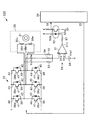
図1は、本発明に係るモータ制御装置の第1の実施の形態を示す電気回路図である。図2は、図1のモータが内蔵された圧縮機を備えた空気調和装置を示す冷媒回路図である。
【0019】
図2に示すように、空気調和装置10は、室外機11及び室内機12を有してなり、室外機11の室外冷媒配管14と室内機12の室内冷媒配管15とが、連結配管24、25を介して連結されている。
【0020】
室外機11は室外に配置される。室外冷媒配管14には、圧縮機16が配設されるとともに、この圧縮機16の吸込側にアキュムレータ17が配設され、圧縮機16の吐出側に四方弁18が配設され、この四方弁18側に室外熱交換器19が配設されて構成される。室外熱交換器19には、室外熱交換器19から室外へ送風する室外ファン20が隣接して配置されている。この室外ファン20は、室内ファンモータ20Aによって駆動される。この室外ファン20は、例えば、プロペラファンである。圧縮機16は、インバータ駆動型圧縮機である。この圧縮機16には、インバータによって駆動されるモータとしてのブラシレスDCモータ29が内蔵されている。
【0021】
室内機12は室内に設置され、室内冷媒配管15には室内熱交換器21及び電子膨張弁22が順次配設される。この室内熱交換器21には、室内熱交換器21から室内へ送風する室内ファン23が隣接して配置されている。この室内ファン23は、室内ファンモータ23Aによって駆動される。この室内ファン23は、例えば、クロスフローファンである。
【0022】
室外機11の四方弁18が切り換えられることにより、空気調和装置10が冷房運転又は暖房運転に設定される。つまり、四方弁18が冷房側に切り換えられたときには、冷媒が実線矢印の如く流れ、室外熱交換器19が凝縮器に、室内熱交換器21が蒸発器になって冷房運転状態となり、室内機12の室内熱交換器21が室内を冷房する。また、四方弁18が暖房側に切り換えられたときには、冷媒が破線矢印の如く流れ、室内熱交換器21が凝縮器に、室外熱交換器19が蒸発器になって暖房運転状態となり、室内機12の室内熱交換器21が室内を暖房する。
【0023】
上記圧縮機16内に内蔵されたブラシレスDCモータ29は、図1に示すように、固定子巻線30u、30v及び30wを備える固定子(ステータ)30と、永久磁石を備える回転子(ロータ)31とを有してなる三相モータである。このブラシレスDCモータ29がインバータ32、ロータ位置検出回路33及びマイクロコンピュータで構成される制御部34を備えたモータ制御装置100により駆動される。通常、圧縮機16のブラシレスDCモータ29は、空調負荷に応じて回転数制御が行われる。
【0024】
上記インバータ32は、例えば6個のスイッチング素子としてのトランジスタ38u、38v、38w、38x、38y及び38zを三相ブリッジ接続したものである。これらトランジスタ38u、38v、38w、38x、38y及び38zの各エミッタ端子39及び各コレクタ端子40間には、フライホイールダイオード42が接続されている。
【0025】
そして、インバータ32は、制御部34のPWM(Pulse Width Modulation)端子35から出力されたパルス幅変調されたスイッチング信号(以下、「PWMスイッチング信号」という。)が、トランジスタ38u、38v、38w、38x、38y、38zの各ベース端子41に入力されることにより動作する。
【0026】
このインバータ32の動作によって、交流電源(不図示)の交流電力が変換された直流電力が、所定の周波数と電圧を有するパルス幅変調を受けた三相交流電力に変換されて、三相の交流電圧Vu、Vv、VwがブラシレスDCモータ29の固定子巻線30u、30v、30wへ印加される。ここで、VuはU相電圧、VvはV相電圧、VwはW相電圧を示している。
【0027】
本実施の形態では、モータ制御装置100は、ブラシレスDCモータ29に三相の交流電圧を120度通電するようにインバータ32を制御する120度通電矩形波駆動方式でブラシレスDCモータ29を駆動している。
【0028】
ここで、トランジスタ38u、38v及び38wはインバータ32の上アームのトランジスタ群と称され、トランジスタ38x、38y、38zはインバータ32の下アームのトランジスタ群と称される。そして、トランジスタ38uと38xとが、トランジスタ38vと38yとが、トランジスタ38wと38zとがそれぞれ対をなし、それぞれの接続点が、スター接続されたブラシレスDCモータ29の固定子巻線30u、30v、30wにそれぞれ接続される。
【0029】
ロータ位置検出回路33は、ブラシレスDCモータ29の入力端子電圧の無通電相の誘起電圧を検出し、ロータ31の位置を示す信号を制御部34に出力する。
【0030】
このロータ位置検出回路33は、コンパレータ51及びフォトカプラ52を備えている。コンパレータ51の入力端子51aは、ブラシレスDCモータ29のU相、V相、W相の入力端子(インバータ32のU相、V相、W相の出力端子)に各抵抗53、54、55を介して接続される。また、入力端子51bには、直流の基準電圧Vrefを生成する基準電圧電源56が接続される。コンパレータ51の出力端子51cは、抵抗57を介してフォトカプラ52の入力端子52aに接続され、フォトカプラ52の出力端子52bは、制御部34の入力端子36に接続される。
【0031】
コンパレータ51は、抵抗53、54、55を介して検出した誘起電圧を示す入力信号と、基準電圧Vrefとを比較し、入力信号が基準電圧Vrefよりも高い場合はHレベル(例えば、5[V])の信号を出力し、低い場合はLレベル(例えば、0.6[V])の信号を出力する。
【0032】
フォトカプラ52は、マイクロコンピュータである制御部34を保護するために設けられており、コンパレータ51の出力であるHレベル或いはLレベルの信号を、制御部34に出力している。
【0033】
制御部34は、ブラシレスDCモータ29の現状の回転数と目標回転数とを比較し、この比較の結果に基づいてブラシレスDCモータ29に印加すべき印加電圧及び印加電圧の周波数を求め、更にPWMスイッチング信号のデューティ比を求めている。
【0034】
また、制御部34は、ロータ位置検出回路33からの出力信号に基づいてロータの位置を推定し、この推定結果に基づいてブラシレスDCモータ29に印加すべき各相の印加電圧の位相を求めている。
【0035】
そして、制御部34は、求めた印加電圧の周波数、PWMスイッチング信号のデューティ比及び印加電圧の位相に基づいて、PWMスイッチング信号を生成し、PWM端子35を通じてインバータ32に出力する。
【0036】
図3は、ブラシレスDCモータ29の入力端子の相電圧を示す概略波形図である。図3(a)はU相電圧波形であり、(b)はV相電圧波形であり、(c)はW相電圧波形であり、(d)は三相の誘起電圧波形である。
【0037】
例えば、図3(a)を参照して説明すると、U相電圧Vuの1周期には、PWMスイッチング信号がインバータ32に入力されてブラシレスDCモータ29に電圧を印加する電気角120度の通電期間Ta、Tcと、PWMスイッチング信号がインバータ32に入力されずに無通電相となる電気角60度の無通電期間Tb、Tdとが設けられている。これら無通電期間Tb、Tdでは、ロータ31の位置に応じた誘起電圧が発生する。V相電圧Vvは、図3(b)に示すように、U相電圧Vuよりも位相が120度ずれており、更にW相電圧Vwは、図3(c)に示すように、V相電圧Vvよりも位相が120度ずれている。そして、三相の合計の誘起電圧、即ちロータ位置検出回路33のコンパレータ51の入力端子51aに生じる電圧波形は、図3(d)に示すように、パルス状の三角波となる。
【0038】
制御部34からインバータ32に出力されるPWMスイッチング信号のキャリア周波数及びパルス幅と、誘起電圧として現れるパルス状の電圧の周波数及びパルス幅は、ほぼ同じである。したがって、PWMスイッチング信号のキャリア周波数が変化すれば、誘起電圧として現れるパルス状の電圧の周波数も同様に変化し、PWMスイッチング信号のパルス幅が変化すれば、誘起電圧のパルス幅も同様に変化する。例えば、PWMスイッチング信号のパルス幅が短くなれば、誘起電圧のパルス幅も同様に短くなる。
【0039】
コンパレータ51及びフォトカプラ52を有するロータ位置検出回路33は、入力されるパルス幅が所定のパルス幅(例えば、5[μs])よりも短くなると、回路の応答特性により、入力端子51aへの入力信号に対して追従できなくなる。つまり、ロータ位置検出回路33は、入力端子51aへの入力信号、即ち、PWMスイッチング信号のパルス幅が、所定のパルス幅(例えば、5[μs])よりも短くなると、入力に対して応答できずに、出力信号が不安定になることがある。従って、制御部34に正確にロータ31の位置を推定させるには、このロータ位置検出回路33への入力信号(パルス)が所定のパルス幅(例えば、5[μs])以上でなければならない。
【0040】
本実施の形態では、制御部34は、ブラシレスDCモータ29の印加電圧に対応するデューティ比を有するPWMスイッチング信号を生成するに際し、PWMスイッチング信号のパルス幅が所定のパルス幅(例えば、5[μs])以上となるようにPWMスイッチング信号のキャリア周波数を調整している。
【0041】
具体的に図4に示すデューティ比に対応するキャリア周波数及びブラシレスDCモータ29の印加電圧を示す説明図を参照して説明すると、まず、制御部34は、PWMスイッチング信号のデューティ比にしきい値Aを設定している。
【0042】
ここで、しきい値Aは、PWMスイッチング信号のキャリア周波数Bを一定(例えば、5[kHz])にしてPWMスイッチング信号のパルス幅を調整する場合のパルス幅が所定のパルス幅(例えば、5[μs])以上となるデューティ比の範囲内に設定される。
【0043】
例えば、PWMスイッチング信号のキャリア周波数Bが5[kHz]、PWMスイッチング信号のデューティ比が5[%]である場合、パルス幅が10[μs]となるので、しきい値Aを、例えば5[%]に設定する。
【0044】
そして、制御部34は、ブラシレスDCモータ29の印加電圧(線間電圧或いは相電圧)Cに対応するデューティ比を有するPWMスイッチング信号を生成するに際し、PWMスイッチング信号のデューティ比がしきい値Aを下回る場合、PWMスイッチング信号のパルス幅が、所定のパルス幅(例えば、5[μs])よりも短くなるのを防止すべく、所定のパルス幅以上となるように、キャリア周波数Bを調整している。
【0045】
より具体的には、制御部34は、ブラシレスDCモータ29の印加電圧(線間電圧或いは相電圧)Cに対応するデューティ比を有するPWMスイッチング信号を生成するに際し、生成するPWMスイッチング信号のデューティ比がしきい値A(例えば、5[%])を下回る場合、つまり、生成するPWMスイッチング信号のデューティ比がしきい値A(例えば、5[%])よりも小さいデューティ比範囲X内である場合、PWMスイッチング信号のパルス幅が、所定のパルス幅(例えば、5[μs])よりも短くなるのを防止すべく、所定のパルス幅以上となるように、デューティ比の低下に応じて連続的にキャリア周波数Bを低下させている。
【0046】
例えば、制御部34は、生成するPWMスイッチング信号のデューティ比がしきい値Aを下回る場合、PWMスイッチング信号のパルス幅を所定のパルス幅(例えば、5[μs])以上のパルス幅(例えば、10[μs])に一定とし、デューティ比の低下に応じて連続的にキャリア周波数Bを低下させている。このとき、一定とするパルス幅を、デューティ比がしきい値A(例えば、5[%])におけるパルス幅と同じ幅に設定するのが好ましい。
【0047】
ここで、同一のデューティ比であっても、キャリア周波数Bが低下すると、PWMスイッチング信号のパルス幅は長くなる。例えば、デューティ比5[%]のPWMスイッチング信号を生成する際、キャリア周波数B’が5[kHz]のとき、パルス幅は10[μs]であるが、キャリア周波数B’が2.5[kHz]のとき、パルス幅は20[μs]となる。つまり、キャリア周波数B’の低下に応じてPWMスイッチング信号のパルス幅が長くなる。
【0048】
従って、本第1の実施の形態によれば、制御部34は、インバータ32に印加される直流電圧が上昇したとき、又はブラシレスDCモータ29の回転数を下げるときに、ブラシレスDCモータ29への印加電圧を下げるべく、PWMスイッチング信号のデューティ比をしきい値Aを下回る値に制御する場合、ロータ位置検出回路33に入力される誘起電圧を示す入力信号のパルス幅が、所定のパルス幅を下回ることはないので、ブラシレスDCモータ29への印加電圧を低下させる制御を行っても、安定してロータ位置を推定することができる。
【0049】
また、制御部34は、ブラシレスDCモータ29の印加電圧Cに対応するデューティ比を有するPWMスイッチング信号を生成するに際し、PWMスイッチング信号のデューティ比がしきい値A(例えば、5[%])を上回る場合、つまり、生成するPWMスイッチング信号のデューティ比がしきい値A(例えば、5[%])よりも大きいデューティ比範囲Y内である場合、スイッチング信号のパルス幅が所定のパルス幅(例えば、5[μs])よりも短くなることはないので、キャリア周波数Bを一定(例えば、5[kHz])としている。
【0050】
ここで、制御部34は、ブラシレスDCモータ29を駆動する場合、回転数が0とならないように制御している。つまり、制御部34は、印加電圧が0[V]近傍となるのを回避すべく、ブラシレスDCモータ29に印加する最低の印加電圧を設けており、ブラシレスDCモータ29を駆動する場合には、この最低の印加電圧を下回らないように制御している。従って、印加電圧が0[V]或いは0[V]近傍となることはないので、キャリア周波数が極端に低下することを防止している。従って、安定してロータ位置を推定することができる。
[2]第2の実施の形態
上記第1の実施の形態では、制御部34が、デューティ比の低下に応じて連続的にキャリア周波数Bを低下させている場合について説明したが、本第2の実施の形態では、制御部が、デューティ比の低下に応じて段階的にキャリア周波数を低下させるものである。尚、システムの構成は、第1の実施の形態の図1及び図2と同様であるので、説明を省略するものとする。
【0051】
図5は、デューティ比に対応するキャリア周波数を示す説明図である。
【0052】
まず、制御部34は、第1の実施の形態の図4と同様に、PWMスイッチング信号のデューティ比にしきい値A(例えば、5[%])を設定している。
【0053】
そして、制御部34は、ブラシレスDCモータ29の印加電圧(線間電圧或いは相電圧)Cに対応するデューティ比を有するPWMスイッチング信号を生成するに際し、PWMスイッチング信号のデューティ比がしきい値Aを下回る場合、つまり、生成するPWMスイッチング信号のデューティ比がしきい値A(例えば、5[%])よりも小さいデューティ比範囲X内である場合、PWMスイッチング信号のパルス幅が、所定のパルス幅(例えば、5[μs])よりも短くなるのを防止すべく、所定のパルス幅以上となるように、デューティ比の低下に応じて段階的にキャリア周波数B’を低下させている。
【0054】
具体的には、制御部34は、キャリア周波数B’を、第1の周波数B1(例えば、5[kHz])からこの第1の周波数B1よりも低い第2の周波数B2(例えば、2.5[kHz])にデューティ比の低下に応じて段階的に低下させている。例えば、PWMスイッチング信号のデューティ比がしきい値Aを下回る場合、このしきい値Aを境にキャリア周波数B’を第1の周波数B1(例えば、5[kHz])からこの第1の周波数B1よりも低い第2の周波数B2(例えば、2.5[kHz])に低下させている。
【0055】
従って、インバータ32に印加される直流電圧が上昇したとき、又はブラシレスDCモータ29の回転数を下げるときに、ブラシレスDCモータ29への印加電圧を下げるべく、PWMスイッチング信号のデューティ比をしきい値Aを下回る値に制御する場合、段階的にキャリア周波数B’を低下させることで、PWMスイッチング信号のパルス幅が長くなるため、ロータ位置検出回路33に入力される誘起電圧を示す入力信号のパルス幅が、所定のパルス幅を下回ることはないので、ブラシレスDCモータ29への印加電圧を低下させる制御を行っても、安定してロータ位置を推定することができる。
【0056】
ここで、制御部34は、キャリア周波数B’が第1の周波数B1からこの第1の周波数B1よりも低い第2の周波数B2に変化するときと、第2の周波数B2から第1の周波数B1に変化するときとでデューティ比が異なるようにヒステリシス(ディファレンシャル)Δを持たせて制御している。
【0057】
具体的には、制御部34は、第1の周波数B1から第2の周波数B2に変化するときのデューティ比Aが、第2の周波数B2から第1の周波数B1に変化するデューティ比A’よりも低くなるようにヒステリシスΔを持たせて制御している。
【0058】
これによって、キャリア周波数B’が段階的に切り替わる境界において、ハンチングが生じるのを防止している。これによって、更に安定してロータ位置を推定することができる。
【0059】
このとき、デューティ比Aとデューティ比A’とのヒステリシスΔは、デューティ比Aのときの印加電圧(線間電圧或いは相電圧)に対して、デューティ比A’のときの印加電圧が、ハンチングが起こらない所定倍数(例えば、1.5倍)となるように設定されている。
【0060】
また、印加電圧が0[V]近傍となるのを回避すべく、ブラシレスDCモータ29に印加する最低の印加電圧を設けており、ブラシレスDCモータ29を駆動する場合には、この最低の印加電圧を下回らないように制御しているので、極端にパルス幅が短くなることはなく、安定してロータ位置を推定することができる。
【0061】
以上の説明において、キャリア周波数B’を第1の周波数B1からこの第1の周波数B1よりも低い第2の周波数B2にデューティ比の低下に応じて段階的に低下させる制御として、しきい値Aを境にキャリア周波数B’を第1の周波数B1から第2の周波数B2に1段階だけ低下させる場合について説明したが、例えば図6に示すように、しきい値Aを境にデューティ比の低下に応じて複数段階(例えば2段階)低下させるようにしてもよい。この場合、図6中、デューティ比A’’を下回る場合、キャリア周波数B’は周波数B2から周波数B3に低下されるが、このとき、B2は第1の周波数であり、B3は第2の周波数である。更に、第1の周波数B2から第2の周波数B3に変化するときのデューティ比A’’が、第2の周波数B3から第1の周波数B2に変化するデューティ比A’’’よりも低くなるようにヒステリシスを持たせて制御してもよい。
【0062】
また、以上の説明において、モータ制御装置が圧縮機のモータを駆動する場合について説明したが、センサレス制御方式で誘起電圧に基づいてロータ位置を推定するものであれば、いかなるモータであっても適用することが可能である。例えば、室外ファンモータや室内ファンモータ等を駆動する場合にも適用することができる。
【0063】
【発明の効果】
本発明によれば、モータへの印加電圧を低下させる制御を行っても、安定してロータの位置を推定することができる。
【図面の簡単な説明】
【図1】本発明に係るモータ制御装置の第1の実施の形態を示す電気回路図である。
【図2】図1のモータが内蔵された圧縮機を備えた空気調和装置を示す冷媒回路図である。
【図3】モータの入力端子の相電圧を示す概略波形図であり、(a)はU相電圧波形、(b)はV相電圧波形、(c)はW相電圧波形、(d)は三相の誘起電圧波形である。
【図4】第1の実施の形態のデューティ比に対応するキャリア周波数及びモータへの印加電圧を示す説明図である。
【図5】第2の実施の形態のデューティ比に対応するキャリア周波数を示す説明図である。
【図6】変形例としてのデューティ比に対応するキャリア周波数を示す説明図である。
【符号の説明】
10 空気調和装置
29 ブラシレスDCモータ(モータ)
31 ロータ
32 インバータ
34 制御部(周波数調整手段、設定手段)
100 モータ制御装置[0001]
BACKGROUND OF THE INVENTION
The present invention relates to a motor control device and a motor control method, and more particularly to a motor control device and a motor control method for estimating the position of a rotor.
[0002]
[Prior art]
Conventionally, the position of the rotor is estimated based on the induced voltage of the non-energized phase of the motor driven by the inverter, and a switching signal that is pulse-width modulated based on the estimation result is output to the inverter, and the voltage applied to the motor is determined. A motor control device to be controlled is known (for example, see Patent Document 1).
[0003]
A brushless DC motor is known as the motor, and a control method (sensorless control method) is generally employed that detects an induced voltage and estimates the rotor position without providing a sensor that detects the rotor position. ing. In the motor control device, for example, a 120-degree energizing rectangular wave drive system that controls the inverter so that a three-phase AC voltage is energized 120 degrees to the motor is employed, and appears in the non-energized phase on the output side of the inverter. The position of the rotor is estimated by detecting the induced voltage.
[0004]
As a means for estimating the rotor position based on the induced voltage, the detected induced voltage and the reference voltage are compared by a rotor position detection circuit including a comparator, and an output signal of the rotor position detection circuit is input to the microcomputer, Estimating the position.
[0005]
The induced voltage appears as a pulse voltage corresponding to the switching signal, and the rotor position detection circuit compares the pulse voltage with a reference voltage based on the voltage value within the ON period of the pulse voltage.
[0006]
In this type of motor control device, the carrier frequency of the switching signal is fixed in order to reduce the applied voltage to the motor when the DC voltage applied to the inverter rises due to poor power supply conditions or when the rotational speed of the motor is reduced. The control for reducing the pulse width of the switching signal, that is, the control for decreasing the duty ratio of the switching signal is performed.
[0007]
[Patent Document 1]
JP 2002-186274 A
[0008]
[Problems to be solved by the invention]
However, in the motor control device, when the control is performed to reduce the duty ratio by shortening the pulse width of the switching signal in order to reduce the voltage applied to the motor, the pulse width of the pulsed induced voltage corresponding to the switching signal is also reduced. If the pulse width of the induced voltage is too short, the rotor position detection circuit cannot respond to the input due to the characteristics of the rotor position detection circuit, and the rotor position cannot be estimated.
[0009]
An object of the present invention has been made in consideration of the above-described circumstances, and a motor control device and a motor control that can stabilize the estimation of the rotor position even when control is performed to reduce the voltage applied to the motor. It is to provide a method.
[0010]
[Means for Solving the Problems]
In order to solve the above-mentioned problem, the rotor position is estimated based on the induced voltage of the non-energized phase of the motor driven by the inverter, and a pulse width modulated switching signal is output to the inverter based on the estimation result. In the motor control apparatus for controlling the voltage applied to the motor, setting means for setting a threshold value for the duty ratio of the switching signal, and when the switching signal is generated, the duty ratio of the switching signal satisfies the threshold value. If it falls below the pulse width of the switching signal,With a pulse width that enables position estimationIn a fixed state, the applied voltage is adjusted by changing the carrier frequency, and when the duty ratio of the switching signal exceeds the threshold value, the carrier frequency is changed.At a frequency that is greater than the pulse width that enables position estimationAdjusting means for adjusting the applied voltage by changing the pulse width of the switching signal in a fixed state.
[0011]
In this case, the adjusting unit may control the applied voltage not to be equal to or lower than a predetermined voltage when the duty ratio of the switching signal is lower than the threshold value.
[0012]
Further, the position of the rotor is estimated based on the induced voltage of the non-energized phase of the motor driven by the inverter, and a switching signal that is pulse-width modulated based on the estimation result is output to the inverter and applied to the motor. In the motor control method for controlling voltage, when a threshold value is set for the duty ratio of the switching signal and the switching signal is generated, when the duty ratio of the switching signal is lower than the threshold value, Pulse widthWith a pulse width that enables position estimationIn a fixed state, the applied voltage is adjusted by changing the carrier frequency, and when the duty ratio of the switching signal exceeds the threshold value, the carrier frequency is changed.At a frequency that is greater than the pulse width that enables position estimationThe applied voltage is adjusted by changing the pulse width of the switching signal in a fixed state.
[0018]
DETAILED DESCRIPTION OF THE INVENTION
Hereinafter, embodiments of the present invention will be described with reference to the drawings.
[1] First embodiment
FIG. 1 is an electric circuit diagram showing a first embodiment of a motor control device according to the present invention. FIG. 2 is a refrigerant circuit diagram showing an air conditioner including a compressor in which the motor of FIG. 1 is built.
[0019]
As shown in FIG. 2, the
[0020]
The
[0021]
The
[0022]
By switching the four-
[0023]
As shown in FIG. 1, the
[0024]
The
[0025]
In the
[0026]
By the operation of the
[0027]
In the present embodiment, the
[0028]
Here, the
[0029]
The rotor
[0030]
The rotor
[0031]
The
[0032]
The
[0033]
The
[0034]
The
[0035]
The
[0036]
FIG. 3 is a schematic waveform diagram showing the phase voltage at the input terminal of the
[0037]
For example, referring to FIG. 3A, in one cycle of the U-phase voltage Vu, the energization period of 120 degrees in electrical angle during which the PWM switching signal is input to the
[0038]
The carrier frequency and pulse width of the PWM switching signal output from the
[0039]
In the rotor
[0040]
In the present embodiment, when the
[0041]
Specifically, referring to the explanatory diagram showing the carrier frequency corresponding to the duty ratio shown in FIG. 4 and the applied voltage of the
[0042]
Here, the threshold A is a pulse width when the pulse width of the PWM switching signal is adjusted to a predetermined pulse width (eg, 5 [kHz], for example) with the carrier frequency B of the PWM switching signal being constant (eg, 5 [kHz]). [Μs]) is set within the range of the duty ratio.
[0043]
For example, when the carrier frequency B of the PWM switching signal is 5 [kHz] and the duty ratio of the PWM switching signal is 5 [%], the pulse width is 10 [μs]. %].
[0044]
When the
[0045]
More specifically, when the
[0046]
For example, when the duty ratio of the generated PWM switching signal is lower than the threshold value A, the
[0047]
Here, even if the duty ratio is the same, if the carrier frequency B decreases, the pulse width of the PWM switching signal becomes longer. For example, when generating a PWM switching signal with a duty ratio of 5%, when the carrier frequency B ′ is 5 [kHz], the pulse width is 10 [μs], but the carrier frequency B ′ is 2.5 [kHz]. ], The pulse width is 20 [μs]. That is, the pulse width of the PWM switching signal becomes longer as the carrier frequency B ′ decreases.
[0048]
Therefore, according to the first embodiment, when the DC voltage applied to the
[0049]
Further, when the
[0050]
Here, when the
[2] Second embodiment
In the first embodiment, the case where the
[0051]
FIG. 5 is an explanatory diagram showing the carrier frequency corresponding to the duty ratio.
[0052]
First, similarly to FIG. 4 of the first embodiment, the
[0053]
When the
[0054]
Specifically, the
[0055]
Therefore, when the DC voltage applied to the
[0056]
Here, the
[0057]
Specifically, the
[0058]
As a result, hunting is prevented from occurring at the boundary where the carrier frequency B 'is switched stepwise. As a result, the rotor position can be estimated more stably.
[0059]
At this time, the hysteresis Δ between the duty ratio A and the duty ratio A ′ is equal to the applied voltage (line voltage or phase voltage) when the duty ratio A is applied. It is set to be a predetermined multiple that does not occur (for example, 1.5 times).
[0060]
In addition, in order to avoid the applied voltage from being in the vicinity of 0 [V], the lowest applied voltage to be applied to the
[0061]
In the above description, the threshold A is used as a control for gradually decreasing the carrier frequency B ′ from the first frequency B1 to the second frequency B2 lower than the first frequency B1 in accordance with the decrease in the duty ratio. The case where the carrier frequency B ′ is decreased by one step from the first frequency B1 to the second frequency B2 has been described with reference to FIG. 6, but for example, as shown in FIG. Depending on the condition, it may be lowered by a plurality of stages (for example, two stages). In this case, in FIG. 6, when the duty ratio is less than A ″, the carrier frequency B ′ is lowered from the frequency B2 to the frequency B3. At this time, B2 is the first frequency, and B3 is the second frequency. It is. Further, the duty ratio A ″ when changing from the first frequency B2 to the second frequency B3 is lower than the duty ratio A ′ ″ changing from the second frequency B3 to the first frequency B2. Control may be performed with hysteresis.
[0062]
In the above description, the case where the motor control device drives the motor of the compressor has been described. However, any motor can be used as long as the rotor position is estimated based on the induced voltage in the sensorless control method. Is possible. For example, the present invention can be applied to driving an outdoor fan motor, an indoor fan motor, or the like.
[0063]
【The invention's effect】
According to the present invention, the position of the rotor can be stably estimated even when control is performed to reduce the voltage applied to the motor.
[Brief description of the drawings]
FIG. 1 is an electric circuit diagram showing a first embodiment of a motor control device according to the present invention.
FIG. 2 is a refrigerant circuit diagram showing an air conditioner including a compressor in which the motor of FIG. 1 is built.
3A and 3B are schematic waveform diagrams showing phase voltages at the input terminals of a motor, where FIG. 3A is a U-phase voltage waveform, FIG. 3B is a V-phase voltage waveform, FIG. 3C is a W-phase voltage waveform, and FIG. It is a three-phase induced voltage waveform.
FIG. 4 is an explanatory diagram showing a carrier frequency corresponding to a duty ratio of the first embodiment and a voltage applied to a motor.
FIG. 5 is an explanatory diagram showing a carrier frequency corresponding to the duty ratio of the second embodiment.
FIG. 6 is an explanatory diagram showing a carrier frequency corresponding to a duty ratio as a modified example.
[Explanation of symbols]
10 Air conditioner
29 Brushless DC motor (motor)
31 rotor
32 inverter
34 Control unit (frequency adjusting means, setting means)
100 Motor control device
Claims (3)
前記スイッチング信号のデューティ比にしきい値を設定する設定手段と、
前記スイッチング信号を生成するに際し、当該スイッチング信号のデューティ比が前記しきい値を下回る場合、当該スイッチング信号のパルス幅を位置の推定が可能となるパルス幅で固定した状態で、前記キャリア周波数を変化させることで前記印加電圧を調整し、当該スイッチング信号のデューティ比が前記しきい値を上回る場合、前記キャリア周波数を位置の推定が可能となるパルス幅以上となる周波数で固定した状態で、当該スイッチング信号のパルス幅を変化させることで前記印加電圧を調整する調整手段と、
を備えたことを特徴とするモータ制御装置。The position of the rotor is estimated based on the induced voltage of the non-energized phase of the motor driven by the inverter, and a switching signal that is pulse width modulated based on the estimation result is output to the inverter, and the voltage applied to the motor is determined. In the motor control device to control,
Setting means for setting a threshold to the duty ratio of the switching signal;
When generating the switching signal, if the duty ratio of the switching signal is lower than the threshold value, the carrier frequency is changed in a state where the pulse width of the switching signal is fixed at a pulse width that enables position estimation. When the applied voltage is adjusted and the duty ratio of the switching signal exceeds the threshold, the switching is performed in a state where the carrier frequency is fixed at a frequency that is equal to or greater than a pulse width that enables position estimation. Adjusting means for adjusting the applied voltage by changing the pulse width of the signal;
A motor control device comprising:
前記調整手段は、前記スイッチング信号のデューティ比が前記しきい値を下回る場合、前記印加電圧が所定の電圧以下にならないように制御することを特徴とするモータ制御装置。The motor control device according to claim 1,
The motor control apparatus according to claim 1, wherein the adjustment unit controls the applied voltage not to be equal to or lower than a predetermined voltage when a duty ratio of the switching signal is lower than the threshold value.
前記スイッチング信号のデューティ比にしきい値を設定し、
前記スイッチング信号を生成するに際し、当該スイッチング信号のデューティ比が前記しきい値を下回る場合、当該スイッチング信号のパルス幅を位置の推定が可能となるパルス幅で固定した状態で、前記キャリア周波数を変化させることで前記印加電圧を調整し、当該スイッチング信号のデューティ比が前記しきい値を上回る場合、前記キャリア周波数を位置の推定が可能となるパルス幅以上となる周波数で固定した状態で、当該スイッチング信号のパルス幅を変化させることで前記印加電圧を調整する、
ことを特徴とするモータの制御方法。The position of the rotor is estimated based on the induced voltage of the non-energized phase of the motor driven by the inverter, and a switching signal that is pulse width modulated based on the estimation result is output to the inverter, and the voltage applied to the motor is determined. In the control method of the motor to be controlled,
Set a threshold value for the duty ratio of the switching signal,
When generating the switching signal, if the duty ratio of the switching signal is lower than the threshold value, the carrier frequency is changed in a state where the pulse width of the switching signal is fixed at a pulse width that enables position estimation. When the applied voltage is adjusted and the duty ratio of the switching signal exceeds the threshold, the switching is performed in a state where the carrier frequency is fixed at a frequency that is equal to or greater than a pulse width that enables position estimation. Adjusting the applied voltage by changing the pulse width of the signal;
A method for controlling a motor.
Priority Applications (3)
| Application Number | Priority Date | Filing Date | Title |
|---|---|---|---|
| JP2003048699A JP4197974B2 (en) | 2003-02-26 | 2003-02-26 | Motor control device and motor control method |
| CNB2004100059995A CN1282300C (en) | 2003-02-26 | 2004-02-24 | Motor control device and method |
| KR1020040012449A KR20040076789A (en) | 2003-02-26 | 2004-02-25 | Motor Control Apparatus and Motor Control Method |
Applications Claiming Priority (1)
| Application Number | Priority Date | Filing Date | Title |
|---|---|---|---|
| JP2003048699A JP4197974B2 (en) | 2003-02-26 | 2003-02-26 | Motor control device and motor control method |
Publications (2)
| Publication Number | Publication Date |
|---|---|
| JP2004260919A JP2004260919A (en) | 2004-09-16 |
| JP4197974B2 true JP4197974B2 (en) | 2008-12-17 |
Family
ID=33114591
Family Applications (1)
| Application Number | Title | Priority Date | Filing Date |
|---|---|---|---|
| JP2003048699A Expired - Fee Related JP4197974B2 (en) | 2003-02-26 | 2003-02-26 | Motor control device and motor control method |
Country Status (3)
| Country | Link |
|---|---|
| JP (1) | JP4197974B2 (en) |
| KR (1) | KR20040076789A (en) |
| CN (1) | CN1282300C (en) |
Families Citing this family (8)
| Publication number | Priority date | Publication date | Assignee | Title |
|---|---|---|---|---|
| JP5015437B2 (en) * | 2005-08-26 | 2012-08-29 | ローム株式会社 | Motor drive device, method, and cooling device using the same |
| FR2911643B1 (en) * | 2007-01-19 | 2009-03-13 | Inergy Automotive Systems Res | METHOD AND SYSTEM FOR MONITORING THE OPERATION OF A PUMP |
| KR100904426B1 (en) * | 2007-09-11 | 2009-06-26 | 주식회사 하이닉스반도체 | Circuit of internal voltage generation |
| JP5496517B2 (en) * | 2008-03-26 | 2014-05-21 | 株式会社ミツバ | Motor control circuit |
| JP5772029B2 (en) * | 2011-02-08 | 2015-09-02 | アイシン精機株式会社 | Sensorless brushless motor drive device |
| JP5552701B2 (en) * | 2011-09-20 | 2014-07-16 | 日立オートモティブシステムズ株式会社 | Brushless motor drive device |
| CN104359184B (en) * | 2014-09-30 | 2017-02-15 | 海信科龙电器股份有限公司 | Carrier frequency conversion control method and controller |
| JP7296913B2 (en) * | 2020-04-10 | 2023-06-23 | 三菱電機株式会社 | pulse width modulation controller |
-
2003
- 2003-02-26 JP JP2003048699A patent/JP4197974B2/en not_active Expired - Fee Related
-
2004
- 2004-02-24 CN CNB2004100059995A patent/CN1282300C/en not_active Expired - Fee Related
- 2004-02-25 KR KR1020040012449A patent/KR20040076789A/en not_active Application Discontinuation
Also Published As
| Publication number | Publication date |
|---|---|
| JP2004260919A (en) | 2004-09-16 |
| KR20040076789A (en) | 2004-09-03 |
| CN1282300C (en) | 2006-10-25 |
| CN1543056A (en) | 2004-11-03 |
Similar Documents
| Publication | Publication Date | Title |
|---|---|---|
| US7688018B2 (en) | Inverter | |
| JP6721476B2 (en) | Motor drive system and air conditioner | |
| US20080072619A1 (en) | Control device of motor for refrigerant compressor | |
| KR100799009B1 (en) | Driving method and driver of brushless dc motor | |
| JP5505528B1 (en) | Power consumption reduction device | |
| JP2006101685A (en) | Inverter device | |
| JP4792849B2 (en) | DC power supply for air conditioner | |
| JP2009198139A (en) | Brushless motor driving device for compressor of air conditioner | |
| JP2002247876A (en) | Inverter device, compressor controlling device, freezer and air conditioner controlling device, motor controlling method, compressor, freezer and air conditioner | |
| JP6718356B2 (en) | Motor control device and heat pump type refrigeration cycle device | |
| JP5353021B2 (en) | Control device for electric compressor | |
| JP4197974B2 (en) | Motor control device and motor control method | |
| JP4226224B2 (en) | Inverter device | |
| JP2007116770A (en) | Motor driving unit and its control method, and air conditioner | |
| JP4791319B2 (en) | Inverter device, compressor drive device and refrigeration / air-conditioning device | |
| JP2008005592A (en) | Motor drive device and storage device with the motor drive device | |
| JP2004364492A (en) | Motor-driving device and air-conditioning equipment | |
| JP2003348885A (en) | Method and apparatus for controlling permanent magnet synchronous motor | |
| JP2003052191A (en) | Motor driver and drive method | |
| JP2003037988A (en) | Method and device for driving brushless dc motor | |
| JP2005207362A (en) | Driving device for electric compressor | |
| JP2009240147A (en) | Inverter apparatus | |
| JP4581391B2 (en) | Motor drive device | |
| JP2005065449A (en) | Motor control device | |
| JP3283793B2 (en) | Drive control device for brushless motor |
Legal Events
| Date | Code | Title | Description |
|---|---|---|---|
| A711 | Notification of change in applicant |
Free format text: JAPANESE INTERMEDIATE CODE: A712 Effective date: 20040819 |
|
| A521 | Written amendment |
Free format text: JAPANESE INTERMEDIATE CODE: A821 Effective date: 20040819 |
|
| A621 | Written request for application examination |
Free format text: JAPANESE INTERMEDIATE CODE: A621 Effective date: 20051013 |
|
| A977 | Report on retrieval |
Free format text: JAPANESE INTERMEDIATE CODE: A971007 Effective date: 20070626 |
|
| A131 | Notification of reasons for refusal |
Free format text: JAPANESE INTERMEDIATE CODE: A131 Effective date: 20071218 |
|
| A521 | Written amendment |
Free format text: JAPANESE INTERMEDIATE CODE: A523 Effective date: 20080212 |
|
| A131 | Notification of reasons for refusal |
Free format text: JAPANESE INTERMEDIATE CODE: A131 Effective date: 20080408 |
|
| A521 | Written amendment |
Free format text: JAPANESE INTERMEDIATE CODE: A523 Effective date: 20080604 |
|
| TRDD | Decision of grant or rejection written | ||
| A01 | Written decision to grant a patent or to grant a registration (utility model) |
Free format text: JAPANESE INTERMEDIATE CODE: A01 Effective date: 20080902 |
|
| A01 | Written decision to grant a patent or to grant a registration (utility model) |
Free format text: JAPANESE INTERMEDIATE CODE: A01 |
|
| A61 | First payment of annual fees (during grant procedure) |
Free format text: JAPANESE INTERMEDIATE CODE: A61 Effective date: 20080930 |
|
| FPAY | Renewal fee payment (event date is renewal date of database) |
Free format text: PAYMENT UNTIL: 20111010 Year of fee payment: 3 |
|
| FPAY | Renewal fee payment (event date is renewal date of database) |
Free format text: PAYMENT UNTIL: 20111010 Year of fee payment: 3 |
|
| FPAY | Renewal fee payment (event date is renewal date of database) |
Free format text: PAYMENT UNTIL: 20111010 Year of fee payment: 3 |
|
| S111 | Request for change of ownership or part of ownership |
Free format text: JAPANESE INTERMEDIATE CODE: R313115 |
|
| FPAY | Renewal fee payment (event date is renewal date of database) |
Free format text: PAYMENT UNTIL: 20111010 Year of fee payment: 3 |
|
| R350 | Written notification of registration of transfer |
Free format text: JAPANESE INTERMEDIATE CODE: R350 |
|
| FPAY | Renewal fee payment (event date is renewal date of database) |
Free format text: PAYMENT UNTIL: 20121010 Year of fee payment: 4 |
|
| FPAY | Renewal fee payment (event date is renewal date of database) |
Free format text: PAYMENT UNTIL: 20121010 Year of fee payment: 4 |
|
| FPAY | Renewal fee payment (event date is renewal date of database) |
Free format text: PAYMENT UNTIL: 20131010 Year of fee payment: 5 |
|
| LAPS | Cancellation because of no payment of annual fees |