WO2017203972A1 - 記録媒体搬送装置及びインクジェット記録装置 - Google Patents
記録媒体搬送装置及びインクジェット記録装置 Download PDFInfo
- Publication number
- WO2017203972A1 WO2017203972A1 PCT/JP2017/017547 JP2017017547W WO2017203972A1 WO 2017203972 A1 WO2017203972 A1 WO 2017203972A1 JP 2017017547 W JP2017017547 W JP 2017017547W WO 2017203972 A1 WO2017203972 A1 WO 2017203972A1
- Authority
- WO
- WIPO (PCT)
- Prior art keywords
- recording medium
- belt
- support plate
- roller
- transport
- Prior art date
- Legal status (The legal status is an assumption and is not a legal conclusion. Google has not performed a legal analysis and makes no representation as to the accuracy of the status listed.)
- Ceased
Links
Images




Classifications
-
- B—PERFORMING OPERATIONS; TRANSPORTING
- B41—PRINTING; LINING MACHINES; TYPEWRITERS; STAMPS
- B41J—TYPEWRITERS; SELECTIVE PRINTING MECHANISMS, i.e. MECHANISMS PRINTING OTHERWISE THAN FROM A FORME; CORRECTION OF TYPOGRAPHICAL ERRORS
- B41J11/00—Devices or arrangements of selective printing mechanisms, e.g. ink-jet printers or thermal printers, for supporting or handling copy material in sheet or web form
- B41J11/0015—Devices or arrangements of selective printing mechanisms, e.g. ink-jet printers or thermal printers, for supporting or handling copy material in sheet or web form for treating before, during or after printing or for uniform coating or laminating the copy material before or after printing
- B41J11/002—Curing or drying the ink on the copy materials, e.g. by heating or irradiating
- B41J11/0024—Curing or drying the ink on the copy materials, e.g. by heating or irradiating using conduction means, e.g. by using a heated platen
-
- B—PERFORMING OPERATIONS; TRANSPORTING
- B41—PRINTING; LINING MACHINES; TYPEWRITERS; STAMPS
- B41J—TYPEWRITERS; SELECTIVE PRINTING MECHANISMS, i.e. MECHANISMS PRINTING OTHERWISE THAN FROM A FORME; CORRECTION OF TYPOGRAPHICAL ERRORS
- B41J11/00—Devices or arrangements of selective printing mechanisms, e.g. ink-jet printers or thermal printers, for supporting or handling copy material in sheet or web form
- B41J11/0015—Devices or arrangements of selective printing mechanisms, e.g. ink-jet printers or thermal printers, for supporting or handling copy material in sheet or web form for treating before, during or after printing or for uniform coating or laminating the copy material before or after printing
- B41J11/002—Curing or drying the ink on the copy materials, e.g. by heating or irradiating
- B41J11/0021—Curing or drying the ink on the copy materials, e.g. by heating or irradiating using irradiation
- B41J11/00216—Curing or drying the ink on the copy materials, e.g. by heating or irradiating using irradiation using infrared [IR] radiation or microwaves
-
- B—PERFORMING OPERATIONS; TRANSPORTING
- B41—PRINTING; LINING MACHINES; TYPEWRITERS; STAMPS
- B41J—TYPEWRITERS; SELECTIVE PRINTING MECHANISMS, i.e. MECHANISMS PRINTING OTHERWISE THAN FROM A FORME; CORRECTION OF TYPOGRAPHICAL ERRORS
- B41J11/00—Devices or arrangements of selective printing mechanisms, e.g. ink-jet printers or thermal printers, for supporting or handling copy material in sheet or web form
- B41J11/007—Conveyor belts or like feeding devices
-
- B—PERFORMING OPERATIONS; TRANSPORTING
- B41—PRINTING; LINING MACHINES; TYPEWRITERS; STAMPS
- B41J—TYPEWRITERS; SELECTIVE PRINTING MECHANISMS, i.e. MECHANISMS PRINTING OTHERWISE THAN FROM A FORME; CORRECTION OF TYPOGRAPHICAL ERRORS
- B41J11/00—Devices or arrangements of selective printing mechanisms, e.g. ink-jet printers or thermal printers, for supporting or handling copy material in sheet or web form
- B41J11/0085—Using suction for maintaining printing material flat
-
- B—PERFORMING OPERATIONS; TRANSPORTING
- B41—PRINTING; LINING MACHINES; TYPEWRITERS; STAMPS
- B41J—TYPEWRITERS; SELECTIVE PRINTING MECHANISMS, i.e. MECHANISMS PRINTING OTHERWISE THAN FROM A FORME; CORRECTION OF TYPOGRAPHICAL ERRORS
- B41J11/00—Devices or arrangements of selective printing mechanisms, e.g. ink-jet printers or thermal printers, for supporting or handling copy material in sheet or web form
- B41J11/02—Platens
- B41J11/06—Flat page-size platens or smaller flat platens having a greater size than line-size platens
-
- B—PERFORMING OPERATIONS; TRANSPORTING
- B65—CONVEYING; PACKING; STORING; HANDLING THIN OR FILAMENTARY MATERIAL
- B65H—HANDLING THIN OR FILAMENTARY MATERIAL, e.g. SHEETS, WEBS, CABLES
- B65H5/00—Feeding articles separated from piles; Feeding articles to machines
- B65H5/02—Feeding articles separated from piles; Feeding articles to machines by belts or chains, e.g. between belts or chains
-
- B—PERFORMING OPERATIONS; TRANSPORTING
- B65—CONVEYING; PACKING; STORING; HANDLING THIN OR FILAMENTARY MATERIAL
- B65H—HANDLING THIN OR FILAMENTARY MATERIAL, e.g. SHEETS, WEBS, CABLES
- B65H5/00—Feeding articles separated from piles; Feeding articles to machines
- B65H5/02—Feeding articles separated from piles; Feeding articles to machines by belts or chains, e.g. between belts or chains
- B65H5/021—Feeding articles separated from piles; Feeding articles to machines by belts or chains, e.g. between belts or chains by belts
-
- B—PERFORMING OPERATIONS; TRANSPORTING
- B65—CONVEYING; PACKING; STORING; HANDLING THIN OR FILAMENTARY MATERIAL
- B65H—HANDLING THIN OR FILAMENTARY MATERIAL, e.g. SHEETS, WEBS, CABLES
- B65H5/00—Feeding articles separated from piles; Feeding articles to machines
- B65H5/08—Feeding articles separated from piles; Feeding articles to machines by grippers, e.g. suction grippers
- B65H5/085—Feeding articles separated from piles; Feeding articles to machines by grippers, e.g. suction grippers by combinations of endless conveyors and grippers
-
- B—PERFORMING OPERATIONS; TRANSPORTING
- B65—CONVEYING; PACKING; STORING; HANDLING THIN OR FILAMENTARY MATERIAL
- B65H—HANDLING THIN OR FILAMENTARY MATERIAL, e.g. SHEETS, WEBS, CABLES
- B65H5/00—Feeding articles separated from piles; Feeding articles to machines
- B65H5/22—Feeding articles separated from piles; Feeding articles to machines by air-blast or suction device
-
- B—PERFORMING OPERATIONS; TRANSPORTING
- B65—CONVEYING; PACKING; STORING; HANDLING THIN OR FILAMENTARY MATERIAL
- B65H—HANDLING THIN OR FILAMENTARY MATERIAL, e.g. SHEETS, WEBS, CABLES
- B65H5/00—Feeding articles separated from piles; Feeding articles to machines
- B65H5/22—Feeding articles separated from piles; Feeding articles to machines by air-blast or suction device
- B65H5/222—Feeding articles separated from piles; Feeding articles to machines by air-blast or suction device by suction devices
- B65H5/224—Feeding articles separated from piles; Feeding articles to machines by air-blast or suction device by suction devices by suction belts
-
- B—PERFORMING OPERATIONS; TRANSPORTING
- B65—CONVEYING; PACKING; STORING; HANDLING THIN OR FILAMENTARY MATERIAL
- B65H—HANDLING THIN OR FILAMENTARY MATERIAL, e.g. SHEETS, WEBS, CABLES
- B65H5/00—Feeding articles separated from piles; Feeding articles to machines
- B65H5/36—Article guides or smoothers, e.g. movable in operation
-
- B—PERFORMING OPERATIONS; TRANSPORTING
- B65—CONVEYING; PACKING; STORING; HANDLING THIN OR FILAMENTARY MATERIAL
- B65H—HANDLING THIN OR FILAMENTARY MATERIAL, e.g. SHEETS, WEBS, CABLES
- B65H2404/00—Parts for transporting or guiding the handled material
- B65H2404/20—Belts
- B65H2404/25—Driving or guiding arrangements
- B65H2404/253—Relative position of driving and idler rollers
-
- B—PERFORMING OPERATIONS; TRANSPORTING
- B65—CONVEYING; PACKING; STORING; HANDLING THIN OR FILAMENTARY MATERIAL
- B65H—HANDLING THIN OR FILAMENTARY MATERIAL, e.g. SHEETS, WEBS, CABLES
- B65H2404/00—Parts for transporting or guiding the handled material
- B65H2404/20—Belts
- B65H2404/25—Driving or guiding arrangements
- B65H2404/255—Arrangement for tensioning
Definitions
- the present invention relates to a recording medium conveying apparatus and an ink jet recording apparatus.
- an ink jet recording apparatus that records an image on a recording medium by ejecting ink droplets onto the recording medium.
- a two-dimensional image is recorded on a recording medium by relatively moving an inkjet head that discharges ink droplets and the recording medium.
- an inkjet recording apparatus is configured so that at least the recording medium can be transported. After an image is recorded on the recording medium supplied from the medium supply unit, the recording medium is Discharge to the media discharge unit.
- An object of the present invention is to provide a recording medium conveying apparatus and an ink jet recording apparatus that can convey a recording medium with higher positional accuracy.
- a recording medium conveying apparatus of an ink jet recording apparatus that records an image by discharging ink from a recording head to a recording medium
- An endless belt-like member for placing the recording medium on the outer peripheral surface
- the two belt rollers that span the belt-like member and move the belt-like member around in response to a rotation operation;
- a drive unit for rotating at least one of the two transport rollers;
- a support plate that supports the inner peripheral surface of the belt-like member in a plane in one section where the outer peripheral surface is opposed to the ink ejection surface of the recording head between the two transport rollers of the belt-like member;
- a suction section that sucks air from the outer peripheral surface side of the belt-shaped member through the hole portions in the belt-shaped member and the support plate, and adsorbs the recording medium placed on the belt-shaped member to the outer peripheral surface of the belt-shaped member.
- a guide roller provided on at least one of the two transport rollers and the support plate to support the inner peripheral surface of the belt-shaped member; With The guide roller is provided such that the belt-like member moves between the guide roller and the support plate on the same plane as the support plate.
- the invention according to claim 2 is the recording medium transport apparatus according to claim 1,
- the transport roller in which the guide roller is provided between the support plate and the belt-shaped member between the transport roller and the guide roller provided between the transport roller and the support plate. It is provided to move in a direction intersecting with the plane at a predetermined angle.
- the invention according to claim 3 is the recording medium conveying apparatus according to claim 2,
- the band-shaped member is characterized in that a recording medium is placed in a section that moves on the plane.
- the recording medium conveying apparatus according to any one of the first to third aspects,
- the support plate is formed using a porous body.
- the invention according to claim 5 is the recording medium conveying apparatus according to any one of claims 1 to 4,
- the belt-shaped member is a steel belt.
- the invention according to claim 6 is the recording medium conveying apparatus according to any one of claims 1 to 5,
- the rotation radius of the guide roller is smaller than the rotation radius of the transport roller.
- the invention according to claim 7 is the recording medium conveying apparatus according to any one of claims 1 to 6,
- a floating suppression unit is provided that guides the recording medium placed on the strip member along the surface of the strip member. It is characterized by.
- the invention according to claim 8 is the recording medium transport apparatus according to claim 7,
- the guide roller is provided on the upstream side of the support plate at least in the conveyance direction of the recording medium,
- the floating suppression unit is provided at a position facing the guide roller with the belt-like member interposed therebetween.
- the invention according to claim 9 is the recording medium conveying apparatus according to claim 7,
- the guide roller is provided between the two transport rollers and the support plate,
- the levitation suppression unit is provided at a position facing each of the two guide rollers with the belt-like member interposed therebetween.
- the invention according to claim 10 is the recording medium conveying apparatus according to any one of claims 1 to 9, Of the section between the two transport rollers in the strip member, in the section on the opposite side to the one section, at each position in the width direction perpendicular to the moving direction of the strip member that moves around, the strip It is characterized by including a tension adjusting section that applies a uniform tension to the member.
- the invention according to claim 11 is the recording medium conveying apparatus according to any one of claims 1 to 10, wherein A heating unit that heats the recording medium upstream of the support plate in the transport direction of the recording medium by the belt-shaped member is provided.
- the invention according to claim 12 is the recording medium transport apparatus according to claim 11,
- the heating unit heats the strip member to heat the recording medium via the strip member.
- the invention according to claim 13 is the recording medium conveying apparatus according to claim 11,
- the heating unit has a heat source in at least one of roller members in contact with at least one of the belt-shaped member and the recording medium.
- a recording medium conveying apparatus according to any one of claims 1 to 13, The recording head for ejecting ink to a recording medium conveyed by the recording medium conveying device;
- An ink jet recording apparatus comprising:
- the recording medium can be conveyed with higher positional accuracy in the recording medium conveying apparatus of the ink jet recording apparatus.
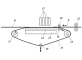
- FIG. 1 is a diagram schematically illustrating a configuration of an ink jet recording apparatus including a recording medium conveying apparatus according to an embodiment of the present invention. It is the figure which expanded the structure of the conveyance part in the front and back of a guide roller. It is a figure which shows the example of the structure of a drive roller. It is a figure which shows the modification 1 of a conveyance part. It is a figure which shows the modification 2 of a conveyance part.
- FIG. 1 is a diagram illustrating an overall configuration of an ink jet recording apparatus 100 including a transport unit 10 that is a recording medium transport apparatus of the present embodiment.
- the inkjet recording apparatus 100 includes a medium supply unit 30, a transport unit 10, an image recording unit 20, a medium discharge unit 40, and the like.
- the medium supply unit 30 includes a loading tray 31 and a medium output unit 32.
- the loading tray 31 is a plate-like member on which an individual recording medium P such as one or a plurality of sheets can be loaded, and is sent to the transport unit 10 in order from the recording medium P placed on the top. Is done.
- the loading tray 31 is movable in the vertical direction, and the uppermost recording medium P is held at the delivery position to the transport unit 10 according to the total weight of the loaded recording medium P or the like.
- the type of the recording medium P is not particularly limited, and here, for example, a cardboard material is used.
- the degree of change in the height of the loading tray 31 may be adjustable according to the type of the recording medium P by setting or the like.
- the medium output unit 32 has, for example, a rotatable roller that holds the medium to be sent from above and below, and sends the recording medium P in the horizontal direction here.
- the medium output unit 32 further includes an endless delivery belt that places and sends the recording medium P at the same height as the upper surface (support surface) of the support plate 14 up to the vicinity of the guide roller 16, and the delivery belt bridges. Two rollers may be provided.
- the transport unit 10 receives and transports the recording medium P from the medium supply unit 30 and sends it to the medium discharge unit 40.
- the conveyance unit 10 includes a driving roller 11, a driven roller 12, a conveyance belt 13 (band member), a support plate 14 (platen), a suction unit 15, guide rollers 16 and 17, and a pressing roller 18 (lift suppression). Part) and a tension roller 19 (tension adjusting part).
- the conveyance belt 13 is an endless belt, and a steel belt is used here. Examples of the material include SUS304, SUS631, aluminum alloy, and the like.
- the conveyor belt 13 is stretched between a driving roller 11 and a driven roller 12 (these are collectively referred to as two conveyor rollers 11 and 12), and the driving roller 11 rotates according to the rotation operation of the conveyor motor. Thus, it moves around in accordance with the rotation speed and the rotation direction.
- the driving roller 11 rotates counterclockwise in the plane of FIG. 1, the conveyance belt 13 moves in the normal conveyance direction of the recording medium P.
- the recording medium P sent from the medium supply unit 30 is placed on the outer peripheral surface of the conveying belt 13 (that is, the surface not in contact with the conveying rollers 11 and 12). It is conveyed with the movement.
- the recording medium P to be transported in the section between the two transport rollers 11 and 12 of the transport belt 13, that is, the outer peripheral surface of the transport belt 13 is the head unit 21 (ink discharge surface of the recording head).
- the inner peripheral surface (surface on the side in contact with the transport rollers 11, 12) of the transport belt 13 is supported by a flat surface (here, a horizontal surface) within a range including the facing portion in one facing section.
- the upper surface (support surface) of the support plate 14 that forms this plane is disposed in the horizontal direction at a position higher than the line connecting the upper ends of the drive roller 11 and the driven roller 12.
- the conveyor belt 13 supported by the support plate 14 moves the recording medium P sent from the medium supply unit 30 in the horizontal direction on the support plate 14 while placing the recording medium P in the vertical direction without causing a change in position. .
- the longer the support plate 14 in the conveyance direction the easier it is to stabilize the recording medium P during image recording by the image recording unit 20, but the area occupied in the horizontal direction increases.
- the support plate 14 has an appropriate length, for example, a length in the conveyance direction of the recording medium P (if a single size is used, image recording is performed on the recording medium P having a plurality of sizes based on the single size. If possible, it is preferably determined to a degree (based on standard length or maximum length, etc.).
- the conveyor belt 13 and the support plate 14 have a large number of holes and allow air to pass therethrough.
- the support plate 14 various known porous bodies whose upper surfaces are processed into a flat shape are used.
- the size, number, and arrangement of the holes of the conveyance belt 13 are determined within a range where the recording medium P is uniformly placed.
- the suction portion 15 is provided below the support plate 14, that is, on the side opposite to the side in contact with the conveyance belt 13, and from the outer peripheral surface side of the conveyance belt 13 through the holes of the conveyance belt 13 and the support plate 14. By sucking air, the recording medium P placed on the outer peripheral surface of the conveyor belt 13 is adsorbed to the conveyor belt 13.
- a guide roller 16 is provided on the upstream side of the support plate 14 and a guide roller 17 is provided on the downstream side of the support plate 14 in the moving direction of the conveyance belt 13 (the conveyance direction of the recording medium P). Yes.
- the guide rollers 16 and 17 support the conveyance belt 13 on both outer sides of the support surface.
- FIG. 2 is an enlarged view of the configuration of the transport unit 10 before and after the guide roller 16.
- the guide rollers 16 and 17 support the transport belt 13 at the same height as the support surface of the support plate 14. That is, the transport belt 13 moves from a position in contact with the driven roller 12 to a position in contact with the guide roller 16 including a component upward in the vertical direction, and moves to a position in contact with the support surface of the support plate 14 by changing the direction in the horizontal direction. To do. Further, the transport belt 13 that moves from a position in contact with the support surface of the support plate 14 moves in the horizontal direction as it is to a position in contact with the guide roller 17, and then comes into contact with the drive roller 11 including a vertically downward component. Move to position.
- the same height (on the same plane) does not need to be strictly equal.
- the position of the guide roller 16 is high, so that the recording medium P collides with the conveyance belt 13, or the recording medium P is greatly displaced when pushed down by the pressing roller 18.
- the medium P is not distorted, that is, a range that is not too large with respect to the hardness and size (including thickness) of the recording medium P, and a simple visual level, for example, about 1 to 2 cm or less. Deviations of about 1 to 2 degrees or less in angle can usually be allowed.
- the guide rollers 16 and 17 have a rotation radius smaller than that of the driving roller 11 and the driven roller 12 and are arranged so that the uppermost portions of the guide rollers 16 and 17 and both ends of the support plate 14 are close to each other (distance d is small) with an easy structure. I can do it. As a result, vibration (mainly a transverse wave in the vertical direction) is generated in the conveyor belt 13 between the uppermost portions of the guide rollers 16 and 17 and the support plate 14, and the vibration support plate 14 that is particularly likely to occur in a steel belt. The spread to the periphery such as above is reduced, and deterioration of the recorded image due to the displacement of the position of the recording medium P is suppressed.
- the driving roller 11 and the driven roller 12 have an angle ⁇ 1 (intersection angle) formed by the conveying belt 13 from the contact position with the driven roller 12 to the contact position with the guide roller 16 and the support surface of the support plate 14.
- the angle formed by the conveyance belt 13 from the contact position with the guide roller 17 to the contact position with the drive roller 11 and the support surface of the support plate 14, that is, the conveyance belt 13 forms the guide rollers 16, 17.
- the angle ranges (holding angles ⁇ 2) that contact each other are not so large.
- the holding angle ⁇ 2 is 90 degrees or less, preferably 30 degrees or less.
- the holding angle ⁇ 2 When the holding angle ⁇ 2 is increased, the friction between the transport belt 13 and the guide rollers 16 and 17 is increased, and the transport belt 13 is likely to be vibrated and the transport of the recording medium P is disturbed.
- the movement accuracy and the position accuracy of the recording medium P are improved by moving the conveyance belt 13 in a substantially single plane within a range where the recording medium P is conveyed and an image is recorded by the head unit 21. I can do it.
- the pressing roller 18 is provided at a position facing the guide roller 16 with the conveying belt 13 in between, and at an appropriate pressure so that the recording medium P sent from the medium supply unit 30 does not float from the guide roller 16 and the support plate 14.
- the belt is pressed against the conveyor belt 13 and guided along the conveyor belt 13.
- the recording medium P is often curled (rolled up) from the time of supply.
- This heating may cause the recording medium P to curl (roll up).
- the position of the pressing roller 18 (distance from the guide roller 16) may be moved up and down according to the thickness of the recording medium P.
- a drive unit that changes the position of the pressing roller 18, for example, a motor and its driver is provided, and a control unit such as a CPU controls the driving unit to move the position of the pressing roller 18 up and down. Appropriate pressure can be maintained. Further, by performing the position control in this way, the recording medium P can be guided more stably between the pressing roller 18 and the guide roller 16.
- the thickness of the recording medium P may be detected by a known sensor or the like, or may be determined based on an input operation by a user to an operation receiving unit such as a touch panel, setting data included in a print job, or the like.
- the heating of the recording medium P may be performed by the heated pressing roller 18 itself, or may be indirectly performed by heating the conveyance belt 13.
- a heating wire that generates Joule heat inside the pressing roller 18, the driving roller 11, the driven roller 12, and the guide roller 16 A film or the like may be provided to heat through the surface members of these rollers.
- the pressing roller 18 can be heated by Joule heat generated by energizing a heating wire or a film provided inside the pressing roller 18.
- FIG. 3 is a diagram illustrating an example of the structure of the drive roller 11.
- the drive roller 11 (roller member) is provided with an electrothermal sheet 112 (heating unit, heat source) in a cylindrical shape around the axis of the rotation shaft 111 attached to the rotation motor 110 (drive unit).
- the driving roller 11 rotates by the operation of the rotating motor 110.
- the electrothermal sheet 112 is further covered with a covering portion 113, and the surface of the covering portion 113 is in contact with the recording medium P.
- An electric current can be passed through the electrothermal sheet 112, and Joule heat is generated to heat the covering portion 113.
- the covering portion 113 is made of a material that generates moderate friction with the transport belt 13, and various elastic bodies that do not deteriorate due to heating by the electrothermal sheet 112 are used.
- the driven rollers other than the driving roller 11 can have the same structure when heated. In the case of a roller that is not driven like the driven roller 12 and that rotates freely as the transport belt 13 moves, a configuration corresponding to the rotation motor 110 is unnecessary, and the rotation shaft is supported rotatably. It ’s fine.
- the tension roller 19 is configured such that the outer circumferential surface of the conveyor belt 13 between the two conveyor rollers 11 and 12 does not face the head unit 21 (the other side), that is, the conveyor belt 13 from the driving roller 11 to the driven roller 12. Appropriate tension is applied by pressing the conveyor belt 13 from the inner peripheral surface side at a position in the middle of movement.
- the tension roller 19 can be set at two different positions in the width direction, for example, at both ends in the vertical direction, and corrects meandering caused by uneven tension on the conveyor belt 13 by the support plate 14 or the like. Thus, the conveyance belt 13 and the recording medium can be normally moved in the conveyance direction.
- the holding angle ⁇ is decreased by the tension roller 19 within a range where a frictional force that can reliably move the transport belt 13 by the driving roller 11 and the driven roller 12 is obtained.
- the holding angle ⁇ is preferably set smaller than 180 degrees, and more preferably about 120 degrees.
- the image recording unit 20 includes one or a plurality of, in this case, four head units 21, each having a recording head for ejecting ink.
- the recording heads are arranged on the surface of each head unit 21 that faces the support surface (recording medium P) of the support plate 14, and nozzle openings are provided respectively. Ink is ejected and landed on the recording medium P conveyed on the support surface according to the operation of the recording head.
- the four head units 21 are connected to ink tanks (not shown) of each color of cyan (C), magenta (M), yellow (Y), and black (K), respectively. Discharge.
- a configuration for fixing these inks for example, a drying unit for drying the solvent component, and reaction hardening of the ultraviolet curable ink An ultraviolet irradiation unit to be used may be further provided.
- the medium discharge unit 40 includes a plate-like discharge tray 41 on which the recording medium P sent out from the transport unit 10 is placed, and stores the recording medium P after image recording until it is taken out by the user.
- the discharge tray 41 may be configured to be movable in the vertical direction, and the amount of the recording medium P dropped from the height of the support surface of the transport unit 10 may be adjusted within an appropriate range.
- a delivery unit including a roller, a belt, or the like for sending the recording medium P to the medium discharge unit 40 more safely and reliably may be provided.
- a belt spanned between two rollers may be provided so as to guide the recording medium P that has passed above the guide roller 17 further above the uppermost recording medium P on the discharge tray 41.
- 4A and 4B are diagrams illustrating a modification of the transport unit 10 of the ink jet recording apparatus 100 of the present embodiment.
- the transport unit 10 in the transport unit 10, only the guide roller 16 on the upstream side of the support plate 14 in the transport direction of the recording medium P is provided, and the guide roller 17 is removed.
- the transport belt 13 moves with a downward component in the vertical direction from the rear end of the support surface of the support plate 14 (downstream end of the support surface in the transport direction) to a position in contact with the transport belt 13.
- the transport unit 10 may have a structure in which only the guide roller 17 is provided and the guide roller 16 is removed. Even in these cases, it is possible to improve the stability and positional accuracy of the transport belt 13 by the guide roller 16 or the guide roller 17 that supports the transport belt 13 on the same plane as the support surface of the support plate 14.
- the pressing roller 18b is provided facing the guide roller 17. As shown in FIG. As described above, in the normal transport operation by the transport unit 10, the pressing roller 18 b is provided on the side where the recording medium P is removed from above the support surface and is sandwiched between the guide rollers 17, in particular, an image on the recording medium P. When the leading end of the recording medium P is removed from above the support surface when recording is not completed, the recording medium P becomes unstable, causing positional displacement, or the end in the transport direction (upstream) side is lifted. Can be prevented.
- the distance from the head unit 21 on the most downstream side in the transport direction to the downstream end of the support surface is shorter than the length in the transport direction of the recording medium P, or the line sensor further downstream of the head unit 21.
- the operation by the image recording unit 20 can be terminated while the recording medium P is stably held more effectively.
- the conveyance unit 10 that is the recording medium conveyance device of the inkjet recording apparatus 100 of the present embodiment has the conveyance belt 13 on which the recording medium P is placed on the outer peripheral surface, and the conveyance belt 13 spanned.
- a driving roller 11 and a driven roller 12 that rotate the conveyance belt 13 in accordance with a rotation operation, a rotation motor 110 that rotates the driving roller 11, and an outer periphery between the driving roller 11 and the driven roller 12 of the conveyance belt 13.
- a support plate 14 (platen) that supports the inner peripheral surface of the conveyor belt 13 in a flat plane in one section where the surface faces the ink discharge surface of the recording head of the head unit 21, and holes in the conveyor belt 13 and the support plate 14
- the recording medium P placed on the conveyor belt 13 by sucking air from the outer peripheral surface side of the conveyor belt 13 through An inner circumference of the conveyor belt 13 provided at least one of the suction portion 15 to be adsorbed on the outer peripheral surface of the conveyor belt 13, the drive roller 11 and the support plate 14, and the driven roller 12 and the support plate 14.
- guide rollers 16 and 17 for supporting the surface.
- the guide rollers 16 and 17 are provided so that the conveyor belt 13 moves on the same plane as the support plate 14 between the guide rollers 16 and 17 and the support plate 14.
- the conveyance that occurs mainly due to the sudden bending of the conveyance belt 13 at the drive roller 11 and the driven roller 12 or the like by not directly linking the conveyance belt 13 between the drive roller 11 and the driven roller 12 and the support plate 14. It is possible to prevent the vibration of the belt 13 from propagating on the support plate 14 and the like to reduce the positional accuracy of the recording medium. That is, the recording medium P can be transported with higher positional accuracy in the transport unit 10 of the ink jet recording apparatus 100.
- the driving roller 11 and / or the driven roller 12 in which the guide rollers 16 and 17 are provided between the support plate 14 and the drive roller 11 and / or the driven roller 12 are provided between the roller and the (these) transport rollers and the support plate 14.
- the conveying belt 13 is provided so as to move in a direction intersecting the plane at a predetermined angle (that is, a non-zero holding angle ⁇ 2).
- the recording medium P when the recording medium P is supplied and discharged along the support surface, the recording medium P can be hardly contacted with the transport belt 13 between the driving roller 11 or the driven roller 12 and the guide rollers 16 and 17. Therefore, the recording medium P and the conveyance belt 13 can be moved more stably.
- the recording medium P is placed on the conveyor belt 13 in a section in which the conveyor belt 13 moves on the support surface plane of the support plate 14. That is, since the recording medium P is not placed in a section where the conveyance belt 13 is likely to be unstable, such as between the driven roller 12 and the guide roller 16, the recording medium P can be conveyed more stably and the positional accuracy can be improved. I can do it.
- the support plate 14 is formed using a porous body, air can be easily and appropriately sucked to support the transport belt 13 on the support surface in a plane.
- the conveyance belt 13 is a steel belt, the conveyance speed and position can be controlled with high accuracy, and vibration between the support plate 14 and the guide rollers 16 and 17 can be effectively suppressed by the present invention. In particular, it is possible to suppress a decrease in position accuracy due to the propagation of vibration on the support plate 14 and perform high-accuracy image recording.
- the rotation radii of the guide rollers 16 and 17 are smaller than the rotation radii of the driving roller 11 and the driven roller 12, even if the support plate 14 is easy, the support point of the conveyance belt 13 on the guide rollers 16 and 17. And the support plate 14 can be shortened. Therefore, it is possible to suppress a decrease in position accuracy of the recording medium P due to vibration in this section.
- a pressing roller 18 that guides the recording medium P placed on the conveying belt 13 along the surface of the conveying belt 13 is provided on the upstream side of the support plate 14 in the conveying direction of the recording medium P by the conveying belt 13. It has been. As a result, the recording medium P can be prevented from being lifted, and the recording medium P can be adsorbed to the conveyor belt 13 quickly and reliably on the support surface.
- the guide roller 16 is provided at the upstream side of the support plate 14 at least in the conveyance direction of the recording medium P, and the pressing roller 18 is provided at a position facing the guide roller 16 with the conveyance belt 13 interposed therebetween. Accordingly, the recording medium P can be securely held between the pressing roller 18 and the guide roller 16, and can be guided in a correct direction while preventing the recording medium P from being lifted. Further, since it is possible to prevent unnecessary force from being applied to the support plate 14 made of a porous body, it is possible to prevent the support plate 14 from being distorted or displaced.
- the guide rollers 16 and 17 are provided between the driving roller 11 and the driven roller 12 and the support plate 14, and the pressing rollers 18 and 18 b sandwich the transport belt 13 with the two guide rollers 16 and 17. They are provided at positions facing each other. Accordingly, the recording medium P can be securely held both when the recording medium P is supplied and discharged, and in particular, the recording medium P that is partially over the support plate 14 can be held and adsorbed more stably.
- the transport belt 13 that moves around in the section on the opposite side to the one section described above where the outer peripheral surface faces the head unit 21.
- a tension adjusting section that uniformly applies tension to the conveyor belt 13 at each position in the width direction perpendicular to the moving direction.
- an electrothermal sheet 112 for heating the recording medium P on the upstream side of the support plate 14 in the conveying direction of the recording medium P by the conveying belt 13 is provided.
- the electrothermal sheet 112 is provided inside the driving roller 11 to heat the driving roller 11, the conveyance belt 13 in contact with the driving roller 11 is heated, and the recording medium P is further heated via the conveyance belt 13.
- the electrothermal sheet 112 heats the conveyance belt 13 to heat the recording medium P via the conveyance belt 13, so that temperature fluctuations can be suppressed by setting the temperature of the conveyance belt 13 and the recording medium P to an appropriate temperature range. I can do it. Accordingly, the temperature of the recording medium P can be maintained more stably, and the image quality of the recorded image can be kept high during image recording in the inkjet recording apparatus 100.
- the electrothermal sheet 112 is provided in a roller member that contacts at least one of the conveyance belt 13 and the recording medium P, in this case, in the driving roller 11. Therefore, the conveyance belt 13 and the recording medium P can be heated easily and appropriately without taking up space.
- the ink jet recording apparatus 100 of the present embodiment includes the transport unit 10 described above and a head unit 21 having a recording head that ejects ink onto the recording medium P transported by the transport unit 10.
- the recording medium P can be more stably conveyed at a highly accurate position, and therefore the image quality of the recorded image can be kept high.
- the present invention is not limited to the above-described embodiment, and various modifications can be made.
- a steel belt is used as the conveying belt 13 has been described.
- the present invention can be applied to belts made of various resins such as a rubber belt.
- the support plate 14 is not limited to a porous body as long as it can support the conveyor belt 13 on a flat surface and allow air to pass therethrough, and is artificially processed to be provided with a hole. It is also possible to use a combination of these, a mesh, etc.
- the tension roller 19 is unnecessary, or another roller is additionally provided between the driving roller 11 and the driven roller 12. It may be done. Further, not only the driving roller 11 but also the driven roller 12 may be driven to rotate in conjunction with each other.
- the positions of the two transport rollers 11 and 12 are not necessarily limited to the case where the transport belt 13 between the transport rollers 11 and 12 and the guide rollers 16 and 17 is arranged so as to intersect the support surface. It is not limited.
- a plurality of recording media P are sequentially sent out from the medium supply unit 30 and conveyed by the conveyance unit 10.
- continuous paper, long fabric, etc. are sequentially fed out at predetermined intervals.
- An image may be recorded by the repeated image recording unit 20.
- the medium supply unit 30 and the medium discharge unit 40 may be provided with a feeding roll and a take-up roll instead of the loading tray 31 and the discharge tray 41, respectively. Or you may cut
- the pressing roller 18 and the tension roller 19 are not limited to roller-like ones that are rotatably supported. For example, even if the member is simply fixed, the surface of the recording medium P is floated without being damaged. It is only necessary to suppress the meandering and to adjust the tension of the conveying belt 13 to suppress meandering.
- tension rollers 19 may be provided, or other auxiliary rollers (pulleys) may be provided between the position of the driving roller 11 and the position of the driven roller 12.
- the pressing rollers 18 and 18b are provided to face the guide rollers 16 and 17 with the conveying belt 13 interposed therebetween, but are not limited to this position.
- a metal frame member that fixes both ends of the support plate 14 may be provided, and the pressing rollers 18 and 18b may be pressed against the frame member to prevent the recording medium P from being lifted.
- the transport unit 10 may not include a heating unit such as the electric heating sheet 112.
- the mounting surface of the recording medium P has been described as being horizontal.
- the recording medium P may be kept flat according to the orientation of the support plate 14, that is, in any orientation. It may be tilted.
- the shape of the other surface of the support plate 14 is not limited as long as the support surface is formed to be a flat surface.
- specific details such as the configuration, the structure, and the positional relationship between the parts described in the above embodiments can be changed as appropriate without departing from the spirit of the present invention.
- the present invention can be used for a recording medium conveying apparatus and an ink jet recording apparatus.
Landscapes
- Engineering & Computer Science (AREA)
- Mechanical Engineering (AREA)
- Health & Medical Sciences (AREA)
- General Health & Medical Sciences (AREA)
- Toxicology (AREA)
- Ink Jet (AREA)
- Handling Of Sheets (AREA)
- Delivering By Means Of Belts And Rollers (AREA)
Abstract
より高い位置精度で記録媒体を搬送可能な記録媒体搬送装置及びインクジェット記録装置を提供する。インクジェット記録装置(100)の記録媒体搬送装置は、外周面上に記録媒体(P)を載置させる搬送ベルト(13)と、架け渡された搬送ベルトを周回移動させる搬送ローラー(11、12)と、搬送ローラーの少なくとも一方を回転動作させる駆動部と、搬送ベルトの外周面が記録ヘッドのインク吐出面と対向する区間で搬送ベルトの内周面を平面で支持する支持板(14)と、搬送ベルトに載置されている記録媒体を搬送ベルトの外周面に吸着させる吸引部(15)と、搬送ローラーと支持板との間に設けられて搬送ベルトの内周面を支持するガイドローラー(16、17)と、を備え、ガイドローラーは、ガイドローラーと支持板との間で搬送ベルトが支持板上と同一の平面上で移動するように設けられている。
Description
この発明は、記録媒体搬送装置及びインクジェット記録装置に関する。
従来、記録媒体に対してインク液滴を吐出して当該記録媒体上に画像を記録するインクジェット記録装置がある。インクジェット記録装置では、インク液滴を吐出するインクジェットヘッドと記録媒体とを相対移動させることで、記録媒体上に二次元画像を記録する。多くの記録媒体に画像の記録を行うため、通常、インクジェット記録装置では、少なくとも記録媒体が搬送可能に構成され、媒体供給部から供給された記録媒体上に画像を記録した後に、当該記録媒体を媒体排出部に排出する。
インクジェット記録装置による記録画像の高精度化に伴って、記録媒体を搬送する搬送部による搬送にも高精度が要求されている。特許文献1には、ローラーに巻き掛けられた無端状ベルトのインクジェットヘッドと対向する部分で無端状ベルトを支える支持板(ガイド板)の平面度を適切に保つことで無端状ベルト上に載置されて吸着される記録媒体の平面を維持する技術について開示されている。
しかしながら、支持板で搬送部材を支えるだけでは、無端状ベルトや搬送部全体の振動などの影響を適切に取り除くことが出来ず、これらが記録媒体の位置精度の低下に繋がるという課題がある。
この発明の目的は、より高い位置精度で記録媒体を搬送することの出来る記録媒体搬送装置及びインクジェット記録装置を提供することにある。
上記目的を達成するため、請求項1記載の発明は、
記録ヘッドから記録媒体に対してインクを吐出して画像を記録するインクジェット記録装置の記録媒体搬送装置であって、
外周面上に記録媒体を載置させる無端状の帯状部材と、
前記帯状部材が架け渡されて、回転動作に応じて当該帯状部材を周回移動させる2つの搬送ローラーと、
前記2つの搬送ローラーのうち少なくとも一方を回転動作させる駆動部と、
前記帯状部材のうち前記2つの搬送ローラー間において外周面が前記記録ヘッドのインク吐出面と対向する一方の区間で、当該帯状部材の内周面を平面で支持する支持板と、
前記帯状部材及び前記支持板における孔部をそれぞれ介して前記帯状部材の外周面側から空気を吸引し、前記帯状部材に載置されている記録媒体を当該帯状部材の外周面に吸着させる吸引部と、
前記2つの搬送ローラーと前記支持板との間の少なくとも一方に設けられて前記帯状部材の内周面を支持するガイドローラーと、
を備え、
前記ガイドローラーは、当該ガイドローラーと前記支持板との間で前記帯状部材が前記支持板上と同一の平面上で移動するように設けられている
ことを特徴としている。
記録ヘッドから記録媒体に対してインクを吐出して画像を記録するインクジェット記録装置の記録媒体搬送装置であって、
外周面上に記録媒体を載置させる無端状の帯状部材と、
前記帯状部材が架け渡されて、回転動作に応じて当該帯状部材を周回移動させる2つの搬送ローラーと、
前記2つの搬送ローラーのうち少なくとも一方を回転動作させる駆動部と、
前記帯状部材のうち前記2つの搬送ローラー間において外周面が前記記録ヘッドのインク吐出面と対向する一方の区間で、当該帯状部材の内周面を平面で支持する支持板と、
前記帯状部材及び前記支持板における孔部をそれぞれ介して前記帯状部材の外周面側から空気を吸引し、前記帯状部材に載置されている記録媒体を当該帯状部材の外周面に吸着させる吸引部と、
前記2つの搬送ローラーと前記支持板との間の少なくとも一方に設けられて前記帯状部材の内周面を支持するガイドローラーと、
を備え、
前記ガイドローラーは、当該ガイドローラーと前記支持板との間で前記帯状部材が前記支持板上と同一の平面上で移動するように設けられている
ことを特徴としている。
また、請求項2記載の発明は、請求項1記載の記録媒体搬送装置において、
前記ガイドローラーが前記支持板との間に設けられている前記搬送ローラーは、当該搬送ローラーと、前記搬送ローラーと前記支持板との間に設けられた前記ガイドローラーとの間で前記帯状部材が前記平面と所定の角度で交差する方向に移動するように設けられていることを特徴としている。
前記ガイドローラーが前記支持板との間に設けられている前記搬送ローラーは、当該搬送ローラーと、前記搬送ローラーと前記支持板との間に設けられた前記ガイドローラーとの間で前記帯状部材が前記平面と所定の角度で交差する方向に移動するように設けられていることを特徴としている。
また、請求項3記載の発明は、請求項2記載の記録媒体搬送装置において、
前記帯状部材は、前記平面上で移動する区間で記録媒体が載置されることを特徴としている。
前記帯状部材は、前記平面上で移動する区間で記録媒体が載置されることを特徴としている。
また、請求項4記載の発明は、請求項1~3の何れか一項に記載の記録媒体搬送装置において、
前記支持板は多孔質体を用いて形成されていることを特徴としている。
前記支持板は多孔質体を用いて形成されていることを特徴としている。
また、請求項5記載の発明は、請求項1~4の何れか一項に記載の記録媒体搬送装置において、
前記帯状部材はスチールベルトであることを特徴としている。
前記帯状部材はスチールベルトであることを特徴としている。
また、請求項6記載の発明は、請求項1~5の何れか一項に記載の記録媒体搬送装置において、
前記ガイドローラーの回転半径は、前記搬送ローラーの回転半径よりも小さいことを特徴としている。
前記ガイドローラーの回転半径は、前記搬送ローラーの回転半径よりも小さいことを特徴としている。
また、請求項7記載の発明は、請求項1~6の何れか一項に記載の記録媒体搬送装置において、
前記帯状部材による前記記録媒体の搬送方向について前記支持板の上流側には、前記帯状部材に載置される記録媒体を当該帯状部材の表面に沿って誘導する浮上抑制部が設けられていることを特徴としている。
前記帯状部材による前記記録媒体の搬送方向について前記支持板の上流側には、前記帯状部材に載置される記録媒体を当該帯状部材の表面に沿って誘導する浮上抑制部が設けられていることを特徴としている。
また、請求項8記載の発明は、請求項7記載の記録媒体搬送装置において、
前記ガイドローラーは、少なくとも前記記録媒体の搬送方向について前記支持板の上流側に設けられ、
前記浮上抑制部は、前記帯状部材を挟んで前記ガイドローラーと対向する位置に設けられている
ことを特徴としている。
前記ガイドローラーは、少なくとも前記記録媒体の搬送方向について前記支持板の上流側に設けられ、
前記浮上抑制部は、前記帯状部材を挟んで前記ガイドローラーと対向する位置に設けられている
ことを特徴としている。
また、請求項9記載の発明は、請求項7記載の記録媒体搬送装置において、
前記ガイドローラーは、前記2つの搬送ローラーと前記支持板との間の何れにも設けられ、
前記浮上抑制部は、前記帯状部材を挟んで2つの前記ガイドローラーとそれぞれ対向する位置に設けられている
ことを特徴としている。
前記ガイドローラーは、前記2つの搬送ローラーと前記支持板との間の何れにも設けられ、
前記浮上抑制部は、前記帯状部材を挟んで2つの前記ガイドローラーとそれぞれ対向する位置に設けられている
ことを特徴としている。
また、請求項10記載の発明は、請求項1~9の何れか一項に記載の記録媒体搬送装置において、
前記帯状部材における前記2つの搬送ローラー間の区間のうち前記一方の区間とは反対側の区間において、前記周回移動する前記帯状部材の移動方向に対して垂直な幅方向の各位置で、当該帯状部材に均等に張力を与える張力調整部を備えることを特徴としている。
前記帯状部材における前記2つの搬送ローラー間の区間のうち前記一方の区間とは反対側の区間において、前記周回移動する前記帯状部材の移動方向に対して垂直な幅方向の各位置で、当該帯状部材に均等に張力を与える張力調整部を備えることを特徴としている。
また、請求項11記載の発明は、請求項1~10の何れか一項に記載の記録媒体搬送装置において、
記録媒体の前記帯状部材による搬送方向について前記支持板より上流側で前記記録媒体を加熱する加熱部を備えることを特徴としている。
記録媒体の前記帯状部材による搬送方向について前記支持板より上流側で前記記録媒体を加熱する加熱部を備えることを特徴としている。
また、請求項12記載の発明は、請求項11記載の記録媒体搬送装置において、
前記加熱部は、前記帯状部材を加熱することで当該帯状部材を介して記録媒体を加熱することを特徴としている。
前記加熱部は、前記帯状部材を加熱することで当該帯状部材を介して記録媒体を加熱することを特徴としている。
また、請求項13記載の発明は、請求項11記載の記録媒体搬送装置において、
前記加熱部は、前記帯状部材及び記録媒体の少なくとも何れかに接するローラー部材のうち少なくとも一つの内部に熱源を有することを特徴としている。
前記加熱部は、前記帯状部材及び記録媒体の少なくとも何れかに接するローラー部材のうち少なくとも一つの内部に熱源を有することを特徴としている。
また、請求項14記載の発明は、
請求項1~13の何れか一項に記載の記録媒体搬送装置と、
前記記録媒体搬送装置により搬送される記録媒体に対してインクを吐出する前記記録ヘッドと、
を備えることを特徴とするインクジェット記録装置である。
請求項1~13の何れか一項に記載の記録媒体搬送装置と、
前記記録媒体搬送装置により搬送される記録媒体に対してインクを吐出する前記記録ヘッドと、
を備えることを特徴とするインクジェット記録装置である。
本発明に従うと、インクジェット記録装置の記録媒体搬送装置において、より高い位置精度で記録媒体を搬送することが出来るという効果がある。
以下、本発明の実施の形態を図面に基づいて説明する。
図1は、本実施形態の記録媒体搬送装置である搬送部10を含むインクジェット記録装置100の全体構成を示す図である。
図1は、本実施形態の記録媒体搬送装置である搬送部10を含むインクジェット記録装置100の全体構成を示す図である。
インクジェット記録装置100は、媒体供給部30と、搬送部10と、画像記録部20と、媒体排出部40などを備える。
媒体供給部30は、載置トレー31と媒体出力部32などを備える。
載置トレー31は、一又は複数の枚葉紙などの個別の記録媒体Pが載置可能な板状の部材であり、最上部に載置された記録媒体Pから順に搬送部10へと送出される。載置トレー31は、上下方向に移動可能であり、載置された記録媒体Pの全重量などに応じて最上の記録媒体Pが搬送部10への送出位置で保持される。記録媒体Pの種別は特には限られず、ここでは、例えば、段ボール材が用いられる。載置トレー31の高さの変更度合いは、設定などにより記録媒体Pの種別に応じて調整可能であっても良い。
載置トレー31は、一又は複数の枚葉紙などの個別の記録媒体Pが載置可能な板状の部材であり、最上部に載置された記録媒体Pから順に搬送部10へと送出される。載置トレー31は、上下方向に移動可能であり、載置された記録媒体Pの全重量などに応じて最上の記録媒体Pが搬送部10への送出位置で保持される。記録媒体Pの種別は特には限られず、ここでは、例えば、段ボール材が用いられる。載置トレー31の高さの変更度合いは、設定などにより記録媒体Pの種別に応じて調整可能であっても良い。
媒体出力部32は、例えば、送出する媒体を上下から挟持する回転自在なローラーを有し、記録媒体Pをここでは水平方向に送出する。媒体出力部32は、更に、ガイドローラー16の直近まで支持板14の上面(支持面)と同じ高さで記録媒体Pを載置して送出する無端状の送出ベルト及び当該送出ベルトが架け渡された2つのローラーなどを備えていても良い。
搬送部10は、記録媒体Pを媒体供給部30から受けて搬送し、媒体排出部40へ送出する。搬送部10は、駆動ローラー11と、従動ローラー12と、搬送ベルト13(帯状部材)と、支持板14(プラテン)と、吸引部15と、ガイドローラー16、17と、押さえローラー18(浮上抑制部)と、テンションローラー19(張力調整部)などを備える。
搬送ベルト13は、無端状ベルトであって、ここではスチールベルトが用いられる。材質としては、例えば、SUS304、SUS631やアルミ合金などが挙げられる。搬送ベルト13は、駆動ローラー11及び従動ローラー12(これらをまとめて2つの搬送ローラー11、12とも記す)の間に架け渡されており、駆動ローラー11が搬送モーターの回転動作に応じて回転することで当該回転速度及び回転方向に従って周回移動する。ここでは、駆動ローラー11が図1の面内において反時計回りすることで搬送ベルト13が通常の記録媒体Pの搬送方向に移動する。搬送ベルト13の外周面(即ち、搬送ローラー11、12と接しない側の面)には、媒体供給部30から送出された記録媒体Pが載置されて、当該記録媒体Pは、搬送ベルト13の移動に伴って搬送される。
支持板14は、搬送ベルト13の2つの搬送ローラー11、12の間の区間において、搬送される記録媒体P、即ち、搬送ベルト13の外周面がヘッドユニット21(記録ヘッドのインク吐出面)と対向する一方の区間における当該対向する部分を含む範囲で搬送ベルト13の内周面(搬送ローラー11、12と接触する側の面)を平面(ここでは水平面)で支持する。この平面をなす支持板14の上面(支持面)は、駆動ローラー11と従動ローラー12の上端間を結んだ線よりも高い位置で水平方向に配置されている。支持板14により支持された搬送ベルト13は、媒体供給部30から水平方向に送出された記録媒体Pを鉛直方向について位置の変化を生じさせずに載置させながらこの支持板14上で移動させる。
支持板14は、搬送方向に長い方が画像記録部20による画像記録時に記録媒体Pをより安定させやすいが、水平方向に占める面積が増大する。従って、支持板14は、適切な長さ、例えば、記録媒体Pの搬送方向についての長さ(単一サイズであれば当該単一サイズに基づき、複数サイズの記録媒体Pに対して画像記録が可能な場合には、標準的な長さ又は最大の長さなどに基づく)程度に好ましく定められる。
支持板14は、搬送方向に長い方が画像記録部20による画像記録時に記録媒体Pをより安定させやすいが、水平方向に占める面積が増大する。従って、支持板14は、適切な長さ、例えば、記録媒体Pの搬送方向についての長さ(単一サイズであれば当該単一サイズに基づき、複数サイズの記録媒体Pに対して画像記録が可能な場合には、標準的な長さ又は最大の長さなどに基づく)程度に好ましく定められる。
搬送ベルト13及び支持板14は、多数の孔部を有し、空気が透過可能となっている。支持板14としては、ここでは、上面を平面状に加工した各種周知の多孔質(ポーラス)体が用いられる。搬送ベルト13の孔部のサイズ、数及び配置は、記録媒体Pの載置が均一に行われる範囲内で定められている。
吸引部15は、支持板14の下方、即ち、搬送ベルト13と接触する側とは反対側に設けられ、これら搬送ベルト13及び支持板14の孔部を介して搬送ベルト13の外周面側から空気を吸引することで当該搬送ベルト13の外周面に載置された記録媒体Pを搬送ベルト13に吸着させる。
搬送ベルト13の移動方向(記録媒体Pの搬送方向)について、支持板14の上流側には、ガイドローラー16が設けられ、また、支持板14の下流側には、ガイドローラー17が設けられている。ガイドローラー16、17は、搬送ベルト13を支持面の両端外側で支持する。
図2は、ガイドローラー16の前後における搬送部10の構成を拡大した図である。
ガイドローラー16、17は、それぞれ支持板14の支持面と同一の高さで搬送ベルト13を支持する。即ち、搬送ベルト13は、従動ローラー12と接する位置から鉛直方向上向きの成分を含んでガイドローラー16と接する位置まで移動し、水平方向に向きを変えて支持板14の支持面と接する位置に移動する。また、支持板14の支持面と接する位置から移動する搬送ベルト13は、そのまま水平方向に移動してガイドローラー17と接する位置まで移動し、それから鉛直方向下向きの成分を含んで駆動ローラー11と接する位置へ移動する。
なお、ここでの同一の高さ(同一の平面上)とは、厳密に等しいことを要求しない。例えば、記録媒体Pを搬送ベルト13に載置させるときに、ガイドローラー16の位置が高いために当該搬送ベルト13に記録媒体Pが衝突したり、押さえローラー18で押し下げる際にずれが大きくて記録媒体Pが歪んだりといったことがない範囲、即ち、記録媒体Pの硬さやサイズ(厚さを含む)に対して大きすぎない範囲であれば良く、簡単な目視レベル、例えば、1~2cm以下程度のずれ、角度にして1~2度以下程度のずれは、通常許容され得る。
ガイドローラー16、17は、それぞれ支持板14の支持面と同一の高さで搬送ベルト13を支持する。即ち、搬送ベルト13は、従動ローラー12と接する位置から鉛直方向上向きの成分を含んでガイドローラー16と接する位置まで移動し、水平方向に向きを変えて支持板14の支持面と接する位置に移動する。また、支持板14の支持面と接する位置から移動する搬送ベルト13は、そのまま水平方向に移動してガイドローラー17と接する位置まで移動し、それから鉛直方向下向きの成分を含んで駆動ローラー11と接する位置へ移動する。
なお、ここでの同一の高さ(同一の平面上)とは、厳密に等しいことを要求しない。例えば、記録媒体Pを搬送ベルト13に載置させるときに、ガイドローラー16の位置が高いために当該搬送ベルト13に記録媒体Pが衝突したり、押さえローラー18で押し下げる際にずれが大きくて記録媒体Pが歪んだりといったことがない範囲、即ち、記録媒体Pの硬さやサイズ(厚さを含む)に対して大きすぎない範囲であれば良く、簡単な目視レベル、例えば、1~2cm以下程度のずれ、角度にして1~2度以下程度のずれは、通常許容され得る。
ガイドローラー16、17は、駆動ローラー11及び従動ローラー12よりも回転半径が小さく、容易な構造でガイドローラー16、17の最上部と支持板14の両端とを近づけて(距離dを小さく)配置することが出来る。その結果、ガイドローラー16、17の最上部と支持板14との間での搬送ベルト13に振動(主に鉛直方向への横波)の発生、及びスチールベルトでは特に生じ易いこの振動の支持板14上などの周囲への広がりを低減させ、記録媒体Pの位置のずれに伴う記録画像の劣化を抑える。
また、駆動ローラー11及び従動ローラー12は、従動ローラー12との当接位置からガイドローラー16との当接位置までの搬送ベルト13と、支持板14の支持面とのなす角α1(交差角)、及び、ガイドローラー17との当接位置から駆動ローラー11との当接位置までの搬送ベルト13と、支持板14の支持面とのなす角、即ち、搬送ベルト13がガイドローラー16、17にそれぞれ接する角度範囲(抱き角α2)があまり大きくなり過ぎないように配置されるのが好ましい。これにより、搬送ベルト13が支持板14により支持される前後における当該搬送ベルト13の屈曲角度を小さく抑える。例えば、この抱き角α2は、90度以下であり、好ましくは30度以下である。抱き角α2が大きくなると、搬送ベルト13とガイドローラー16、17との間で摩擦が大きくなり、搬送ベルト13に振動などが生じやすくなって記録媒体Pの搬送に乱れが生じる。このように、記録媒体Pが搬送され、ヘッドユニット21による画像の記録が行われる範囲において搬送ベルト13がほぼ単一平面内で移動することで、記録媒体Pの移動精度及び位置精度を向上させることが出来る。
押さえローラー18は、搬送ベルト13を挟んでガイドローラー16と対向する位置に設けられ、媒体供給部30から送出された記録媒体Pがガイドローラー16及び支持板14から浮き上がらないように適宜な圧力で搬送ベルト13に対して押圧して搬送ベルト13に沿って誘導する。記録媒体Pには、しばしば供給時から先端にカール(巻き上がり)が生じており、特に、インクの好適な着弾温度などに応じて記録媒体Pが加熱されて搬送部10に供給される場合、この加熱により記録媒体Pにカール(巻き上がり)が生じることもある。従って、押さえローラー18の押圧により記録媒体Pのカールを抑制し、支持面上への到達時に搬送ベルト13の外周面からの浮上を抑制することで、速やか且つ確実に搬送ベルト13に吸着させる。
押さえローラー18の位置(ガイドローラー16からの距離)は、記録媒体Pの厚さに応じて上下可能とされても良い。押さえローラー18の位置を変化させる駆動部、例えば、モーター及びそのドライバーを備え、CPUなどの制御部がこの駆動部に押さえローラー18の位置を上下させる制御を行うことで、記録媒体Pに対して適切な圧力が加えられるように保つことが出来る。また、このように位置制御を行うことで、記録媒体Pをより安定して押さえローラー18とガイドローラー16との間に誘導しやすくなる。記録媒体Pの厚さは、周知のセンサーなどで検出しても良いし、ユーザーによるタッチパネルといった操作受付部への入力操作やプリントジョブに含まれる設定データなどに基づいて定められても良い。
押さえローラー18の位置(ガイドローラー16からの距離)は、記録媒体Pの厚さに応じて上下可能とされても良い。押さえローラー18の位置を変化させる駆動部、例えば、モーター及びそのドライバーを備え、CPUなどの制御部がこの駆動部に押さえローラー18の位置を上下させる制御を行うことで、記録媒体Pに対して適切な圧力が加えられるように保つことが出来る。また、このように位置制御を行うことで、記録媒体Pをより安定して押さえローラー18とガイドローラー16との間に誘導しやすくなる。記録媒体Pの厚さは、周知のセンサーなどで検出しても良いし、ユーザーによるタッチパネルといった操作受付部への入力操作やプリントジョブに含まれる設定データなどに基づいて定められても良い。
なお、記録媒体Pの加熱は、加熱された押さえローラー18自身によって行われても良いし、或いは、搬送ベルト13を加熱することで間接的に行われても良い。搬送ベルト13を加熱する場合には、搬送ベルト13を図示略の赤外線ヒーターなどで加熱する他、押さえローラー18、駆動ローラー11、従動ローラー12やガイドローラー16の内部にジュール熱を生じる電熱線や膜などを設けてこれらのローラーの表面部材を介して加熱を行っても良い。同様に、押さえローラー18の内部に設けられた電熱線や膜などへの通電によるジュール熱で当該押さえローラー18の加熱を行うことが出来る。
図3は、駆動ローラー11の構造の例を示す図である。
例えば、駆動ローラー11(ローラー部材)は、回転モーター110(駆動部)に取り付けられた回転軸111の軸周りに円筒状に電熱シート112(加熱部、熱源)が設けられている。回転モーター110の動作により駆動ローラー11が回転動作する。電熱シート112は、更に被覆部113により覆われて、当該被覆部113の表面が記録媒体Pと接触する。電熱シート112には、電流を流すことが可能となっており、ジュール熱を発して被覆部113を加熱する。被覆部113は、搬送ベルト13と適度な摩擦を生じる材質であり、且つ電熱シート112による加熱で変質しない各種弾性体などが用いられる。
駆動ローラー11以外の駆動されるローラーも、加熱される場合には、同様の構造とすることが出来る。従動ローラー12のように駆動されずに搬送ベルト13の移動に伴って自在に回転するローラーの場合には、回転モーター110に対応する構成は不要であり、回転軸が回転自在に支えられていれば良い。
例えば、駆動ローラー11(ローラー部材)は、回転モーター110(駆動部)に取り付けられた回転軸111の軸周りに円筒状に電熱シート112(加熱部、熱源)が設けられている。回転モーター110の動作により駆動ローラー11が回転動作する。電熱シート112は、更に被覆部113により覆われて、当該被覆部113の表面が記録媒体Pと接触する。電熱シート112には、電流を流すことが可能となっており、ジュール熱を発して被覆部113を加熱する。被覆部113は、搬送ベルト13と適度な摩擦を生じる材質であり、且つ電熱シート112による加熱で変質しない各種弾性体などが用いられる。
駆動ローラー11以外の駆動されるローラーも、加熱される場合には、同様の構造とすることが出来る。従動ローラー12のように駆動されずに搬送ベルト13の移動に伴って自在に回転するローラーの場合には、回転モーター110に対応する構成は不要であり、回転軸が回転自在に支えられていれば良い。
テンションローラー19は、搬送ベルト13のうち、2つの搬送ローラー11、12間において外周面がヘッドユニット21とは対向しない側(他方側)、即ち、駆動ローラー11から従動ローラー12へ搬送ベルト13が移動する途中の位置で当該搬送ベルト13を内周面の側から押圧することで適切な張力を与える。テンションローラー19は、幅方向について異なる2箇所、例えば、両端でそれぞれ鉛直方向に上下に位置を設定可能であり、支持板14などにより搬送ベルト13が受ける張力の不均一に応じて生じる蛇行を補正して、搬送ベルト13及び記録媒体を正常に搬送方向へ移動可能とする。
また、上述のように、駆動ローラー11及び従動ローラー12における搬送ベルト13との接触角度範囲(図2の抱き角β)が大きいと、搬送ベルト13との間での摩擦が大きくなる。従って、駆動ローラー11及び従動ローラー12が確実に搬送ベルト13を移動させることの出来る摩擦力が得られる範囲で、テンションローラー19によりこの抱き角βを減少させる。この場合、抱き角βは、180度より小さく定められるのが好ましく、より好ましくは120度程度である。
画像記録部20は、インクを吐出する記録ヘッドを有する一又は複数、ここでは4つのヘッドユニット21を備える。各ヘッドユニット21の支持板14の支持面(記録媒体P)と対向する側の面には、記録ヘッドが配列され、ノズルの開口部が各々設けられることで、搬送ベルト13により支持板14の支持面上を搬送される記録媒体Pに対して記録ヘッドの動作に応じてインクを吐出、着弾させる。
4つのヘッドユニット21は、ここでは、各々シアン(C)、マゼンタ(M)、イエロー(Y)及び黒色(K)の各色のインクタンク(図示略)と接続され、これらCMYK各色のインクをそれぞれ吐出する。これらヘッドユニット21から記録媒体Pへのインク着弾位置より搬送方向下流側には、これらのインクを定着されるための構成、例えば、溶媒成分を乾燥させる乾燥部や、紫外線硬化型インクを反応固化させる紫外線照射部などが更に設けられていても良い。
媒体排出部40は、搬送部10から送り出された記録媒体Pが載置される板状の排出トレー41等を有し、画像記録後の記録媒体Pをユーザーにより取り出されるまで格納する。排出トレー41は、上下方向に移動可能に構成されて、搬送部10の支持面の高さからの記録媒体Pの落下量を適切な範囲内に調節しても良い。
搬送部10と媒体排出部40との間には、記録媒体Pをより安全且つ確実に媒体排出部40に送出するためのローラーやベルトなどを備えたデリバリー部が設けられていても良い。例えば、ガイドローラー17の上方を通過した記録媒体Pを排出トレー41上における最上の記録媒体Pの更に上に導くように2つのローラー間に架け渡されたベルトが設けられていても良い。
搬送部10と媒体排出部40との間には、記録媒体Pをより安全且つ確実に媒体排出部40に送出するためのローラーやベルトなどを備えたデリバリー部が設けられていても良い。例えば、ガイドローラー17の上方を通過した記録媒体Pを排出トレー41上における最上の記録媒体Pの更に上に導くように2つのローラー間に架け渡されたベルトが設けられていても良い。
図4A及び図4Bは、本実施形態のインクジェット記録装置100の搬送部10の変形例を示す図である。
図4Aに示す変形例1では、搬送部10において、記録媒体Pの搬送方向について支持板14の上流側のガイドローラー16のみが設けられ、ガイドローラー17が除かれている。これにより、搬送ベルト13は、支持板14の支持面後端(搬送方向について支持面の下流側端部)から搬送ベルト13と接する位置まで鉛直方向下向き成分を伴って移動する。同様に搬送部10において、ガイドローラー17のみが設けられ、ガイドローラー16が除かれた構造とすることも可能である。これらの場合でも、一方について支持板14の支持面と同一の平面で搬送ベルト13を支持するガイドローラー16又はガイドローラー17による分の搬送ベルト13の安定及び位置精度の向上を図ることが出来る。
図4Aに示す変形例1では、搬送部10において、記録媒体Pの搬送方向について支持板14の上流側のガイドローラー16のみが設けられ、ガイドローラー17が除かれている。これにより、搬送ベルト13は、支持板14の支持面後端(搬送方向について支持面の下流側端部)から搬送ベルト13と接する位置まで鉛直方向下向き成分を伴って移動する。同様に搬送部10において、ガイドローラー17のみが設けられ、ガイドローラー16が除かれた構造とすることも可能である。これらの場合でも、一方について支持板14の支持面と同一の平面で搬送ベルト13を支持するガイドローラー16又はガイドローラー17による分の搬送ベルト13の安定及び位置精度の向上を図ることが出来る。
また、図4Bに示す変形例2では、ガイドローラー17に対向して押さえローラー18bが設けられている。このように、搬送部10による通常の搬送動作において、記録媒体Pが支持面上方から外れる側にも押さえローラー18bが設けられてガイドローラー17とで挟み込むことで、特に、記録媒体Pへの画像記録が終了していない状況で記録媒体Pの先端部分が支持面上方から外れる場合などにおいて、当該記録媒体Pが不安定になって位置ずれを生じたり搬送方向終端(上流)側端部が浮き上がったりするのを防ぐことが出来る。
即ち、搬送方向について最下流側のヘッドユニット21から支持面の下流側端部までの距離が記録媒体Pの搬送方向についての長さと比較して短い場合や、ヘッドユニット21の下流で更にラインセンサーなどの撮像部により画像の読取動作が行われる場合などには、より効果的に記録媒体Pを安定的に保持したまま画像記録部20による動作を終了させることが出来る。
即ち、搬送方向について最下流側のヘッドユニット21から支持面の下流側端部までの距離が記録媒体Pの搬送方向についての長さと比較して短い場合や、ヘッドユニット21の下流で更にラインセンサーなどの撮像部により画像の読取動作が行われる場合などには、より効果的に記録媒体Pを安定的に保持したまま画像記録部20による動作を終了させることが出来る。
以上のように、本実施形態のインクジェット記録装置100の記録媒体搬送装置である搬送部10は、外周面上に記録媒体Pを載置させる搬送ベルト13と、搬送ベルト13が架け渡されて、回転動作に応じて当該搬送ベルト13を周回移動させる駆動ローラー11及び従動ローラー12と、駆動ローラー11を回転動作させる回転モーター110と、搬送ベルト13のうち駆動ローラー11及び従動ローラー12の間において外周面がヘッドユニット21の記録ヘッドによるインク吐出面と対向する一方の区間で、搬送ベルト13の内周面を平面で支持する支持板14(プラテン)と、搬送ベルト13及び支持板14における孔部をそれぞれ介して搬送ベルト13の外周面側から空気を吸引し、搬送ベルト13に載置されている記録媒体Pを当該搬送ベルト13の外周面に吸着させる吸引部15と、駆動ローラー11と支持板14との間、及び従動ローラー12と支持板14との間の少なくとも一方に設けられて搬送ベルト13の内周面を支持するガイドローラー16、17と、を備える。そして、ガイドローラー16、17は、当該ガイドローラー16、17と支持板14との間で搬送ベルト13が支持板14上と同一の平面上で移動するように設けられている。
このように、駆動ローラー11及び従動ローラー12と支持板14との間で直接搬送ベルト13を架け渡さないことで、駆動ローラー11及び従動ローラー12における搬送ベルト13の急屈曲などで主に生じる搬送ベルト13の振動が支持板14上などに伝搬して記録媒体の位置精度を低下させるのを防ぐことが出来る。即ち、これにより、インクジェット記録装置100の搬送部10において、より高い位置精度で記録媒体Pを搬送することが出来る。
このように、駆動ローラー11及び従動ローラー12と支持板14との間で直接搬送ベルト13を架け渡さないことで、駆動ローラー11及び従動ローラー12における搬送ベルト13の急屈曲などで主に生じる搬送ベルト13の振動が支持板14上などに伝搬して記録媒体の位置精度を低下させるのを防ぐことが出来る。即ち、これにより、インクジェット記録装置100の搬送部10において、より高い位置精度で記録媒体Pを搬送することが出来る。
また、ガイドローラー16、17が支持板14との間に設けられている駆動ローラー11及び/又は従動ローラー12は、当該ローラーと、この(これらの)搬送ローラーと支持板14との間に設けられたガイドローラー16、17との間で搬送ベルト13が平面と所定の角度で交差する方向(即ち、非ゼロの抱き角α2)に移動するように設けられている。
これにより、支持面と同一の高さで安定して載置面を保つので、記録媒体Pをより安定して搬送し、その位置精度を保つことが出来る。また、記録媒体Pを支持面に沿って供給、排出する場合に、駆動ローラー11や従動ローラー12とガイドローラー16、17との間で記録媒体Pを搬送ベルト13と接触しづらくさせることが出来るので、記録媒体P及び搬送ベルト13をより安定に移動させることが出来る。
これにより、支持面と同一の高さで安定して載置面を保つので、記録媒体Pをより安定して搬送し、その位置精度を保つことが出来る。また、記録媒体Pを支持面に沿って供給、排出する場合に、駆動ローラー11や従動ローラー12とガイドローラー16、17との間で記録媒体Pを搬送ベルト13と接触しづらくさせることが出来るので、記録媒体P及び搬送ベルト13をより安定に移動させることが出来る。
また、搬送ベルト13は、支持板14の支持面平面上で当該搬送ベルト13が移動する区間で記録媒体Pが載置される。即ち、搬送ベルト13が従動ローラー12とガイドローラー16の間など、不安定になりやすい区間では記録媒体Pの載置を行わないので、より安定に記録媒体P搬送させて位置精度を高めることが出来る。
また、支持板14は多孔質体を用いて形成されているので、容易且つ適切に空気を吸引して搬送ベルト13を支持面上で平面で支持することが出来る。
また、搬送ベルト13はスチールベルトであることで、高精度で搬送速度や位置を制御可能な上、本発明により支持板14とガイドローラー16、17間での振動が効果的に抑えられることで、特に、支持板14上への振動の伝搬による位置精度の低下を抑え、高精度な画像記録を行うことが出来る。
また、ガイドローラー16、17の回転半径は、駆動ローラー11及び従動ローラー12の回転半径よりも小さいので、容易な支持板14の構造であってもガイドローラー16、17における搬送ベルト13の支持点と支持板14との距離を短縮することが出来、従って、この区間での振動による記録媒体Pの位置精度低下を抑えることが出来る。
また、搬送ベルト13による記録媒体Pの搬送方向について支持板14の上流側には、搬送ベルト13に載置される記録媒体Pを当該搬送ベルト13の表面に沿って誘導する押さえローラー18が設けられている。これにより、記録媒体Pの浮き上がりを防止して支持面上で速やか且つ確実に搬送ベルト13に当該記録媒体Pを吸着させることが出来る。
また、ガイドローラー16は、少なくとも記録媒体Pの搬送方向について支持板14の上流側に設けられ、押さえローラー18は、搬送ベルト13を挟んでガイドローラー16と対向する位置に設けられている。これにより、押さえローラー18とガイドローラー16とで記録媒体Pを確実に挟持し、浮き上がりを防止して正しい方向に導くことが出来る。また、特に多孔質体の支持板14に対して不要な力が加わらないようにすることが出来るので、支持板14の歪みやずれを防止することが出来る。
また、ガイドローラー16、17は、駆動ローラー11及び従動ローラー12と支持板14との間の何れにも設けられ、押さえローラー18、18bが搬送ベルト13を挟んで2つのガイドローラー16、17とそれぞれ対向する位置に設けられている。これにより、記録媒体Pの供給時と排出時に何れも記録媒体Pを確実に挟持し、特に支持板14上方に一部がかかっている記録媒体Pをより安定に保持、吸着させることが出来る。
また、搬送ベルト13における駆動ローラー11及び従動ローラー12の間の2つの区間のうち、外周面側がヘッドユニット21と対向する上述の一方の区間とは反対側の区間において、周回移動する搬送ベルト13の移動方向に対して垂直な幅方向の各位置で、当該搬送ベルト13に均等に張力を与える張力調整部を備える。
これにより、支持板14によりかかる張力のむらなどにより生じ得る搬送ベルト13の蛇行などを補正し、正確な搬送方向に搬送ベルト13及び記録媒体Pを移動させることが出来る。
これにより、支持板14によりかかる張力のむらなどにより生じ得る搬送ベルト13の蛇行などを補正し、正確な搬送方向に搬送ベルト13及び記録媒体Pを移動させることが出来る。
また、記録媒体Pの搬送ベルト13による搬送方向について支持板14より上流側で当該記録媒体Pを加熱するための電熱シート112を備える。このように、例えば、駆動ローラー11の内部に電熱シート112を設けて駆動ローラー11を加熱し、当該駆動ローラー11に接する搬送ベルト13を加熱し、更に搬送ベルト13を介して記録媒体Pを加熱するなどによって記録媒体Pを予め適切な温度としてからインクの着弾をさせることで、インクの定着や発色、光沢などを揃えて均一且つ適切な画質で記録媒体P上に画像を記録することが出来る。
電熱シート112は、搬送ベルト13を加熱することで当該搬送ベルト13を介して記録媒体Pを加熱するので、搬送ベルト13と記録媒体Pの温度を適切な温度範囲として温度の変動を抑えることが出来る。従って、より安定的に記録媒体Pの温度を保ってインクジェット記録装置100における画像記録時に記録画像の画質を高く保つことが出来る。
また、電熱シート112は、搬送ベルト13及び記録媒体Pの少なくとも何れかに接するローラー部材、ここでは駆動ローラー11の内部に設けられる。従って、場所をとらず容易且つ適切に搬送ベルト13や記録媒体Pを加熱することが出来る。
また、本実施形態のインクジェット記録装置100は、上述の搬送部10と、この搬送部10により搬送される記録媒体Pに対してインクを吐出する記録ヘッドを有するヘッドユニット21と、を備える。このインクジェット記録装置100では、記録媒体Pをより安定して高精度な位置で搬送することが出来、従って、記録画像の画質を高く保つことが出来る。
なお、本発明は、上記実施の形態に限られるものではなく、様々な変更が可能である。
例えば、上記実施の形態では、搬送ベルト13としてスチールベルトを用いる例を挙げて説明したが、ゴムベルトなど各種樹脂製のベルトなどであっても本発明を適用可能である。
例えば、上記実施の形態では、搬送ベルト13としてスチールベルトを用いる例を挙げて説明したが、ゴムベルトなど各種樹脂製のベルトなどであっても本発明を適用可能である。
また、支持板14は、搬送ベルト13を適切に平面で支持可能であって空気を通過させることが出来るものであれば、多孔質体に限られず、人為的に加工されて孔部が設けられたもの、メッシュ状のものなどや、これらを組み合わせたものであっても良い。
また、駆動ローラー11と従動ローラー12自体で蛇行補正が可能な場合には、テンションローラー19は不要であり、或いは、駆動ローラー11と従動ローラー12との間に更に他のローラーが補助的に設けられていても良い。また、駆動ローラー11のみではなく、従動ローラー12が連動して回転駆動される構成であっても良い。
また、2つの搬送ローラー11、12の位置は、それぞれ、搬送ローラー11、12とガイドローラー16、17との間での搬送ベルト13が支持面に対して交差するように配置される場合に必ずしも限定されない。
また、上記実施の形態では、複数の記録媒体Pを順番に媒体供給部30から送出して搬送部10により搬送させたが、連帳紙や長尺の布帛などを順次繰り出して所定の間隔で繰り返し画像記録部20により画像を記録させても良い。この場合、媒体供給部30及び媒体排出部40には、それぞれ載置トレー31及び排出トレー41の代わりに繰り出しロール及び巻取りロールが設けられていても良い。或いは、巻き取らずに上述の所定の間隔で切断して排出しても良い。
また、押さえローラー18及びテンションローラー19は、回転可能に軸支されたローラー状のものに限られず、例えば、単純に固定された部材であっても、それぞれ記録媒体Pの表面を傷つけずに浮上を抑止し、また、搬送ベルト13の張力を調整して蛇行を抑止するものであれば良い。
また、テンションローラー19が複数設けられても良く、或いは、その他の補助的なローラー(プーリー)が駆動ローラー11の位置から従動ローラー12の位置までの間に設けられていても良い。
また、押さえローラー18、18bは、搬送ベルト13を挟んでガイドローラー16、17と対向して設けられたが、この位置に限られない。例えば、支持板14の両端を固定する金属の枠部材を設け、当該枠部材に対して押さえローラー18、18bを押し付けて記録媒体Pの浮き上がりを防止する構成であっても良い。
また、特にインクの温度を制御する必要が無い場合には、搬送部10は、電熱シート112などの加熱部を有しなくても良い。
また、上記実施の形態では、記録媒体Pの載置面が水平であるものとして説明したが、支持板14の向きに応じて平面状に保たれていれば良く、即ち、何れかの向きに傾いていても良い。また、支持板14は、支持面が平面に形成されていれば、他の面の形状は特には限られない。
その他、上記実施の形態で示した構成、構造や各部の位置関係などの具体的な細部は、本発明の趣旨を逸脱しない範囲において適宜変更可能である。
その他、上記実施の形態で示した構成、構造や各部の位置関係などの具体的な細部は、本発明の趣旨を逸脱しない範囲において適宜変更可能である。
この発明は、記録媒体搬送装置及びインクジェット記録装置に利用することができる。
10 搬送部
11 駆動ローラー
110 回転モーター
111 回転軸
112 電熱シート
113 被覆部
12 従動ローラー
13 搬送ベルト
14 支持板
15 吸引部
16、17 ガイドローラー
18、18b 押さえローラー
19 テンションローラー
20 画像記録部
21 ヘッドユニット
30 媒体供給部
31 載置トレー
32 媒体出力部
40 媒体排出部
41 排出トレー
100 インクジェット記録装置
P 記録媒体
11 駆動ローラー
110 回転モーター
111 回転軸
112 電熱シート
113 被覆部
12 従動ローラー
13 搬送ベルト
14 支持板
15 吸引部
16、17 ガイドローラー
18、18b 押さえローラー
19 テンションローラー
20 画像記録部
21 ヘッドユニット
30 媒体供給部
31 載置トレー
32 媒体出力部
40 媒体排出部
41 排出トレー
100 インクジェット記録装置
P 記録媒体
Claims (14)
- 記録ヘッドから記録媒体に対してインクを吐出して画像を記録するインクジェット記録装置の記録媒体搬送装置であって、
外周面上に記録媒体を載置させる無端状の帯状部材と、
前記帯状部材が架け渡されて、回転動作に応じて当該帯状部材を周回移動させる2つの搬送ローラーと、
前記2つの搬送ローラーのうち少なくとも一方を回転動作させる駆動部と、
前記帯状部材のうち前記2つの搬送ローラー間において外周面が前記記録ヘッドのインク吐出面と対向する一方の区間で、当該帯状部材の内周面を平面で支持する支持板と、
前記帯状部材及び前記支持板における孔部をそれぞれ介して前記帯状部材の外周面側から空気を吸引し、前記帯状部材に載置されている記録媒体を当該帯状部材の外周面に吸着させる吸引部と、
前記2つの搬送ローラーと前記支持板との間の少なくとも一方に設けられて前記帯状部材の内周面を支持するガイドローラーと、
を備え、
前記ガイドローラーは、当該ガイドローラーと前記支持板との間で前記帯状部材が前記支持板上と同一の平面上で移動するように設けられている
ことを特徴とする記録媒体搬送装置。 - 前記ガイドローラーが前記支持板との間に設けられている前記搬送ローラーは、当該搬送ローラーと、前記搬送ローラーと前記支持板との間に設けられた前記ガイドローラーとの間で前記帯状部材が前記平面と所定の角度で交差する方向に移動するように設けられていることを特徴とする請求項1記載の記録媒体搬送装置。
- 前記帯状部材は、前記平面上で移動する区間で記録媒体が載置されることを特徴とする請求項2記載の記録媒体搬送装置。
- 前記支持板は多孔質体を用いて形成されていることを特徴とする請求項1~3の何れか一項に記載の記録媒体搬送装置。
- 前記帯状部材はスチールベルトであることを特徴とする請求項1~4の何れか一項に記載の記録媒体搬送装置。
- 前記ガイドローラーの回転半径は、前記搬送ローラーの回転半径よりも小さいことを特徴とする請求項1~5の何れか一項に記載の記録媒体搬送装置。
- 前記帯状部材による前記記録媒体の搬送方向について前記支持板の上流側には、前記帯状部材に載置される記録媒体を当該帯状部材の表面に沿って誘導する浮上抑制部が設けられていることを特徴とする請求項1~6の何れか一項に記載の記録媒体搬送装置。
- 前記ガイドローラーは、少なくとも前記記録媒体の搬送方向について前記支持板の上流側に設けられ、
前記浮上抑制部は、前記帯状部材を挟んで前記ガイドローラーと対向する位置に設けられている
ことを特徴とする請求項7記載の記録媒体搬送装置。 - 前記ガイドローラーは、前記2つの搬送ローラーと前記支持板との間の何れにも設けられ、
前記浮上抑制部は、前記帯状部材を挟んで2つの前記ガイドローラーとそれぞれ対向する位置に設けられている
ことを特徴とする請求項7記載の記録媒体搬送装置。 - 前記帯状部材における前記2つの搬送ローラー間の区間のうち前記一方の区間とは反対側の区間において、前記周回移動する前記帯状部材の移動方向に対して垂直な幅方向の各位置で、当該帯状部材に均等に張力を与える張力調整部を備えることを特徴とする請求項1~9の何れか一項に記載の記録媒体搬送装置。
- 記録媒体の前記帯状部材による搬送方向について前記支持板より上流側で前記記録媒体を加熱する加熱部を備えることを特徴とする請求項1~10の何れか一項に記載の記録媒体搬送装置。
- 前記加熱部は、前記帯状部材を加熱することで当該帯状部材を介して記録媒体を加熱することを特徴とする請求項11記載の記録媒体搬送装置。
- 前記加熱部は、前記帯状部材及び記録媒体の少なくとも何れかに接するローラー部材のうち少なくとも一つの内部に熱源を有することを特徴とする請求項11記載の記録媒体搬送装置。
- 請求項1~13の何れか一項に記載の記録媒体搬送装置と、
前記記録媒体搬送装置により搬送される記録媒体に対してインクを吐出する前記記録ヘッドと、
を備えることを特徴とするインクジェット記録装置。
Priority Applications (2)
| Application Number | Priority Date | Filing Date | Title |
|---|---|---|---|
| US16/097,867 US20190135565A1 (en) | 2016-05-27 | 2017-05-09 | Recording medium conveyance device and inkjet recording device |
| JP2018519174A JPWO2017203972A1 (ja) | 2016-05-27 | 2017-05-09 | 記録媒体搬送装置及びインクジェット記録装置 |
Applications Claiming Priority (2)
| Application Number | Priority Date | Filing Date | Title |
|---|---|---|---|
| JP2016106279 | 2016-05-27 | ||
| JP2016-106279 | 2016-05-27 |
Publications (1)
| Publication Number | Publication Date |
|---|---|
| WO2017203972A1 true WO2017203972A1 (ja) | 2017-11-30 |
Family
ID=60412393
Family Applications (1)
| Application Number | Title | Priority Date | Filing Date |
|---|---|---|---|
| PCT/JP2017/017547 Ceased WO2017203972A1 (ja) | 2016-05-27 | 2017-05-09 | 記録媒体搬送装置及びインクジェット記録装置 |
Country Status (3)
| Country | Link |
|---|---|
| US (1) | US20190135565A1 (ja) |
| JP (1) | JPWO2017203972A1 (ja) |
| WO (1) | WO2017203972A1 (ja) |
Cited By (1)
| Publication number | Priority date | Publication date | Assignee | Title |
|---|---|---|---|---|
| JP2021062484A (ja) * | 2019-10-10 | 2021-04-22 | セイコーエプソン株式会社 | 液体吐出装置 |
Families Citing this family (3)
| Publication number | Priority date | Publication date | Assignee | Title |
|---|---|---|---|---|
| US10723152B2 (en) * | 2018-07-31 | 2020-07-28 | Xerox Corporation | Electric field generating transport member |
| CN113800300A (zh) * | 2020-06-17 | 2021-12-17 | 菱铁(厦门)机械有限公司 | 一种防划伤薄膜输送机构 |
| US11718107B2 (en) * | 2021-03-31 | 2023-08-08 | Xerox Corporation | Airflow control in a printing system via media registration, and related devices, systems, and methods |
Citations (5)
| Publication number | Priority date | Publication date | Assignee | Title |
|---|---|---|---|---|
| JP2007154087A (ja) * | 2005-12-07 | 2007-06-21 | Konica Minolta Holdings Inc | インクジェットインク、インクジェット用インクセット及びインクジェット記録方法 |
| JP2009012909A (ja) * | 2007-07-03 | 2009-01-22 | Olympus Corp | 画像記録装置 |
| JP2009179461A (ja) * | 2008-01-31 | 2009-08-13 | Seiko Epson Corp | 印刷装置 |
| JP2013212922A (ja) * | 2012-04-04 | 2013-10-17 | Dymco:Kk | 吸引式搬送装置 |
| JP2014104623A (ja) * | 2012-11-26 | 2014-06-09 | Riso Kagaku Corp | 画像形成装置 |
Family Cites Families (4)
| Publication number | Priority date | Publication date | Assignee | Title |
|---|---|---|---|---|
| JP2002103598A (ja) * | 2000-07-26 | 2002-04-09 | Olympus Optical Co Ltd | プリンタ |
| US7434927B2 (en) * | 2002-11-26 | 2008-10-14 | Ricoh Company, Ltd. | Inkjet recording device |
| US8899583B2 (en) * | 2013-03-15 | 2014-12-02 | Xerox Corporation | Tracking in belt on belt architecture through self-alignment |
| JP6237603B2 (ja) * | 2014-12-17 | 2017-11-29 | 京セラドキュメントソリューションズ株式会社 | インクジェット記録装置 |
-
2017
- 2017-05-09 US US16/097,867 patent/US20190135565A1/en not_active Abandoned
- 2017-05-09 WO PCT/JP2017/017547 patent/WO2017203972A1/ja not_active Ceased
- 2017-05-09 JP JP2018519174A patent/JPWO2017203972A1/ja active Pending
Patent Citations (5)
| Publication number | Priority date | Publication date | Assignee | Title |
|---|---|---|---|---|
| JP2007154087A (ja) * | 2005-12-07 | 2007-06-21 | Konica Minolta Holdings Inc | インクジェットインク、インクジェット用インクセット及びインクジェット記録方法 |
| JP2009012909A (ja) * | 2007-07-03 | 2009-01-22 | Olympus Corp | 画像記録装置 |
| JP2009179461A (ja) * | 2008-01-31 | 2009-08-13 | Seiko Epson Corp | 印刷装置 |
| JP2013212922A (ja) * | 2012-04-04 | 2013-10-17 | Dymco:Kk | 吸引式搬送装置 |
| JP2014104623A (ja) * | 2012-11-26 | 2014-06-09 | Riso Kagaku Corp | 画像形成装置 |
Cited By (2)
| Publication number | Priority date | Publication date | Assignee | Title |
|---|---|---|---|---|
| JP2021062484A (ja) * | 2019-10-10 | 2021-04-22 | セイコーエプソン株式会社 | 液体吐出装置 |
| JP7404756B2 (ja) | 2019-10-10 | 2023-12-26 | セイコーエプソン株式会社 | 液体吐出装置 |
Also Published As
| Publication number | Publication date |
|---|---|
| JPWO2017203972A1 (ja) | 2019-03-22 |
| US20190135565A1 (en) | 2019-05-09 |
Similar Documents
| Publication | Publication Date | Title |
|---|---|---|
| JP6070278B2 (ja) | 媒体搬送装置及び記録装置 | |
| JP5035063B2 (ja) | 記録装置及び記録方法 | |
| US20120162303A1 (en) | Recording apparatus | |
| JP2019031019A (ja) | 搬送装置、画像形成装置、液体を吐出する装置 | |
| WO2017203972A1 (ja) | 記録媒体搬送装置及びインクジェット記録装置 | |
| JP6953767B2 (ja) | 搬送装置及びインクジェット記録装置 | |
| CN106604883B (zh) | 记录装置 | |
| WO2010087012A1 (ja) | インクジェットプリンタ | |
| JP5224524B2 (ja) | インクジェット記録装置 | |
| US9145278B2 (en) | Medium transportation device and recording apparatus | |
| JP2016150439A (ja) | プリント装置 | |
| JP2018043840A (ja) | 搬送装置及びインクジェット記録装置 | |
| JP5617664B2 (ja) | 記録媒体搬送装置及び画像形成装置 | |
| CN105269960B (zh) | 喷墨记录装置 | |
| JP2014184676A (ja) | 液体吐出装置 | |
| JP2004182414A (ja) | 画像記録装置 | |
| JP7151107B2 (ja) | 記録装置 | |
| JP5595022B2 (ja) | インクジェット記録装置 | |
| JP2019167230A (ja) | シート搬送装置および画像形成装置 | |
| JP6341775B2 (ja) | コンパクトなターンバー反転装置のための流れの最適化 | |
| CN108349245B (zh) | 喷墨记录装置 | |
| JP6733428B2 (ja) | 記録媒体搬送装置及びインクジェット記録装置 | |
| JP6081891B2 (ja) | インクジェット記録装置 | |
| JP7172459B2 (ja) | 記録媒体搬送装置及び画像記録装置 | |
| JP2016199332A (ja) | 印刷装置 |
Legal Events
| Date | Code | Title | Description |
|---|---|---|---|
| ENP | Entry into the national phase |
Ref document number: 2018519174 Country of ref document: JP Kind code of ref document: A |
|
| 121 | Ep: the epo has been informed by wipo that ep was designated in this application |
Ref document number: 17802567 Country of ref document: EP Kind code of ref document: A1 |
|
| NENP | Non-entry into the national phase |
Ref country code: DE |
|
| 122 | Ep: pct application non-entry in european phase |
Ref document number: 17802567 Country of ref document: EP Kind code of ref document: A1 |