WO2017203872A1 - バルブ装置 - Google Patents
バルブ装置 Download PDFInfo
- Publication number
- WO2017203872A1 WO2017203872A1 PCT/JP2017/014903 JP2017014903W WO2017203872A1 WO 2017203872 A1 WO2017203872 A1 WO 2017203872A1 JP 2017014903 W JP2017014903 W JP 2017014903W WO 2017203872 A1 WO2017203872 A1 WO 2017203872A1
- Authority
- WO
- WIPO (PCT)
- Prior art keywords
- gasket
- cover
- central portion
- valve device
- fixed
- Prior art date
Links
Images


Classifications
-
- F—MECHANICAL ENGINEERING; LIGHTING; HEATING; WEAPONS; BLASTING
- F02—COMBUSTION ENGINES; HOT-GAS OR COMBUSTION-PRODUCT ENGINE PLANTS
- F02M—SUPPLYING COMBUSTION ENGINES IN GENERAL WITH COMBUSTIBLE MIXTURES OR CONSTITUENTS THEREOF
- F02M26/00—Engine-pertinent apparatus for adding exhaust gases to combustion-air, main fuel or fuel-air mixture, e.g. by exhaust gas recirculation [EGR] systems
- F02M26/65—Constructional details of EGR valves
- F02M26/70—Flap valves; Rotary valves; Sliding valves; Resilient valves
-
- F—MECHANICAL ENGINEERING; LIGHTING; HEATING; WEAPONS; BLASTING
- F02—COMBUSTION ENGINES; HOT-GAS OR COMBUSTION-PRODUCT ENGINE PLANTS
- F02M—SUPPLYING COMBUSTION ENGINES IN GENERAL WITH COMBUSTIBLE MIXTURES OR CONSTITUENTS THEREOF
- F02M26/00—Engine-pertinent apparatus for adding exhaust gases to combustion-air, main fuel or fuel-air mixture, e.g. by exhaust gas recirculation [EGR] systems
- F02M26/52—Systems for actuating EGR valves
- F02M26/53—Systems for actuating EGR valves using electric actuators, e.g. solenoids
-
- F—MECHANICAL ENGINEERING; LIGHTING; HEATING; WEAPONS; BLASTING
- F02—COMBUSTION ENGINES; HOT-GAS OR COMBUSTION-PRODUCT ENGINE PLANTS
- F02M—SUPPLYING COMBUSTION ENGINES IN GENERAL WITH COMBUSTIBLE MIXTURES OR CONSTITUENTS THEREOF
- F02M26/00—Engine-pertinent apparatus for adding exhaust gases to combustion-air, main fuel or fuel-air mixture, e.g. by exhaust gas recirculation [EGR] systems
- F02M26/65—Constructional details of EGR valves
- F02M26/72—Housings
-
- F—MECHANICAL ENGINEERING; LIGHTING; HEATING; WEAPONS; BLASTING
- F02—COMBUSTION ENGINES; HOT-GAS OR COMBUSTION-PRODUCT ENGINE PLANTS
- F02D—CONTROLLING COMBUSTION ENGINES
- F02D9/00—Controlling engines by throttling air or fuel-and-air induction conduits or exhaust conduits
- F02D9/08—Throttle valves specially adapted therefor; Arrangements of such valves in conduits
- F02D9/10—Throttle valves specially adapted therefor; Arrangements of such valves in conduits having pivotally-mounted flaps
- F02D9/1035—Details of the valve housing
- F02D9/104—Shaping of the flow path in the vicinity of the flap, e.g. having inserts in the housing
- F02D9/1045—Shaping of the flow path in the vicinity of the flap, e.g. having inserts in the housing for sealing of the flow in closed flap position, e.g. the housing forming a valve seat
-
- F—MECHANICAL ENGINEERING; LIGHTING; HEATING; WEAPONS; BLASTING
- F16—ENGINEERING ELEMENTS AND UNITS; GENERAL MEASURES FOR PRODUCING AND MAINTAINING EFFECTIVE FUNCTIONING OF MACHINES OR INSTALLATIONS; THERMAL INSULATION IN GENERAL
- F16J—PISTONS; CYLINDERS; SEALINGS
- F16J15/00—Sealings
- F16J15/02—Sealings between relatively-stationary surfaces
- F16J15/06—Sealings between relatively-stationary surfaces with solid packing compressed between sealing surfaces
- F16J15/062—Sealings between relatively-stationary surfaces with solid packing compressed between sealing surfaces characterised by the geometry of the seat
-
- F—MECHANICAL ENGINEERING; LIGHTING; HEATING; WEAPONS; BLASTING
- F16—ENGINEERING ELEMENTS AND UNITS; GENERAL MEASURES FOR PRODUCING AND MAINTAINING EFFECTIVE FUNCTIONING OF MACHINES OR INSTALLATIONS; THERMAL INSULATION IN GENERAL
- F16J—PISTONS; CYLINDERS; SEALINGS
- F16J15/00—Sealings
- F16J15/02—Sealings between relatively-stationary surfaces
- F16J15/06—Sealings between relatively-stationary surfaces with solid packing compressed between sealing surfaces
- F16J15/10—Sealings between relatively-stationary surfaces with solid packing compressed between sealing surfaces with non-metallic packing
- F16J15/102—Sealings between relatively-stationary surfaces with solid packing compressed between sealing surfaces with non-metallic packing characterised by material
-
- F—MECHANICAL ENGINEERING; LIGHTING; HEATING; WEAPONS; BLASTING
- F16—ENGINEERING ELEMENTS AND UNITS; GENERAL MEASURES FOR PRODUCING AND MAINTAINING EFFECTIVE FUNCTIONING OF MACHINES OR INSTALLATIONS; THERMAL INSULATION IN GENERAL
- F16J—PISTONS; CYLINDERS; SEALINGS
- F16J15/00—Sealings
- F16J15/02—Sealings between relatively-stationary surfaces
- F16J15/06—Sealings between relatively-stationary surfaces with solid packing compressed between sealing surfaces
- F16J15/10—Sealings between relatively-stationary surfaces with solid packing compressed between sealing surfaces with non-metallic packing
- F16J15/104—Sealings between relatively-stationary surfaces with solid packing compressed between sealing surfaces with non-metallic packing characterised by structure
- F16J15/106—Sealings between relatively-stationary surfaces with solid packing compressed between sealing surfaces with non-metallic packing characterised by structure homogeneous
-
- F—MECHANICAL ENGINEERING; LIGHTING; HEATING; WEAPONS; BLASTING
- F16—ENGINEERING ELEMENTS AND UNITS; GENERAL MEASURES FOR PRODUCING AND MAINTAINING EFFECTIVE FUNCTIONING OF MACHINES OR INSTALLATIONS; THERMAL INSULATION IN GENERAL
- F16K—VALVES; TAPS; COCKS; ACTUATING-FLOATS; DEVICES FOR VENTING OR AERATING
- F16K1/00—Lift valves or globe valves, i.e. cut-off apparatus with closure members having at least a component of their opening and closing motion perpendicular to the closing faces
- F16K1/32—Details
- F16K1/34—Cutting-off parts, e.g. valve members, seats
- F16K1/46—Attachment of sealing rings
- F16K1/465—Attachment of sealing rings to the valve seats
-
- F—MECHANICAL ENGINEERING; LIGHTING; HEATING; WEAPONS; BLASTING
- F16—ENGINEERING ELEMENTS AND UNITS; GENERAL MEASURES FOR PRODUCING AND MAINTAINING EFFECTIVE FUNCTIONING OF MACHINES OR INSTALLATIONS; THERMAL INSULATION IN GENERAL
- F16K—VALVES; TAPS; COCKS; ACTUATING-FLOATS; DEVICES FOR VENTING OR AERATING
- F16K27/00—Construction of housing; Use of materials therefor
- F16K27/12—Covers for housings
-
- F—MECHANICAL ENGINEERING; LIGHTING; HEATING; WEAPONS; BLASTING
- F16—ENGINEERING ELEMENTS AND UNITS; GENERAL MEASURES FOR PRODUCING AND MAINTAINING EFFECTIVE FUNCTIONING OF MACHINES OR INSTALLATIONS; THERMAL INSULATION IN GENERAL
- F16K—VALVES; TAPS; COCKS; ACTUATING-FLOATS; DEVICES FOR VENTING OR AERATING
- F16K31/00—Actuating devices; Operating means; Releasing devices
- F16K31/02—Actuating devices; Operating means; Releasing devices electric; magnetic
- F16K31/04—Actuating devices; Operating means; Releasing devices electric; magnetic using a motor
-
- F—MECHANICAL ENGINEERING; LIGHTING; HEATING; WEAPONS; BLASTING
- F02—COMBUSTION ENGINES; HOT-GAS OR COMBUSTION-PRODUCT ENGINE PLANTS
- F02D—CONTROLLING COMBUSTION ENGINES
- F02D41/00—Electrical control of supply of combustible mixture or its constituents
- F02D41/02—Circuit arrangements for generating control signals
- F02D41/14—Introducing closed-loop corrections
- F02D41/1438—Introducing closed-loop corrections using means for determining characteristics of the combustion gases; Sensors therefor
- F02D41/1444—Introducing closed-loop corrections using means for determining characteristics of the combustion gases; Sensors therefor characterised by the characteristics of the combustion gases
- F02D2041/1472—Introducing closed-loop corrections using means for determining characteristics of the combustion gases; Sensors therefor characterised by the characteristics of the combustion gases the characteristics being a humidity or water content of the exhaust gases
Definitions
- This disclosure relates to a valve device that uses an annular gasket to waterproof a housing chamber that houses a plurality of gears.
- the valve device is provided with a housing chamber for housing a plurality of gears that transmit the rotational output of the motor to the valve in a body incorporating the valve.
- the opening of the storage chamber is closed with a cover.
- the cover is fixed to the end surface of the body at a plurality of fixing points with an annular gasket sandwiched between the cover and the end surface of the body.
- a gasket groove for accommodating a gasket is formed on the end face of the cover and / or the end face of the body.
- the gasket is a synthetic rubber sealing material that hermetically seals between the end surface of the body and the bottom surface of the gasket groove.
- This gasket has a fixing portion sandwiched between the body and the cover in the vicinity of the fixing point between the body and the cover.
- valve device prevents the ingress of water from the outside into the storage chamber due to the presence of the gasket.
- the cover may be elastically deformed by pressure fluctuations in the storage room under high temperature environment. Thereby, the compression rate of the center part of a gasket becomes small.
- the present disclosure has been made in view of the above-described problems, and an object thereof is to ensure waterproofing performance against water from the outside even when the compression ratio at the central portion of the gasket becomes small.
- the gasket when a portion where the body and the cover are fixed is a fixing point, the gasket is an elastic body that is compressed at least in the stacking direction of the body and the cover, and is disposed in the immediate vicinity of the fixing point.
- FIG. 2 is a sectional view taken along the line II-II in FIG. 1 (Example 1).
- FIG. 3 is a sectional view taken along the line III-III in FIG. 1 (Example 1).
- Example 1 which is the top view which showed the inner surface of the cover. It is explanatory drawing which showed the positional relationship of the fixing
- Example 1 which is explanatory drawing which showed the deformation amount of the cover.
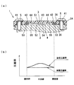
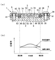
- (A) is sectional drawing which showed the valve apparatus which pinched
- (b) is explanatory drawing which showed the set compression rate of a gasket, and the compression rate after cover elastic deformation (actual) (Example 1).
- (A) is sectional drawing which showed the valve
- (b) is explanatory drawing which showed the set compression rate of a gasket, and the compression rate after cover elastic deformation (actual) (comparative example 1).
- (A) is sectional drawing which showed the valve apparatus which pinched
- (b) is explanatory drawing which showed the set compression rate of the gasket and the compression rate after cover elastic deformation (actual)
- (c) is the principal part (Example 2) which is detail expanded sectional drawing of these.
- (A) is sectional drawing which showed the valve apparatus which pinched
- (b) is explanatory drawing which showed the set compression rate of a gasket and the compression rate after cover elastic deformation (actual) (Example 3).
- (A) is sectional drawing which showed the valve apparatus which pinched
- (b) is explanatory drawing which showed the set compression rate of the gasket and the compression rate after cover elastic deformation (actual)
- (c) is the principal part (Example 4) which is detail enlarged sectional drawing of these.
- (Example 5) which is sectional drawing which showed the valve apparatus which pinched
- (A), (b) is the side view which showed the gasket, and a top view (Example 5).
- (A) is sectional drawing which showed the valve apparatus which pinched
- (b) is explanatory drawing which showed the set compression rate of a gasket, and the compression rate after cover elastic deformation (actual) (Example 6).
- Example 7 which was the top view which showed the example which has arrange
- FIG. 16 is a sectional view taken along line XVI-XVI in FIG. 15 (Example 7).
- Example 8) which was the top view which showed the example which has arrange
- FIG. 18 is a sectional view taken along line XVIII-XVIII in FIG. 17 (Example 8).
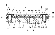
- the valve device 1 includes a body 2, a cover 3, a gasket 4, a screw 5, a valve 6, a shaft 7, a spring 8, a motor 9, gears 11 to 13, and a sensor 14.
- Body 2 has a built-in valve 6.
- the body 2 has an EGR channel 21, a motor storage chamber 22, and a gear storage chamber 23.
- the EGR channel 21 communicates the exhaust passage and the intake passage of the engine, and EGR gas flows inside.
- a part of the EGR channel 21 is formed in a cylindrical nozzle 24 that is press-fitted into the body 2.
- the motor accommodating chamber 22 is provided in a different part from the EGR flow path 21 and accommodates the motor 9.
- the motor housing chamber 22 communicates with the gear housing chamber 23.
- the gear accommodating chamber 23 accommodates the gears 11 to 13.
- the body 2 is formed with a plurality of female screw holes 25 into which the screws 5 are screwed.
- the body 2 is assembled with a cover 3 that closes the opening of the gear housing chamber 23.
- the gear housing chamber 23 is a space formed between the cover 3 and the body 2 when the cover 3 closes the opening, and is formed so as to be isolated from the external space.
- An annular first facing surface 26 is formed on the opening periphery of the body 2.
- the cover 3 holds the sensor 14 and is laminated on the body 2.
- the cover 3 is provided with an external connection connector 31 for connecting the motor 9 and the sensor 14 to an external circuit.
- an insertion hole 32 through which the shaft portion of the screw 5 passes is formed in the cover 3.
- a reinforcing metal collar 33 into which the shaft portion of the screw 5 can be inserted is fitted into the insertion hole 32.
- the cover 3 has a flange 34 protruding outward.
- the flange 34 is formed with an annular second facing surface 35 that faces the first facing surface 26 of the body 2 with a predetermined gap.
- the cover 3 includes a recess 36 for forming the gear housing chamber 23 between the cover 3 and the body 2.
- the gasket 4 is sandwiched between two parts of the body 2 and the cover 3, and seals the gap between the first facing surface 26 and the second facing surface 35 (hereinafter may be referred to as a seal).
- the gasket 4 includes a plurality of fixing portions 42, a plurality of central portions 43, and the like.
- the gasket 4 is compressed at a predetermined compression rate in the stacking direction of the body 2 and the cover 3.
- the stacking direction is the same as the compression direction of the gasket 4.
- the compression rate of the gasket 4 in the stacking direction may be referred to as the compression rate of the gasket 4 in the compression direction.
- the thickness of the gasket 4 in the stacking direction may be referred to as the thickness of the gasket 4 in the compression direction.
- the compression rate of the gasket 4 is as follows: It is calculated by the following formula.
- Compression rate (%) ((Ta ⁇ Tb) / Ta) ⁇ 100 Details of the gasket 4 will be described later.
- the valve 6 has a shaft 7 extending in the axial direction thereof.
- the valve 6 reciprocates in the rotation direction around the rotation axis (hereinafter sometimes referred to as rotation).
- the valve 6 opens and closes the EGR flow path 21.
- a seal ring groove 47 is formed on the outer periphery of the valve 6.
- the seal ring groove 47 is fitted with a seal ring 48 that seals a gap with the inner peripheral surface of the nozzle 24 when the valve 6 is closed.
- the shaft 7 is connected to the valve 6 so as to be rotatable together.
- the shaft 7 is rotatably supported with respect to the body 2 via a bearing 49 or the like.
- the electric actuator that rotationally drives the valve 6 and the shaft 7 adopts a well-known configuration.
- this electric actuator is configured by combining a spring 8, a motor 9, gears 11 to 13, a sensor 14, and the like.
- the spring 8 is assembled between the body 2 and the gear 13.
- the spring 8 biases the valve 6, the shaft 7, and the gear 13 toward the side where the valve 6 is closed (so-called valve closing direction).
- the motor 9 changes electric power into rotational torque, and is housed in the motor housing chamber 22 of the body 2.
- the plurality of gears 11 to 13 constitute a reduction mechanism that reduces the rotational output of the motor 9 and increases the driving force of the shaft. These gears 11 to 13 are housed in the gear housing chamber 23 of the body 2. The plurality of gears 11 to 13 constitute a power transmission mechanism that transmits the rotational power of the motor 9 to the valve 6.
- the gear 11 is a pinion gear that rotates integrally with the output shaft of the motor 9 and transmits the rotational output of the motor 9 to the gear 12.
- the gear 12 is an intermediate gear that transmits the rotational output of the motor 9 to the gear 13, and has a large-diameter gear tooth that meshes with the gear 11 and a small-diameter gear tooth that meshes with the gear 13.
- the gear 13 is an output gear that rotates integrally with the shaft 7 and transmits the rotational output of the motor 9 to the shaft 7.
- the sensor 14 is a non-contact type valve opening sensor that detects the rotation angle of the shaft 7, that is, the operating angle of the valve 6. This sensor 14 is fixed to the cover 3. The sensor 14 detects the operating angle of the valve 6 in accordance with the change in magnetic flux density from the magnet 15 fixed to the gear 13.
- the material of the body 2 is an aluminum-based metal.
- a receiving surface 51 that is in elastic contact with the compression surface of the gasket 4 is provided on the first facing surface 26 of the body 2.
- the receiving surface 51 has an annular shape corresponding to the shape of the gasket 4.
- the receiving surface 51 has a width that is slightly wider than the dimension in the width direction perpendicular to the compression direction of the gasket 4 and the circumferential direction of the gasket 4.
- the receiving surface 51 is formed so as to surround the periphery of the gear housing chamber 23.
- the receiving surface 51 has a uniform planar shape as shown in FIG.
- the material of the cover 3 is a synthetic resin.
- an annular gasket groove 52 in which the gasket 4 is disposed is formed on the second facing surface 35 of the cover 3.
- the gasket groove 52 is provided with a fixed portion side bottom surface 53 that elastically contacts the compression surface of the fixed portion 42 and a central portion side bottom surface 54 that elastically contacts the compression surface of the central portion 43.
- the fixed portion side bottom surface 53 is a bottom surface of the gasket groove 52 facing the compression surface of the fixed portion 42.
- the center side bottom surface 54 is the bottom surface of the gasket groove 52 facing the compression surface of the center portion 43. As shown in FIG. 2, the central portion side bottom surface 54 is shallower than the fixed portion side bottom surface 53. That is, the center-side bottom surface 54 is a cover-side convex portion that protrudes more convexly toward the body side in the stacking direction than the fixed portion-side bottom surface 53.
- the fixed portion side bottom surface 53 and the central portion side bottom surface 54 are connected by an inclined surface (slope) 55 that is in elastic contact with the compression surface of the coupling portion 44 of the gasket 4.
- the slope 55 is the bottom surface of the gasket groove 52 that faces the compression surface of the connecting portion 44 of the gasket 4. Further, the slope 55 is provided so as to gradually become deeper from the central portion side bottom surface 54 toward the fixed portion side bottom surface 53.
- the material of the gasket 4 is a rubber-like elastic body that is compressed at least in the stacking direction of the body 2 and the cover 3.
- the gasket 4 is integrally formed of a rubber-like elastic body.
- the gasket 4 is not particularly limited as long as it has elasticity within a predetermined elastic range.
- synthetic rubber such as ethylene propylene diene rubber (EPDM), hydrogen-containing nitrile rubber (H-NBR), silicone rubber, fluorine rubber (FPM), or natural rubber can be used.
- EPDM ethylene propylene diene rubber
- H-NBR hydrogen-containing nitrile rubber
- FPM fluorine rubber
- a thermoplastic elastomer in which polypropylene (PP) and EPDM are mixed can be used.
- the outer shape and the cross-sectional shape of the gasket 4 can be arbitrarily changed corresponding to the shape (space shape) of the gear housing chamber 23.
- the gasket 4 is formed in an annular shape seamlessly in the circumferential direction.
- the thickness of the gasket 4 in the stacking direction (hereinafter also referred to as the compression direction) is constant in the circumferential direction of the gasket 4.
- the compression surface is provided in both surfaces of the compression direction of the gasket 4, respectively.
- the gasket 4 is inserted in the gasket groove 52 before being sandwiched between the body 2 and the cover 3, and the thickness of the gasket 4 in the compression direction is larger than the groove depth of the gasket groove 52.
- the gasket 4 is accommodated in the gasket groove 52 in a state where the compression surface on the body side protrudes from the gasket groove 52.
- the gap between the body 2 and the cover 3 is hermetically sealed.
- the gasket 4 includes a fixing portion 42 that is disposed in the immediate vicinity of the fixing point 41, a central portion 43 that is disposed between the fixing portions 42, and a connecting portion 44 that connects the fixing portion 42 and the central portion 43. Yes.
- the fixing point 41 is a part where the female screw hole 25 or the insertion hole 32 is formed, and is a part where the cover 3 is fixed to the body 2 by the screw 5.
- the fixing part 42 is a part closest to the fixing point 41 in the gasket 4 as shown in FIG. Specifically, the fixing portions 42 are disposed in the immediate vicinity of the fixing points 41 corresponding to the plurality of screws 5, respectively.
- the plurality of fixing portions 42 are sandwiched between two parts of the body 2 and the cover 3 to seal a gap between the receiving surface 51 and the fixing portion side bottom surface 53.
- a cover-side compression surface that is in close contact with the fixed-unit-side bottom surface 53 is formed on one end surface of the fixing portion 42 in the compression direction (the upper end surface shown in FIG. 2).
- a compression surface on the body side that is in close contact with the receiving surface 51 is formed on the other end surface in the compression direction of the fixing portion 42 (the lower end surface shown in FIG. 2).
- the plurality of central portions 43 are respectively disposed between two adjacent fixed portions 42 among the plurality of fixed portions 42.
- the plurality of central portions 43 are sandwiched between two parts of the body 2 and the cover 3 to seal a gap between the receiving surface 51 and the central portion side bottom surface 54.
- a cover-side compression surface that is in close contact with the center-side bottom surface 54 is formed on one end surface of the center portion 43 in the compression direction (the upper end surface shown in FIG. 2).
- a compression surface on the body side that is in close contact with the receiving surface 51 is formed on the other end surface in the compression direction of the central portion 43 (the lower end surface shown in FIG. 2).
- the central portion 43 is a central portion where the elastic repulsive force of the gasket 4 or the elastic deformation in the stacking direction of the cover 3 caused by a temperature change is larger than that of the fixed portion side bottom surface 53. It is a portion that is in elastic contact with the side bottom surface 54.
- the elastic deformation in the stacking direction of the cover 3 is an elastic deformation in which a gap between the body 2 and the cover 3 spreads in the stacking direction.
- the annular gasket 4 is manufactured by a method of slicing a molded body (rubber-like elastic body) molded into a cylindrical shape with a predetermined thickness.
- the set compression ratio in the compression direction of the gasket 4 is set so that the central portion 43 is larger than the fixed portion 42 as shown in FIG.
- the center side bottom surface 54 of the cover 3 is shallower than the fixed portion side bottom surface 53.
- the protruding amount of the gasket 4 from the gasket groove 52 is larger in the central portion 43 than in the fixed portion 42.
- the set compression rate is the compression rate of the fixed portion 42 and the central portion 43 when the body 2 and the cover 3 in the state before assembly are assembled while maintaining the shape before assembly. For this reason, the gasket 4 has a different set compression rate in the circumferential direction.
- the compression rate set for the fixed portion 42 is the compression thickness when the thickness of the fixed portion 42 before being sandwiched between the body 2 and the cover 3 is sandwiched between the body 2 and the cover 3.
- the reduced thickness of the fixed portion 42 in the compression direction is t1
- the reduced thickness t1 indicates the difference between the thickness T1 in the compression direction of the fixing portion 42 before compression and the thickness in the compression direction of the fixing portion 42 after compression.
- the compression ratio set for the central portion 43 is determined by compressing the thickness in the compression direction of the central portion 43 before being sandwiched between the body 2 and the cover 3 when T2 is sandwiched between the body 2 and the cover 3.
- the thickness of the reduced central portion 43 in the compression direction is t2
- the following formula 2 is satisfied.
- the reduced thickness t2 indicates the difference between the thickness T2 in the compression direction of the central portion 43 before compression and the thickness in the compression direction of the central portion 43 after compression.
- FIG.8 (a) shows the valve apparatus 101 of a comparative example.
- an annular gasket 104 is sandwiched between two parts, a body 102 and a cover 103, so that the gasket 104 is compressed in the stacking direction.
- the cover 103 is provided with an annular gasket groove 110.
- the gasket 104 is provided with a fixing portion 112 disposed in the immediate vicinity of a fixing point 111 where the body 102 and the cover 103 are fastened and fixed by the screw 105.
- the cover 103 made of synthetic resin is elastically deformed by the pressure fluctuation in the gear housing chamber 23 due to the elastic repulsive force of the gasket 104 and the temperature change, and in the stacking direction between the two parts of the body 102 and the cover 103.
- the gap widens.
- the compression rate in the stacking direction of the gaskets 4, that is, the set compression rate of the gaskets 4 is set so that the central portion 43 is larger than the fixed portion 42.
- the compression ratio in the central portion 43 is, for example, a compression ratio that can maintain waterproof performance for the gear housing chamber 23, that is, in the fixed portion 42. It can prevent lowering than the compression rate.
- the number of the screws 5, the fixing points 41, and the fixing portions 42 can be reduced from, for example, six to four, it is possible to reduce the cost associated with the reduction in the number of parts and the assembling man-hours in the valve device 1. it can.
- the protruding amount of the gasket 4 from the gasket groove 52 is larger in the central portion 43 than in the fixed portion 42. Therefore, even when a lateral force perpendicular to the stacking direction is applied to the gasket 4 due to expansion and contraction of the high-pressure washing water or the gear housing chamber 23, or when the gasket 4 itself swells, the gasket 4 remains in the gasket groove.
- the assembly position of the gasket 4 is maintained at an appropriate position. Thereby, it is possible to prevent the gasket 4 from dropping from an appropriate position between the body 2 and the cover 4.
- both surfaces (compression surfaces) in the compression direction of the gasket 4 may be planar.
- a manufacturing method is adopted in which a cylindrical rubber-like elastic body is sliced with a predetermined thickness to obtain an annular gasket 4.
- the body 2 is provided with a receiving surface 51 to which the compression surface of the gasket 4 is in close contact. Since the shape of only the bottom surface 54 at the center of the gasket groove 52 is changed, the receiving surface 51 can be set to a uniform planar shape, so that the receiving surface 51 can be easily formed by molding or processing.
- the cover 3 is made of synthetic resin. Therefore, since the slope 55 can be formed by molding synthetic resin, the surface roughness of the slope 55 is improved. For this reason, since the adhesiveness of the gasket 4 with respect to the slope 55 improves, the waterproof performance with respect to the water from the outside can be improved.
- the rigidity of the cover 3 can be expected to be increased.
- FIG. 9 shows a second embodiment to which the present disclosure is applied.
- An annular gasket groove 61 in which the gasket 4 is disposed is formed on the first facing surface 26 of the body 2 of the present embodiment.
- the gasket groove 61 is provided with a bottom surface 62 that is in elastic contact with the compression surface of the gasket 4.
- the bottom surface 62 has an annular shape corresponding to the shape of the gasket 4.
- the bottom surface 62 has a width that is slightly wider than the dimension in the width direction perpendicular to the compression direction of the gasket 4 and the circumferential direction of the gasket 4.
- the bottom surface 62 is formed so as to surround the periphery of the gear housing chamber 23.
- the bottom surface 62 has a uniform planar shape as shown in FIG.
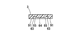
- the second facing surface 35 of the cover 3 is provided with a fixed portion receiving surface 63 that elastically contacts the compressed surface of the fixed portion 42 and a central portion receiving surface 64 that elastically contacts the compressed surface of the central portion 43. .
- the center receiving surface 64 protrudes in a convex shape toward the body side in the stacking direction from the fixed portion receiving surface 63.
- the fixed portion receiving surface 63 and the central portion receiving surface 64 are connected by a slope 65 that elastically contacts the compression surface of the connecting portion 44.
- the slope 65 is provided so as to gradually become deeper from the central receiving surface 64 toward the fixed receiving surface 63.
- the annular gasket 4 is manufactured by a method of slicing a rubber-like elastic body molded into a cylindrical shape with a predetermined thickness, as in the first embodiment.
- valve device 1 of the present embodiment has the same effects as those of the first embodiment.
- center receiving surface 64 of the cover 3 protrudes in a convex shape on the body side in the stacking direction from the fixed portion receiving surface 63. Therefore, it is sufficient that both surfaces (compression surfaces) in the compression direction of the gasket 4 are planar.
- a manufacturing method is adopted in which a cylindrical rubber-like elastic body is sliced with a predetermined thickness to obtain an annular gasket 4.
- FIG. 10 illustrates a third embodiment to which the present disclosure is applied.
- a receiving surface 66 that elastically contacts the compression surface of the gasket 4 is provided on the second facing surface 35 of the cover 3 of the present embodiment.
- the receiving surface 66 has a uniform planar shape as shown in FIG.
- a gasket groove 71 in which the gasket 4 is disposed is formed on the first facing surface 26 of the body 2.
- the gasket groove 71 is provided with a fixed portion side bottom surface 72 that elastically contacts the compression surface of the fixed portion 42 and a central portion side bottom surface 73 that elastically contacts the compression surface of the central portion 43.
- the fixed portion side bottom surface 72 is a bottom surface of the gasket groove 71 facing the compression surface of the fixed portion 42.
- the center side bottom surface 73 is a bottom surface of the gasket groove 71 facing the compression surface of the center portion 43.
- the central portion side bottom surface 73 is shallower than the fixed portion side bottom surface 72. That is, the center-side bottom surface 73 is a body-side convex portion that protrudes more convexly toward the cover side in the stacking direction than the fixed portion-side bottom surface 72.
- the fixed portion side bottom surface 72 and the central portion side bottom surface 73 are connected by a slope 74 that elastically contacts the compression surface of the connecting portion 44.
- the slope 74 is the bottom surface of the gasket groove 71 that faces the compression surface of the connecting portion 44.
- the slope 74 is provided so as to gradually become deeper from the center side bottom surface 73 toward the fixed portion side bottom surface 72.
- the annular gasket 4 is manufactured by a method of slicing a rubber-like elastic body molded into a cylindrical shape with a predetermined thickness, as in the first embodiment.
- valve device 1 of the present embodiment has the same effects as those of the first and second embodiments.
- the central portion side bottom surface 73 of the gasket groove 71 is shallower than the fixed portion side bottom surface 72.
- a manufacturing method is adopted in which a cylindrical rubber-like elastic body is sliced with a predetermined thickness to obtain an annular gasket 4.
- the receiving surface 66 of the cover 3 can be set to a uniform plane shape, the receiving surface 66 can be easily formed by either resin molding or cutting.
- the material of the body 2 is metal.
- the metal body 2 is more rigid than the synthetic resin cover 3, and thus is less susceptible to expansion and contraction in the gear housing chamber 23. For this reason, since it is not necessary to consider the height of the center side bottom surface 73 and the slope 74 in view of the elastic deformation of the body 2, the number of trials and errors in designing the shape of the body 2 is reduced. Therefore, the slope 74 can be easily set for the gasket groove 71 of the body 2.
- FIG. 11 illustrates a fourth embodiment to which the present disclosure is applied.
- An annular gasket groove 67 in which the gasket 4 is disposed is formed in the second facing surface 35 of the cover 3 of the present embodiment.
- the gasket groove 67 is provided with a bottom surface 68 that elastically contacts the compression surface of the gasket 4.
- the bottom surface 68 has an annular shape corresponding to the shape of the gasket 4.
- the bottom surface 68 has a width that is slightly wider than the dimension in the width direction perpendicular to the compression direction of the gasket 4 and the circumferential direction of the gasket 4.
- the bottom surface 68 has a uniform planar shape as shown in FIG.
- the first opposing surface 26 of the body 2 is provided with a fixed portion receiving surface 75 that elastically contacts the compression surface of the fixed portion 42 and a central portion receiving surface 76 that elastically contacts the compression surface of the central portion 43. .
- the center receiving surface 76 protrudes in a convex shape toward the cover side in the stacking direction from the fixed portion receiving surface 75. Further, the fixed portion receiving surface 75 and the central portion receiving surface 76 are connected by a slope 77 that elastically contacts the compression surface of the connecting portion 44. The slope 77 is provided so as to gradually become deeper from the center receiving surface 76 toward the fixed portion receiving surface 75. Thereby, the set compression rate of the gasket 4 is set so that the center portion 43 is larger than the fixed portion 42 as shown in FIG.
- the annular gasket 4 is manufactured by a method of slicing a molded body (rubber-like elastic body) molded into a cylindrical shape with a predetermined thickness, as in the first embodiment.
- valve device 1 of the present embodiment has the same effects as those of the first to third embodiments.
- center receiving surface 76 of the body 2 protrudes in a convex shape toward the cover side in the stacking direction from the fixed portion receiving surface 75. Therefore, it is sufficient that both surfaces (compression surfaces) in the compression direction of the gasket 4 are planar.
- a plurality of annular gaskets 4 can be created by employing the manufacturing method described above. Thereby, since a plurality of annular gaskets 4 can be formed from at least one rubber-like elastic body by slicing the cylindrical rubber-like elastic body multiple times with a predetermined thickness, the manufacturing cost can be suppressed.
- a receiving surface 51 is provided on the first facing surface 26 of the body 2 of the present embodiment.
- a gasket groove 67 is formed on the second facing surface 35 of the cover 3.
- a bottom surface 68 is provided in the gasket groove 67.
- the thickness of the gasket 4 in the stacking direction is thicker in the central portion 43 than in the fixed portion 42. Accordingly, the set compression rate of the gasket 4 is set so that the central portion 43 is larger than the fixed portion 42.
- valve device 1 of this embodiment has the same effects as those of the first to fourth embodiments.
- the thickness of the gasket 4 in the stacking direction is thicker in the central portion 43 than in the fixed portion 42.
- the shape of the receiving surface 51 and the bottom surface 68 that are in close contact with the compression surface of the central portion 43 is changed (for example, the thickness is increased). Even if the internal pressure of the storage chamber 23 rises, the cover 3 made of synthetic resin becomes difficult to elastically deform, and the cover 3 may be cracked.
- FIG. 14 shows a sixth embodiment to which the present disclosure is applied.
- the gasket groove 71 formed on the body 2 side is provided with a fixed portion side bottom surface 72 and a central portion side bottom surface 73. Further, a slope 74 is connected between the fixed portion side bottom surface 72 and the central portion side bottom surface 73.
- the gasket groove 52 formed on the cover 3 side is provided with a fixed portion side bottom surface 53, a central portion side bottom surface 54, and a slope 55.
- gasket grooves 71 and 52 are formed on both sides of the body 2 and the cover 3, and the gasket groove 71 formed on the body 2 side and the gasket groove 52 formed on the cover 3 side Are combined to form a groove in which the gasket 4 is provided.
- center part side bottom face 73 is shallower than the fixed part side bottom face 72, as shown to Fig.14 (a).
- the center part side bottom face 54 is shallower than the fixed part side bottom face 53 as shown in FIG. Accordingly, the set compression rate of the gasket 4 is set so that the central portion 43 is larger than the fixed portion 42 as shown in FIG.
- valve device 1 of the present embodiment provides the same effects as those of the first to fifth embodiments.
- Example 7 15 and 16 illustrate a seventh embodiment to which the present disclosure is applied.
- the same reference numerals as in the first to sixth embodiments indicate the same configuration or function, and a description thereof will be omitted.
- the body 2 and the cover 3 of this embodiment adopt a structure that does not have a gasket groove.
- the first opposing surface 26 of the body 2 is provided with a receiving surface (not shown) that is in elastic contact with the compression surface of the gasket 4.
- the body 2 and the cover 3 are provided with a plurality of cylindrical pins 91 that define the height of the gasket 4 in the compression direction. Also, illustration of the pins on the body side is omitted.
- the body side pin and the cover side pin 91 are provided so as to contact each other.
- the body 2 may be provided with a planar wall that contacts the pin 91 instead of the pin.
- a fixed portion receiving surface 63, a central portion receiving surface 64, and a slope 65 are provided on the second facing surface 35 of the cover 3.
- the center receiving surface 64 protrudes in a convex shape toward the body in the stacking direction from the fixed portion receiving surface 63. That is, the cover 3 is provided with a convex center receiving surface 64 that elastically contacts the abutting surface of the intermediate path in the circumferential direction of the gasket 4. Accordingly, the set compression rate of the gasket 4 is set so that the central portion 43 is larger than the fixed portion 42.
- valve device 1 of the present embodiment has the same effects as those of the first to sixth embodiments.
- the body 2 and the cover 3 of the present embodiment adopt a structure that does not have a gasket groove, as in the seventh embodiment.
- the first opposing surface 26 of the body 2 is provided with a receiving surface (not shown) that is in elastic contact with the compression surface of the gasket 4 as in the seventh embodiment.
- the body 2 and the cover 3 are provided with a plurality of arc-shaped walls 92 that define the height of the gasket 4 in the compression direction. Note that illustration of the wall on the body side is omitted.
- the cover 3 is provided with a convex center receiving surface 64 that elastically contacts the contact surface of the intermediate path in the circumferential direction of the gasket 4. Accordingly, the set compression rate of the gasket 4 is set so that the central portion 43 is larger than the fixed portion 42.
- valve device 1 of the present embodiment has the same effects as those of the first to seventh embodiments.
- the valve device of the present disclosure is applied to a valve device (so-called EGR valve device) 1 that controls the flow rate of EGR gas.
- the valve device of the present disclosure is used as a flow rate of intake air to the internal combustion engine. You may apply to the valve apparatus (what is called a throttle valve apparatus) which performs control.
- the valve device of the present disclosure is used as a valve device (so-called cooling water control valve device) that performs flow rate control (flow channel opening / closing and opening degree adjustment) or distribution control (flow channel switching) of an internal combustion engine. It may be applied.
- an elastic body mainly composed of synthetic rubber such as EPDM is adopted as the material of the gasket, but an elastic body mainly composed of natural rubber or thermoplastic elastomer may be employed as the material of the gasket.
- the cover 3 is fixed to the body 2 with a plurality of fixing points 41 using the screw 5, but the cover 3 is fixed to the body 2 with a plurality of fixing points 41 using a clamp. May be. Further, the cover 3 may be fixed to the body 2 at a plurality of fixing points 41 using caulking connection or snap-fit connection. Alternatively, the cover 3 may be fixed to the body 2 at a plurality of fixing points 41 using spot welding or spot welding.
- the elastic deformation of the body 2 due to the elastic repulsive force of the gasket 4 or heat is applied to the central portion 43 of the gasket 4 from the fixed portion receiving surface 75. It is good also as a site
- the fixed portion side bottom surface 53 and the central portion side bottom surface 54 may be connected by a smooth curved bottom surface.
- the fixed portion receiving surface 63 and the central portion receiving surface 64 may be connected by a smooth curved bottom surface.
- the fixed portion side bottom surface 72 and the central portion side bottom surface 73 may be connected by a smooth curved bottom surface.
- the fixed portion receiving surface 75 and the central portion receiving surface 76 may be connected by a smooth curved bottom surface.
- a place other than the fixed part 42 may be used as the central part 43.
- the connecting portion 44 may be included in the central portion 43.
- the connecting portion connecting the adjacent fixed portions 42 and the fixed portions 42 is non-linear
- the line orthogonal to the midpoint of the straight line connecting the adjacent fixed portions 42 and the fixed portions 42, and the gasket 4 May be defined as the central portion 43.
- an intermediate point from the adjacent fixed portion 42 to the fixed portion 42 is set on the intermediate path in the circumferential direction of the gasket 4.
- the central portion 43 may be defined.
- the central portion 43 is defined as a point where the difference in distortion between the body 2 and the cover 3, that is, the difference in the deformation amount between the body 2 and the cover 3 is maximized. May be.
- the distance between the two adjacent fixing points 41 is relatively longer than the short direction, and the longitudinal direction of the gasket 4 (the vertical direction shown in FIG. 4) and the two adjacent fixing points.
- the compression ratio in the stacking direction of the gasket 4 is set to be more central than the fixed portion 42 in both the short direction of the gasket 4 (the left-right direction shown in FIG. 4), where the distance between 41 is relatively shorter than the longitudinal direction. 43 is larger. Further, the compression rate in the stacking direction only in the longitudinal direction of the gasket 4 may be larger in the central portion 43 than in the fixed portion 42.
- the gasket grooves 52, 61, 67, and 71 are surrounded by the outer side of the gasket grooves 52, 61, 67, and 71 on the first facing surface 26 of the body 2.
- a circumferential groove (concave portion) extending in the circumferential direction of the gasket grooves 52, 61, 67, 71 is provided, and a portion of the second facing surface 35 of the cover 3 on the outer side than the gasket grooves 52, 61, 67, 71 is provided.
- You may comprise the maze structure for improving the waterproof performance with respect to the water W from the outside by providing the convex part (projection) which enters in a surrounding groove.
- the gasket grooves 52, 61, 67, 71 are surrounded by the portion of the second facing surface 35 of the cover 3 outside the gasket grooves 52, 61, 67, 71.
- a circumferential groove (concave portion) extending in the circumferential direction of the gasket grooves 52, 61, 67, 71 is provided, and a portion of the first facing surface 26 of the body 2 on the outer side than the gasket grooves 52, 61, 67, 71 is provided.
- You may comprise the maze structure for improving the waterproof performance with respect to the water W from the outside by providing the convex part (projection) which enters in a surrounding groove.
Landscapes
- Engineering & Computer Science (AREA)
- General Engineering & Computer Science (AREA)
- Mechanical Engineering (AREA)
- Chemical & Material Sciences (AREA)
- Combustion & Propulsion (AREA)
- Physics & Mathematics (AREA)
- Geometry (AREA)
- Gasket Seals (AREA)
- Electrically Driven Valve-Operating Means (AREA)
- Valve Housings (AREA)
Abstract
バルブ装置(1)は、ガスケット(4)の積層方向の圧縮率、つまりガスケット(4)の設定圧縮率を、固定部(42)よりも中央部(43)の方が大きくなるように設定している。このように設定圧縮率を設定するため、カバー(3)の中央部側底面(54)を固定部側底面(53)よりも浅くしている。これによって、ガスケット(4)の中央部(43)の圧縮率が、固定部(42)における圧縮率よりも小さくなる現象が生じた場合でも、中央部(43)における圧縮率が、固定部(42)における圧縮率よりも低下するのを妨げることができる。したがって、ボディ(2)とカバー(3)との2部品間にガスケット(4)が挟み込まれてガスケット(4)を積層方向に圧縮したときの弾性反発力によって外部からの水に対する防水性能を確保することができる。
Description
本願は、2016年5月24日に出願された日本国特許出願第2016-103042号に基づくものであり、この開示をもってその内容を本明細書中に開示したものとする。
本開示は、複数のギヤを収容する収容室の内部への防水を環状のガスケットを使用して行うバルブ装置に関するものである。
従来より、内燃機関(以下、エンジンと呼ぶ)から排出された排気ガスの一部であるEGRガスの流量を調整するバルブ装置が提案されている(例えば、特許文献1参照)。
バルブ装置は、バルブを内蔵するボディに、モータの回転出力をバルブに伝達する複数のギヤを収容する収容室を設けている。この収容室の開口部は、カバーによって塞がれている。
カバーは、ボディの端面との間に環状のガスケットを挟み込んだ状態で、ボディの端面に対して複数の固定点で固定されている。カバーの端面および/またはボディの端面には、ガスケットを収容するガスケット溝が形成されている。
ガスケットは、ボディの端面とガスケット溝の底面との間を気密シールする合成ゴム製のシール材である。このガスケットは、ボディとカバーとの固定点近傍に、ボディとカバーとの間に挟み込まれる固定部を有している。
そして、バルブ装置は、ガスケットの存在により、外部から収容室への水の浸入を防いでいる。
ところが、複数の固定点のうち隣り合う固定点間の距離が比較的に長い場合、つまりガスケットの固定部から遠い位置、特に固定部間に配置される中央部では、ガスケットの圧縮に伴う弾性反発力によりカバーが弾性変形する場合がある。これにより、ガスケットの中央部の圧縮率が小さくなる。
また、高温環境下での収容室内の圧力変動によりカバーが弾性変形する場合がある。これにより、ガスケットの中央部の圧縮率が小さくなる。
したがって、ガスケットの中央部では、固定部と比べると気密シール性が低下するため、外部からの水、例えば高圧洗浄水や雨水等に対する防水性能が低下するという問題がある。
本開示は、上記問題点に鑑みて成されたものであり、その目的は、ガスケットの中央部における圧縮率が小さくなっても、外部からの水に対する防水性能を確保することにある。
本開示の態様によれば、ボディとカバーとが固定される部位を固定点としたとき、ガスケットは、少なくともボディとカバーとの積層方向に圧縮される弾性体であり、固定点の直近に配置される複数の固定部、およびこれらの固定部間に配置される中央部を有している。
ガスケットの積層方向の圧縮率は、固定部よりも中央部の方が大きい。
これによって、ガスケットの中央部における圧縮率が小さくなる現象が生じた場合でも、中央部における圧縮率が、例えば収容室に対する防水性能を維持可能な圧縮率よりも低下するのを妨げることができる。
したがって、ガスケットの中央部における圧縮率が小さくなっても、ボディとカバーとの間にガスケットが挟み込まれてガスケットを圧縮したときの弾性反発力によって外部からの水に対する防水性能を確保することができる。この結果、外部から収容室の内部への水の浸入を阻止することができる。
本開示についての上記目的およびその他の目的、特徴や利点は、添付の図面を参照しながら下記の詳細な記述により、より明確になる。
以下、図面を参照しながら、本開示の実施例を説明する。
[実施例1の構成]
図1ないし図7は、本開示を適用した実施例1を示したものである。
図1ないし図7は、本開示を適用した実施例1を示したものである。
本実施例のバルブ装置1は、ボディ2、カバー3、ガスケット4、スクリュー5、バルブ6、シャフト7、スプリング8、モータ9、ギヤ11~13およびセンサ14を備えている。
ボディ2は、バルブ6を内蔵する。このボディ2は、EGR流路21、モータ収容室22およびギヤ収容室23を有している。
EGR流路21は、エンジンの排気通路と吸気通路とを連通し、内部をEGRガスが流れる。このEGR流路21の一部は、ボディ2に圧入される円筒状のノズル24内に形成されている。
モータ収容室22は、EGR流路21とは異なる部位に設けられて、モータ9を収容している。このモータ収容室22は、ギヤ収容室23と連通している。
ギヤ収容室23は、ギヤ11~13を収容している。
また、ボディ2には、スクリュー5がねじ込まれる複数の雌螺子孔25が形成されている。また、ボディ2には、ギヤ収容室23の開口部を塞ぐカバー3が組み付けられている。ギヤ収容室23は、開口部をカバー3が塞ぐことでカバー3とボディ2との間に形成される空間であり、外部の空間から隔離するように形成されている。また、ボディ2の開口周縁には、環状の第1対向面26が形成されている。
なお、ボディ2の詳細は、後述する。
カバー3は、センサ14を保持し、ボディ2に積層されている。このカバー3には、モータ9およびセンサ14と外部回路との接続を行う外部接続用コネクタ31が設けられている。また、カバー3には、スクリュー5の軸部が貫通する挿通孔32が形成されている。この挿通孔32の内部には、スクリュー5の軸部が挿通可能な補強用の金属カラー33が嵌め込まれている。
カバー3は、外部に向かって突出したフランジ34を有している。このフランジ34には、ボディ2の第1対向面26と所定の隙間を隔てて対向する環状の第2対向面35が形成されている。また、カバー3は、ボディ2との間にギヤ収容室23を形成するための凹部36を備えている。
なお、カバー3の詳細は、後述する。
ガスケット4は、ボディ2とカバー3との2部品間に挟み込まれて、第1対向面26と第2対向面35との間の隙間を密封(以下、シールと呼ぶ場合がある)する。
このガスケット4は、複数の固定部42および複数の中央部43等を備えている。
また、ガスケット4は、ボディ2とカバー3との積層方向に所定の圧縮率で圧縮される。また、積層方向は、ガスケット4の圧縮方向と同一方向である。このため、ガスケット4の積層方向の圧縮率を、ガスケット4の圧縮方向の圧縮率と呼ぶ場合がある。また、ガスケット4の積層方向の厚みを、ガスケット4の圧縮方向の厚みと呼ぶ場合がある。ここで、圧縮前の自由状態にあるガスケット4の積層方向における厚さをTaとし、圧縮された状態にあるガスケット4の積層方向における厚さをTbとした場合、ガスケット4の圧縮率は、以下の数式によって求められる。圧縮前のガスケット4の厚さTaと、圧縮後のガスケット4の厚さTbとの差は、圧縮によって減少したガスケット4の厚さである。
圧縮率(%)=((Ta-Tb)/Ta)×100
なお、ガスケット4の詳細は、後述する。
圧縮率(%)=((Ta-Tb)/Ta)×100
なお、ガスケット4の詳細は、後述する。
バルブ6は、その軸方向に延びるシャフト7を有している。このバルブ6は、回転軸を中心にして回転方向に往復移動(以下、回動と呼ぶ場合がある)する。
バルブ6は、EGR流路21を開閉するものである。このバルブ6の外周には、シールリング溝47が形成されている。このシールリング溝47には、バルブ6の閉弁時にノズル24の内周面との間の隙間を密閉するシールリング48が嵌め込まれている。
シャフト7は、バルブ6と一体回転可能に連結されている。このシャフト7は、ボディ2に対してベアリング49等を介して回転自在に支持されている。
バルブ6とシャフト7を回転駆動する電動アクチュエータは、周知な構成を採用するものである。この電動アクチュエータは、一例を開示すると、スプリング8、モータ9、ギヤ11~13およびセンサ14等を組み合わせて構成される。
スプリング8は、ボディ2とギヤ13との間に組み付けられている。このスプリング8は、バルブ6、シャフト7およびギヤ13を、バルブ6が閉じる側(所謂、閉弁方向)に付勢する。
モータ9は、電力を回転トルクに変化させるもので、ボディ2のモータ収容室22内に収納されている。
複数のギヤ11~13は、モータ9の回転出力を減速してシャフトの駆動力を増大させる減速機構を構成している。これらのギヤ11~13は、ボディ2のギヤ収容室23内に収納されている。また、複数のギヤ11~13は、モータ9の回転動力をバルブ6に伝える動力伝達機構を構成している。
ギヤ11は、モータ9の出力軸と一体的に回転し、モータ9の回転出力をギヤ12に伝えるピニオンギヤである。
ギヤ12は、モータ9の回転出力をギヤ13に伝える中間ギヤであって、ギヤ11と噛み合う大径ギヤ歯、およびギヤ13と噛み合う小径ギヤ歯を有している。
ギヤ13は、シャフト7と一体的に回転し、モータ9の回転出力をシャフト7に伝える出力ギヤである。
センサ14は、シャフト7の回転角度、つまりバルブ6の作動角を検出する非接触型のバルブ開度センサである。このセンサ14は、カバー3に固定されている。また、センサ14は、ギヤ13に固定されたマグネット15からの磁束密度の変化に応じてバルブ6の作動角を検出する。
[実施例1の特徴]
ボディ2の材質は、アルミニウム系金属である。このボディ2の第1対向面26には、ガスケット4の圧縮面と弾性接触する受け面51が設けられている。
ボディ2の材質は、アルミニウム系金属である。このボディ2の第1対向面26には、ガスケット4の圧縮面と弾性接触する受け面51が設けられている。
受け面51は、ガスケット4の形状に対応した環状である。この受け面51は、ガスケット4の圧縮方向およびガスケット4の周方向に対して垂直な幅方向の寸法よりも若干広い幅を有している。また、受け面51は、ギヤ収容室23の周囲を取り囲むように形成されている。
受け面51は、図2に示したように、一様平面形状となっている。
カバー3の材質は、合成樹脂である。このカバー3の第2対向面35には、図2ないし図4に示したように、ガスケット4が配置される環状のガスケット溝52が形成されている。このガスケット溝52には、固定部42の圧縮面と弾性接触する固定部側底面53、および中央部43の圧縮面と弾性接触する中央部側底面54が設けられている。
固定部側底面53は、固定部42の圧縮面に対向するガスケット溝52の底面である。
中央部側底面54は、中央部43の圧縮面に対向するガスケット溝52の底面である。この中央部側底面54は、図2に示したように、固定部側底面53よりも浅くなっている。すなわち、中央部側底面54は、固定部側底面53よりも積層方向のボディ側に凸状に突き出したカバー側凸部である。
また、固定部側底面53と中央部側底面54との間は、ガスケット4の連結部分44の圧縮面と弾性接触する斜面(スロープ)55で接続されている。このスロープ55は、ガスケット4の連結部分44の圧縮面に対向するガスケット溝52の底面である。また、スロープ55は、中央部側底面54から固定部側底面53へ向かって次第に深くなるように設けられている。
ガスケット4の材質は、少なくともボディ2とカバー3との積層方向に圧縮されるゴム状弾性体である。
ガスケット4は、ゴム状弾性体によって一体的に形成されている。このガスケット4は、所定の弾性域内で弾性を有するものであれば特に限定されない。例えばエチレンプロピレンジエンゴム(EPDM)、水素配合ニトリルゴム(H-NBR)、シリコーンゴム、フッ素ゴム(FPM)等の合成ゴムまたは天然ゴムが使用可能である。また、ポリプロピレン(PP)とEPDMを混ぜた熱可塑性エラストマーが使用可能である。
なお、ゴム状弾性体として複数種の合成ゴムや天然ゴムをブレンドしたものを使用しても良い。また、ガスケット4の外形形状や断面形状は、ギヤ収容室23の形状(空間形状)に対応して任意に変更できる。
ガスケット4は、周方向に継ぎ目なく環状に形成されている。このガスケット4の積層方向(以下、圧縮方向とも言う)の厚みは、ガスケット4の周方向で一定である。また、ガスケット4の圧縮方向の両面には、圧縮面がそれぞれ設けられている。また、ガスケット4は、ボディ2とカバー3との間に挟み込まれる前、ガスケット溝52に挿入された段階では、ガスケット4の圧縮方向の厚みがガスケット溝52の溝深さよりも大きい。これにより、ガスケット4は、ボディ側の圧縮面がガスケット溝52からはみ出した状態で、ガスケット溝52内に収容されている。また、ガスケット4は、ガスケット溝52に組み付けられた状態で、ボディ2とカバー3との間に挟み込まれると、ボディ2とカバー3との間の隙間を気密シールする。
ここで、ボディ2とカバー3との2部品がスクリュー5により締結固定される部位を固定点41と呼ぶ。そして、ガスケット4は、固定点41の直近に配置される固定部42、これらの固定部42間に配置される中央部43、および固定部42と中央部43とを繋ぐ連結部分44を備えている。
固定点41は、雌螺子孔25または挿通孔32が形成されている部位であり、スクリュー5によりボディ2に対してカバー3が固定される箇所である。
固定部42とは、図5に示したように、ガスケット4における固定点41に最も近い部位のことである。具体的には、複数のスクリュー5の各々に対応した各固定点41の直近にそれぞれ固定部42が配置される。
複数の固定部42は、ボディ2とカバー3との2部品に挟み込まれて、受け面51と固定部側底面53との間の隙間を密封している。
固定部42の圧縮方向の一端面(図2において図示上端面)には、固定部側底面53に密着するカバー側の圧縮面が形成されている。また、固定部42の圧縮方向の他端面(図2のおいて図示下端面)には、受け面51に密着するボディ側の圧縮面が形成されている。
複数の中央部43は、複数の固定部42のうち、隣接する2つの固定部42間にそれぞれ配置されている。
複数の中央部43は、ボディ2とカバー3との2部品に挟み込まれて、受け面51と中央部側底面54との間の隙間を密封している。
中央部43の圧縮方向の一端面(図2において図示上端面)には、中央部側底面54に密着するカバー側の圧縮面が形成されている。また、中央部43の圧縮方向の他端面(図2において図示下端面)には、受け面51に密着するボディ側の圧縮面が形成されている。
ここで、中央部43とは、図6に示したように、ガスケット4の弾性反発力、あるいは温度変化により発生するカバー3における積層方向の弾性変形が固定部側底面53よりも大きくなる中央部側底面54と弾性接触する部位のことである。そのカバー3における積層方向の弾性変形とは、ボディ2とカバー3との間の隙間が積層方向に広がるような弾性変形のことである。
そして、環状のガスケット4は、筒状に成型した成型体(ゴム状弾性体)を、所定の厚みでスライスするという方法によって製造されている。
ガスケット4の圧縮方向の設定圧縮率は、図7に示したように、固定部42よりも中央部43の方が大きくなるように設定されている。このように設定圧縮率を設定するため、カバー3の中央部側底面54を固定部側底面53よりも浅くしている。
これにより、ガスケット溝52からのガスケット4のはみ出し量は、固定部42よりも中央部43の方が大きくなっている。
ここで、設定圧縮率とは、組み付け前の状態のボディ2とカバー3が、組み付け前の形状を維持しながら組み付けた時の固定部42と中央部43の圧縮率のことである。このため、ガスケット4は、その周方向で設定圧縮率が異なる。
また、固定部42の設定圧縮率は、ボディ2とカバー3との間に挟み込まれる前の固定部42の圧縮方向の厚さをT1、ボディ2とカバー3との間に挟み込まれた時に圧縮されて減少した固定部42の圧縮方向の厚さをt1としたとき、下記の数1の式を満たす。ここで、減少した厚さt1とは、圧縮前の固定部42の圧縮方向の厚さT1と、圧縮後の固定部42の圧縮方向の厚さとの差を指す。
また、中央部43の設定圧縮率は、ボディ2とカバー3との間に挟み込まれる前の中央部43の圧縮方向の厚さをT2、ボディ2とカバー3との間に挟み込まれた時に圧縮されて減少した中央部43の圧縮方向の厚さをt2としたとき、下記の数2の式を満たす。ここで、減少した厚さt2とは、圧縮前の中央部43の圧縮方向の厚さT2と、圧縮後の中央部43の圧縮方向の厚さとの差を指す。
[数1]
固定部42の設定圧縮率(%)=(t1/T1)×100
[数2]
中央部43の設定圧縮率(%)=(t2/T2)×100
固定部42の設定圧縮率(%)=(t1/T1)×100
[数2]
中央部43の設定圧縮率(%)=(t2/T2)×100
[実施例1の効果]
ここで、図8(a)は比較例のバルブ装置101を示す。このバルブ装置101は、ボディ102とカバー103との2部品間に環状のガスケット104が挟み込まれてガスケット104が積層方向に圧縮されるようになっている。
ここで、図8(a)は比較例のバルブ装置101を示す。このバルブ装置101は、ボディ102とカバー103との2部品間に環状のガスケット104が挟み込まれてガスケット104が積層方向に圧縮されるようになっている。
カバー103には、環状のガスケット溝110が設けられている。
ガスケット104には、ボディ102とカバー103とがスクリュー105により締結固定される固定点111の直近に配置される固定部112が設けられている。
ところで、バルブ装置101における部品点数の減少および組付工数の低減に伴うコスト削減を狙って、スクリュー105、固定点111および固定部112の個数を例えば6個から4個に減らすことが考えられる。この場合には、隣接する固定部112間の距離が長くなると、固定部112間の中央部113の圧縮力が低下する。
具体的には、ガスケット104の弾性反発力や温度変化に伴うギヤ収容室23内の圧力変動によって合成樹脂製のカバー103が弾性変形し、ボディ102とカバー103との2部品間の積層方向の隙間が広がる。これにより、固定部112間の中央部113の圧縮力が、図8(b)に示したように、固定部112の圧縮率(=ガスケット104の設定圧縮率)よりも低下する。
したがって、ガスケット104の中央部113では、固定部112と比べると気密シール性が低下するため、高圧洗浄水や雨水等に対する防水性能が低下するという問題がある。なお、図7(b)の破線および図8(b)の破線は、ガスケット4およびガスケット104の弾性反発力や温度変化を含めた実際の圧縮率を表わしている。
そこで、本実施例のバルブ装置1においては、ガスケット4の積層方向の圧縮率、つまりガスケット4の設定圧縮率を、固定部42よりも中央部43の方が大きくなるように設定している。
これによって、ガスケット4の中央部43の圧縮率が小さくなる現象が生じた場合でも、中央部43における圧縮率が、例えばギヤ収容室23に対する防水性能を維持可能な圧縮率、つまり固定部42における圧縮率よりも低下するのを妨げることができる。
したがって、カバー3の弾性変形により、ガスケット4の中央部43における圧縮率が小さくなっても、ボディ2とカバー3との2部品間にガスケット4が挟み込まれてガスケット4を積層方向に圧縮したときの弾性反発力によって外部からの水に対する防水性能を確保することができる。この結果、スクリュー5、固定点41および固定部42を増やすことなく、外部から収容室の内部への水の浸入を阻止することができる。
また、スクリュー5、固定点41および固定部42の個数を例えば6個から4個に減らすことができるので、バルブ装置1における部品点数の減少および組付工数の低減に伴うコスト削減を図ることができる。
また、ガスケット溝52からのガスケット4のはみ出し量は、固定部42よりも中央部43の方が大きくなっている。これにより、高圧洗浄水やギヤ収容室23の膨張、収縮によって積層方向に垂直な横方向の力がガスケット4にかかった場合、もしくはガスケット4自身の膨潤が起こった場合でも、ガスケット4がガスケット溝52に配置されていることで、ガスケット4の組み付け位置が適正な位置に保たれる。これにより、ボディ2とカバー4との適正な位置からガスケット4が脱落するのを防止することができる。
また、ガスケット溝52の中央部側底面54は、固定部側底面53よりも浅くなっている。これにより、ガスケット4の材質を合成ゴムとした場合には、ガスケット4の圧縮方向の両面(圧縮面)を平面形状とすれば良い。
また、筒状のゴム状弾性体を、所定の厚みでスライスして環状のガスケット4を得るという製造方法を採用している。これにより、筒状のゴム状弾性体を、所定の厚みで複数回スライスすることで、少なくとも1つのゴム状弾性体から環状のガスケット4を複数作成できるので、製造コストを抑えることができる。
また、ボディ2には、ガスケット4の圧縮面が密着する受け面51が設けられている。そして、ガスケット溝52の中央部側底面54のみ形状が変更されるので、受け面51を一様平面形状に設定できるため、受け面51を成型でも加工でも容易に形成することができる。
また、カバー3の材質が合成樹脂である。これにより、合成樹脂の成型でスロープ55ができるため、スロープ55の面粗度が良くなる。このため、スロープ55に対するガスケット4の密着性が向上するので、外部からの水に対する防水性能を高めることができる。
また、合成樹脂製のカバー3のガスケット溝52に凸状の中央部側底面54を設けることで、カバー3の剛性アップが期待できる。
[実施例2の構成]
図9は、本開示を適用した実施例2を示したものである。
図9は、本開示を適用した実施例2を示したものである。
ここで、実施例1と同じ符号は、同一の構成または機能を示すものであって、説明を省略する。
本実施例のボディ2の第1対向面26には、ガスケット4が配置される環状のガスケット溝61が形成されている。このガスケット溝61には、ガスケット4の圧縮面と弾性接触する底面62が設けられている。
底面62は、ガスケット4の形状に対応した環状である。この底面62は、ガスケット4の圧縮方向およびガスケット4の周方向に対して垂直な幅方向の寸法よりも若干広い幅を有している。また、底面62は、ギヤ収容室23の周囲を取り囲むように形成されている。
底面62は、図9(a)に示したように、一様平面形状となっている。
また、カバー3の第2対向面35には、固定部42の圧縮面と弾性接触する固定部受け面63、および中央部43の圧縮面と弾性接触する中央部受け面64が設けられている。
中央部受け面64は、固定部受け面63よりも積層方向のボディ側に凸状に突き出している。また、固定部受け面63と中央部受け面64との間は、連結部分44の圧縮面と弾性接触するスロープ65で接続されている。このスロープ65は、中央部受け面64から固定部受け面63へ向かって次第に深くなるように設けられている。これにより、ガスケット4の設定圧縮率は、図9(b)に示したように、固定部42よりも中央部43の方が大きくなるように設定される。
そして、環状のガスケット4は、実施例1と同様に、筒状に成型したゴム状弾性体を、所定の厚みでスライスするという方法によって製造されている。
以上のように、本実施例のバルブ装置1においては、実施例1と同様な効果を奏する。
また、カバー3の中央部受け面64は、固定部受け面63よりも積層方向のボディ側に凸状に突き出している。したがって、ガスケット4の圧縮方向の両面(圧縮面)が平面形状であればこと足りる。
また、筒状のゴム状弾性体を、所定の厚みでスライスして環状のガスケット4を得るという製造方法を採用している。これにより、筒状のゴム状弾性体を、所定の厚みで複数回スライスすることで、少なくとも1つのゴム状弾性体から環状のガスケット4を複数作成できるので、製造コストを抑えることができる。
また、カバー3の中央部受け面64である凸部の箇所が、ボディ2のガスケット溝61内に入り込んだ状態とすることで、図9(c)に示すように、迷路構造となり、外部からの水Wに対する防水性能をさらに高めることができる。
[実施例3の構成]
図10は、本開示を適用した実施例3を示したものである。
図10は、本開示を適用した実施例3を示したものである。
ここで、実施例1及び2と同じ符号は、同一の構成または機能を示すものであって、説明を省略する。
本実施例のカバー3の第2対向面35には、ガスケット4の圧縮面と弾性接触する受け面66が設けられている。
受け面66は、図10(a)に示したように、一様平面形状となっている。
また、ボディ2の第1対向面26には、ガスケット4が配置されるガスケット溝71が形成されている。このガスケット溝71には、固定部42の圧縮面と弾性接触する固定部側底面72、および中央部43の圧縮面と弾性接触する中央部側底面73が設けられている。
固定部側底面72は、固定部42の圧縮面に対向するガスケット溝71の底面である。
中央部側底面73は、中央部43の圧縮面に対向するガスケット溝71の底面である。この中央部側底面73は、固定部側底面72よりも浅くなっている。すなわち、中央部側底面73は、固定部側底面72よりも積層方向のカバー側に凸状に突き出したボディ側凸部である。
また、固定部側底面72と中央部側底面73との間は、連結部分44の圧縮面と弾性接触するスロープ74で接続されている。このスロープ74は、連結部分44の圧縮面に対向するガスケット溝71の底面である。また、スロープ74は、中央部側底面73から固定部側底面72へ向かって次第に深くなるように設けられている。これにより、ガスケット4の設定圧縮率は、図10(b)に示したように、固定部42よりも中央部43の方が大きくなるように設定される。
そして、環状のガスケット4は、実施例1と同様に、筒状に成型したゴム状弾性体を、所定の厚みでスライスするという方法によって製造されている。
以上のように、本実施例のバルブ装置1においては、実施例1及び2と同様な効果を奏する。
また、ガスケット溝71の中央部側底面73は、固定部側底面72よりも浅くなっている。これにより、ガスケット4の材質を合成ゴムとした場合には、ガスケット4の圧縮方向の両面(圧縮面)を平面形状とすれば良い。
また、筒状のゴム状弾性体を、所定の厚みでスライスして環状のガスケット4を得るという製造方法を採用している。これにより、筒状のゴム状弾性体を、所定の厚みで複数回スライスすることで、少なくとも1つのゴム状弾性体から環状のガスケット4を複数作成できるので、製造コストを抑えることができる。
また、カバー3の受け面66を一様平面形状に設定できるので、受け面66を樹脂成型でも切削加工でも容易に形成することができる。
また、ボディ2の材質は、金属である。これにより、合成樹脂製のカバー3に比べて、金属製のボディ2は剛性が高いので、ギヤ収容室23内の膨張、収縮による影響を受け難い。このため、ボディ2の弾性変形を踏まえて中央部側底面73およびスロープ74の高さを考える必要がないので、ボディ2の形状を設計する際の試行錯誤の回数が減る。よって、ボディ2のガスケット溝71に対してスロープ74の設定が容易である。
[実施例4の構成]
図11は、本開示を適用した実施例4を示したものである。
図11は、本開示を適用した実施例4を示したものである。
ここで、実施例1~3と同じ符号は、同一の構成または機能を示すものであって、説明を省略する。
本実施例のカバー3の第2対向面35には、ガスケット4が配置される環状のガスケット溝67が形成されている。このガスケット溝67には、ガスケット4の圧縮面と弾性接触する底面68が設けられている。
底面68は、ガスケット4の形状に対応した環状である。この底面68は、ガスケット4の圧縮方向およびガスケット4の周方向に対して垂直な幅方向の寸法よりも若干広い幅を有している。
底面68は、図11(a)に示したように、一様平面形状となっている。
また、ボディ2の第1対向面26には、固定部42の圧縮面と弾性接触する固定部受け面75、および中央部43の圧縮面と弾性接触する中央部受け面76が設けられている。
中央部受け面76は、固定部受け面75よりも積層方向のカバー側に凸状に突き出している。また、固定部受け面75と中央部受け面76との間は、連結部分44の圧縮面と弾性接触するスロープ77で接続されている。このスロープ77は、中央部受け面76から固定部受け面75へ向かって次第に深くなるように設けられている。これにより、ガスケット4の設定圧縮率は、図11(b)に示したように、固定部42よりも中央部43の方が大きくなるように設定される。
そして、環状のガスケット4は、実施例1と同様に、筒状に成型した成型体(ゴム状弾性体)を、所定の厚みでスライスするという方法によって製造されている。
以上のように、本実施例のバルブ装置1においては、実施例1~3と同様な効果を奏する。
また、ボディ2の中央部受け面76は、固定部受け面75よりも積層方向のカバー側に凸状に突き出している。したがって、ガスケット4の圧縮方向の両面(圧縮面)が平面形状であればこと足りる。
また、上述した製造方法を採用することで、環状のガスケット4を複数作成できる。これにより、筒状のゴム状弾性体を、所定の厚みで複数回スライスすることで、少なくとも1つのゴム状弾性体から環状のガスケット4を複数作成できるので、製造コストを抑えることができる。
また、ボディ2の中央部受け面76である凸部の箇所が、カバー3のガスケット溝67内に入り込んだ状態とすることで、図11(c)に示すように、迷路構造となり、外部からの水Wに対する防水性能をさらに高めることができる。
[実施例5の構成]
図12および図13は、本開示を適用した実施例5を示したものである。
図12および図13は、本開示を適用した実施例5を示したものである。
ここで、実施例1~4と同じ符号は、同一の構成または機能を示すものであって、説明を省略する。
本実施例のボディ2の第1対向面26には、受け面51が設けられている。
また、カバー3の第2対向面35には、ガスケット溝67が形成されている。このガスケット溝67には、底面68が設けられている。
また、ガスケット4の積層方向の厚みは、固定部42よりも中央部43の方が厚くなっている。これにより、ガスケット4の設定圧縮率は、固定部42よりも中央部43の方が大きくなるように設定される。
以上のように、本実施例のバルブ装置1においては、実施例1~4と同様な効果を奏する。
また、ガスケット4の積層方向の厚みは、固定部42よりも中央部43の方が厚くなっている。
これにより、ボディ2およびカバー3の形状を変更しなくても良いため、バルブ装置1を使用する温度環境のバリエーションに対応し易い。
ここで、ガスケット4の積層方向の厚みを変更しないで、中央部43の圧縮面と密着する受け面51や底面68の形状を変更する(例えば肉厚を厚くする)と、高温環境下でギヤ収容室23の内部圧力が上昇しても、合成樹脂製のカバー3が弾性変形し難くなり、カバー3に亀裂が入ったりする場合があるが、そのような不具合の発生がなくなる。
[実施例6の構成]
図14は、本開示を適用した実施例6を示したものである。
図14は、本開示を適用した実施例6を示したものである。
ここで、実施例1~5と同じ符号は、同一の構成または機能を示すものであって、説明を省略する。
本実施例において、ボディ2側に形成されているガスケット溝71には、固定部側底面72および中央部側底面73が設けられている。また、固定部側底面72と中央部側底面73との間は、スロープ74で接続されている。
また、カバー3側に形成されているガスケット溝52には、固定部側底面53、中央部側底面54およびスロープ55が設けられている。
すなわち、実施例6では、ボディ2とカバー3との両側にガスケット溝71、52が形成されており、ボディ2側に形成されたガスケット溝71と、カバー3側に形成されたガスケット溝52とが合わさって、ガスケット4が設けられる溝が形成されている。
そして、中央部側底面73は、図14(a)に示したように、固定部側底面72よりも浅くなっている。また、中央部側底面54は、図14(a)に示したように、固定部側底面53よりも浅くなっている。これにより、ガスケット4の設定圧縮率は、図14(b)に示したように、固定部42よりも中央部43の方が大きくなるように設定される。
以上のように、本実施例のバルブ装置1においては、実施例1~5と同様な効果を奏する。
また、実施例1のカバー3と実施例3のボディ2とを組み合わせたことにより、それぞれの部品に要件を分けることで、複雑な固定部42間の圧縮率の低下に対応し易くなる。
[実施例7の構成]
図15および図16は、本開示を適用した実施例7を示したものである。
ここで、実施例1~6と同じ符号は、同一の構成または機能を示すものであって、説明を省略する。
図15および図16は、本開示を適用した実施例7を示したものである。
ここで、実施例1~6と同じ符号は、同一の構成または機能を示すものであって、説明を省略する。
本実施例のボディ2およびカバー3は、ガスケット溝を有しない構造を採用している。
ボディ2の第1対向面26には、ガスケット4の圧縮面と弾性接触する受け面(図示せず)が設けられている。
また、ボディ2およびカバー3には、ガスケット4の圧縮方向の高さを規定する円柱形状のピン91が複数設けられている。また、ボディ側のピンの図示を省略している。ボディ側のピンとカバー側のピン91は、互いに当接するように設けられる。なお、ボディ2にピンの代わりにピン91と当接する平面状の壁を設けても良い。
カバー3の第2対向面35には、固定部受け面63、中央部受け面64およびスロープ65が設けられている。そして、中央部受け面64は、固定部受け面63よりも積層方向のボディ側に凸状に突き出している。すなわち、カバー3には、ガスケット4の周方向の途中経路の当接面に弾性接触する凸状の中央部受け面64が設けられている。これにより、ガスケット4の設定圧縮率は、固定部42よりも中央部43の方が大きくなるように設定される。
以上のように、本実施例のバルブ装置1においては、実施例1~6と同様な効果を奏する。
[実施例8の構成]
図17および図18は、本開示を適用した実施例8を示したものである。
図17および図18は、本開示を適用した実施例8を示したものである。
ここで、実施例1~7と同じ符号は、同一の構成または機能を示すものであって、説明を省略する。
本実施例のボディ2およびカバー3は、実施例7と同様に、ガスケット溝を有しない構造を採用している。
ボディ2の第1対向面26には、実施例7と同様に、ガスケット4の圧縮面と弾性接触する受け面(図示せず)が設けられている。
また、ボディ2およびカバー3には、ガスケット4の圧縮方向の高さを規定する円弧状の壁92が複数設けられている。なお、ボディ側の壁の図示を省略している。
カバー3には、実施例7と同様に、ガスケット4の周方向の途中経路の当接面に弾性接触する凸状の中央部受け面64が設けられている。これにより、ガスケット4の設定圧縮率は、固定部42よりも中央部43の方が大きくなるように設定される。
以上のように、本実施例のバルブ装置1においては、実施例1~7と同様な効果を奏する。
[変形例]
本実施例では、本開示のバルブ装置を、EGRガスの流量制御を行うバルブ装置(所謂、EGRバルブ装置)1に適用しているが、本開示のバルブ装置を、内燃機関への吸気の流量制御を行うバルブ装置(所謂、スロットルバルブ装置)に適用しても良い。また、本開示のバルブ装置を、内燃機関の冷却水の流量制御(流路の開閉および開度調整)、あるいは分配制御(流路切替)を行うバルブ装置(所謂、冷却水コントロールバルブ装置)に適用しても良い。
本実施例では、本開示のバルブ装置を、EGRガスの流量制御を行うバルブ装置(所謂、EGRバルブ装置)1に適用しているが、本開示のバルブ装置を、内燃機関への吸気の流量制御を行うバルブ装置(所謂、スロットルバルブ装置)に適用しても良い。また、本開示のバルブ装置を、内燃機関の冷却水の流量制御(流路の開閉および開度調整)、あるいは分配制御(流路切替)を行うバルブ装置(所謂、冷却水コントロールバルブ装置)に適用しても良い。
本実施例では、ガスケットの材質としてEPDM等の合成ゴムを主体とする弾性体を採用しているが、ガスケットの材質として、天然ゴムまたは熱可塑性エラストマーを主体とする弾性体を採用しても良い。
本実施例では、スクリュー5を用いてボディ2に対してカバー3を複数の固定点41で固定しているが、クランプを用いてボディ2に対してカバー3を複数の固定点41で固定しても良い。また、かしめ結合やスナップフィット結合を用いてボディ2に対してカバー3を複数の固定点41で固定しても良い。また、スポット溶接やスポット溶着等用いてボディ2に対してカバー3を複数の固定点41で固定しても良い。
また、ボディ2が弾性変形し易い材質(例えば合成樹脂)の場合には、ガスケット4の中央部43を、ガスケット4の弾性反発力、あるいは熱によるボディ2の弾性変形が固定部受け面75よりも大きくなる中央部受け面76と弾性接触する部位としても良い。
また、実施例1のスロープ55の代わりに、滑らかな曲面状の底面で固定部側底面53と中央部側底面54とを接続しても良い。
また、実施例2のスロープ65の代わりに、滑らかな曲面状の底面で固定部受け面63と中央部受け面64とを接続しても良い。
また、実施例3のスロープ74の代わりに、滑らかな曲面状の底面で固定部側底面72と中央部側底面73とを接続しても良い。
また、実施例4のスロープ77の代わりに、滑らかな曲面状の底面で固定部受け面75と中央部受け面76とを接続しても良い。
なお、実施例1~8においては、固定部42以外の場所を中央部43としても良い。例えば連結部分44を中央部43に含んでも良い。
また、固定部42以外の場所が、固定部42よりも圧縮方向の厚みが大きく、且つ、均一な厚みの厚肉部の場合には、固定部42以外の場所が全て中央部43となる。
また、隣り合う固定部42と固定部42とを結ぶ連結部分が非直線状の場合には、隣り合う固定部42と固定部42とを結ぶ直線の中間地点に直交する線と、ガスケット4とが交わる点を中央部43として定義しても良い。
また、隣り合う固定部42と固定部42とを結ぶ連結部分が非直線状の場合には、ガスケット4の周方向の途中経路上で、隣り合う固定部42から固定部42までの中間地点を中央部43として定義しても良い。
また、ボディ2およびカバー3が変形し易い材質の場合には、ボディ2とカバー3の歪みの差、つまりボディ2とカバー3の変形量の差が最大となる地点を中央部43として定義しても良い。
実施例1~8においては、隣接する2つの固定点41間の距離が短手方向よりも比較的に長い、ガスケット4の長手方向(図4において図示上下方向)と、隣接する2つの固定点41間の距離が長手方向よりも比較的に短い、ガスケット4の短手方向(図4において図示左右方向)との両方とも、ガスケット4の積層方向の圧縮率を、固定部42よりも中央部43の方が大きくしている。また、ガスケット4の長手方向のみの積層方向の圧縮率を、固定部42よりも中央部43の方が大きくしても良い。
また、実施例1~8において、ボディ2の第1対向面26のうち、ガスケット溝52、61、67、71よりも外部側の部位に、ガスケット溝52、61、67、71を囲むようにガスケット溝52、61、67、71の周方向に延びる周溝(凹部)を設け、カバー3の第2対向面35のうち、ガスケット溝52、61、67、71よりも外部側の部位に、周溝内に入り込む凸部(突条)を設けることで、外部からの水Wに対する防水性能を高めるための迷路構造を構成しても良い。
また、実施例1~8において、カバー3の第2対向面35のうち、ガスケット溝52、61、67、71よりも外部側の部位に、ガスケット溝52、61、67、71を囲むようにガスケット溝52、61、67、71の周方向に延びる周溝(凹部)を設け、ボディ2の第1対向面26のうち、ガスケット溝52、61、67、71よりも外部側の部位に、周溝内に入り込む凸部(突条)を設けることで、外部からの水Wに対する防水性能を高めるための迷路構造を構成しても良い。
本開示は、上述の実施例に限定されることなく、種々変形して実施することができる。
Claims (7)
- バルブ(6)を駆動する回転出力を発生するモータ(9)と、
このモータ(9)の回転出力を前記バルブ(6)に伝えるギヤ(11~13)と、
前記ギヤ(11~13)を収容する収容室(22、23)を有し、前記バルブ(6)を内蔵するボディ(2)と、
前記収容室(22、23)の開口部を塞ぐように前記ボディ(2)に対して積層されるカバー(3)と、
前記ボディ(2)と前記カバー(3)との間に挟み込まれて、前記ボディ(2)と前記カバー(3)との間の隙間を密封するガスケット(4)と
を備えたバルブ装置において、
前記ボディ(2)と前記カバー(3)とが固定される部位を固定点(41)としたとき、
前記ガスケット(4)は、少なくとも前記ボディ(2)と前記カバー(3)との積層方向に圧縮される弾性体であり、前記固定点(41)の直近に配置される複数の固定部(42)、およびこれらの固定部(42)間に配置される中央部(43)を有し、
前記ガスケット(4)の前記積層方向の圧縮率は、前記固定部(42)よりも前記中央部(43)の方が大きいバルブ装置。 - 請求項1に記載のバルブ装置において、
前記ガスケット(4)の前記積層方向の厚みは、前記ガスケット(4)の周方向で一定または不等であり、
前記ボディ(2)または前記カバー(3)は、前記ガスケット(4)が配置される環状の溝(52、71)を有し、
前記溝(52、71)からの前記ガスケット(4)のはみ出し量は、前記固定部(42)よりも前記中央部(43)の方が大きくなっているバルブ装置。 - 請求項1または請求項2に記載のバルブ装置において、
前記カバー(3)の材質が樹脂であり、
前記カバー(3)は、前記ガスケット(4)が配置される環状の溝(52)を有し、
前記溝(52)は、前記固定部(42)が弾性接触する固定部側底面(53)、および前記中央部(43)が弾性接触する中央部側底面(54)を有し、
前記中央部側底面(54)は、前記固定部側底面(53)よりも浅くなっているバルブ装置。 - 請求項1ないし請求項3のうちのいずれか1つに記載のバルブ装置において、
前記ボディ(2)の材質が金属であり、
前記ボディ(2)は、前記ガスケット(4)が配置される環状の溝(71)を有し、
前記溝(71)は、前記固定部(42)が弾性接触する固定部側底面(72)、および前記中央部(43)が弾性接触する中央部側底面(73)を有し、
前記中央部側底面(73)は、前記固定部側底面(72)よりも浅くなっているバルブ装置。 - 請求項1ないし請求項4のうちのいずれか1つに記載のバルブ装置において、
前記カバー(3)の材質が樹脂であり、
前記カバー(3)は、前記固定部(42)が弾性接触する固定部受け面(63)、および前記中央部(43)が弾性接触する中央部受け面(64)を有し、
前記中央部受け面(64)は、前記固定部受け面(63)よりも前記積層方向のボディ(2)側に突き出しているバルブ装置。 - 請求項1ないし請求項4のうちのいずれか1つに記載のバルブ装置において、
前記ボディ(2)の材質が金属であり、
前記ボディ(2)は、前記固定部(42)が弾性接触する固定部受け面(75)、および前記中央部(43)が弾性接触する中央部受け面(76)を有し、
前記中央部受け面(76)は、前記固定部受け面(75)よりも前記積層方向のカバー(3)側に突き出しているバルブ装置。 - 請求項1ないし請求項6のうちのいずれか1つに記載のバルブ装置において、
前記ガスケット(4)の前記積層方向の厚みは、前記固定部(42)よりも前記中央部(43)の方が厚くなっているバルブ装置。
Priority Applications (3)
| Application Number | Priority Date | Filing Date | Title |
|---|---|---|---|
| EP17802471.7A EP3467361A4 (en) | 2016-05-24 | 2017-04-12 | VALVE DEVICE |
| KR1020187031986A KR102072460B1 (ko) | 2016-05-24 | 2017-04-12 | 밸브장치 |
| US16/302,296 US10578060B2 (en) | 2016-05-24 | 2017-04-12 | Valve device |
Applications Claiming Priority (2)
| Application Number | Priority Date | Filing Date | Title |
|---|---|---|---|
| JP2016-103042 | 2016-05-24 | ||
| JP2016103042A JP6597477B2 (ja) | 2016-05-24 | 2016-05-24 | バルブ装置 |
Publications (1)
| Publication Number | Publication Date |
|---|---|
| WO2017203872A1 true WO2017203872A1 (ja) | 2017-11-30 |
Family
ID=60412345
Family Applications (1)
| Application Number | Title | Priority Date | Filing Date |
|---|---|---|---|
| PCT/JP2017/014903 WO2017203872A1 (ja) | 2016-05-24 | 2017-04-12 | バルブ装置 |
Country Status (5)
| Country | Link |
|---|---|
| US (1) | US10578060B2 (ja) |
| EP (1) | EP3467361A4 (ja) |
| JP (1) | JP6597477B2 (ja) |
| KR (1) | KR102072460B1 (ja) |
| WO (1) | WO2017203872A1 (ja) |
Cited By (1)
| Publication number | Priority date | Publication date | Assignee | Title |
|---|---|---|---|---|
| WO2018230652A1 (ja) * | 2017-06-14 | 2018-12-20 | 株式会社デンソー | バルブ装置 |
Families Citing this family (3)
| Publication number | Priority date | Publication date | Assignee | Title |
|---|---|---|---|---|
| CN110630415A (zh) * | 2019-10-08 | 2019-12-31 | 无锡同益汽车动力技术有限公司 | 一种egr阀防尘盖结构 |
| KR102237381B1 (ko) | 2020-04-28 | 2021-04-07 | 대일그린텍 (주) | 플라즈마 살균기가 구비된 공기 청정기 |
| KR20210135715A (ko) | 2020-05-06 | 2021-11-16 | 캄텍주식회사 | 차량용 밸브의 실링부재 및 이를 포함하는 차량용 밸브 |
Citations (6)
| Publication number | Priority date | Publication date | Assignee | Title |
|---|---|---|---|---|
| JPS5035259Y2 (ja) * | 1971-08-17 | 1975-10-14 | ||
| JPS5125109Y2 (ja) * | 1971-08-06 | 1976-06-26 | ||
| JPS53104861U (ja) * | 1977-01-29 | 1978-08-23 | ||
| JPS5828158U (ja) * | 1981-08-20 | 1983-02-23 | エヌオーケー株式会社 | ガスケツト |
| JPH0437998Y2 (ja) * | 1983-12-16 | 1992-09-07 | ||
| JP2015064097A (ja) | 2013-09-26 | 2015-04-09 | 株式会社デンソー | 流体制御弁 |
Family Cites Families (11)
| Publication number | Priority date | Publication date | Assignee | Title |
|---|---|---|---|---|
| JPS5035259A (ja) | 1973-08-02 | 1975-04-03 | ||
| US3913927A (en) * | 1973-10-03 | 1975-10-21 | Federal Mogul Corp | Sealing boundary gasket for sealing between metal members that are held together by bolts |
| JPS5125109A (en) | 1974-08-26 | 1976-03-01 | Matsuki Seisakusho Jugen | 8 toratsukugatateeputokasetsutoteepuno rokuonsaiseisochi |
| JPS53104861A (en) | 1977-02-24 | 1978-09-12 | Sanki Eng Co Ltd | Method of connecting conductive circuit |
| US4409519A (en) | 1981-07-29 | 1983-10-11 | Varian Associates, Inc. | TWT Slow-wave structure assembled from three ladder-like slabs |
| DE3482887D1 (de) | 1983-12-16 | 1990-09-06 | Kasei Co C I | Verbindungsdichtung. |
| DE10245803A1 (de) * | 2002-10-01 | 2004-04-22 | Mann + Hummel Gmbh | Dichtungsanordnung |
| JP3895715B2 (ja) | 2003-08-29 | 2007-03-22 | カヤバ工業株式会社 | 電動パワーステアリング装置の電動モータ |
| DE102005003414A1 (de) * | 2005-01-25 | 2006-07-27 | Elringklinger Ag | Gehäusedeckel |
| KR101310453B1 (ko) | 2010-02-18 | 2013-09-24 | 미쓰비시덴키 가부시키가이샤 | 밸브의 축 누설 저감 구조 |
| DE102013107111A1 (de) * | 2013-07-05 | 2015-01-08 | Pierburg Gmbh | Aktor zum Antrieb einer Ventileinheit einer Verbrennungskraftmaschine |
-
2016
- 2016-05-24 JP JP2016103042A patent/JP6597477B2/ja not_active Expired - Fee Related
-
2017
- 2017-04-12 EP EP17802471.7A patent/EP3467361A4/en not_active Withdrawn
- 2017-04-12 WO PCT/JP2017/014903 patent/WO2017203872A1/ja unknown
- 2017-04-12 KR KR1020187031986A patent/KR102072460B1/ko active IP Right Grant
- 2017-04-12 US US16/302,296 patent/US10578060B2/en not_active Expired - Fee Related
Patent Citations (6)
| Publication number | Priority date | Publication date | Assignee | Title |
|---|---|---|---|---|
| JPS5125109Y2 (ja) * | 1971-08-06 | 1976-06-26 | ||
| JPS5035259Y2 (ja) * | 1971-08-17 | 1975-10-14 | ||
| JPS53104861U (ja) * | 1977-01-29 | 1978-08-23 | ||
| JPS5828158U (ja) * | 1981-08-20 | 1983-02-23 | エヌオーケー株式会社 | ガスケツト |
| JPH0437998Y2 (ja) * | 1983-12-16 | 1992-09-07 | ||
| JP2015064097A (ja) | 2013-09-26 | 2015-04-09 | 株式会社デンソー | 流体制御弁 |
Non-Patent Citations (1)
| Title |
|---|
| See also references of EP3467361A4 * |
Cited By (1)
| Publication number | Priority date | Publication date | Assignee | Title |
|---|---|---|---|---|
| WO2018230652A1 (ja) * | 2017-06-14 | 2018-12-20 | 株式会社デンソー | バルブ装置 |
Also Published As
| Publication number | Publication date |
|---|---|
| EP3467361A1 (en) | 2019-04-10 |
| JP2017210985A (ja) | 2017-11-30 |
| JP6597477B2 (ja) | 2019-10-30 |
| US20190277226A1 (en) | 2019-09-12 |
| KR20180127486A (ko) | 2018-11-28 |
| US10578060B2 (en) | 2020-03-03 |
| KR102072460B1 (ko) | 2020-02-03 |
| EP3467361A4 (en) | 2019-05-01 |
Similar Documents
| Publication | Publication Date | Title |
|---|---|---|
| WO2017203872A1 (ja) | バルブ装置 | |
| KR101684637B1 (ko) | 전자 팽창밸브 | |
| EP2012028B1 (en) | Dust cover for ball joint | |
| CN111828687A (zh) | 一种控制阀 | |
| CN111886428B (zh) | 密封环 | |
| CN111828682A (zh) | 一种控制阀 | |
| JPWO2005004264A1 (ja) | 燃料電池用セパレータ | |
| JP5126995B2 (ja) | 複合シール材 | |
| JP5147066B2 (ja) | 密封構造 | |
| WO2022151760A1 (zh) | 一种控制阀 | |
| US20100066026A1 (en) | Main seal system and method for use in an electronic device | |
| JP2007177686A (ja) | 燃料タンク用のシール部材 | |
| JP2024505365A (ja) | シール材、それを含む流体アセンブリ、および、流体装置 | |
| CN219639436U (zh) | 密封结构及电子线圈膨胀阀 | |
| JP7315794B2 (ja) | 電動弁 | |
| JP7258912B2 (ja) | 電子機器筐体 | |
| WO2023208036A1 (zh) | 一种电动阀以及集成组件 | |
| JP2007092911A (ja) | ガスケット | |
| JP7450214B2 (ja) | 環状シール部材及びシール構造 | |
| WO2021220858A1 (ja) | ガスケット及び密封構造 | |
| JP2023123342A (ja) | 中継コネクタ | |
| JP4545473B2 (ja) | ガス栓における防水構造 | |
| JP2005291246A (ja) | 機械可動部密封構造 | |
| KR102038238B1 (ko) | 실 링 | |
| JP5603353B2 (ja) | 防湿シール |
Legal Events
| Date | Code | Title | Description |
|---|---|---|---|
| ENP | Entry into the national phase |
Ref document number: 20187031986 Country of ref document: KR Kind code of ref document: A |
|
| NENP | Non-entry into the national phase |
Ref country code: DE |
|
| 121 | Ep: the epo has been informed by wipo that ep was designated in this application |
Ref document number: 17802471 Country of ref document: EP Kind code of ref document: A1 |
|
| ENP | Entry into the national phase |
Ref document number: 2017802471 Country of ref document: EP Effective date: 20190102 |