WO2017199529A1 - 運転支援装置及び運転支援プログラム - Google Patents
運転支援装置及び運転支援プログラム Download PDFInfo
- Publication number
- WO2017199529A1 WO2017199529A1 PCT/JP2017/007806 JP2017007806W WO2017199529A1 WO 2017199529 A1 WO2017199529 A1 WO 2017199529A1 JP 2017007806 W JP2017007806 W JP 2017007806W WO 2017199529 A1 WO2017199529 A1 WO 2017199529A1
- Authority
- WO
- WIPO (PCT)
- Prior art keywords
- vehicle
- stopped
- notification
- host vehicle
- driving support
- Prior art date
- Legal status (The legal status is an assumption and is not a legal conclusion. Google has not performed a legal analysis and makes no representation as to the accuracy of the status listed.)
- Ceased
Links
Images

Classifications
-
- G—PHYSICS
- G08—SIGNALLING
- G08G—TRAFFIC CONTROL SYSTEMS
- G08G1/00—Traffic control systems for road vehicles
- G08G1/16—Anti-collision systems
- G08G1/166—Anti-collision systems for active traffic, e.g. moving vehicles, pedestrians, bikes
-
- B—PERFORMING OPERATIONS; TRANSPORTING
- B60—VEHICLES IN GENERAL
- B60Q—ARRANGEMENT OF SIGNALLING OR LIGHTING DEVICES, THE MOUNTING OR SUPPORTING THEREOF OR CIRCUITS THEREFOR, FOR VEHICLES IN GENERAL
- B60Q9/00—Arrangement or adaptation of signal devices not provided for in one of main groups B60Q1/00 - B60Q7/00, e.g. haptic signalling
- B60Q9/008—Arrangement or adaptation of signal devices not provided for in one of main groups B60Q1/00 - B60Q7/00, e.g. haptic signalling for anti-collision purposes
-
- B—PERFORMING OPERATIONS; TRANSPORTING
- B60—VEHICLES IN GENERAL
- B60R—VEHICLES, VEHICLE FITTINGS, OR VEHICLE PARTS, NOT OTHERWISE PROVIDED FOR
- B60R21/00—Arrangements or fittings on vehicles for protecting or preventing injuries to occupants or pedestrians in case of accidents or other traffic risks
-
- B—PERFORMING OPERATIONS; TRANSPORTING
- B60—VEHICLES IN GENERAL
- B60W—CONJOINT CONTROL OF VEHICLE SUB-UNITS OF DIFFERENT TYPE OR DIFFERENT FUNCTION; CONTROL SYSTEMS SPECIALLY ADAPTED FOR HYBRID VEHICLES; ROAD VEHICLE DRIVE CONTROL SYSTEMS FOR PURPOSES NOT RELATED TO THE CONTROL OF A PARTICULAR SUB-UNIT
- B60W30/00—Purposes of road vehicle drive control systems not related to the control of a particular sub-unit, e.g. of systems using conjoint control of vehicle sub-units
- B60W30/08—Active safety systems predicting or avoiding probable or impending collision or attempting to minimise its consequences
- B60W30/09—Taking automatic action to avoid collision, e.g. braking and steering
-
- B—PERFORMING OPERATIONS; TRANSPORTING
- B60—VEHICLES IN GENERAL
- B60W—CONJOINT CONTROL OF VEHICLE SUB-UNITS OF DIFFERENT TYPE OR DIFFERENT FUNCTION; CONTROL SYSTEMS SPECIALLY ADAPTED FOR HYBRID VEHICLES; ROAD VEHICLE DRIVE CONTROL SYSTEMS FOR PURPOSES NOT RELATED TO THE CONTROL OF A PARTICULAR SUB-UNIT
- B60W30/00—Purposes of road vehicle drive control systems not related to the control of a particular sub-unit, e.g. of systems using conjoint control of vehicle sub-units
- B60W30/08—Active safety systems predicting or avoiding probable or impending collision or attempting to minimise its consequences
- B60W30/095—Predicting travel path or likelihood of collision
- B60W30/0956—Predicting travel path or likelihood of collision the prediction being responsive to traffic or environmental parameters
-
- B—PERFORMING OPERATIONS; TRANSPORTING
- B60—VEHICLES IN GENERAL
- B60W—CONJOINT CONTROL OF VEHICLE SUB-UNITS OF DIFFERENT TYPE OR DIFFERENT FUNCTION; CONTROL SYSTEMS SPECIALLY ADAPTED FOR HYBRID VEHICLES; ROAD VEHICLE DRIVE CONTROL SYSTEMS FOR PURPOSES NOT RELATED TO THE CONTROL OF A PARTICULAR SUB-UNIT
- B60W30/00—Purposes of road vehicle drive control systems not related to the control of a particular sub-unit, e.g. of systems using conjoint control of vehicle sub-units
- B60W30/14—Adaptive cruise control
- B60W30/143—Speed control
-
- B—PERFORMING OPERATIONS; TRANSPORTING
- B60—VEHICLES IN GENERAL
- B60W—CONJOINT CONTROL OF VEHICLE SUB-UNITS OF DIFFERENT TYPE OR DIFFERENT FUNCTION; CONTROL SYSTEMS SPECIALLY ADAPTED FOR HYBRID VEHICLES; ROAD VEHICLE DRIVE CONTROL SYSTEMS FOR PURPOSES NOT RELATED TO THE CONTROL OF A PARTICULAR SUB-UNIT
- B60W50/00—Details of control systems for road vehicle drive control not related to the control of a particular sub-unit, e.g. process diagnostic or vehicle driver interfaces
- B60W50/08—Interaction between the driver and the control system
- B60W50/14—Means for informing the driver, warning the driver or prompting a driver intervention
-
- G—PHYSICS
- G08—SIGNALLING
- G08G—TRAFFIC CONTROL SYSTEMS
- G08G1/00—Traffic control systems for road vehicles
- G08G1/16—Anti-collision systems
-
- G—PHYSICS
- G08—SIGNALLING
- G08G—TRAFFIC CONTROL SYSTEMS
- G08G1/00—Traffic control systems for road vehicles
- G08G1/16—Anti-collision systems
- G08G1/165—Anti-collision systems for passive traffic, e.g. including static obstacles, trees
-
- B—PERFORMING OPERATIONS; TRANSPORTING
- B60—VEHICLES IN GENERAL
- B60W—CONJOINT CONTROL OF VEHICLE SUB-UNITS OF DIFFERENT TYPE OR DIFFERENT FUNCTION; CONTROL SYSTEMS SPECIALLY ADAPTED FOR HYBRID VEHICLES; ROAD VEHICLE DRIVE CONTROL SYSTEMS FOR PURPOSES NOT RELATED TO THE CONTROL OF A PARTICULAR SUB-UNIT
- B60W2420/00—Indexing codes relating to the type of sensors based on the principle of their operation
- B60W2420/40—Photo, light or radio wave sensitive means, e.g. infrared sensors
- B60W2420/403—Image sensing, e.g. optical camera
-
- B—PERFORMING OPERATIONS; TRANSPORTING
- B60—VEHICLES IN GENERAL
- B60W—CONJOINT CONTROL OF VEHICLE SUB-UNITS OF DIFFERENT TYPE OR DIFFERENT FUNCTION; CONTROL SYSTEMS SPECIALLY ADAPTED FOR HYBRID VEHICLES; ROAD VEHICLE DRIVE CONTROL SYSTEMS FOR PURPOSES NOT RELATED TO THE CONTROL OF A PARTICULAR SUB-UNIT
- B60W2420/00—Indexing codes relating to the type of sensors based on the principle of their operation
- B60W2420/40—Photo, light or radio wave sensitive means, e.g. infrared sensors
- B60W2420/408—Radar; Laser, e.g. lidar
-
- B—PERFORMING OPERATIONS; TRANSPORTING
- B60—VEHICLES IN GENERAL
- B60W—CONJOINT CONTROL OF VEHICLE SUB-UNITS OF DIFFERENT TYPE OR DIFFERENT FUNCTION; CONTROL SYSTEMS SPECIALLY ADAPTED FOR HYBRID VEHICLES; ROAD VEHICLE DRIVE CONTROL SYSTEMS FOR PURPOSES NOT RELATED TO THE CONTROL OF A PARTICULAR SUB-UNIT
- B60W2520/00—Input parameters relating to overall vehicle dynamics
- B60W2520/10—Longitudinal speed
-
- B—PERFORMING OPERATIONS; TRANSPORTING
- B60—VEHICLES IN GENERAL
- B60W—CONJOINT CONTROL OF VEHICLE SUB-UNITS OF DIFFERENT TYPE OR DIFFERENT FUNCTION; CONTROL SYSTEMS SPECIALLY ADAPTED FOR HYBRID VEHICLES; ROAD VEHICLE DRIVE CONTROL SYSTEMS FOR PURPOSES NOT RELATED TO THE CONTROL OF A PARTICULAR SUB-UNIT
- B60W2540/00—Input parameters relating to occupants
- B60W2540/18—Steering angle
-
- B—PERFORMING OPERATIONS; TRANSPORTING
- B60—VEHICLES IN GENERAL
- B60W—CONJOINT CONTROL OF VEHICLE SUB-UNITS OF DIFFERENT TYPE OR DIFFERENT FUNCTION; CONTROL SYSTEMS SPECIALLY ADAPTED FOR HYBRID VEHICLES; ROAD VEHICLE DRIVE CONTROL SYSTEMS FOR PURPOSES NOT RELATED TO THE CONTROL OF A PARTICULAR SUB-UNIT
- B60W2540/00—Input parameters relating to occupants
- B60W2540/225—Direction of gaze
-
- B—PERFORMING OPERATIONS; TRANSPORTING
- B60—VEHICLES IN GENERAL
- B60W—CONJOINT CONTROL OF VEHICLE SUB-UNITS OF DIFFERENT TYPE OR DIFFERENT FUNCTION; CONTROL SYSTEMS SPECIALLY ADAPTED FOR HYBRID VEHICLES; ROAD VEHICLE DRIVE CONTROL SYSTEMS FOR PURPOSES NOT RELATED TO THE CONTROL OF A PARTICULAR SUB-UNIT
- B60W2552/00—Input parameters relating to infrastructure
- B60W2552/05—Type of road, e.g. motorways, local streets, paved or unpaved roads
-
- B—PERFORMING OPERATIONS; TRANSPORTING
- B60—VEHICLES IN GENERAL
- B60W—CONJOINT CONTROL OF VEHICLE SUB-UNITS OF DIFFERENT TYPE OR DIFFERENT FUNCTION; CONTROL SYSTEMS SPECIALLY ADAPTED FOR HYBRID VEHICLES; ROAD VEHICLE DRIVE CONTROL SYSTEMS FOR PURPOSES NOT RELATED TO THE CONTROL OF A PARTICULAR SUB-UNIT
- B60W2554/00—Input parameters relating to objects
-
- B—PERFORMING OPERATIONS; TRANSPORTING
- B60—VEHICLES IN GENERAL
- B60W—CONJOINT CONTROL OF VEHICLE SUB-UNITS OF DIFFERENT TYPE OR DIFFERENT FUNCTION; CONTROL SYSTEMS SPECIALLY ADAPTED FOR HYBRID VEHICLES; ROAD VEHICLE DRIVE CONTROL SYSTEMS FOR PURPOSES NOT RELATED TO THE CONTROL OF A PARTICULAR SUB-UNIT
- B60W2554/00—Input parameters relating to objects
- B60W2554/40—Dynamic objects, e.g. animals, windblown objects
- B60W2554/402—Type
- B60W2554/4023—Type large-size vehicles, e.g. trucks
-
- B—PERFORMING OPERATIONS; TRANSPORTING
- B60—VEHICLES IN GENERAL
- B60W—CONJOINT CONTROL OF VEHICLE SUB-UNITS OF DIFFERENT TYPE OR DIFFERENT FUNCTION; CONTROL SYSTEMS SPECIALLY ADAPTED FOR HYBRID VEHICLES; ROAD VEHICLE DRIVE CONTROL SYSTEMS FOR PURPOSES NOT RELATED TO THE CONTROL OF A PARTICULAR SUB-UNIT
- B60W2554/00—Input parameters relating to objects
- B60W2554/40—Dynamic objects, e.g. animals, windblown objects
- B60W2554/402—Type
- B60W2554/4029—Pedestrians
-
- B—PERFORMING OPERATIONS; TRANSPORTING
- B60—VEHICLES IN GENERAL
- B60W—CONJOINT CONTROL OF VEHICLE SUB-UNITS OF DIFFERENT TYPE OR DIFFERENT FUNCTION; CONTROL SYSTEMS SPECIALLY ADAPTED FOR HYBRID VEHICLES; ROAD VEHICLE DRIVE CONTROL SYSTEMS FOR PURPOSES NOT RELATED TO THE CONTROL OF A PARTICULAR SUB-UNIT
- B60W2554/00—Input parameters relating to objects
- B60W2554/40—Dynamic objects, e.g. animals, windblown objects
- B60W2554/404—Characteristics
- B60W2554/4041—Position
-
- B—PERFORMING OPERATIONS; TRANSPORTING
- B60—VEHICLES IN GENERAL
- B60W—CONJOINT CONTROL OF VEHICLE SUB-UNITS OF DIFFERENT TYPE OR DIFFERENT FUNCTION; CONTROL SYSTEMS SPECIALLY ADAPTED FOR HYBRID VEHICLES; ROAD VEHICLE DRIVE CONTROL SYSTEMS FOR PURPOSES NOT RELATED TO THE CONTROL OF A PARTICULAR SUB-UNIT
- B60W2554/00—Input parameters relating to objects
- B60W2554/40—Dynamic objects, e.g. animals, windblown objects
- B60W2554/404—Characteristics
- B60W2554/4042—Longitudinal speed
-
- B—PERFORMING OPERATIONS; TRANSPORTING
- B60—VEHICLES IN GENERAL
- B60W—CONJOINT CONTROL OF VEHICLE SUB-UNITS OF DIFFERENT TYPE OR DIFFERENT FUNCTION; CONTROL SYSTEMS SPECIALLY ADAPTED FOR HYBRID VEHICLES; ROAD VEHICLE DRIVE CONTROL SYSTEMS FOR PURPOSES NOT RELATED TO THE CONTROL OF A PARTICULAR SUB-UNIT
- B60W2720/00—Output or target parameters relating to overall vehicle dynamics
- B60W2720/10—Longitudinal speed
Definitions
- the present disclosure relates to a driving support device and a driving support program.
- a driving support device that provides a warning when a driver determines that there is a high possibility of illusion of the inter-vehicle distance from the host vehicle to the preceding vehicle and the vehicle speed of the host vehicle is provided. There is also provided a driving support device that calculates a slope of a road on which the host vehicle is traveling, and warns when it is determined that the vehicle speed is equal to or higher than a predetermined speed at a predetermined angle or more (see, for example, Patent Document 1). .
- One of the situations in which the vehicle travels is a situation in which it passes by a stopped vehicle that is stopped in an adjacent lane. In that case, since the back side of the stop vehicle becomes a blind spot for the driver of the host vehicle passing next to the stop vehicle, there is a problem that it is difficult to notice a pedestrian jumping from the back side of the stop vehicle.
- the present disclosure relates to a driving support device and a driving support program that can reduce the risk of a pedestrian jumping out from the back side of a stopped vehicle in a situation where the host vehicle will pass next to the stopped vehicle that is stopped in an adjacent lane. Is to provide.
- the passage determination unit determines whether or not the host vehicle will pass next to the stopped vehicle that is stopped in the adjacent lane adjacent to the traveling lane in which the host vehicle is traveling. .
- the notification control unit performs notification that calls attention.
- a warning is issued to reduce the risk of pedestrians jumping from the back of the stopped vehicle. it can.
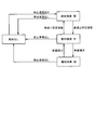
- FIG. 1 is a functional block diagram illustrating an embodiment.
- FIG. 2 is a flowchart
- FIG. 3 is a diagram showing transition of the notification mode
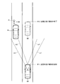
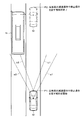
- FIG. 4 is a diagram (part 1) illustrating a relationship between the host vehicle and the stopped vehicle.
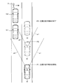
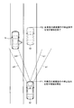
- FIG. 5 is a diagram (part 2) illustrating a relationship between the host vehicle and the stopped vehicle.
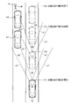
- FIG. 6 is a diagram (No. 3) showing the relationship between the host vehicle and the stopped vehicle.
- FIG. 7 is a diagram (part 4) illustrating the relationship between the host vehicle and the stopped vehicle.
- FIG. 8 is a diagram (part 5) illustrating a relationship between the host vehicle and the stopped vehicle.
- the driving support system 1 includes a driving support device 2, an in-vehicle camera 3 (corresponding to a photographing unit), a millimeter wave sensor 4 (corresponding to an object detection sensor), and a vehicle speed sensor 5 (corresponding to an own vehicle state detection sensor). ), Yaw rate sensor 6 (corresponding to own vehicle state detection sensor), steering angle sensor 7 (corresponding to own vehicle state detection sensor), navigation system 8, driver monitoring system 9, and notification device 10 And a brake ECU (Electronic Control Unit) 11.
- a driving support device 2 an in-vehicle camera 3 (corresponding to a photographing unit), a millimeter wave sensor 4 (corresponding to an object detection sensor), and a vehicle speed sensor 5 (corresponding to an own vehicle state detection sensor).
- Yaw rate sensor 6 corresponding to own vehicle state detection sensor
- steering angle sensor 7 corresponding to own vehicle state detection sensor
- navigation system 8 driver monitoring system 9
- notification device 10 And a brake ECU (Electronic Control Unit) 11.
- the in-vehicle camera 3 is disposed, for example, on the rear part of the rearview mirror or the front part of the vehicle body in the vehicle interior, and images the front of the vehicle and outputs a video signal including the captured image to the driving support device 2.
- the in-vehicle camera 3 is a CCD (Charge-Coupled Device) image sensor, a CMOS (Complementary-Metal-Oxide-Semiconductor) image sensor, or the like, and may be singular or plural.
- the millimeter wave sensor 4 is disposed, for example, in the front part of the vehicle body, transmits a millimeter wave (electromagnetic wave) to the front of the vehicle, detects an object in front of the vehicle according to the reception state of the reflected wave, and generates a detection signal including the detection result. Output to the driving support device 2.
- a configuration in which a radar (LADAR: Laser ⁇ ⁇ ⁇ ⁇ Detection and Ranging), a rider (LIDAR: Light Detection ⁇ ⁇ and Ranging), or the like may be adopted.
- the vehicle speed sensor 5 outputs a vehicle speed signal indicating the vehicle speed of the host vehicle to the driving support device 2.
- the yaw rate sensor 6 outputs a yaw rate signal indicating the yaw rate in the front-rear direction and the left-right direction of the host vehicle to the driving support device 2.
- the steering angle sensor 7 outputs a steering angle signal indicating the steering angle of the host vehicle to the driving support device 2.
- the navigation system 8 has a function of specifying the current position of the host vehicle, a function of specifying the type of road on which the host vehicle is traveling (for example, a general road, an automobile-only road, etc.) using map data, and the like.
- a navigation signal including various types of specified navigation information is output to the driving support device 2.
- the driver monitoring system 9 has a camera that photographs the upper body of the driver while the driver is sitting in the driver's seat.
- the driver monitoring system 9 uses the video captured by the camera to analyze the movement of the driver's head and eyeballs to detect the driver's gaze direction, and outputs a detection signal indicating the detection result to the driving support device 2.
- the camera employed in the driver monitoring system 9 is also a CCD image sensor, a CMOS image sensor, or the like, and may be singular or plural.
- the notification device 10 is a head-up display, a speaker, or the like.
- the notification device 10 starts displaying the notification information and outputting the sound and inputs the notification end command signal from the driving support device 2. Then, the display of the notification information and the sound output are ended.
- the brake ECU 11 drives the brake when a brake drive signal is input from the driving support device 2.
- the driving support device 2 includes a control unit 12.
- the control unit 12 includes a microcomputer having a CPU (Central Processing Unit), ROM (Read Only Memory), RAM (Random Access Memory), and I / O (Input / Output).
- the control unit 12 executes the computer program stored in the non-transitional tangible recording medium, thereby executing processing corresponding to the computer program and controlling the overall operation of the driving support device 2.
- the control unit 12 includes a passage determination unit 12a, a steering determination unit 12b, a road determination unit 12c, a notification control unit 12d, a deceleration control unit 12e, a vehicle type determination unit 12f, a door open determination unit 12g, A preceding vehicle determination unit 12h.
- Each of these units 12a to 12g is configured by a driving support program executed by the control unit 12, and is realized by software.
- the passage determination unit 12a determines whether or not the host vehicle will pass next to the stopped vehicle that is stopped in the adjacent lane adjacent to the traveling lane in which the host vehicle is traveling.
- the passage determination unit 12a includes a video signal input from the in-vehicle camera 3, a detection signal input from the millimeter wave sensor 4, a vehicle speed signal input from the vehicle speed sensor 5, a yaw rate signal input from the yaw rate sensor 6, and a steering angle.
- a steering angle signal input from the sensor 7 a navigation signal input from the navigation system 8, or the like, it is determined whether or not there is a stopped vehicle that is stopped in the traveling direction of the host vehicle in the adjacent lane.
- the passage determination unit 12a specifies, for example, that an object is present in the adjacent lane based on a detection signal input from the millimeter wave sensor 4, specifies the distance from the host vehicle to the object and the relative compatibility between the host vehicle and the object, and outputs the video signal.
- a characteristic point specific to the rear surface of the vehicle such as a tail lamp or a license plate is analyzed to identify a pattern similar to the rear surface of the vehicle, thereby identifying the object as a stopped vehicle.
- the passage determination unit 12a identifies the stopped vehicle in this way, and identifies the traveling state of the own vehicle based on the vehicle speed signal, the yaw rate signal, and the steering angle signal, so that the own vehicle is placed next to the stopped vehicle that is stopped in the adjacent lane. Is determined whether or not to pass.
- the steering determining unit 12b uses the steering angle signal input from the steering angle sensor 7 to determine whether or not the driver is steering due to, for example, a lane change or a left / right turn at an intersection.
- the road determination unit 12c uses the navigation signal input from the navigation system 8 to determine whether the road on which the host vehicle is traveling is an automobile-only road.
- the notification control unit 12d controls the output of the notification start command signal and the notification end command signal to the notification device 10, and starts and ends notification for prompting attention by the notification device 10 and for prompting a deceleration operation or stop operation of the host vehicle.
- the deceleration control unit 12e controls the output of the brake drive signal to the brake ECU 11, and controls the drive of the brake by the brake ECU 11.
- the vehicle type determination unit 12f determines the vehicle type of the stopped vehicle using, for example, a video signal input from the in-vehicle camera 3. For example, the vehicle type determination unit 12f identifies a stop vehicle as a normal vehicle by analyzing a characteristic point specific to the rear surface of a normal vehicle and identifies a pattern similar to a normal vehicle, and determines a characteristic point specific to the rear surface of a bus. By analyzing and identifying a pattern similar to a bus, the stop vehicle is identified as a bus.
- the door open determining unit 12g determines whether or not the door of the stopped vehicle is open using, for example, a video signal input from the in-vehicle camera 3 and a detection signal input from the millimeter wave sensor 4.
- the preceding vehicle determination unit 12h uses, for example, a video signal input from the in-vehicle camera 3 and a detection signal input from the millimeter wave sensor 4, and whether or not the preceding vehicle passing next to or passing through the stopped vehicle has decelerated or stopped. Determine whether.
- the preceding vehicle determination unit 12h receives a vehicle speed signal indicating the vehicle speed of the preceding vehicle through inter-vehicle communication, thereby determining whether or not the preceding vehicle passing next to or passing the stopped vehicle has decelerated or stopped. You may judge.
- the control unit 12 performs driving support processing.
- the control unit 12 starts the driving support process when a start condition of the driving support process is established, for example, the ignition switch is switched from OFF to ON.
- a start condition of the driving support process for example, the ignition switch is switched from OFF to ON.
- the control unit 12 may use, for example, a driving support process start condition such that the vehicle speed is equal to or higher than a certain speed or the driver performs a predetermined operation.
- the control unit 12 determines whether or not the own vehicle will pass next to the stopped vehicle stopped in the adjacent lane (S1, corresponding to the passage determination procedure).
- the control unit 12 determines whether or not the driver is steering due to, for example, a lane change or a right / left turn at an intersection (S2). ). If the control unit 12 determines that the driver is not steering, for example, due to a lane change or a right / left turn at an intersection (S2: NO), the control unit 12 determines whether the road on which the vehicle is traveling is an automobile-only road. (S3).
- control unit 12 determines that the road on which the host vehicle is traveling is not an automobile-only road (S3: NO)
- the control unit 12 outputs a notification start command signal to the notification device 10 and starts notification to call attention (S4: notification control).
- S4 notification control
- the control unit 12 displays, for example, a message such as “Please be careful about pedestrians jumping out” on the head-up display, or outputs sound from the speaker.
- the control unit 12 determines whether the notification mode change condition is satisfied (S5), and determines whether the notification end condition is satisfied (S6).
- the control unit 12 changes the notification mode (S7). For example, if the change of the vehicle speed is set as the notification mode change condition, the control unit 12 increases the notification intensity according to the vehicle speed becoming higher than the predetermined speed or increasing the vehicle speed, as shown in FIG. The notification intensity is weakened according to the fact that the speed has become less than the predetermined speed or has decreased. For example, when displaying a message on a head-up display, the control unit 12 changes the notification intensity by changing the content and color of the message. For example, when outputting a message from a speaker, the control unit 12 changes the notification intensity by changing the content, volume, and cycle of the message.
- the control unit 12 uses the change of the distance from the host vehicle to the stopped vehicle as a notification mode change condition, the control unit 12 can increase the notification intensity as the distance from the host vehicle to the stopped vehicle decreases (that is, approaches). good.
- the control unit 12 may increase the notification intensity according to the fact that the driver's line-of-sight direction deviates from the direction of the stopped vehicle.
- the control unit 12 reduces the notification intensity as the driver performs a deceleration operation, and the driver performs an acceleration operation. According to the above, the notification intensity may be increased.
- the control unit 11 determines whether or not the notification end condition is satisfied, the control unit 11 outputs a notification end command signal to the notification device 10 and ends the notification to call attention (S8).
- the control unit 12 uses the vehicle speed at that time and the distance from the own vehicle to the stopped vehicle to move the own vehicle next to the stopped vehicle.
- the timing to finish passing may be calculated, and the notification for calling attention may be ended using the calculated timing as the timing when the notification end condition is satisfied.
- the control unit 12 determines whether or not the end condition of the driving support process is satisfied (S9). If it determines with the completion
- the control unit 12 performs the above-described processing to set the shooting range (that is, the angle of view) of the in-vehicle camera 3 to a1 and a2, and the millimeter wave from the millimeter wave sensor 4.
- the transmission range is set to the range of b1 and b2
- the control part 12 continues the alerting
- the control unit 12 determines that the notification end condition is satisfied at the position P2 of the host vehicle M, the control unit 12 ends the notification for calling attention.
- control unit 12 determines whether or not there is a stopped vehicle by using not only the video signal input from the in-vehicle camera 3 but also the detection signal input from the millimeter wave sensor 4, so that the stopped vehicle is connected. Even when the vehicle is, the risk of pedestrians jumping out from the back side of the leading stop vehicle can be reduced. That is, as shown in FIG. 5, in the configuration in which the control unit 12 determines whether there is a stop vehicle in the adjacent lane only with the video signal input from the in-vehicle camera 3, The rear face of the last stop vehicle N1 is identified and the stop vehicle N1 is detected. When the host vehicle M is at the position P2, the rear face of the stop vehicle N2 that is stopped before the stop vehicle N1 is behind the stop vehicle N1.
- the control unit 12 determines that the notification end condition is satisfied at the position of the host vehicle M at P3, and ends the notification for calling attention.
- the control unit 12 determines whether there is a stopped vehicle using not only the video signal input from the in-vehicle camera 3 but also the detection signal input from the millimeter wave sensor 4.
- the rear surface of the last stop vehicle N1 is identified to detect the stop vehicle N1
- the rear surface of the stop vehicle N2 is stopped when the own vehicle M is at the position P2. Even if it is behind the vehicle N1, the rear surface of the stopped vehicle N2 cannot be identified, but the presence of the stopped vehicle N2 can be detected by receiving the reflected wave.
- the control unit 12 continues the alert for calling attention without determining that the notification end condition is satisfied when the own vehicle M is at the position P3, and the notification end condition is satisfied when the own vehicle M is at the position P4. Determination is made, and the notice for calling attention is terminated.
- the control unit 12 continues the alert for calling attention without determining that the notification end condition is satisfied when the own vehicle M is at the position P3, and the notification end condition is satisfied when the own vehicle M is at the position P4. Determination is made, and the notice for calling attention is terminated.
- the risk of the pedestrian X jumping out from the back side of the leading stopped vehicle can be reduced.
- 6 illustrates the case where two stopped vehicles N1 and N2 are connected, but the same applies to a case where three or more stopped vehicles are connected.
- the control unit 12 determines that the vehicle type of the stopped vehicle N is a bus using the video signal input from the in-vehicle camera 3 and the detection signal input from the millimeter wave sensor 4, Instead of the prompting notification, a notification for prompting a deceleration operation or a stop operation of the host vehicle may be performed. That is, when the stopped vehicle N is a bus, there is a risk that a person getting off the bus will jump out from the back side of the bus. Also good. In this case, the control unit 12 displays, for example, a message such as “Please perform a deceleration operation” or “Please perform a stop operation” on the head-up display or output a sound from the speaker.
- notification for prompting a deceleration operation or a stop operation of the host vehicle may be performed instead of the notification for prompting attention. That is, when the door of the stop vehicle N is open, there is a possibility that a person will get off from the stop vehicle N, and there is a risk that a person who gets off the stop vehicle N will jump out from the back side of the stop vehicle N. Instead of simply urging attention, a deceleration operation or a stop operation of the host vehicle may be urged. FIG.
- FIG. 8 illustrates the case where the right rear seat of the stopped vehicle N, that is, the door on the side of the traveling lane where the host vehicle is running is open, but the right front seat (that is, the right handle) of the stopped vehicle M is illustrated.
- the control unit 12 determines whether or not the preceding vehicle has decelerated or stopped. Instead of the notification, a deceleration operation or a stop operation of the host vehicle may be prompted. That is, when the control unit 12 determines that the preceding vehicle has decelerated or stopped, the control unit 12 determines that the driver of the preceding vehicle is likely to have noticed a pedestrian jumping from the back side of the stopped vehicle. It is also possible to prompt a deceleration operation or a stop operation.
- the control unit 12 may limit the target depending on whether the road on which the host vehicle is traveling is left-hand traffic or right-hand traffic. That is, if the host vehicle is facing traffic and traveling on a left-handed road, the control unit 12 performs notification on a stopped vehicle that is stopped in an adjacent lane adjacent to the left side of the traveling lane. The stop vehicle that is stopped in the adjacent lane adjacent to the right side with respect to the travel lane may be excluded from the notification.
- the control unit 12 notifies the target vehicle of a stopped vehicle that is stopped in an adjacent lane adjacent to the right side of the travel lane. It is not necessary to notify the stop vehicle that is stopped in the adjacent lane adjacent to the left side with respect to the travel lane.
- the following effects can be obtained.
- the driving support device 2 when it is determined that the own vehicle will pass the side of the stopped vehicle that is stopped in the adjacent lane adjacent to the traveling lane in which the own vehicle is traveling, a notification to call attention is made. Thereby, the danger with respect to the pedestrian jumping out from the back side of a stop vehicle can be reduced.
- the driving support device 2 even if it is determined that the own vehicle will pass next to the stopped vehicle, if the driver determines that the vehicle is steering, warning notification is not performed. As a result, for example, the situation where the host vehicle makes a right or left turn at the intersection can be excluded from the notification target, and the situation where the notification is unnecessarily performed can be avoided. it can.
- the driving support device 2 even if it is determined that the own vehicle will pass next to the stopped vehicle, if the road on which the own vehicle is traveling is determined to be an automobile-only road, the warning notification is not performed. . As a result, it is possible to exclude a situation in which the host vehicle is traveling on an automobile-only road where pedestrians are prohibited from entering, and avoid a situation in which notification is performed unnecessarily.
- the driving support device 2 it is determined whether or not there is a stopped vehicle by using not only a video signal input from the in-vehicle camera 3 but also a detection signal input from the millimeter wave sensor 4, and the vehicle speed sensor 5 inputs it.
- the vehicle speed signal, the yaw rate signal input from the yaw rate sensor 6, the steering angle signal input from the steering angle sensor 7, etc. are used to determine whether or not the host vehicle will pass next to the stopped vehicle. Thereby, even when stopped vehicles are connected, it is possible to reduce the risk of pedestrians jumping out from the back side of the leading stopped vehicle or from the gap between the stopped vehicles.
- the driving support device 2 determines that the vehicle type of the stopped vehicle is a bus
- a notification that prompts a deceleration operation or a stop operation of the host vehicle is performed instead of a notification that prompts attention.
- notification for prompting the deceleration operation or stop operation of the host vehicle is performed instead of the notification for prompting attention.
- more appropriate notification is performed by prompting a deceleration operation or a stop operation of the own vehicle instead of merely calling attention. be able to.
- the deceleration operation and the stop operation of the own vehicle are performed instead of the alerting notice. Notification to urge you to do.
- the target is limited depending on whether the road on which the vehicle is traveling is left-hand traffic or right-hand traffic. Thereby, it is possible to avoid a situation where an unnecessary notification is made in a situation where a pedestrian is unlikely to jump out.
- the brake When performing a warning to call attention, the brake may be driven to perform automatic deceleration control. In that case, for example, if the vehicle speed is less than a certain speed, only a notice for warning is given, and if the vehicle speed is equal to or higher than a certain speed, the notice for calling attention and automatic deceleration control may be performed together. Similarly, for example, if the distance from the own vehicle to the stopped vehicle is less than a certain distance, only an alert is issued, and if the distance from the own vehicle to the stopped vehicle is greater than a certain distance, an alert is issued and automatic deceleration control is performed. And may be performed together. Also, when notifying the vehicle to decelerate or stop the vehicle, the brake may be driven to perform automatic deceleration control.
Landscapes
- Engineering & Computer Science (AREA)
- Mechanical Engineering (AREA)
- Automation & Control Theory (AREA)
- Physics & Mathematics (AREA)
- General Physics & Mathematics (AREA)
- Transportation (AREA)
- Human Computer Interaction (AREA)
- Traffic Control Systems (AREA)
Abstract
運転支援装置(2)は、自車両が走行中の走行車線に対して隣接する隣接車線に停止中の停止車両の横を自車両がこれから通過するか否かを判定する通過判定部(12a)と、停止車両の横を自車両がこれから通過すると判定されると、注意を促す報知を行う報知制御部(12d)とを備える。
Description
本出願は、2016年5月19日に出願された日本出願番号2016-100465号に基づくもので、ここにその記載内容を援用する。
本開示は、運転支援装置及び運転支援プログラムに関する。
運転者が自車両から先行車両までの車間距離や自車両の車速を錯覚する可能性が高い状況であると判定すると、警告を行う運転支援装置が供されている。又、自車両が走行中の道路の勾配を算出し、所定角度以上の勾配で所定速度以上の車速であると判定すると、警告を行う運転支援装置も供されている(例えば特許文献1参照)。
車両が走行する状況の1つとして隣接車線に停止中の停止車両の横を通過する状況がある。その場合、停止車両の横をこれから通過する自車両の運転者にとって停止車両の奥側が死角となるので、停止車両の奥側からの歩行者の飛び出しに気付き難いという問題がある。
本開示は、隣接車線に停止中の停止車両の横を自車両がこれから通過する状況において、停止車両の奥側からの歩行者の飛び出しに対する危険を低減することができる運転支援装置及び運転支援プログラムを提供することにある。
本開示の一態様によれば、通過判定部は、自車両が走行中の走行車線に対して隣接する隣接車線に停止中の停止車両の横を自車両がこれから通過するか否かを判定する。報知制御部は、停止車両の横を自車両がこれから通過すると判定されると、注意を促す報知を行う。隣接車線に停止中の停止車両の横をこれから自車両が通過する状況になると、注意を促す報知を行うようにしたので、停止車両の奥側からの歩行者の飛び出しに対する危険を低減することができる。
本開示についての上記目的及びその他の目的、特徴や利点は、添付の図面を参照しながら下記の詳細な記述により、より明確になる。その図面は、
図1は、実施形態を示す機能ブロック図であり、
図2は、フローチャートであり、
図3は、報知態様の遷移を示す図であり、
図4は、自車両と停止車両との関係を示す図(その1)であり、
図5は、自車両と停止車両との関係を示す図(その2)であり、
図6は、自車両と停止車両との関係を示す図(その3)であり、
図7は、自車両と停止車両との関係を示す図(その4)であり、
図8は、自車両と停止車両との関係を示す図(その5)である。
以下、一実施形態について図面を参照して説明する。運転支援システム1は、運転支援装置2と、車載カメラ3(撮影部に相当する)と、ミリ波センサ4(物体検知センサに相当する)と、車速センサ5(自車両状態検知センサに相当する)と、ヨーレートセンサ6(自車両状態検知センサに相当する)と、操舵角センサ7(自車両状態検知センサに相当する)と、ナビゲーションシステム8と、運転者モニタリングシステム9と、報知デバイス10と、ブレーキECU(Electronic Control Unit)11とを有する。
車載カメラ3は、例えば車室内のルームミラーの背面部や車体前方部に配置されており、車両前方を撮影し、その撮影した映像を含む映像信号を運転支援装置2に出力する。車載カメラ3は、CCD(Charge Coupled Device)イメージセンサやCMOS(Complementary Metal Oxide Semiconductor)イメージセンサ等であり、単数であっても良いし複数であっても良い。
ミリ波センサ4は、例えば車体前方部に配置されており、車両前方にミリ波(電磁波)を送信し、反射波の受信状態により車両前方の物体を検知し、その検知結果を含む検知信号を運転支援装置2に出力する。尚、ミリ波センサ4を採用する代わりに、レーダー(LADAR:Laser Detection and Ranging)やライダー(LIDAR:Light Detection and Ranging)等を採用する構成でも良い。
車速センサ5は、自車両の車速を示す車速信号を運転支援装置2に出力する。ヨーレートセンサ6は、自車両の前後方向や左右方向のヨーレートを示すヨーレート信号を運転支援装置2に出力する。操舵角センサ7は、自車両の操舵角を示す操舵角信号を運転支援装置2に出力する。
ナビゲーションシステム8は、自車両の現在位置を特定する機能、自車両が走行中の道路の種別(例えば一般道路、自動車専用道路等)を地図データを用いて特定する機能等を有し、それらの特定した各種のナビゲーション情報を含むナビゲーション信号を運転支援装置2に出力する。
運転者モニタリングシステム9は、運転者が運転席に座った状態で運転者の上半身を撮影するカメラを有する。運転者モニタリングシステム9は、カメラが撮影した映像を用い、運転者の頭や眼球の動きを解析して運転者の視線方向を検知し、その検知結果を示す検知信号を運転支援装置2に出力する。運転者モニタリングシステム9に採用されるカメラも、CCDイメージセンサやCMOSイメージセンサ等であり、単数であっても良いし複数であっても良い。
報知デバイス10は、ヘッドアップディスプレイやスピーカーや等であり、運転支援装置2から報知開始指令信号を入力すると、報知情報の表示や音声出力を開始し、運転支援装置2から報知終了指令信号を入力すると、報知情報の表示や音声出力を終了する。ブレーキECU11は、運転支援装置2からブレーキ駆動信号を入力すると、ブレーキを駆動させる。
運転支援装置2は、制御部12を有する。制御部12は、CPU(Central Processing Unit)、ROM(Read Only Memory)、RAM(Random Access Memory)及びI/O(Input/Output)を有するマイクロコンピュータにより構成されている。制御部12は、非遷移的実体的記録媒体に格納されているコンピュータプログラムを実行することで、コンピュータプログラムに対応する処理を実行し、運転支援装置2の動作全般を制御する。
制御部12は、通過判定部12aと、操舵中判定部12bと、道路判定部12cと、報知制御部12dと、減速制御部12eと、車種判定部12fと、ドア開放中判定部12gと、先行車両判定部12hとを有する。これらの各部12a~12gは制御部12が実行する運転支援プログラムにより構成されており、ソフトウェアにより実現されている。
通過判定部12aは、自車両が走行中の走行車線に対して隣接する隣接車線に停止中の停止車両の横を自車両がこれから通過するか否かを判定する。具体的には、通過判定部12aは、車載カメラ3から入力する映像信号、ミリ波センサ4から入力する検知信号、車速センサ5から入力する車速信号、ヨーレートセンサ6から入力するヨーレート信号、操舵角センサ7から入力する操舵角信号、ナビゲーションシステム8から入力するナビゲーション信号等を用い、隣接車線に自車両の進行方向に停止中の停止車両が存在するか否かを判定する。通過判定部12aは、例えばミリ波センサ4から入力する検知信号により隣接車線に物体が存在すると特定し、自車両から物体までの距離及び自車両と物体との相対相度を特定し、映像信号により例えばテールランプやナンバープレート等の車両の後面に特有な特徴点を解析して車両の後面に類する模様を識別することで当該物体が停止車両であると特定する。通過判定部12aは、このようにして停止車両を特定し、車速信号、ヨーレート信号、操舵角信号により自車両の走行状態を特定することで、隣接車線に停止中の停止車両の横を自車両がこれから通過するか否かを判定する。
操舵中判定部12bは、操舵角センサ7から入力する操舵角信号を用い、運転者が例えば車線変更や交差点での右左折等により操舵中であるか否かを判定する。道路判定部12cは、ナビゲーションシステム8から入力するナビゲーション信号を用い、自車両が走行中の道路が自動車専用道路であるか否かを判定する。
報知制御部12dは、報知開始指令信号及び報知終了指令信号の報知デバイス10への出力を制御し、報知デバイス10による注意を促す報知や自車両の減速操作又は停止操作を促す報知の開始及び終了を制御する。減速制御部12eは、ブレーキ駆動信号のブレーキECU11への出力を制御し、ブレーキECU11によるブレーキの駆動を制御する。
車種判定部12fは、例えば車載カメラ3から入力する映像信号を用い、停止車両の車種を判定する。車種判定部12fは、例えば普通車の後面に特有な特徴点を解析して普通車に類する模様を識別することで停止車両が普通車であると特定し、バスの後面に特有な特徴点を解析してバスに類する模様を識別することで停止車両がバスであると特定する。
ドア開放中判定部12gは、例えば車載カメラ3から入力する映像信号及びミリ波センサ4から入力する検知信号を用い、停止車両のドアが開放中であるか否かを判定する。先行車両判定部12hは、例えば車載カメラ3から入力する映像信号及びミリ波センサ4から入力する検知信号を用い、停止車両の横をこれから通過する又は通過中の先行車両が減速又は停止したか否かを判定する。尚、先行車両判定部12hは、先行車の車速を示す車速信号を車車間通信により受信することで、停止車両の横をこれから通過する又は通過中の先行車両が減速又は停止したか否かを判定しても良い。
次に、上記した構成の作用について図2から図8を参照して説明する。
制御部12は運転支援処理を行う。制御部12は、例えばイグニッションスイッチがオフからオンに切り換わる等の運転支援処理の開始条件が成立すると、運転支援処理を開始する。尚、制御部12は、例えば車速が一定速度以上であること、運転者が所定操作を行ったこと等を運転支援処理の開始条件としても良い。
制御部12は運転支援処理を行う。制御部12は、例えばイグニッションスイッチがオフからオンに切り換わる等の運転支援処理の開始条件が成立すると、運転支援処理を開始する。尚、制御部12は、例えば車速が一定速度以上であること、運転者が所定操作を行ったこと等を運転支援処理の開始条件としても良い。
制御部12は、運転支援処理を開始すると、隣接車線に停止中の停止車両の横を自車両がこれから通過するか否かを判定する(S1、通過判定手順に相当する)。制御部12は、停止車両の横を自車両がこれから通過すると判定すると(S1:YES)、運転者が例えば車線変更や交差点での右左折等により操舵中であるか否かを判定する(S2)。制御部12は、運転者が例えば車線変更や交差点での右左折等により操舵中でないと判定すると(S2:NO)、自車両が走行中の道路が自動車専用道路であるか否かを判定する(S3)。制御部12は、自車両が走行中の道路が自動車専用道路でないと判定すると(S3:NO)、報知開始指令信号を報知デバイス10に出力し、注意を促す報知を開始する(S4:報知制御手順に相当する)。制御部12は、例えば「歩行者の飛び出しに注意してください」等のメッセージをヘッドアップディスプレイに表示したりスピーカーから音声出力したりする。
次いで、制御部12は、報知態様変更条件が成立したか否かを判定し(S5)、報知終了条件が成立したか否かを判定する(S6)。制御部12は、報知態様変更条件が成立したと判定すると(S6:YES)、報知態様を変更する(S7)。制御部12は、例えば車速が変化することを報知態様変更条件とすれば、図3に示すように、車速が所定速度以上になった又は車速が増大したことにしたがって報知強度を強め、車速が所定速度未満になった又は減少したことにしたがって報知強度を弱める。制御部12は、例えばメッセージをヘッドアップディスプレイに表示する場合であれば、メッセージの内容や色を変化させることで報知強度を変化させる。又、制御部12は、例えばメッセージをスピーカーから音声出力する場合であれば、メッセージの内容や音量や周期を変化させることで報知強度を変化させる。
報知態様変更条件としては、車速が変化することの他に、自車両から停止車両までの前後方向や左右方向の距離が変化すること、運転者の視線方向が変化すること、運転者が減速操作や加速操作を行うこと等を用いても良く、それらの幾つかを組み合わせても良い。制御部12は、自車両から停止車両までの距離が変化することを報知態様変更条件とすれば、自車両から停止車両までの距離が減少する(即ち近付く)ことにしたがって報知強度を強めても良い。又、制御部12は、運転者の視線方向が変化することを報知態様変更条件とすれば、運転者の視線方向が停止車両の方向から外れることにしたがって報知強度を強めても良い。又、制御部12は、運転者が減速操作や加速操作を行うことを報知態様変更条件とすれば、運転者が減速操作を行うことにしたがって報知強度を弱め、運転者が加速操作を行うことにしたがって報知強度を強めても良い。
制御部11は、報知終了条件が成立したか否かを判定すると、報知終了指令信号を報知デバイス10に出力し、注意を促す報知を終了する(S8)。制御部12は、例えば映像信号による車両の後面に類する模様の識別が不可になると、その時点での自車両の車速と自車両から停止車両までの距離を用いて自車両が停止車両の横を通過し終えるタイミングを算出し、その算出したタイミングを報知終了条件が成立するタイミングとして注意を促す報知を終了すれば良い。
制御部12は、運転支援処理の終了条件が成立したか否かを判定する(S9)。制御部12は、運転支援処理の終了条件が成立していないと判定すると(S9:NO)、ステップS1に戻り、ステップS1以降を繰返して行う。制御部12は、例えばイグニッションスイッチがオンからオフに切り換わる等の運転支援処理の終了条件が成立したと判定すると(S9:YES)、運転支援処理を終了する。尚、制御部12は、例えば車速が一定速度未満であること、運転者が所定操作を行ったこと等を運転支援処理の終了条件としても良い。
制御部12は、以上に説明した処理を行うことで、図4に示すように、車載カメラ3の撮影範囲(即ち画角)をa1,a2の範囲とし、ミリ波センサ4からのミリ波の送信範囲をb1,b2の範囲とした場合に、自車両MがP1の位置で停止車両Nの横を自車両がこれから通過すると判定すると、注意を促す報知を開始する。そして、制御部12は、自車両MがP2の位置に達するまで注意を促す報知を継続する。これにより、停止車両Nの奥側からの歩行者Xの飛び出しに対して運転者が注意することができ、停止車両Nの奥側からの歩行者Xの飛び出しに対する危険を低減することができる。制御部12は、自車両MがP2の位置で報知終了条件が成立したと判定すると、注意を促す報知を終了する。
又、制御部12は、車載カメラ3から入力する映像信号のみでなく、ミリ波センサ4から入力する検知信号も用いて停止車両が存在するか否かを判定することで、停止車両が連なっている場合でも先頭の停止車両の奥側からの歩行者の飛び出しに対する危険を低減することができる。即ち、制御部12は、図5に示すように、車載カメラ3から入力する映像信号のみで隣接車線に停止車両が存在するか否かを判定する構成では、自車両MがP1の位置では、最後尾の停止車両N1の後面を識別して停止車両N1を検知するが、自車両MがP2の位置では、停止車両N1の前に停止中の停止車両N2の後面が停止車両N1の陰となり、停止車両N2の後面を識別することができず停止車両N2の存在を検知することが困難となる。その結果、制御部12は、自車両MがP3の位置で報知終了条件が成立したと判定し、注意を促す報知を終了してしまう。
これに対し、制御部12は、図6に示すように、車載カメラ3から入力する映像信号のみでなく、ミリ波センサ4から入力する検知信号も用いて停止車両が存在するか否かを判定する構成では、自車両MがP1の位置では、最後尾の停止車両N1の後面を識別して停止車両N1を検知し、その後、自車両MがP2の位置では、停止車両N2の後面が停止車両N1の陰となっても、停止車両N2の後面を識別することができないが反射波を受信することで停止車両N2の存在を検知することが可能となる。その結果、制御部12は、自車両MがP3の位置では報知終了条件が成立したと判定せずに注意を促す報知を継続し、自車両MがP4の位置で報知終了条件が成立したと判定し、注意を促す報知を終了する。これにより、停止車両が連なっている場合でも先頭の停止車両の奥側からの歩行者Xの飛び出しに対する危険を低減することができる。勿論、停止車両同士の隙間からの歩行者Xの飛び出しに対する危険も低減することができる。尚、図6では2台の停止車両N1、N2が連なっている場合を例示したが、3台以上の停止車両が連なっている場合も同様である。
又、制御部12は、図7に示すように、車載カメラ3から入力する映像信号及びミリ波センサ4から入力する検知信号を用いて停止車両Nの車種がバスであると判定すると、注意を促す報知に代えて自車両の減速操作や停止操作を促す報知を行っても良い。即ち、停止車両Nがバスである場合には、バスから降りた人がバスの奥側から飛び出す危険性があるので、単に注意を促すのではなく、自車両の減速操作や停止操作を促しても良い。この場合、制御部12は、例えば「減速操作を行ってください」や「停止操作を行ってください」等のメッセージをヘッドアップディスプレイに表示したりスピーカーから音声出力したりする。
又、制御部12は、図8に示すように、車載カメラ3から入力する映像信号及びミリ波センサ4から入力する検知信号を用いて停止車両Nのドアが開放中であると判定すると、この場合も、注意を促す報知に代えて自車両の減速操作や停止操作を促す報知を行っても良い。即ち、停止車両Nのドアが開放中である場合には、停止車両Nから人が降りる可能性があり、その停止車両Nから降りた人が停止車両Nの奥側から飛び出す危険性があるので、単に注意を促すのではなく、自車両の減速操作や停止操作を促しても良い。尚、図8では、停止車両Nの右側後部席、即ち自車両が走行中の走行車線側のドアが開放中の場合を例示しているが、停止車両Mの右側前部席(即ち右ハンドル車であれば運転席)のドアが開放中の場合も同様であり、停止車両Nの左側席、即ち自車両が走行中の走行車線側とは反対側のドアが開放中の場合も同様である。
又、制御部12は、停止車両の横をこれから通過する又は通過中の先行車両が存在する場合には、その先行車両が減速又は停止したか否かを判定すると、この場合も、注意を促す報知に代えて自車両の減速操作や停止操作を促しても良い。即ち、制御部12は、先行車両が減速又は停止したと判定すると、先行車両の運転者が停止車両の奥側からの歩行者の飛び出しに気付いた可能性が高いと判定することで、自車両の減速操作や停止操作を促しても良い。
又、交差点で信号待ち中の車両を停止車両の対象として報知を行うと、歩行者が飛び出す可能性が低い状況でも不必要に報知を行うことになるので、このような事態を未然に回避すべく、制御部12は、自車両が走行中の道路が左側通行であるか右側通行であるかにより対象を限定しても良い。即ち、制御部12は、自車両が対面通行であって左側通行の道路を走行中であれば、走行車線に対して左側に隣接する隣接車線で停止中の停止車両については対象として報知を行い、走行車線に対して右側に隣接する隣接車線で停止中の停止車両については対象外として報知を行わなくても良い。同様に、制御部12は、自車両が対面通行であって右側通行の道路を走行中であれば、走行車線に対して右側に隣接する隣接車線で停止中の停止車両については対象として報知を行い、走行車線に対して左側に隣接する隣接車線で停止中の停止車両については対象外として報知を行わなくても良い。
以上説明したように本実施形態によれば、次に示す効果を得ることができる。
運転支援装置2において、自車両が走行中の走行車線に対して隣接する隣接車線に停止中の停止車両の横を自車両がこれから通過すると判定すると、注意を促す報知を行うようにした。これにより、停止車両の奥側からの歩行者の飛び出しに対する危険を低減することができる。
運転支援装置2において、自車両が走行中の走行車線に対して隣接する隣接車線に停止中の停止車両の横を自車両がこれから通過すると判定すると、注意を促す報知を行うようにした。これにより、停止車両の奥側からの歩行者の飛び出しに対する危険を低減することができる。
又、運転支援装置2において、停止車両の横を自車両がこれから通過すると判定しても運転者が操舵中であると判定すると、注意を促す報知を行わないようにした。これにより、例えば自車両が交差点で右左折したことで信号待ち中の停止車両の横を通過する状況を報知の対象から外すことができ、不必要に報知を行ってしまう状況を回避することができる。
又、運転支援装置2において、停止車両の横を自車両がこれから通過すると判定しても自車両が走行中の道路が自動車専用道路であると判定すると、注意を促す報知を行わないようにした。これにより、歩行者が進入禁止である自動車専用道路を自車両が走行中の状況を報知の対象から外すことができ、不必要に報知を行ってしまう状況を回避することができる。
又、運転支援装置2において、車載カメラ3から入力する映像信号のみでなく、ミリ波センサ4から入力する検知信号も用いて停止車両が存在するか否かを判定し、車速センサ5から入力する車速信号、ヨーレートセンサ6から入力するヨーレート信号、操舵角センサ7から入力する操舵角信号等を用いて停止車両の横を自車両がこれから通過するか否かを判定するようにした。これにより、停止車両が連なっている場合でも先頭の停止車両の奥側や停止車両同士の隙間からの歩行者の飛び出しに対する危険を低減することができる。
又、運転支援装置2において、停止車両の車種がバスであると判定すると、注意を促す報知に代えて自車両の減速操作や停止操作を促す報知を行うようにした。これにより、バスから降りた人がバスの奥側から飛び出す危険性がある場合に、単に注意を促すのではなく自車両の減速操作や停止操作を促すことで、より適切な報知を行うことができる。
又、運転支援装置2において、停止車両のドアが開放中であると判定すると、この場合も、注意を促す報知に代えて自車両の減速操作や停止操作を促す報知を行うようにした。これにより、停止車両から降りた人が停止車両の奥側から飛び出す危険性がある場合に、単に注意を促すのではなく自車両の減速操作や停止操作を促すことで、より適切な報知を行うことができる。
又、運転支援装置2において、停止車両の横をこれから通過する又は通過中の先行車両が減速又は停止したと判定すると、この場合も、注意を促す報知に代えて自車両の減速操作や停止操作を促す報知を行うようにした。これにより、先行車両の運転者が停止車両の奥側からの歩行者の飛び出しに気付いた可能性が高い場合に、単に注意を促すのではなく自車両の減速操作や停止操作を促すことで、より適切な報知を行うことができる。
又、運転支援装置2において、自車両が走行中の道路が左側通行であるか右側通行であるかにより対象を限定するようにした。これにより、歩行者が飛び出す可能性が低い状況で、不必要に報知を行ってしまう状況を回避することができる。
本開示は、実施形態に準拠して記述されたが、当該実施形態や構造に限定されるものではないと理解される。本開示は、様々な変形例や均等範囲内の変形をも包含する。加えて、様々な組み合わせや形態、更には、それらに一要素のみ、それ以上、或いはそれ以下、を含む他の組み合わせや形態をも、本開示の範疇や思想範囲に入るものである。
注意を促す報知を行う場合に、ブレーキを駆動して自動減速制御を併せて行っても良い。その場合、例えば車速が一定速度未満であれば注意を促す報知のみを行い、車速が一定速度以上であれば注意を促す報知と自動減速制御とを併せて行っても良い。同様に、例えば自車両から停止車両までの距離が一定距離未満であれば注意を促す報知のみを行い、自車両から停止車両までの距離が一定距離以上であれば注意を促す報知と自動減速制御とを併せて行っても良い。又、自車両の減速操作や停止操作を促す報知を行う場合にも、ブレーキを駆動して自動減速制御を併せて行っても良い。
Claims (14)
- 自車両が走行中の走行車線に対して隣接する隣接車線に停止中の停止車両の横を自車両がこれから通過するか否かを判定する通過判定部(12a)と、
停止車両の横を自車両がこれから通過すると判定されると、注意を促す報知を行う報知制御部(12d)と、を備えた運転支援装置(2)。 - 運転者が操舵中であるか否かを判定する操舵中判定部(12b)を備え、
前記報知制御部は、停止車両の横を自車両がこれから通過すると判定され且つ運転者が操舵中でないと判定されると、注意を促す報知を行い、停止車両の横を自車両がこれから通過すると判定されても運転者が操舵中であると判定されると、注意を促す報知を行わない請求項1に記載の運転支援装置。 - 自車両が走行中の道路が自動車専用道路であるか否かを判定する道路判定部(12c)を備え、
前記報知制御部は、停止車両の横を自車両がこれから通過すると判定され且つ自車両が走行中の道路が自動車専用道路でないと判定されると、注意を促す報知を行い、停止車両の横を自車両がこれから通過すると判定されても自車両が走行中の道路が自動車専用道路であると判定されると、注意を促す報知を行わない請求項1に記載の運転支援装置。 - 前記通過判定部は、自車両の進行方向を撮影する撮影部(3)により撮影された映像と、自車両の進行方向の物体を電磁波により検知する物体検知センサ(4)の検知結果と、自車両の状態を検知する自車両状態検知センサ(5~7)の検知結果とを用い、停止車両の横を自車両がこれから通過するか否かを判定する請求項1から3の何れか一項に記載の運転支援装置。
- 前記通過判定部は、前記撮影部により撮影された映像により停止車両が存在しないと判定されても、前記物体検知センサの検知結果と、前記自車両状態検知センサの検知結果とを用い、停止車両の横を自車両がこれから通過するか否かを判定する請求項4に記載の運転支援装置。
- 前記報知制御部は、自車両の車速と、自車両から停止車両までの前後方向や左右方向の距離と、運転者の視線方向と、運転者の運転操作の状態とのうち少なくとも何れかを用い、報知態様を変更する請求項1から5の何れか一項に記載の運転支援装置。
- 前記通過判定部は、停止車両の横を自車両がこれから通過するか否かに加え、停止車両の横を自車両が通過中であるか否かも判定し、
前記報知制御部は、停止車両の横を自車両がこれから通過すると判定されると、注意を促す報知を開始し、停止車両の横を自車両が通過中であると判定されると、注意を促す報知を継続する請求項1から6の何れか一項に記載の運転支援装置。 - 停止車両の横を自車両がこれから通過すると判定されると、自車両の自動減速制御を行う減速制御部(12e)を備えた請求項1から7の何れか一項に記載の運転支援装置。
- 停止車両の車種を判定する車種判定部(12f)を備え、
前記報知制御部は、停止車両の車種が特定の車種であると判定されると、自車両の減速操作又は停止操作を促す報知を行う請求項1から8の何れか一項に記載の運転支援装置。 - 停止車両のドアが開放中であるか否かを判定するドア開放中判定部(12g)を備え、
前記報知制御部は、停止車両のドアが開放中であると判定されると、自車両の減速操作又は停止操作を促す報知を行う請求項1から9の何れか一項に記載の運転支援装置。 - 停止車両の横をこれから通過する又は通過中の先行車両が減速又は停止したか否かを判定する先行車両判定部(12h)を備え、
前記報知制御部は、先行車両が減速又は停止したと判定されると、自車両の減速操作又は停止操作を促す報知を行う請求項1から10の何れか一項に記載の運転支援装置。 - 前記通過判定部は、自車両が対面通行であって左側通行の道路を走行中である場合には、走行車線に対して左側に隣接する隣接車線を対象として停止車両の横を自車両がこれから通過するか否かを判定し、自車両が対面通行であって右側通行の道路を走行中である場合には、走行車線に対して右側に隣接する隣接車線を対象として停止車両の横を自車両がこれから通過するか否かを判定する請求項1から11の何れか一項に記載の運転支援装置。
- 運転支援装置(2)の制御部(12)に、
自車両が走行中の走行車線に対して隣接する隣接車線に停止中の停止車両の横を自車両がこれから通過するか否かを判定する通過判定手順と、
停止車両の横を自車両がこれから通過すると判定すると、注意を促す報知を行う報知制御手順と、とを実行させる運転支援プログラム。 - 請求項13に記載の運転支援プログラムを記憶する、コンピュータ読み取り可能な非一時的な記憶媒体。
Priority Applications (1)
| Application Number | Priority Date | Filing Date | Title |
|---|---|---|---|
| US16/301,608 US10919449B2 (en) | 2016-05-19 | 2017-02-28 | Driving support device and storage medium |
Applications Claiming Priority (2)
| Application Number | Priority Date | Filing Date | Title |
|---|---|---|---|
| JP2016-100465 | 2016-05-19 | ||
| JP2016100465A JP6462629B2 (ja) | 2016-05-19 | 2016-05-19 | 運転支援装置及び運転支援プログラム |
Publications (1)
| Publication Number | Publication Date |
|---|---|
| WO2017199529A1 true WO2017199529A1 (ja) | 2017-11-23 |
Family
ID=60325939
Family Applications (1)
| Application Number | Title | Priority Date | Filing Date |
|---|---|---|---|
| PCT/JP2017/007806 Ceased WO2017199529A1 (ja) | 2016-05-19 | 2017-02-28 | 運転支援装置及び運転支援プログラム |
Country Status (3)
| Country | Link |
|---|---|
| US (1) | US10919449B2 (ja) |
| JP (1) | JP6462629B2 (ja) |
| WO (1) | WO2017199529A1 (ja) |
Cited By (1)
| Publication number | Priority date | Publication date | Assignee | Title |
|---|---|---|---|---|
| US12159463B2 (en) * | 2021-09-27 | 2024-12-03 | Toyota Jidosha Kabushiki Kaisha | Target vehicle recognition apparatus and processing method of target vehicle recognition apparatus |
Families Citing this family (18)
| Publication number | Priority date | Publication date | Assignee | Title |
|---|---|---|---|---|
| JP2019099012A (ja) * | 2017-12-05 | 2019-06-24 | 本田技研工業株式会社 | 車両制御システム、車両制御方法、およびプログラム |
| JP7379462B2 (ja) * | 2019-03-15 | 2023-11-14 | 本田技研工業株式会社 | 車両用コミュニケーション装置及びプログラム |
| JP7092702B2 (ja) * | 2019-03-19 | 2022-06-28 | 本田技研工業株式会社 | リスク推定装置及び自動運転装置 |
| JP6913716B2 (ja) * | 2019-07-17 | 2021-08-04 | 本田技研工業株式会社 | 車両制御装置、車両制御方法、及びプログラム |
| US11735051B2 (en) * | 2020-03-27 | 2023-08-22 | Toyota Research Institute, Inc. | Detection of bicyclists near ego vehicles |
| JP7477423B2 (ja) * | 2020-04-20 | 2024-05-01 | 本田技研工業株式会社 | 運転支援装置、運転支援方法、およびプログラム |
| JP7466396B2 (ja) * | 2020-07-28 | 2024-04-12 | 株式会社Soken | 車両制御装置 |
| CN114261331B (zh) * | 2020-09-16 | 2023-08-04 | 广州汽车集团股份有限公司 | 一种探测前方车辆开门的安全预警方法及系统 |
| JP7633807B2 (ja) * | 2020-12-28 | 2025-02-20 | 株式会社Subaru | 車両の運転制御システム |
| DE102021001519B4 (de) | 2021-03-23 | 2026-03-19 | Mercedes-Benz Group AG | Verfahren zur Kollisionsvermeidung bei sich öffnenden Fahrzeugtüren und Fahrzeug |
| US12162558B2 (en) * | 2021-12-28 | 2024-12-10 | Rad Power Bikes Inc. | Location-based lighting for an electric bicycle |
| JP7582237B2 (ja) * | 2022-03-17 | 2024-11-13 | トヨタ自動車株式会社 | 車両の運転支援システム |
| JP7469359B2 (ja) * | 2022-03-31 | 2024-04-16 | 本田技研工業株式会社 | 交通安全支援システム |
| JP7372382B2 (ja) | 2022-03-31 | 2023-10-31 | 本田技研工業株式会社 | 交通安全支援システム |
| JP7372381B2 (ja) | 2022-03-31 | 2023-10-31 | 本田技研工業株式会社 | 交通安全支援システム |
| JP7469358B2 (ja) | 2022-03-31 | 2024-04-16 | 本田技研工業株式会社 | 交通安全支援システム |
| JP7798746B2 (ja) | 2022-09-30 | 2026-01-14 | 本田技研工業株式会社 | 運転支援装置、運転支援方法、およびプログラム |
| CN116118776B (zh) * | 2023-01-03 | 2025-06-27 | 重庆长安汽车股份有限公司 | 车辆的安全控制方法、装置、电子设备及存储介质 |
Citations (3)
| Publication number | Priority date | Publication date | Assignee | Title |
|---|---|---|---|---|
| JP2008102690A (ja) * | 2006-10-18 | 2008-05-01 | Aisin Aw Co Ltd | 運転支援方法及び運転支援装置 |
| JP2014078056A (ja) * | 2012-10-09 | 2014-05-01 | Honda Elesys Co Ltd | 車両用領域識別装置、そのプログラム及びその方法 |
| JP2014160338A (ja) * | 2013-02-19 | 2014-09-04 | Isuzu Motors Ltd | 運転支援装置 |
Family Cites Families (10)
| Publication number | Priority date | Publication date | Assignee | Title |
|---|---|---|---|---|
| JP5187493B2 (ja) | 2006-11-27 | 2013-04-24 | ユー・ディー・シー アイルランド リミテッド | 有機電界発光素子および新規なインドール誘導体 |
| JP2008143387A (ja) * | 2006-12-11 | 2008-06-26 | Fujitsu Ten Ltd | 周辺監視装置および周辺監視方法 |
| JP2008158578A (ja) * | 2006-12-20 | 2008-07-10 | Tokai Rika Co Ltd | 車両の降車安全装置及び車両の安全降車方法 |
| JP2009043145A (ja) | 2007-08-10 | 2009-02-26 | Clarion Co Ltd | 速度監視装置、その制御方法及び制御プログラム |
| JP5098584B2 (ja) * | 2007-11-09 | 2012-12-12 | 日産自動車株式会社 | 車両用運転支援装置 |
| JP5174609B2 (ja) * | 2008-10-10 | 2013-04-03 | 日立オートモティブシステムズ株式会社 | 走行支援装置 |
| US8620549B2 (en) * | 2010-09-14 | 2013-12-31 | GM Global Technology Operations LLC | Vehicle safety systems and methods |
| CN104115201B (zh) * | 2012-02-23 | 2017-03-29 | 日产自动车株式会社 | 立体物检测装置 |
| US20130300551A1 (en) * | 2012-05-10 | 2013-11-14 | Steven J. Weber | Object proximity system |
| JP2014222421A (ja) * | 2013-05-14 | 2014-11-27 | 株式会社デンソー | 運転支援装置 |
-
2016
- 2016-05-19 JP JP2016100465A patent/JP6462629B2/ja not_active Expired - Fee Related
-
2017
- 2017-02-28 WO PCT/JP2017/007806 patent/WO2017199529A1/ja not_active Ceased
- 2017-02-28 US US16/301,608 patent/US10919449B2/en active Active
Patent Citations (3)
| Publication number | Priority date | Publication date | Assignee | Title |
|---|---|---|---|---|
| JP2008102690A (ja) * | 2006-10-18 | 2008-05-01 | Aisin Aw Co Ltd | 運転支援方法及び運転支援装置 |
| JP2014078056A (ja) * | 2012-10-09 | 2014-05-01 | Honda Elesys Co Ltd | 車両用領域識別装置、そのプログラム及びその方法 |
| JP2014160338A (ja) * | 2013-02-19 | 2014-09-04 | Isuzu Motors Ltd | 運転支援装置 |
Cited By (1)
| Publication number | Priority date | Publication date | Assignee | Title |
|---|---|---|---|---|
| US12159463B2 (en) * | 2021-09-27 | 2024-12-03 | Toyota Jidosha Kabushiki Kaisha | Target vehicle recognition apparatus and processing method of target vehicle recognition apparatus |
Also Published As
| Publication number | Publication date |
|---|---|
| US10919449B2 (en) | 2021-02-16 |
| JP2017207954A (ja) | 2017-11-24 |
| US20190283671A1 (en) | 2019-09-19 |
| JP6462629B2 (ja) | 2019-01-30 |
Similar Documents
| Publication | Publication Date | Title |
|---|---|---|
| JP6462629B2 (ja) | 運転支援装置及び運転支援プログラム | |
| US12597351B2 (en) | Vehicular automatic braking system | |
| CN108140314B (zh) | 停车辅助方法及停车辅助装置 | |
| JP7047763B2 (ja) | 運転支援装置および方法、移動体、並びにプログラム | |
| JP4517393B2 (ja) | 運転支援装置 | |
| WO2017145549A1 (ja) | 脇見見落とし注意システム及びコンピュータプログラム | |
| JP2018092505A (ja) | 運転支援装置 | |
| JP6344105B2 (ja) | 車両用警告システム | |
| JP2018081363A (ja) | 運転支援装置 | |
| JP7298744B2 (ja) | 運転支援装置 | |
| KR20230106207A (ko) | 적어도 하나 이상의 모드에 따라, 제어되는 차량 및 방법 | |
| US20250178629A1 (en) | Control device, driver assist method, and nontransitory computer storage medium | |
| US20240400113A1 (en) | Vehicle control device, vehicle control method and vehicle control computer program | |
| KR102175793B1 (ko) | 인지 장애 경고 방법 및 장치 | |
| JP2025003175A (ja) | 運転支援装置及び運転支援方法 | |
| JP2025003174A (ja) | 運転支援装置及び運転支援方法 | |
| CN121947350A (zh) | 车辆变道辅助方法、装置、车辆及存储介质 | |
| JP2023144579A (ja) | 衝突防止制御装置、衝突防止制御方法およびプログラム | |
| JP2024137321A (ja) | 脇見判定方法 | |
| CN116890861A (zh) | 驾驶辅助装置 | |
| WO2025062476A1 (ja) | 判定方法及び判定装置 | |
| CN121625789A (zh) | 车辆功能信息提供系统和车辆功能信息提供方法 | |
| CN117774990A (zh) | 报告控制装置、报告控制方法及存储介质 | |
| WO2017168954A1 (ja) | 車両周辺監視装置及びコンピュータプログラム |
Legal Events
| Date | Code | Title | Description |
|---|---|---|---|
| NENP | Non-entry into the national phase |
Ref country code: DE |
|
| 121 | Ep: the epo has been informed by wipo that ep was designated in this application |
Ref document number: 17798966 Country of ref document: EP Kind code of ref document: A1 |
|
| 122 | Ep: pct application non-entry in european phase |
Ref document number: 17798966 Country of ref document: EP Kind code of ref document: A1 |