WO2017199312A1 - ロータリソレノイド - Google Patents
ロータリソレノイド Download PDFInfo
- Publication number
- WO2017199312A1 WO2017199312A1 PCT/JP2016/064524 JP2016064524W WO2017199312A1 WO 2017199312 A1 WO2017199312 A1 WO 2017199312A1 JP 2016064524 W JP2016064524 W JP 2016064524W WO 2017199312 A1 WO2017199312 A1 WO 2017199312A1
- Authority
- WO
- WIPO (PCT)
- Prior art keywords
- casing
- rotary solenoid
- movable body
- magnet
- body portion
- Prior art date
Links
Images


Classifications
-
- H—ELECTRICITY
- H02—GENERATION; CONVERSION OR DISTRIBUTION OF ELECTRIC POWER
- H02K—DYNAMO-ELECTRIC MACHINES
- H02K33/00—Motors with reciprocating, oscillating or vibrating magnet, armature or coil system
- H02K33/16—Motors with reciprocating, oscillating or vibrating magnet, armature or coil system with polarised armatures moving in alternate directions by reversal or energisation of a single coil system
-
- H—ELECTRICITY
- H01—ELECTRIC ELEMENTS
- H01F—MAGNETS; INDUCTANCES; TRANSFORMERS; SELECTION OF MATERIALS FOR THEIR MAGNETIC PROPERTIES
- H01F7/00—Magnets
- H01F7/06—Electromagnets; Actuators including electromagnets
- H01F7/08—Electromagnets; Actuators including electromagnets with armatures
- H01F7/14—Pivoting armatures
-
- B—PERFORMING OPERATIONS; TRANSPORTING
- B65—CONVEYING; PACKING; STORING; HANDLING THIN OR FILAMENTARY MATERIAL
- B65H—HANDLING THIN OR FILAMENTARY MATERIAL, e.g. SHEETS, WEBS, CABLES
- B65H29/00—Delivering or advancing articles from machines; Advancing articles to or into piles
- B65H29/58—Article switches or diverters
-
- G—PHYSICS
- G07—CHECKING-DEVICES
- G07D—HANDLING OF COINS OR VALUABLE PAPERS, e.g. TESTING, SORTING BY DENOMINATIONS, COUNTING, DISPENSING, CHANGING OR DEPOSITING
- G07D11/00—Devices accepting coins; Devices accepting, dispensing, sorting or counting valuable papers
- G07D11/10—Mechanical details
- G07D11/16—Handling of valuable papers
- G07D11/18—Diverting into different paths or containers
-
- G—PHYSICS
- G07—CHECKING-DEVICES
- G07D—HANDLING OF COINS OR VALUABLE PAPERS, e.g. TESTING, SORTING BY DENOMINATIONS, COUNTING, DISPENSING, CHANGING OR DEPOSITING
- G07D11/00—Devices accepting coins; Devices accepting, dispensing, sorting or counting valuable papers
- G07D11/50—Sorting or counting valuable papers
-
- H—ELECTRICITY
- H01—ELECTRIC ELEMENTS
- H01F—MAGNETS; INDUCTANCES; TRANSFORMERS; SELECTION OF MATERIALS FOR THEIR MAGNETIC PROPERTIES
- H01F7/00—Magnets
- H01F7/06—Electromagnets; Actuators including electromagnets
- H01F7/08—Electromagnets; Actuators including electromagnets with armatures
- H01F7/081—Magnetic constructions
-
- H—ELECTRICITY
- H01—ELECTRIC ELEMENTS
- H01F—MAGNETS; INDUCTANCES; TRANSFORMERS; SELECTION OF MATERIALS FOR THEIR MAGNETIC PROPERTIES
- H01F7/00—Magnets
- H01F7/06—Electromagnets; Actuators including electromagnets
- H01F7/08—Electromagnets; Actuators including electromagnets with armatures
- H01F7/128—Encapsulating, encasing or sealing
-
- H—ELECTRICITY
- H02—GENERATION; CONVERSION OR DISTRIBUTION OF ELECTRIC POWER
- H02K—DYNAMO-ELECTRIC MACHINES
- H02K7/00—Arrangements for handling mechanical energy structurally associated with dynamo-electric machines, e.g. structural association with mechanical driving motors or auxiliary dynamo-electric machines
- H02K7/08—Structural association with bearings
- H02K7/083—Structural association with bearings radially supporting the rotary shaft at both ends of the rotor
-
- B—PERFORMING OPERATIONS; TRANSPORTING
- B65—CONVEYING; PACKING; STORING; HANDLING THIN OR FILAMENTARY MATERIAL
- B65H—HANDLING THIN OR FILAMENTARY MATERIAL, e.g. SHEETS, WEBS, CABLES
- B65H2301/00—Handling processes for sheets or webs
- B65H2301/30—Orientation, displacement, position of the handled material
- B65H2301/31—Features of transport path
- B65H2301/311—Features of transport path for transport path in plane of handled material, e.g. geometry
- B65H2301/3113—Features of transport path for transport path in plane of handled material, e.g. geometry vertical
-
- B—PERFORMING OPERATIONS; TRANSPORTING
- B65—CONVEYING; PACKING; STORING; HANDLING THIN OR FILAMENTARY MATERIAL
- B65H—HANDLING THIN OR FILAMENTARY MATERIAL, e.g. SHEETS, WEBS, CABLES
- B65H2301/00—Handling processes for sheets or webs
- B65H2301/30—Orientation, displacement, position of the handled material
- B65H2301/31—Features of transport path
- B65H2301/312—Features of transport path for transport path involving at least two planes of transport forming an angle between each other
- B65H2301/3124—Y-shaped
-
- B—PERFORMING OPERATIONS; TRANSPORTING
- B65—CONVEYING; PACKING; STORING; HANDLING THIN OR FILAMENTARY MATERIAL
- B65H—HANDLING THIN OR FILAMENTARY MATERIAL, e.g. SHEETS, WEBS, CABLES
- B65H2404/00—Parts for transporting or guiding the handled material
- B65H2404/60—Other elements in face contact with handled material
- B65H2404/63—Oscillating, pivoting around an axis parallel to face of material, e.g. diverting means
- B65H2404/632—Wedge member
-
- B—PERFORMING OPERATIONS; TRANSPORTING
- B65—CONVEYING; PACKING; STORING; HANDLING THIN OR FILAMENTARY MATERIAL
- B65H—HANDLING THIN OR FILAMENTARY MATERIAL, e.g. SHEETS, WEBS, CABLES
- B65H2701/00—Handled material; Storage means
- B65H2701/10—Handled articles or webs
- B65H2701/19—Specific article or web
- B65H2701/1912—Banknotes, bills and cheques or the like
-
- G—PHYSICS
- G07—CHECKING-DEVICES
- G07D—HANDLING OF COINS OR VALUABLE PAPERS, e.g. TESTING, SORTING BY DENOMINATIONS, COUNTING, DISPENSING, CHANGING OR DEPOSITING
- G07D2211/00—Paper-money handling devices
-
- H—ELECTRICITY
- H01—ELECTRIC ELEMENTS
- H01F—MAGNETS; INDUCTANCES; TRANSFORMERS; SELECTION OF MATERIALS FOR THEIR MAGNETIC PROPERTIES
- H01F7/00—Magnets
- H01F7/06—Electromagnets; Actuators including electromagnets
- H01F7/08—Electromagnets; Actuators including electromagnets with armatures
- H01F7/081—Magnetic constructions
- H01F2007/086—Structural details of the armature
-
- H—ELECTRICITY
- H01—ELECTRIC ELEMENTS
- H01F—MAGNETS; INDUCTANCES; TRANSFORMERS; SELECTION OF MATERIALS FOR THEIR MAGNETIC PROPERTIES
- H01F7/00—Magnets
- H01F7/06—Electromagnets; Actuators including electromagnets
- H01F7/08—Electromagnets; Actuators including electromagnets with armatures
- H01F7/121—Guiding or setting position of armatures, e.g. retaining armatures in their end position
- H01F7/122—Guiding or setting position of armatures, e.g. retaining armatures in their end position by permanent magnets
Definitions
- the present invention relates to a rotary solenoid including a fixed body portion having a casing provided with a bearing portion and a movable body portion having a rotation shaft that is rotatably supported by the bearing portion.
- a rotary solenoid having reciprocating rotation is used for various two-position switching applications such as a conveyance path switching for sorting banknotes and an optical path switching for optical equipment.
- a rotary solenoid used for such a switching application is not only reliable in operation but also often requires a contradictory performance between high-speed operation (high-speed processing) and downsizing (thinning).
- a rotary solenoid suitable for such a use a rotary solenoid disclosed in Patent Document 1 already proposed by the present applicant is known.
- the purpose of this rotary solenoid is to reduce the number of parts and reduce the number of assembly steps, and to reduce the overall size and size.
- the rotary solenoid uses a bearing portion provided on the casing.
- a magnetic field portion that can attract or repel the movable body portion.
- the shaft is arranged at a position corresponding to one corner portion of the triangle, and the S pole and N are located at positions corresponding to the remaining corner portions.
- a movable body part having a magnet part where each pole is generated, a field part having a single coil arranged with one end face in the coil axis direction facing the magnet part, and the movable body part is rotated. It is constructed by a movable body regulating portion for regulating the range of the predetermined range.
- the conventional rotary solenoid including a movable body part that pivots and displaces with a shaft as a fulcrum has the following problems to be solved.
- the coil is combined with an iron core (E-shaped yoke) to function as an electromagnet, and the coil axis is arranged in a positional relationship orthogonal to the axis of the shaft, resulting in a large component.
- the number of parts increases, such as the need for an iron core, and the overall structure based on the layout of the parts tends to be large. Therefore, there is a limit in realizing a reduction in size, particularly a reduction in thickness of the rotary solenoid, and it becomes a cause of weight increase and cost increase that cannot be ignored.
- the present invention aims to provide a rotary solenoid that solves such problems in the background art.
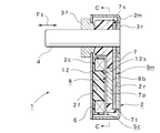
- the rotary solenoid 1 is rotated by a fixed body portion Sc having a casing 2 provided with a pair of bearing portions 3f and 3r positioned at the front and rear and a pair of bearing portions 3f and 3r.
- a rotary solenoid including a movable body portion Sm having a pivot shaft 4 that is freely supported.
- the stationary body portion Sc is orthogonal to the casing 2 made of a magnetic material and the axial direction Fs of the pivot shaft 4.
- the rotor yoke 7 having an air core coil 6 fixed to the inner surface 2f (or 2r) of the casing 2 serving as a surface, the movable body Sm being fixed to the rotating shaft 4 at one end 7s side, and the air core A pair of magnets 8a, 8 fixed to a facing surface 7p located on the other end 7t side of the rotor yoke 7 which is a surface facing the coil 6, and arranged along the rotation direction Fr of the facing surface 7p. Characterized in that by comprising a configuration and a magnet portion 8 having.
- the fixed body portion Sc and the movable body portion Sm also serve as a pair of restriction stopper mechanisms 11a and 11b that abut against each other and regulate the rotation angle range Zm of the movable body portion Sm.
- the fixed body portion Sc can be provided with a fixed block portion 12 made of a non-magnetic material that holds the air-core coil 6, and the movable body portion Sm is fixed to the rotating shaft 4 to be fixed to the rotor yoke 7.
- the movable block part 13 which consists of a nonmagnetic material holding the magnet part 8 can be provided.
- the movable block portion 13 can be provided with a pair of restricting surface portions 13a and 13b that constitute the restricting stopper mechanisms 11a and 11b in contact with the inner surfaces 2a and 2b of the casing 2.
- the fixed block portion 12 can be provided with a component holding portion 14 that holds one or more circuit components Pc connected to the air-core coil 6.
- the casing 2 can also serve as self-holding mechanisms 15a and 15b that suck the movable body Sm at the first position Xa and the second position Xb at both ends of the rotation angle range Zm and hold the position of the movable body Sm.
- the self-holding mechanisms 15 a and 15 b can be provided with suction piece portions 15 as and 15 bs formed by projecting a part of the casing 2.
- the shortest distance Ls in the axial direction Fs between the magnet 8a (8b) and the suction piece 15as (15bs) is preferably selected to be smaller than the thickness Lm of the magnet 8a (8b) in the axial direction Fs. Further, it is desirable that the magnet 8a (8b) and the attraction piece 15as (15bs) are arranged in a positional relationship that does not overlap each other in the axial direction Fs. Further, the shortest distance Ly... Between the end portion in the rotation direction Fr of the rotor yoke 7 at the first position Xa (second position Xb) and the inner surface 2a (2b) of the casing 2, and the first position Xa (second position Xb). The shortest distance Li ...
- the distance La between the rotor yoke 7 and the inner surface 2r (2f) of the casing 2 facing the rotor yoke 7 is preferably selected to be smaller than the thickness of the casing 2 on the inner surface 2r (2f).
- the rotary solenoid 1 according to the present invention having such a configuration has the following remarkable effects.
- the fixed body portion Sc is provided with the air core coil 6, the rotor yoke 7 having one end 7 s fixed to the rotating shaft 4 on the movable body portion Sm, and the rotor yoke 7 serving as a surface facing the air core coil 6. Since it includes a magnet portion 8 having a pair of magnets 8a and 8b fixed to the facing surface 7p located on the other end 7t side and disposed along the rotation direction Fr of the facing surface 7p, an iron core as a large component is provided. Since the number of parts can be reduced, such as being eliminated, and by arranging the axis of the air-core coil 6 and the axis of the rotary shaft 4 in parallel, the layout structure can be easily reduced in size (thinned). The entire solenoid 1 can be reduced in size, in particular, thinned easily, and the entire rotary solenoid 1 can be reduced in weight and cost.
- the inductance proportional to the magnetic permeability in the inner space of the air-core coil 6 can be made as small as several mH.
- the current can be raised to a saturation current almost instantaneously, so that extremely high responsiveness can be realized. Can contribute to the improvement of performance and processing speed.
- the fixed body portion Sc and the movable body portion Sm can be combined with a pair of restriction stopper mechanisms 11a and 11b that abut against each other and regulate the rotation angle range Zm of the movable body portion Sm.
- additional parts constituting the restriction stopper mechanisms 11a and 11b are not required, so that it is possible to reduce the number of parts, the number of assembly steps, and further downsizing and cost reduction.
- the air-core coil 6 can be accurately positioned by the fixed block portion 12. It can be easily assembled to the casing 2 while performing.
- a movable block portion 13 made of a nonmagnetic material that holds the rotor yoke 7 and the magnet portion 8 by fixing the movable body Sm to the rotating shaft 4 is provided on the movable body portion Sm according to a preferred embodiment, a synthetic resin material or the like Since the rotating shaft 4, the rotor yoke 7 and the magnet part 8 can be integrated on the basis of the movable block part 13 that can use the movable body part Sm, the movable body part Sm can be easily manufactured by an insert molding method or the like. The fixed strength (rigidity) between the moving shaft 4, the rotor yoke 7 and the magnet portion 8 can be improved and the positioning accuracy can be improved.
- the movable block 13 is provided with a pair of regulating surface portions 13a and 13b that constitute the regulating stopper mechanisms 11a and 11b in contact with the inner surfaces 2a and 2b of the casing 2 according to a preferred embodiment, a synthetic resin material or the like Since part of the movable block part 13 that can use this can be used as the restriction surface parts 13a and 13b, the restriction stopper mechanisms 11a and 11b can be easily constructed, and the rotation angle range Zm of the movable block part 13 can be easily set. be able to.
- the fixed block part 12 If the component holding part 14 holding one or more circuit parts Pc connected to the air core coil 6 is provided in the fixed block part 12 according to a preferred aspect, the fixed block adjacent to the air core coil 6 Since the circuit component Pc can be held (fixed) at a predetermined position of the portion 12, troubles such as disconnection on the energizing circuit including the lead wire led out from the air-core coil 6 can be avoided, and contribution to improvement in reliability can be achieved.
- the self-holding mechanisms 15a and 15b are constituted by suction pieces 15as and 15bs formed by projecting a part of the casing 2 according to a preferred embodiment, for example, when the casing 2 is manufactured, it is joined together by press molding or the like. Since it can be molded, it can be easily manufactured, and optimization related to the holding performance of the self-holding mechanisms 15a and 15b can be easily and flexibly performed.
- the shortest distance Ls in the axial direction Fs between the magnet 8a (8b) and the suction piece 15as (15bs) is selected to be smaller than the thickness Lm of the magnet 8a (8b) in the axial direction Fs. Then, under this selection condition, a sufficient self-holding function when the self-holding mechanisms 15a and 15b are configured can be ensured, and optimization thereof can be easily performed.
- the magnet 8a (8b) and the suction piece 15as (15bs) are arranged in a positional relationship that does not overlap with each other in the axial direction Fs according to a preferred embodiment, the magnet 8a (8b) Since the vector balance of the suction force of the suction piece 15as (15bs) can be optimized, a good self-holding function by the self-holding mechanisms 15a and 15b can be secured.
- the shortest distance Ly... Between the end portion in the rotation direction Fr of the rotor yoke 7 at the first position Xa (second position Xb) and the inner surface 2a (2b) of the casing 2 and the first position Xa.
- the shortest distance Li between the end of the magnet 8a (8b) in the rotation direction Fr at the (second position Xb) and the inner surface 2a (2b) of the casing 2 is the thickness Lm of the magnet 8a (8b) in the axial direction Fs. If it is selected to be smaller than the above, it can be implemented as an optimum form from the viewpoint of constructing the magnetic circuit of the rotary solenoid 1 according to the present invention, so that good magnetic properties can be ensured by the dimension under such selection conditions.
- the distance La between the rotor yoke 7 and the inner surface 2r (2f) of the casing 2 facing the rotor yoke 7 is selected to be smaller than the thickness of the casing 2 on the inner surface 2r (2f), Since the rotor yoke 7 and the casing 2 can be made to function as an integrated magnetic path, a good magnetic circuit that can suppress magnetic leakage and the like as much as possible can be constructed.
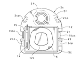
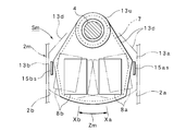
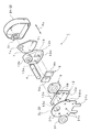
- FIG. 2 is a cross-sectional rear view of the rotary solenoid according to the preferred embodiment of the present invention taken along line CC in FIG. 2; Sectional side view of the rotary solenoid, The internal structure figure of the fixed body part which shows the inner surface of the cover side which constitutes the casing of the rotary solenoid, A partial cross-sectional front view showing an extracted movable body part of the rotary solenoid, An exploded perspective view of the rotary solenoid, Sectional plan view including a partially extracted enlarged view of the rotary solenoid, An electric circuit diagram showing an example of a drive device for the rotary solenoid; A signal waveform diagram of a control signal for driving and controlling the drive device; Installation outline diagram from the front direction showing the usage example of the rotary solenoid, Installation outline diagram from the side direction showing the usage example of the rotary solenoid, Magnetic field line distribution diagram when the rotary solenoid is stopped, Time vs.
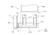
- the rotary solenoid 1 is roughly divided into a fixed body part Sc having a casing 2 provided with a pair of bearing parts 3f and 3r positioned at the front and rear, and a rotating shaft rotatably supported by the pair of bearing parts 3f and 3r. 4 and a movable body part Sm.
- the fixed body part Sc includes a casing 2 shown in FIGS. 1 and 2, and the casing 2 includes a housing part 2 m whose front surface is an open surface and a lid part 2 c that covers the open surface of the housing part 2 m.
- the inner surface of the lid portion 2 c is the front inner surface 2 f of the casing 2
- the inner surface of the housing portion 2 m facing (facing) the inner surface 2 f is the rear inner surface 2 r of the casing 2.
- the height dimension of the casing 2 illustrated in FIG. 1 is 16 [mm].
- the housing 2m is made of a soft magnetic (magnetic material) steel plate material such as a cold rolled steel plate and is formed in a box shape having an open surface on the front surface. At this time, if pure iron or silicon steel plate having a high saturation magnetic flux density is used, the plate thickness can be further reduced. On the other hand, if the thickness of the steel plate is selected to be about half of the thickness of the magnet 8a (8b) described later (0.5 to 2.0 [mm]), that is, relatively thick, the saturation of the magnetic circuit as the yoke is reduced. This can prevent magnetic flux leakage due to saturation. In addition, since vibration (amplitude) when the movable body portion Sm collides can be suppressed, there is an advantage that it can contribute to reduction of collision sound.
- a soft magnetic (magnetic material) steel plate material such as a cold rolled steel plate
- a bearing mounting hole is formed at an upper position in the inner surface 2r of the housing portion 2m, and a rear bearing portion 3r formed in a ring shape is mounted in the bearing mounting hole.
- a synthetic resin material can be used as the forming material, and the thickness in the axial direction Fs can be reduced.
- the lid 2c can also be formed of the same material as that of the housing 2m except that it is formed in a single plate shape. Further, a mounting circular hole is formed at an upper position in the inner surface 2f of the lid portion 2c, and the front bearing portion 3f having a ring shape is mounted in the mounting circular hole.
- the bearing portion 3f is integrally formed using a metal material, and the thickness in the axial direction Fs is also increased. And it fixes to the cover part 2c firmly by welding or caulking.
- the lid portion 2c when the lid portion 2c is assembled to the housing portion 2m, a plurality of (four examples) caulking piece portions 2mp are formed so as to protrude from the opening edge of the housing portion 2m (see FIG. 11). What is necessary is just to hold down the position of recessed part 2cp ... formed in 2c.
- the casing 2 can be easily assembled by the housing portion 2m and the lid portion 2c, and this casing 2 constitutes a part of a magnetic circuit (magnetic path) through which magnetic lines from magnets 8a and 8b described later pass. To do.
- the lid portion 2c functions as a substantially fixed body portion Sc. Therefore, a rectangular shape integrally formed of a synthetic resin material, which is an insulating material (nonmagnetic material), is provided at a lower position in the inner surface 2f of the lid portion 2c.
- the fixed block portion 12 is fixed.
- a plurality of pin-shaped convex portions 12p are formed on the mounting surface of the fixed block portion 12, and the convex portions 12p are inserted into the concave portions 2fc formed in the lid portion 2c.
- the fixed block portion 12 is positioned with respect to the lid portion 2c, and is fixed by thermally deforming the tip of the inserted convex portion 12p.
- the fixed block part 12 is not essential.
- a steel plate such as an electrogalvanized steel plate
- an insulating layer such as polyimide is provided on the surface of the steel plate, and an iron substrate having a copper foil pattern formed on the insulating layer is used, it will be described later.
- Electrical connection with the air-core coil 6 and lead wires, or mounting of a circuit component Pc such as a thermal fuse is possible on the inner surface 2f of the lid 2c, which can contribute to a reduction in assembly man-hours.
- a coil support convex portion 12 s that is inserted into the inner space of the air core coil 6 and positions and fixes the air core coil 6 is integrally formed and protruded.
- a component holding portion 14 that holds one or more circuit components Pc connected to the air core coil 6 is integrally formed at a portion where the air core coil 6 is not located.
- the component holding part 14 can be formed in a channel shape.
- the casing 2 is positioned while the air-core coil 6 is accurately positioned by the fixed block portion 12.
- the component holding portion 14 is formed integrally with the fixed block portion 12, the circuit component Pc can be held (fixed) at a predetermined position of the fixed block portion 12 adjacent to the air core coil 6. Troubles such as disconnection on the energization circuit including the lead wire to be derived can be avoided, and the reliability can be improved.
- the air core coil 6 is a single coil wound with a magnet wire (an annealed copper wire).
- the circular coil is configured to be slightly distorted into a rectangular shape (trapezoidal shape).
- the air-core coil 6 is exposed to hot air of several hundreds [° C.] and heat-sealed during winding in order to secure the adhesion strength between the magnet wires.
- the air-core coil 6 heat-sealed is press-molded in the thickness direction, the space factor of the conductor, that is, the ampere turn can be increased. Therefore, it is possible to contribute to the reduction in thickness of the entire rotary solenoid 1, and further, if a rectangular wire is used as the magnet wire, the ampere turn can be further increased.
- the air-core coil 6 is mounted on the fixed block portion 12 and fixed with an adhesive or the like, and the circuit component Pc is accommodated in the component holding portion 14 and fixed with an adhesive or the like.
- the illustrated circuit component Pc is a thermal fuse connected in series to the air-core coil 6.
- the circuit component Pc includes a lead wire (leader of the air-core coil 6) and the like.
- the movable body portion Sm includes a rotating shaft 4 that is rotatably supported by a pair of bearing portions 3f and 3r attached to the casing 2.
- the rotating shaft 4 is formed of a highly rigid metal material such as a stainless material. It does not matter whether the forming material is a magnetic material or a non-magnetic material. If a magnetic material is used, it can be used as a part of the magnetic circuit in the rotary solenoid 1.
- the movable block portion 13 integrally formed of a synthetic resin material that is an insulating material (non-magnetic material) is fixed on the rotating shaft 4.
- the movable block portion 13 may be a metal material having a small specific gravity such as aluminum or magnesium.
- PA resin material such as nylon material is used as the synthetic resin material, vibration absorption effect can be obtained, and if magnesium having the same weight as the synthetic resin material is used as the metal material, high strength is secured. A vibration absorbing effect can also be obtained.
- the movable block portion 13 includes a cylindrical block upper portion 13u positioned at the upper portion and a flat plate-shaped block lower portion 13d extending downward from the central position in the axial direction Fs of the block upper portion 13u. It fixes in the state which penetrated the intermediate position of the rotating shaft 4. FIG. In this case, it can be fixed by press-fitting or welding. In addition, it is desirable to further increase the fixing strength by forming a knurling or the like on the peripheral surface of the rotating shaft 4 that fixes the block upper portion 13u.
- a rotor yoke 7 having a similar shape slightly smaller than the movable block portion 13 is disposed on the rear surface of the movable block portion 13. Thereby, one end (upper end) 7 s side of the rotor yoke 7 is fixed to the rotating shaft 4.
- the rotor yoke 7 uses a soft magnetic (magnetic material) steel plate material such as a cold rolled steel plate, and the thickness Lp is about 2 mm, which is about half the thickness Lm in the axial direction Fs of the magnets 8a and 8b. It can be formed by a single plate selected.
- the thickness Lp of the rotor yoke 7 is considered to be a magnetic circuit combined with the adjacent casing 2, and the portion where the magnetic flux between the pair of magnets 8a and 8b is most concentrated can be used even if it is saturated. It is desirable to form. As a result, the efficiency of the magnetic circuit can be improved, and it can contribute to miniaturization and thinning.
- a magnet portion 8 comprising a pair of magnets 8a and 8b.
- the magnets 8a and 8b are formed in a flat rectangular parallelepiped shape whose thickness is selected as Lm..., And are arranged at predetermined intervals along the rotation direction Fr of the opposing surface 7p, that is, the turning direction. Arrange. As shown in FIG. 2, each magnet 8 a, 8 b penetrates the movable block portion 13 and is exposed on the front surface of the movable block portion 13.
- One magnet surface of each of the exposed magnets 8a and 8b is an N pole, and the other magnet surface is an S pole.
- the magnets 8a and 8b can be ferrite magnets, rare earth magnets, etc., and are not particularly limited. As an example, if an [Nd-Fe-B] magnet is used, a high air gap magnetic flux density can be obtained, so that the output torque can be increased, and if it is oriented (magnetized) in the thickness direction, the magnetic characteristics can be utilized to the maximum Thus, the magnetic flux density in the gap can be further increased. Further, if the thickness Lm of the magnets 8a and 8b is selected to be about 2 to 4 [mm] and the gap is selected to be about 4 to 8 [mm] which is almost doubled, a permeance coefficient of 0.5 or more can be obtained.
- the magnetic flux density of the air gap can be set to 0.5 [T] or more.
- a single magnet can be used for the pair of magnets 8a and 8b.
- the pair of magnets 8a and 8b includes a case where two-pole split magnetization is performed in the plane direction of the single magnet. It is.
- the movable body portion Sm includes the rotating shaft 4, the movable block portion 13, the rotor yoke 7, and the magnets 8a and 8b, the movable body portion Sm may be obtained by assembling them.
- the rotary shaft 4, the rotor yoke 7, and the magnets 8a and 8b may be insert-molded together. If such a movable block portion 13 is provided, the rotating shaft 4, the rotor yoke 7 and the magnet portion 8 can be integrated on the basis of the movable block portion 13 which can use a synthetic resin material or the like.
- the movable body portion Sm can be easily manufactured, and there is an advantage that the fixing strength (rigidity) between the rotating shaft 4, the rotor yoke 7 and the magnet portion 8 can be improved and the positioning accuracy can be improved.
- a pair of regulating stopper mechanisms 11a and 11b for regulating the rotation angle range Zm of the movable body Sm are provided inside the casing 2.
- the fixed body portion Sc and the movable body portion Sm described above are also used as a pair of restriction stopper mechanisms 11a and 11b.
- one side surface in the rotation direction Fr of the movable block portion 13 constituting the movable body portion Sm is formed as a restriction surface portion 13 a and the other side surface is formed as a restriction surface portion 13 b.
- the regulating surface portion 13a is in contact with the one inner surface 2a of the casing 2 so that the rotational displacement is regulated.
- the rotational displacement is restricted by the restriction surface portion 13b coming into contact with the other inner surface 2b of the casing 2. Therefore, one regulation surface part 13a on the movable body part Sm side and one inner surface 2a on the stationary body part Sc side constitute one regulation stopper mechanism 11a, and the other regulation surface part 13b on the movable body part Sm side and the stationary body.
- the other inner surface 2b on the side of the part Sc constitutes the other restriction stopper mechanism 11b.
- the restriction stopper Since the additional parts constituting the mechanisms 11a and 11b are not required, there is an advantage that the number of parts can be reduced, the number of assembling steps can be reduced, and the size and cost can be reduced.
- the movable block portion 13 is provided with a pair of regulating surface portions 13a and 13b that constitute the regulating stopper mechanisms 11a and 11b in contact with the inner surfaces 2a and 2b of the casing 2, the movable block portion that can use a synthetic resin material or the like.
- the restricting stopper mechanisms 11a and 11b can be easily constructed, and the rotation angle range Zm of the movable block portion 13 can be easily set.
- the movable body Sm at a position regulated by the regulation stopper mechanisms 11a and 11b is indicated by a virtual line.
- the rotation angle range Zm of the movable body portion Sm is a range regulated by the pair of regulation stopper mechanisms 11a and 11b, and the positions regulated by the pair of regulation stopper mechanisms 11a and 11b are both ends of the rotation angle range Zm.
- self-holding mechanisms 15a and 15b that suck the movable body part Sm at the first position Xa and the second position Xb to hold the position of the movable body part Sm are provided.
- the casing 2 is also used as the self-holding mechanisms 15a and 15b.
- a pair of cut portions 21 and 22 are formed on the end sides of the lid portion 2 c constituting the casing 2, and formed between the cut portions 21 and 22.
- One strip piece 15as is formed by bending a strip-shaped piece portion 90 [deg.] Inward.
- One self-holding mechanism 15a held at the first position Xa is configured.
- the other self-holding mechanism 15b is configured similarly to the one self-holding mechanism 15a except that the other self-holding mechanism 15b is symmetrical.
- Reference numeral 15bs denotes a suction piece in the other self-holding mechanism 15b.
- the movable body portion Sm includes the magnets 8a and 8b
- the suction piece portions 15as and 15bs formed on the casing 2 side constitute a pair of self-holding mechanisms 15a and 15b
- the casing 2 has a pair of self-holding mechanisms 15a. , 15b.
- the casing 2 is also used as a pair of self-holding mechanisms 15a and 15b, the additional parts constituting the self-holding mechanisms 15a and 15b are not necessary, so that the number of parts and the number of assembly steps can be reduced. Has the advantage of reducing the size and cost.
- the self-holding mechanisms 15a and 15b are constituted by suction piece portions 15as and 15bs formed by projecting a part of the casing 2, for example, when the casing 2 is manufactured, it can be molded together by press molding or the like. It can be manufactured, and optimization related to the holding performance of the self-holding mechanisms 15a and 15b can be easily and flexibly performed.
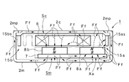
- the rotary solenoid 1 since the rotary solenoid 1 according to the present embodiment has a relatively simple configuration such as the use of an air-core coil 6, the dimension of details functions as an important element. In the following, particularly important elements related to the dimensions of each part will be described with reference to FIG.
- the shortest distance Ls in the axial direction Fs between the magnet 8a and the suction piece 15as is determined in the axial direction.
- the thickness is selected to be smaller than the thickness Lm of the magnet 8a at Fs, and the shortest distance Ls in the axial direction Fs between the magnet 8b and the attraction piece portion 15bs, specifically, the magnet 8b and attraction of the movable body portion Sm at the second position Xb.
- the shortest distance Ls between the pieces 15bs is selected to be smaller than the thickness Lm of the magnet 8b in the axial direction Fs. If such a condition is selected, there is an advantage that a sufficient self-holding function when the self-holding mechanisms 15a and 15b are configured can be secured and the optimization can be easily performed under the selected conditions.
- the magnet 8a and the suction piece 15as are arranged in a positional relationship that does not overlap each other in the axial direction Fs, and the magnet 8b and the suction piece 15bs are arranged in a positional relationship that does not overlap each other in the axial direction Fs.
- the gap Lg (Lg> 0) is selected between the magnet 8a and the suction piece 15as in the axial direction Fs, and the gap Lg is generated between the magnet 8b and the suction piece 15bs.
- the shortest distance Li between 2a is selected to be smaller than the thickness Lm of the magnet 8a in the axial direction Fs, and the shortest distance Ly between the end in the rotational direction Fr of the rotor yoke 7 and the inner surface 2b of the casing 2 at the second position Xb.
- the shortest distance Li between the end in the rotation direction Fr of the magnet 8b at the second position Xb and the inner surface 2b of the casing 2 is selected to be smaller than the thickness Lm of the magnet 8b in the axial direction Fs. If such a condition is selected, it can be implemented as an optimum form from the viewpoint of constructing the magnetic circuit of the rotary solenoid 1 according to the present invention, and therefore, there is an advantage that good magnetic characteristics can be secured by the dimension under the selected condition.
- the distance La between the rotor yoke 7 and the inner surface 2r of the casing 2 facing the rotor yoke 7 is selected to be smaller than the thickness Lc of the casing 2 on the inner surface 2r.
- FIG. 5 is an exploded perspective view of the rotary solenoid 1 according to the present embodiment. As is apparent from FIG. 5, each part can be assembled along the axial direction Fs.
- the assembly of the lid 2c is fitted (attached) by welding or caulking or the like by fitting the bearing portion 3f along the axial direction Fs from the outer surface side into the mounting circular hole formed at the upper position of the lid 2c.
- the fixed block portion 12 is assembled to the inner surface 2f of the lid 2c along the axial direction Fs, and a plurality of convex portions 12p are inserted into the concave portions 2fc, and then the tips of the convex portions 12p are thermally deformed. To fix.
- the inner space of the air-core coil 6 is incorporated from the axial direction Fs into the coil support convex portion 12 s of the fixed block portion 12, and the circuit component Pc is incorporated into the component holding portion 14 from the axial direction Fs. Thereby, the assembly of the cover body 2c can be obtained.
- the assembly of the movable body portion Sm may be integrally formed by an insert molding method, or may be manufactured by a normal assembly method.
- the rotor yoke 7 is assembled from the axial direction Fs to the back surface of the movable block portion 13 to be a resin molded product, and thereafter, the magnets 8a and 8b are respectively attached from the surface side of the movable block portion 13. Assembly is performed along the axial direction Fs. Further, the rotation shaft 4 is inserted and fixed to the movable block portion 13 from the axial direction Fs. Thereby, the assembly of movable body part Sm can be obtained.
- the bearing 3r is mounted along the axial direction Fs from the inner surface side into the mounting circular hole formed at the upper position of the housing 2m. Thereafter, the rotation shaft 4 of the movable body portion Sm is inserted into the bearing portion 3r from the rear end side from the axial direction Fs, and the front end side of the rotation shaft 4 is fixed to the lid portion 2c. Then, it is inserted along the axial direction Fs from the inner surface side. Then, if the four crimping piece portions 2mp... Projectingly formed on the housing portion 2m are bent (caulking) and the recesses 2cp of the lid portion 2c are pressed and fixed, the rotary according to the present embodiment shown in FIGS. The solenoid 1 can be obtained.
- each part can be assembled along the axial direction Fs, so that the manufacturing process can be completely automated and the manufacturing can be performed very easily. This can contribute to cost reduction.
- the fixed body portion Sc includes the air core coil 6 and the movable body portion Sm has the one end 7 s fixed to the rotating shaft 4 and the rotor yoke 7. And a pair of magnets 8a and 8b fixed to the facing surface 7p located on the other end 7t side of the rotor yoke 7 which is a surface facing the air-core coil 6, and arranged along the rotation direction Fr of the facing surface 7p. Since it is constructed with a basic configuration including the magnet section 8, it is possible to reduce the number of parts, such as eliminating the iron core that is a large part, and the axis of the air-core coil 6 and the axis of the rotary shaft 4 are arranged in parallel.
- the layout structure can be easily reduced in size (thinned), so that the entire rotary solenoid 1 can be easily reduced in size, in particular, reduced in thickness, and the rotary solenoid can be easily realized.
- Id 1 can contribute to the overall weight and cost.
- the inductance proportional to the magnetic permeability in the inner space of the air-core coil 6 can be made as small as several mH.
- the current can be raised to a saturation current almost instantaneously, so that extremely high responsiveness can be realized. Can contribute to the improvement of performance and processing speed.
- FIG. 7 shows an example of a drive device 30 suitable for use in the rotary solenoid 1 according to the present embodiment
- FIG. 8 shows an example of a drive pulse Ps suitable for use in the drive device 30.
- reference numeral 6 denotes the air-core coil of the rotary solenoid 1 described above, and in this case, circuit components (thermal fuse etc.) Pc are also included. Further, since two lead wires from the air-core coil 6 lead out to the rotary solenoid 1, each lead wire is connected to the driving device 30.
- the driving device 30 includes a driving circuit 31 connected to two lead wires, a DC power source 32 for supplying DC power (DC / 24 [V]) to the driving circuit 31, and a first switching pulse Pa to the driving circuit 31. And a switching pulse generator 33 that applies the second switching pulse Pb, and an adjustment unit 34 that is connected to the switching pulse generator 33 and adjusts the OFF time (end time) of the first switching pulse Pa and the second switching pulse Pb. Prepare.
- the drive circuit 31 includes two PNP transistors Q1, Q2, four NPN transistors Q3, Q4, Q5, Q6, four diodes D1, D2, D3, D4, and eight resistance elements R1, R2, R3. R4... R8 are provided, and an electric circuit is configured by the connections shown in FIG. Thereby, when the rotary solenoid 1 is driven, the first switching pulse Pa shown in FIG. 8A is applied to the base of the NPN transistor Q3, and the second switching pulse Pb shown in FIG. 8B is applied to the NPN transistor Q5. Granted to the base. As a result, the drive pulse Ps shown in FIG. 8C is applied to both ends of the air-core coil 6. This drive pulse Ps is a waveform that matches the pulse waveform obtained by adding the first switching pulse Pa and the second switching pulse Pb in which the positive and negative polarities are inverted, except for the magnitude.
- the forward current Ii [A] flows through the air-core coil 6.
- the air-core coil 6 is excited in the positive direction, and an energizing torque Tfd due to Lorentz force is generated according to Fleming's left-hand rule. Therefore, the movable body portion Sm is located between the magnet 8b and the suction piece portion 15bs at the second position Xa.
- the holding torque Tfc is overcome and rotation to the first position Xa side is started. Thereafter, the energization torque Tfd increases and reaches the maximum torque at the center position.
- the first position Xa is reached at a substantially maximum speed. That is, the first position Xa is switched. Note that, at the first position Xa, the magnetic flux density decreases due to the influence of the magnetic circuit, and thus the magnitude of the energization torque Tfd also decreases.
- the magnetic lines of force Ff from the N pole of the magnet 8a reach the S pole of the other magnet 8b through the space in the casing 2 and the lid portion 2c.
- the lid 2c includes a suction piece 15as formed integrally with the lid 2c. Further, the magnetic lines of force Ff through the lid 2c pass through the housing 2m, pass through the gap between the housing 2m and the rotor yoke 7, and then reach the S pole of the magnet 8a through the rotor yoke 7. On the other hand, the magnetic field lines Ff...
- the tip portion and the attracting piece 15as in the rotation direction Fr of the magnet 8a are closer to each other by the shortest distance Ls (see FIG. 6), and the magnetic material The suction piece portion 15as and the magnet 8a formed by the above are sucked.
- the restriction by the restriction stopper mechanism 11a that is, the restriction surface portion 13a of the movable block portion 13 in the movable body portion Sm is brought into contact with the inner surface 2a of the casing 2 to restrict the position.
- the movable body portion Sm is held at the first position Xa by the restriction stopper mechanism 11a and the self-holding mechanism 15a.
- the movable body Sm is displaced to the second position Xb, it is held at the second position Xb by the same action.
- the rotary solenoid 1 according to the present embodiment can be used as a two-position switching device shown in FIGS. 9 and 10 as an example of usage.
- FIG. 9 and 10 show an outline of the banknote sorting apparatus 50 that distributes the banknote Mo transported on the transport path 51 to the first passage 52 or the second passage 53.
- FIG. In the banknote sorting apparatus 50, the rotary solenoid 1 according to the present embodiment is installed at three branch portions of the transport path 51, the first approach path 52, and the second approach path 53, and the rotary solenoid 1 is rotated.
- a flapper unit 41 is attached to the moving shaft 4.
- the flapper unit 41 is preferably formed as lightly as possible using a plastic material or the like. Further, the flapper unit 41 includes a base portion 41m coaxially attached to the tip of the rotating shaft 4, and a pair of flapper portions 41f and 41f that are provided apart from each other in the axial direction of the base portion 41m.
- the flapper portions 41f and 41f in FIG. 9 are switched to the position (first position Xa) indicated by the solid line rotated and rotated counterclockwise, the transport path 51 and the first entry path 52 are connected. Therefore, the banknote Mo conveyed by the conveyance path 51 can be caused to enter the first entry path 52 in the arrow Fc direction. Further, if the flapper portions 41f and 41f are switched to a position (second position Xb) indicated by an imaginary line that is rotationally displaced clockwise, the conveyance path 51 and the second entry path 53 are connected. The banknote Mo conveyed 51 can be caused to enter the second approach path 53 in the arrow Fce direction.
- the rotary solenoid 1 when the rotary solenoid 1 is used for switching the flapper unit 41 of the banknote sorting apparatus 50 as described above, the rotary solenoid 1 has a reliable and reliable switching based on a certain output torque. Is required. In addition to this, since it is necessary to arrange in a limited installation space, it is necessary to reduce the size and size as much as possible and to increase the processing quantity as much as possible, so high-speed processing (high-speed switching operation) is also required. . In addition, since electric power is used, basically, reduction of power consumption and further improvement of energy saving and economy are also required.
- the rotary solenoid 1 according to the present embodiment can meet such a request by an approach from a mechanical structure, and can also meet such a request by an approach from a control method described below.
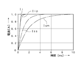
- FIG. 12 shows the time [ms] when the positive pulse Pp of the drive pulse Ps shown in FIG. 8C is applied to the air-core coil 6 by the first switching pulse Pa shown in FIG.
- the change characteristic of the positive direction current Ii [A] is shown. Since the rotary solenoid 1 according to the present embodiment uses the air-core coil 6 to form the fixed body portion Sc, as described above, the inductance of the air-core coil 6 is the magnetic permeability of the inner space of the air-core coil 6. Can be set to a slight size of about several mH.
- a characteristic curve of current when an iron plate is stacked on the back surface of the air-core coil 6 is indicated by Iip. Further, a characteristic curve of current when an iron core is inserted into about half of the air core portion of the air core coil 6 is indicated by Iss. Furthermore, Ism represents a current characteristic curve when an iron core that fills the inner space is inserted inside the air-core coil 6. As is apparent from FIG. 12, the characteristic curve Iip can obtain the same characteristics as the characteristic curve Ii from the viewpoint of satisfying the high-speed response.
- the air-core coil 6 is a concept including not only the case where no magnetic material is added to the air-core coil 6 but also the case where an iron plate is used on the back surface of the air-core coil 6.
- the inductance of the air core coil 6 is It is almost equal to or less than the case where iron plates are stacked on the back. That is, the current characteristic curve in this case is substantially the same as Iip, and can be regarded as the air-core coil 6 when this condition is satisfied.
- the control method based on the present embodiment that is, the energization time Tp indicated by the solid line in FIG. 8 was used.
- This energization time Tp is applied with the positive pulse Pp, and the rotation position of the movable body portion Sm at the second position Xb is an intermediate position, specifically, the rotation angle from the second position Xb to the first position Xa.
- the positive pulse Pp is applied at a midway position (midway timing) when the movable body Sm is turned 10 to 50 [%] of the rotation angle range Zm from the second position Xb. It is to turn off.
- the energization time Tr indicated by the phantom line in FIG. 8C is a known general energization time, and energization is performed in the entire rotation angle range Zm from the second position Xb to the first position Xa. Shows the case. Therefore, in this case, after applying the positive pulse Pp and the movable body part Sm at the second position Xb reaches the first position Xa due to rotational displacement, the application of the positive pulse Pp is released at a stable timing. In other words, it is a control method based on full energization control.
- the control method based on this embodiment is a control method based on the initial energization control, which is controlled based on the elapsed time until midway.
- FIG. 13 is a change characteristic diagram of the rotation angle [°] of the movable body portion Sm with respect to time [ms] including a comparative example when the rotary solenoid 1 according to the present embodiment is driven by the driving device 30, and
- FIG. 15 is an explanatory diagram of the principle of the change characteristic of the rotation angle [°] of the movable body portion Sm with respect to time [ms], and FIG. 15 shows the output torque [with respect to the rotation angle [°] when the movable body portion Sm is rotationally displaced.
- the change characteristic diagram of N ⁇ m] is shown respectively.
- the movable body portion Sm is a magnet at the second position Xb.
- the second position is accelerated by a torque exceeding the holding torque Tfc based on the suction action of 8b and the suction piece 15bs, and takes approximately 8 [ms] as shown by the change characteristic Xr indicated by the phantom line in FIG. While reaching the first position Xa from Xb, the bouncing is repeated twice, and is self-held after approximately 12 [ms].
- the range in which the movable body portion Sm is rotationally displaced is the rotational angle range Zm, which is 20 [°].
- the excitation is released after approximately 20 [ms], and thereafter, the non-excitation is performed over a period of approximately 80 [ms]. Maintain power.
- the first switching pulse used for this all energization control becomes a virtual line Par shown in FIG.
- the rotational displacement of the movable body portion Sm is an acceleration displacement by a quadratic function as shown by the change characteristic Xr shown in FIG.
- a large bounce occurs. Therefore, control is performed to turn off the positive pulse Pp after a certain period of time after the hold state. Note that when reaching the first position Xa, bounce is suppressed as much as possible by voltage suppression control, brake pulse control, or the like, but some bounce is unavoidable.
- the positive pulse Pp is turned off at the midway position (set position) Px from the second position Xb to the first position Xa as shown by the change characteristic Xi indicated by the solid line in FIG. To do.
- the rotation angle at the illustrated midway position Px is approximately 4.3 [°], and is approximately 22% of the rotation angle range Zm.
- This midway position Px is approximately 4 [ms] in time and corresponds to the energization time Tp.
- the movable body portion Sm continues to be rotationally displaced as it is by the inertial force (moment of inertia), and if it approaches the first position Xa, The magnet 8a and the attraction piece 15as are displaced to the first position Xa by the attraction action.
- the rotational displacement of the movable body portion Sm is a linear displacement, that is, a constant velocity motion from the midway position Px as shown by the change characteristic Xi shown in FIG. Therefore, even if a slight bounce occurs at the first position Xa, the number and size of the bounces are reduced, and the first position Xa is held at about 13 [ms] as shown in FIG.
- the energization time Tp is desirably secured at least four times the response time constant of the current Ii (illustration is 0.5 [ms]). As a result, a current equal to or greater than 98% of the saturation current can be secured, so that acceleration close to the maximum torque can be achieved.
- the time required for the rotational displacement of the movable body portion Sm is almost the same as that in the case of performing the normal full energization control, but the energization time Tp is approximately 1. / 5 and power consumption can be reduced to 1/5.
- the current response time constant is 0.5 [ms]. Therefore, if the power consumption becomes 1/5, the temperature rise of the air-core coil 6 also becomes 1/5. Therefore, when the temperature rise of the air-core coil 6 at the time of full energization control when the energization time Tr is 20 [ms] (duty ratio 20%) is 100 [° C.], the energization time Tp is 4 [ms] (duty ratio 4). %) During the initial energization control, the temperature rise of the air-core coil 6 is suppressed to about 20 [° C.].
- the increase in resistance value will remain at about 8 [%], so there is no possibility of causing troubles such as burning, and a reduction in output torque. Can be neglected, and the configuration can be simplified.
- the decrease in the output torque when the temperature rise of the air-core coil 6 is 100 [° C.] driven by a constant voltage circuit, the output torque is inversely proportional to the resistance value, so the resistance value increases by 40 [%]. In addition, the output torque is about 70%.
- the rotation angle from the second position Xb is 10 to 50% of the rotation angle range Zm.
- the timing reached is desirable. 13 to 15, the selectable release range Ze, that is, a range of 10 to 50 [%] is indicated by hatching.
- Pd shown in FIG. 14 indicates a release position at a relatively early stage, and this release position Pd is approximately 5% of the rotation angle range Zm.
- the positive side pulse Pp is turned OFF at the release position Pd
- the movable body portion Sm thereafter is rotationally displaced along the change characteristic Kd that is a tangent to the change characteristic Xr at the release position Pd.
- the arrival time td at the first position Xa where the change characteristic Kd is extended is approximately 18 [ms].
- the arrival time te (12 [ms]) at the time of all energization control shown in FIG. 13 since a considerably long time elapses from the arrival time te (12 [ms]) at the time of all energization control shown in FIG. 13, it is impossible to respond to a request for speeding up due to a decrease in responsiveness. Moreover, it is turned off before the actual energization torque Tfd is generated.
- Pu indicates a release position at a relatively late stage, and this release position Pu is approximately 50% of the rotation angle range Zm.
- the positive pulse Pp is turned OFF at the release position Pu, it is almost the same as that during full energization control (change characteristic Xr).
- the movable body Sm thereafter is rotationally displaced along the change characteristic Ku that is a tangent to the change characteristic Xr at the release position Pu. Therefore, the arrival time tu at the first position Xa where the change characteristic Ku is extended is approximately 8 [ms].
- the first position Xa is more unstable because it is a collision in a state where no energization is performed.
- Pm indicates a release position located between the release positions Pd and Pu, and Km indicates a change characteristic that is a tangent at the release position Pm.
- the holding torque Tfc generated by the attraction between the magnet 8a and the attraction piece 15as at the first position Xa can be arbitrarily set according to the application, etc., but when using the control method according to the embodiment, the air core It is desirable to set to 10 to 50% of the energization torque Tfd generated when the coil 6 is energized. In order to set the energization torque Tfd at the first position Xa to 50 to 80 [%] of the central position where the maximum torque (the energization torque Tfd) is generated, it is necessary to start it securely. It is desirable to make it 50% or less with respect to the maximum energization torque Tfd at the center position.
- FIG. 15 shows change characteristics when the holding torque Tfc is set to 10 [%] and 50 [%].
- FIG. 15 shows a change in output torque (energization torque + holding torque) when the holding torque Tfc is set to 50% of the energizing torque Tfd and turned OFF within the setting range Ze of 10 to 50%. Characteristic Ti is shown.
- FIG. 15 shows, as a comparative example, a change characteristic when a general drive pulse corresponding to the characteristic curve Xr of FIG. 13 is applied over the entire section and there is no holding torque based on the holding piece 15as.
- Tr and the holding torque are set to 10% of the torque generated when the air-core coil 6 is energized
- the holding torque change characteristic Ths and the holding torque are 50% of the torque generated when the air-core coil 6 is energized.
- the holding torque change characteristic Thm, the change characteristic Tr and the characteristic Trs obtained by adding the change characteristic Ths, and the change characteristic Tr and the characteristic Trm obtained by adding the change characteristic Thm are respectively shown.
- the operation based on the positive side pulse Pp has been mainly described, but the basic case is also applicable when the negative side pulse Pn shown in FIG. 8C is applied to switch the movable body portion Sm at the first position Xa to the second position Xb.
- the typical operation is the same as in the case of the positive pulse Pp.
- the air core coil 6 is fixed to the inner surface 2f of the lid portion 2c which is the front, and the movable body portion Sm having the magnets 8a and 8b is arranged behind this. is there. Therefore, the movable body portion Sm is sucked forward, and stress due to suction acts on the front bearing portion 3f. For this reason, it is necessary to increase the mechanical strength of the bearing portion 3f, and on the other hand, the mechanical strength of the rear bearing portion 3r can be kept low.
- the air-core coil 6 is fixed to the inner surface 2r of the rear casing 2m, and the movable body Sm having magnets 8a and 8b is arranged in front of this. is there. Therefore, in this case, the movable body portion Sm is attracted rearward, and stress due to the suction acts on the rear bearing portion 3r. For this reason, it is necessary to increase the mechanical strength of the rear bearing portion 3r.
- the rear bearing portion 3r is also assembled with the same one as the front bearing portion 3f. The front bearing portion 3f is not subjected to internal stress, but is subjected to an external load as a working end.
- the present invention is not limited to such an embodiment, and the detailed configuration, shape, material, quantity, technique, and the like do not depart from the gist of the present invention. It can be changed, added, or deleted arbitrarily.
- the case where the fixed body portion Sc and the movable body portion Sm are combined with a pair of regulating stopper mechanisms 11a and 11b that abut against each other and regulate the rotation angle range Zm of the movable body portion Sm is shown.
- the case where the restriction stopper portions 11a and 11b are separately provided is not excluded, and the case where the restriction stopper portions 11a and 11b are provided on the rotating shaft 4 protruding outside the casing 2 is not excluded.
- the movable block part 13 made of a non-magnetic material for holding the rotor yoke 7 and the magnet part 8 by fixing the movable body part Sm to the rotating shaft 4
- the movable block part 13 is It does not exclude the case where it is not used.
- maintains the one or two or more circuit components Pc connected to the air-core coil 6 was provided in the fixed block part 12 was illustrated, it is arbitrary whether to provide.
- the casing 2 is also used as the self-holding mechanisms 15a and 15b for holding the position of the movable body portion Sm by the suction action with respect to the movable body portion Sm at both end positions Xa and Xb of the rotation angle range Zm is shown.
- this does not exclude the case where a separate part is attached.
- stop controls such as voltage suppression control and brake pulse control.
- the rotary solenoid according to the present invention is a two-position switching actuator in various devices having various switching functions such as a sorting function for money, banknotes, etc., a sorting function for postal items, a transport path switching function for printed matter, an optical path switching function, etc. Available as
Landscapes
- Physics & Mathematics (AREA)
- Electromagnetism (AREA)
- Engineering & Computer Science (AREA)
- Power Engineering (AREA)
- General Physics & Mathematics (AREA)
- Mechanical Engineering (AREA)
- Electromagnets (AREA)
- Reciprocating, Oscillating Or Vibrating Motors (AREA)
Abstract
Description
Claims (12)
- 前後に位置する一対の軸受部を設けたケーシングを有する固定体部及び前記一対の軸受部により回動自在に支持される回動シャフトを有する可動体部を備えるロータリソレノイドであって、前記固定体部を、磁性材よりなるケーシングと、前記回動シャフトの軸方向に対して直交する面となる前記ケーシングの内面に固定した空芯コイルとを備えて構成するとともに、前記可動体部を、一端側を前記回動シャフトに固定したロータヨークと、前記空芯コイルに対向する面となる前記ロータヨークの他端側に位置する対向面に固定し、かつ当該対向面の回動方向に沿って配した一対のマグネットを有するマグネット部とを備えて構成してなることを特徴とするロータリソレノイド。
- 前記固定体部と前記可動体部は、相互に当接することにより当該可動体部の回動角範囲を規制する一対の規制ストッパ機構を兼用することを特徴とする請求項1記載のロータリソレノイド。
- 前記固定体部は、前記空芯コイルを保持する非磁性材よりなる固定ブロック部を備えることを特徴とする請求項1又は2記載のロータリソレノイド。
- 前記固定ブロック部は、前記空芯コイルに接続する一又は二以上の回路部品を保持する部品保持部を有することを特徴とする請求項3記載のロータリソレノイド。
- 前記可動体部は、前記回動シャフトに固定することにより前記ロータヨーク及び前記マグネット部を保持する非磁性材よりなる可動ブロック部を備えることを特徴とする請求項1又は2記載のロータリソレノイド。
- 前記可動ブロック部は、前記ケーシングの内面に当接して前記規制ストッパ機構を構成する一対の規制面部を有することを特徴とする請求項5記載のロータリソレノイド。
- 前記ケーシングは、前記回動角範囲の両端の第一位置と第二位置における前記可動体部を吸引して当該可動体部の位置を保持する自己保持機構を兼用することを特徴とする請求項2記載のロータリソレノイド。
- 前記自己保持機構は、前記ケーシングの一部を突出形成した吸引片部を備えることを特徴とする請求項7記載のロータリソレノイド。
- 前記マグネットと前記吸引片部間の前記軸方向における最短距離は、前記軸方向における前記マグネットの厚みよりも小さく選定することを特徴とする請求項8記載のロータリソレノイド。
- 前記マグネットと前記吸引片部は、前記軸方向において相互にオーバーラップしない位置関係に配することを特徴とする請求項8又は9記載のロータリソレノイド。
- 前記第一位置と前記第二位置における前記ロータヨークの前記回動方向の端部と前記ケーシングの内面間の最短距離,及び前記第一位置と前記第二位置における前記マグネットの前記回動方向の端部と前記ケーシングの内面間の最短距離は、前記軸方向における前記マグネットの厚みよりも小さく選定することを特徴とする請求項7記載のロータリソレノイド。
- 前記ロータヨークとこのロータヨークに対面する前記ケーシングの内面間の距離は、この内面における当該ケーシングの厚みよりも小さく選定することを特徴とする請求項1記載のロータリソレノイド。
Priority Applications (5)
| Application Number | Priority Date | Filing Date | Title |
|---|---|---|---|
| US16/302,497 US11114231B2 (en) | 2016-05-16 | 2016-05-16 | Rotary solenoid |
| JP2018517954A JP6764932B2 (ja) | 2016-05-16 | 2016-05-16 | ロータリソレノイド |
| PCT/JP2016/064524 WO2017199312A1 (ja) | 2016-05-16 | 2016-05-16 | ロータリソレノイド |
| CN201680085721.4A CN109155579B (zh) | 2016-05-16 | 2016-05-16 | 旋转螺线管 |
| KR1020187033542A KR20190005889A (ko) | 2016-05-16 | 2016-05-16 | 로터리 솔레노이드 |
Applications Claiming Priority (1)
| Application Number | Priority Date | Filing Date | Title |
|---|---|---|---|
| PCT/JP2016/064524 WO2017199312A1 (ja) | 2016-05-16 | 2016-05-16 | ロータリソレノイド |
Publications (1)
| Publication Number | Publication Date |
|---|---|
| WO2017199312A1 true WO2017199312A1 (ja) | 2017-11-23 |
Family
ID=60324963
Family Applications (1)
| Application Number | Title | Priority Date | Filing Date |
|---|---|---|---|
| PCT/JP2016/064524 WO2017199312A1 (ja) | 2016-05-16 | 2016-05-16 | ロータリソレノイド |
Country Status (5)
| Country | Link |
|---|---|
| US (1) | US11114231B2 (ja) |
| JP (1) | JP6764932B2 (ja) |
| KR (1) | KR20190005889A (ja) |
| CN (1) | CN109155579B (ja) |
| WO (1) | WO2017199312A1 (ja) |
Cited By (1)
| Publication number | Priority date | Publication date | Assignee | Title |
|---|---|---|---|---|
| CN111354597A (zh) * | 2018-12-20 | 2020-06-30 | Abb瑞士股份有限公司 | 用于中压断路器的致动器 |
Citations (3)
| Publication number | Priority date | Publication date | Assignee | Title |
|---|---|---|---|---|
| JP2009038874A (ja) * | 2007-07-31 | 2009-02-19 | Oki Micro Giken Kk | ロータリーアクチュエータ |
| JP2012039721A (ja) * | 2010-08-05 | 2012-02-23 | Tokyo Parts Ind Co Ltd | ロータリアクチュエータ |
| JP2014132803A (ja) * | 2012-10-16 | 2014-07-17 | Oki Micro Giken Kk | 揺動型アクチュエータ |
Family Cites Families (9)
| Publication number | Priority date | Publication date | Assignee | Title |
|---|---|---|---|---|
| US3680083A (en) * | 1971-01-25 | 1972-07-25 | Miniature Elect Components | Three position electromagnetic indicator |
| JPS5434013A (en) * | 1977-08-20 | 1979-03-13 | Shinano Tokki Kk | Electromagnetic rotating apparatus |
| JPH0681478B2 (ja) * | 1987-01-19 | 1994-10-12 | 沖電気工業株式会社 | ロータリアクチュエータ |
| US5952760A (en) * | 1996-09-30 | 1999-09-14 | Seiko Epson Corporation | Brushless DC motor |
| JP5405894B2 (ja) * | 2008-05-13 | 2014-02-05 | 沖マイクロ技研株式会社 | 往復回転アクチュエータ |
| WO2012111658A1 (ja) * | 2011-02-17 | 2012-08-23 | 日本電産サーボ株式会社 | ロータリーソレノイド |
| JP5815372B2 (ja) * | 2011-11-09 | 2015-11-17 | 沖マイクロ技研株式会社 | ロータリーアクチュエータ |
| JP2013103142A (ja) * | 2011-11-10 | 2013-05-30 | Minebea Co Ltd | 振動装置 |
| JP5613731B2 (ja) | 2012-07-24 | 2014-10-29 | タカノ株式会社 | ロータリソレノイド |
-
2016
- 2016-05-16 WO PCT/JP2016/064524 patent/WO2017199312A1/ja active Application Filing
- 2016-05-16 US US16/302,497 patent/US11114231B2/en active Active
- 2016-05-16 KR KR1020187033542A patent/KR20190005889A/ko unknown
- 2016-05-16 JP JP2018517954A patent/JP6764932B2/ja active Active
- 2016-05-16 CN CN201680085721.4A patent/CN109155579B/zh active Active
Patent Citations (3)
| Publication number | Priority date | Publication date | Assignee | Title |
|---|---|---|---|---|
| JP2009038874A (ja) * | 2007-07-31 | 2009-02-19 | Oki Micro Giken Kk | ロータリーアクチュエータ |
| JP2012039721A (ja) * | 2010-08-05 | 2012-02-23 | Tokyo Parts Ind Co Ltd | ロータリアクチュエータ |
| JP2014132803A (ja) * | 2012-10-16 | 2014-07-17 | Oki Micro Giken Kk | 揺動型アクチュエータ |
Cited By (2)
| Publication number | Priority date | Publication date | Assignee | Title |
|---|---|---|---|---|
| CN111354597A (zh) * | 2018-12-20 | 2020-06-30 | Abb瑞士股份有限公司 | 用于中压断路器的致动器 |
| CN111354597B (zh) * | 2018-12-20 | 2022-03-15 | Abb瑞士股份有限公司 | 用于中压断路器的致动器 |
Also Published As
| Publication number | Publication date |
|---|---|
| KR20190005889A (ko) | 2019-01-16 |
| JPWO2017199312A1 (ja) | 2019-03-14 |
| US11114231B2 (en) | 2021-09-07 |
| JP6764932B2 (ja) | 2020-10-07 |
| US20190279803A1 (en) | 2019-09-12 |
| CN109155579B (zh) | 2021-10-01 |
| CN109155579A (zh) | 2019-01-04 |
Similar Documents
| Publication | Publication Date | Title |
|---|---|---|
| US9473007B2 (en) | Oscillating rotary swing actuator with rotary solenoid and projecting fixed yoke | |
| JPH08251901A (ja) | 電磁駆動装置 | |
| JP2015079672A (ja) | 電磁継電器 | |
| JP2009038874A (ja) | ロータリーアクチュエータ | |
| JP2013030309A (ja) | 電磁リレー | |
| WO2017199312A1 (ja) | ロータリソレノイド | |
| WO2017199313A1 (ja) | ロータリソレノイドの駆動制御方法 | |
| WO2019150658A1 (ja) | 電磁継電器 | |
| CN111052288B (zh) | 断路器 | |
| JP2012175735A (ja) | ロータリーソレノイド | |
| JP6933060B2 (ja) | 電磁継電器 | |
| JP2754296B2 (ja) | ロータリアクチュエータ | |
| JPH064565Y2 (ja) | 電磁手段 | |
| JP2002335662A (ja) | 三安定自己保持電磁石 | |
| JPH082906Y2 (ja) | 電磁継電器 | |
| JP2013153098A (ja) | ロータリーソレノイド | |
| JP3836554B2 (ja) | 光量調節装置 | |
| JP5995078B2 (ja) | 電磁リレー | |
| WO2023119957A1 (ja) | 電磁継電器 | |
| JPH10127033A (ja) | 可動磁石型リニアアクチュエータ | |
| KR100206996B1 (ko) | 전자 접촉기 | |
| JPH10225084A (ja) | ボイスコイル形リニアモータ | |
| JP2007221049A (ja) | 電磁アクチュエータ | |
| JP2019095508A (ja) | アクチュエータ、羽根駆動装置、撮像装置及び電子機器 | |
| JPH02125406A (ja) | 単安定電磁石 |
Legal Events
| Date | Code | Title | Description |
|---|---|---|---|
| WWE | Wipo information: entry into national phase |
Ref document number: 2018517954 Country of ref document: JP |
|
| NENP | Non-entry into the national phase |
Ref country code: DE |
|
| ENP | Entry into the national phase |
Ref document number: 20187033542 Country of ref document: KR Kind code of ref document: A |
|
| 121 | Ep: the epo has been informed by wipo that ep was designated in this application |
Ref document number: 16902332 Country of ref document: EP Kind code of ref document: A1 |
|
| 122 | Ep: pct application non-entry in european phase |
Ref document number: 16902332 Country of ref document: EP Kind code of ref document: A1 |