WO2017195627A1 - エンジン制御装置 - Google Patents
エンジン制御装置 Download PDFInfo
- Publication number
- WO2017195627A1 WO2017195627A1 PCT/JP2017/016759 JP2017016759W WO2017195627A1 WO 2017195627 A1 WO2017195627 A1 WO 2017195627A1 JP 2017016759 W JP2017016759 W JP 2017016759W WO 2017195627 A1 WO2017195627 A1 WO 2017195627A1
- Authority
- WO
- WIPO (PCT)
- Prior art keywords
- engine
- rotation
- speed
- descent
- rotation speed
- Prior art date
- Legal status (The legal status is an assumption and is not a legal conclusion. Google has not performed a legal analysis and makes no representation as to the accuracy of the status listed.)
- Ceased
Links
Images


Classifications
-
- B—PERFORMING OPERATIONS; TRANSPORTING
- B60—VEHICLES IN GENERAL
- B60W—CONJOINT CONTROL OF VEHICLE SUB-UNITS OF DIFFERENT TYPE OR DIFFERENT FUNCTION; CONTROL SYSTEMS SPECIALLY ADAPTED FOR HYBRID VEHICLES; ROAD VEHICLE DRIVE CONTROL SYSTEMS FOR PURPOSES NOT RELATED TO THE CONTROL OF A PARTICULAR SUB-UNIT
- B60W20/00—Control systems specially adapted for hybrid vehicles
- B60W20/10—Controlling the power contribution of each of the prime movers to meet required power demand
- B60W20/15—Control strategies specially adapted for achieving a particular effect
- B60W20/17—Control strategies specially adapted for achieving a particular effect for noise reduction
-
- B—PERFORMING OPERATIONS; TRANSPORTING
- B60—VEHICLES IN GENERAL
- B60K—ARRANGEMENT OR MOUNTING OF PROPULSION UNITS OR OF TRANSMISSIONS IN VEHICLES; ARRANGEMENT OR MOUNTING OF PLURAL DIVERSE PRIME-MOVERS IN VEHICLES; AUXILIARY DRIVES FOR VEHICLES; INSTRUMENTATION OR DASHBOARDS FOR VEHICLES; ARRANGEMENTS IN CONNECTION WITH COOLING, AIR INTAKE, GAS EXHAUST OR FUEL SUPPLY OF PROPULSION UNITS IN VEHICLES
- B60K6/00—Arrangement or mounting of plural diverse prime-movers for mutual or common propulsion, e.g. hybrid propulsion systems comprising electric motors and internal combustion engines
- B60K6/20—Arrangement or mounting of plural diverse prime-movers for mutual or common propulsion, e.g. hybrid propulsion systems comprising electric motors and internal combustion engines the prime-movers consisting of electric motors and internal combustion engines, e.g. HEVs
- B60K6/42—Arrangement or mounting of plural diverse prime-movers for mutual or common propulsion, e.g. hybrid propulsion systems comprising electric motors and internal combustion engines the prime-movers consisting of electric motors and internal combustion engines, e.g. HEVs characterised by the architecture of the hybrid electric vehicle
- B60K6/44—Series-parallel type
- B60K6/445—Differential gearing distribution type
-
- B—PERFORMING OPERATIONS; TRANSPORTING
- B60—VEHICLES IN GENERAL
- B60K—ARRANGEMENT OR MOUNTING OF PROPULSION UNITS OR OF TRANSMISSIONS IN VEHICLES; ARRANGEMENT OR MOUNTING OF PLURAL DIVERSE PRIME-MOVERS IN VEHICLES; AUXILIARY DRIVES FOR VEHICLES; INSTRUMENTATION OR DASHBOARDS FOR VEHICLES; ARRANGEMENTS IN CONNECTION WITH COOLING, AIR INTAKE, GAS EXHAUST OR FUEL SUPPLY OF PROPULSION UNITS IN VEHICLES
- B60K6/00—Arrangement or mounting of plural diverse prime-movers for mutual or common propulsion, e.g. hybrid propulsion systems comprising electric motors and internal combustion engines
- B60K6/20—Arrangement or mounting of plural diverse prime-movers for mutual or common propulsion, e.g. hybrid propulsion systems comprising electric motors and internal combustion engines the prime-movers consisting of electric motors and internal combustion engines, e.g. HEVs
- B60K6/42—Arrangement or mounting of plural diverse prime-movers for mutual or common propulsion, e.g. hybrid propulsion systems comprising electric motors and internal combustion engines the prime-movers consisting of electric motors and internal combustion engines, e.g. HEVs characterised by the architecture of the hybrid electric vehicle
- B60K6/48—Parallel type
- B60K6/485—Motor-assist type
-
- B—PERFORMING OPERATIONS; TRANSPORTING
- B60—VEHICLES IN GENERAL
- B60L—PROPULSION OF ELECTRICALLY-PROPELLED VEHICLES; SUPPLYING ELECTRIC POWER FOR AUXILIARY EQUIPMENT OF ELECTRICALLY-PROPELLED VEHICLES; ELECTRODYNAMIC BRAKE SYSTEMS FOR VEHICLES IN GENERAL; MAGNETIC SUSPENSION OR LEVITATION FOR VEHICLES; MONITORING OPERATING VARIABLES OF ELECTRICALLY-PROPELLED VEHICLES; ELECTRIC SAFETY DEVICES FOR ELECTRICALLY-PROPELLED VEHICLES
- B60L50/00—Electric propulsion with power supplied within the vehicle
- B60L50/10—Electric propulsion with power supplied within the vehicle using propulsion power supplied by engine-driven generators, e.g. generators driven by combustion engines
- B60L50/16—Electric propulsion with power supplied within the vehicle using propulsion power supplied by engine-driven generators, e.g. generators driven by combustion engines with provision for separate direct mechanical propulsion
-
- B—PERFORMING OPERATIONS; TRANSPORTING
- B60—VEHICLES IN GENERAL
- B60W—CONJOINT CONTROL OF VEHICLE SUB-UNITS OF DIFFERENT TYPE OR DIFFERENT FUNCTION; CONTROL SYSTEMS SPECIALLY ADAPTED FOR HYBRID VEHICLES; ROAD VEHICLE DRIVE CONTROL SYSTEMS FOR PURPOSES NOT RELATED TO THE CONTROL OF A PARTICULAR SUB-UNIT
- B60W10/00—Conjoint control of vehicle sub-units of different type or different function
- B60W10/04—Conjoint control of vehicle sub-units of different type or different function including control of propulsion units
- B60W10/06—Conjoint control of vehicle sub-units of different type or different function including control of propulsion units including control of combustion engines
-
- B—PERFORMING OPERATIONS; TRANSPORTING
- B60—VEHICLES IN GENERAL
- B60W—CONJOINT CONTROL OF VEHICLE SUB-UNITS OF DIFFERENT TYPE OR DIFFERENT FUNCTION; CONTROL SYSTEMS SPECIALLY ADAPTED FOR HYBRID VEHICLES; ROAD VEHICLE DRIVE CONTROL SYSTEMS FOR PURPOSES NOT RELATED TO THE CONTROL OF A PARTICULAR SUB-UNIT
- B60W10/00—Conjoint control of vehicle sub-units of different type or different function
- B60W10/04—Conjoint control of vehicle sub-units of different type or different function including control of propulsion units
- B60W10/08—Conjoint control of vehicle sub-units of different type or different function including control of propulsion units including control of electric propulsion units, e.g. motors or generators
-
- B—PERFORMING OPERATIONS; TRANSPORTING
- B60—VEHICLES IN GENERAL
- B60W—CONJOINT CONTROL OF VEHICLE SUB-UNITS OF DIFFERENT TYPE OR DIFFERENT FUNCTION; CONTROL SYSTEMS SPECIALLY ADAPTED FOR HYBRID VEHICLES; ROAD VEHICLE DRIVE CONTROL SYSTEMS FOR PURPOSES NOT RELATED TO THE CONTROL OF A PARTICULAR SUB-UNIT
- B60W20/00—Control systems specially adapted for hybrid vehicles
-
- B—PERFORMING OPERATIONS; TRANSPORTING
- B60—VEHICLES IN GENERAL
- B60W—CONJOINT CONTROL OF VEHICLE SUB-UNITS OF DIFFERENT TYPE OR DIFFERENT FUNCTION; CONTROL SYSTEMS SPECIALLY ADAPTED FOR HYBRID VEHICLES; ROAD VEHICLE DRIVE CONTROL SYSTEMS FOR PURPOSES NOT RELATED TO THE CONTROL OF A PARTICULAR SUB-UNIT
- B60W30/00—Purposes of road vehicle drive control systems not related to the control of a particular sub-unit, e.g. of systems using conjoint control of vehicle sub-units
- B60W30/18—Propelling the vehicle
- B60W30/18009—Propelling the vehicle related to particular drive situations
- B60W30/18109—Braking
- B60W30/18127—Regenerative braking
-
- F—MECHANICAL ENGINEERING; LIGHTING; HEATING; WEAPONS; BLASTING
- F02—COMBUSTION ENGINES; HOT-GAS OR COMBUSTION-PRODUCT ENGINE PLANTS
- F02D—CONTROLLING COMBUSTION ENGINES
- F02D29/00—Controlling engines, such controlling being peculiar to the devices driven thereby, the devices being other than parts or accessories essential to engine operation, e.g. controlling of engines by signals external thereto
- F02D29/02—Controlling engines, such controlling being peculiar to the devices driven thereby, the devices being other than parts or accessories essential to engine operation, e.g. controlling of engines by signals external thereto peculiar to engines driving vehicles; peculiar to engines driving variable pitch propellers
-
- F—MECHANICAL ENGINEERING; LIGHTING; HEATING; WEAPONS; BLASTING
- F02—COMBUSTION ENGINES; HOT-GAS OR COMBUSTION-PRODUCT ENGINE PLANTS
- F02D—CONTROLLING COMBUSTION ENGINES
- F02D29/00—Controlling engines, such controlling being peculiar to the devices driven thereby, the devices being other than parts or accessories essential to engine operation, e.g. controlling of engines by signals external thereto
- F02D29/06—Controlling engines, such controlling being peculiar to the devices driven thereby, the devices being other than parts or accessories essential to engine operation, e.g. controlling of engines by signals external thereto peculiar to engines driving electric generators
-
- B—PERFORMING OPERATIONS; TRANSPORTING
- B60—VEHICLES IN GENERAL
- B60L—PROPULSION OF ELECTRICALLY-PROPELLED VEHICLES; SUPPLYING ELECTRIC POWER FOR AUXILIARY EQUIPMENT OF ELECTRICALLY-PROPELLED VEHICLES; ELECTRODYNAMIC BRAKE SYSTEMS FOR VEHICLES IN GENERAL; MAGNETIC SUSPENSION OR LEVITATION FOR VEHICLES; MONITORING OPERATING VARIABLES OF ELECTRICALLY-PROPELLED VEHICLES; ELECTRIC SAFETY DEVICES FOR ELECTRICALLY-PROPELLED VEHICLES
- B60L2240/00—Control parameters of input or output; Target parameters
- B60L2240/40—Drive Train control parameters
- B60L2240/42—Drive Train control parameters related to electric machines
- B60L2240/421—Speed
-
- B—PERFORMING OPERATIONS; TRANSPORTING
- B60—VEHICLES IN GENERAL
- B60L—PROPULSION OF ELECTRICALLY-PROPELLED VEHICLES; SUPPLYING ELECTRIC POWER FOR AUXILIARY EQUIPMENT OF ELECTRICALLY-PROPELLED VEHICLES; ELECTRODYNAMIC BRAKE SYSTEMS FOR VEHICLES IN GENERAL; MAGNETIC SUSPENSION OR LEVITATION FOR VEHICLES; MONITORING OPERATING VARIABLES OF ELECTRICALLY-PROPELLED VEHICLES; ELECTRIC SAFETY DEVICES FOR ELECTRICALLY-PROPELLED VEHICLES
- B60L2240/00—Control parameters of input or output; Target parameters
- B60L2240/40—Drive Train control parameters
- B60L2240/44—Drive Train control parameters related to combustion engines
- B60L2240/441—Speed
-
- B—PERFORMING OPERATIONS; TRANSPORTING
- B60—VEHICLES IN GENERAL
- B60W—CONJOINT CONTROL OF VEHICLE SUB-UNITS OF DIFFERENT TYPE OR DIFFERENT FUNCTION; CONTROL SYSTEMS SPECIALLY ADAPTED FOR HYBRID VEHICLES; ROAD VEHICLE DRIVE CONTROL SYSTEMS FOR PURPOSES NOT RELATED TO THE CONTROL OF A PARTICULAR SUB-UNIT
- B60W2510/00—Input parameters relating to a particular sub-units
- B60W2510/06—Combustion engines, Gas turbines
- B60W2510/0638—Engine speed
-
- B—PERFORMING OPERATIONS; TRANSPORTING
- B60—VEHICLES IN GENERAL
- B60W—CONJOINT CONTROL OF VEHICLE SUB-UNITS OF DIFFERENT TYPE OR DIFFERENT FUNCTION; CONTROL SYSTEMS SPECIALLY ADAPTED FOR HYBRID VEHICLES; ROAD VEHICLE DRIVE CONTROL SYSTEMS FOR PURPOSES NOT RELATED TO THE CONTROL OF A PARTICULAR SUB-UNIT
- B60W2510/00—Input parameters relating to a particular sub-units
- B60W2510/06—Combustion engines, Gas turbines
- B60W2510/0685—Engine crank angle
-
- B—PERFORMING OPERATIONS; TRANSPORTING
- B60—VEHICLES IN GENERAL
- B60W—CONJOINT CONTROL OF VEHICLE SUB-UNITS OF DIFFERENT TYPE OR DIFFERENT FUNCTION; CONTROL SYSTEMS SPECIALLY ADAPTED FOR HYBRID VEHICLES; ROAD VEHICLE DRIVE CONTROL SYSTEMS FOR PURPOSES NOT RELATED TO THE CONTROL OF A PARTICULAR SUB-UNIT
- B60W2510/00—Input parameters relating to a particular sub-units
- B60W2510/24—Energy storage means
- B60W2510/242—Energy storage means for electrical energy
- B60W2510/244—Charge state
-
- B—PERFORMING OPERATIONS; TRANSPORTING
- B60—VEHICLES IN GENERAL
- B60W—CONJOINT CONTROL OF VEHICLE SUB-UNITS OF DIFFERENT TYPE OR DIFFERENT FUNCTION; CONTROL SYSTEMS SPECIALLY ADAPTED FOR HYBRID VEHICLES; ROAD VEHICLE DRIVE CONTROL SYSTEMS FOR PURPOSES NOT RELATED TO THE CONTROL OF A PARTICULAR SUB-UNIT
- B60W2510/00—Input parameters relating to a particular sub-units
- B60W2510/30—Auxiliary equipments
- B60W2510/305—Power absorbed by auxiliaries
-
- B—PERFORMING OPERATIONS; TRANSPORTING
- B60—VEHICLES IN GENERAL
- B60W—CONJOINT CONTROL OF VEHICLE SUB-UNITS OF DIFFERENT TYPE OR DIFFERENT FUNCTION; CONTROL SYSTEMS SPECIALLY ADAPTED FOR HYBRID VEHICLES; ROAD VEHICLE DRIVE CONTROL SYSTEMS FOR PURPOSES NOT RELATED TO THE CONTROL OF A PARTICULAR SUB-UNIT
- B60W2520/00—Input parameters relating to overall vehicle dynamics
- B60W2520/10—Longitudinal speed
-
- B—PERFORMING OPERATIONS; TRANSPORTING
- B60—VEHICLES IN GENERAL
- B60W—CONJOINT CONTROL OF VEHICLE SUB-UNITS OF DIFFERENT TYPE OR DIFFERENT FUNCTION; CONTROL SYSTEMS SPECIALLY ADAPTED FOR HYBRID VEHICLES; ROAD VEHICLE DRIVE CONTROL SYSTEMS FOR PURPOSES NOT RELATED TO THE CONTROL OF A PARTICULAR SUB-UNIT
- B60W2540/00—Input parameters relating to occupants
- B60W2540/10—Accelerator pedal position
-
- B—PERFORMING OPERATIONS; TRANSPORTING
- B60—VEHICLES IN GENERAL
- B60W—CONJOINT CONTROL OF VEHICLE SUB-UNITS OF DIFFERENT TYPE OR DIFFERENT FUNCTION; CONTROL SYSTEMS SPECIALLY ADAPTED FOR HYBRID VEHICLES; ROAD VEHICLE DRIVE CONTROL SYSTEMS FOR PURPOSES NOT RELATED TO THE CONTROL OF A PARTICULAR SUB-UNIT
- B60W2540/00—Input parameters relating to occupants
- B60W2540/12—Brake pedal position
-
- B—PERFORMING OPERATIONS; TRANSPORTING
- B60—VEHICLES IN GENERAL
- B60W—CONJOINT CONTROL OF VEHICLE SUB-UNITS OF DIFFERENT TYPE OR DIFFERENT FUNCTION; CONTROL SYSTEMS SPECIALLY ADAPTED FOR HYBRID VEHICLES; ROAD VEHICLE DRIVE CONTROL SYSTEMS FOR PURPOSES NOT RELATED TO THE CONTROL OF A PARTICULAR SUB-UNIT
- B60W2710/00—Output or target parameters relating to a particular sub-units
- B60W2710/06—Combustion engines, Gas turbines
- B60W2710/0644—Engine speed
- B60W2710/0661—Speed change rate
-
- B—PERFORMING OPERATIONS; TRANSPORTING
- B60—VEHICLES IN GENERAL
- B60W—CONJOINT CONTROL OF VEHICLE SUB-UNITS OF DIFFERENT TYPE OR DIFFERENT FUNCTION; CONTROL SYSTEMS SPECIALLY ADAPTED FOR HYBRID VEHICLES; ROAD VEHICLE DRIVE CONTROL SYSTEMS FOR PURPOSES NOT RELATED TO THE CONTROL OF A PARTICULAR SUB-UNIT
- B60W2710/00—Output or target parameters relating to a particular sub-units
- B60W2710/08—Electric propulsion units
- B60W2710/083—Torque
-
- B—PERFORMING OPERATIONS; TRANSPORTING
- B60—VEHICLES IN GENERAL
- B60Y—INDEXING SCHEME RELATING TO ASPECTS CROSS-CUTTING VEHICLE TECHNOLOGY
- B60Y2200/00—Type of vehicle
- B60Y2200/90—Vehicles comprising electric prime movers
- B60Y2200/92—Hybrid vehicles
-
- Y—GENERAL TAGGING OF NEW TECHNOLOGICAL DEVELOPMENTS; GENERAL TAGGING OF CROSS-SECTIONAL TECHNOLOGIES SPANNING OVER SEVERAL SECTIONS OF THE IPC; TECHNICAL SUBJECTS COVERED BY FORMER USPC CROSS-REFERENCE ART COLLECTIONS [XRACs] AND DIGESTS
- Y02—TECHNOLOGIES OR APPLICATIONS FOR MITIGATION OR ADAPTATION AGAINST CLIMATE CHANGE
- Y02T—CLIMATE CHANGE MITIGATION TECHNOLOGIES RELATED TO TRANSPORTATION
- Y02T10/00—Road transport of goods or passengers
- Y02T10/60—Other road transportation technologies with climate change mitigation effect
- Y02T10/62—Hybrid vehicles
-
- Y—GENERAL TAGGING OF NEW TECHNOLOGICAL DEVELOPMENTS; GENERAL TAGGING OF CROSS-SECTIONAL TECHNOLOGIES SPANNING OVER SEVERAL SECTIONS OF THE IPC; TECHNICAL SUBJECTS COVERED BY FORMER USPC CROSS-REFERENCE ART COLLECTIONS [XRACs] AND DIGESTS
- Y02—TECHNOLOGIES OR APPLICATIONS FOR MITIGATION OR ADAPTATION AGAINST CLIMATE CHANGE
- Y02T—CLIMATE CHANGE MITIGATION TECHNOLOGIES RELATED TO TRANSPORTATION
- Y02T10/00—Road transport of goods or passengers
- Y02T10/60—Other road transportation technologies with climate change mitigation effect
- Y02T10/7072—Electromobility specific charging systems or methods for batteries, ultracapacitors, supercapacitors or double-layer capacitors
-
- Y—GENERAL TAGGING OF NEW TECHNOLOGICAL DEVELOPMENTS; GENERAL TAGGING OF CROSS-SECTIONAL TECHNOLOGIES SPANNING OVER SEVERAL SECTIONS OF THE IPC; TECHNICAL SUBJECTS COVERED BY FORMER USPC CROSS-REFERENCE ART COLLECTIONS [XRACs] AND DIGESTS
- Y02—TECHNOLOGIES OR APPLICATIONS FOR MITIGATION OR ADAPTATION AGAINST CLIMATE CHANGE
- Y02T—CLIMATE CHANGE MITIGATION TECHNOLOGIES RELATED TO TRANSPORTATION
- Y02T10/00—Road transport of goods or passengers
- Y02T10/60—Other road transportation technologies with climate change mitigation effect
- Y02T10/72—Electric energy management in electromobility
Definitions
- the present disclosure relates to an engine control device.
- vibration is generated due to fluctuations in the engine rotation speed, and the vibration may cause discomfort to the driver.
- One of the vibrations that give this unpleasant feeling is the resonance of the engine. This occurs when the excitation frequency corresponding to the engine rotation speed coincides with the resonance frequency of a power plant such as the engine body or automatic transmission and is excited.
- This disclosure mainly aims to provide an engine control device that can suppress vibrations associated with the resonance region of the engine by a driving method of a rotating electrical machine suitable for an operating state.
- a rotating electrical machine that is drivingly connected to the engine output shaft and has functions of power generation and power running, a battery connected to the rotating electrical machine via a power conversion circuit, and power supply from the battery
- the engine rotation speed is applied to a system including an electric load to be driven, and after the combustion of the engine is stopped, the engine rotation speed includes a predetermined range including at least a resonance region of the engine in a rotation decrease period when the engine rotation speed decreases to zero.
- a resonance region determination unit that determines that the rotation speed is within a rotation speed range, and a first step that increases a decrease speed of the engine rotation speed by regenerative power generation of the rotating electrical machine when it is determined that the engine rotation speed is within the predetermined rotation speed range.
- a rotation descent control unit that selectively performs any one of the processes, and the rotation descent control unit performs the first rotation descent process when the power consumption of the electric load is equal to or greater than a predetermined value. To do.
- a rotating electrical machine having power running drive and power generation functions and applying reverse torque in a predetermined rotation speed range including the resonance range, the time for passing through the resonance range can be shortened.
- Power running drive has a larger reverse torque than regenerative power generation, and regenerative power generation is superior in terms of fuel consumption compared to power running drive. Therefore, by making these selectable, it is possible to suppress vibration associated with the resonance region of the engine by using a rotating electric machine driving method suitable for the operating state while taking advantage of each function.
- the battery is burdened, and the descending speed is increased by regenerative power generation. Thereby, vibration can be suppressed while keeping the power state of the battery stable.
- the rotation descent control unit performs the second rotation descent process when the remaining amount of electricity in the battery is equal to or greater than a predetermined value.
- the rotation descent control unit increases the reverse torque of the rotating electrical machine as the remaining amount of electricity increases when the remaining amount of electricity of the battery is equal to or greater than a predetermined value.
- the reverse torque can be adjusted to increase the descent speed due to power running. Thereby, the passage time of the resonance region can be further shortened, and the vibration suppressing effect is enhanced.
- a required torque calculation unit that calculates a required torque required as a reverse torque of the rotating electrical machine is provided, and the rotation descent control unit has a required torque calculated by the required torque calculation unit equal to or greater than a predetermined value. In this case, the second rotation descent process is performed.
- an auxiliary machine is drive-coupled to the output shaft of the engine in addition to the rotating electrical machine, and the rotation lowering control unit is operated to the engine output shaft by a predetermined amount or more by the operation of the auxiliary machine.
- the first rotation descent process is performed.
- the rotation descent control unit when the brake pedal is depressed, the rotation descent control unit performs the first rotation descent process assuming that the power consumption of the electric load is equal to or greater than a predetermined value.
- the brake lamp When the brake pedal is depressed, the brake lamp lights up, and the battery power consumption increases.
- the power consumption of the electric load is regarded as a predetermined value or more, and the descending speed is increased by regenerative power generation. Thereby, vibration can be suppressed while reducing the load on the battery.
- the rotation descent control unit performs the second rotation descent process when the power consumption of the electric load is less than a predetermined value.
- Power running drive has a larger reverse torque than regenerative power generation, and can pass through the resonance region in a shorter time. Thereby, the vibration accompanying a resonance region can be suppressed effectively.
- a rotating electrical machine that is drivingly connected to an engine output shaft and has functions of power generation and power running, a battery connected to the rotating electrical machine via a power conversion circuit, and power supply from the battery
- the engine rotation speed is applied to a system including an electric load to be driven, and after the combustion of the engine is stopped, the engine rotation speed includes a predetermined range including at least a resonance region of the engine in a rotation decrease period when the engine rotation speed decreases to zero.
- a resonance region determination unit that determines that the rotation speed is within a rotation speed range, and a first step that increases a decrease speed of the engine rotation speed by regenerative power generation of the rotating electrical machine when it is determined that the engine rotation speed is within the predetermined rotation speed range.
- a rotation descent control unit that selectively performs either of the first and second rotation descent control units, and the rotation descent control unit performs the second rotation descent process when the power consumption of the electrical load is less than a predetermined value.
- the rotational descent process is performed by selectively using the power running drive and regenerative power generation functions of the rotating electrical machine, and the descent speed is increased by the power running drive in a situation where the power consumption by the electric load is small.
- Power running drive has a larger reverse torque than regenerative power generation, and can pass through the resonance region in a shorter time. Thereby, the vibration accompanying a resonance region can be suppressed effectively.
- FIG. 1 is a schematic configuration diagram of an engine control system
- FIG. 2 is a transition chart of the engine rotation speed during the rotation descent period.
- FIG. 3 is a flowchart showing a process for stopping the engine speed
- FIG. 4 is a flowchart of the reverse torque setting process.
- FIG. 5 is a flowchart of the crank angle stop process.
- FIG. 6 is a timing chart showing a mode of processing for stopping the engine rotation speed.
- FIG. 7 is a timing chart showing an aspect of the crank angle stop process
- FIG. 8 is a timing chart showing an aspect of the crank angle stop process.
- the present embodiment embodies an engine control system mounted on a vehicle.
- an electronic control unit hereinafter referred to as ECU
- ECU electronice control unit
- the engine 11 is a four-cycle engine that is driven by combustion of fuel such as gasoline and repeatedly performs intake, compression, expansion, and exhaust strokes.
- the engine 11 has four cylinders (cylinders) 12, and pistons 13 are accommodated in the respective cylinders 12.
- the engine 11 is appropriately provided with a fuel injection valve (not shown), an ignition device (not shown), and the like.
- a four-cylinder engine is shown, but the number of cylinders in the engine may be any number.
- the engine 11 is not limited to a gasoline engine, and may be a diesel engine.
- the cylinder 12 is supplied with air from the intake section 20.
- the intake section 20 has an intake manifold 21, and a throttle valve 22 that adjusts the intake air amount is provided upstream of the intake manifold 21.
- the engine 11 is integrally provided with an MG (motor generator) 30.
- the MG 30 is a rotating electrical machine that is driven as an electric motor and a generator.
- a crankshaft (engine output shaft) 14 of the engine 11 is mechanically connected to a crank pulley 15.
- the rotation shaft 31 of the MG 30 is mechanically connected to the MG pulley 32.
- the crank pulley 15 and the MG pulley 32 are drivingly connected by a belt 33.
- the MG 30 is connected to the battery 35 via an inverter 34 that is a power conversion circuit.
- inverter 34 When MG 30 is driven as an electric motor, electric power is supplied from battery 35 to MG 30 via inverter 34 in accordance with a command from ECU 50. As a result, the MG 30 is driven.
- the inverter 34 may be provided with another ECU that receives a command from the ECU 50 and controls the power conversion circuit of the inverter 34.
- the MG 30 functions as a generator, the power generated by the MG 30 is converted from alternating current to direct current by the inverter 34 and then charged to the battery 35.
- the battery 35 is connected to an electric load 36 such as a lamp or an audio device.
- an auxiliary device 16 such as a water pump, a fuel pump, and an air conditioner compressor is mounted on the vehicle 10 as an auxiliary device that is driven by the rotation of the crankshaft 14.
- the auxiliary device includes a device in which the coupling state with the crankshaft 14 is intermittently connected by the clutch means in addition to the auxiliary device 16 that is drivingly connected to the engine 11 by a belt or the like.
- the ECU 50 is an electronic control device including a microcomputer composed of a well-known CPU, ROM, RAM, and the like.
- the ECU 50 performs various engine controls such as opening degree control of the throttle valve 22 and control of fuel injection by the fuel injection valve based on detection results of various sensors provided in the present system.
- the ECU 50 includes a crank angle sensor 51 for detecting the rotational position of the crankshaft 14 and the engine rotational speed Ne, an accelerator sensor 52 for detecting the accelerator operation amount (accelerator opening), and a vehicle speed sensor for detecting the vehicle speed. 53, a brake sensor 54 for detecting the operation amount of the brake pedal, an in-cylinder pressure sensor 55 for detecting the in-cylinder pressure in the cylinder, and a battery sensor 56 for detecting the battery state of the battery 35 are connected. Signals from these sensors are sequentially input to the ECU 50.
- the crank angle sensor 51 includes an electromagnetic pickup type rotational position detecting means for outputting a rectangular detection signal (crank pulse signal) for each predetermined crank angle (for example, at a cycle of 10 ° CA).
- the engine speed Ne is calculated from the time required every time the crankshaft 14 rotates by 10 ° CA. Further, according to the detection result of the rotational position, the rotational position of the crankshaft 14 with respect to a predetermined reference position (for example, compression top dead center) is calculated, and the stroke determination of the engine 11 is performed.
- the battery sensor 56 detects a voltage between terminals of the battery 35, a charge / discharge current, and the like. Based on these detected values, the remaining battery capacity (SOC) of the battery 35 is calculated.
- the ECU 50 performs idling stop control of the engine 11.
- the idling stop control stops combustion of the engine 11 when a predetermined automatic stop condition is satisfied, and then restarts the engine 11 when a predetermined restart condition is satisfied.
- the automatic stop condition includes, for example, that the vehicle speed of the host vehicle is in the engine automatic stop speed range (for example, vehicle speed ⁇ 10 km / h) and the accelerator operation is released or the brake operation is performed. included.
- the restart condition includes, for example, that an accelerator operation is started and a brake operation is released. It is also possible to adopt a configuration in which the engine control function and the idling stop function are implemented by separate ECUs 50.
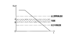
- FIG. 2 shows the transition of the engine rotation speed Ne during the rotation drop period until the combustion of the engine 11 is stopped and the engine rotation speed Ne becomes zero.
- the engine rotation speed Ne passes through a self-recovery return rotation speed, an engine resonance range, and a predetermined rotation speed set in advance (for example, about 200 rpm).
- the self-recovery return rotational speed is a lower limit of the rotational speed at which the engine can be restarted by restarting the fuel supply without cranking while the combustion of the engine 11 is stopped, and is set to about 500 rpm, for example. .
- the engine resonance region refers to the region of the engine speed at which resonance occurs, and is set to 300 to 400 rpm, for example.
- resonance is a phenomenon that is excited when the excitation frequency corresponding to the engine rotation speed matches the resonance frequency of a power plant such as an engine body or an automatic transmission. Due to this phenomenon, vibration increases in the resonance region of the engine. Thus, the vibration in the resonance region is one factor of unpleasant vibration that occurs when the engine stops.
- the resonance region of the engine is provided on the lower rotation side than the idle rotation speed and on the higher rotation side than the cranking rotation speed of the conventional starter so that vibration due to resonance does not occur as much as possible. Therefore, after the combustion of the engine is stopped, the engine rotation speed Ne passes through the resonance region in the rotation descent period until the engine rotation speed Ne reaches zero.
- This embodiment shows the engine control in the rotation descent period until the combustion of the engine 11 is stopped and the engine rotation speed Ne becomes zero.
- the rotation descent period is divided into three periods based on the engine speed Ne. That is, the period from when the combustion of the engine 11 stops until the engine rotational speed Ne reaches the upper limit value of the predetermined rotational speed region including the resonance region (specifically, the boundary value A on the high rotation side of the resonance region).
- the first period is the second period when the engine rotation speed Ne is in the specified rotation speed range, and the engine rotation speed Ne is the lower limit value of the predetermined rotation speed range (specifically, the boundary value on the low rotation side of the resonance range).
- the period from the passage of B) until the engine speed Ne becomes zero was defined as the third period.
- engine control is performed according to each period.
- the opening of the throttle valve 22 is set to an opening larger than the idle rotation state. As a result, the amount of air necessary for restarting the engine is secured.
- a rotation descent process for increasing the descent speed of the engine rotation speed Ne in a predetermined rotation speed range including the resonance range is performed.
- the time for passing through the resonance region can be shortened, and vibrations caused by the resonance region can be suppressed.
- reverse rotation side torque (reverse torque) is applied to the crankshaft 14 so that the piston 13 is stopped at the crank rotation position in the first half of the expansion stroke when the rotation of the crankshaft 14 is stopped.
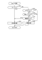
- FIG. 3 is a flowchart showing a processing procedure for engine control, and this processing is repeatedly executed by the ECU 50 at a predetermined cycle (for example, 10 ms).
- the first flag, the second flag, and the third flag in the figure correspond to the first period, the second period, and the third period, respectively, and whether or not the engine speed Ne belongs to each period. It is a flag which shows. Each flag indicates that the engine speed Ne belongs to the period when “1”, and does not belong to the period when “0”. In the initial setting, both are set to “0”.
- step S11 it is determined whether or not the third flag is “1”.
- step S12 it is determined whether or not the second flag is “1”.
- step S13 it is determined whether or not the first flag is “1”. If the determination in step S11 to step S13 is negative in the initial state, the process proceeds to step S14 to determine whether or not the engine automatic stop condition is satisfied. And when step S14 is denied, this process is complete
- step S14 determines whether the engine automatic stop condition is satisfied. If it is determined in step S14 that the engine automatic stop condition is satisfied, the process proceeds to step S15, and "1" is set to the first flag. In the subsequent step S16, the combustion of the engine 11 is stopped, and the process proceeds to step S17.
- step S17 the opening of the throttle valve 22 is set to an opening larger than the opening in the idle rotation state (specifically, the opening is set to + 10% or more with respect to the opening in the idle rotation state, for example, This process is terminated.
- step S17 corresponds to a throttle control unit.
- step S18 in which it is determined whether or not the engine rotational speed Ne is equal to or lower than a predetermined rotational speed Ne1 that is an upper limit value of the predetermined rotational speed range.
- the boundary value A on the high rotation side of the resonance region is set as the predetermined rotation speed Ne1. That is, in step S18, it is determined whether or not the engine rotation speed Ne has reached the boundary value A on the high rotation side of the resonance region.
- step S18 If it is determined in step S18 that the engine rotational speed Ne is greater than the predetermined rotational speed Ne1, this process is terminated. On the other hand, if it is determined in step S18 that the engine rotational speed Ne is equal to or lower than the predetermined rotational speed Ne1, that is, if the engine rotational speed Ne has shifted to the resonance range, the process proceeds to step S19, and the second flag is set to “1”. At the same time, the first flag is reset to “0”.
- step S20 first, reverse torque is set.
- the MG30 has a power generation function as a generator and a power running function as an electric motor, and applying reverse torque is executed using each function.
- the power running drive has a larger reverse torque than the regenerative power generation, and the regenerative power generation is superior in terms of fuel consumption compared to the power running drive. Therefore, it is desirable to use each function properly according to the driving state. In such a case, which function is used is determined based on various parameters.
- the MG 30 depends on the amount of power consumed by the electrical load 36 connected to the battery 35, the state of the remaining capacity of the battery 35, the amount of torque required to apply reverse torque, and the load due to the operation of the auxiliary machine 16. The regenerative power generation and power running drive are selected.
- Fig. 4 shows a flowchart of reverse torque setting.
- step S31 it is determined whether the power consumption of the electrical load 36 is equal to or greater than a predetermined value.
- the electric load 36 include lamps and an electric pump. More specifically, it is determined whether or not the brake pedal is depressed. When the brake pedal is depressed, the brake lamp is lit, and the power consumption is increased. If it is determined in step S31 that the brake pedal is depressed, the process proceeds to step S32, and it is determined to apply reverse torque by regenerative power generation. In this case, since the amount of power consumed by the electric load 36 is large, vibration can be suppressed while reducing the burden on the battery 35 by using regenerative power generation.
- step S31 determines whether or not the SOC of the battery 35 is greater than or equal to the threshold Th1. If it is determined in step S33 that the SOC is equal to or greater than the threshold value Th1, the process proceeds to step S36, and it is determined to apply reverse torque by powering drive.
- the value of the threshold Th1 may be changed as appropriate. For example, when the threshold Th1 is equal to or greater than the threshold Th1, it may be a value that can be determined to be a fully charged state.
- an estimation method based on an open circuit voltage (OCV) and a calculation method based on current integration are used.
- OCV open circuit voltage
- the SOC is estimated using the acquired value and a map representing the correspondence relationship between the open-circuit voltage and the SOC, and the charge / discharge current flowing through the battery 35 is acquired.
- the SOC is calculated by calculating the obtained value.
- reverse torque by power running drive it is good also as a setting which makes reverse torque large, so that electric remaining amount is large. In this case, it is considered that the passing time through the resonance region can be further shortened and the vibration suppressing effect is enhanced.
- step S33 when step S33 is denied, it progresses to step S34 and a function is selected according to the request
- step S34 the process proceeds to step S35, and a function is selected according to the load of the auxiliary machine 16. For example, it is determined whether or not the load due to the operation of the auxiliary machine 16 is greater than or equal to the threshold Th3. When it determines with it being more than threshold value Th3 by step S35, it progresses to step S32 and determines providing reverse torque by regenerative power generation. In such a case, the power consumption of the electric load 36 is less than a predetermined value (step S31: NO), but regenerative power generation is selected in view of other parameters indicating the driving state of the vehicle.
- step S35 when step S35 is denied, it progresses to step S36 and determines giving reverse torque by power running drive. As described above, after regenerative power generation or power running drive is determined based on the parameters, the process proceeds to step S21 in FIG. 3 to apply reverse torque.
- step S31 when step S31 is NO, it may be configured to proceed to step S36 without selecting the determination of step S33 to step S35 and select power running drive. That is, when the electric power consumption of the electric load 36 is less than a predetermined value, a configuration in which reverse torque is applied by power running drive may be used.
- the application of reverse torque by power running drive corresponds to the first rotation descent process
- the application of reverse torque by regenerative power generation corresponds to the second rotation descent process
- step S12 of FIG. 3 determines whether the second flag is “1”
- the process proceeds to step S22, and whether the engine rotational speed Ne is smaller than the predetermined rotational speed Ne2 that is the lower limit value of the predetermined rotational speed range. Determine whether or not.
- the boundary value B on the low rotation side of the resonance region is set as the predetermined rotation speed Ne2. That is, in step S22, it is determined whether or not the engine rotation speed Ne has passed the boundary value B on the low rotation side of the resonance region.
- step S22 If it is determined in step S22 that the engine rotational speed Ne is smaller than the predetermined rotational speed Ne2, that is, if the engine rotational speed Ne has shifted to the third period, the process proceeds to step S23, and the third flag is set to “1”. At the same time, the second flag is reset to “0”. In subsequent step S24, the reverse torque applied in step S21 is stopped. On the other hand, if it is determined in step S22 that the engine rotational speed Ne is equal to or higher than the predetermined rotational speed Ne2, the present process is terminated.
- step S18 and step S22 corresponds to a resonance region determination unit that determines that the engine passes the resonance region.
- the process of step S20 and step S21 is equivalent to a rotation descent control part.
- reverse torque is provided to an engine output shaft by using properly the power running drive and regenerative power generation of a rotary electric machine.
- step S11 determines whether the third flag is “1”
- the process proceeds to step S25 to execute the subroutine shown in FIG. That is, when the engine speed Ne shifts to the third period, the crank angle stop process for suppressing the reverse rotation of the engine is performed.
- reverse torque is applied at a predetermined timing based on the engine speed so that the piston 13 is stopped at the first half of the expansion stroke, that is, the piston 13 of the next combustion cylinder is stopped at the first half of the compression stroke.
- a backup process for applying a torque (forward torque) on the forward rotation side to the engine output shaft is also executed. That is, in the crank angle stop process, control is performed so that the piston 13 does not stop at the latter half of the compression stroke, that is, the piston 13 does not stop at the position where the compression reaction force is generated.
- step S41 of FIG. 5 it is first determined whether or not it is time to apply a positive torque to the engine output shaft. This step is affirmed when it is determined that the backup process is to be executed, and step S41 is denied in the initial setting.
- step S42 it is determined whether or not it is time to apply a reverse torque to the engine output shaft. In the present embodiment, for example, when the engine rotation speed Ne when the piston 13 is positioned at the compression TDC is equal to or lower than the predetermined rotation speed Ne3, it is determined that it is the timing to apply the reverse torque. If it is determined that it is time to apply reverse torque, the process proceeds to step S43, where reverse torque is applied to the engine output shaft, and this process ends.
- the predetermined rotational speed Ne3 is determined to stop rotation of the engine output shaft by applying reverse torque from the timing when the piston is positioned at the compression TDC until the piston passes the first half of the expansion stroke. Rotation speed.
- the predetermined rotational speed Ne3 is set to a value smaller than the predetermined rotational speed Ne2 that is the lower limit value of the predetermined rotational speed range.
- step S42 determines whether or not the timing to apply the reverse torque.
- step S44 determines whether or not the reverse torque is applied.
- step S44 determines whether the reverse torque is applied
- the process proceeds to step S45, where the crank rotational position detected by the crank angle sensor 51 is set to a predetermined angle (for example, ATDC 70 ° CA). It is determined whether or not. If it is determined that the rotational position is the predetermined angle, the process proceeds to step S46, and it is determined whether or not the engine rotational speed Ne is equal to or lower than the predetermined rotational speed Ne4. On the other hand, when step S45 is denied, this process is complete
- a predetermined angle for example, ATDC 70 ° CA
- step S46 If it is determined in step S46 that the engine rotational speed Ne is equal to or lower than the predetermined rotational speed Ne4, that is, if it is determined that the piston 13 stops in the first half of the expansion stroke, the process proceeds to step S47, and is given in step S43. Instructs to stop reverse torque. As a result, the reverse torque applied to the engine output shaft is stopped. Then, it progresses to step S48, a 3rd flag is reset to "0", and this process is complete
- step S45 and step S46 are equivalent to a stop determination part.
- the predetermined rotational speed Ne4 at the predetermined angle can be arbitrarily changed, and can be determined whether or not the piston 13 actually stops at the crank rotational position until the first half of the expansion stroke after applying the reverse torque in step S43. If it is.
- step S46 determines whether the engine rotational speed Ne is greater than the predetermined rotational speed Ne4 or not stop at the first half of the expansion stroke. That is, it is determined that the backup process is executed.
- this process is executed and the crank rotational position is at a predetermined rotational angle (for example, ATDC 90 ° CA), it is determined that it is time to apply a positive torque to the engine output shaft (step) S41: YES).
- step S41 If step S41 is affirmed, the process proceeds to step S50, a positive torque is applied, and the process is terminated. Thereafter, the process proceeds to step S42 again, and the crank angle stop process is executed until the third flag is finally reset to “0”.
- the first flag is set to “1”.
- the opening degree of the throttle valve 22 is controlled to be larger than the opening degree in the idle state.
- the second flag is set to “1” and at the same time the first flag is reset to “0”.
- a reverse torque is applied to the engine output shaft as a rotation descent process.
- the third flag is set to “1” and at the same time the second flag is reset to “0”.
- the rotation descent process is stopped, and the crank angle stop process is executed in the subsequent third period.
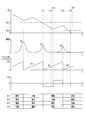
- the timing t14 the engine rotational speed Ne becomes zero.
- FIGS. 7 shows a case where step S46 is affirmed and only reverse torque is applied in the third period
- FIG. 8 shows that step S46 is negated and positive torque is applied in addition to reverse torque in the third period. Shows the case.
- changes in the in-cylinder pressure of each cylinder are shown. The in-cylinder pressure increases as the piston 13 approaches the compression TDC, and becomes maximum at the compression TDC. Further, the maximum value of the in-cylinder pressure decreases as the engine speed Ne decreases. Note that the firing order of each cylinder is # 1 ⁇ # 2 ⁇ # 3 ⁇ # 4 for convenience of explanation.
- a four-cylinder engine is shown as a multi-cylinder engine.
- the piston 13 of one cylinder stops at the position of the first half period of the expansion stroke
- the piston 13 of the other cylinder does not stop at the position of the second half period of the compression stroke, that is, the position where the compression reaction force is generated.
- the opening of the throttle valve 22 is set to an opening larger than the opening in the idle rotation state, which is necessary when the engine is restarted. A sufficient amount of air can be secured. Further, by applying the reverse torque using the MG 30 so that the decrease rate of the engine rotation speed is increased in the resonance region, it is possible to shorten the time for passing through the resonance region. In this case, in a state where the throttle opening is large, there is a concern about an increase in vibration in the resonance region, but an increase in vibration can be suppressed by reducing the passage time of the resonance region. As a result, in a vehicle having an idling stop function, it is possible to ensure startability at the time of restart while suppressing generation of vibration at the time of automatic engine stop.
- the throttle valve 22 is configured to have an opening larger than the opening in the idle rotation state. Therefore, even when the restart condition is satisfied immediately after the combustion is stopped, a sufficient amount of air can be secured and the startability at the time of restart is improved.
- a reverse torque is applied using MG30.
- the regenerative power generation and the power running drive can be selected.
- the power running drive has a larger reverse torque than the regenerative power generation, and the regenerative power generation is superior in terms of fuel consumption compared to the power running drive.
- the regenerative power generation and the power running drive can be selected according to the power consumption of the electric load 36 connected to the battery 35.
- the battery 35 is burdened and reverse torque is applied by regenerative power generation. Thereby, it is possible to suppress vibration while keeping the power state of the battery 35 stable.
- the regenerative power generation and the power running driving can be selected based on the remaining electric power of the battery 35.
- the threshold value Th1 when the remaining amount of electricity is equal to or greater than the threshold value Th1, reverse torque is applied by powering drive.
- the remaining amount of electricity in the battery 35 is large, there is a concern about overcharging of the battery 35 by causing the rotating electric machine to generate regenerative power.
- by applying the reverse torque by powering drive it is possible to suppress vibration caused by the resonance region without damaging the battery 35.
- the MG 30 is used to apply reverse torque from the compression top dead center.
- the piston 13 can be stopped at the first half of the expansion stroke by applying reverse torque. Thereby, the vibration accompanying it can be reduced by suppressing generation
- the engine 11 is determined to be the previous compression top dead center based on the engine rotation speed at the compression top dead center being equal to or less than a predetermined value.
- the predetermined value is a value that is determined by stopping the piston 13 at the first half of the expansion stroke by applying reverse torque. Therefore, the piston 13 can be stopped at a desired position, and the vibration accompanying the reverse rotation of the engine can be reduced.
- a stop determination unit that determines whether or not the piston 13 actually stops at a desired position is provided, and when it is determined to stop at the desired position, the reverse torque application is stopped. It was. In this case, when the rotation of the engine stops at the first half of the expansion stroke, the application of reverse torque is released. Thereby, reverse rotation of the engine due to reverse torque can be prevented.
- backup processing was provided for stop control in the third period. That is, when the stop determination unit determines that the piston 13 does not stop at a desired position, a positive torque is once applied so that the piston 13 can get over the next compression TDC. Then, when the compression TDC is reached, a reverse torque is applied again to stop the piston at the first half of the expansion stroke. Thereby, the piston 13 can be more reliably stopped at the first half of the expansion stroke, and the vibration suppressing effect can be enhanced.
- the reverse torque is applied in the resonance region using the MG 30, and the reverse torque by the crank stop process is applied in the third period, or Forward / reverse torque was applied.
- the vibration accompanying the reverse rotation of the engine can be suppressed.
- the adverse effect of the vibration in the resonance region on the reverse rotation vibration is reduced.
- the vibration generated between the stop of the combustion of the engine 11 and the stop of the rotation of the engine 11 is synergistically. Can be suppressed.
- the MG30 is used as an auxiliary device to apply reverse torque, but any auxiliary device that can apply reverse torque to the engine output shaft may be used.
- the auxiliary equipment include auxiliary equipment 16 such as a water pump and a fuel pump. In this case, even in a vehicle not equipped with the MG 30, reverse torque can be applied using a device that is normally provided in the vehicle. For this reason, there is no need to provide a new device separately, which is economical.
- the reverse torque is applied with the predetermined rotation speed range as the resonance range. That is, the upper limit value of the predetermined rotation speed range is set as the boundary value A on the high rotation side of the resonance range, and the lower limit value of the predetermined rotation speed range is set as the boundary value B on the low rotation side of the resonance range.
- the predetermined rotational speed region may be configured so as to include the resonance region.
- the predetermined rotational speed region may be determined by setting the predetermined rotational speed higher than the resonance region as the upper limit value.
- step S18 of FIG. 3 it is determined whether or not the engine rotational speed Ne is equal to or lower than a predetermined rotational speed Ne1 set higher than the boundary value A of the resonance region, and step S18 is YES. If so, the application of reverse torque is started.
- the reverse torque is applied before reaching the resonance range, thereby improving the response to the descending speed due to the reverse torque near the boundary value A in the resonance range. Can do. As a result, the passage time of the resonance region is further shortened, and the vibration suppressing effect is enhanced.
- the predetermined rotational speed range may be determined with the self-recovery return rotational speed higher than the resonance area as the upper limit value.
- step S18 of FIG. 3 it is determined whether or not the engine rotational speed Ne is equal to or lower than the predetermined rotational speed Ne1 set to the self-recovery return rotational speed. If step S18 is YES, reverse torque is applied. Start.
- the engine rotational speed Ne1 exceeds the predetermined rotation speed Ne1 at the beginning when the engine starts to stop combustion, the decrease speed of the engine rotation speed is not increased, and the possibility of the engine self-recovery is possible. Can be expected. As a result, the power consumption required for restart can be reduced, the response to the descent speed in the resonance region can be improved, and the vibration suppression effect can be enhanced.
- the predetermined rotational speed range may be determined by setting a predetermined rotational speed set in advance on the lower rotation side than the resonance range as a lower limit value.
- step S22 of FIG. 3 it is determined whether or not the engine rotational speed Ne is lower than a predetermined rotational speed Ne2, and if step S22 is YES, the application of reverse torque is stopped.
- step S22 it is possible to expect the possibility of restarting the engine due to cranking without increasing the decrease rate of the engine rotation speed while the engine rotation speed is between a predetermined rotation speed set in advance and zero. .
- restartability can be ensured while suppressing vibration in the resonance region.
- the predetermined rotational speed range may be set by combining the setting of the upper limit value and the lower limit value of the predetermined rotational speed range described above. For example, it is possible to set the upper limit value of the predetermined rotation speed range to a self-recovery return rotation speed higher than the resonance range and the lower limit value to a predetermined rotation speed set in advance on the lower rotation side than the resonance range. In such a case, it is possible to pass through the rotational speed region where the engine cannot be restarted at an early stage by means of fuel supply or cranking. On the other hand, in the region where the engine can be restarted, the decrease speed of the engine speed is not increased. As a result, restartability can be ensured while suppressing vibration in the resonance region.
- the power consumption of the electrical load 36 connected to the battery 35 the state of the remaining capacity of the battery 35, the required torque amount required for the reverse torque application, and the auxiliary machine 16
- the regenerative power generation and the power running drive of the MG 30 are selected according to the load caused by the operation of the above, but the configuration may be selected according to other parameters. Other parameters include the rotational speed of the MG 30 and the like.
- priority may be set between the above parameters. For example, the determination based on the driving state of the electric load 36 may be given the highest priority, followed by the state of the remaining capacity of the battery 35, the required torque amount necessary for applying reverse torque, and the load due to the operation of the auxiliary machine 16.
- the SOC of the battery 35 is used as the state of the remaining capacity of the battery 35.
- the present invention is not limited to this.
- the voltage between the terminals of the battery 35 may be used.
- the reverse torque is applied from the timing t31 to the timing t33 in FIG. 8, but the reverse torque is stopped at the time of the stop determination at the timing t32. Good.
- a positive torque is applied from the timing t33 to the timing t34 (timing when the second cylinder (# 2) reaches the compression TDC).
- the period for applying the positive torque is not limited to this, and any structure may be used as long as the positive torque is applied so that the piston (here, the second cylinder (# 2)) can overcome the compression TDC.
- the configuration may be such that positive torque application is stopped.
- the magnitude of the reverse torque applied in the crank angle stop process may be determined in advance as the amount of torque required to stop the piston 13 at the first half of the expansion stroke. Also, means for predicting the stop position of the piston 13 every moment when the rotation of the engine stops is provided, and even if reverse torque is applied while performing feedback control for adjusting the torque amount based on the predicted stop position. Good.
- the magnitudes of the reverse torque and the positive torque applied in the crank angle stop process may be appropriately changed, and may be the same torque amount or different torque amounts. Further, the magnitudes of the first reverse torque and the second reverse torque when the backup process is performed may be appropriately changed. For example, the second reverse torque may be made larger than the first reverse torque, and according to this configuration, it is considered that the piston can be more reliably stopped at a desired position.
- the crank angle position at which the predetermined rotation speed Ne3 is set is not limited to the compression TDC, and the engine rotation speed Ne at other crank angle positions may be set as a threshold value for determination.
- the application of reverse torque may be started from the crank angle position at which the threshold is set.
- the predetermined rotation speed Ne3 is provided as a threshold value for the engine rotation speed as the determination of the timing for applying the reverse torque.
- the present invention is not limited to this method.
- a method may be used in which the timing is determined from the decrease in the engine rotational speed Ne.
- the ECU 50 calculates the rotational speed drop amount ⁇ Ne from the engine rotational speed Ne for each compression TDC, and estimates the compression TDC (i) that is predicted to be less than zero.
- the timing at which the compression TDC (i ⁇ 1) immediately before the compression TDC (i) is reached can be set as the reverse torque application timing.
- the above-described control during the rotation descent period until the engine rotation speed becomes zero is not limited to the automatic engine stop, but may be performed in the case of a stop by the driver's ignition switch operation. Moreover, the case of the stop in the vehicle which does not have an idling stop function may be sufficient.
Landscapes
- Engineering & Computer Science (AREA)
- Chemical & Material Sciences (AREA)
- Combustion & Propulsion (AREA)
- Mechanical Engineering (AREA)
- Transportation (AREA)
- Automation & Control Theory (AREA)
- General Engineering & Computer Science (AREA)
- Power Engineering (AREA)
- Control Of Vehicle Engines Or Engines For Specific Uses (AREA)
- Hybrid Electric Vehicles (AREA)
- Electric Propulsion And Braking For Vehicles (AREA)
- Output Control And Ontrol Of Special Type Engine (AREA)
Priority Applications (3)
| Application Number | Priority Date | Filing Date | Title |
|---|---|---|---|
| CN201780028876.9A CN109072790B (zh) | 2016-05-10 | 2017-04-27 | 发动机控制装置 |
| US16/301,152 US10906527B2 (en) | 2016-05-10 | 2017-04-27 | Engine control apparatus |
| DE112017002432.3T DE112017002432T5 (de) | 2016-05-10 | 2017-04-27 | Kraftmaschinensteuerungsvorrichtung |
Applications Claiming Priority (2)
| Application Number | Priority Date | Filing Date | Title |
|---|---|---|---|
| JP2016-094755 | 2016-05-10 | ||
| JP2016094755A JP6642255B2 (ja) | 2016-05-10 | 2016-05-10 | エンジン制御装置 |
Publications (1)
| Publication Number | Publication Date |
|---|---|
| WO2017195627A1 true WO2017195627A1 (ja) | 2017-11-16 |
Family
ID=60267046
Family Applications (1)
| Application Number | Title | Priority Date | Filing Date |
|---|---|---|---|
| PCT/JP2017/016759 Ceased WO2017195627A1 (ja) | 2016-05-10 | 2017-04-27 | エンジン制御装置 |
Country Status (5)
| Country | Link |
|---|---|
| US (1) | US10906527B2 (enExample) |
| JP (1) | JP6642255B2 (enExample) |
| CN (1) | CN109072790B (enExample) |
| DE (1) | DE112017002432T5 (enExample) |
| WO (1) | WO2017195627A1 (enExample) |
Cited By (1)
| Publication number | Priority date | Publication date | Assignee | Title |
|---|---|---|---|---|
| CN110091861A (zh) * | 2018-01-30 | 2019-08-06 | 爱信精机株式会社 | 车辆控制器 |
Families Citing this family (9)
| Publication number | Priority date | Publication date | Assignee | Title |
|---|---|---|---|---|
| JP2017203402A (ja) * | 2016-05-10 | 2017-11-16 | 株式会社デンソー | エンジン制御装置 |
| JP2019162950A (ja) * | 2018-03-20 | 2019-09-26 | 株式会社デンソー | エンジン制御システム |
| JP7052542B2 (ja) * | 2018-05-08 | 2022-04-12 | 株式会社デンソー | エンジンの停止制御装置 |
| DE102018112254A1 (de) * | 2018-05-22 | 2019-11-28 | Bayerische Motoren Werke Aktiengesellschaft | Kontrollsystem für ein Kraftfahrzeug, Kraftfahrzeug, Verfahren zur Kontrolle eines Kraftfahrzeugs, Computerprogrammprodukt und computerlesbares Medium |
| JP7070240B2 (ja) * | 2018-08-23 | 2022-05-18 | トヨタ自動車株式会社 | ハイブリッド車両 |
| JP7293626B2 (ja) * | 2018-12-04 | 2023-06-20 | スズキ株式会社 | エンジン停止補助装置 |
| US11177762B2 (en) * | 2019-02-20 | 2021-11-16 | Volvo Car Corporation | Electric motor control for preventing torque ripple |
| JP2021138242A (ja) * | 2020-03-04 | 2021-09-16 | 本田技研工業株式会社 | ハイブリッド車両およびその廃電制御方法 |
| JP2021154853A (ja) * | 2020-03-26 | 2021-10-07 | 本田技研工業株式会社 | ハイブリッド車両の制御装置 |
Citations (5)
| Publication number | Priority date | Publication date | Assignee | Title |
|---|---|---|---|---|
| JPH11332297A (ja) * | 1998-05-15 | 1999-11-30 | Hitachi Ltd | 電気車の制御装置および制御方法 |
| JP2001207885A (ja) * | 2000-01-27 | 2001-08-03 | Toyota Motor Corp | ハイブリッド車両の内燃機関停止制御装置 |
| JP2002305807A (ja) * | 2001-04-03 | 2002-10-18 | Isuzu Motors Ltd | エンジン停止制御装置 |
| JP2006064152A (ja) * | 2004-08-30 | 2006-03-09 | Toyota Motor Corp | 車両の減速度制御装置 |
| JP2011245948A (ja) * | 2010-05-25 | 2011-12-08 | Kawasaki Heavy Ind Ltd | 建設機械及びその制御方法 |
Family Cites Families (12)
| Publication number | Priority date | Publication date | Assignee | Title |
|---|---|---|---|---|
| FR1593562A (enExample) * | 1968-08-12 | 1970-06-01 | ||
| JPH0742939B2 (ja) * | 1985-10-07 | 1995-05-15 | 株式会社日立製作所 | トルク制御式圧縮機 |
| JP3631036B2 (ja) * | 1999-03-09 | 2005-03-23 | 本田技研工業株式会社 | ハイブリッド車両のエンジン制御装置 |
| JP4147398B2 (ja) * | 2003-04-25 | 2008-09-10 | 三菱自動車工業株式会社 | エンジン制御装置 |
| US7383115B2 (en) | 2004-08-30 | 2008-06-03 | Toyota Jidosha Kabushiki Kaisha | Vehicle deceleration control apparatus |
| JP4784478B2 (ja) * | 2006-04-20 | 2011-10-05 | 株式会社デンソー | 多相回転電機の制御装置 |
| JP4577326B2 (ja) * | 2007-04-04 | 2010-11-10 | 株式会社デンソー | 内燃機関の停止制御装置及び停止制御システム |
| JP2009204065A (ja) * | 2008-02-27 | 2009-09-10 | Nissan Motor Co Ltd | 車両のエンジン制御装置及びエンジン制御方法 |
| JP5746880B2 (ja) | 2011-02-21 | 2015-07-08 | ダイハツ工業株式会社 | 内燃機関の制御装置 |
| CN103827467A (zh) * | 2011-09-21 | 2014-05-28 | 丰田自动车株式会社 | 车辆和车辆用控制方法 |
| JP6294812B2 (ja) | 2014-11-14 | 2018-03-14 | エバ工業株式会社 | 工場建物の換気システムおよび換気方法 |
| EP3386080B1 (en) * | 2015-11-30 | 2022-11-23 | Limin Xu | Homopolar direct current electromagnetic motor and application system thereof |
-
2016
- 2016-05-10 JP JP2016094755A patent/JP6642255B2/ja not_active Expired - Fee Related
-
2017
- 2017-04-27 CN CN201780028876.9A patent/CN109072790B/zh not_active Expired - Fee Related
- 2017-04-27 DE DE112017002432.3T patent/DE112017002432T5/de not_active Withdrawn
- 2017-04-27 WO PCT/JP2017/016759 patent/WO2017195627A1/ja not_active Ceased
- 2017-04-27 US US16/301,152 patent/US10906527B2/en not_active Expired - Fee Related
Patent Citations (5)
| Publication number | Priority date | Publication date | Assignee | Title |
|---|---|---|---|---|
| JPH11332297A (ja) * | 1998-05-15 | 1999-11-30 | Hitachi Ltd | 電気車の制御装置および制御方法 |
| JP2001207885A (ja) * | 2000-01-27 | 2001-08-03 | Toyota Motor Corp | ハイブリッド車両の内燃機関停止制御装置 |
| JP2002305807A (ja) * | 2001-04-03 | 2002-10-18 | Isuzu Motors Ltd | エンジン停止制御装置 |
| JP2006064152A (ja) * | 2004-08-30 | 2006-03-09 | Toyota Motor Corp | 車両の減速度制御装置 |
| JP2011245948A (ja) * | 2010-05-25 | 2011-12-08 | Kawasaki Heavy Ind Ltd | 建設機械及びその制御方法 |
Cited By (1)
| Publication number | Priority date | Publication date | Assignee | Title |
|---|---|---|---|---|
| CN110091861A (zh) * | 2018-01-30 | 2019-08-06 | 爱信精机株式会社 | 车辆控制器 |
Also Published As
| Publication number | Publication date |
|---|---|
| CN109072790A (zh) | 2018-12-21 |
| US20190210590A1 (en) | 2019-07-11 |
| US10906527B2 (en) | 2021-02-02 |
| CN109072790B (zh) | 2022-04-05 |
| JP6642255B2 (ja) | 2020-02-05 |
| JP2017202726A (ja) | 2017-11-16 |
| DE112017002432T5 (de) | 2019-01-24 |
Similar Documents
| Publication | Publication Date | Title |
|---|---|---|
| JP6642255B2 (ja) | エンジン制御装置 | |
| US7840337B2 (en) | Method for controlling an overrun condition of a hybrid vehicle and hybrid vehicle | |
| JP4075699B2 (ja) | 車両の制御装置 | |
| JP5910211B2 (ja) | 車両搭載エンジンの始動装置 | |
| JP6620668B2 (ja) | エンジン制御装置 | |
| JP2006214332A (ja) | 内燃機関の制御装置及びその制御装置を備えた自動車 | |
| US11136930B2 (en) | Engine start control device | |
| WO2017195630A1 (ja) | エンジン制御装置 | |
| WO2017195629A1 (ja) | エンジン停止始動制御装置 | |
| JP4165237B2 (ja) | 内燃機関の始動制御装置 | |
| JP2013124082A (ja) | ハイブリッド電気自動車の制御装置 | |
| JP6891486B2 (ja) | ハイブリッド車両の駆動制御装置 | |
| JP7292789B2 (ja) | 車両制御装置 | |
| JP7733616B2 (ja) | モータ制御装置、およびモータ制御方法 | |
| JP7786528B1 (ja) | 電動車両 | |
| US20230303075A1 (en) | Vehicle controller and method for controlling vehicle | |
| WO2015159876A1 (ja) | 車両用制御装置 | |
| JP2025126666A (ja) | 車両の制御装置 | |
| JP2004332681A (ja) | 車両のエンジン始動装置 |
Legal Events
| Date | Code | Title | Description |
|---|---|---|---|
| 121 | Ep: the epo has been informed by wipo that ep was designated in this application |
Ref document number: 17795988 Country of ref document: EP Kind code of ref document: A1 |
|
| 122 | Ep: pct application non-entry in european phase |
Ref document number: 17795988 Country of ref document: EP Kind code of ref document: A1 |