WO2017187881A1 - 運転支援システム - Google Patents
運転支援システム Download PDFInfo
- Publication number
- WO2017187881A1 WO2017187881A1 PCT/JP2017/013346 JP2017013346W WO2017187881A1 WO 2017187881 A1 WO2017187881 A1 WO 2017187881A1 JP 2017013346 W JP2017013346 W JP 2017013346W WO 2017187881 A1 WO2017187881 A1 WO 2017187881A1
- Authority
- WO
- WIPO (PCT)
- Prior art keywords
- magnetic
- vehicle
- information
- marker
- magnetic marker
- Prior art date
Links
- 239000003550 marker Substances 0.000 claims description 270
- 238000009434 installation Methods 0.000 claims description 24
- 230000005389 magnetism Effects 0.000 claims description 9
- 239000006247 magnetic powder Substances 0.000 claims description 7
- 230000002093 peripheral effect Effects 0.000 claims description 4
- 230000006854 communication Effects 0.000 description 39
- 238000004891 communication Methods 0.000 description 38
- 238000001514 detection method Methods 0.000 description 17
- 230000005540 biological transmission Effects 0.000 description 15
- 238000000034 method Methods 0.000 description 15
- 239000011347 resin Substances 0.000 description 15
- 229920005989 resin Polymers 0.000 description 15
- 230000004907 flux Effects 0.000 description 11
- 230000008859 change Effects 0.000 description 8
- 238000012545 processing Methods 0.000 description 8
- UQSXHKLRYXJYBZ-UHFFFAOYSA-N Iron oxide Chemical compound [Fe]=O UQSXHKLRYXJYBZ-UHFFFAOYSA-N 0.000 description 6
- 230000005674 electromagnetic induction Effects 0.000 description 6
- 230000008569 process Effects 0.000 description 6
- 230000004308 accommodation Effects 0.000 description 5
- 239000011230 binding agent Substances 0.000 description 5
- 238000010586 diagram Methods 0.000 description 5
- 230000000694 effects Effects 0.000 description 5
- 239000000945 filler Substances 0.000 description 5
- 230000006870 function Effects 0.000 description 5
- 239000004033 plastic Substances 0.000 description 5
- 229920003023 plastic Polymers 0.000 description 5
- 239000002994 raw material Substances 0.000 description 4
- 230000035945 sensitivity Effects 0.000 description 4
- 238000004088 simulation Methods 0.000 description 4
- 238000003860 storage Methods 0.000 description 4
- 229910000859 α-Fe Inorganic materials 0.000 description 4
- 230000003247 decreasing effect Effects 0.000 description 3
- 238000006073 displacement reaction Methods 0.000 description 3
- 239000004744 fabric Substances 0.000 description 3
- 230000001771 impaired effect Effects 0.000 description 3
- 239000010410 layer Substances 0.000 description 3
- 239000000696 magnetic material Substances 0.000 description 3
- 239000004745 nonwoven fabric Substances 0.000 description 3
- 238000010422 painting Methods 0.000 description 3
- -1 polyethylene Polymers 0.000 description 3
- 230000004044 response Effects 0.000 description 3
- 239000004065 semiconductor Substances 0.000 description 3
- 239000002759 woven fabric Substances 0.000 description 3
- RYGMFSIKBFXOCR-UHFFFAOYSA-N Copper Chemical compound [Cu] RYGMFSIKBFXOCR-UHFFFAOYSA-N 0.000 description 2
- PXHVJJICTQNCMI-UHFFFAOYSA-N Nickel Chemical compound [Ni] PXHVJJICTQNCMI-UHFFFAOYSA-N 0.000 description 2
- 239000004698 Polyethylene Substances 0.000 description 2
- 239000004743 Polypropylene Substances 0.000 description 2
- BQCADISMDOOEFD-UHFFFAOYSA-N Silver Chemical compound [Ag] BQCADISMDOOEFD-UHFFFAOYSA-N 0.000 description 2
- 239000000853 adhesive Substances 0.000 description 2
- 230000001070 adhesive effect Effects 0.000 description 2
- 238000010276 construction Methods 0.000 description 2
- 229910052802 copper Inorganic materials 0.000 description 2
- 239000010949 copper Substances 0.000 description 2
- 230000007423 decrease Effects 0.000 description 2
- 238000009826 distribution Methods 0.000 description 2
- 238000011049 filling Methods 0.000 description 2
- 239000011521 glass Substances 0.000 description 2
- 239000003365 glass fiber Substances 0.000 description 2
- 238000002156 mixing Methods 0.000 description 2
- 229920000573 polyethylene Polymers 0.000 description 2
- 229920000139 polyethylene terephthalate Polymers 0.000 description 2
- 239000005020 polyethylene terephthalate Substances 0.000 description 2
- 229920001155 polypropylene Polymers 0.000 description 2
- 238000007639 printing Methods 0.000 description 2
- 230000002829 reductive effect Effects 0.000 description 2
- 229910052709 silver Inorganic materials 0.000 description 2
- 239000004332 silver Substances 0.000 description 2
- 229920002799 BoPET Polymers 0.000 description 1
- OKTJSMMVPCPJKN-UHFFFAOYSA-N Carbon Chemical compound [C] OKTJSMMVPCPJKN-UHFFFAOYSA-N 0.000 description 1
- 229920000049 Carbon (fiber) Polymers 0.000 description 1
- 229910019230 CoFeSiB Inorganic materials 0.000 description 1
- 229910021607 Silver chloride Inorganic materials 0.000 description 1
- 230000001133 acceleration Effects 0.000 description 1
- 229910045601 alloy Inorganic materials 0.000 description 1
- 239000000956 alloy Substances 0.000 description 1
- 230000003321 amplification Effects 0.000 description 1
- 238000004458 analytical method Methods 0.000 description 1
- 239000010426 asphalt Substances 0.000 description 1
- 230000002238 attenuated effect Effects 0.000 description 1
- 230000008901 benefit Effects 0.000 description 1
- 230000033228 biological regulation Effects 0.000 description 1
- 230000015572 biosynthetic process Effects 0.000 description 1
- 239000004917 carbon fiber Substances 0.000 description 1
- 239000001913 cellulose Substances 0.000 description 1
- 229920002678 cellulose Polymers 0.000 description 1
- 238000004040 coloring Methods 0.000 description 1
- 238000009500 colour coating Methods 0.000 description 1
- 238000005094 computer simulation Methods 0.000 description 1
- 238000001739 density measurement Methods 0.000 description 1
- 238000005516 engineering process Methods 0.000 description 1
- 230000007613 environmental effect Effects 0.000 description 1
- 238000005530 etching Methods 0.000 description 1
- 238000002474 experimental method Methods 0.000 description 1
- 239000000284 extract Substances 0.000 description 1
- 230000002349 favourable effect Effects 0.000 description 1
- 239000010439 graphite Substances 0.000 description 1
- 229910002804 graphite Inorganic materials 0.000 description 1
- 239000012212 insulator Substances 0.000 description 1
- 238000004898 kneading Methods 0.000 description 1
- 238000010030 laminating Methods 0.000 description 1
- 239000000463 material Substances 0.000 description 1
- 238000005259 measurement Methods 0.000 description 1
- 239000000113 methacrylic resin Substances 0.000 description 1
- VNWKTOKETHGBQD-UHFFFAOYSA-N methane Chemical compound C VNWKTOKETHGBQD-UHFFFAOYSA-N 0.000 description 1
- 238000000465 moulding Methods 0.000 description 1
- 239000002121 nanofiber Substances 0.000 description 1
- 229910052759 nickel Inorganic materials 0.000 description 1
- 238000003199 nucleic acid amplification method Methods 0.000 description 1
- 238000004806 packaging method and process Methods 0.000 description 1
- 230000035699 permeability Effects 0.000 description 1
- 239000000088 plastic resin Substances 0.000 description 1
- 239000002861 polymer material Substances 0.000 description 1
- 239000011241 protective layer Substances 0.000 description 1
- 238000010298 pulverizing process Methods 0.000 description 1
- 238000005070 sampling Methods 0.000 description 1
- HKZLPVFGJNLROG-UHFFFAOYSA-M silver monochloride Chemical compound [Cl-].[Ag+] HKZLPVFGJNLROG-UHFFFAOYSA-M 0.000 description 1
- 238000005549 size reduction Methods 0.000 description 1
- 230000003068 static effect Effects 0.000 description 1
- 239000000758 substrate Substances 0.000 description 1
- 238000004381 surface treatment Methods 0.000 description 1
- 230000001360 synchronised effect Effects 0.000 description 1
- 230000002123 temporal effect Effects 0.000 description 1
Images


Classifications
-
- G—PHYSICS
- G01—MEASURING; TESTING
- G01C—MEASURING DISTANCES, LEVELS OR BEARINGS; SURVEYING; NAVIGATION; GYROSCOPIC INSTRUMENTS; PHOTOGRAMMETRY OR VIDEOGRAMMETRY
- G01C21/00—Navigation; Navigational instruments not provided for in groups G01C1/00 - G01C19/00
- G01C21/04—Navigation; Navigational instruments not provided for in groups G01C1/00 - G01C19/00 by terrestrial means
-
- H—ELECTRICITY
- H04—ELECTRIC COMMUNICATION TECHNIQUE
- H04W—WIRELESS COMMUNICATION NETWORKS
- H04W4/00—Services specially adapted for wireless communication networks; Facilities therefor
- H04W4/30—Services specially adapted for particular environments, situations or purposes
- H04W4/40—Services specially adapted for particular environments, situations or purposes for vehicles, e.g. vehicle-to-pedestrians [V2P]
-
- B—PERFORMING OPERATIONS; TRANSPORTING
- B60—VEHICLES IN GENERAL
- B60W—CONJOINT CONTROL OF VEHICLE SUB-UNITS OF DIFFERENT TYPE OR DIFFERENT FUNCTION; CONTROL SYSTEMS SPECIALLY ADAPTED FOR HYBRID VEHICLES; ROAD VEHICLE DRIVE CONTROL SYSTEMS FOR PURPOSES NOT RELATED TO THE CONTROL OF A PARTICULAR SUB-UNIT
- B60W60/00—Drive control systems specially adapted for autonomous road vehicles
- B60W60/001—Planning or execution of driving tasks
- B60W60/0015—Planning or execution of driving tasks specially adapted for safety
-
- E—FIXED CONSTRUCTIONS
- E01—CONSTRUCTION OF ROADS, RAILWAYS, OR BRIDGES
- E01F—ADDITIONAL WORK, SUCH AS EQUIPPING ROADS OR THE CONSTRUCTION OF PLATFORMS, HELICOPTER LANDING STAGES, SIGNS, SNOW FENCES, OR THE LIKE
- E01F11/00—Road engineering aspects of Embedding pads or other sensitive devices in paving or other road surfaces, e.g. traffic detectors, vehicle-operated pressure-sensitive actuators, devices for monitoring atmospheric or road conditions
-
- E—FIXED CONSTRUCTIONS
- E01—CONSTRUCTION OF ROADS, RAILWAYS, OR BRIDGES
- E01F—ADDITIONAL WORK, SUCH AS EQUIPPING ROADS OR THE CONSTRUCTION OF PLATFORMS, HELICOPTER LANDING STAGES, SIGNS, SNOW FENCES, OR THE LIKE
- E01F9/00—Arrangement of road signs or traffic signals; Arrangements for enforcing caution
- E01F9/30—Arrangements interacting with transmitters or receivers otherwise than by visible means, e.g. using radar reflectors or radio transmitters
-
- G—PHYSICS
- G01—MEASURING; TESTING
- G01C—MEASURING DISTANCES, LEVELS OR BEARINGS; SURVEYING; NAVIGATION; GYROSCOPIC INSTRUMENTS; PHOTOGRAMMETRY OR VIDEOGRAMMETRY
- G01C21/00—Navigation; Navigational instruments not provided for in groups G01C1/00 - G01C19/00
- G01C21/26—Navigation; Navigational instruments not provided for in groups G01C1/00 - G01C19/00 specially adapted for navigation in a road network
-
- G—PHYSICS
- G05—CONTROLLING; REGULATING
- G05D—SYSTEMS FOR CONTROLLING OR REGULATING NON-ELECTRIC VARIABLES
- G05D1/00—Control of position, course, altitude or attitude of land, water, air or space vehicles, e.g. using automatic pilots
- G05D1/02—Control of position or course in two dimensions
-
- G—PHYSICS
- G05—CONTROLLING; REGULATING
- G05D—SYSTEMS FOR CONTROLLING OR REGULATING NON-ELECTRIC VARIABLES
- G05D1/00—Control of position, course, altitude or attitude of land, water, air or space vehicles, e.g. using automatic pilots
- G05D1/02—Control of position or course in two dimensions
- G05D1/021—Control of position or course in two dimensions specially adapted to land vehicles
- G05D1/0259—Control of position or course in two dimensions specially adapted to land vehicles using magnetic or electromagnetic means
- G05D1/0261—Control of position or course in two dimensions specially adapted to land vehicles using magnetic or electromagnetic means using magnetic plots
-
- G—PHYSICS
- G08—SIGNALLING
- G08G—TRAFFIC CONTROL SYSTEMS
- G08G1/00—Traffic control systems for road vehicles
- G08G1/01—Detecting movement of traffic to be counted or controlled
- G08G1/042—Detecting movement of traffic to be counted or controlled using inductive or magnetic detectors
-
- G—PHYSICS
- G08—SIGNALLING
- G08G—TRAFFIC CONTROL SYSTEMS
- G08G1/00—Traffic control systems for road vehicles
- G08G1/01—Detecting movement of traffic to be counted or controlled
- G08G1/056—Detecting movement of traffic to be counted or controlled with provision for distinguishing direction of travel
-
- G—PHYSICS
- G08—SIGNALLING
- G08G—TRAFFIC CONTROL SYSTEMS
- G08G1/00—Traffic control systems for road vehicles
- G08G1/09—Arrangements for giving variable traffic instructions
-
- G—PHYSICS
- G08—SIGNALLING
- G08G—TRAFFIC CONTROL SYSTEMS
- G08G1/00—Traffic control systems for road vehicles
- G08G1/09—Arrangements for giving variable traffic instructions
- G08G1/095—Traffic lights
-
- G—PHYSICS
- G08—SIGNALLING
- G08G—TRAFFIC CONTROL SYSTEMS
- G08G1/00—Traffic control systems for road vehicles
- G08G1/09—Arrangements for giving variable traffic instructions
- G08G1/0962—Arrangements for giving variable traffic instructions having an indicator mounted inside the vehicle, e.g. giving voice messages
- G08G1/0967—Systems involving transmission of highway information, e.g. weather, speed limits
- G08G1/096708—Systems involving transmission of highway information, e.g. weather, speed limits where the received information might be used to generate an automatic action on the vehicle control
- G08G1/096716—Systems involving transmission of highway information, e.g. weather, speed limits where the received information might be used to generate an automatic action on the vehicle control where the received information does not generate an automatic action on the vehicle control
-
- G—PHYSICS
- G08—SIGNALLING
- G08G—TRAFFIC CONTROL SYSTEMS
- G08G1/00—Traffic control systems for road vehicles
- G08G1/09—Arrangements for giving variable traffic instructions
- G08G1/0962—Arrangements for giving variable traffic instructions having an indicator mounted inside the vehicle, e.g. giving voice messages
- G08G1/0967—Systems involving transmission of highway information, e.g. weather, speed limits
- G08G1/096708—Systems involving transmission of highway information, e.g. weather, speed limits where the received information might be used to generate an automatic action on the vehicle control
- G08G1/096725—Systems involving transmission of highway information, e.g. weather, speed limits where the received information might be used to generate an automatic action on the vehicle control where the received information generates an automatic action on the vehicle control
-
- G—PHYSICS
- G08—SIGNALLING
- G08G—TRAFFIC CONTROL SYSTEMS
- G08G1/00—Traffic control systems for road vehicles
- G08G1/09—Arrangements for giving variable traffic instructions
- G08G1/0962—Arrangements for giving variable traffic instructions having an indicator mounted inside the vehicle, e.g. giving voice messages
- G08G1/0967—Systems involving transmission of highway information, e.g. weather, speed limits
- G08G1/096733—Systems involving transmission of highway information, e.g. weather, speed limits where a selection of the information might take place
- G08G1/096741—Systems involving transmission of highway information, e.g. weather, speed limits where a selection of the information might take place where the source of the transmitted information selects which information to transmit to each vehicle
-
- G—PHYSICS
- G08—SIGNALLING
- G08G—TRAFFIC CONTROL SYSTEMS
- G08G1/00—Traffic control systems for road vehicles
- G08G1/09—Arrangements for giving variable traffic instructions
- G08G1/0962—Arrangements for giving variable traffic instructions having an indicator mounted inside the vehicle, e.g. giving voice messages
- G08G1/0967—Systems involving transmission of highway information, e.g. weather, speed limits
- G08G1/096766—Systems involving transmission of highway information, e.g. weather, speed limits where the system is characterised by the origin of the information transmission
- G08G1/096775—Systems involving transmission of highway information, e.g. weather, speed limits where the system is characterised by the origin of the information transmission where the origin of the information is a central station
-
- G—PHYSICS
- G08—SIGNALLING
- G08G—TRAFFIC CONTROL SYSTEMS
- G08G1/00—Traffic control systems for road vehicles
- G08G1/09—Arrangements for giving variable traffic instructions
- G08G1/0962—Arrangements for giving variable traffic instructions having an indicator mounted inside the vehicle, e.g. giving voice messages
- G08G1/0967—Systems involving transmission of highway information, e.g. weather, speed limits
- G08G1/096766—Systems involving transmission of highway information, e.g. weather, speed limits where the system is characterised by the origin of the information transmission
- G08G1/096783—Systems involving transmission of highway information, e.g. weather, speed limits where the system is characterised by the origin of the information transmission where the origin of the information is a roadside individual element
-
- H—ELECTRICITY
- H04—ELECTRIC COMMUNICATION TECHNIQUE
- H04W—WIRELESS COMMUNICATION NETWORKS
- H04W4/00—Services specially adapted for wireless communication networks; Facilities therefor
- H04W4/02—Services making use of location information
- H04W4/029—Location-based management or tracking services
-
- B—PERFORMING OPERATIONS; TRANSPORTING
- B60—VEHICLES IN GENERAL
- B60W—CONJOINT CONTROL OF VEHICLE SUB-UNITS OF DIFFERENT TYPE OR DIFFERENT FUNCTION; CONTROL SYSTEMS SPECIALLY ADAPTED FOR HYBRID VEHICLES; ROAD VEHICLE DRIVE CONTROL SYSTEMS FOR PURPOSES NOT RELATED TO THE CONTROL OF A PARTICULAR SUB-UNIT
- B60W2420/00—Indexing codes relating to the type of sensors based on the principle of their operation
- B60W2420/40—Photo, light or radio wave sensitive means, e.g. infrared sensors
- B60W2420/403—Image sensing, e.g. optical camera
-
- B—PERFORMING OPERATIONS; TRANSPORTING
- B60—VEHICLES IN GENERAL
- B60W—CONJOINT CONTROL OF VEHICLE SUB-UNITS OF DIFFERENT TYPE OR DIFFERENT FUNCTION; CONTROL SYSTEMS SPECIALLY ADAPTED FOR HYBRID VEHICLES; ROAD VEHICLE DRIVE CONTROL SYSTEMS FOR PURPOSES NOT RELATED TO THE CONTROL OF A PARTICULAR SUB-UNIT
- B60W2420/00—Indexing codes relating to the type of sensors based on the principle of their operation
- B60W2420/50—Magnetic or electromagnetic sensors
-
- B—PERFORMING OPERATIONS; TRANSPORTING
- B60—VEHICLES IN GENERAL
- B60W—CONJOINT CONTROL OF VEHICLE SUB-UNITS OF DIFFERENT TYPE OR DIFFERENT FUNCTION; CONTROL SYSTEMS SPECIALLY ADAPTED FOR HYBRID VEHICLES; ROAD VEHICLE DRIVE CONTROL SYSTEMS FOR PURPOSES NOT RELATED TO THE CONTROL OF A PARTICULAR SUB-UNIT
- B60W2552/00—Input parameters relating to infrastructure
- B60W2552/53—Road markings, e.g. lane marker or crosswalk
-
- B—PERFORMING OPERATIONS; TRANSPORTING
- B60—VEHICLES IN GENERAL
- B60W—CONJOINT CONTROL OF VEHICLE SUB-UNITS OF DIFFERENT TYPE OR DIFFERENT FUNCTION; CONTROL SYSTEMS SPECIALLY ADAPTED FOR HYBRID VEHICLES; ROAD VEHICLE DRIVE CONTROL SYSTEMS FOR PURPOSES NOT RELATED TO THE CONTROL OF A PARTICULAR SUB-UNIT
- B60W2556/00—Input parameters relating to data
- B60W2556/45—External transmission of data to or from the vehicle
- B60W2556/50—External transmission of data to or from the vehicle of positioning data, e.g. GPS [Global Positioning System] data
-
- B—PERFORMING OPERATIONS; TRANSPORTING
- B60—VEHICLES IN GENERAL
- B60W—CONJOINT CONTROL OF VEHICLE SUB-UNITS OF DIFFERENT TYPE OR DIFFERENT FUNCTION; CONTROL SYSTEMS SPECIALLY ADAPTED FOR HYBRID VEHICLES; ROAD VEHICLE DRIVE CONTROL SYSTEMS FOR PURPOSES NOT RELATED TO THE CONTROL OF A PARTICULAR SUB-UNIT
- B60W30/00—Purposes of road vehicle drive control systems not related to the control of a particular sub-unit, e.g. of systems using conjoint control of vehicle sub-units
- B60W30/10—Path keeping
- B60W30/12—Lane keeping
-
- G—PHYSICS
- G05—CONTROLLING; REGULATING
- G05D—SYSTEMS FOR CONTROLLING OR REGULATING NON-ELECTRIC VARIABLES
- G05D1/00—Control of position, course, altitude or attitude of land, water, air or space vehicles, e.g. using automatic pilots
- G05D1/02—Control of position or course in two dimensions
- G05D1/021—Control of position or course in two dimensions specially adapted to land vehicles
- G05D1/0276—Control of position or course in two dimensions specially adapted to land vehicles using signals provided by a source external to the vehicle
- G05D1/028—Control of position or course in two dimensions specially adapted to land vehicles using signals provided by a source external to the vehicle using a RF signal
Definitions
- the present invention relates to a driving support system that provides information to a vehicle side using a magnetic marker laid on a road.
- a magnetic marker laid on a road so as to be detectable by a magnetic sensor on the vehicle side is known (for example, see Patent Document 1). If a magnetic marker is used, for example, automatic driving may be realized in addition to various types of driving assistance such as automatic steering control using a magnetic marker laid along a lane and a lane departure warning.
- information that can be acquired by detection of the magnetic marker is information such as the presence or absence of the magnetic marker, the lateral displacement of the vehicle in the width direction with respect to the magnetic marker, and whether the magnetic polarity is the N pole or the S pole.
- information that can be acquired from the marker side is not sufficient.
- the present invention has been made in view of the above-mentioned conventional problems, and is intended to provide a driving support system that can provide more information to the vehicle side using a magnetic marker.
- the present invention provides a magnetic marker laid on a traveling path so that it can be detected magnetically and code information can be provided to the vehicle side, A vehicle configured to magnetically detect the magnetic marker and to be able to read the code information; And a base station configured to send back corresponding information when the code information is received from the vehicle that has read the code information.
- the vehicle in the driving support system of the present invention can receive a reply of corresponding information by transmitting the code information read from the magnetic marker to the base station. According to this driving support system, more information can be provided to the vehicle side using the magnetic marker.
- FIG. 3 is an explanatory diagram of a driving support system in the first embodiment. Explanatory drawing which shows the magnetic marker and vehicle in Example 1.
- FIG. The top view and side view of a magnetic marker in Example 1. 1 is a front view showing an RFID tag in Embodiment 1.
- FIG. 3 is a graph showing the magnetic field distribution in the vertical direction of the magnetic marker in the first embodiment.
- FIG. 3 is a block diagram showing an electrical configuration of the magnetic sensor in the first embodiment.
- FIG. 3 is a block diagram illustrating an electrical configuration of an RFID tag and a tag reader in the first embodiment.
- FIG. 3 is a flowchart showing a system operation flow in the first embodiment.
- FIG. 10 is a flowchart showing a flow of system operation on the vehicle side in the third embodiment.
- FIG. The figure which shows the example which has arrange
- the traveling path on which the magnetic marker is laid may be a public road or a passage in a site such as a shopping center. Furthermore, it may be a passage of a self-propelled multilevel parking lot or a self-propelled underground parking lot in a building such as a shopping center.
- the magnetic marker may include an information providing unit that provides the code information to the vehicle side in addition to a magnetic generating unit that generates a peripheral magnetic field.
- Examples of the information providing unit include a unit that provides the code information by radio waves and a unit that provides the code information optically by an image or light.
- the information providing unit may be a wireless tag held by the magnetic marker.
- the vehicle side may be provided with a function of receiving radio waves transmitted from the magnetic marker and demodulating information.
- the magnetic marker holds the wireless tag
- a sheet-like wireless tag is disposed on the front surface side or the back surface side of the magnetic marker, or disposed on the side surface side of the magnetic marker.
- the wireless tag may be partially embedded in the magnetic marker, while the wireless antenna may be disposed on the front side, back side, or side surface of the magnetic marker.
- the wireless tag may be entirely embedded and held in the magnetic marker.
- the surface side of the magnetic marker is the side facing upward when laid, and the back side of the magnetic marker is the side facing the road surface of the traveling path when laid.
- the wireless tag may be a magnetic marker that is a wireless tag using a frequency band of 710 to 960 MHz. If the wireless tag uses this frequency band, small and robust wireless communication can be realized.
- the magnetism generating unit may have a magnet molded with magnetic powder as a magnetism source.
- a magnet molded with magnetic powder as a magnetism source.
- a magnet formed from the magnetic powder has a high electrical internal resistance, so that eddy currents can be suppressed and power can be transmitted efficiently.
- a bonded magnet formed by kneading magnetic powder in a binder made of a polymer material such as rubber or plastic is used as the magnetic generating part, high frequency loss can be reduced, so a high frequency band is used. The compatibility with the wireless tag is good.
- the information providing unit may be a pattern that is formed on the surface of the magnetic marker and is readable imagewise.
- an image-readable pattern for example, an image code such as a barcode or QR code (registered trademark), a color type, a color painting pattern, a texture (pattern), a character, There are various patterns such as symbols that can be identified in an image.
- an information acquisition unit that images the pattern formed on the surface of the magnetic marker and image-reads information represented by the pattern.
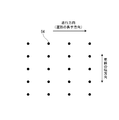
- a marker laying location where there is a possibility of laying a magnetic marker is set one-dimensionally or two-dimensionally on the traveling path, and a plurality of laying modes including a mode in which the magnetic marker is not laid at each marker laying location. It is preferable that any one of them is selected and the code information can be provided to the vehicle side by combining magnetic marker laying modes at a plurality of marker laying locations. In this case, the code information can be provided by a combination of magnetic marker laying modes at a plurality of marker laying locations.
- the laying mode of the magnetic marker may include a mode of laying the magnetic marker so that the N pole is located on the surface side and a mode of laying the magnetic marker so that the S pole is located on the surface side.
- three modes of N pole, S pole, and no laying can be set as the laying mode, and three values can be expressed by one marker laying point.
- binary values are expressed by the N pole and the S pole, the number of the magnetic markers required to provide the same amount of information can be reduced.
- the vehicle includes an installation location specifying unit that specifies a plurality of marker installation locations, an information acquisition unit that detects the installation mode of the magnetic marker for the plurality of marker installation locations, and acquires the code information; It is good to have. If it is possible to specify the marker laying location on the vehicle side, it is possible to detect with high certainty an aspect in which the magnetic marker is not laid.
- the code information may be information represented by a distance between two magnetic markers arranged in the vehicle width direction or the longitudinal direction of the travel path.
- the code information may be expressed by increasing or decreasing the distance between two magnetic markers for a magnetic marker arranged one-dimensionally in the longitudinal direction.
- information can be represented by a combination of increased distance, decreased distance, unchanged distance, and the like.
- Information can also be expressed by the difference itself when the distance increases or decreases, or by a combination of sizes.
- the two magnetic markers having the above-mentioned distance may be two magnetic markers adjacent in the arranged direction, and may be a predetermined number in the arranged direction, such as every other, every second, every third, etc. Two magnetic markers may be positioned with another magnetic marker interposed therebetween.
- the code information may be information represented by a magnetic intensity at which each magnetic marker acts on the vehicle side.
- information can be expressed by combinations of adjacent magnetic markers such as increased magnetic intensity, decreased magnetic intensity, and unchanged magnetic intensity. Further, for example, information can be expressed by the magnetic intensity itself on which the magnetic marker acts.
- the code information may be information represented by the arrangement of the magnetic markers.
- the arrangement includes the number of magnetic markers laid out in addition to the arrangement shape formed by a plurality of the magnetic markers.
- Examples of the arrangement shape include a shape in which a plurality of the magnetic markers are arranged in one horizontal row, one vertical row, two horizontal rows, two vertical rows, a triangle, a rhombus, and the like. Further, for example, while providing marker laying locations one-dimensionally along the longitudinal direction of the travel path, the number of magnetic markers laid side by side at each marker laying location is changed, and information can be expressed by a combination of these numbers. good.
- the vehicle includes a positioning unit that measures an absolute position, and a support information presentation unit that presents driving support information using the absolute position where the vehicle is located to the driver side,
- the information returned from the base station to the vehicle may include position information that can specify an absolute position where the vehicle is located.
- the absolute position can be specified by the information received from the base station. Accordingly, it is possible to realize a robust system capable of providing the driving support information to the driver with high accuracy regardless of whether or not the positioning by the positioning unit is possible.
- said positioning part there exist some which utilize GPS, for example. In the case of GPS, the above configuration is effective because positioning frequently becomes impossible or accuracy becomes insufficient depending on the reception status of satellite radio waves.
- the use of the information returned from the base station may be driving assistance by presenting the information itself or processed information to the driver, or driving assistance by vehicle control using the information.
- a mode of presenting information or the like to the driver there is a mode of presenting using a display display, a speaker, an alarm, a buzzer, a vibrator, or the like, for example.
- vehicle control include control for realizing automatic braking, control for realizing automatic steering, control for automatically controlling an engine throttle, and the like.
- Example 1 This example is an example related to a driving support system 1A using the magnetic marker 1. The contents will be described with reference to FIGS.
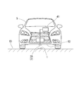
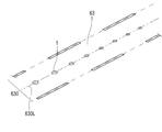
- the vehicle driving support system 1 ⁇ / b> A includes a road-vehicle communication unit in addition to an in-vehicle unit 2 ⁇ / b> A including a magnetic marker 1 laid on a road surface 63 of a traveling path of a vehicle 5, a magnetic sensor 2, and the like.
- the system is a combination of a vehicle 5 having 41 and a base station 6 capable of communicating with the vehicle 5 side by road-to-vehicle communication.
- wireless communication between the vehicle 5 side and the base station 6 is possible via the communication unit 60 installed on the road side.
- the communication unit 60 is communicably connected to the base station 6 via a dedicated communication line or an Internet line.
- the output signal of the in-vehicle unit 2A (FIG. 2) attached to the vehicle body floor 50 that hits the bottom surface of the vehicle 5 is input to, for example, an ECU (not shown) on the vehicle 5 side.
- Information such as the detection of the magnetic marker 1 and the amount of lateral deviation that is a deviation in the vehicle width direction with respect to the magnetic marker 1 includes automatic steering control for lane keeping, lane departure warning, route navigation, traffic information display, It can be used for various driving support such as warning and automatic driving.
- the vehicle 5 constituting the driving support system 1 ⁇ / b> A of this example can acquire code information from the magnetic marker 1.
- the vehicle 5 can acquire two-dimensional position information as information corresponding to the code information by transmitting the code information to the base station 6. If two-dimensional position information that can be acquired from the base station 6 is used, for example, a navigation system or the like can be configured.
- a navigation system or the like can be configured.
- the configuration of the driving support system 1A of this example will be described.
- the base station 6 is a server device connected to a dedicated line or an internet line.
- the base station 6 as a server device includes a database that stores a large amount of position information with code information attached.
- the base station 6 receives the code information from the vehicle 5 side as described above, the base station 6 reads out the position information to which the code information is attached and sends it back to the transmission source vehicle 5.
- the communication unit 60 installed on the roadside may have the database function of the base station 6 distributed.
- the database to be distributed to the communication units 60 may be a small database corresponding to code information that may be acquired by the traveling vehicle 5 within a range in which the communication units 60 can perform wireless communication.
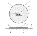
- the magnetic marker 1 has a flat circular shape with a diameter of 100 mm and a maximum thickness of about 2.0 mm, and is a marker that can be adhesively bonded to the road surface 63.
- a sheet-like RFID tag (Radio Frequency IDentification, wireless tag) 15 is laminated on the surface side.
- the magnetic marker 1 of this example including the RFID tag 15 can provide code information to the vehicle 5 side without depending on a magnetic method.
- the magnetic marker 1 is a marker in which the front and back sides of a flat magnet sheet 11 having a diameter of 100 mm and a thickness of 1 mm are covered with a resin mold 12.
- the magnet sheet 11 which is an example of a magnetism generating unit is an isotropic ferrite rubber magnet sheet having a maximum energy product (BHmax) of 6.4 kJ / m 3 .
- the magnet sheet 11 is a bonded magnet formed into a sheet shape by mixing a raw material, which is a magnetic powder of iron oxide, with rubber as a binder.
- the sheet-like RFID tag 15 having a thickness of 0.5 mm is laminated on the surface of the magnet sheet 11.
- the resin mold 12 on the front surface side covers the front surface side of the magnet sheet 11 on which the RFID tags 15 are stacked.
- the thickness of the resin mold 12 on the front surface side of the magnetic marker 1 is 0.3 mm, and the thickness on the back surface side corresponding to the construction surface of the magnetic marker 1 is 0.2 mm.
- the portion where the RFID tag 15 is disposed has a maximum thickness, and the maximum thickness including the thickness of the resin mold 12 is 2.0 mm.
- a sheet having a diameter of 100 mm and a thickness of 0.5 to 1.0 mm provided with a rectangular arrangement hole corresponding to the RFID tag 15 is laminated on the surface of the magnet sheet 11, and the RFID tag 15 is positioned in the arrangement hole. It is also good. In this case, the thickness of the portion where the RFID tag 15 is disposed can be equal to or thinner than other portions. Thereby, when the magnetic marker 1 is stepped on the tire etc. of the vehicle 5, the load which acts on the RFID tag 15 can be suppressed.
- the construction of the magnetic marker 1 on the road surface 63 is performed by, for example, bonding and fixing with an adhesive.
- a resin mold may be applied to the outer peripheral side surface of the magnetic marker 1.
- it is also possible to form a resin mold reinforced with glass fibers by laminating a glass cloth or the like on the surface of the magnet sheet 11 on which the RFID tag 15 is laminated, and impregnating the glass cloth with a resin.
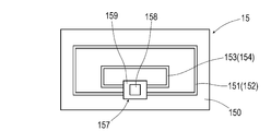
- the RFID tag 15 that is an example of an information providing unit is an electronic component in which an IC chip 157 is mounted on the surface of a tag sheet 150 that is a sheet-like member, as shown in FIGS.
- the RFID tag 15 operates with electric power supplied from outside by wireless transmission, and is configured to wirelessly transmit code information stored in the IC chip 157.
- the RFID tag 15 of this example is a wireless tag using the 900 MHz band.
- the RFID tag 15 can be easily downsized, and robust radio communication can be realized because of high radio wave permeability.
- seat 11 which is a bond magnet is equipped with the characteristic that there are few high frequency losses. Therefore, the magnet sheet 11 has a low degree of attenuation of the 900 MHz band radio wave transmitted by the RFID tag 15 and has a high affinity with the RFID tag 15.
- the tag sheet 150 is a sheet-like member cut out from the PET film.
- a loop coil pattern 151 and an antenna pattern 153 which are printed patterns of conductive ink such as silver paste, are formed.
- Each of the loop coil pattern 151 and the antenna pattern 153 has a substantially annular shape having a notch at one place.
- a chip placement area (not shown) for placing the IC chip 157 is formed in the notched portion.
- the loop coil pattern 151 is a pattern that forms the power receiving coil 152.
- An exciting current is generated in the loop coil pattern 151 by electromagnetic induction from the outside.
- the antenna pattern 153 is a pattern that forms the transmission antenna 154 that wirelessly transmits information.
- the power receiving coil 152 formed by the loop coil pattern 151 and the transmission antenna 154 formed by the antenna pattern 153 both have sensitivity in the vertical direction of the formation surface. This sensitivity specification is suitable for communication with the in-vehicle unit 2 ⁇ / b> A attached to the vehicle body floor 50 of the vehicle 5.
- As the conductive ink for printing the patterns 151 and 153 graphite paste, silver chloride paste, copper paste, nickel paste, etc. can be used in addition to silver paste. Further, the patterns 151 and 153 can be formed by copper etching or the like.
- the IC chip 157 is an electronic component in which a semiconductor element 158 including a ROM and a RAM as memory means is mounted on the surface of a sheet-like base material 159.
- the RFID tag 15 is produced by attaching the IC chip 157 to the surface of the tag sheet 150 described above.
- various bonding methods such as ultrasonic bonding and caulking bonding can be employed in addition to the conductive adhesive.
- the electrical configuration of the RFID tag 15 will be described later with reference to the block diagram of FIG.
- the tag sheet 150 of the RFID tag 15 and the substrate 159 of the IC chip 157 a resin film such as polyethylene (PE), polyethylene terephthalate (PET), polypropylene (PP), paper, or the like can be used.
- the IC chip 157 may be a semiconductor element itself or a chip obtained by packaging a semiconductor element with a plastic resin or the like.
- Table 1 shows part of the shape specifications and magnetic specifications of the magnet sheet 11 provided in the magnetic marker 1 of this example.
- the magnetic field distribution in which the magnetic marker 1 acts in the vertical direction is as shown in FIG.
- the figure is a semilogarithmic graph showing a simulation result by an axisymmetric three-dimensional static magnetic field analysis using a finite element method.
- a simulation program in which the accuracy of the simulation has been confirmed in advance by a demonstration experiment is used. Furthermore, for some of the data shown in the figure, it has been confirmed by simulation that the simulation values are correct.
- the logarithmic scale of magnetic flux density acting in the vertical direction is set on the vertical axis, and the vertical height (height from the marker surface) with respect to the surface of the magnetic marker 1 is set on the horizontal axis. is doing.
- Gs surface magnetic flux density
- a magnetic flux density of 8 microtesla or more is ensured in a range of 100 to 250 mm assumed as a mounting height of the magnetic sensor 2.
- the vehicle 5 includes a road-to-vehicle communication unit 41 that performs communication with the base station 6 and an in-vehicle unit 2A that performs detection of the magnetic marker 1 and the like (see FIG. 2).
- the road-vehicle communication unit 41 is a communication unit that performs communication with the base station 6 via a communication unit 60 (see FIG. 1) installed on the road side.
- the in-vehicle unit 2A includes the magnetic sensor 2 in FIG. 6 that magnetically detects the magnetic marker 1 and the tag reader 3 in FIG. 7 that acquires information from the magnetic marker 1.
- the in-vehicle unit 2 ⁇ / b> A is attached to a vehicle body floor 50 that forms the bottom surface of the vehicle 5 so that the magnetic marker 1 laid on the road surface 63 can be detected.
- the mounting height of the in-vehicle unit 2A is in the range of 100 to 250 mm, although it varies depending on the vehicle type.
- the magnetic sensor 2 and the tag reader 3 constituting the in-vehicle unit 2A will be described in order.
- the magnetic sensor 2 that is an example of a magnetic detection unit is a one-chip MI (Magnet Impedance) sensor in which an MI element 21 and a drive circuit are integrated.
- the MI element 21 is an element including an amorphous wire (an example of a magnetic sensitive body) 211 made of a CoFeSiB alloy having substantially zero magnetostriction and a pickup coil 213 wound around the amorphous wire 211.
- the magnetic sensor 2 detects magnetism acting on the amorphous wire 211 that is a magnetosensitive body by measuring an induced voltage of the pickup coil 213 when a pulse current is applied to the amorphous wire 211.
- the MI element 21 has detection sensitivity in the axial direction of the amorphous wire 211 that is a magnetic sensitive body. In the vehicle 5, the magnetic sensor 2 is installed so that the amorphous wire 211 is along the traveling direction.
- the drive circuit includes a pulse circuit 23 that supplies a pulse current to the amorphous wire 211, and a signal processing circuit 25 that samples and outputs the induced voltage of the pickup coil 213 at a predetermined timing.
- the pulse circuit 23 is a circuit including a pulse generator 231 that generates a pulse signal that is a source of a pulse current.
- the signal processing circuit 25 is a circuit that takes out an induced voltage of the pickup coil 213 through a synchronous detection 251 that is opened and closed in conjunction with a pulse signal, and amplifies it with a predetermined amplification factor by an amplifier 253.
- the signal amplified by the signal processing circuit 25 is output to the outside as a sensor signal.
- the magnetic sensor 2 is a highly sensitive sensor having a magnetic flux density measurement range of ⁇ 0.6 millitesla and a magnetic flux resolution within the measurement range of 0.02 microtesla. Such high sensitivity is realized by the MI element 21 utilizing the MI effect that the impedance of the amorphous wire 211 changes sensitively according to the external magnetic field. According to the magnetic sensor 2 having a magnetic flux resolution of 0.02 micro tesla (see Table 2), a magnetic flux density of at least 8 micro tesla (see FIG. 5) is applied in the mounting height range of 100 to 250 mm. The magnetic marker 1 to be detected can be detected with high certainty. Furthermore, the magnetic sensor 2 can perform high-speed sampling at a cycle of 3 kHz, and is compatible with high-speed driving of the vehicle.
- the tag reader 3 that is an example of the information acquisition unit includes a power supply unit 31 that supplies power to the RFID tag 15 included in the magnetic marker 1, and information that acquires code information wirelessly transmitted by the RFID tag 15. And an acquisition unit 33.
- the power supply unit 31 is an electronic circuit that supplies current to the loop coil 310 to generate a magnetic field and transmits power by electromagnetic induction.
- the information acquisition unit 33 is an electronic circuit that receives a radio wave transmitted by the RFID tag 15 using the loop antenna 330 and extracts code information by demodulation.
- the tag reader 3 transmits electric power by generating an exciting current in the power receiving coil 152 on the RFID tag 15 side by electromagnetic induction by the magnetic field generated by the loop coil 310, and stores the power in the power receiving unit 155 on the RFID tag 15 side.
- the wireless transmission unit 156 operates upon receiving power supply from the power reception unit 155, and transmits code information and the like to the vehicle 5 side via the transmission antenna 154.
- the work vehicle is a dedicated work vehicle equipped with a reader / writer having a data writing function, new code information can be written into the RAM, data can be rewritten, and the like.
- the detection process of the magnetic marker 1 is repeatedly executed using the magnetic sensor 2 of the in-vehicle unit 2A (S101).
- the in-vehicle unit 2A causes the tag reader 3 to perform power transmission, thereby supplying operating power to the RFID tag 15 of the magnetic marker 1 (S103).
- the in-vehicle unit 2A causes the tag reader 3 to start reception / demodulation processing in synchronization with the wireless transmission started in response to the operation of the RFID tag 15 (S104), and acquires code information transmitted by the RFID tag 15.
- the road-vehicle communication unit 41 transmits the code information to the base station 6 through wireless communication with the communication unit 60 (FIG. 1) installed on the roadside ( S202).
- the road-to-vehicle communication unit 41 waits until it receives a reply of the position information corresponding to the code information from the base station 6 (S203), and ends the communication process in response to the reception of the position information (S203: YES). Thereafter, the in-vehicle unit 2A waits for acquisition of new code information (S201: NO).
- the position information corresponding to the code information is read with reference to the database (S302). Then, the read position information is returned to the vehicle 5 that is the transmission source of the code information (S303).
- an identification ID is assigned to each vehicle 5, and the identification ID is attached to code information received by the base station 6.
- the transmission source vehicle 5 can be specified by the identification ID attached to the received code information, and the position information can be returned to the vehicle 5 with high reliability.
- two-dimensional position information can be acquired on the vehicle 5 side without using, for example, GPS (Global Positioning System), and a navigation system can be realized. Further, when the vehicle 5 is located in the middle of the adjacent magnetic markers 1 in the traveling direction of the vehicle 5, the vehicle position is estimated by inertial navigation using measured values such as the vehicle speed and the yaw rate, and every time the vehicle passes the magnetic marker 1. It is good to get the exact position.
- GPS Global Positioning System
- a navigation system having a positioning unit that measures an absolute position using satellite radio waves received from GPS satellites, and a support information presentation unit that presents driving support information to the driver using the measured absolute position.
- the combination with is also effective. It is preferable to lay a magnetic marker 1 capable of providing position information at a location where GPS satellite radio waves cannot be received or are likely to be unstable, such as a tunnel or a valley of a building. If position information that can specify the absolute position of the vehicle 5 can be returned from the base station 6, a poor reception state of GPS radio waves can be backed up, and the position capturing accuracy by the navigation system can be improved.
- Detailed position information Information such as road gradient, curvature of the road ahead, type of lane in which the vehicle is traveling, legal speed, etc. may be included in the position information. If there is such detailed information, for example, driving support that alerts the driver, or vehicle control such that the engine brake is effective with the gear set as one stage before a steep downhill or a sharp curve Is possible.
- the magnetic marker 1 may be laid in a passage such as a self-propelled multilevel parking lot such as a shopping center, and height information such as the number of floors may be provided to the vehicle 5 side.
- height information such as the number of floors
- GPS or the like it is not easy to specify the number of floors in a building. If the number of floors where the vehicle is located is unknown, it is difficult to provide route guidance to the vacant frames with high accuracy even if vacant frame information with designated floor numbers is provided from the infrastructure side. If there is provision of height information that can specify the number of floors, highly accurate route guidance to empty frames in a self-propelled multilevel parking lot can be realized.
- Traffic information such as information on intersections, information on branches, and information on junctions
- the magnetic marker 1 may be installed at a characteristic point on a road (traveling road) such as an intersection, a branch road, or a combined flow path, and traffic information regarding the road shape may be provided from the base station 6.
- driving assistance using traffic information there are various driving assistance controls such as a display for alerting the driver, presentation of traffic information by an alarm sound, etc., and brake control and steering control. For example, if the distance between the stop line at the intersection and the magnetic marker 1 is defined, the brake control for stopping at the stop line can be executed with high accuracy.
- the driving support control for branching on the branch path can be executed with high accuracy.
- Information on the distance between the intersection or the branch path and the magnetic marker 1 may be included in the information provided from the base station 6.
- the base station 6 can collect real-time information such as accidents, incidents and regulations, the real-time information can be provided to the vehicle 5 side as traffic information.
- the base station 6 side can grasp
- the magnetic marker 1 constituting the driving support system 1A of this example includes the RFID tag 15 as an information providing unit.
- the presence / absence of the magnetic marker 1 and the lateral displacement amount of the vehicle 5 in the vehicle width direction can be detected, and the code information acquired from the magnetic marker 1 is used.
- Information useful for driving support can be acquired from the base station 6. If it is the driving assistance system 1A which lays the high-functional magnetic marker 1 provided with the RFID tag 15 on the traveling road, various driving assistances can be realized by using the magnetic marker 1.
- the magnetic flux density Gs on the surface is suppressed to 1 millitesla while ensuring the magnetic characteristics detectable by the magnetic sensor 2.
- the magnetic flux density of 1 millitesla is even smaller than, for example, 1/10 of the magnetic flux density of about 20 to 40 millitesla on the surface of a magnet sheet attached to a whiteboard, a refrigerator door, or the like.
- the magnetic marker 1 has a very weak magnetic force even compared to these office or household magnet sheets.
- the magnetic field generated by the magnetic marker 1 is extremely weak, the efficiency of electromagnetic induction when transmitting power from the vehicle 5 side can be increased, and the reliability and efficiency of power transmission can be ensured.
- the RFID tag 15 and the tag reader 3 employ loop-shaped magnetic field antennas that detect magnetic field components and the like as the antennas 154 and 330 for transmitting and receiving information. If the peripheral magnetic field is large, information transmission / reception may be affected. However, if the magnetic field generated by the magnetic marker 1 is weak, the reliability of wireless communication is less likely to be impaired.
- an isotropic ferrite rubber magnet which is a bonded magnet formed by mixing rubber as a binder with magnetic powder of iron oxide, is illustrated as the magnet sheet 11 forming the magnetism generating portion of the magnetic marker 1.
- the magnet of the magnetic marker may be a bonded magnet such as a plastic magnet molded with a mold after the raw material, which is magnetic powder of iron oxide, is mixed with the raw material, plastic, and then melted, and the raw material is baked and hardened.
- a sintered magnet or the like may be used.
- the ferrite magnet forming the magnet sheet 11 has a characteristic that electric resistance is large. Therefore, when electric power is transmitted by electromagnetic induction, there is little possibility that an eddy current is generated on the surface of the magnet sheet 11, and transmission efficiency when electric power is transmitted wirelessly can be ensured. Further, in the magnet sheet 11 which is a bonded magnet obtained by pulverizing a magnet and kneaded into a rubber which is a binder, the pulverized magnets are bonded by a binder which is an insulator, and the electric resistance is very large. Therefore, with this magnet sheet 11, there is almost no possibility of causing high-frequency loss when the RFID tag 15 performs wireless communication.
- the RFID tag 15 is disposed so as to be attached to the front surface, back surface, or side surface of the magnet sheet 11 or the magnetic marker 1, the RFID tag 15 is disposed inside the magnet sheet 11 or the magnetic marker 1, or the magnetic marker.
- an RFID tag 15 may be disposed on the lower side of 1.
- a high frequency of 100 kHz or higher can be selected as the carrier frequency for wireless communication by the RFID tag 15. If the carrier frequency is high, the RFID tag can be easily downsized. In particular, in the case of a carrier frequency in the 900 MHz band, for example, since the transparency is high, it is relatively easy to ensure communication stability and the robustness can be improved.
- a bonded magnet with low high-frequency loss such as a rubber magnet or plastic magnet
- a carrier frequency in the 900 MHz band wireless communication robustness and RFID tag size reduction And both.
- a similar effect can be expected if the RFID tag uses a frequency band of 710 to 960 MHz.
- the sensor using the MI element 21 is illustrated as the magnetic sensor 2, a fluxgate sensor or a TMR type sensor may be used as the magnetic sensor instead.
- a combination of two or more of an MI sensor, a fluxgate sensor, and a TMR sensor can be employed.
- the position of the magnetic sensor installed in the vehicle is at least about 100 mm away from the road surface.
- the magnetic material and the kind of magnet of the magnet sheet 11 constituting the magnetic marker 1 are not limited to this example. Various types and types of magnetic materials and magnets can be used. It is preferable to selectively determine an appropriate magnetic material and type according to the magnetic specifications and environmental specifications required for the magnetic marker 1. Note that the RFID tag 15 and the tag reader 3 may share an antenna for power transmission and an antenna for transmitting or receiving information.
- the RFID tag 15 is provided on the front side of the magnetic marker 1, but the RFID tag 15 may be provided on the back side.
- the RFID tag 15 is positioned on the back side of the magnetic marker 1 body. For example, even when the magnetic marker 1 is stepped on a vehicle tire, since the RFID tag 15 can be protected by the main body of the magnetic marker 1, the configuration for protecting the RFID tag 15 can be simplified.
- RFID tags may be stacked on the surface of the magnetic marker 1 after the resin mold layer is formed. The same applies to the case where an RFID tag is disposed on the back side or side surface of the magnetic marker 1.
- an inter-vehicle communication device that enables mutual communication between the vehicles 5 may be provided in each vehicle 5.
- the vehicles 5 on the road can transmit and receive each other's position information wirelessly. If each vehicle 5 can grasp the positional relationship with other vehicles in the vicinity, the safety and accuracy of vehicle control for driving assistance including automatic driving can be improved.
- the position information based on the position information received from the base station 6 may be used as the position information of the own vehicle position exchanged between the vehicles.
- the position information including the movement information by inertial navigation after passing through the magnetic marker 1 is set as position information obtained by correcting the lateral displacement amount of the own vehicle with respect to the magnetic marker 1 in the vehicle width direction. It is good to set as a position.
- a sheet-shaped magnetic marker 1 is illustrated as a magnetic marker.
- the shape of the magnetic marker may be a columnar shape such as a circular cross section or a polygonal cross section.
- the combination of the columnar magnetic marker height and outer diameter may be a long and narrow columnar shape whose height dimension is larger than the outer diameter, but it is a short columnar shape whose outer diameter dimension is larger than the height.
- a cylindrical shape having a height of 10 to 20 mm and a diameter of 25 to 30 mm is preferable.
- a ferrite plastic magnet which is a kind of bonded magnet, may be adopted.
- accommodation spaces such as depressions or holes for accommodating the magnetic markers in the road.
- accommodation space it is preferable to secure a large dimension in the depth direction with respect to the height of the magnetic marker.
- the upper end surface of the magnetic marker disposed in the accommodation space is lower than the road surface.
- the magnetic marker may be sealed by filling with a methacrylic resin filler to improve uniformity with the surrounding road surface.
- asphalt may be adopted as the filler.
- a woven or non-woven fabric such as glass fiber, carbon fiber, or cellulose nanofiber may be disposed on the upper end surface side of the magnetic marker.
- the characteristics of the filler can be enhanced by impregnating the woven or non-woven fabric with the filler.
- the size of the woven or non-woven fabric may be smaller than the cross-sectional shape of the storage space, but may be slightly larger than the cross-sectional shape of the storage space. If it is a woven cloth etc. larger than the cross-sectional shape of a storage space, a magnetic marker can be integrally covered with the road surface around a storage space. In this case, the opening portion of the accommodation space can be protected integrally with the surrounding road surface. For example, the dent of the opening part of an accommodation space can be suppressed, and the favorable laying state of a magnetic marker can be maintained long in the operation over a long period of time on a road.
- Example 2 In this example, instead of the magnetic marker of the first embodiment, a magnetic marker 1 in which an image pattern is formed on the surface side is employed.
- the contents will be described with reference to FIGS.
- the magnetic marker 1 in FIG. 9 has the same shape and magnetic specifications as those of the first embodiment, and the surface treatment such as resin molding is the same.
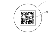
- the difference is that the RFID tag 15 is not laminated on the surface side, and instead, a code image 18 which is an image-like pattern that is an example of an information providing unit is formed by printing or the like.
- the in-vehicle unit constituting the driving support system of the present example performs code processing from the code image 18 by performing image processing on the camera that images the road surface 63 and the captured image of the magnetic marker 1 instead of the tag reader of the first embodiment.
- a combination (not shown) with the image ECU that reads the image ECU is provided as an example of the information acquisition unit.
- a film on which a code image 18 such as a barcode or a QR code (registered trademark) is printed is laminated on the surface of the magnet sheet 11, and a transparent resin mold layer is further formed on the surface.
- the camera on the vehicle 5 side is attached with the lens facing downward so that the surface of the magnetic marker 1 laid on the road surface 63 can be imaged.
- the image ECU is configured to capture a captured image of the camera and perform image processing when the magnetic marker 1 can be detected magnetically, to cut out a code image area and to read code information represented by the code image 18 Has been.
- a code image may be printed directly on the surface of the resin mold that covers the surface side of the magnet sheet 11.
- a transparent protective layer may be provided on the surface side of the code image.
- a code image in which a white portion is convex and a black portion is uneven such as a recess may be formed.
- a black sheet in the code image is covered with a white sheet provided with a hole so that the black color of the magnet sheet 11 can be seen from the outside through the hole, and the code image is displayed in comparison with the white part of the white sheet. It is also good to do.
- a color pattern may be displayed instead of the code image.
- the color pattern include a pattern of a single color, a color coating pattern, and the like. In the case of a single color, it is conceivable to display a safe part in blue, an accident-prone and dangerous part in red, an intersection in red, a combined path in yellow, and a branch path in blue.
- the color painting pattern for example, the code information may be represented by a color painting pattern 19 of four regions divided by angles as shown in FIG. Further, if the amount of information that can be provided by one magnetic marker 1 is not sufficient for the purpose, a combination of two or more magnetic patterns 1 such as two adjacent in the traveling direction of the vehicle 5 is combined. One code information can also be expressed. Other configurations and operational effects are the same as those in the first embodiment.
- Example 3 This example is an example in which the configuration for providing code information to the vehicle side is changed based on the driving support system of the first embodiment.
- Information provided to the vehicle side by the base station in response to reception of the code information is two-dimensional position information similar to that in the first embodiment. The contents will be described with reference to FIGS.
- a plurality of magnetic markers 1 are laid in a one-dimensional manner along the center 630L of the lane 630 forming the travel path of the vehicle 5.
- the magnetic marker 1 of this example is based on the magnetic marker of Example 1, omitting the RFID tag, and setting the thickness of the resin molds on both the front and back sides forming the S and N poles to 0.3 mm. It can be installed without distinction.
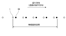
- the driving support system 1A is characterized in that an information providing section for providing code information to the vehicle 5 side using the magnetic marker 1 is set as shown in FIGS.
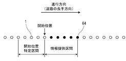
- marker laying locations 64 where there is a possibility of laying the magnetic marker 1 are set along the lane 630 every prescribed distance (for example, 2 m).
- the magnetic marker 1 is laid as the magnetic marker 1 in addition to the mode 1N in which the N pole is laid on the upper surface and the mode 1S in which the S pole is laid on the upper surface.
- the mode 1E which is not set is set.
- the combination of the laying mode of the magnetic marker 1 in the plurality of marker laying locations 64 represents the code information, and the code information can be acquired on the vehicle 5 side by reading the combination of the laying mode.
- a start position specifying section in which five N-pole magnetic markers 1 are continuously laid along the longitudinal direction (traveling direction) of the lane 630 is formed. Also in this start position specifying section, the interval between the adjacent magnetic markers 1 is the specified distance.
- the magnetic marker 1 in the non-information providing section that is neither the information providing section nor the start position specifying section is preferably the S pole. If the magnetic marker 1 in the non-information providing section is the S pole, it is easy to specify the start position specifying section in which the N pole magnetic markers 1 are arranged.
- a system on the vehicle 5 side is formed centering on the in-vehicle unit 45 and the road-to-vehicle communication unit 41 that execute various arithmetic processes and display processes.
- the system on the vehicle 5 side has the following functions.
- Installation location specifying unit specifies the position of the marker installation location 64 where the magnetic marker 1 may be installed.
- Magnetic detection unit Detects the magnetic marker 1 at a location identified as the marker laying location 64.
- Information acquisition unit Reads code information based on a combination of detection results of a plurality of magnetic markers 1, and acquires corresponding position information from the base station.
- Support unit Supports driving using the magnetic marker 1.
- Laying location specifying section is laid for specifying the position of a vehicle speed sensor 459 that generates a pulse signal every time the tire of the vehicle 5 makes one rotation and the marker laying location 64 as shown in FIG. It is configured to include an installation database 451 storing data and an in-vehicle unit 45 that identifies the marker installation location 64.
- the laying data includes a code indicating the start position of the information providing section (combination of the laying mode of the magnetic marker 1 in the above-described start position specifying section), distance data indicating a specified distance that is an interval between the marker laying points 64, and the like. It is.
- the magnetic detection unit includes the magnetic sensor 2.
- the magnetic sensor 2 has the same specifications as in the first embodiment, and the mounting specifications for the vehicle are also the same.
- the magnetic sensor 2 of this example tries to detect the magnetic marker 1 every time the vehicle 5 reaches the marker laying location 64, and determines the polarity of the magnetic marker 1 when it can be detected. .
- a method for determining the polarity by the magnetic sensor 2 will be described later.
- the information acquisition unit includes an in-vehicle unit 45 (FIG. 14) that reads code information from the magnetic marker 1 side, and a road-to-vehicle communication unit 41 that transmits code information to the base station and receives a corresponding position information reply. (FIG. 14).
- the in-vehicle unit 45 is a unit that reads code information representing a combination of the magnetic marker 1 installation modes (presence / absence and polarity of the magnetic marker 1) at each marker installation location 64 in the information providing section (see FIG. 12).
- the code information represented by the laying mode of the magnetic marker 1 a 5-digit code is adopted in both the information providing section and the start position specifying section.
- the position information returned by the base station is information indicating the absolute position of the last marker laying place among the five marker laying places 64 constituting the information providing section.
- the support unit of this example executes a navigation system that is an example of a driving support system, as in the first embodiment that uses position information provided from a base station.
- the magnetic sensor 2 As described in the first embodiment, in the magnetic sensor 2, the amorphous wire, which is a magnetic sensitive body, is disposed along the traveling direction. Therefore, for example, as shown in FIG. 15, the magnetic sensor 2 outputs a positive sensor signal when it is positioned in front of the N-pole magnetic marker 1, and has a negative value when it passes through the N-pole magnetic marker 1. Output sensor signal.
- the magnetic sensor 2 outputs a negative sensor signal when positioned before the S-pole magnetic marker 1 and outputs a positive sensor signal when it passes through the S-pole magnetic marker 1.
- the polarity of the magnetic marker 1 can be determined by determining whether the value of the sensor signal before and after passing through the magnetic marker 1 is positive or negative, determining whether the differential value of the sensor signal (change slope of the sensor signal) is positive, or the like.
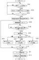
- the in-vehicle unit 45 When the vehicle 5 is traveling on the road in which the information provision section (see FIG. 12) is set, the in-vehicle unit 45 repeatedly executes detection of the magnetic marker 1 until the start position of the information provision section is specified. (S101). When the in-vehicle unit 45 detects the magnetic marker 1 (S101: YES), the in-vehicle unit 45 forwards each digit of the 5-digit code for storing the combination of the laying modes of the magnetic marker 1 to the upper order and sets the least significant bit to an empty bit. The values of the detected magnetic marker 1 are sequentially set (S102). In the driving support system 1A, the laying mode in which the N pole is detected is treated as a value of 1, the laying mode in which the S pole is detected is a value of 2, and the laying mode without a magnetic marker is treated as a zero value.
- the vehicle 5 enters the start position specifying section (see FIG. 12) in which five N-pole magnetic markers 1 are continuously installed, and detects the fifth N-pole magnetic marker 1.
- the in-vehicle unit 45 specifies the start position of the information providing section. Specifically, the in-vehicle unit 45 specifies the laying position of the fifth N-pole magnetic marker 1 in the longitudinal direction (traveling direction) of the lane 630 as the start position of the information providing section (see FIG. 12) ( S104), the moving distance of the vehicle 5 is reset to zero (S105).
- the in-vehicle unit 45 calculates the movement distance from the number of pulse signals output from the vehicle speed sensor 459 every time the tire rotates once.
- the in-vehicle unit 45 executes the detection process of the magnetic marker 1 every time the moving distance reaches a specified distance that is an interval between the marker laying locations 64 in the information providing section (S106: YES) (S107).
- the presence / absence and polarity of the magnetic marker 1 are determined with reference to the change in the sensor signal of the magnetic sensor 2 within the temporal range including the moment when the marker laying point 64 is reached.
- each digit of the 5-digit code is forwarded to the upper order, the lowest order is made an empty bit, and a bit value representing a new detection result is added.
- S108: N pole a bit value 1 is added (S119)
- S108: S pole the bit value 2 is added (S129)
- S108: none a bit value 0 is added (S139).
- the in-vehicle unit 45 passes through the five marker laying locations 64 in the information providing section and generates a five-digit code (S110: NO), and the processing after step S105 is performed each time the marker laying location 64 is reached. Repeatedly. Thereafter, when the vehicle-mounted unit 45 generates code information consisting of a 5-digit code after passing through the five marker laying locations 64 in the information providing section (S110: YES), the road-to-vehicle communication unit 41 transmits the code information to the base station. (S111). Thereby, the information corresponding to this code information can be received from the base station via the road-vehicle communication unit 41 (S112).
- code information can be provided to the vehicle 5 side by combining the laying aspect of the magnetic marker 1 in the information providing section.
- the mode 1E in which the magnetic marker 1 is not laid can be set as the laying mode.
- code information can be efficiently provided by using a small number of magnetic markers 1.
- the magnetic marker 1 in the information providing section is also used for a lane departure warning or the like, the maximum interval between adjacent magnetic markers 1 in the information providing section is equal to the laying interval of the magnetic marker 1 in the non-information providing section. It is preferable to configure the following.
- the specified distance which is the interval between the marker laying locations 64 in the information providing section, is 1 ⁇ 2 of the laying interval necessary for the lane departure warning, etc., and the configuration in which the magnetic marker 1 is not laid is not continued at two locations. Good.
- the maximum interval of the magnetic markers 1 in the information providing section can be made equal to the laying interval necessary for the lane departure warning or the like.
- a marker laying point 64 is set adjacent to the downstream side in the traveling direction (longitudinal direction of the road) with respect to the magnetic marker 1 for the purpose of lane departure warning or the like. It is also good.
- the position of the marker laying location 64 can be specified by detecting the magnetic marker 1 for a lane departure warning or the like.
- the magnetic sensor that detects the magnetic marker 1 functions as an installation location specifying unit that specifies the marker installation location 64 in position. Note that a marker laying location 64 may be provided adjacent to the magnetic marker 1 for a lane departure warning or the like in the vehicle width direction.
- the number of marker laying points 64 in the information provision section (FIG. 12), the prescribed distance forming the interval, and the like are not limited to the values in this example, and can be changed as appropriate.
- the number of marker laying points 64 in the information providing section and the number of laying of the magnetic markers 1 in the start position specifying section are both five, but each number can be changed as appropriate, and different numbers are used. May be set.
- the marker laying locations are arranged one-dimensionally along the longitudinal direction of the lane 630, but the marker laying locations 64 may be arranged one-dimensionally in the width direction of the lane as shown in FIG. .
- a sensor unit 2U in which a plurality of magnetic sensors 2 are arranged in the vehicle width direction may be attached to the vehicle 5.
- the marker laying locations 64 may be two-dimensionally arranged as shown in FIG. In this case, more information can be provided at a short distance.
- Other configurations and operational effects are the same as those in the first or second embodiment.
- Example 4 This example is an example in which the code information providing method using a combination of a plurality of magnetic markers is changed based on the third embodiment.
- the configuration of the start position specifying section that specifies the start position of the information providing section that provides code information is the same as that of the third embodiment, but the configuration of the information providing section is different.
- Each magnetic marker laid in the information providing section has a constant polarity, but the laying intervals between two adjacent magnetic markers 1 are different.
- As laying intervals 1.6 m, 1.8 m, 2.0 m, 2.2 m, 2.4 m, and the like are set.
- a value of 1 to 5 is set as a bit value corresponding to each laying interval.
- the code information is represented by the combination of the intervals between two adjacent magnetic markers in the information provision section. It is also possible to set a bit value corresponding to a change in two adjacent laying intervals. For two adjacent laying intervals, for example, a bit value 1 may be set when the laying interval is long, a bit value 2 is set when the laying interval is short, and a bit value 0 is set when the laying interval is not changed. .
- the laying interval between the two adjacent magnetic markers means the laying interval between two magnetic markers positioned adjacent to each other without interposing another magnetic marker. Instead of this, it may be an interval between two magnetic markers positioned with one other magnetic marker interposed, or an interval between two magnetic markers positioned with another two magnetic markers interposed There may be. It should be noted that a plurality of magnetic markers can be laid in the vehicle width direction at each laying position arranged in the longitudinal direction of the lane in the information providing section, and information can be expressed by a wide and narrow interval.
- Each magnetic marker laid in the information providing section has the same polarity, but has different magnetic field strengths.
- the magnetic field strength is set to be strong or weak. Note that the weaker magnetic marker can be sufficiently detected by the magnetic sensor.
- code information is represented by a combination of changes in magnetic field intensity generated by two adjacent magnetic markers.
- the code information may be expressed by setting a magnetic marker having a strong magnetic field strength to a bit value of 1 and a magnetic marker having a weak magnetic field strength to a bit value of zero.
- Each magnetic marker laid in the information providing section has the same polarity, but the number of magnetic markers laid in one place is different.
- 1 to 3 magnetic markers are arranged side by side at each laying place arranged at intervals of 2 m in the information provision section.
- On the vehicle side about 10 magnetic sensors are arranged side by side, and the number of magnetic markers arranged in the width direction can be specified.
- the number of magnetic markers arranged side by side represents a bit value
- the code information is represented by the number of magnetic markers arranged at each laying location constituting the information providing section.
- the illustrated configurations can be combined as appropriate. Combining each configuration can represent information more efficiently.
- the code information may be represented by the arrangement shape of the magnetic marker at the marker laying location or a combination thereof. Arrangement shapes include shapes such as one horizontal row, one vertical row, two horizontal rows, two vertical rows, a triangle, and a rhombus. Further, the code information may be represented by a combination of arrangement shapes of a plurality of marker laying locations. In addition, about another structure and an effect, it is the same as that of another Example.
Landscapes
- Engineering & Computer Science (AREA)
- Physics & Mathematics (AREA)
- General Physics & Mathematics (AREA)
- Remote Sensing (AREA)
- Radar, Positioning & Navigation (AREA)
- Automation & Control Theory (AREA)
- Life Sciences & Earth Sciences (AREA)
- Atmospheric Sciences (AREA)
- Signal Processing (AREA)
- Computer Networks & Wireless Communication (AREA)
- Civil Engineering (AREA)
- Structural Engineering (AREA)
- Architecture (AREA)
- Aviation & Aerospace Engineering (AREA)
- Mechanical Engineering (AREA)
- Transportation (AREA)
- General Engineering & Computer Science (AREA)
- Human Computer Interaction (AREA)
- Electromagnetism (AREA)
- Traffic Control Systems (AREA)
- Road Signs Or Road Markings (AREA)
- Navigation (AREA)
- Control Of Position, Course, Altitude, Or Attitude Of Moving Bodies (AREA)
Abstract
Description
該磁気マーカを磁気的に検出可能であると共に前記コード情報を読み取り可能に構成された車両と、
前記コード情報を読み取った車両から該コード情報を受信したとき、対応する情報を返信するように構成された基地局と、を含む運転支援システムにある。
前記磁気マーカを敷設する走行路は、公共の道路であっても良く、ショッピングセンタなどの敷地内の通路であっても良い。さらに、ショッピングセンタなどの建物内の自走式の立体駐車場や自走式の地下駐車場の通路であっても良い。
前記情報提供部としては、無線電波により前記コード情報を提供するものや、画像や光により光学的に前記コード情報を提供するもの等がある。
無線通信であれば、前記磁気マーカの表面側に積雪や汚れ等が付着等しても影響が比較的少なく、情報の送信が可能である。なお、車両側には、前記磁気マーカから送信された電波を受信して情報を復調する機能を設けると良い。
この周波数帯域を使用する無線タグであれば、小型かつロバストな無線通信を実現できる。
画像的に読み取り可能なパターンとしては、例えば、バーコード、QRコード(登録商標)等の画像的なコードのほか、色の種類や、色の塗り分けパターンや、テクスチャ(模様)や、文字や、記号等、画像的に識別できる様々なパターンがある。車両側には、前記磁気マーカの表面に形成されたパターンを画像的に撮像し、そのパターンが表す情報を画像的に読み取る情報取得部を設けると良い。
この場合には、複数の前記マーカ敷設箇所における磁気マーカの敷設態様の組み合わせにより前記コード情報を提供可能である。
この場合には、前記敷設態様としてN極とS極と敷設なしの3態様を設定でき、1箇所のマーカ敷設箇所で3値を表現できる。N極とS極とで2値を表現する場合と比べ、同じ情報量を提供するために必要になる前記磁気マーカの数を少なくできる。
車両側で前記マーカ敷設箇所を特定可能であれば、前記磁気マーカを敷設しない態様を確実性高く検出できる。
例えば、長手方向に1次元的に配列された磁気マーカについて、2つの磁気マーカ間の距離の増減によって前記コード情報を表すことも良い。例えば距離が増えた、減った、変わらない、等の組合せで情報を表すことができる。距離が増減するときの差分の大きさ自体、あるいは大きさの組み合わせにより情報を表すこともできる。
距離の場合と同様、例えば、隣り合う磁気マーカについて、磁気強度が増えた、磁気強度が減った、磁気強度が変わらない、等の組み合わせで情報を表すことができる。また、例えば、前記磁気マーカが作用する磁気強度自体により情報を表すこともできる。
配置には、複数の前記磁気マーカにより形成される形状である配置形状に加えて、前記磁気マーカの敷設数が含まれる。配置形状としては、例えば、複数の前記磁気マーカを横一列、縦一列、横2列、縦2列、三角形、菱形等に配置する形状などがある。また、例えば、走行路の長手方向に沿って1次元的にマーカ敷設箇所を設ける一方、各マーカ敷設箇所において横並びで敷設する磁気マーカの個数を変更し、この個数の組み合わせにより情報を表すことも良い。
前記基地局が前記車両に返信する情報には、当該車両が所在する絶対位置を特定可能な位置情報が含まれていると良い。
本例は、磁気マーカ1を利用する運転支援システム1Aに関する例である。この内容について、図1~図8を参照して説明する。
以下、本例の運転支援システム1Aの構成を説明する。

路車間通信ユニット41は、路側に設置された通信ユニット60(図1参照。)を介して基地局6との間で通信を実行する通信ユニットである。
磁気検出部の一例をなす磁気センサ2は、図6のブロック図の通り、MI素子21と駆動回路とが一体化された1チップのMI(Magnet Impedance)センサである。MI素子21は、ほぼ零磁歪であるCoFeSiB系合金製のアモルファスワイヤ(感磁体の一例)211と、このアモルファスワイヤ211の周囲に巻回されたピックアップコイル213と、を含む素子である。磁気センサ2は、アモルファスワイヤ211にパルス電流を印加したときのピックアップコイル213の誘起電圧を計測することで、感磁体であるアモルファスワイヤ211に作用する磁気を検出する。
なお、MI素子21は、感磁体であるアモルファスワイヤ211の軸方向に検出感度を有している。車両5では、アモルファスワイヤ211が進行方向に沿うように磁気センサ2が設置されている。
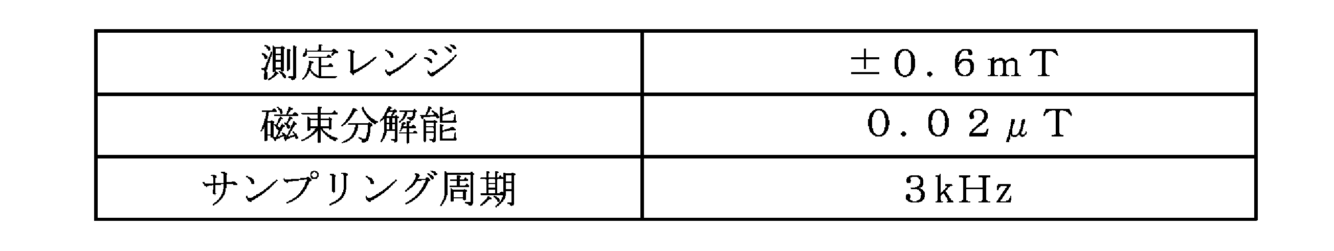
情報取得部の一例をなすタグリーダ3は、図7のごとく、磁気マーカ1が備えるRFIDタグ15に対して電力を供給する電力供給部31と、RFIDタグ15が無線送信するコード情報を取得する情報取得部33と、を含んで構成されている。電力供給部31は、ループコイル310に電流を供給して磁界を発生させ、電磁誘導により電力を伝送する電子回路である。情報取得部33は、ループアンテナ330を利用してRFIDタグ15が送信する電波を受信し、復調によりコード情報を取り出す電子回路である。
車両5の走行中では、車載ユニット2Aの磁気センサ2を利用して磁気マーカ1の検出処理が繰り返し実行される(S101)。磁気センサ2により磁気マーカ1が検出されると(S102:YES)、車載ユニット2Aは、タグリーダ3に電力伝送を実施させ、これにより磁気マーカ1のRFIDタグ15に動作電力を供給する(S103)。車載ユニット2Aは、RFIDタグ15の動作に応じて開始される無線送信に同期してタグリーダ3に受信・復調処理を開始させ(S104)、RFIDタグ15が送信するコード情報を取得する。
道路の勾配や、前方の道路の曲率や、走行中の車線の種別や、法定速度等の情報を位置情報に含めることも良い。このような詳細な情報があれば、例えば、運転者に注意を促す運転支援や、急勾配の下り坂や急カーブの手前ではギアを一段落としてエンジンブレーキが効く状態にする等の車両制御を実行可能である。
例えば、ショッピングセンタなどの自走式立体駐車場などの通路に磁気マーカ1を敷設しておき、階数などの高さ情報を車両5側に提供することも良い。例えばGPS等では、建物内の階数の特定が容易ではない。車両が所在する階数が不明であれば、仮に階数の指定付きの空き枠情報がインフラ側から提供されても、その空き枠への経路案内を精度高く行うことは難しい。階数を特定可能な高さ情報の提供が有れば、自走式立体駐車場内での空き枠への精度の高い路案内を実現できる。
交差点の情報や、分岐路の情報や、合流路の情報などの交通情報を車両5側に提供することも良い。例えば、交差点や分岐路や合流路など道路(走行路)上の特徴あるポイントに磁気マーカ1を設置し、道路形状に関する交通情報を基地局6から提供すると良い。交通情報を利用する運転支援としては、運転者に注意を促す表示や警報音等による交通情報の提示や、ブレーキ制御やステアリング制御等の各種の運転支援制御がある。例えば交差点の停止線と磁気マーカ1との距離が規定されていれば、停止線に停止させるためのブレーキ制御を精度高く実行できる。また、例えば分岐路の開始位置と磁気マーカ1との距離が規定されていれば、分岐路で分岐させるための運転支援制御を精度高く実行できる。なお、交差点や分岐路と磁気マーカ1との距離の情報を、基地局6から提供する情報に含めることも良い。
なお、RFIDタグ15及びタグリーダ3について、電力伝送のためのアンテナと、情報を送信あるいは受信するためのアンテナとを共用することも良い。
本例は、実施例1の磁気マーカに代えて、表面側に画像的なパターンが形成された磁気マーカ1を採用した例である。この内容について図9及び図10を参照して説明する。
図9の磁気マーカ1は、形状的な仕様や磁気的な仕様が実施例1と同様であり、樹脂モールド等の表面処理も同様である。相違点は、RFIDタグ15が表面側に積層配置されておらず、代わりとして、情報提供部の一例をなす画像的なパターンであるコード画像18が印刷等により形成されている点にある。また、本例の運転支援システムを構成する車載ユニットは、実施例1のタグリーダに代えて、路面63を撮像するカメラと、磁気マーカ1の撮像画像に画像処理を施してコード画像18からコード情報を読み取る画像ECUと、の組み合わせ(図示略)を情報取得部の一例として備えている。
車両5側のカメラは、路面63に敷設された磁気マーカ1の表面を撮像できるよう、下方にレンズを向けて取り付けられている。画像ECUは、磁気マーカ1を磁気的に検出できたときにカメラの撮像画像を取り込んで画像処理を施し、コード画像領域の切り出し、及びコード画像18が表すコード情報の読み取りを実行するように構成されている。
また、例えばコード画像中の黒い部分のみに孔を設けた白色シートを被せて、孔を介して磁石シート11の黒色を外部から見えるようにし、白色シートの白い部分との対比によりコード画像を表示することも良い。
また、1箇所の磁気マーカ1で提供可能な情報量が目的に対して十分ではない場合であれば、車両5の進行方向に隣り合う2個など複数の磁気マーカ1の画像的なパターンを組み合わせて1つのコード情報を表すこともできる。
なお、その他の構成及び作用効果については実施例1と同様である。
本例は、実施例1の運転支援システムを基にして、コード情報を車両側に提供するための構成を変更した例である。コード情報の受信に応じて基地局が車両側に提供する情報は、実施例1と同様の2次元的な位置情報である。この内容について、図11~図19を参照して説明する。
(2)磁気検出部:マーカ敷設箇所64と特定された箇所について磁気マーカ1の検出を実行する。
(3)情報取得部:複数の磁気マーカ1の検出結果の組み合わせによるコード情報を読み取り、対応する位置情報を基地局から取得する。
(4)支援部:磁気マーカ1を利用した運転の支援を実行する。
敷設箇所特定部は、図14の通り、車両5のタイヤが1回転する毎にパルス信号を発生する車速センサ459と、マーカ敷設箇所64の位置を特定するための敷設データを格納した敷設データベース451と、マーカ敷設箇所64を特定する車載ユニット45と、を含んで構成されている。敷設データには、情報提供区間の開始位置を表すコード(上記の開始位置特定区間の磁気マーカ1の敷設態様の組み合わせ)や、マーカ敷設箇所64の間隔である規定距離を表す距離データ等が含まれている。
磁気検出部は、磁気センサ2を含めて構成されている。磁気センサ2は、実施例1と同様の仕様のものであり、車両に対する取付仕様も同様である。本例の磁気センサ2は、情報提供区間(図12)においては、車両5がマーカ敷設箇所64に到達する毎に磁気マーカ1の検出を試み、検出できたときには磁気マーカ1の極性を判定する。なお、磁気センサ2で極性を判定する方法については後で説明する。
情報取得部は、磁気マーカ1側からコード情報を読み取る車載ユニット45(図14)と、基地局にコード情報を送信し対応する位置情報の返信を受ける路車間通信ユニット41(図14)と、の組み合わせにより構成されている。車載ユニット45は、情報提供区間(図12参照。)内の各マーカ敷設箇所64における磁気マーカ1の敷設態様(磁気マーカ1の有無及び極性)の組み合わせを表すコード情報を読み取るユニットである。なお、本例では、磁気マーカ1の敷設態様が表すコード情報として、情報提供区間及び開始位置特定区間の両方で5桁のコードを採用している。なお、基地局が返信する位置情報は、情報提供区間を構成する5箇所のマーカ敷設箇所64のうちの最後のマーカ敷設箇所の絶対位置を表す情報となっている。
(4)支援部
本例の支援部は、基地局から提供された位置情報を利用する実施例1と同様、運転支援システムの一例であるナビゲーションシステムを実行する。
上記の情報提供区間(図12参照。)が設定された道路を車両5が走行中のとき、車載ユニット45は、情報提供区間の開始位置を特定するまで、磁気マーカ1の検出を繰り返し実行する(S101)。車載ユニット45は、磁気マーカ1を検出すると(S101:YES)、磁気マーカ1の敷設態様の組み合わせを記憶させる5桁のコードの各桁を上位に順送りして最下位ビットを空ビットにし、新たに検出した磁気マーカ1の値を順次、セットする(S102)。なお、運転支援システム1Aでは、N極が検出される敷設態様が1の値、S極が検出される敷設態様が2の値、磁気マーカ無しの敷設態様がゼロ値として取り扱われる。
本例では、車線630の長手方向に沿ってマーカ敷設箇所を1次元的に配列しているが、図18のようにマーカ敷設箇所64を車線の幅方向に1次元的に配列することも良い。この場合には、磁気センサ2を車幅方向に複数配列したセンサユニット2Uを車両5に取り付けると良い。さらに、図19のようにマーカ敷設箇所64を2次元的に配列しても良い。この場合には、より多くの情報を短い距離で提供できるようになる。
なお、その他の構成及び作用効果については、実施例1あるいは実施例2と同様である。
本例は、実施例3を基にして、複数の磁気マーカの組み合わせによるコード情報の提供方法を変更した例である。コード情報を提供する情報提供区間の開始位置を特定する開始位置特定区間の構成は実施例3と同様である一方、情報提供区間の構成が相違している。
情報提供区間に敷設される各磁気マーカは、極性が一定である一方、隣り合う2つの磁気マーカ1の敷設間隔が相違している。敷設間隔としては、1.6m、1.8m、2.0m、2.2m、2.4m等が設定されている。そして、各敷設間隔に対応するビット値としては、1~5の値が設定されている。
なお、情報提供区間において車線の長手方向に配置された各敷設箇所において、車幅方向に複数の磁気マーカを敷設し、その間隔の広い狭いによって情報を表すこともできる。
情報提供区間に敷設される各磁気マーカは、極性が同じである一方、発生する磁界の強度が相違している。磁界強度としては、強い、弱いが設定されている。なお、弱い方の磁気マーカについても磁気センサで十分に検出可能となっている。
情報提供区間に敷設される各磁気マーカは極性が同じである一方、1箇所に敷設される磁気マーカの数が相違している。情報提供区間において2m間隔で配置された各敷設箇所では、例えば1個から3個の磁気マーカが横並びで配置されている。車両側では、10個程度の磁気センサが横並びで配列され、幅方向に配置された磁気マーカの個数を特定可能である。この構成では、横並びで配置された磁気マーカの個数がビット値を表し、情報提供区間を構成する各敷設箇所に配置された磁気マーカの個数によってコード情報が表される。
さらに、マーカ敷設箇所における磁気マーカの配置形状、あるいはその組合せによりコード情報を表すことも良い。配置形状としては、横1列、縦1列、横2列、縦2列、三角形、菱形等の形状がある。また、複数のマーカ敷設箇所の配置形状の組み合わせによりコード情報を表すことも良い。
なお、その他の構成及び作用効果については他の実施例と同様である。
1A 運転支援システム
11 磁石シート(磁気発生部)
12 樹脂モールド
15 RFIDタグ(無線タグ、情報提供部)
18 コード画像(情報提供部)
19 塗り分けパターン(情報提供部)
2A 車載ユニット
2 磁気センサ(磁気検出部)
21 MI素子
3 タグリーダ(情報取得部)
41 路車間通信ユニット
45 車載ユニット
459 車速センサ
5 車両
50 車体フロア(底面)
6 基地局
60 通信ユニット
63 路面
64 マーカ敷設箇所
Claims (13)
- 磁気的に検出可能であると共にコード情報を車両側に提供可能なように走行路に敷設された磁気マーカと、
該磁気マーカを磁気的に検出可能であると共に前記コード情報を読み取り可能に構成された車両と、
前記コード情報を読み取った車両から該コード情報を受信したとき、対応する情報を返信するように構成された基地局と、を含む運転支援システム。 - 請求項1において、前記磁気マーカは、周辺磁界を発生する磁気発生部のほかに、前記コード情報を車両側に提供する情報提供部を備えている運転支援システム。
- 請求項2において、前記情報提供部は、前記磁気マーカに保持された無線タグである運転支援システム。
- 請求項3において、前記無線タグは、710~960MHzの周波数帯域を使用する無線タグである運転支援システム。
- 請求項3または4において、前記磁気発生部は、磁気発生源として磁性粉末を含んで成形された磁石を有している運転支援システム。
- 請求項1~5のいずれか1項において、前記情報提供部は、前記磁気マーカの表面に形成されて画像的に読み取り可能なパターンである運転支援システム。
- 請求項1~6のいずれか1項において、走行路には、磁気マーカを敷設する可能性があるマーカ敷設箇所が1次元的あるいは2次元的に設定され、各マーカ敷設箇所では、前記磁気マーカを敷設しないという態様を含む複数の敷設態様の中のいずれかが択一的に選択され、複数の前記マーカ敷設箇所における磁気マーカの敷設態様の組み合わせにより車両側に前記コード情報を提供するように構成された運転支援システム。
- 請求項7において、前記磁気マーカの敷設態様には、表面側にN極が位置するように磁気マーカを敷設する態様、及び表面側にS極が位置するように磁気マーカを敷設する態様が含まれている運転支援システム。
- 請求項7又は8において、前記車両は、複数の前記マーカ敷設箇所を位置的に特定する敷設箇所特定部と、複数の前記マーカ敷設箇所について前記磁気マーカの敷設態様を検出して前記コード情報を取得する情報取得部と、を備えている運転支援システム。
- 請求項1~9のいずれか1項において、前記コード情報は、車幅方向あるいは走行路の長手方向に配列された2つの磁気マーカ間の距離により表される情報である運転支援システム。
- 請求項1~10のいずれか1項において、前記コード情報は、各磁気マーカが車両側に作用する磁気強度により表される情報である運転支援システム。
- 請求項1~11のいずれか1項において、前記コード情報は、前記磁気マーカの配置により表される情報である運転支援システム。
- 請求項1~12のいずれか1項において、前記車両は、絶対位置を測位する測位部と、車両が所在する絶対位置を利用した運転支援情報を運転者側に提示する支援情報提示部と、を備え、
前記基地局が前記車両に返信する情報には、当該車両が所在する絶対位置を特定可能な位置情報が含まれている運転支援システム。
Priority Applications (6)
| Application Number | Priority Date | Filing Date | Title |
|---|---|---|---|
| SG11201809405RA SG11201809405RA (en) | 2016-04-28 | 2017-03-30 | Driving assistance system |
| US16/097,477 US11057752B2 (en) | 2016-04-28 | 2017-03-30 | Driving assistance system |
| JP2018514210A JP6947171B2 (ja) | 2016-04-28 | 2017-03-30 | 運転支援システム |
| EP17789169.4A EP3451310B1 (en) | 2016-04-28 | 2017-03-30 | Driving assistance system |
| CN201780025341.6A CN109074732B (zh) | 2016-04-28 | 2017-03-30 | 驾驶支援系统 |
| US17/243,583 US11356822B2 (en) | 2016-04-28 | 2021-04-29 | Driving assistance system |
Applications Claiming Priority (2)
| Application Number | Priority Date | Filing Date | Title |
|---|---|---|---|
| JP2016090608 | 2016-04-28 | ||
| JP2016-090608 | 2016-04-28 |
Related Child Applications (2)
| Application Number | Title | Priority Date | Filing Date |
|---|---|---|---|
| US16/097,477 A-371-Of-International US11057752B2 (en) | 2016-04-28 | 2017-03-30 | Driving assistance system |
| US17/243,583 Continuation US11356822B2 (en) | 2016-04-28 | 2021-04-29 | Driving assistance system |
Publications (1)
| Publication Number | Publication Date |
|---|---|
| WO2017187881A1 true WO2017187881A1 (ja) | 2017-11-02 |
Family
ID=60160420
Family Applications (1)
| Application Number | Title | Priority Date | Filing Date |
|---|---|---|---|
| PCT/JP2017/013346 WO2017187881A1 (ja) | 2016-04-28 | 2017-03-30 | 運転支援システム |
Country Status (6)
| Country | Link |
|---|---|
| US (2) | US11057752B2 (ja) |
| EP (1) | EP3451310B1 (ja) |
| JP (1) | JP6947171B2 (ja) |
| CN (1) | CN109074732B (ja) |
| SG (1) | SG11201809405RA (ja) |
| WO (1) | WO2017187881A1 (ja) |
Cited By (13)
| Publication number | Priority date | Publication date | Assignee | Title |
|---|---|---|---|---|
| JP2019124555A (ja) * | 2018-01-16 | 2019-07-25 | 愛知製鋼株式会社 | 車両位置管理システム及び車両位置管理方法 |
| WO2019142740A1 (ja) * | 2018-01-16 | 2019-07-25 | 愛知製鋼株式会社 | 運転支援システム |
| WO2019156194A1 (ja) * | 2018-02-12 | 2019-08-15 | 愛知製鋼株式会社 | 車両用システム |
| JP2020017035A (ja) * | 2018-07-25 | 2020-01-30 | 愛知製鋼株式会社 | 車両用システム |
| JP2020057301A (ja) * | 2018-10-04 | 2020-04-09 | 愛知製鋼株式会社 | 磁気マーカシステム |
| CN112041909A (zh) * | 2018-05-02 | 2020-12-04 | 爱知制钢株式会社 | 自动停车系统 |
| CN112109706A (zh) * | 2019-06-21 | 2020-12-22 | 华为技术有限公司 | 基于磁感通信的车辆控制的装置和方法 |
| JPWO2020138465A1 (ja) * | 2018-12-28 | 2021-11-04 | 愛知製鋼株式会社 | 車両及び車両用の診断システム |
| WO2021261569A1 (ja) * | 2020-06-26 | 2021-12-30 | 愛知製鋼株式会社 | マーカシステム及び磁気マーカの検出方法 |
| WO2021261570A1 (ja) * | 2020-06-26 | 2021-12-30 | 愛知製鋼株式会社 | 車両向けシステム及び情報読取方法 |
| US20220028261A1 (en) * | 2018-12-28 | 2022-01-27 | Aichi Steel Corporation | Magnetic marker system |
| WO2022210203A1 (ja) * | 2021-04-01 | 2022-10-06 | 愛知製鋼株式会社 | 磁気マーカシステム、及び磁気マーカシステムの設計方法 |
| JP7410150B2 (ja) | 2019-07-23 | 2024-01-09 | 本田技研工業株式会社 | 自律作業機、自律作業機の制御方法及びプログラム |
Families Citing this family (12)
| Publication number | Priority date | Publication date | Assignee | Title |
|---|---|---|---|---|
| JP6928307B2 (ja) * | 2017-03-28 | 2021-09-01 | 愛知製鋼株式会社 | マーカ検出システム及びマーカ検出方法 |
| JP6920975B2 (ja) * | 2017-12-12 | 2021-08-18 | 愛知製鋼株式会社 | 施工装置、施工方法、及び施工システム |
| JP6965815B2 (ja) * | 2018-04-12 | 2021-11-10 | 愛知製鋼株式会社 | マーカ検出システム、及びマーカ検出システムの運用方法 |
| JP7151192B2 (ja) * | 2018-06-11 | 2022-10-12 | 愛知製鋼株式会社 | 磁気マーカの施工方法 |
| JP7151191B2 (ja) * | 2018-06-11 | 2022-10-12 | 愛知製鋼株式会社 | 磁気マーカ |
| US11604476B1 (en) * | 2018-10-05 | 2023-03-14 | Glydways Inc. | Road-based vehicle guidance system |
| SG11202107068PA (en) * | 2018-12-28 | 2021-07-29 | Aichi Steel Corp | Correction method for gyro sensor |
| US10909716B2 (en) * | 2019-02-22 | 2021-02-02 | Toyota Jidosha Kabushiki Kaish | Vehicle localization using marker devices |
| WO2020171232A1 (ja) * | 2019-02-23 | 2020-08-27 | 愛知製鋼株式会社 | 磁気マーカの診断システム及び診断方法 |
| EP4006681A4 (en) * | 2019-07-23 | 2022-11-16 | Honda Motor Co., Ltd. | AUTONOMOUS WORK MACHINE, CONTROL DEVICE, METHOD FOR CONTROLLING AN AUTONOMOUS WORK MACHINE, METHOD FOR OPERATING A CONTROL DEVICE, AND PROGRAM |
| KR102393837B1 (ko) * | 2021-09-13 | 2022-05-06 | 주식회사 정석케미칼 | 자성도료 차선 기반 차량 제어 신호 생성 방법 및 이를 위한 장치 |
| US20230160699A1 (en) * | 2021-11-22 | 2023-05-25 | Here Global B.V. | Method and apparatus for vehicle localization and enhanced vehicle operation |
Citations (3)
| Publication number | Priority date | Publication date | Assignee | Title |
|---|---|---|---|---|
| JPH0962346A (ja) * | 1995-08-23 | 1997-03-07 | Toyota Motor Corp | 自動操舵システム |
| JP2005092572A (ja) * | 2003-09-18 | 2005-04-07 | Clarion Co Ltd | 車両位置検索システム及びこれに用いる車載用機器 |
| JP2007233604A (ja) * | 2006-02-28 | 2007-09-13 | Toyota Motor Corp | 道路情報取得装置、及びこれを利用した車両用走行制御装置、並びに道路交通システム |
Family Cites Families (26)
| Publication number | Priority date | Publication date | Assignee | Title |
|---|---|---|---|---|
| CA1048121A (en) * | 1974-04-18 | 1979-02-06 | Willis T. Lawrence | Automatic vehicle monitoring system |
| US5002145A (en) * | 1988-01-29 | 1991-03-26 | Nec Corporation | Method and apparatus for controlling automated guided vehicle |
| JPH0358179A (ja) * | 1989-07-26 | 1991-03-13 | Nec Corp | パターン読取り装置 |
| US5369591A (en) * | 1993-03-11 | 1994-11-29 | Broxmeyer; Charles | Vehicle longitudinal control and collision avoidance system for an automated highway system |
| JP3191621B2 (ja) * | 1995-03-14 | 2001-07-23 | トヨタ自動車株式会社 | 車両走行誘導システム |
| US7202776B2 (en) * | 1997-10-22 | 2007-04-10 | Intelligent Technologies International, Inc. | Method and system for detecting objects external to a vehicle |
| JP3588922B2 (ja) * | 1996-07-08 | 2004-11-17 | トヨタ自動車株式会社 | 車両走行誘導システム |
| JP3122761B2 (ja) * | 1998-07-31 | 2001-01-09 | 建設省土木研究所長 | 道路マーカ着磁装置 |
| US6441741B1 (en) * | 1999-05-17 | 2002-08-27 | Avid Identification Systems, Inc. | Overmolded transponder |
| JP2005202478A (ja) | 2004-01-13 | 2005-07-28 | Denso Corp | 車両用自動走行システム |
| WO2006102300A2 (en) * | 2005-03-18 | 2006-09-28 | Gatekeeper Systems, Inc. | Navigation systems and methods for wheeled objects |
| CN101496073A (zh) * | 2006-07-26 | 2009-07-29 | 耐克斯特株式会社 | 磁性标识器及其制造装置 |
| JP2009134438A (ja) * | 2007-11-29 | 2009-06-18 | Toyota Motor Corp | 搬送用自走車の稼動管理システム及び稼動管理方法 |
| US8223014B2 (en) * | 2008-07-02 | 2012-07-17 | Essence Security International Ltd. | Energy-conserving triggered ID system and method |
| CN101603830A (zh) * | 2009-06-23 | 2009-12-16 | 广州市井源机电设备有限公司 | 自动导航小车系统及多任务控制方法 |
| EP2360544B1 (en) * | 2010-02-19 | 2018-01-03 | 2 Getthere B.V. | System for determining the position of a vehicle, vehicle therewith, and method therefor |
| JP5433525B2 (ja) * | 2010-08-06 | 2014-03-05 | 株式会社日立製作所 | 車両走行支援装置及び道路標示の作成方法 |
| US8862395B2 (en) * | 2011-01-31 | 2014-10-14 | Raytheon Company | Coded marker navigation system and method |
| US10273704B2 (en) * | 2011-12-22 | 2019-04-30 | Park Plus, Inc. | Automated parking garage/self-storage apparatus |
| CN102661745A (zh) * | 2012-04-11 | 2012-09-12 | 廖海龙 | 一种带磁条和rfid标签自动行走机器人的导航方式 |
| CN202838578U (zh) * | 2012-05-17 | 2013-03-27 | 宁波讯强电子科技有限公司 | 一种多片共振片的窄型声磁防盗标签 |
| US9197705B2 (en) * | 2013-04-12 | 2015-11-24 | Samsung Electronics Co., Ltd. | Method and apparatus for supporting driving using wireless communication network and system thereof |
| CN103279774B (zh) * | 2013-04-17 | 2016-03-30 | 中国科学院自动化研究所 | 移动电子标签性能检测系统及检测方法 |
| US20150247719A1 (en) * | 2014-03-03 | 2015-09-03 | Tomorrow's Transportation Today | Position sensing system for intelligent vehicle guidance |
| US20150294430A1 (en) * | 2014-04-15 | 2015-10-15 | Tomorrow's Transportation Today | Dynamic dispatching and schedule management methods for an intelligent transit system with electronic guided buses |
| US9892296B2 (en) * | 2014-11-12 | 2018-02-13 | Joseph E. Kovarik | Method and system for autonomous vehicles |
-
2017
- 2017-03-30 WO PCT/JP2017/013346 patent/WO2017187881A1/ja active Application Filing
- 2017-03-30 JP JP2018514210A patent/JP6947171B2/ja active Active
- 2017-03-30 EP EP17789169.4A patent/EP3451310B1/en active Active
- 2017-03-30 SG SG11201809405RA patent/SG11201809405RA/en unknown
- 2017-03-30 US US16/097,477 patent/US11057752B2/en active Active
- 2017-03-30 CN CN201780025341.6A patent/CN109074732B/zh active Active
-
2021
- 2021-04-29 US US17/243,583 patent/US11356822B2/en active Active
Patent Citations (3)
| Publication number | Priority date | Publication date | Assignee | Title |
|---|---|---|---|---|
| JPH0962346A (ja) * | 1995-08-23 | 1997-03-07 | Toyota Motor Corp | 自動操舵システム |
| JP2005092572A (ja) * | 2003-09-18 | 2005-04-07 | Clarion Co Ltd | 車両位置検索システム及びこれに用いる車載用機器 |
| JP2007233604A (ja) * | 2006-02-28 | 2007-09-13 | Toyota Motor Corp | 道路情報取得装置、及びこれを利用した車両用走行制御装置、並びに道路交通システム |
Cited By (38)
| Publication number | Priority date | Publication date | Assignee | Title |
|---|---|---|---|---|
| JP2019125136A (ja) * | 2018-01-16 | 2019-07-25 | 愛知製鋼株式会社 | 運転支援システム |
| WO2019142737A1 (ja) * | 2018-01-16 | 2019-07-25 | 愛知製鋼株式会社 | 車両位置管理システム及び車両位置管理方法 |
| CN111587446B (zh) * | 2018-01-16 | 2024-04-12 | 爱知制钢株式会社 | 驾驶支援系统 |
| CN111602029B (zh) * | 2018-01-16 | 2023-10-27 | 爱知制钢株式会社 | 车辆位置管理系统及车辆位置管理方法 |
| US11631111B2 (en) | 2018-01-16 | 2023-04-18 | Aichi Steel Corporation | Driving support system |
| JP2019124555A (ja) * | 2018-01-16 | 2019-07-25 | 愛知製鋼株式会社 | 車両位置管理システム及び車両位置管理方法 |
| JP7091668B2 (ja) | 2018-01-16 | 2022-06-28 | 愛知製鋼株式会社 | 運転支援システム |
| JP7047392B2 (ja) | 2018-01-16 | 2022-04-05 | 愛知製鋼株式会社 | 車両位置管理システム及び車両位置管理方法 |
| CN111587446A (zh) * | 2018-01-16 | 2020-08-25 | 爱知制钢株式会社 | 驾驶支援系统 |
| CN111602029A (zh) * | 2018-01-16 | 2020-08-28 | 爱知制钢株式会社 | 车辆位置管理系统及车辆位置管理方法 |
| EP3742119A4 (en) * | 2018-01-16 | 2022-02-09 | Aichi Steel Corporation | VEHICLE LOCATION MANAGEMENT SYSTEM AND VEHICLE LOCATION MANAGEMENT METHOD |
| US11164217B2 (en) | 2018-01-16 | 2021-11-02 | Aichi Steel Corporation | Driving support system |
| WO2019142740A1 (ja) * | 2018-01-16 | 2019-07-25 | 愛知製鋼株式会社 | 運転支援システム |
| US11131561B2 (en) | 2018-01-16 | 2021-09-28 | Aichi Steel Corporation | Vehicle position management system and vehicle position management method |
| EP3742382A4 (en) * | 2018-01-16 | 2021-10-06 | Aichi Steel Corporation | DRIVER ASSISTANCE SYSTEM |
| WO2019156194A1 (ja) * | 2018-02-12 | 2019-08-15 | 愛知製鋼株式会社 | 車両用システム |
| CN112041909A (zh) * | 2018-05-02 | 2020-12-04 | 爱知制钢株式会社 | 自动停车系统 |
| US11801827B2 (en) | 2018-05-02 | 2023-10-31 | Aichi Steel Corporation | Automatic parking system |
| EP3789985A4 (en) * | 2018-05-02 | 2022-03-02 | Aichi Steel Corporation | AUTOMATIC PARKING SYSTEM |
| JP2020017035A (ja) * | 2018-07-25 | 2020-01-30 | 愛知製鋼株式会社 | 車両用システム |
| JP7115098B2 (ja) | 2018-07-25 | 2022-08-09 | 愛知製鋼株式会社 | 車両用システム |
| US11687088B2 (en) | 2018-07-25 | 2023-06-27 | Aichi Steel Corporation | Vehicular system |
| WO2020071182A1 (ja) * | 2018-10-04 | 2020-04-09 | 愛知製鋼株式会社 | 磁気マーカシステム |
| CN112753054A (zh) * | 2018-10-04 | 2021-05-04 | 爱知制钢株式会社 | 磁性标识器系统 |
| JP7255127B2 (ja) | 2018-10-04 | 2023-04-11 | 愛知製鋼株式会社 | 磁気マーカシステム |
| JP2020057301A (ja) * | 2018-10-04 | 2020-04-09 | 愛知製鋼株式会社 | 磁気マーカシステム |
| EP3862988A4 (en) * | 2018-10-04 | 2022-06-22 | Aichi Steel Corporation | MAGNETIC MARKING SYSTEM |
| US20220028261A1 (en) * | 2018-12-28 | 2022-01-27 | Aichi Steel Corporation | Magnetic marker system |
| JP7389359B2 (ja) | 2018-12-28 | 2023-11-30 | 愛知製鋼株式会社 | 車両及び車両用の診断システム |
| US11875675B2 (en) * | 2018-12-28 | 2024-01-16 | Aichi Steel Corporation | Vehicle and vehicular diagnostic system |
| US20220068129A1 (en) * | 2018-12-28 | 2022-03-03 | Aichi Steel Corporation | Vehicle and vehicular diagnostic system |
| JPWO2020138465A1 (ja) * | 2018-12-28 | 2021-11-04 | 愛知製鋼株式会社 | 車両及び車両用の診断システム |
| US11862014B2 (en) * | 2018-12-28 | 2024-01-02 | Aichi Steel Corporation | Magnetic marker system |
| CN112109706A (zh) * | 2019-06-21 | 2020-12-22 | 华为技术有限公司 | 基于磁感通信的车辆控制的装置和方法 |
| JP7410150B2 (ja) | 2019-07-23 | 2024-01-09 | 本田技研工業株式会社 | 自律作業機、自律作業機の制御方法及びプログラム |
| WO2021261570A1 (ja) * | 2020-06-26 | 2021-12-30 | 愛知製鋼株式会社 | 車両向けシステム及び情報読取方法 |
| WO2021261569A1 (ja) * | 2020-06-26 | 2021-12-30 | 愛知製鋼株式会社 | マーカシステム及び磁気マーカの検出方法 |
| WO2022210203A1 (ja) * | 2021-04-01 | 2022-10-06 | 愛知製鋼株式会社 | 磁気マーカシステム、及び磁気マーカシステムの設計方法 |
Also Published As
| Publication number | Publication date |
|---|---|
| CN109074732A (zh) | 2018-12-21 |
| US20210250738A1 (en) | 2021-08-12 |
| EP3451310A4 (en) | 2019-03-20 |
| JP6947171B2 (ja) | 2021-10-13 |
| SG11201809405RA (en) | 2018-11-29 |
| EP3451310B1 (en) | 2020-10-28 |
| JPWO2017187881A1 (ja) | 2019-02-28 |
| US11057752B2 (en) | 2021-07-06 |
| EP3451310A1 (en) | 2019-03-06 |
| CN109074732B (zh) | 2021-11-02 |
| US11356822B2 (en) | 2022-06-07 |
| US20190098468A1 (en) | 2019-03-28 |
Similar Documents
| Publication | Publication Date | Title |
|---|---|---|
| WO2017187881A1 (ja) | 運転支援システム | |
| CN109074731B (zh) | 磁性标识器及驾驶支援系统 | |
| JP7140220B2 (ja) | 磁気マーカ及びマーカシステム | |
| WO2018043273A1 (ja) | 車両用システム及び進路推定方法 | |
| JP6733289B2 (ja) | 運転支援システム | |
| CN110419067B (zh) | 标识器系统 | |
| CN112041909A (zh) | 自动停车系统 | |
| WO2019142737A1 (ja) | 車両位置管理システム及び車両位置管理方法 | |
| WO2017069089A1 (ja) | 磁気マーカ及び磁気マーカ検出システム | |
| WO2021261569A1 (ja) | マーカシステム及び磁気マーカの検出方法 | |
| WO2022210201A1 (ja) | 情報取得方法及び車両用システム | |
| KR20240024916A (ko) | 차량용 시스템 |
Legal Events
| Date | Code | Title | Description |
|---|---|---|---|
| ENP | Entry into the national phase |
Ref document number: 2018514210 Country of ref document: JP Kind code of ref document: A |
|
| NENP | Non-entry into the national phase |
Ref country code: DE |
|
| 121 | Ep: the epo has been informed by wipo that ep was designated in this application |
Ref document number: 17789169 Country of ref document: EP Kind code of ref document: A1 |
|
| WWE | Wipo information: entry into national phase |
Ref document number: 2017789169 Country of ref document: EP |
|
| ENP | Entry into the national phase |
Ref document number: 2017789169 Country of ref document: EP Effective date: 20181128 |