WO2017183173A1 - エネルギ吸収構造 - Google Patents
エネルギ吸収構造 Download PDFInfo
- Publication number
- WO2017183173A1 WO2017183173A1 PCT/JP2016/062720 JP2016062720W WO2017183173A1 WO 2017183173 A1 WO2017183173 A1 WO 2017183173A1 JP 2016062720 W JP2016062720 W JP 2016062720W WO 2017183173 A1 WO2017183173 A1 WO 2017183173A1
- Authority
- WO
- WIPO (PCT)
- Prior art keywords
- energy absorbing
- vehicle body
- connecting member
- bumper
- mounting plate
- Prior art date
Links
- 239000000463 material Substances 0.000 claims abstract description 18
- 239000011347 resin Substances 0.000 claims abstract description 12
- 229920005989 resin Polymers 0.000 claims abstract description 12
- 239000000835 fiber Substances 0.000 claims description 10
- 229910052751 metal Inorganic materials 0.000 claims description 6
- 239000002184 metal Substances 0.000 claims description 6
- 230000002787 reinforcement Effects 0.000 description 30
- 239000006096 absorbing agent Substances 0.000 description 22
- 238000003466 welding Methods 0.000 description 7
- 210000003195 fascia Anatomy 0.000 description 6
- 238000012986 modification Methods 0.000 description 4
- 230000004048 modification Effects 0.000 description 4
- 239000000853 adhesive Substances 0.000 description 3
- 230000001070 adhesive effect Effects 0.000 description 3
- XEEYBQQBJWHFJM-UHFFFAOYSA-N Iron Chemical compound [Fe] XEEYBQQBJWHFJM-UHFFFAOYSA-N 0.000 description 2
- 229920000297 Rayon Polymers 0.000 description 2
- 238000010521 absorption reaction Methods 0.000 description 2
- 229910052782 aluminium Inorganic materials 0.000 description 2
- XAGFODPZIPBFFR-UHFFFAOYSA-N aluminium Chemical compound [Al] XAGFODPZIPBFFR-UHFFFAOYSA-N 0.000 description 2
- 239000003365 glass fiber Substances 0.000 description 2
- 238000003780 insertion Methods 0.000 description 2
- 230000037431 insertion Effects 0.000 description 2
- 239000011159 matrix material Substances 0.000 description 2
- 238000005192 partition Methods 0.000 description 2
- 239000002964 rayon Substances 0.000 description 2
- 229920000049 Carbon (fiber) Polymers 0.000 description 1
- 230000005540 biological transmission Effects 0.000 description 1
- 239000004917 carbon fiber Substances 0.000 description 1
- 238000005470 impregnation Methods 0.000 description 1
- 229910052742 iron Inorganic materials 0.000 description 1
- 238000000034 method Methods 0.000 description 1
- 239000012783 reinforcing fiber Substances 0.000 description 1
- 230000035939 shock Effects 0.000 description 1
- 239000000126 substance Substances 0.000 description 1
- 239000013585 weight reducing agent Substances 0.000 description 1
- 239000002759 woven fabric Substances 0.000 description 1
Images


Classifications
-
- B—PERFORMING OPERATIONS; TRANSPORTING
- B60—VEHICLES IN GENERAL
- B60R—VEHICLES, VEHICLE FITTINGS, OR VEHICLE PARTS, NOT OTHERWISE PROVIDED FOR
- B60R19/00—Wheel guards; Radiator guards, e.g. grilles; Obstruction removers; Fittings damping bouncing force in collisions
- B60R19/02—Bumpers, i.e. impact receiving or absorbing members for protecting vehicles or fending off blows from other vehicles or objects
- B60R19/18—Bumpers, i.e. impact receiving or absorbing members for protecting vehicles or fending off blows from other vehicles or objects characterised by the cross-section; Means within the bumper to absorb impact
-
- B—PERFORMING OPERATIONS; TRANSPORTING
- B60—VEHICLES IN GENERAL
- B60R—VEHICLES, VEHICLE FITTINGS, OR VEHICLE PARTS, NOT OTHERWISE PROVIDED FOR
- B60R19/00—Wheel guards; Radiator guards, e.g. grilles; Obstruction removers; Fittings damping bouncing force in collisions
- B60R19/02—Bumpers, i.e. impact receiving or absorbing members for protecting vehicles or fending off blows from other vehicles or objects
- B60R19/24—Arrangements for mounting bumpers on vehicles
- B60R19/26—Arrangements for mounting bumpers on vehicles comprising yieldable mounting means
- B60R19/34—Arrangements for mounting bumpers on vehicles comprising yieldable mounting means destroyed upon impact, e.g. one-shot type
-
- B—PERFORMING OPERATIONS; TRANSPORTING
- B60—VEHICLES IN GENERAL
- B60R—VEHICLES, VEHICLE FITTINGS, OR VEHICLE PARTS, NOT OTHERWISE PROVIDED FOR
- B60R19/00—Wheel guards; Radiator guards, e.g. grilles; Obstruction removers; Fittings damping bouncing force in collisions
- B60R19/02—Bumpers, i.e. impact receiving or absorbing members for protecting vehicles or fending off blows from other vehicles or objects
- B60R19/24—Arrangements for mounting bumpers on vehicles
- B60R19/26—Arrangements for mounting bumpers on vehicles comprising yieldable mounting means
-
- B—PERFORMING OPERATIONS; TRANSPORTING
- B60—VEHICLES IN GENERAL
- B60R—VEHICLES, VEHICLE FITTINGS, OR VEHICLE PARTS, NOT OTHERWISE PROVIDED FOR
- B60R19/00—Wheel guards; Radiator guards, e.g. grilles; Obstruction removers; Fittings damping bouncing force in collisions
- B60R19/02—Bumpers, i.e. impact receiving or absorbing members for protecting vehicles or fending off blows from other vehicles or objects
- B60R19/18—Bumpers, i.e. impact receiving or absorbing members for protecting vehicles or fending off blows from other vehicles or objects characterised by the cross-section; Means within the bumper to absorb impact
- B60R2019/186—Additional energy absorbing means supported on bumber beams, e.g. cellular structures or material
Definitions
- the present invention relates to an energy absorbing structure using an energy absorbing member made of fiber reinforced resin.
- Patent Document 1 discloses a structure in which an energy absorber made of a fiber reinforced resin is disposed at a front end portion of a front side member positioned on the vehicle body front side. A bumper reinforcement is fixed to the front surface of the energy absorber, and the energy absorber is crushed and absorbs impact energy at the time of a frontal collision of the vehicle.
- the energy absorber is a brittle material in which the fibers are hardened with a matrix resin, the resin part is crushed when the material is crushed, and the fibers are separated. For this reason, the bumper reinforcement fixed to the front surface of the energy absorber may fall off the vehicle body together with the bumper fascia.
- an object of the present invention is to suppress the bumper member from falling off the vehicle body when the energy absorbing member is crushed.
- the energy absorbing member made of fiber reinforced resin is provided between the vehicle body skeleton member and the bumper member.
- the vehicle body skeleton member and the bumper member are connected by a connecting member made of a non-brittle material.
- the connecting member made of a non-brittle material connects the vehicle body skeleton member and the bumper member, so that the bumper member falls off the vehicle body. Can be suppressed.
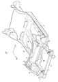
- FIG. 1 is a perspective view of a lower part of a vehicle body provided with an energy absorbing structure according to the first embodiment of the present invention.
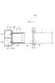
- FIG. 2 is a side view including a partial cross section around the energy absorbing structure of FIG.
- FIG. 3 is an exploded perspective view around the energy absorbing structure of FIG.
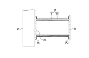
- FIG. 4 is a cross-sectional view in plan view showing a modification of the first embodiment.
- FIG. 5 is a cross-sectional view in plan view showing another modification of the first embodiment.
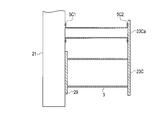
- FIG. 6 is a cross-sectional view in plan view showing a second embodiment of the present invention.
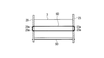
- FIG. 7 is a cross-sectional view in plan view showing a third embodiment of the present invention.
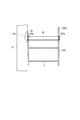
- FIG. 8 is a cross-sectional view in plan view showing a fourth embodiment of the present invention.
- FIG. 1 shows a lower part of a vehicle body to which an energy absorber 1 according to the first embodiment of the present invention is applied.
- the direction indicated by the arrow FR is the front side of the vehicle body
- the direction indicated by the arrow LH is the left side of the vehicle body
- the direction indicated by the arrow UP is the upper side of the vehicle body.
- the energy absorber 1 includes an energy absorbing member 3 inside, and a connecting member 5 is disposed so as to cover the outside of the energy absorbing member 3.
- the energy absorbing member 3 is a fiber reinforced resin material configured by impregnating a matrix resin that is a resin for impregnation into carbon fibers that are reinforcing fibers.
- the connecting member 5 is made of a non-brittle metal such as iron or aluminum. Each of the energy absorbing member 3 and the connecting member 5 has a quadrangular cylindrical shape.
- the front side member 7 constitutes a vehicle body skeleton member that forms the skeleton of the vehicle body, bends downward near a position corresponding to the dash panel 9, and is joined to the lower surface of the floor panel 11.
- the dash panel 9 separates the vehicle compartment 13 and the engine compartment 15.
- Side sills 17 are disposed along the vehicle longitudinal direction on both sides of the floor panel 11 in the vehicle width direction, and a hood ridge panel 19 is disposed on the upper side of the front side member 7 on the engine room 15 side.
- the energy absorber 1 is attached to the front end portion of the front side member 7.
- a bumper reinforcement 21 is attached to the front end of the energy absorber 1 opposite to the front side member 7.
- the bumper reinforcement 21 is disposed along the vehicle width direction, and both ends protrude outward in the vehicle width direction from the energy absorber 1.
- the bumper reinforcement 21 is a hollow member whose cross-sectional shape is long in the vertical direction.
- the bumper reinforcement 21 has a partition wall 21a at the center in the vertical direction, and a space having a substantially square cross section is formed above and below the partition wall 21a. It is formed.
- a bumper fascia (not shown) is attached to the bumper reinforcement 21 to constitute a bumper member.
- the front side member 7 is formed in a quadrangular cylindrical shape, and includes a front end flange 7a at the front end portion on the energy absorber 1 side as shown in FIG.
- a rear end attachment plate 23 is attached to the rear end of the energy absorber 1.
- the rear end mounting plate 23 is bonded and fixed to the rear end of the connecting member 5 by welding, for example.
- the front end member 7 and the connecting member 5 are connected and fixed by abutting the front end flange 7 a and the rear end mounting plate 23 with each other and fastening them with a plurality of bolts 25 and nuts 27.
- a front end mounting plate 29 is attached to the front end of the energy absorber 1.
- the front end mounting plate 29 is bonded and fixed to the front end of the connecting member 5 by welding, for example.
- Four stud bolts 31 projecting toward the bumper reinforcement 21 are provided on the front surface of the front end mounting plate 29.
- four bolt insertion holes 21 b are provided on the rear surface of the bumper reinforcement 21.
- the stud bolt 31 is inserted into the bolt insertion hole 21b, and the nut 33 is fastened to the stud bolt 31 using the front work hole 21c, so that the bumper reinforcement 21 and the connecting member 5 are connected and fixed.
- the front end and the rear end of the energy absorbing member 3 arranged inside the connecting member 5 are brought into contact with the front end mounting plate 29 and the rear end mounting plate 23, respectively, and are fixed with an adhesive, for example. At this time, a slight gap is formed over the entire circumference between the outer surface of the energy absorbing member 3 and the inner surface of the connecting member 5. You may attach so that the connection member 5 and the energy absorption member 3 may mutually contact
- the impact load received by the bumper reinforcement 21 when the vehicle collides front is transmitted to the front side member 7 via the energy absorber 1. At this time, the energy absorber 1 is deformed so as to be crushed between the bumper reinforcement 21 and the front side member 7 to absorb the impact.
- the energy absorbing member 3 absorbs the impact particularly by the deformation of the energy absorbing member 3.
- the resin portion is crushed and the fibers are separated.
- the metal connecting member 5 arranged outside the energy absorbing member 3 is plastically deformed when absorbing the impact.
- the connecting member 5 is plastically deformed by being crushed while maintaining the state of being connected and fixed to the bumper reinforcement 21 and the front side member 7 via the front end mounting plate 29 and the rear end mounting plate 23, respectively. For this reason, the bumper reinforcement 21 fixed to the front surface of the energy absorber 1 is separated from the vehicle body (front side member 7) together with the bumper fascia even when the energy absorber 3 is separated. Can be suppressed.
- the connecting member 5 covers the outside of the energy absorbing member 3. For this reason, scattering to the outside of the energy absorbing member 3 that has been separated can be suppressed.
- the connecting member 5 of the present embodiment transmits the impact load to the front side member 7 while being plastically deformed when the energy absorbing member 3 is broken by receiving the impact load from the bumper reinforcement 21.
- the impact load is transmitted to the front side member 7 while the connecting member 5 is plastically deformed even after the energy absorbing member 3 is separated. For this reason, load transmission from the bumper reinforcement 21 to the front side member 7 is more efficiently performed.
- the connecting member 5 of this embodiment is made of metal, and is joined and fixed to the rear end mounting plate 23 on the front side member 7 side and the front end mounting plate 29 on the bumper reinforcement 21 side by welding. Thereby, the connection state of the connection member 5, the front side member 7, and the bumper reinforcement 21 becomes stronger, and the falling off of the bumper reinforcement 21 can be more reliably suppressed.
- the cylindrical connecting member 5 is disposed outside the cylindrical energy absorbing member 3.
- the cylindrical connecting member 5 is disposed inside the cylindrical energy absorbing member 3. You may arrange in.
- the energy absorbing member 3 and the connecting member 5 are both rectangular cylinders, but other cylindrical shapes such as a cylindrical cylinder may be used.
- the connecting member 5 may not be cylindrical, and for example, a single plate or a bar may be arranged outside or inside the energy absorbing member 3.
- the energy absorbing member 3 is divided into, for example, two half-cylindrical divided bodies.
- the connecting member 5 after fixing the front and rear ends of the connecting member 5 to the front end mounting plate 29 and the rear end mounting plate 23, respectively, the two half-cylindrical divided bodies are covered with the connecting member 5 from the outside, for example, Secure with adhesive.
- a cylindrical or plate-shaped connecting member 5A is arranged outside the cylindrical energy absorbing member 3 as the energy absorber 1A.
- the energy absorber 1A includes flanges 5A1 and 5A2 at which the connecting member 5A bends outward at both front and rear ends, and these flanges 5A1 and 5A2 are connected to the front end mounting plate 29 and the rear end mounting plate 23 by welding.
- a plate-shaped connecting member 5B is arranged inside the cylindrical energy absorbing member 3 as the energy absorber 1B.
- the energy absorber 1B includes flanges 5B1 and 5B2 in which the connecting member 5B bends inward at both front and rear ends, and these flanges 5B1 and 5B2 are connected to the front end mounting plate 29 and the rear end mounting plate 23 by welding.
- FIG. 6 shows a second embodiment of the present invention.
- the connecting member 5C is arranged at a position spaced from the energy absorbing member 3.
- the connecting member 5C has a cylindrical shape such as a square pole, and the front and rear flanges 5C1 and 5C2 that are bent outward are welded and fixed to the bumper reinforcement 21 and the rear end mounting plate 23C, respectively.
- the rear end mounting plate 23C includes an extension portion 23Ca that is extended so as to protrude with respect to a position corresponding to the front side member 7, and the rear end flange 5C2 is fixed to the extension portion 23Ca by welding.
- the connecting member 5C is fixedly connected to the bumper reinforcement 21 and the front side member 7 via the front end mounting plate 29 and the rear end mounting plate 23C, respectively.
- the plastic deformation is carried out by being crushed while maintaining the state. For this reason, even if the energy absorbing member 3 is separated, the bumper reinforcement 21 can be prevented from dropping from the vehicle body (front side member 7) together with the bumper fascia.
- the connecting member 5C does not have to be cylindrical, and may be plate-shaped or rod-shaped. Further, the rear end of the connecting member 5C may be connected to a vehicle body skeleton member other than the front side member 7 instead of being connected to the front side member 7 via the rear end mounting plate 23C.
- FIG. 7 shows a third embodiment of the present invention.
- the connecting member 5D is composed of a linear material having flexibility of a non-brittle material.
- the linear material having flexibility may be a string made of chemical fibers such as rayon, a metal wire called a so-called wire, a glass fiber wire, or the like.
- the connecting member 5D made of a linear material is connected by being inserted into and connected to connecting holes 29a and 23a formed in the front end mounting plate 29 and the rear end mounting plate 23, respectively.
- the connecting member 5D is arranged outside the cylindrical energy absorbing member 3 in FIG. 7, but may be arranged inside.
- the connecting member 5D when the energy absorbing member 3 undergoes crushing deformation, the connecting member 5D is connected to the bumper reinforcement 21 and the front side member 7 via the front end mounting plate 29 and the rear end mounting plate 23, respectively. Maintain the state. For this reason, even if the energy absorbing member 3 is separated, the bumper reinforcement 21 can be prevented from falling off the vehicle body (front side member 7) together with the bumper fascia by the connecting member 5D.
- connection member 5D is made of a flexible linear material made of a non-brittle material
- the connecting member is made of a metal cylinder, plate, or bar. In comparison, weight reduction can be achieved. Moreover, it can connect easily by inserting connection member 5D which consists of a linear material in connection hole 23a, 29a.
- FIG. 8 shows a fourth embodiment of the present invention.
- connection member 5E is composed of a linear material having flexibility of a non-brittle material, like the connecting member 5D of the third embodiment shown in FIG.
- the rear end of the connecting member 5E on the front side member 7 side is inserted into a connecting hole 23Da formed in the rear end mounting plate 23D and connected by tying.
- the rear end mounting plate 23 ⁇ / b> D includes an extension 23 ⁇ / b> Db that is extended so as to protrude from a position corresponding to the front side member 7.
- the front end of the connecting member 5E on the bumper reinforcement 21 side is connected by being inserted into a connecting hole 35a formed in the connecting plate 35 and tied.
- the connecting plate 35 is connected to the rear surface of the bumper reinforcement 21 by, for example, welding and fixing.
- An escape hole 21d for avoiding interference with the connecting member 5E is provided at a position corresponding to the connecting member 5E on the rear surface of the bumper reinforcement 21.
- the connecting member 5E is connected to the bumper reinforcement 21 and the front side member 7 via the connecting plate 35 and the rear end mounting plate 23D, respectively. Maintain state. For this reason, even if the energy absorbing member 3 is separated, the bumper reinforcement 21 can be prevented from dropping from the vehicle body (front side member 7) together with the bumper fascia.
- the rear end of the connecting member 5E is connected to a vehicle body skeleton member other than the front side member 7 instead of being connected to the front side member 7 via the rear end mounting plate 23D, similarly to the connecting member 5C of FIG.
- the structure which connects may be sufficient.
- the example in which the energy absorbing structure including the energy absorbing member 3 is provided in the front part of the vehicle body has been described. it can.
- a woven fabric made of rayon or glass fiber may be used. 4 and 5 may be connected and fixed to the front end mounting plate 29 and the rear end mounting plate 23 by rivets when made of aluminum.
- the present invention is applied to an energy absorbing structure using an energy absorbing member made of fiber reinforced resin.
Abstract
Description
5,5A,5B,5C,5D,5E 連結部材
7 フロントサイドメンバ(車体骨格部材)
21 バンパレインフォース(バンパ部材)
23a,23Da,29a,35a 連結孔
Claims (5)
- 車体前後方向に沿って配置される車体骨格部材と、
車体の端部に設けられるバンパ部材と、
前記車体骨格部材と前記バンパ部材との間に設けられ、繊維強化樹脂で構成されるエネルギ吸収部材と、
非脆性材料で構成され、前記車体骨格部材と前記バンパ部材とを連結する連結部材と、を有することを特徴とするエネルギ吸収構造。 - 前記連結部材は、前記エネルギ吸収部材の外側を覆っていることを特徴とする請求項1に記載のエネルギ吸収構造。
- 前記連結部材は、前記エネルギ吸収部材が前記バンパ部材から衝撃荷重を受けて破壊されるときに、塑性変形しながら前記車体骨格部材に衝撃荷重を伝達することを特徴とする請求項1または2に記載のエネルギ吸収構造。
- 前記連結部材は、金属製であって、前記車体骨格部材及び前記バンパ部材に接合固定されていることを特徴とする請求項1ないし3のいずれか1項に記載のエネルギ吸収構造。
- 前記連結部材は、可撓性を有する線状材であり、前記車体骨格部材及び前記バンパ部材に設けられた連結孔に挿入されて連結されていることを特徴とする請求項1に記載のエネルギ吸収構造。
Priority Applications (5)
| Application Number | Priority Date | Filing Date | Title |
|---|---|---|---|
| JP2018512733A JPWO2017183173A1 (ja) | 2016-04-22 | 2016-04-22 | エネルギ吸収構造 |
| PCT/JP2016/062720 WO2017183173A1 (ja) | 2016-04-22 | 2016-04-22 | エネルギ吸収構造 |
| US16/094,894 US20190126869A1 (en) | 2016-04-22 | 2016-04-22 | Energy absorbing structure |
| CN201680084847.XA CN109070821A (zh) | 2016-04-22 | 2016-04-22 | 能量吸收结构 |
| EP16899445.7A EP3446929A1 (en) | 2016-04-22 | 2016-04-22 | Energy absorbing structure |
Applications Claiming Priority (1)
| Application Number | Priority Date | Filing Date | Title |
|---|---|---|---|
| PCT/JP2016/062720 WO2017183173A1 (ja) | 2016-04-22 | 2016-04-22 | エネルギ吸収構造 |
Publications (1)
| Publication Number | Publication Date |
|---|---|
| WO2017183173A1 true WO2017183173A1 (ja) | 2017-10-26 |
Family
ID=60116844
Family Applications (1)
| Application Number | Title | Priority Date | Filing Date |
|---|---|---|---|
| PCT/JP2016/062720 WO2017183173A1 (ja) | 2016-04-22 | 2016-04-22 | エネルギ吸収構造 |
Country Status (5)
| Country | Link |
|---|---|
| US (1) | US20190126869A1 (ja) |
| EP (1) | EP3446929A1 (ja) |
| JP (1) | JPWO2017183173A1 (ja) |
| CN (1) | CN109070821A (ja) |
| WO (1) | WO2017183173A1 (ja) |
Cited By (2)
| Publication number | Priority date | Publication date | Assignee | Title |
|---|---|---|---|---|
| JP2019142298A (ja) * | 2018-02-19 | 2019-08-29 | トヨタ自動車株式会社 | 車両前部構造とその生産方法 |
| WO2023120416A1 (ja) * | 2021-12-24 | 2023-06-29 | 帝人株式会社 | 衝撃吸収構造体 |
Families Citing this family (1)
| Publication number | Priority date | Publication date | Assignee | Title |
|---|---|---|---|---|
| GB2585012B (en) * | 2019-06-24 | 2021-11-17 | Jaguar Land Rover Ltd | Securing method for composite structure post-crash |
Citations (2)
| Publication number | Priority date | Publication date | Assignee | Title |
|---|---|---|---|---|
| JP2008254659A (ja) * | 2007-04-06 | 2008-10-23 | Toyota Motor Corp | バンパ取付け構造 |
| JP2015067006A (ja) * | 2013-09-26 | 2015-04-13 | 富士重工業株式会社 | 衝撃吸収構造 |
Family Cites Families (20)
| Publication number | Priority date | Publication date | Assignee | Title |
|---|---|---|---|---|
| US5150935A (en) * | 1990-11-06 | 1992-09-29 | Concept Analysis Corp. | Elastomeric energy absorbing mechanism for vehicle bumpers |
| JP3456596B2 (ja) * | 1994-02-08 | 2003-10-14 | 東レ株式会社 | エネルギー吸収部材 |
| JP2003056617A (ja) * | 2001-08-20 | 2003-02-26 | Nissan Motor Co Ltd | 衝撃エネルギ吸収構造部材 |
| EP1628857B1 (en) * | 2003-06-03 | 2010-01-27 | Decoma International Inc. | Bumper energy absorber and method of fabricating and assembling the same |
| JP4723942B2 (ja) * | 2004-09-28 | 2011-07-13 | アイシン精機株式会社 | 車両の衝撃吸収具及び車両の衝撃吸収構造 |
| DE102006058604B4 (de) * | 2006-12-11 | 2008-11-27 | Benteler Automobiltechnik Gmbh | Crashbox |
| KR101022784B1 (ko) * | 2009-08-19 | 2011-03-17 | 한국과학기술원 | 길이 가변형 차량용 충격 흡수 장치 |
| US8336933B2 (en) * | 2010-11-04 | 2012-12-25 | Sabic Innovative Plastics Ip B.V. | Energy absorbing device and methods of making and using the same |
| DE102011011816A1 (de) * | 2011-02-19 | 2012-08-23 | Daimler Ag | Energieabsorptionselement für einen Kraftwagen |
| JP2013231484A (ja) * | 2012-05-01 | 2013-11-14 | Toyota Auto Body Co Ltd | 衝撃吸収機構 |
| DE102013000269B4 (de) * | 2013-01-10 | 2017-09-14 | Benteler Automobiltechnik Gmbh | Stoßfängersystem für ein Kraftfahrzeug |
| US9067550B2 (en) * | 2013-01-18 | 2015-06-30 | Sabic Global Technologies B.V. | Polymer, energy absorber rail extension, methods of making and vehicles using the same |
| FR3009358A1 (fr) * | 2013-08-02 | 2015-02-06 | Alstom Transport Sa | Dispositif d'absorption d'energie de choc |
| US8939480B1 (en) * | 2013-08-15 | 2015-01-27 | Ford Global Technologies, Llc | Energy absorbing apparatus for a bumper rail |
| JP5791676B2 (ja) * | 2013-09-10 | 2015-10-07 | 富士重工業株式会社 | 衝撃吸収装置 |
| JP2015174612A (ja) * | 2014-03-18 | 2015-10-05 | 富士重工業株式会社 | 衝撃吸収装置 |
| FR3019785B1 (fr) * | 2014-04-09 | 2016-05-13 | Faurecia Bloc Avant | Poutre de pare-chocs de vehicule, ensemble pare-chocs et vehicule associes |
| US9168883B1 (en) * | 2014-09-03 | 2015-10-27 | Ford Global Technologies, Llc | Rail assembly for a frame of a vehicle |
| CN104590178A (zh) * | 2014-12-24 | 2015-05-06 | 芜湖市汽车产业技术研究院有限公司 | 一种汽车吸能盒 |
| JP6913029B2 (ja) * | 2015-12-24 | 2021-08-04 | 株式会社Uacj | エネルギー吸収部材 |
-
2016
- 2016-04-22 US US16/094,894 patent/US20190126869A1/en not_active Abandoned
- 2016-04-22 WO PCT/JP2016/062720 patent/WO2017183173A1/ja active Application Filing
- 2016-04-22 EP EP16899445.7A patent/EP3446929A1/en not_active Withdrawn
- 2016-04-22 JP JP2018512733A patent/JPWO2017183173A1/ja active Pending
- 2016-04-22 CN CN201680084847.XA patent/CN109070821A/zh active Pending
Patent Citations (2)
| Publication number | Priority date | Publication date | Assignee | Title |
|---|---|---|---|---|
| JP2008254659A (ja) * | 2007-04-06 | 2008-10-23 | Toyota Motor Corp | バンパ取付け構造 |
| JP2015067006A (ja) * | 2013-09-26 | 2015-04-13 | 富士重工業株式会社 | 衝撃吸収構造 |
Non-Patent Citations (1)
| Title |
|---|
| See also references of EP3446929A4 * |
Cited By (3)
| Publication number | Priority date | Publication date | Assignee | Title |
|---|---|---|---|---|
| JP2019142298A (ja) * | 2018-02-19 | 2019-08-29 | トヨタ自動車株式会社 | 車両前部構造とその生産方法 |
| JP7031356B2 (ja) | 2018-02-19 | 2022-03-08 | トヨタ自動車株式会社 | 車両前部構造 |
| WO2023120416A1 (ja) * | 2021-12-24 | 2023-06-29 | 帝人株式会社 | 衝撃吸収構造体 |
Also Published As
| Publication number | Publication date |
|---|---|
| JPWO2017183173A1 (ja) | 2019-04-04 |
| EP3446929A4 (en) | 2019-02-27 |
| CN109070821A (zh) | 2018-12-21 |
| US20190126869A1 (en) | 2019-05-02 |
| EP3446929A1 (en) | 2019-02-27 |
Similar Documents
| Publication | Publication Date | Title |
|---|---|---|
| JP4525802B2 (ja) | 車両骨格構造 | |
| JP5915622B2 (ja) | サスペンションタワー及び車両前部構造 | |
| US20130249245A1 (en) | Front vehicle body structure | |
| CN110171477B (zh) | 车身结构 | |
| KR101046170B1 (ko) | 차량용 크래쉬 박스 | |
| WO2017183173A1 (ja) | エネルギ吸収構造 | |
| JP4797704B2 (ja) | 車体前部構造 | |
| JP5236916B2 (ja) | 車両用バンパ装置 | |
| JP4853147B2 (ja) | 自動車のバンパ構造 | |
| JP4529997B2 (ja) | 車体前部構造 | |
| CN107953846B (zh) | 保险杠强化部与纵梁的联结结构 | |
| JP6879174B2 (ja) | 前部車体構造 | |
| EP3659871B1 (en) | Vehicle front structure | |
| JP6228623B2 (ja) | 車両用バンパ構造 | |
| KR101374737B1 (ko) | 차량용 도어 충격 흡수부재 | |
| JP2007230489A (ja) | 車体前部構造 | |
| JP4589543B2 (ja) | バンパ取付構造 | |
| JP6191469B2 (ja) | 車体の部材締結構造 | |
| JP2007008346A (ja) | 車両後部構造 | |
| JP5668583B2 (ja) | 車体下部構造 | |
| JP2015193282A (ja) | 車両用バンパー装置の補強部材 | |
| JP2008068760A (ja) | 車体前部構造 | |
| JP6566018B2 (ja) | 車両の衝撃吸収構造 | |
| CN113613959B (zh) | 冲击能量吸收部件 | |
| JP2010173423A (ja) | ストライカ取付構造 |
Legal Events
| Date | Code | Title | Description |
|---|---|---|---|
| ENP | Entry into the national phase |
Ref document number: 2018512733 Country of ref document: JP Kind code of ref document: A |
|
| NENP | Non-entry into the national phase |
Ref country code: DE |
|
| WWE | Wipo information: entry into national phase |
Ref document number: 2016899445 Country of ref document: EP |
|
| ENP | Entry into the national phase |
Ref document number: 2016899445 Country of ref document: EP Effective date: 20181122 |
|
| 121 | Ep: the epo has been informed by wipo that ep was designated in this application |
Ref document number: 16899445 Country of ref document: EP Kind code of ref document: A1 |