EP3659871B1 - Vehicle front structure - Google Patents
Vehicle front structure Download PDFInfo
- Publication number
- EP3659871B1 EP3659871B1 EP19211694.5A EP19211694A EP3659871B1 EP 3659871 B1 EP3659871 B1 EP 3659871B1 EP 19211694 A EP19211694 A EP 19211694A EP 3659871 B1 EP3659871 B1 EP 3659871B1
- Authority
- EP
- European Patent Office
- Prior art keywords
- stay
- grille
- bumper
- cover
- disposed
- Prior art date
- Legal status (The legal status is an assumption and is not a legal conclusion. Google has not performed a legal analysis and makes no representation as to the accuracy of the status listed.)
- Active
Links
- 230000002787 reinforcement Effects 0.000 description 24
- 239000006096 absorbing agent Substances 0.000 description 13
- 230000035939 shock Effects 0.000 description 13
- 210000002414 leg Anatomy 0.000 description 9
- 238000010586 diagram Methods 0.000 description 3
- 210000003041 ligament Anatomy 0.000 description 3
- 210000000689 upper leg Anatomy 0.000 description 3
- 229910000831 Steel Inorganic materials 0.000 description 2
- 230000000052 comparative effect Effects 0.000 description 2
- 210000003127 knee Anatomy 0.000 description 2
- 239000010959 steel Substances 0.000 description 2
- 239000011358 absorbing material Substances 0.000 description 1
- 238000005452 bending Methods 0.000 description 1
- 239000000498 cooling water Substances 0.000 description 1
- 239000000463 material Substances 0.000 description 1
- 230000002093 peripheral effect Effects 0.000 description 1
- 239000003507 refrigerant Substances 0.000 description 1
- 239000011347 resin Substances 0.000 description 1
- 229920005989 resin Polymers 0.000 description 1
- 238000000926 separation method Methods 0.000 description 1
Images


Classifications
-
- B—PERFORMING OPERATIONS; TRANSPORTING
- B60—VEHICLES IN GENERAL
- B60R—VEHICLES, VEHICLE FITTINGS, OR VEHICLE PARTS, NOT OTHERWISE PROVIDED FOR
- B60R19/00—Wheel guards; Radiator guards, e.g. grilles; Obstruction removers; Fittings damping bouncing force in collisions
- B60R19/02—Bumpers, i.e. impact receiving or absorbing members for protecting vehicles or fending off blows from other vehicles or objects
- B60R19/04—Bumpers, i.e. impact receiving or absorbing members for protecting vehicles or fending off blows from other vehicles or objects formed from more than one section in a side-by-side arrangement
- B60R19/12—Bumpers, i.e. impact receiving or absorbing members for protecting vehicles or fending off blows from other vehicles or objects formed from more than one section in a side-by-side arrangement vertically spaced
-
- B—PERFORMING OPERATIONS; TRANSPORTING
- B60—VEHICLES IN GENERAL
- B60R—VEHICLES, VEHICLE FITTINGS, OR VEHICLE PARTS, NOT OTHERWISE PROVIDED FOR
- B60R21/00—Arrangements or fittings on vehicles for protecting or preventing injuries to occupants or pedestrians in case of accidents or other traffic risks
- B60R21/34—Protecting non-occupants of a vehicle, e.g. pedestrians
-
- B—PERFORMING OPERATIONS; TRANSPORTING
- B60—VEHICLES IN GENERAL
- B60R—VEHICLES, VEHICLE FITTINGS, OR VEHICLE PARTS, NOT OTHERWISE PROVIDED FOR
- B60R19/00—Wheel guards; Radiator guards, e.g. grilles; Obstruction removers; Fittings damping bouncing force in collisions
- B60R19/02—Bumpers, i.e. impact receiving or absorbing members for protecting vehicles or fending off blows from other vehicles or objects
- B60R19/18—Bumpers, i.e. impact receiving or absorbing members for protecting vehicles or fending off blows from other vehicles or objects characterised by the cross-section; Means within the bumper to absorb impact
-
- B—PERFORMING OPERATIONS; TRANSPORTING
- B60—VEHICLES IN GENERAL
- B60R—VEHICLES, VEHICLE FITTINGS, OR VEHICLE PARTS, NOT OTHERWISE PROVIDED FOR
- B60R19/00—Wheel guards; Radiator guards, e.g. grilles; Obstruction removers; Fittings damping bouncing force in collisions
- B60R19/02—Bumpers, i.e. impact receiving or absorbing members for protecting vehicles or fending off blows from other vehicles or objects
- B60R19/24—Arrangements for mounting bumpers on vehicles
- B60R19/26—Arrangements for mounting bumpers on vehicles comprising yieldable mounting means
- B60R19/34—Arrangements for mounting bumpers on vehicles comprising yieldable mounting means destroyed upon impact, e.g. one-shot type
-
- B—PERFORMING OPERATIONS; TRANSPORTING
- B60—VEHICLES IN GENERAL
- B60R—VEHICLES, VEHICLE FITTINGS, OR VEHICLE PARTS, NOT OTHERWISE PROVIDED FOR
- B60R19/00—Wheel guards; Radiator guards, e.g. grilles; Obstruction removers; Fittings damping bouncing force in collisions
- B60R19/52—Radiator or grille guards ; Radiator grilles
-
- B—PERFORMING OPERATIONS; TRANSPORTING
- B62—LAND VEHICLES FOR TRAVELLING OTHERWISE THAN ON RAILS
- B62D—MOTOR VEHICLES; TRAILERS
- B62D25/00—Superstructure or monocoque structure sub-units; Parts or details thereof not otherwise provided for
- B62D25/08—Front or rear portions
- B62D25/082—Engine compartments
- B62D25/084—Radiator supports
-
- B—PERFORMING OPERATIONS; TRANSPORTING
- B60—VEHICLES IN GENERAL
- B60R—VEHICLES, VEHICLE FITTINGS, OR VEHICLE PARTS, NOT OTHERWISE PROVIDED FOR
- B60R19/00—Wheel guards; Radiator guards, e.g. grilles; Obstruction removers; Fittings damping bouncing force in collisions
- B60R19/02—Bumpers, i.e. impact receiving or absorbing members for protecting vehicles or fending off blows from other vehicles or objects
- B60R19/18—Bumpers, i.e. impact receiving or absorbing members for protecting vehicles or fending off blows from other vehicles or objects characterised by the cross-section; Means within the bumper to absorb impact
- B60R2019/1886—Bumper fascias and fastening means therefor
-
- B—PERFORMING OPERATIONS; TRANSPORTING
- B60—VEHICLES IN GENERAL
- B60R—VEHICLES, VEHICLE FITTINGS, OR VEHICLE PARTS, NOT OTHERWISE PROVIDED FOR
- B60R19/00—Wheel guards; Radiator guards, e.g. grilles; Obstruction removers; Fittings damping bouncing force in collisions
- B60R19/52—Radiator or grille guards ; Radiator grilles
- B60R2019/525—Radiator grilles
- B60R2019/527—Radiator grilles integral with bumpers
-
- B—PERFORMING OPERATIONS; TRANSPORTING
- B60—VEHICLES IN GENERAL
- B60R—VEHICLES, VEHICLE FITTINGS, OR VEHICLE PARTS, NOT OTHERWISE PROVIDED FOR
- B60R21/00—Arrangements or fittings on vehicles for protecting or preventing injuries to occupants or pedestrians in case of accidents or other traffic risks
- B60R21/34—Protecting non-occupants of a vehicle, e.g. pedestrians
- B60R2021/343—Protecting non-occupants of a vehicle, e.g. pedestrians using deformable body panel, bodywork or components
Definitions
- the present disclosure relates to a vehicle front structure including a grille stay disposed behind a bumper panel.
- Patent Document 1 discloses a front bumper including an upper bumper portion and a lower bumper portion, and impact absorbing members disposed in the respective portions.
- the strength of the lower absorbing material disposed in the lower bumper portion against impact is greater than that of the upper absorbing member disposed in the upper bumper portion.
- Patent Document 1 JP 2001-277964 A
- Patent Document 1 assumes vehicles having an inclined front portion with a front end having a rather small height. However, some vehicles have a rather large front grille, and a front end with a greater height. When a vehicle with such a front end shape collides with a pedestrian, the load applied to the pedestrian's leg would differ from that applied by the assumed vehicle described above. Therefore, there is a demand that the load applied to the pedestrian's leg in collision should be appropriately varied in accordance with the shape of the vehicle.
- WO 95/02525 A1 discloses a vehicle front structure according to the preamble of claim 1.
- DE 10 2009 030686 A1 discloses another vehicle front structure.
- a vehicle front structure includes a grille stay located behind a bumper panel having a grille opening, and a stay cover disposed to cover a rear portion of the grille stay.
- the grill stay faces an upper portion of the bumper panel from behind.
- the grille stay includes a front portion and a rear portion and the rear portion has a smaller cross sectional area than the front portion.
- the grill stay further includes a step portion at a boundary between the front portion and the rear portion.
- the stay cover includes a front end that is disposed to face a rear face of the step portion.
- a radiator support is disposed behind the bumper panel, and a duct upper wall extends from an upper portion of the radiator support toward the bumper panel above the grille opening.
- the duct upper wall has a front end facing an abutting surface extending rearward on a rear surface of the bumper panel.
- the stay cover may be secured to the radiator support via a grille bracket, and the stay cover, the duct upper wall, and the grille bracket may be fastened and secured together.
- the grille stay may have a box shape.
- the vehicle front structure of the disclosure increases a resisting force against impact in the upper portion of the vehicle front face, thereby allowing an appropriate load to be applied to the pedestrian's leg in a collision.
- FIG. 1 illustrates a vehicle front structure and shows principal elements in the embodiment.
- the vehicle front structure includes a bumper panel 10 having an entirely rectangular shape and forming a front face of a vehicle.
- the bumper panel 10 includes a comparatively large lower grille opening 12 and a comparatively small upper grille opening 14, through which air enters a front space (engine compartment).
- the front vehicle structure further includes, below the lower grille opening 12, a lower bumper 16, and includes an upper bumper 18 between the lower grille opening 12 and the upper grille opening 14.
- the vehicle front structure further includes, behind the lower bumper 16, a lower shock absorber 20 formed of an impact absorbing member, and a lower bumper reinforcement 24 behind the lower shock absorber 20.
- the lower bumper reinforcement 24 is a rectangular pipe-like frame member made of a steel member, for example, and extends along the vehicle width.
- the vehicle front structure further includes, behind the upper bumper 18, an upper shock absorber 22 formed of an impact absorbing member, and includes, behind the upper shock absorber 22, an upper bumper reinforcement 26.
- the upper bumper reinforcement 26 is also a rectangular pipe-like frame member extending along the vehicle width.
- a lower end of the lower bumper 16 is connected to a front end of an under cover 28.
- the under cover 28 extends rearward from the lower bumper 16 to cover the lower part of the front portion of the engine compartment.
- a lower wall 30a of a four-direction duct 30 extending rearward is disposed,
- the bumper panel 10 has an upper end which is connected with a body front end 32, on which a front end of a front hood 34 is disposed.
- the front hood 34 is openable with respect to the body front end 32.
- a radiator support 40 is disposed behind the bumper panel 10, and a condenser 42 and a radiator 44 are further disposed behind the radiator support 40.
- the condenser 42 cools a refrigerant of an air conditioner, and the radiator 44 cools cooling water for the engine.
- the radiator support 40 has a rectangular frame shape as a whole, and includes a center support 40a near the center in the vehicle width direction, extending along the vehicle height.
- the four-direction duct 30 guides air entering through the lower grille opening 12 and the upper grille opening 14 to the radiator 44, and includes walls in four directions.
- the lower wall 30a forms a top surface of the lower shock absorber 20.
- a duct upper wall 30b of the four-direction duct 30 is disposed behind the bumper panel 10 and above the upper shock absorber 22.
- the vehicle front structure further includes, on the duct upper wall 30b, a grille stay 50 and also includes a stay cover 52 covering a rear portion of the grille stay 50.
- the stay cover 52 and the duct upper wall 30b are fastened and secured together with a grille bracket 54 disposed below, and a rear end of the grille bracket 54 is secured to the radiator support 40.
- Frame members including the lower bumper reinforcement 24, the upper bumper reinforcement 26, and the radiator support 40, and bodies including the body front end 32 and the front hood 34 may be composed of a steel material, while other members may be composed of resin.
- FIG. 2 illustrates a structure of the grille stay 50.
- the grille stay 50 includes a front portion 502 having a forwardly increasing cross sectional area, with a front face 504 being positioned along a rear face of the bumper panel 10.
- the front portion 502 has a box shape having a hollow interior.
- the grille stay 50 further includes a rear portion 506 having a rectangular parallelepiped shape and having a cross sectional area smaller than that of the front portion 502.
- a step portion 508 is formed between the front portion 502 and the rear portion 506.
- the front portion 502 includes, on its undersurface, a plurality of fins 510 to enhance the strength of the grille stay 50 along the length of the vehicle.
- FIG. 3 illustrates a structure of the stay cover 52.
- the stay cover 52 includes a cover body 522 having a rectangular tube shape as a whole, and includes, on its top surface, a slit 524 formed from rearward.
- the stay cover 52 further includes two bolt shafts 528 extending downward from its undersurface.
- the stay cover 52 also includes, on a front end of the cover body 522, a flange portion 526 expanding toward the peripheral portion.
- the stay cover 52 may house the rear portion 506 of the grille stay 50 therein, and the front face of the flange portion 526 abuts against the rear face of the step portion 508 of the grille stay 50.
- FIG. 4 illustrates a structure of the grille bracket 54.
- the grille bracket 54 includes a bracket body 542 having an inverted and upside-down L shape and including an upper piece 542a and a side piece 542b.
- the side piece 542b extends further rearward than the upper piece 542a, and a flange portion 544 is disposed on the rear end of the side piece 542b.
- the flange portion 544 is formed to extend laterally and upward.
- the upper piece 542a includes a hole (not shown) through which the bolt shaft 528 of the stay cover 52 passes.
- FIG. 5 illustrates a securing structure for the grille stay 50.
- the rear portion 506 of the grille stay 50 is housed in the cover body 522 of the stay cover 52.
- the rear face of the step portion 508 of the grille stay 50 laps with the flange portion 526 of the stay cover 52 in the vehicle length direction so that they face each other.
- the bolt shafts 528 pass through the duct upper wall 30b and the upper piece 542a of the grille bracket 54, and nuts 530 are screwed in the tips of the bolt shafts 528.
- the stay cover 52 and the grille bracket 54 are fastened and secured together, with the duct upper wall 30b being disposed between them.
- the flange portion 544 on the rear end of the grille bracket 54 is secured to a bracket 46 extending from the radiator support 40.
- the other end of the bracket 46 may be secured to the center support 40a of the radiator support 40 or to an upper support 40d extending along the vehicle width.
- FIG. 6 illustrates a structure of a securing portion securing the stay cover 52 and the grille bracket 54.
- the bolt shaft 528 passes through the duct upper wall 30b and the upper piece 542a of the grille bracket 54, and the nut 530 is screwed in the tip end of the bolt shaft 528.
- the duct upper wall 30b has a leading end 30e that faces an abutting surface 10b of a rear protruding portion disposed on a rear surface member 10a on the rear surface of the bumper panel 10. Therefore, when the bumper panel 10 deforms rearward, the leading end 30e of the duct upper wall 30b hits the abutting surface 10b.
- FIG. 7 illustrates the radiator support 40 as viewed from forward.
- the radiator support 40 includes, in addition to the center support 40a extending vertically in the center in the vehicle width direction, the upper support 40d extending in the upper portion along the vehicle width, side supports 40b and 40c extending vertically at the respective sides, and a lower support 40e, to form a rectangular frame shape as a whole.
- the radiator support 40 further includes, outward of the side supports 40b and 40c, support poles 48a and 48b, respectively, extending vertically to connect opposite ends of the upper support 40d with opposite ends of the lower support 40e.
- the vertical strength of the radiator support 40 may be obtained by these support poles 48a and 48b; the side supports 40b and 40c may function as members for mounting other components. Front ends of side members, which are vehicle frame members extending from rearward, are attached to the support poles 48a and 48b, respectively, from rearward.
- FIG. 8 illustrates the radiator support 40 with the lower bumper reinforcement 24 and the upper bumper reinforcement 26 attached on its front portion.
- support members 60 extending forward are disposed on the lower parts of the pole 48a and 48b, respectively, with opposite ends of the lower bumper reinforcement 24 being secured to the leading ends of the support members 60, respectively.
- Support members 62 extending forward are further disposed on the upper parts of the support poles 48a and 48b, respectively, with opposite ends of the upper bumper reinforcement 26 being secured to the leading ends of the support members 62, respectively.
- the lower shock absorber 20 is disposed to cover the front face of the lower bumper reinforcement 24, and the upper shock absorber 22 is disposed to cover the front face of the upper bumper reinforcement 26.
- the duct upper wall 30b and side walls 30c and 30d are disposed in front of the upper support 40d and the side supports 40b and 40c of the radiator support 40, respectively.
- FIG. 9 illustrates a state where the support pole 48, and the lower bumper reinforcement 24 and the upper bumper reinforcement 26 are mounted. As illustrated, the support members 60 and 62 are disposed in front of the support pole 48, the lower bumper reinforcement 24 and the upper bumper reinforcement 26 are attached to the respective leading ends of the support members 60 and 62, and the lower shock absorber 20 and the upper shock absorber 22 are disposed in front of the lower bumper reinforcement 24 and the upper bumper reinforcement 26.
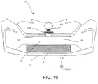
- FIG. 10 illustrates the bumper panel 10 as viewed from frontward.
- the bumper panel 10 is a rectangular panel extending along the vehicle width as a whole, with opposite side portions and an upper portion extending rearward.
- the grille stay 50 is located on the rear surface of the bumper panel 10 near its center top portion, and the abutting surface 10b is located below the grille stay 50.
- FIG. 10 schematically shows these members.
- FIG. 1 illustrates deformation of the vehicle front portion and a leg 70 upon impact in a dashed line.
- the pedestrian's leg 70 includes a shin portion 70a and a thigh portion 70b with a ligament 70c located at a knee portion.
- the lower shock absorber 20 and the upper shock absorber 22 of the vehicle front portion resist the impact.
- the grille stay 50 having a box shape is disposed above the upper shock absorber 22 on the rear side of the bumper panel 10. Therefore, when the upper portion of the bumper panel 10 moves rearward, the rear surface of the bumper panel 10 hits the grille stay 50.
- the stay cover 52 is secured to the radiator support 40 by the grille bracket 54.
- the stay cover 52 includes a front end facing the rear face of the step portion of the grille stay 50.
- the duct upper wall 30b is further secured to the radiator support 40 by the grille bracket 54. Therefore, when the bumper panel 10 attempts to move rearward, the abutting surface 10b hits the leading end 30e of the duct upper wall 30b to thereby reduce the amount of rearward movement of the bumper panel 10.
- the under cover 28 is temporarily bent downward toward the rear portion, and is thereafter bent upward.
- This upward bent portion serves as a ridge 28a extending along the vehicle width. Therefore, when the lower bumper 16 moves rearward, the under cover 28 bends upward about the ridge 28a in a region before the ridge 28a to form an upward convex.
- the lower bumper reinforcement 24 is located at a position corresponding to an apex of the upward convex, to thereby reduce further bending of the under cover 28 and increase the force that resists the rearward movement of the lower bumper 16.
- the ridge portion 28a may be reinforced to assist the deformation about the ridge 28a.
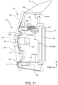
- FIG. 11 illustrates a comparative example structure including a grille stay 50 having a plate shape, with the stay cover 52 and the abutting surface 10b being omitted.
- FIG. 11 also shows a shape of the leg 70 after deformation in a dashed line.
- This structure provides only a small force that supports the bumper panel 10 in the portion above the upper bumper 18, and also provides a small resisting force against separation between the thigh portion 70b and the shin portion 70a.
- the fastening portion of the grille stay 50 breaks or bends upward, so that the bumper panel 10 moves significantly rearward.
- the under cover 28, which is bent upward has no obstacles above, an amount of rearward movement is increased in the lower portion of the bumper panel.
- the force in the direction of expanding the pedestrian's ligament 70c increases.
- the vehicle according to the present embodiment includes a front face extending approximately in the vertical direction and having a great height, the front face of the vehicle hits the whole leg 70 upon impact.
- the front face cannot therefore provide rotation to cause the pedestrian's leg 70 to move forward and upward.
- the bumper panel 10 may have a certain degree of resisting force in the upper portion to suppress rearward intrusion of the thigh portion 70b and thereby reduce a tensile force for the ligament 70c.
Description
- The present disclosure relates to a vehicle front structure including a grille stay disposed behind a bumper panel.
- Patent Document 1 discloses a front bumper including an upper bumper portion and a lower bumper portion, and impact absorbing members disposed in the respective portions. The strength of the lower absorbing material disposed in the lower bumper portion against impact is greater than that of the upper absorbing member disposed in the upper bumper portion. When the vehicle front portion collides with a pedestrian, this structure allows the lower bumper part to strongly push the shin part of the pedestrian to scoop it up, thereby reducing the impact applied to the knee of the pedestrian.
- Patent Document 1:
JP 2001-277964 A - Patent Document 1 assumes vehicles having an inclined front portion with a front end having a rather small height. However, some vehicles have a rather large front grille, and a front end with a greater height. When a vehicle with such a front end shape collides with a pedestrian, the load applied to the pedestrian's leg would differ from that applied by the assumed vehicle described above. Therefore, there is a demand that the load applied to the pedestrian's leg in collision should be appropriately varied in accordance with the shape of the vehicle.
-
WO 95/02525 A1 DE 10 2009 030686 A1 discloses another vehicle front structure. - A vehicle front structure according to the disclosure includes a grille stay located behind a bumper panel having a grille opening, and a stay cover disposed to cover a rear portion of the grille stay. The grill stay faces an upper portion of the bumper panel from behind. In the vehicle front structure, the grille stay includes a front portion and a rear portion and the rear portion has a smaller cross sectional area than the front portion. The grill stay further includes a step portion at a boundary between the front portion and the rear portion. The stay cover includes a front end that is disposed to face a rear face of the step portion.
- A radiator support is disposed behind the bumper panel, and a duct upper wall extends from an upper portion of the radiator support toward the bumper panel above the grille opening. The duct upper wall has a front end facing an abutting surface extending rearward on a rear surface of the bumper panel.
- The stay cover may be secured to the radiator support via a grille bracket, and the stay cover, the duct upper wall, and the grille bracket may be fastened and secured together.
- The grille stay may have a box shape.
- The vehicle front structure of the disclosure increases a resisting force against impact in the upper portion of the vehicle front face, thereby allowing an appropriate load to be applied to the pedestrian's leg in a collision.
- Embodiment(s) of the present disclosure will be described based on the following figures, wherein:
-
FIG. 1 illustrates a vehicle front structure; -
FIG. 2 illustrates a structure of a grille stay; -
FIG. 3 illustrates a structure of a stay cover; -
FIG. 4 illustrates a structure of a grille bracket; -
FIG. 5 illustrates a securing structure for the grille stay; -
FIG. 6 illustrates a structure of a securing portion for the stay cover and the grille bracket; -
FIG. 7 is a diagram illustrating the radiator support seen from frontward; -
FIG. 8 is a diagram illustrating a lower bumper reinforcement and an upper bumper reinforcement mounted before the radiator support; -
FIG. 9 is a diagram illustrating a support pole, the lower bumper reinforcement, and the upper bumper reinforcement, mounted on the radiator support; -
FIG. 10 illustrates a bumper panel seen from forward; -
FIG. 11 illustrates a comparative example structure including a grille stay in a plate shape with the stay cover and the abutting surface being omitted. - Embodiments of the present disclosure will be described by reference to the drawings. However, the disclosure is not limited to the embodiments described herein.
-
FIG. 1 illustrates a vehicle front structure and shows principal elements in the embodiment. - The vehicle front structure includes a
bumper panel 10 having an entirely rectangular shape and forming a front face of a vehicle. Thebumper panel 10 includes a comparatively large lower grille opening 12 and a comparatively small upper grille opening 14, through which air enters a front space (engine compartment). The front vehicle structure further includes, below the lower grille opening 12, alower bumper 16, and includes anupper bumper 18 between the lower grille opening 12 and the upper grille opening 14. - The vehicle front structure further includes, behind the
lower bumper 16, a lower shock absorber 20 formed of an impact absorbing member, and alower bumper reinforcement 24 behind the lower shock absorber 20. Thelower bumper reinforcement 24 is a rectangular pipe-like frame member made of a steel member, for example, and extends along the vehicle width. - The vehicle front structure further includes, behind the
upper bumper 18, an upper shock absorber 22 formed of an impact absorbing member, and includes, behind the upper shock absorber 22, anupper bumper reinforcement 26. Theupper bumper reinforcement 26 is also a rectangular pipe-like frame member extending along the vehicle width. - A lower end of the
lower bumper 16 is connected to a front end of an undercover 28. Theunder cover 28 extends rearward from thelower bumper 16 to cover the lower part of the front portion of the engine compartment. - Under the lower grille opening 12, a
lower wall 30a of a four-direction duct 30 extending rearward is disposed, - The
bumper panel 10 has an upper end which is connected with abody front end 32, on which a front end of afront hood 34 is disposed. Thefront hood 34 is openable with respect to thebody front end 32. - A
radiator support 40 is disposed behind thebumper panel 10, and acondenser 42 and aradiator 44 are further disposed behind theradiator support 40. Thecondenser 42 cools a refrigerant of an air conditioner, and theradiator 44 cools cooling water for the engine. Theradiator support 40 has a rectangular frame shape as a whole, and includes acenter support 40a near the center in the vehicle width direction, extending along the vehicle height. - The four-
direction duct 30 guides air entering through the lower grille opening 12 and the upper grille opening 14 to theradiator 44, and includes walls in four directions. In this example, thelower wall 30a forms a top surface of the lower shock absorber 20. - A duct
upper wall 30b of the four-direction duct 30 is disposed behind thebumper panel 10 and above the upper shock absorber 22. The vehicle front structure further includes, on the ductupper wall 30b, a grille stay 50 and also includes astay cover 52 covering a rear portion of the grille stay 50. Thestay cover 52 and the ductupper wall 30b are fastened and secured together with agrille bracket 54 disposed below, and a rear end of thegrille bracket 54 is secured to theradiator support 40. - Frame members including the
lower bumper reinforcement 24, theupper bumper reinforcement 26, and the radiator support 40, and bodies including thebody front end 32 and thefront hood 34 may be composed of a steel material, while other members may be composed of resin. -
FIG. 2 illustrates a structure of thegrille stay 50. The grille stay 50 includes afront portion 502 having a forwardly increasing cross sectional area, with afront face 504 being positioned along a rear face of thebumper panel 10. Thefront portion 502 has a box shape having a hollow interior. The grille stay 50 further includes arear portion 506 having a rectangular parallelepiped shape and having a cross sectional area smaller than that of thefront portion 502. Thus, astep portion 508 is formed between thefront portion 502 and therear portion 506. Thefront portion 502 includes, on its undersurface, a plurality offins 510 to enhance the strength of the grille stay 50 along the length of the vehicle. -
FIG. 3 illustrates a structure of thestay cover 52. Thestay cover 52 includes acover body 522 having a rectangular tube shape as a whole, and includes, on its top surface, aslit 524 formed from rearward. Thestay cover 52 further includes twobolt shafts 528 extending downward from its undersurface. Thestay cover 52 also includes, on a front end of thecover body 522, aflange portion 526 expanding toward the peripheral portion. Thestay cover 52 may house therear portion 506 of thegrille stay 50 therein, and the front face of theflange portion 526 abuts against the rear face of thestep portion 508 of thegrille stay 50. -
FIG. 4 illustrates a structure of thegrille bracket 54. Thegrille bracket 54 includes abracket body 542 having an inverted and upside-down L shape and including anupper piece 542a and aside piece 542b. Theside piece 542b extends further rearward than theupper piece 542a, and aflange portion 544 is disposed on the rear end of theside piece 542b. In this example, theflange portion 544 is formed to extend laterally and upward. Theupper piece 542a includes a hole (not shown) through which thebolt shaft 528 of thestay cover 52 passes. -
FIG. 5 illustrates a securing structure for thegrille stay 50. Therear portion 506 of thegrille stay 50 is housed in thecover body 522 of thestay cover 52. The rear face of thestep portion 508 of the grille stay 50 laps with theflange portion 526 of thestay cover 52 in the vehicle length direction so that they face each other. Thebolt shafts 528 pass through the ductupper wall 30b and theupper piece 542a of thegrille bracket 54, andnuts 530 are screwed in the tips of thebolt shafts 528. As such, thestay cover 52 and thegrille bracket 54 are fastened and secured together, with the ductupper wall 30b being disposed between them. Theflange portion 544 on the rear end of thegrille bracket 54 is secured to abracket 46 extending from theradiator support 40. The other end of thebracket 46 may be secured to thecenter support 40a of theradiator support 40 or to anupper support 40d extending along the vehicle width. -
FIG. 6 illustrates a structure of a securing portion securing thestay cover 52 and thegrille bracket 54. As illustrated, thebolt shaft 528 passes through the ductupper wall 30b and theupper piece 542a of thegrille bracket 54, and thenut 530 is screwed in the tip end of thebolt shaft 528. - Further, the duct
upper wall 30b has aleading end 30e that faces anabutting surface 10b of a rear protruding portion disposed on arear surface member 10a on the rear surface of thebumper panel 10. Therefore, when thebumper panel 10 deforms rearward, theleading end 30e of the ductupper wall 30b hits the abuttingsurface 10b. -
FIG. 7 illustrates theradiator support 40 as viewed from forward. As illustrated, theradiator support 40 includes, in addition to thecenter support 40a extending vertically in the center in the vehicle width direction, theupper support 40d extending in the upper portion along the vehicle width, side supports 40b and 40c extending vertically at the respective sides, and alower support 40e, to form a rectangular frame shape as a whole. Theradiator support 40 further includes, outward of the side supports 40b and 40c,support poles upper support 40d with opposite ends of thelower support 40e. The vertical strength of theradiator support 40 may be obtained by thesesupport poles support poles -
FIG. 8 illustrates theradiator support 40 with thelower bumper reinforcement 24 and theupper bumper reinforcement 26 attached on its front portion. As illustrated,support members 60 extending forward are disposed on the lower parts of thepole lower bumper reinforcement 24 being secured to the leading ends of thesupport members 60, respectively.Support members 62 extending forward are further disposed on the upper parts of thesupport poles upper bumper reinforcement 26 being secured to the leading ends of thesupport members 62, respectively. - The
lower shock absorber 20 is disposed to cover the front face of thelower bumper reinforcement 24, and theupper shock absorber 22 is disposed to cover the front face of theupper bumper reinforcement 26. - Further, the duct
upper wall 30b andside walls upper support 40d and the side supports 40b and 40c of theradiator support 40, respectively. -
FIG. 9 illustrates a state where thesupport pole 48, and thelower bumper reinforcement 24 and theupper bumper reinforcement 26 are mounted. As illustrated, thesupport members support pole 48, thelower bumper reinforcement 24 and theupper bumper reinforcement 26 are attached to the respective leading ends of thesupport members lower shock absorber 20 and theupper shock absorber 22 are disposed in front of thelower bumper reinforcement 24 and theupper bumper reinforcement 26. -
FIG. 10 illustrates thebumper panel 10 as viewed from frontward. Thebumper panel 10 is a rectangular panel extending along the vehicle width as a whole, with opposite side portions and an upper portion extending rearward. The grille stay 50 is located on the rear surface of thebumper panel 10 near its center top portion, and theabutting surface 10b is located below thegrille stay 50.FIG. 10 schematically shows these members. -
FIG. 1 illustrates deformation of the vehicle front portion and aleg 70 upon impact in a dashed line. The pedestrian'sleg 70 includes ashin portion 70a and athigh portion 70b with aligament 70c located at a knee portion. When the vehicle front portion collides with theleg 70, thelower shock absorber 20 and theupper shock absorber 22 of the vehicle front portion resist the impact. - In the present embodiment, the grille stay 50 having a box shape is disposed above the
upper shock absorber 22 on the rear side of thebumper panel 10. Therefore, when the upper portion of thebumper panel 10 moves rearward, the rear surface of thebumper panel 10 hits thegrille stay 50. At the back of thegrille stay 50, thestay cover 52 is secured to theradiator support 40 by thegrille bracket 54. Thestay cover 52 includes a front end facing the rear face of the step portion of thegrille stay 50. Thus, when the grille stay 50 attempts to move rearward, thestay cover 52 resists the movement to thereby enable the grille stay 50 to resist the rearward movement of thebumper panel 10. - The duct
upper wall 30b is further secured to theradiator support 40 by thegrille bracket 54. Therefore, when thebumper panel 10 attempts to move rearward, the abuttingsurface 10b hits theleading end 30e of the ductupper wall 30b to thereby reduce the amount of rearward movement of thebumper panel 10. - The under
cover 28 is temporarily bent downward toward the rear portion, and is thereafter bent upward. This upward bent portion serves as aridge 28a extending along the vehicle width. Therefore, when thelower bumper 16 moves rearward, the undercover 28 bends upward about theridge 28a in a region before theridge 28a to form an upward convex. Thelower bumper reinforcement 24 is located at a position corresponding to an apex of the upward convex, to thereby reduce further bending of theunder cover 28 and increase the force that resists the rearward movement of thelower bumper 16. Theridge portion 28a may be reinforced to assist the deformation about theridge 28a. -
FIG. 11 illustrates a comparative example structure including agrille stay 50 having a plate shape, with thestay cover 52 and theabutting surface 10b being omitted.FIG. 11 also shows a shape of theleg 70 after deformation in a dashed line. - This structure provides only a small force that supports the
bumper panel 10 in the portion above theupper bumper 18, and also provides a small resisting force against separation between thethigh portion 70b and theshin portion 70a. Specifically, the fastening portion of the grille stay 50 breaks or bends upward, so that thebumper panel 10 moves significantly rearward. Further, as the undercover 28, which is bent upward, has no obstacles above, an amount of rearward movement is increased in the lower portion of the bumper panel. Thus, the force in the direction of expanding the pedestrian'sligament 70c increases. - As the vehicle according to the present embodiment includes a front face extending approximately in the vertical direction and having a great height, the front face of the vehicle hits the
whole leg 70 upon impact. The front face cannot therefore provide rotation to cause the pedestrian'sleg 70 to move forward and upward. Thebumper panel 10 may have a certain degree of resisting force in the upper portion to suppress rearward intrusion of thethigh portion 70b and thereby reduce a tensile force for theligament 70c.
Claims (3)
- A vehicle front structure comprising:a grille stay (50) located behind a bumper panel (10) having a grille opening (12), the grill stay (50) facing an upper portion of the bumper panel (10) from behind, anda stay cover (52) disposed to cover a rear portion of the grille stay (50), whereinthe grille stay (50) comprises a front portion (502) and a rear portion (506), the rear portion (506) having a smaller cross sectional area than the front portion (502),the grill stay (50) further comprises a step portion (508) at a boundary between the front portion (502) and the rear portion (506), andthe stay cover (52) includes a front end that is disposed to face a rear face of the step portion (508), characterized in thata radiator support (40) is disposed behind the bumper panel (10), and a duct upper wall (30b) extends from an upper portion of the radiator support (40) toward the bumper panel (10) above the grille opening (12), the duct upper wall (30b) having a front end facing an abutting surface extending rearward on a rear surface of the bumper panel (10).
- The vehicle front structure according to claim 1, wherein
the stay cover (52) is secured to the radiator support (40) via a grille bracket (54) and,
the stay cover (52), the duct upper wall (30b), and the grille bracket (54) are fastened and secured together. - The vehicle front structure according to claim 1 or 2, wherein
the grille stay (50) has a box shape.
Applications Claiming Priority (1)
| Application Number | Priority Date | Filing Date | Title |
|---|---|---|---|
| JP2018221646A JP2020083117A (en) | 2018-11-27 | 2018-11-27 | Vehicle front part structure |
Publications (2)
| Publication Number | Publication Date |
|---|---|
| EP3659871A1 EP3659871A1 (en) | 2020-06-03 |
| EP3659871B1 true EP3659871B1 (en) | 2021-08-04 |
Family
ID=68699252
Family Applications (1)
| Application Number | Title | Priority Date | Filing Date |
|---|---|---|---|
| EP19211694.5A Active EP3659871B1 (en) | 2018-11-27 | 2019-11-27 | Vehicle front structure |
Country Status (4)
| Country | Link |
|---|---|
| US (1) | US11148625B2 (en) |
| EP (1) | EP3659871B1 (en) |
| JP (1) | JP2020083117A (en) |
| CN (1) | CN111301337A (en) |
Families Citing this family (2)
| Publication number | Priority date | Publication date | Assignee | Title |
|---|---|---|---|---|
| US11305710B2 (en) * | 2019-07-26 | 2022-04-19 | Ford Global Technologies, Llc | Bumper assembly |
| EP4079581B1 (en) * | 2021-04-21 | 2023-04-26 | Toyota Jidosha Kabushiki Kaisha | Reinforcement of bumper cover for pedestrian protection |
Family Cites Families (15)
| Publication number | Priority date | Publication date | Assignee | Title |
|---|---|---|---|---|
| SE502962C2 (en) * | 1993-07-12 | 1996-03-04 | Saab Automobile | Front section for vehicles |
| JP4605849B2 (en) | 2000-03-30 | 2011-01-05 | 富士重工業株式会社 | Body front structure |
| US7441828B2 (en) * | 2006-06-14 | 2008-10-28 | Kojima Press Industry Co., Ltd. | Pedestrian protection apparatus for vehicle |
| DE102009030686A1 (en) * | 2009-06-26 | 2010-01-14 | Daimler Ag | Supporting structure i.e. front-end structure, for vehicle body, has bumper provided with lower reinforcement structure mechanically coupled with absorption element in direction of vehicle longitudinal axis |
| JP5510389B2 (en) * | 2010-09-01 | 2014-06-04 | マツダ株式会社 | Vehicle front structure |
| JP5927397B2 (en) * | 2011-06-17 | 2016-06-01 | トヨタ自動車株式会社 | Radiator grille clip and vehicle mounting structure for radiator grille |
| US8708075B2 (en) * | 2012-01-16 | 2014-04-29 | Honda Motor Co., Ltd. | Front end structure for vehicle |
| JP6131837B2 (en) * | 2013-11-15 | 2017-05-24 | マツダ株式会社 | Vehicle front structure |
| US9988006B2 (en) * | 2015-11-09 | 2018-06-05 | Mazda Motor Corporation | Front part structure of vehicle |
| JP2017088082A (en) * | 2015-11-16 | 2017-05-25 | トヨタ自動車東日本株式会社 | Vehicle exterior component shock absorption structure |
| JP6319365B2 (en) * | 2016-06-07 | 2018-05-09 | マツダ株式会社 | Front body structure |
| JP6807241B2 (en) * | 2017-01-31 | 2021-01-06 | 株式会社Subaru | Vehicle front structure |
| JP6805942B2 (en) * | 2017-04-06 | 2020-12-23 | トヨタ自動車株式会社 | Vehicle front structure |
| JP6791022B2 (en) * | 2017-06-06 | 2020-11-25 | トヨタ自動車株式会社 | Vehicle rear structure |
| JP6786560B2 (en) * | 2018-09-26 | 2020-11-18 | 本田技研工業株式会社 | Body front structure |
-
2018
- 2018-11-27 JP JP2018221646A patent/JP2020083117A/en not_active Withdrawn
-
2019
- 2019-11-11 CN CN201911093848.2A patent/CN111301337A/en active Pending
- 2019-11-26 US US16/695,193 patent/US11148625B2/en active Active
- 2019-11-27 EP EP19211694.5A patent/EP3659871B1/en active Active
Also Published As
| Publication number | Publication date |
|---|---|
| US20200164822A1 (en) | 2020-05-28 |
| EP3659871A1 (en) | 2020-06-03 |
| JP2020083117A (en) | 2020-06-04 |
| CN111301337A (en) | 2020-06-19 |
| US11148625B2 (en) | 2021-10-19 |
Similar Documents
| Publication | Publication Date | Title |
|---|---|---|
| EP3056412B1 (en) | Vehicle cowl portion structure | |
| US10596994B2 (en) | Front structure of vehicle | |
| KR101781089B1 (en) | Vehicle body front structure of a vehicle | |
| JP4872541B2 (en) | Automotive bumper structure | |
| US9010844B2 (en) | Vehicle body front structure | |
| JP4506686B2 (en) | Body front structure | |
| US20040195020A1 (en) | Front grill impact-absorbing structure for a vehicle | |
| CN108349546B (en) | Side body structure of vehicle | |
| EP1726490B1 (en) | Vehicle body front part structure of automobile | |
| JP4434104B2 (en) | Bumper structure for vehicles | |
| JP2007030535A (en) | Radar unit mounting structure | |
| KR100844712B1 (en) | Cowl side reinforcing structure in vehicle | |
| EP3659871B1 (en) | Vehicle front structure | |
| JP4797704B2 (en) | Body front structure | |
| JP2005297726A (en) | Automobile bumper | |
| JP4479637B2 (en) | Bumper structure for vehicles | |
| KR102371242B1 (en) | Front vehicle body reinforcing structure | |
| JP6514732B2 (en) | Pedestrian protection structure at the front of the vehicle | |
| JP6444824B2 (en) | Bumper absorber | |
| JP4905678B2 (en) | Body structure at the front of the vehicle | |
| JP6566018B2 (en) | Vehicle shock absorption structure | |
| JP6139201B2 (en) | Body front structure | |
| KR101875661B1 (en) | Front vehicle body reinforcing structure | |
| EP3984834B1 (en) | Vehicle front bumper, vehicle-body structure, and vehicle | |
| CN115366994B (en) | Protection architecture and vehicle of front deck area controller |
Legal Events
| Date | Code | Title | Description |
|---|---|---|---|
| PUAI | Public reference made under article 153(3) epc to a published international application that has entered the european phase |
Free format text: ORIGINAL CODE: 0009012 |
|
| STAA | Information on the status of an ep patent application or granted ep patent |
Free format text: STATUS: REQUEST FOR EXAMINATION WAS MADE |
|
| 17P | Request for examination filed |
Effective date: 20191127 |
|
| AK | Designated contracting states |
Kind code of ref document: A1 Designated state(s): AL AT BE BG CH CY CZ DE DK EE ES FI FR GB GR HR HU IE IS IT LI LT LU LV MC MK MT NL NO PL PT RO RS SE SI SK SM TR |
|
| AX | Request for extension of the european patent |
Extension state: BA ME |
|
| GRAP | Despatch of communication of intention to grant a patent |
Free format text: ORIGINAL CODE: EPIDOSNIGR1 |
|
| STAA | Information on the status of an ep patent application or granted ep patent |
Free format text: STATUS: GRANT OF PATENT IS INTENDED |
|
| INTG | Intention to grant announced |
Effective date: 20210210 |
|
| GRAJ | Information related to disapproval of communication of intention to grant by the applicant or resumption of examination proceedings by the epo deleted |
Free format text: ORIGINAL CODE: EPIDOSDIGR1 |
|
| STAA | Information on the status of an ep patent application or granted ep patent |
Free format text: STATUS: REQUEST FOR EXAMINATION WAS MADE |
|
| GRAS | Grant fee paid |
Free format text: ORIGINAL CODE: EPIDOSNIGR3 |
|
| STAA | Information on the status of an ep patent application or granted ep patent |
Free format text: STATUS: GRANT OF PATENT IS INTENDED |
|
| GRAP | Despatch of communication of intention to grant a patent |
Free format text: ORIGINAL CODE: EPIDOSNIGR1 |
|
| INTC | Intention to grant announced (deleted) | ||
| GRAA | (expected) grant |
Free format text: ORIGINAL CODE: 0009210 |
|
| STAA | Information on the status of an ep patent application or granted ep patent |
Free format text: STATUS: THE PATENT HAS BEEN GRANTED |
|
| INTG | Intention to grant announced |
Effective date: 20210624 |
|
| AK | Designated contracting states |
Kind code of ref document: B1 Designated state(s): AL AT BE BG CH CY CZ DE DK EE ES FI FR GB GR HR HU IE IS IT LI LT LU LV MC MK MT NL NO PL PT RO RS SE SI SK SM TR |
|
| REG | Reference to a national code |
Ref country code: GB Ref legal event code: FG4D |
|
| REG | Reference to a national code |
Ref country code: AT Ref legal event code: REF Ref document number: 1416675 Country of ref document: AT Kind code of ref document: T Effective date: 20210815 |
|
| REG | Reference to a national code |
Ref country code: CH Ref legal event code: EP |
|
| REG | Reference to a national code |
Ref country code: DE Ref legal event code: R096 Ref document number: 602019006630 Country of ref document: DE |
|
| REG | Reference to a national code |
Ref country code: IE Ref legal event code: FG4D |
|
| REG | Reference to a national code |
Ref country code: LT Ref legal event code: MG9D |
|
| REG | Reference to a national code |
Ref country code: NL Ref legal event code: MP Effective date: 20210804 |
|
| REG | Reference to a national code |
Ref country code: AT Ref legal event code: MK05 Ref document number: 1416675 Country of ref document: AT Kind code of ref document: T Effective date: 20210804 |
|
| PG25 | Lapsed in a contracting state [announced via postgrant information from national office to epo] |
Ref country code: HR Free format text: LAPSE BECAUSE OF FAILURE TO SUBMIT A TRANSLATION OF THE DESCRIPTION OR TO PAY THE FEE WITHIN THE PRESCRIBED TIME-LIMIT Effective date: 20210804 Ref country code: FI Free format text: LAPSE BECAUSE OF FAILURE TO SUBMIT A TRANSLATION OF THE DESCRIPTION OR TO PAY THE FEE WITHIN THE PRESCRIBED TIME-LIMIT Effective date: 20210804 Ref country code: NO Free format text: LAPSE BECAUSE OF FAILURE TO SUBMIT A TRANSLATION OF THE DESCRIPTION OR TO PAY THE FEE WITHIN THE PRESCRIBED TIME-LIMIT Effective date: 20211104 Ref country code: PT Free format text: LAPSE BECAUSE OF FAILURE TO SUBMIT A TRANSLATION OF THE DESCRIPTION OR TO PAY THE FEE WITHIN THE PRESCRIBED TIME-LIMIT Effective date: 20211206 Ref country code: LT Free format text: LAPSE BECAUSE OF FAILURE TO SUBMIT A TRANSLATION OF THE DESCRIPTION OR TO PAY THE FEE WITHIN THE PRESCRIBED TIME-LIMIT Effective date: 20210804 Ref country code: BG Free format text: LAPSE BECAUSE OF FAILURE TO SUBMIT A TRANSLATION OF THE DESCRIPTION OR TO PAY THE FEE WITHIN THE PRESCRIBED TIME-LIMIT Effective date: 20211104 Ref country code: AT Free format text: LAPSE BECAUSE OF FAILURE TO SUBMIT A TRANSLATION OF THE DESCRIPTION OR TO PAY THE FEE WITHIN THE PRESCRIBED TIME-LIMIT Effective date: 20210804 Ref country code: SE Free format text: LAPSE BECAUSE OF FAILURE TO SUBMIT A TRANSLATION OF THE DESCRIPTION OR TO PAY THE FEE WITHIN THE PRESCRIBED TIME-LIMIT Effective date: 20210804 Ref country code: RS Free format text: LAPSE BECAUSE OF FAILURE TO SUBMIT A TRANSLATION OF THE DESCRIPTION OR TO PAY THE FEE WITHIN THE PRESCRIBED TIME-LIMIT Effective date: 20210804 Ref country code: ES Free format text: LAPSE BECAUSE OF FAILURE TO SUBMIT A TRANSLATION OF THE DESCRIPTION OR TO PAY THE FEE WITHIN THE PRESCRIBED TIME-LIMIT Effective date: 20210804 |
|
| PGFP | Annual fee paid to national office [announced via postgrant information from national office to epo] |
Ref country code: FR Payment date: 20211109 Year of fee payment: 3 Ref country code: DE Payment date: 20211005 Year of fee payment: 3 |
|
| PG25 | Lapsed in a contracting state [announced via postgrant information from national office to epo] |
Ref country code: PL Free format text: LAPSE BECAUSE OF FAILURE TO SUBMIT A TRANSLATION OF THE DESCRIPTION OR TO PAY THE FEE WITHIN THE PRESCRIBED TIME-LIMIT Effective date: 20210804 Ref country code: LV Free format text: LAPSE BECAUSE OF FAILURE TO SUBMIT A TRANSLATION OF THE DESCRIPTION OR TO PAY THE FEE WITHIN THE PRESCRIBED TIME-LIMIT Effective date: 20210804 Ref country code: GR Free format text: LAPSE BECAUSE OF FAILURE TO SUBMIT A TRANSLATION OF THE DESCRIPTION OR TO PAY THE FEE WITHIN THE PRESCRIBED TIME-LIMIT Effective date: 20211105 |
|
| PG25 | Lapsed in a contracting state [announced via postgrant information from national office to epo] |
Ref country code: NL Free format text: LAPSE BECAUSE OF FAILURE TO SUBMIT A TRANSLATION OF THE DESCRIPTION OR TO PAY THE FEE WITHIN THE PRESCRIBED TIME-LIMIT Effective date: 20210804 |
|
| PG25 | Lapsed in a contracting state [announced via postgrant information from national office to epo] |
Ref country code: DK Free format text: LAPSE BECAUSE OF FAILURE TO SUBMIT A TRANSLATION OF THE DESCRIPTION OR TO PAY THE FEE WITHIN THE PRESCRIBED TIME-LIMIT Effective date: 20210804 |
|
| REG | Reference to a national code |
Ref country code: DE Ref legal event code: R097 Ref document number: 602019006630 Country of ref document: DE |
|
| PG25 | Lapsed in a contracting state [announced via postgrant information from national office to epo] |
Ref country code: SM Free format text: LAPSE BECAUSE OF FAILURE TO SUBMIT A TRANSLATION OF THE DESCRIPTION OR TO PAY THE FEE WITHIN THE PRESCRIBED TIME-LIMIT Effective date: 20210804 Ref country code: SK Free format text: LAPSE BECAUSE OF FAILURE TO SUBMIT A TRANSLATION OF THE DESCRIPTION OR TO PAY THE FEE WITHIN THE PRESCRIBED TIME-LIMIT Effective date: 20210804 Ref country code: RO Free format text: LAPSE BECAUSE OF FAILURE TO SUBMIT A TRANSLATION OF THE DESCRIPTION OR TO PAY THE FEE WITHIN THE PRESCRIBED TIME-LIMIT Effective date: 20210804 Ref country code: EE Free format text: LAPSE BECAUSE OF FAILURE TO SUBMIT A TRANSLATION OF THE DESCRIPTION OR TO PAY THE FEE WITHIN THE PRESCRIBED TIME-LIMIT Effective date: 20210804 Ref country code: CZ Free format text: LAPSE BECAUSE OF FAILURE TO SUBMIT A TRANSLATION OF THE DESCRIPTION OR TO PAY THE FEE WITHIN THE PRESCRIBED TIME-LIMIT Effective date: 20210804 Ref country code: AL Free format text: LAPSE BECAUSE OF FAILURE TO SUBMIT A TRANSLATION OF THE DESCRIPTION OR TO PAY THE FEE WITHIN THE PRESCRIBED TIME-LIMIT Effective date: 20210804 |
|
| PLBE | No opposition filed within time limit |
Free format text: ORIGINAL CODE: 0009261 |
|
| STAA | Information on the status of an ep patent application or granted ep patent |
Free format text: STATUS: NO OPPOSITION FILED WITHIN TIME LIMIT |
|
| PG25 | Lapsed in a contracting state [announced via postgrant information from national office to epo] |
Ref country code: MC Free format text: LAPSE BECAUSE OF FAILURE TO SUBMIT A TRANSLATION OF THE DESCRIPTION OR TO PAY THE FEE WITHIN THE PRESCRIBED TIME-LIMIT Effective date: 20210804 |
|
| 26N | No opposition filed |
Effective date: 20220506 |
|
| PG25 | Lapsed in a contracting state [announced via postgrant information from national office to epo] |
Ref country code: LU Free format text: LAPSE BECAUSE OF NON-PAYMENT OF DUE FEES Effective date: 20211127 Ref country code: IT Free format text: LAPSE BECAUSE OF FAILURE TO SUBMIT A TRANSLATION OF THE DESCRIPTION OR TO PAY THE FEE WITHIN THE PRESCRIBED TIME-LIMIT Effective date: 20210804 Ref country code: BE Free format text: LAPSE BECAUSE OF NON-PAYMENT OF DUE FEES Effective date: 20211130 |
|
| REG | Reference to a national code |
Ref country code: BE Ref legal event code: MM Effective date: 20211130 |
|
| PG25 | Lapsed in a contracting state [announced via postgrant information from national office to epo] |
Ref country code: SI Free format text: LAPSE BECAUSE OF FAILURE TO SUBMIT A TRANSLATION OF THE DESCRIPTION OR TO PAY THE FEE WITHIN THE PRESCRIBED TIME-LIMIT Effective date: 20210804 |
|
| PG25 | Lapsed in a contracting state [announced via postgrant information from national office to epo] |
Ref country code: IE Free format text: LAPSE BECAUSE OF NON-PAYMENT OF DUE FEES Effective date: 20211127 |
|
| REG | Reference to a national code |
Ref country code: DE Ref legal event code: R119 Ref document number: 602019006630 Country of ref document: DE |
|
| PG25 | Lapsed in a contracting state [announced via postgrant information from national office to epo] |
Ref country code: CY Free format text: LAPSE BECAUSE OF FAILURE TO SUBMIT A TRANSLATION OF THE DESCRIPTION OR TO PAY THE FEE WITHIN THE PRESCRIBED TIME-LIMIT Effective date: 20210804 |
|
| REG | Reference to a national code |
Ref country code: CH Ref legal event code: PL |
|
| PG25 | Lapsed in a contracting state [announced via postgrant information from national office to epo] |
Ref country code: LI Free format text: LAPSE BECAUSE OF NON-PAYMENT OF DUE FEES Effective date: 20221130 Ref country code: HU Free format text: LAPSE BECAUSE OF FAILURE TO SUBMIT A TRANSLATION OF THE DESCRIPTION OR TO PAY THE FEE WITHIN THE PRESCRIBED TIME-LIMIT; INVALID AB INITIO Effective date: 20191127 Ref country code: CH Free format text: LAPSE BECAUSE OF NON-PAYMENT OF DUE FEES Effective date: 20221130 |
|
| REG | Reference to a national code |
Ref country code: GB Ref legal event code: 746 Effective date: 20230816 |
|
| PG25 | Lapsed in a contracting state [announced via postgrant information from national office to epo] |
Ref country code: DE Free format text: LAPSE BECAUSE OF NON-PAYMENT OF DUE FEES Effective date: 20230601 |
|
| PG25 | Lapsed in a contracting state [announced via postgrant information from national office to epo] |
Ref country code: FR Free format text: LAPSE BECAUSE OF NON-PAYMENT OF DUE FEES Effective date: 20221130 |