WO2017179481A1 - 基板処理装置および基板処理方法 - Google Patents
基板処理装置および基板処理方法 Download PDFInfo
- Publication number
- WO2017179481A1 WO2017179481A1 PCT/JP2017/014351 JP2017014351W WO2017179481A1 WO 2017179481 A1 WO2017179481 A1 WO 2017179481A1 JP 2017014351 W JP2017014351 W JP 2017014351W WO 2017179481 A1 WO2017179481 A1 WO 2017179481A1
- Authority
- WO
- WIPO (PCT)
- Prior art keywords
- substrate
- separate member
- processing apparatus
- nozzle
- substrate processing
- Prior art date
- Legal status (The legal status is an assumption and is not a legal conclusion. Google has not performed a legal analysis and makes no representation as to the accuracy of the status listed.)
- Ceased
Links
Images








Classifications
-
- H—ELECTRICITY
- H10—SEMICONDUCTOR DEVICES; ELECTRIC SOLID-STATE DEVICES NOT OTHERWISE PROVIDED FOR
- H10P—GENERIC PROCESSES OR APPARATUS FOR THE MANUFACTURE OR TREATMENT OF DEVICES COVERED BY CLASS H10
- H10P72/00—Handling or holding of wafers, substrates or devices during manufacture or treatment thereof
- H10P72/04—Apparatus for manufacture or treatment
- H10P72/0402—Apparatus for fluid treatment
- H10P72/0406—Apparatus for fluid treatment for cleaning followed by drying, rinsing, stripping, blasting or the like
- H10P72/0411—Apparatus for fluid treatment for cleaning followed by drying, rinsing, stripping, blasting or the like for wet cleaning or washing
- H10P72/0414—Apparatus for fluid treatment for cleaning followed by drying, rinsing, stripping, blasting or the like for wet cleaning or washing using mainly spraying means, e.g. nozzles
-
- H—ELECTRICITY
- H10—SEMICONDUCTOR DEVICES; ELECTRIC SOLID-STATE DEVICES NOT OTHERWISE PROVIDED FOR
- H10P—GENERIC PROCESSES OR APPARATUS FOR THE MANUFACTURE OR TREATMENT OF DEVICES COVERED BY CLASS H10
- H10P52/00—Grinding, lapping or polishing of wafers, substrates or parts of devices
-
- H—ELECTRICITY
- H10—SEMICONDUCTOR DEVICES; ELECTRIC SOLID-STATE DEVICES NOT OTHERWISE PROVIDED FOR
- H10P—GENERIC PROCESSES OR APPARATUS FOR THE MANUFACTURE OR TREATMENT OF DEVICES COVERED BY CLASS H10
- H10P70/00—Cleaning of wafers, substrates or parts of devices
- H10P70/10—Cleaning before device manufacture, i.e. Begin-Of-Line process
- H10P70/15—Cleaning before device manufacture, i.e. Begin-Of-Line process by wet cleaning only
-
- H—ELECTRICITY
- H10—SEMICONDUCTOR DEVICES; ELECTRIC SOLID-STATE DEVICES NOT OTHERWISE PROVIDED FOR
- H10P—GENERIC PROCESSES OR APPARATUS FOR THE MANUFACTURE OR TREATMENT OF DEVICES COVERED BY CLASS H10
- H10P70/00—Cleaning of wafers, substrates or parts of devices
- H10P70/20—Cleaning during device manufacture
-
- H—ELECTRICITY
- H10—SEMICONDUCTOR DEVICES; ELECTRIC SOLID-STATE DEVICES NOT OTHERWISE PROVIDED FOR
- H10P—GENERIC PROCESSES OR APPARATUS FOR THE MANUFACTURE OR TREATMENT OF DEVICES COVERED BY CLASS H10
- H10P72/00—Handling or holding of wafers, substrates or devices during manufacture or treatment thereof
- H10P72/04—Apparatus for manufacture or treatment
- H10P72/0448—Apparatus for applying a liquid, a resin, an ink or the like
-
- H—ELECTRICITY
- H10—SEMICONDUCTOR DEVICES; ELECTRIC SOLID-STATE DEVICES NOT OTHERWISE PROVIDED FOR
- H10P—GENERIC PROCESSES OR APPARATUS FOR THE MANUFACTURE OR TREATMENT OF DEVICES COVERED BY CLASS H10
- H10P72/00—Handling or holding of wafers, substrates or devices during manufacture or treatment thereof
- H10P72/06—Apparatus for monitoring, sorting, marking, testing or measuring
- H10P72/0606—Position monitoring, e.g. misposition detection or presence detection
-
- H—ELECTRICITY
- H10—SEMICONDUCTOR DEVICES; ELECTRIC SOLID-STATE DEVICES NOT OTHERWISE PROVIDED FOR
- H10P—GENERIC PROCESSES OR APPARATUS FOR THE MANUFACTURE OR TREATMENT OF DEVICES COVERED BY CLASS H10
- H10P72/00—Handling or holding of wafers, substrates or devices during manufacture or treatment thereof
- H10P72/06—Apparatus for monitoring, sorting, marking, testing or measuring
- H10P72/0612—Production flow monitoring, e.g. for increasing throughput
-
- H—ELECTRICITY
- H10—SEMICONDUCTOR DEVICES; ELECTRIC SOLID-STATE DEVICES NOT OTHERWISE PROVIDED FOR
- H10P—GENERIC PROCESSES OR APPARATUS FOR THE MANUFACTURE OR TREATMENT OF DEVICES COVERED BY CLASS H10
- H10P72/00—Handling or holding of wafers, substrates or devices during manufacture or treatment thereof
- H10P72/70—Handling or holding of wafers, substrates or devices during manufacture or treatment thereof for supporting or gripping
- H10P72/76—Handling or holding of wafers, substrates or devices during manufacture or treatment thereof for supporting or gripping using mechanical means, e.g. clamps or pinches
- H10P72/7604—Handling or holding of wafers, substrates or devices during manufacture or treatment thereof for supporting or gripping using mechanical means, e.g. clamps or pinches the wafers being placed on a susceptor, stage or support
- H10P72/7618—Handling or holding of wafers, substrates or devices during manufacture or treatment thereof for supporting or gripping using mechanical means, e.g. clamps or pinches the wafers being placed on a susceptor, stage or support characterised by a movable susceptor, stage or support, others than those only rotating on their own vertical axis, e.g. susceptors on a rotating carrousel
Definitions
- the present invention includes a semiconductor wafer, a glass substrate for a liquid crystal display device, a glass substrate for a plasma display, a substrate for an optical disk, a substrate for a magnetic disk, a substrate for a magneto-optical disk, a glass substrate for a photomask, a substrate for a solar cell, etc.
- the present invention relates to a substrate processing apparatus that performs processing on a substrate simply).
- Patent Document 1 includes a holding member that horizontally holds a substrate and a ring that surrounds the entire periphery of the substrate at a distance from the end surface of the substrate along the peripheral edge of the substrate.
- An apparatus is disclosed that discharges the processing liquid so as to hit the center of the upper surface of the substrate while rotating.
- the ring surface is hydrophilic.
- the processing liquid supplied to the central portion of the upper surface of the substrate is not radially radiated when it spreads from the central portion of the substrate to the peripheral portion by centrifugal force. Spread evenly. For this reason, the processing liquid cannot be uniformly supplied to the entire upper surface of the substrate.
- the apparatus of Patent Document 1 uses a hydrophilic ring to uniformly spread the processing liquid reaching the peripheral edge from the center of the substrate into a film shape in the vicinity of the peripheral edge of the substrate.
- the processing liquid is supplied.
- Patent Document 2 a holding member that rotates while holding the substrate horizontally from below, a ring that surrounds the entire circumference of the substrate with a gap from the end surface of the substrate along the peripheral edge of the substrate, and a rotating substrate
- a substrate processing apparatus including a nozzle that discharges a processing liquid so as to hit the center of the upper surface of the substrate.
- the ring has a higher water repellency than the substrate and is held without rotating.
- the apparatus of Patent Document 2 when the processing liquid is discharged from the peripheral portion of the substrate to the outside, the ring surrounding the substrate prevents the processing liquid from being discharged by blocking the flow of the processing liquid. Accordingly, the apparatus accumulates a part of the discharged processing liquid on the substrate, forms a liquid film of the processing liquid on the substrate, and supplies the processing liquid to the entire upper surface of the substrate with certainty. Yes.
- Patent Document 3 discloses a substrate processing apparatus for processing the peripheral portion of such a substrate.
- the apparatus has a blocking member facing the substrate surface above the substrate, and processes the substrate from the nozzle disposed at the peripheral portion of the blocking member while rotating the substrate in a substantially horizontal plane toward the peripheral portion of the upper surface of the substrate.
- the liquid is supplied to etch the peripheral portion of the upper surface of the substrate.
- the processing width processed by the processing liquid becomes non-uniform along the circumferential direction of the substrate, and the line connecting the tips of the processing liquid spreading toward the rotation center side of the substrate is a waveform along the circumferential direction of the substrate.
- substrate becomes non-uniform
- the present invention has been made to solve these problems.
- the processing width of the peripheral portion of the substrate can be reduced and the uniformity of the processing width can be improved.
- the purpose is to provide.
- a substrate processing apparatus includes a holding member that holds a substrate substantially horizontally from below and is rotatable about a predetermined rotation axis, and the holding member And a rotation mechanism that can rotate around the rotation axis, and an end surface of the substrate held by the holding member, and a gap between the rotation surface and the substrate.
- the gap is arranged so that the processing liquid that hits the discharge target area flows on the upper surface of the separate member, is discharged from the inner end of the upper surface on the rotating shaft side, and hits the peripheral edge of the upper surface of the substrate from above. Is set.
- the substrate processing apparatus is the substrate processing apparatus according to the first aspect, wherein the entire ejection target area is included in the upper surface of the separate member.
- the substrate processing apparatus is the substrate processing apparatus according to the first or second aspect, further comprising a nozzle holding member that integrally holds the nozzle and the separate member.
- the substrate processing apparatus which concerns on a 4th aspect is a substrate processing apparatus which concerns on the 1st or 2nd aspect, Comprising:
- substrate is along the circumferential direction of the said board
- An annular member that surrounds the periphery, and the substrate processing apparatus further includes a rotation mechanism for the annular member that rotates the separate member at the same rotational speed as the substrate.
- a substrate processing apparatus is the substrate processing apparatus according to the fourth aspect, wherein the annular member includes a plurality of arc-shaped members, and the plurality of arc-shaped members are formed on the substrate.
- Two arc-shaped members adjacent to each other in the circumferential direction, one end of each of the two arc-shaped members in the circumferential direction of the substrate facing each other, and the two arc-shaped members The substrate processing apparatus is provided so as to be rotatable in a horizontal plane around the end, and the substrate processing apparatus is configured such that each one end is separated from the diameter of the substrate with the other end of each of the two arcuate members as a rotation center.
- a rotation mechanism capable of rotating each of the two arcuate members is further provided.
- a substrate processing apparatus is the substrate processing apparatus according to any one of the first to fifth aspects, wherein the separate member is movable in the radial direction of the substrate; and A control unit that controls the radial direction drive unit and the nozzle, and the processing liquid that has hit the discharge target region flows through the upper surface of the separate member, and the inner end of the upper surface on the rotating shaft side.
- the control unit applies the separate member to the radial drive unit.
- the nozzle While the nozzle is arranged at an outer position outside the substrate in the radial direction of the substrate, the nozzle starts to discharge the processing liquid toward the discharge target area, and discharges the processing liquid to the nozzle. While letting the radial drive part forward Another member is moved to the processing position from the outside position.
- a substrate processing apparatus is the substrate processing apparatus according to any one of the first to sixth aspects, wherein an inner end of the upper surface of the separate member on the rotating shaft side is a peripheral edge of the substrate. It is located on the rotating shaft side along the radial direction of the substrate.
- a substrate processing apparatus is the substrate processing apparatus according to any one of the first to seventh aspects, wherein the separate member includes an inner surface facing the end surface of the substrate, The inner surface is inclined with respect to the rotation axis so as to approach the rotation axis from the lower end toward the upper end.
- a substrate processing apparatus is the substrate processing apparatus according to any one of the first to seventh aspects, wherein the separate member includes an inner surface facing the end surface of the substrate, The inner surface approaches the rotating shaft from the lower end toward the upper end, and protrudes obliquely upward with respect to the rotating shaft and is curved.
- a substrate processing apparatus is the substrate processing apparatus according to any one of the first to seventh aspects, wherein the separate member includes an inner surface facing the end surface of the substrate, A cross-sectional shape of the inner surface in a plane including the rotation axis is curved along an end surface of the substrate.
- a substrate processing method is a substrate processing method in a substrate processing apparatus, and the substrate processing apparatus is provided to hold a substrate substantially horizontally from below and to be rotatable about a predetermined rotation axis.
- the substrate processing method comprising: a holding member; a rotating mechanism that rotates the holding member around the rotation axis; another member that is disposed away from the substrate; and a nozzle that can discharge a processing liquid.
- a step of causing the nozzle to discharge a processing liquid from above the discharge target area, and the gap between the separate member and the end surface of the substrate is such that the processing liquid that has hit the discharge target area is Another part Is discharged to the upper surface from the inner end of the rotary shaft side of the upper surface flow, it is set to impinge from above the peripheral portion of the upper surface of the substrate.
- the processing liquid is discharged from the nozzle so as to hit the discharge target area where at least a part of the upper surface of the separate member is included.
- the separate member is arranged on the outside of the substrate along the radial direction of the substrate with a gap from the end surface of the substrate, and the treatment liquid that hits the discharge target region flows on the upper surface of the separate member and the gap It is discharged from the inner end of the upper surface on the rotating shaft side and is set so as to hit the peripheral edge of the upper surface of the substrate from above. Therefore, it is possible to reduce the processing width of the upper peripheral edge of the substrate with the processing liquid and improve the uniformity of the processing width.
- the entire discharge target area is included in the upper surface of the separate member. Therefore, all of the processing liquid that hits the peripheral edge of the upper surface of the substrate is the processing liquid that flows from the ejection target region on the upper surface of another member and is discharged from the inner end of the upper surface on the rotating shaft side. Therefore, the distance along the radial direction of the substrate between the position where the processing liquid hits the peripheral edge of the upper surface of the substrate and the inner end of the separate member can be shortened. Thereby, the processing width
- the processing liquid is discharged so as to hit a certain discharge target area. Therefore, the discharge mode of the processing liquid discharged from the inner end can be stabilized. Therefore, it is possible to stabilize the processing width of the upper peripheral edge portion of the substrate.
- the separate member is an annular member surrounding the periphery of the substrate along the circumferential direction of the substrate with the rotation axis as the center, and the separate member is rotated at the same rotational speed as the substrate. . Therefore, even when another member is rotated together with the substrate, the uniformity of the processing width at the peripheral edge of the upper surface of the substrate can be improved.
- the two arc-shaped members are provided such that one ends thereof are opposed to each other along the circumferential direction of the substrate, and each one end is centered on the other end. Can be pivoted away from each other than the diameter of the substrate. Accordingly, the substrate can be carried into and out of the substrate processing apparatus by the rotation of the two arcuate members.
- the nozzle starts to discharge the processing liquid toward the discharge target area of another member disposed outside the processing position in the radial direction of the substrate. While the processing liquid is being discharged, the separate member is moved from the outer position to the processing position. Therefore, it is possible to prevent the processing width at the peripheral edge of the upper surface of the substrate from becoming uneven due to the influence of the disturbance of the flow of the processing liquid at the start of discharge.
- the inner end of the upper surface of the separate member on the rotating shaft side is located closer to the rotating shaft side along the radial direction of the substrate than the peripheral edge of the substrate. Accordingly, the processing width of the peripheral edge of the upper surface of the substrate can be increased.
- the inner surface of the separate member is inclined with respect to the rotation axis so as to approach the rotation axis from the lower end toward the upper end. Therefore, when another member can be moved up and down, the other member can be arranged at the processing position by lowering the other member from above the processing position.
- the inner side surface of the separate member approaches the rotation axis from the lower end toward the upper end, and protrudes obliquely upward with respect to the rotation axis and is curved. Accordingly, the gap in the radial direction of the substrate between the end surface of the substrate and another member can be further uniformized. Thereby, the processing efficiency of the end surface of the substrate can be improved.
- the separate member includes the inner surface facing the end surface of the substrate, and the cross-sectional shape of the inner surface in the plane including the rotation axis is curved along the end surface of the substrate. Accordingly, the gap in the radial direction of the substrate between the end surface of the substrate and another member can be further uniformized. Thereby, the processing efficiency of the end surface of the substrate can be improved.
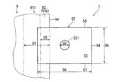
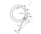
- FIG. 2 is a schematic top view for explaining the configuration of the substrate processing apparatus of FIG. 1. It is a schematic perspective view for demonstrating the structure of the substrate processing apparatus of FIG. 3 is a schematic cross-sectional view of another member and the peripheral edge of the substrate taken along the cutting line A1-A1 of FIG. It is a cross-sectional schematic diagram for demonstrating the other positional relationship of the another member of FIG. 4, and a board
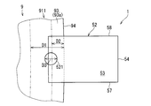
- FIG. 5 is a top schematic view showing a discharge target area in another member of FIG. 4. It is an upper surface schematic diagram which shows the other example of arrangement
- FIG. 7 is a schematic top view for explaining another configuration example of another member of FIG. 1. It is a cross-sectional schematic diagram which shows the peripheral part vicinity of the board
- FIG. 17 is a schematic top view for explaining the configuration of the substrate processing apparatus of FIG. 16.
- FIG. 18 is a schematic top view for explaining an operation at the time of loading / unloading a substrate of another member of FIG. 17.
- the vertical direction is the vertical direction, and the substrate side is above the spin chuck.
- FIGS. 1 to 3 are diagrams for explaining the configuration of the substrate processing apparatus 1 according to the embodiment.
- 1 and 2 are a schematic side view and a schematic top view of the substrate processing apparatus 1.
- FIG. 3 is a schematic perspective view of the substrate processing apparatus 1 as viewed obliquely from above.
- the substrate 9 is rotated around the rotation axis a1 by the spin chuck 21 in a predetermined rotation direction (the direction of the arrow AR1) with the nozzle 51 and the separate member 52 disposed at the respective processing positions.
- the state is shown.
- the nozzle 51, the separate member 52, and the like arranged at the retreat position are indicated by virtual lines.
- descriptions of some components such as the scattering prevention unit 3 among the components of the substrate processing apparatus 1 are omitted.
- the surface shape of the substrate 9 is substantially circular. Loading and unloading of the substrate 9 to and from the substrate processing apparatus 1 is performed by a robot or the like in a state where the nozzle 51 and the like are arranged at the retracted position. The substrate 9 carried into the substrate processing apparatus 1 is detachably held by the spin chuck 21.
- processing liquid includes “chemical liquid” used for chemical liquid processing and “rinsing liquid (also referred to as“ cleaning liquid ”)” used for rinsing for rinsing the chemical liquid. It is.
- the substrate processing apparatus 1 includes a rotation holding mechanism 2, a scattering prevention unit 3, a processing unit 5, a nozzle moving mechanism 6, and a control unit 130. These units 2 to 3 and 5 to 6 are electrically connected to the control unit 130 and operate in accordance with instructions from the control unit 130.
- the control unit 130 for example, the same one as a general computer can be adopted. That is, the control unit 130 stores, for example, a CPU that performs various arithmetic processes, a ROM that is a read-only memory that stores basic programs, a RAM that is a readable and writable memory that stores various information, control software, data, and the like. It has a magnetic disk to keep.
- the CPU as the main control unit performs arithmetic processing according to the procedure described in the program, thereby controlling each unit of the substrate processing apparatus 1.
- FIG. 13 is a cross-sectional view showing the vicinity of the peripheral portion of the substrate 9 in a plane including the central axis.
- the cross-sectional view of FIG. 13 is a cross-sectional view (also referred to as a “longitudinal cross-sectional view”) in a plane including the rotation axis a1 of the substrate 9 (spin chuck 21) passing through the center c1 of the main surface of the substrate 9.
- a substrate 9 to be processed by the substrate processing apparatus 1 includes, for example, a central layer 901 made of silicon (Si), a lower layer film 902 formed outside the central layer 901, and an outer side of the lower layer film 902.
- the surface shape of the substrate 9 is substantially circular.
- the radius of the substrate 9 is, for example, 150 mm.
- Lower layer 902 for example, thermal oxide film (Th-SiO 2), or an insulating film (e.g., Hf (Hafunyumu) film, or oxide Hf film, etc.).
- the upper layer film 903 is, for example, a barrier metal film (for example, a TiN film, a TaN film, etc.) or a metal film (for example, an Al film, a W film, a NiSi film, a Cu film, etc.).
- a barrier metal film for example, a TiN film, a TaN film, etc.
- a metal film for example, an Al film, a W film, a NiSi film, a Cu film, etc.
- the substrate 9 to be processed in the substrate processing apparatus 1 may have, for example, a two-layer structure of the central layer 901 and the lower layer film 902 or a structure of four or more layers. May be.
- the surface on which the device pattern is formed is referred to as an “upper surface 91”.
- a surface opposite to the upper surface 91 is referred to as a “lower surface 92”.
- a region where the device pattern is formed on the upper surface 91 is referred to as a “device region 90”.
- the peripheral region outside the device region 90 on the upper surface 91 is referred to as “upper surface peripheral portion 911”.
- the end 94 of the substrate 9 is the outermost portion of the surface of the substrate 9 along the radial direction of the substrate 9.
- the shape of the end 94 in the top view of the substrate 9 is circular.
- an annular region having a minute width D1 from the end 94 on the lower surface 92 is referred to as a “lower surface peripheral portion 921”.
- a region obtained by combining the upper surface peripheral portion 911 and the lower surface peripheral portion 921 is also simply referred to as “peripheral portion”.
- the end surface 93 of the substrate 9 is an annular portion excluding the flat portions of the upper surface 91 and the lower surface 92 of the surface of the substrate 9.
- D2 minute width
- the end surface 93 projects outwardly from the substrate 9 along the radial direction of the substrate 9 and is curved.
- the annular portion above the end 94 is an upper end surface 93 a
- the annular portion below the end 94 is a lower end surface 93 b.
- the upper end surface 93 a is included in the upper surface peripheral portion 911
- the lower end surface 93 b is included in the lower surface peripheral portion 921.
- the substrate processing apparatus 1 treats the substrate 9 as a processing target and performs processing on the upper surface peripheral edge portion 911 and the lower end surface 93b (for example, processing for removing a thin film formed on the upper surface peripheral edge portion 911 and the lower end surface 93b). be able to.
- the rotation holding mechanism 2 is a mechanism that can rotate while holding the substrate 9 in a substantially horizontal posture with one main surface thereof facing upward.
- the rotation holding mechanism 2 rotates the substrate 9 about a vertical rotation axis a1 passing through the center c1 of the main surface.
- the rotation holding mechanism 2 includes a spin chuck (“holding member”, “substrate holding part”) 21 that is a disk-like member smaller than the substrate 9.
- the spin chuck 21 is provided such that the upper surface thereof is substantially horizontal and the center axis thereof coincides with the rotation axis a1.
- a cylindrical rotary shaft 22 is connected to the lower surface of the spin chuck 21.
- the rotating shaft portion 22 is arranged in such a posture that its axis is along the vertical direction.
- the axis of the rotary shaft portion 22 coincides with the rotary shaft a1.
- a rotation drive unit (for example, a servo motor) 23 is connected to the rotation shaft unit 22.
- the rotation drive unit 23 drives the rotation shaft unit 22 to rotate about its axis.
- the spin chuck 21 can rotate around the rotation axis a ⁇ b> 1 together with the rotation shaft portion 22.
- the rotation drive unit 23 and the rotation shaft unit 22 are a rotation mechanism 231 that rotates the spin chuck 21 about the rotation axis a1.
- the rotating shaft portion 22 and the rotation driving portion 23 are accommodated in a cylindrical casing 24.
- a through hole (not shown) is provided at the center of the spin chuck 21 and communicates with the internal space of the rotary shaft 22.
- a pump (not shown) is connected to the internal space via a pipe (not shown) and an on-off valve.
- the pump and the on-off valve are electrically connected to the control unit 130.
- the control unit 130 controls operations of the pump and the on-off valve.
- the pump can selectively supply a negative pressure and a positive pressure under the control of the control unit 130.
- the pump supplies a negative pressure with the substrate 9 placed on the upper surface of the spin chuck 21 in a substantially horizontal posture, the spin chuck 21 holds the substrate 9 by suction from below.
- the pump supplies positive pressure, the substrate 9 can be removed from the upper surface of the spin chuck 21.
- the scattering prevention unit 3 receives a processing liquid or the like scattered from the substrate 9 rotated together with the spin chuck 21.
- the scattering prevention unit 3 includes a splash guard 31.
- the splash guard 31 is a cylindrical member having an open upper end and is provided so as to surround the rotation holding mechanism 2.
- a guard may be further provided outside the splash guard 31 so as to surround the rotation holding mechanism 2.
- the splash guard 31 includes an annular bottom, a cylindrical inner wall extending upward from the inner edge of the bottom, and a cylindrical outer wall extending upward from the outer edge of the bottom. At least the vicinity of the tip of the inner wall portion is accommodated in the inner space of the flange-shaped member 241 provided in the casing 24 of the rotation holding mechanism 2.
- the upper part (“upper end portion”, “upper end portion”) of the outer wall portion extends inward and upward. That is, the upper part extends obliquely upward toward the rotation axis a1.
- a drainage groove (not shown) communicating with the space between the inner wall portion and the outer wall portion is formed at the bottom of the splash guard 31.
- the drainage groove is connected to a factory drainage line.
- the drainage groove is connected to an exhaust fluid mechanism that forcibly exhausts the groove and places the space between the inner wall portion and the outer wall portion in a negative pressure state.
- the space between the inner wall portion and the outer wall portion is a space for collecting and draining the processing liquid used for processing the substrate 9, and the processing liquid collected in this space is discharged from the drain groove. Drained.
- the splash guard 31 is provided with a guard driving mechanism 32 that moves the splash guard 31 up and down.
- the guard drive mechanism 32 is configured by, for example, a stepping motor.
- the splash guard 31 is driven between the upper position and the lower position under the driving of the guard drive mechanism 32.
- the upper position of the splash guard 31 is a position where the upper end edge of the splash guard 31 is disposed on the side of the substrate 9 held on the spin chuck 21 and above.
- the lower position of the splash guard 31 is a position where the upper edge of the splash guard 31 is disposed below the upper surface of the spin chuck 21.
- the guard drive mechanism 32 is electrically connected to the control unit 130 and operates under the control of the control unit 130. That is, the position of the splash guard 31 is controlled by the control unit 130.
- the substrate processing apparatus 1 does not include the scattering prevention unit 3, the usefulness of the present invention is not impaired.
- the processing unit 5 performs processing on the upper surface peripheral edge portion 911 and the lower end surface 93 b of the substrate 9 held on the spin chuck 21. Specifically, the processing unit 5 supplies the processing liquid to the upper surface peripheral edge portion 911 of the substrate 9 held on the spin chuck 21.
- the processing unit 5 includes a nozzle holding member 50, a nozzle 51, another member 52, and a processing liquid supply unit 83.
- the nozzle holding member 50 is a member that integrally holds the nozzle 51 and the separate member 52.
- the nozzle holding member 50 is attached to the tip of a long arm 63 provided in the nozzle moving mechanism 6 described later.
- the arm 63 extends along a horizontal plane.
- the nozzle holding member 50 is formed, for example, by joining a plate-like member extending along a vertical plane and a protruding member protruding from the upper end of the plate-like member.
- the upper end of the plate-like member is attached to the tip of the arm 63.
- the protruding member protrudes along the extending direction of the arm 63 on the side opposite to the arm 63 with respect to the plate-like member.
- the nozzle 51 is attached to the tip of the protruding member.
- Another member 52 is attached to the lower end of the plate-like member of the nozzle holding member 50.
- the nozzle 51 discharges the liquid flow L1 of the processing liquid so as to hit a part of the upper surface peripheral edge portion 911 of the substrate 9 held and rotated on the spin chuck 21.
- the liquid flow L1 is discharged from the discharge port of the nozzle 51 in a liquid column shape.
- the tip part (lower end part) of the nozzle 51 protrudes downward and has a discharge port at the tip.
- the discharge port faces the upper surface of the separate member 52.
- the nozzle 51 is connected to a processing liquid supply unit 83 which is a piping system for supplying a processing liquid thereto. Specifically, one end of a pipe 832 of the processing liquid supply unit 83 is connected to the upper end of the nozzle 51.
- the nozzle 51 is supplied with the processing liquid from the processing liquid supply unit 83, and discharges the liquid flow L1 of the supplied processing liquid in a liquid columnar shape from the discharge port at the tip.
- the nozzle 51 discharges the processing liquid from above the discharge target area 521 so that at least a part of the nozzle 51 hits the discharge target area 521 included in the upper surface of the separate member 52.
- the processing liquid supply unit 83 supplies the processing liquid to the nozzle 51.
- the processing liquid supply unit 83 is configured by combining a processing liquid supply source 831, a pipe 832, and an on-off valve 833.
- the treatment liquid includes a chemical liquid and a rinse liquid.
- SC-1, DHF, SC-2 or the like is used as the chemical solution.
- the rinsing liquid for example, pure water, warm water, ozone water, magnetic water, reducing water (hydrogen water), various organic solvents (ionic water, IPA (isopropyl alcohol), functional water (CO 2 water, etc.), etc. are used. It is done.
- the nozzle 51 When the processing liquid is supplied from the processing liquid supply unit 83 to the nozzle 51, the nozzle 51 discharges the liquid flow L1 of the processing liquid.
- the on-off valve 833 provided in the processing liquid supply unit 83 is opened / closed under the control of the control unit 130 by a valve opening / closing mechanism (not shown) that is electrically connected to the control unit 130. That is, the control unit 130 controls the discharge mode of the processing liquid from the nozzle 51 (specifically, the discharge start timing, discharge end timing, discharge flow rate, etc.). That is, the nozzle 51 of the processing unit 5 discharges the liquid flow L1 of the processing liquid so as to hit the upper surface peripheral portion 911 of the substrate 9 rotating around the rotation axis a1 under the control of the control unit 130.
- the separate member 52 is a member disposed outside the substrate 9 along the radial direction of the substrate 9 with a gap from the end surface 93 of the substrate 9 held by the spin chuck 21. More specifically, the center of gravity of the separate member 52 is disposed outside the substrate 9 along the radial direction of the substrate 9.
- the upper surface of the separate member 52 includes at least a part of the ejection target area 521. The configuration of the separate member 52 and other configuration examples will be described later.
- the nozzle moving mechanism 6 is a mechanism that moves the nozzle 51 and the separate member 52 between the processing position and the retracted position.
- the nozzle moving mechanism 6 includes an arm 63 that extends horizontally, a nozzle base 66, a lift drive unit 68, and a rotation drive unit 69.
- the nozzle holding member 50 is attached to the tip portion of the arm 63.
- the base end portion of the arm 63 is connected to the upper end portion of the nozzle base 66.
- the nozzle base 66 is disposed outside the casing 24 in such a posture that its axis is along the vertical direction.
- the nozzle base 66 includes a rotating shaft that extends in the vertical direction along the axis and is rotatable around the axis.
- the axis of the nozzle base 66 coincides with the axis of the rotation axis.
- the upper end portion of the nozzle base 66 is attached to the upper end of the rotation shaft.
- the nozzle base 66 is provided with a rotation drive unit 69 that rotates the rotation axis about the axis.
- the rotation drive unit 69 includes, for example, a servo motor.
- the nozzle base 66 is provided with a lift drive unit 68.
- the elevating drive unit 68 includes, for example, a servo motor.
- the elevating drive unit 68 elevates and lowers the rotation axis of the nozzle base 66 along the axis through a ball screw mechanism having a ball screw connected to the output shaft.
- the rotation drive unit 69 rotates the upper end portion of the nozzle base 66 via the rotation shaft of the nozzle base 66. As the upper end portion rotates, the nozzle holding member 50 also rotates around the axis of the nozzle base 66. Thereby, the rotation drive part 69 moves the nozzle 51 and the separate member 52 horizontally. That is, the rotation drive unit 69 is a “radial direction drive unit” that can move the separate member 52 in the radial direction of the substrate 9.
- the elevating drive unit 68 elevates and lowers the nozzle holding member 50, that is, the nozzle 51 and the separate member 52, by elevating and lowering the rotation axis of the nozzle base 66 along the axis.
- the raising / lowering driving unit 68 and the rotation driving unit 69 cooperate with each other at the processing position in the vicinity of the substrate 9 held by the spin chuck 21 and on the outer side and the upper side along the radial direction of the substrate 9 from the processing position.
- the nozzle holding member 50 is moved between the retracted positions. When the nozzle holding member 50 is disposed at the processing position, the nozzle 51 and the separate member 52 are disposed at the respective processing positions.
- Treatment positions of the nozzle holding member 50, the nozzle 51, and the separate member 52 are positions where they do not interfere with the transport path of the substrate 9 and do not interfere with each other.
- Each retreat position is, for example, a position outside and above the splash guard 31.
- the driving units 68 and 69 are electrically connected to the control unit 130 and operate under the control of the control unit 130. That is, the position of the nozzle holding member 50 is controlled by the control unit 130. That is, the positions of the nozzle 51 and the separate member 52 are controlled by the control unit 130.
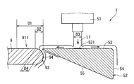
- FIG. 4 is a schematic cross-sectional view of the peripheral portion of the separate member 52 and the substrate 9 along the cutting line A1-A1 (FIG. 2).
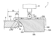
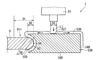
- FIG. 5 is a schematic cross-sectional view for explaining the separate member 52 and the substrate 9 arranged in a positional relationship different from the positional relationship in FIG. 6 to 9 are schematic cross-sectional views for explaining separate members 52A to 52D according to other embodiments. 4 to 9 are shown by longitudinal sectional views.
- FIG. 10 is a schematic top view illustrating an example of the ejection target area 521 in the separate member 52.
- 12 is a schematic top view illustrating another example of the arrangement of the ejection target area 521 in another member 52.
- FIG. FIG. 12 is a schematic top view for explaining another member 52E as another configuration example of the different member 52.
- the separate member 52 is a triangular prism-shaped member whose axis extends substantially along the circumferential direction of the substrate 9.
- the vertical cross section of the separate member 52 is substantially triangular.
- the separate member 52 includes an upper surface 53, an outer surface 54, an inner surface (“opposing surface”) 55, a side surface 57, and a side surface 58.
- the upper surface 53 is a substantially horizontal rectangular surface.
- the outer side surface 54 is the outermost surface of the separate member 52 along the radial direction of the substrate 9, and is provided substantially perpendicular to the radial direction of the substrate 9.
- the inner surface 55 faces the end surface 93 of the substrate 9 and is inclined with respect to the rotation axis a1 so as to approach the rotation axis a1 from the lower end toward the upper end.
- the side surfaces 57 and 58 are substantially triangular surfaces perpendicular to the upper surface 53 and the outer surface 54, respectively.
- the side surfaces 57 and 58 may be parallel to each other or may extend along the radial direction of the substrate 9.
- the inner end of the upper surface 53 on the rotation axis a1 side is located closer to the rotation axis a1 side along the radial direction of the substrate 9 than the end 94 of the substrate 9, that is, the periphery.
- the inner end is located above the upper peripheral edge 911 of the substrate 9.
- the length D5 (FIG. 10) of the separate member 52 in the radial direction of the substrate 9 is, for example, about 10 mm.
- the length D6 (FIG. 10) of the separate member 52 in the tangential direction of the end 94 of the substrate 9 is, for example, about 20 mm.
- the height D7 (FIG. 4) of the separate member 52 along the rotation axis a1 is, for example, about 5 mm.
- the separate member 52E includes an inner surface that faces the end surface 93 of the substrate 9 with a gap therebetween, and the inner surface extends in an arc shape in the circumferential direction of the substrate 9 along the peripheral edge (end 94) of the substrate 9. . Thereby, the uniformity of the process width in the upper surface peripheral part 911 can be improved.
- the separate member 52 includes a substantially circular discharge target area 521.
- the ejection target area 521 is a virtual area.
- the diameter of the liquid L1 of the processing liquid discharged from the nozzle 51 is substantially the same as the diameter D3 of the discharge target area 521.
- the diameter D3 is substantially the same length as the width D2 of the end surface 93 of the substrate 9.
- the entire ejection target area 521 is included in the upper surface 53 of the separate member 52.
- a part of the ejection target region 521 may protrude from the inner end of the upper surface 53 of the separate member 52 to the rotation axis a ⁇ b> 1 side.
- the processing liquid discharged from the nozzle 51 as the liquid flow L1 so as to hit the discharge target area 521 spreads from the discharge target area 521 to the periphery on the upper surface 53.
- a part of the processing liquid flows through the upper surface 53 and is discharged to the outside of the separate member 52 from the inner end of the upper surface 53 on the rotation axis a1 side.
- a gap 97 (FIG. 4) between the separate member 52 and the end surface 93 of the substrate 9 is set so that the discharged processing liquid strikes the upper peripheral edge 911 of the substrate 9 from above. Therefore, the processing liquid hits the upper surface peripheral edge portion 911 from above from the upper surface peripheral edge portion 911.
- a distance D4 along the radial direction of the substrate 9 with the boundary between the flat portion of the upper surface peripheral edge portion 911 and the upper end surface 93a and the inner side surface 55 is substantially the same as the width D2 of the end surface 93.
- the processing liquid that hits the upper surface peripheral edge portion 911 flows downward along the end surface 93 of the substrate 9 through the gap 97.
- the portion on the end 94 side and the lower end surface 93b of the upper peripheral edge portion 911 of the substrate 9 with respect to the portion that has been exposed to the processing liquid are processed with the processing liquid.
- the separate member 52 may be arranged so that the upper surface 53 of the separate member 52 is a horizontal plane having substantially the same height as the flat portion of the upper surface 91 of the substrate 9.
- the distance D4 along the radial direction of the substrate 9 with the boundary between the flat portion of the upper surface peripheral edge portion 911 and the upper end surface 93a and the inner side surface 55 is substantially the same as the width D2 of the end surface 93 as in FIG.
- the distance D4 is a distance from the boundary to the inner end of the upper surface 53 of the separate member 52.
- the separate member 52A includes a horizontal upper surface 53A and an outer surface 54A that is a vertical surface.
- the upper surface 53A and the outer surface 54A are configured similarly to the upper surface 53 and the outer surface 54 of the separate member 52 (FIG. 4).
- the separate member 52 ⁇ / b> A includes an internal surface 55 ⁇ / b> A that faces the end surface 93 of the substrate 9 instead of the internal surface 55 of the separate member 52.
- the inner side surface 55A approaches the rotation axis a1 from the lower end toward the upper end, and protrudes obliquely upward with respect to the rotation axis a1 and is curved.
- the separate member 52A includes a lower surface 56A that connects the lower ends of the inner surface 55A and the outer surface 54A and is parallel to the upper surface 53A.
- the separate member 52B shown in FIG. 7 may be employed instead of the separate member 52.
- the separate member 52B includes an upper surface 53B and an outer surface 54B configured in substantially the same manner as the upper surface 53 and the outer surface 54 of the separate member 52, and includes a lower surface 56B parallel to the upper surface 53B.
- the lower surface 56B is formed in the same shape and size as the upper surface 53B.
- the separate member 52 ⁇ / b> B further includes an internal surface 55 ⁇ / b> B that faces the end surface 93 of the substrate 9 instead of the internal surface 55 of the separate member 52.
- the cross-sectional shape of the inner side surface 55 ⁇ / b> B in the plane including the rotation axis a ⁇ b> 1 is curved along the end surface 93 of the substrate 9.
- the upper surface 53B is located above the upper surface 91 of the substrate 9, and the lower surface 56B is located below the lower surface 92 of the substrate 9.
- FIG. 8 another member 52C shown in FIG. 8 may be employed instead of the separate member 52.
- the separate member 52C has a shape in which the separate member 52B is contracted along the direction of the rotation axis a1.
- the separate member 52C includes an upper surface 53C, a lower surface 56C, an outer surface 54C, and an inner surface 55C.
- the upper surface 53C is a horizontal surface having the same shape as the upper surface 53B of the separate member 52B.
- the lower surface 56C is a horizontal surface having the same shape as the lower surface 56B of the separate member 52B.
- the upper surface 53C is included in the same horizontal plane as the flat portion of the upper surface 91 of the substrate 9.
- the lower surface 56 ⁇ / b> C is included in the same horizontal plane as the flat portion of the lower surface 92 of the substrate 9.
- the outer side surface 54C is a vertical surface.
- the inner side surface 55C is formed by connecting the inner ends of the upper surface 53C and the lower surface 56C.
- the cross-sectional shape of the inner side surface 55 ⁇ / b> C in the plane including the rotation axis a ⁇ b> 1 is curved along the end surface 93 of the substrate 9.
- the separate member 52D includes an upper surface 53D, a lower surface 56D, an outer surface 54D, and an inner surface 55D.
- the different member 52D includes an inner side surface 55D that is a vertical surface instead of the curved inner side surface 55C of the different member 52C.
- the inner side surface 55D is perpendicular to the radial direction of the substrate 9.
- the separate member 52D has a rectangular parallelepiped shape.
- the upper surface 53D and the lower surface 56D have the same shape as the upper surface 53C and the lower surface 56C of the separate member 52C.
- the upper surface 53D is included in the same horizontal plane as the flat portion of the upper surface 91 of the substrate 9, and the lower surface 56D is included in the same horizontal plane as the flat portion of the lower surface 92. Since the inner side surface 55D is a flat surface, a gap is provided between the end 94 of the end surface 93 of the substrate 9 and the inner side surface 55D. For this reason, the distance (distance in the radial direction of the substrate 9) D4 between the boundary between the flat portion of the upper surface peripheral edge portion 911 and the upper end surface 93a and the inner surface 55D is longer than the width D2 of the end surface 93.
- the nozzle 51 and the separate member 52 are integrally held and moved by the nozzle holding member 50, but the substrate processing apparatus 1 does not include the nozzle holding member 50, and the nozzle 51 and the separate member 52 are moved.
- a lifting mechanism and a moving mechanism in the radial direction of the substrate 9 may be separately provided for each of the above.
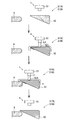
- FIG. 14 is a flowchart showing an example of the operation of the substrate processing apparatus 1.
- FIG. 15 is a diagram for explaining the operation shown in the flowchart of FIG.
- the nozzle 51 and the separate member 52 are arranged at respective processing positions, and the processing liquid is discharged from the nozzle 51 to the upper peripheral edge 911 of the substrate 9.
- the nozzle 51 and the separate member 52 are disposed, for example, in the retracted position, and the spin chuck 21 holds the substrate 9 but does not rotate. To do.
- the control unit 130 of the substrate processing apparatus 1 controls the rotation mechanism 231 to start the rotation of the spin chuck 21 around the rotation axis a1 (Step S110 in FIGS. 14 and 15).
- the rotation is performed at a rotation speed of 2000 rpm, for example.
- the control unit 130 controls the elevating drive unit 68 and the rotation drive unit 69 to move the nozzle holding member 50 from the retracted position to an outer position on the side of the substrate 9 (in the radial direction of the substrate 9) with respect to the processing position.
- the raising / lowering drive part 68 and the rotation drive part 69 arrange
- the respective outer positions of the nozzle 51 and the separate member 52 are positioned on the outer side of the substrate 9 (in the radial direction) with respect to the respective processing positions.
- the control unit 130 controls the processing unit 5 to cause the nozzle 51 to start discharging the processing liquid to the discharge target region 521 on the separate member 52 (step S130 in FIGS. 14 and 15).
- the processing liquid discharged from the nozzle 51 to the discharge target area 521 of the separate member 52 spreads along the upper surface 53 of the separate member 52 and is discharged from the inner end of the separate member 52 to the outside of the separate member 52.
- the processing liquid discharged to the outside of the separate member 52 does not hit the peripheral edge portion 911 of the substrate 9.
- the control unit 130 waits until the discharge state of the processing liquid flow L1 by the nozzle 51 is stabilized (step S140 in FIGS. 14 and 15).
- the waiting time is acquired in advance by an experiment or the like and stored in the ROM or the like of the control unit 130, for example.
- the control unit 130 controls the rotation driving unit 69 to arrange the nozzle holding member 50 at the processing position on the end surface 93 side of the substrate 9 along the radial direction of the substrate 9.
- the rotation drive unit 69 arranges the nozzle 51 and the separate member 52 at the respective processing positions (also referred to as “inner positions”) on the side of the substrate 9, more specifically on the side of the end face 93. (Step S150 in FIGS. 14 and 15).
- the nozzle 51 continues to discharge the processing liquid.
- the discharge state of the liquid flow L1 of the processing liquid discharged to the discharge target region 521 is stable. That is, the state of the liquid film of the processing liquid flowing from the discharge target area 521 toward the inner end of the upper surface 53 of the separate member 52 is also stable.
- the controller 130 processes the upper surface peripheral edge 911 of the substrate 9 by causing the nozzle 51 arranged at the processing position to continue discharging the processing liquid as it is (step S160 in FIGS. 14 and 15).
- the control unit 130 controls the processing unit 5 to stop the discharge of the processing liquid from the nozzle 51 (FIG. 14). , Step S170 in FIG. 15).
- the control unit 130 causes the rotation driving unit 69 to move the nozzle 51 and the separate member 52 to the outer positions while discharging the processing liquid from the nozzle 51 before stopping the processing unit 5 from discharging the processing liquid from the nozzle 51. After the arrangement, the discharge of the processing liquid from the nozzle 51 may be stopped.
- the control unit 130 controls the rotation mechanism 231 to stop the rotation of the spin chuck 21 (Step S180 in FIGS. 14 and 15), and ends the operation of the flowchart in FIG.
- FIG. 16 is a schematic side view for explaining the configuration of the substrate processing apparatus 1A according to another embodiment.
- FIG. 17 is a schematic top view for explaining the configuration of the substrate processing apparatus 1A.
- FIG. 18 is a schematic top view for explaining the operation of the separate member 73 of the substrate processing apparatus 1A when the substrate 9 is carried in and out of the substrate processing apparatus 1A.
- the substrate processing apparatus 1 ⁇ / b> A is an apparatus that discharges the processing liquid to the upper surface peripheral portion 911 and the like of the substrate 9 that is rotated about the rotation axis a ⁇ b> 1 and performs processing on the upper peripheral portion 911 and the like. is there.
- the substrate processing apparatus 1 ⁇ / b> A includes a pedestal 25 instead of the nozzle holding member 50 of the substrate processing apparatus 1 and a separate member 73 instead of the separate member 52 as a configuration different from the substrate processing apparatus 1.
- the nozzle 51 is fixed below the tip of the arm 63.
- the pedestal 25 is an annular member, and is fixed to the rotary shaft portion 22 by inserting the rotary shaft portion 22 through the central hole.
- the axis of the pedestal 25 is provided so as to coincide with the rotation axis a ⁇ b> 1 like the axis of the rotation shaft portion 22. Thereby, the rotating shaft portion 22 is rotated at the same speed in the same direction as the substrate 9 around the rotating shaft a1.
- the separate member 73 is a plate-like annular member that surrounds the peripheral edge (end 94, end face 93) of the substrate 9 along the circumferential direction of the substrate 9 with the rotation axis a1 as the center.
- the separate member 73 includes a plurality of (three in the illustrated example) arc-shaped members 73a to 73c. One ends of the two arcuate members 73a and 73b in the circumferential direction of the substrate 9 are opposed to each other.
- the arc-shaped members 73a and 73b are provided so as to be rotatable in a horizontal plane around the other end.
- the arc-shaped members 73a and 73b extend along the length of about a quarter of the peripheral edge of the substrate 9, and the arc-shaped member 73c extends along the length of about half the peripheral edge of the substrate 9. It is installed.
- the upper surface of the separate member 73 is a substantially horizontal plane.
- the shape of the longitudinal section of the separate member 73 (arc-shaped members 73a to 73c) for example, the cross-sectional shapes of the separate members 52 and 52A to 52D are employed.
- the arcuate member 73c is fixed to the pedestal 25 with a gap from the upper surface of the pedestal 25 by two projecting pieces 75 projecting upward from the upper surface of the pedestal 25.
- the arc-shaped members 73a and 73b are fixed to the pedestal 25 via projecting pieces 74 attached to the other ends. More specifically, the projecting piece 74 is configured to be rotatable about its axis by a rotation drive unit (“rotation mechanism”) 79 configured by a stepping motor or the like.
- the axis is the vertical axis.
- the substrate processing apparatus 1 ⁇ / b> A causes the rotation mechanism 231 to rotate the pedestal 25 to rotate the separate member 73 at the same rotational speed as the substrate 9 through the pedestal 25 and the like.
- the rotation drive unit 23, the rotation shaft unit 22, the pedestal 25, the rotation drive unit 79, the projecting piece 74, and the projecting piece 75 are rotation mechanisms 251 that rotate the separate member 73 around the rotation axis a1.
- the arc-shaped members 73 a and 73 b are arranged so that each projecting piece 74, that is, each other end has a rotation center at the other end, and the one end is larger than the diameter of the substrate 9. It is rotated via the projecting piece 74 by the rotation drive unit 79 so as to leave.
- the substrate is carried in and out of the substrate processing apparatus 1 with one end of each of the arc-shaped members 73a and 73b separated from each other.
- the substrate processing apparatus 1 ⁇ / b> A has the same configuration as the substrate processing apparatus 1 except for the above differences, and performs processing on the upper peripheral edge portion 911 of the substrate 9.
- the separate member 73 is disposed outside the substrate 9 along the radial direction of the substrate 9 with a gap from the end surface 93 of the substrate 9 held by the spin chuck 21.
- the nozzle 51 discharges the processing liquid from above the discharge target area 731 so that at least a part of the nozzle 51 hits the discharge target area 731 included on the upper surface of the separate member 73.
- the processing liquid that has hit the ejection target region 731 flows through the upper surface of the separate member 73 and is discharged from the inner end of the upper surface on the rotation axis a ⁇ b> 1 side. It is set to hit the upper surface peripheral edge portion 911 from above.
- the substrate processing apparatus 1A moves the nozzle 51 and the separate member 73 separately.
- the nozzle 51 is moved in the radial direction and the vertical direction of the substrate 9 by the elevation drive unit 68 and the rotation drive unit 69, but the separate member 73 is the base 25 except for a part thereof (arc-shaped members 73 a and 73 b). And rotates together with the base 25, that is, together with the substrate 9.
- the entire discharge target area 731 may be included on the upper surface of the separate member 73, or a part of the discharge target area 731 may protrude from the inner end of the upper surface of the separate member 73 toward the rotation axis a1.
- a drive mechanism for driving the arc-shaped members 73a to 73c between each processing position and an outer position on the outer side in the radial direction of the substrate 9 with respect to the processing position is a rotation driving unit 79 and each projecting piece 75.
- the separate member 73 (arc-shaped members 73a to 73c) is arranged at the outer position, the processing liquid is discharged from the nozzle 51 to the separate member 73, and the stable discharge state is waited.
- Another member 73 (arc-shaped members 73a to 73c) can be arranged at the processing position.
- the upper surface of the separate member 52 (73) hits the discharge target region 521 (731).
- a processing liquid is discharged from the nozzle 51.
- the separate member 52 (73) is disposed outside the substrate 9 along the radial direction of the substrate 9 with a gap from the end surface 93 of the substrate 9, and the gap hits the ejection target region 521 (731).
- the processing liquid is set so as to flow on the upper surface of the separate member 52 (73), be discharged from the inner end of the upper surface on the side of the rotation axis a1, and hit the upper peripheral edge 911 of the substrate 9 from above. Therefore, the processing width of the upper surface peripheral portion 911 of the substrate 9 by the processing liquid can be narrowed, and the uniformity of the processing width can be improved.
- the entire ejection target region 521 (731) is included on the upper surface of the separate member 52 (73). Accordingly, all the processing liquid that hits the upper surface peripheral edge portion 911 of the substrate 9 flows from the ejection target region 521 (731) to the upper surface of the separate member 52 (73) and is discharged from the inner end of the upper surface on the rotation axis a1 side. It is a liquid. Therefore, the distance along the radial direction of the substrate 9 between the position where the processing liquid hits the upper peripheral edge 911 of the substrate 9 and the inner end of the separate member 52 (73) can be shortened. Thereby, the processing width of the upper surface peripheral edge portion 911 of the substrate 9 by the processing liquid can be further narrowed.
- the nozzle holding member 50 integrally holds the nozzle 51 and the separate member 52, so that it hits a certain discharge target region 521.
- the processing liquid is discharged.
- the discharge mode of the processing liquid discharged from the inner end can be stabilized. Therefore, the processing width of the upper surface peripheral edge portion 911 of the substrate 9 can be stabilized.
- the separate member 73 is an annular member that surrounds the periphery of the substrate 9 along the circumferential direction of the substrate 9 with the rotation axis a1 as the center. Yes, the separate member 73 is rotated at the same rotational speed as the substrate 9. Therefore, even when the separate member 73 is rotated together with the substrate 9, the uniformity of the processing width of the upper surface peripheral portion 911 of the substrate 9 can be improved.
- the two arc-shaped members 73 a and 73 b are provided adjacent to each other along the circumferential direction of the substrate 9 with one end facing each other. Each of the other ends can be rotated so that each end is separated from the diameter of the substrate 9 with the other ends as the rotation centers. Accordingly, the substrate 9 can be carried in and out of the substrate processing apparatus by the rotation of the two arcuate members 73a and 73b.
- the inner end of the upper surface of the separate member 52 (73) on the rotation axis a 1 side is the radial direction of the substrate 9 rather than the peripheral edge of the substrate 9. Along the axis of rotation a1. Therefore, the processing width of the upper surface peripheral portion 911 of the substrate 9 can be increased.
- the inner surface 55 of the separate member 52 is relative to the rotation axis a1 so as to approach the rotation axis a1 from the lower end toward the upper end. Inclined. Therefore, when the separate member 52 can be moved up and down, the separate member 52 can be disposed at the processing position by the lowering of the separate member 52 from above the processing position.
- the inner surface 55A of the separate member 52A approaches the rotation axis a1 from the lower end toward the upper end, and with respect to the rotation axis a1. It protrudes diagonally upward and is curved. Accordingly, the gap in the radial direction of the substrate 9 between the end surface 93 of the substrate 9 and the separate member 52A can be made more uniform. Thereby, the processing efficiency of the end surface 93 of the substrate 9 can be improved.
- the separate member 52B (52C) includes the inner side surface 55B (55C) facing the end surface 93 of the substrate 9, and the rotation axis a1.
- the cross-sectional shape of the inner side surface 55 ⁇ / b> B (55 ⁇ / b> C) in the plane including it is curved along the end surface 93 of the substrate 9. Accordingly, the gap in the radial direction of the substrate 9 between the end surface 93 of the substrate 9 and the separate member 52B (52C) can be further uniformized. Thereby, the processing efficiency of the end surface 93 of the substrate 9 can be improved.
Landscapes
- Cleaning Or Drying Semiconductors (AREA)
- Engineering & Computer Science (AREA)
- Automation & Control Theory (AREA)
Abstract
本発明は、基板の周縁部の処理幅を細くするとともに、処理幅の均一性を向上させることを目的とする。該目的を達成するために、本発明の基板処理装置は、基板を下方から略水平に保持し、所定の回転軸を中心に回転可能に設けられた保持部材と、保持部材を、回転軸を中心に回転させることができる回転機構と、保持部材に保持されている基板の端面と隙間を隔てて基板の径方向に沿って基板の外側に配置される別部材と、少なくとも一部が別部材の上面に含まれる吐出目標領域に当たるように吐出目標領域の上方から処理液を吐出するノズルと、を備える。別部材と基板の端面との隙間は、吐出目標領域に当たった処理液が、別部材の上面を流れて当該上面の回転軸側の内側端から排出され、基板の上面周縁部に上方から当たるように設定されている。
Description
この発明は、半導体ウエハ、液晶表示装置用ガラス基板、プラズマディスプレイ用ガラス基板、光ディスク用基板、磁気ディスク用基板、光磁気ディスク用基板、フォトマスク用ガラス基板、太陽電池用基板、等(以下、単に「基板」という)に、処理を施す基板処理装置に関する。
このような基板処理装置として、特許文献1には、基板を水平に保持する保持部材と、基板の周縁部に沿って基板の端面と間隔をあけて基板の全周を取り囲むリングとを一緒に回転させつつ、基板の上面中央部に当たるように処理液を吐出する装置が開示されている。当該リング表面は、親水性である。基板表面が疎水性である場合において、当該リングが設けられていない場合には、基板の上面中央部に供給された処理液が遠心力により基板の中央部から周縁部へ拡がる際に放射状に不均一に拡がる。このため、基板の上面全体に均一に処理液を供給することができない。
そこで、特許文献1の装置は、親水性のリングを利用して、基板の中央部から周縁部に達した処理液を、基板の周縁部近傍において膜状に拡げることにより、上面全体に均一に処理液を供給することを図っている。
特許文献2には、下方から基板を水平に保持しつつ回転する保持部材と、基板の周縁部に沿って基板の端面と間隔をあけて基板の全周を取り囲むリングと、回転されている基板の上面中央部に当たるように処理液を吐出するノズルとを備える基板処理装置が開示されている。当該リングは、撥水性が基板よりも高く、回転することなく保持されている。基板の表面が疎水性である場合には、上述のように、上面中央部に供給された処理液は、基板の周縁部近傍において放射状に不均一に拡がる。しかしながら、特許文献2の装置では、処理液が基板の周縁部から外部に排出される際に、基板を取り囲むリングが処理液の流れを妨げることによって処理液の排出を妨げる。これにより、当該装置は、排出される処理液の一部を基板上に溜めて、基板上に処理液の液膜を形成し、基板の上面全域に確実に処理液を供給することを図っている。
基板の中央部にデバイスパターンが形成されるデバイス領域が設けられ、デバイス領域以外の周縁部にエッチング等の処理が行われることがある。特許文献3には、このような基板の周縁部の処理を行う基板処理装置が開示されている。当該装置は、基板の上方に基板表面と対向する遮断部材を有し、基板を略水平面内にて回転させながら遮断部材の周縁部に配置されたノズルから、基板上面の周縁部に向けて処理液を供給して基板上面のうち周縁部のエッチング処理を行う。
基板の処理面のうち周縁部における周縁側の細幅領域のみを処理するためには、基板の処理面のうち当該周縁側の細幅領域のみに処理液を供給する必要が有る。しかしながら、特許文献1、2の基板処理装置は、基板の上面全体に処理液を供給するため、基板の処理面のうち当該細幅領域のみに処理液を供給することができないといった問題がある。
また、特許文献3の装置では、処理液が基板の周縁部のうち平坦部分に向けて吐出されるため、処理液が基板の周縁部において拡がってしまい、基板の処理面のうち周縁部の細幅領域のみを処理することができないといった問題がある。特許文献3の装置によって当該細幅領域を処理するために、処理液の吐出目標領域を、基板の端面ぎりぎりに設定すると、基板の平坦部と端部との境界部分に処理液が当たることによって処理液の流れが乱れる。すなわち、基板に当たった処理液が基板の中心側に拡がったり、端面側に流れたりする。そのため、処理液により処理される処理幅は、基板の周方向に沿って、不均一となり、基板の回転中心側に拡がった処理液の先端を結ぶ線が、基板の周方向に沿って波形となる。このため、基板の周縁部の処理幅が不均一になるといった問題がある。
本発明は、こうした問題を解決するためになされたもので、基板の周縁部を処理する基板処理技術において、基板の周縁部の処理幅を細くできるとともに、処理幅の均一性を向上できる技術を提供することを目的とする。
上記の課題を解決するために、第1の態様に係る基板処理装置は、基板を下方から略水平に保持し、所定の回転軸を中心に回転可能に設けられた保持部材と、前記保持部材を、前記回転軸を中心に回転させることができる回転機構と、前記保持部材に保持されている前記基板の端面と隙間を隔てて前記基板の径方向に沿って前記基板の外側に配置される別部材と、少なくとも一部が前記別部材の上面に含まれる吐出目標領域に当たるように前記吐出目標領域の上方から処理液を吐出するノズルと、を備え、前記別部材と前記基板の端面との前記隙間は、前記吐出目標領域に当たった前記処理液が、前記別部材の上面を流れて当該上面の前記回転軸側の内側端から排出され、前記基板の上面周縁部に上方から当たるように設定されている。
第2の態様に係る基板処理装置は、第1の態様に係る基板処理装置であって、前記吐出目標領域の全てが、前記別部材の上面に含まれている。
第3の態様に係る基板処理装置は、第1または第2の態様に係る基板処理装置であって、前記ノズルと前記別部材とを一体的に保持するノズル保持部材をさらに備える。
第4の態様に係る基板処理装置は、第1または第2の態様に係る基板処理装置であって、前記別部材は、前記回転軸を中心とする前記基板の周方向に沿って前記基板の周縁を取り囲む環状部材であり、前記基板処理装置は、前記別部材を前記基板と同じ回転速度で回転させる前記環状部材用の回転機構をさらに備える。
第5の態様に係る基板処理装置は、第4の態様に係る基板処理装置であって、前記環状部材は、複数の円弧状部材を含んでおり、前記複数の円弧状部材は、前記基板の周方向に沿って隣り合う2つの円弧状部材を含み、前記2つの円弧状部材のそれぞれの前記基板の周方向における一端同士が互いに対向しており、前記2つの円弧状部材は、それぞれの他端を中心に水平面内でそれぞれ回動可能に設けられており、前記基板処理装置は、前記2つの円弧状部材のそれぞれの他端を回転中心としてそれぞれの一端が互いに前記基板の径よりも離れるように前記2つの円弧状部材をそれぞれ回動させることができる回動機構をさらに備える。
第6の態様に係る基板処理装置は、第1から第5の何れか1つの態様に係る基板処理装置であって、前記別部材を前記基板の径方向に移動可能な径方向駆動部と、前記径方向駆動部と、前記ノズルとを制御する制御部と、を備え、前記吐出目標領域に当たった前記処理液が、前記別部材の上面を流れて当該上面の前記回転軸側の内側端から排出され、前記基板の上面周縁部に上方から当たるときの前記別部材の位置によって前記別部材の処理位置を定義したとき、前記制御部は、前記径方向駆動部に前記別部材を前記処理位置よりも前記基板の径方向の外側の外側位置に配置させている間に、前記ノズルに前記吐出目標領域に向けて前記処理液の吐出を開始させるともに、前記ノズルに前記処理液の吐出をさせつつ、前記径方向駆動部に前記別部材を前記外側位置から前記処理位置に移動させる。
第7の態様に係る基板処理装置は、第1から第6の何れか1つの態様に係る基板処理装置であって、前記別部材の上面の前記回転軸側の内側端が、前記基板の周縁よりも前記基板の径方向に沿って前記回転軸側に位置する。
第8の態様に係る基板処理装置は、第1から第7の何れか1つの態様に係る基板処理装置であって、前記別部材は、前記基板の前記端面に対向する内側面を含み、前記内側面がその下端から上端に向かって前記回転軸に近づくように前記回転軸に対して傾斜している。
第9の態様に係る基板処理装置は、第1から第7の何れか1つの態様に係る基板処理装置であって、前記別部材は、前記基板の前記端面に対向する内側面を含み、前記内側面は、その下端から上端に向かって前記回転軸に近づくとともに、前記回転軸に対して斜め上方に張り出して湾曲している。
第10の態様に係る基板処理装置は、第1から第7の何れか1つの態様に係る基板処理装置であって、前記別部材は、前記基板の前記端面に対向する内側面を含み、前記回転軸を含む平面における前記内側面の断面形状は、前記基板の端面に沿って湾曲している。
第11の態様に係る基板処理方法は、基板処理装置における基板処理方法であって、当該基板処理装置は、基板を下方から略水平に保持し、所定の回転軸を中心に回転可能に設けられた保持部材と、前記保持部材を、前記回転軸を中心に回転させる回転機構と、前記基板から離れて配置される別部材と、処理液を吐出可能なノズルと、を備え、前記基板処理方法は、前記別部材を前記基板の端面と隙間を隔てて前記基板の径方向に沿って前記基板の外側に配置するステップと、少なくとも一部が前記別部材の上面に含まれる吐出目標領域に当たるように、前記ノズルに前記吐出目標領域の上方から処理液を吐出させるステップと、を備え、前記別部材と前記基板の端面との前記隙間は、前記吐出目標領域に当たった前記処理液が、前記別部材の上面を流れて当該上面の前記回転軸側の内側端から排出され、前記基板の上面周縁部に上方から当たるように設定されている。
第1および第11の何れの態様に係る発明によっても、別部材の上面に少なくとも一部が含まれる吐出目標領域に当たるようにノズルから処理液が吐出される。別部材は、基板の端面と隙間を隔てて基板の径方向に沿って基板の外側に配置されており、当該隙間は、吐出目標領域に当たった処理液が、別部材の上面を流れて当該上面の回転軸側の内側端から排出され、基板の上面周縁部に上方から当たるように設定されている。従って、処理液による基板の上面周縁部の処理幅を細くできるとともに、処理幅の均一性を向上できる。
第2の態様に係る発明によれば、吐出目標領域の全てが、別部材の上面に含まれている。従って、基板の上面周縁部に当たる処理液は、全て、吐出目標領域から別部材の上面を流れて当該上面の回転軸側の内側端から排出される処理液である。従って、処理液が基板の上面周縁部に当たる位置と、別部材の内側端との基板の径方向に沿った距離を短くできる。これにより、処理液による基板の上面周縁部の処理幅をさらに細くできる。
第3の態様に係る発明によれば、ノズル保持部材がノズルと別部材とを一体的に保持するので、一定の吐出目標領域に当たるように処理液が吐出される。これにより、内側端から排出される処理液の排出態様を安定させることができる。従って、基板の上面周縁部の処理幅を安定させることができる。
第4の態様に係る発明によれば、別部材は、回転軸を中心とする基板の周方向に沿って基板の周縁を取り囲む環状部材であり、別部材は基板と同じ回転速度で回転される。従って、別部材を基板とともに回転させる場合においても、基板の上面周縁部の処理幅の均一性を向上できる。
第5の態様に係る発明によれば、2つの円弧状部材は、一端同士が対向して基板の周方向に沿って隣り合って設けられており、それぞれの他端を回転中心としてそれぞれの一端が互いに基板の径よりも離れるように回動させられ得る。従って、2つの円弧状部材の当該回動によって基板処理装置への基板の搬出入が可能となる。
第6の態様に係る発明によれば、処理位置よりも基板の径方向の外側の外側位置に配置されている別部材の吐出目標領域に向けてノズルが処理液の吐出を開始し、ノズルが処理液を吐出している間に、別部材が外側位置から処理位置に移動される。従って、吐出開始時における処理液の液流の乱れの影響によって、基板の上面周縁部の処理幅が不均一になることを抑制できる。
第7の態様に係る発明によれば、別部材の上面の回転軸側の内側端が、基板の周縁よりも基板の径方向に沿って回転軸側に位置する。従って、基板の上面周縁部の処理幅を広くできる。
第8の態様に係る発明によれば、別部材の内側面は、その下端から上端に向かって回転軸に近づくように回転軸に対して傾斜している。従って、別部材を昇降できる場合、処理位置の上方からの別部材の降下によって別部材を処理位置に配置することができる。
第9の態様に係る発明によれば、別部材の内側面は、その下端から上端に向かって回転軸に近づくとともに、回転軸に対して斜め上方に張り出して湾曲している。従って、基板の端面と別部材との基板の径方向の隙間を、さらに均一化できる。これにより、基板の端面の処理効率を向上できる。
第10の態様に係る発明によれば、別部材は、基板の端面に対向する内側面を含み、回転軸を含む平面における内側面の断面形状は、基板の端面に沿って湾曲している。従って、基板の端面と別部材との基板の径方向の隙間を、さらに均一化できる。これにより、基板の端面の処理効率を向上できる。
以下、図面を参照しながら、実施の形態について説明する。以下の実施の形態は、本発明を具体化した一例であり、本発明の技術的範囲を限定する事例ではない。また、以下に参照する各図では、理解容易のため、各部の寸法や数が誇張または簡略化して図示されている場合がある。上下方向は鉛直方向であり、スピンチャックに対して基板側が上である。
<実施形態について>
<1.基板処理装置1の全体構成>
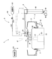
基板処理装置1の構成について、図1~図3を参照しながら説明する。図1~図3は、実施形態に係る基板処理装置1の構成を説明するための図である。図1、図2は、基板処理装置1の側面模式図、上面模式図である。図3は、基板処理装置1を斜め上方からみた概略斜視図である。
<1.基板処理装置1の全体構成>
基板処理装置1の構成について、図1~図3を参照しながら説明する。図1~図3は、実施形態に係る基板処理装置1の構成を説明するための図である。図1、図2は、基板処理装置1の側面模式図、上面模式図である。図3は、基板処理装置1を斜め上方からみた概略斜視図である。
図1~図3では、ノズル51、別部材52がそれぞれの処理位置に配置された状態で、基板9がスピンチャック21によって回転軸a1周りに所定の回転方向(矢印AR1の方向)に回転している状態が示されている。また、図2には、待避位置に配置されたノズル51、別部材52等が仮想線で示されている。図2、図3では、基板処理装置1の構成要素のうち飛散防止部3等の一部の構成要素の記載は省略されている。
基板9の表面形状は略円形である。基板9の基板処理装置1への搬入搬出は、ノズル51等が待避位置に配置された状態で、ロボット等により行われる。基板処理装置1に搬入された基板9は、スピンチャック21により着脱自在に保持される。
なお、以下の説明において、「処理液」には、薬液処理に用いられる「薬液」と、薬液をすすぎ流すリンス処理に用いられる「リンス液(「洗浄液」とも称される)」と、が含まれる。
基板処理装置1は、回転保持機構2、飛散防止部3、処理部5、ノズル移動機構6および制御部130を備える。これら各部2~3、5~6は、制御部130と電気的に接続されており、制御部130からの指示に応じて動作する。制御部130としては、例えば、一般的なコンピュータと同様のものを採用できる。すなわち、制御部130は、例えば、各種演算処理を行うCPU、基本プログラムを記憶する読み出し専用のメモリであるROM、各種情報を記憶する読み書き自在のメモリであるRAM、制御用ソフトウェアやデータなどを記憶しておく磁気ディスク、等を備えている。制御部130においては、プログラムに記述された手順に従って主制御部としてのCPUが演算処理を行うことにより、基板処理装置1の各部を制御する。
<2.基板9>
次に、基板処理装置1にて処理対象とされる基板9について、図13を参照しながら説明する。図13は、中心軸を含む平面における基板9の周縁部付近を示す断面図である。図13の断面図は、基板9の主面の中心c1を通る基板9(スピンチャック21)の回転軸a1を含む平面における断面図(「縦断面図」とも称される)である。
次に、基板処理装置1にて処理対象とされる基板9について、図13を参照しながら説明する。図13は、中心軸を含む平面における基板9の周縁部付近を示す断面図である。図13の断面図は、基板9の主面の中心c1を通る基板9(スピンチャック21)の回転軸a1を含む平面における断面図(「縦断面図」とも称される)である。
基板処理装置1にて処理対象とされる基板9は、例えば、シリコン(Si)により構成される中心層901、中心層901の外側に成膜された下層膜902、および、下層膜902の外側に成膜された上層膜903、の三層構造を備える。基板9の表面形状は略円形である。基板9の半径は、例えば、150mmである。下層膜902は、例えば、熱酸化膜(Th-SiO2)、あるいは、絶縁膜(例えば、Hf(ハフニューム)膜、または、酸化Hf膜、等)である。また、上層膜903は、例えば、バリアメタル膜(例えば、TiN膜、TaN膜、等)、あるいは、メタル膜(例えば、Al膜、W膜、NiSi膜、Cu膜、等)である。もっとも、基板処理装置1で処理対象とされる基板9は、例えば、中心層901と下層膜902との二層構造を備えるものであってもよいし、4層以上の構造を備えるものであってもよい。
以下において、基板9の2つの主面のうちのデバイスパターンが形成される方の面を「上面91」という。また、上面91の反対側の面を「下面92」という。さらに、上面91における、デバイスパターンが形成される領域を「デバイス領域90」という。また、上面91における、デバイス領域90よりも外側の周縁領域を「上面周縁部911」という。上面周縁部911は、具体的には、例えば、基板9の端(「周縁」)94から微小幅D1(例えば、D1=0.3mm~1.0mm)の環状の領域である。基板9の端94は、基板9の表面のうち基板9の径方向に沿って最も外側の部分である。基板9の上面視における端94の形状は、円形である。また、下面92における、端94から微小幅D1の環状の領域を「下面周縁部921」という。上面周縁部911と下面周縁部921とを合せた領域は、単に「周縁部」とも称される。
基板9の端面93は、基板9の表面のうち上面91および下面92のそれぞれの平坦部を除いた環状の部分である。端面93は、具体的には、例えば、端94から微小幅D2(例えば、D2=0.3mm程度)の環状の領域である。基板9の縦断面において、端面93は、基板9の径方向に沿って基板9の外側に張り出して湾曲している。端面93のうち端94よりも上側の環状の部分は、上側端面93aであり、端94よりも下側の環状の部分は、下側端面93bである。上側端面93aは、上面周縁部911に含まれ、下側端面93bは、下面周縁部921に含まれている。
基板処理装置1は、基板9を処理対象として、その上面周縁部911および下側端面93bに対する処理(例えば、上面周縁部911および下側端面93bに形成されている薄膜を除去する処理)を行うことができる。
<3.基板処理装置1の各部の構成>
<回転保持機構2>
回転保持機構2は、基板9を、その一方の主面を上方に向けた状態で、略水平姿勢に保持しつつ回転可能な機構である。回転保持機構2は、基板9を、主面の中心c1を通る鉛直な回転軸a1を中心に回転させる。
<回転保持機構2>
回転保持機構2は、基板9を、その一方の主面を上方に向けた状態で、略水平姿勢に保持しつつ回転可能な機構である。回転保持機構2は、基板9を、主面の中心c1を通る鉛直な回転軸a1を中心に回転させる。
回転保持機構2は、基板9より小さい円板状の部材であるスピンチャック(「保持部材」、「基板保持部」)21を備える。スピンチャック21は、その上面が略水平となり、その中心軸が回転軸a1に一致するように設けられている。スピンチャック21の下面には、円筒状の回転軸部22が連結されている。回転軸部22は、その軸線を鉛直方向に沿わすような姿勢で配置される。回転軸部22の軸線は、回転軸a1と一致する。また、回転軸部22には、回転駆動部(例えば、サーボモータ)23が接続される。回転駆動部23は、回転軸部22をその軸線まわりに回転駆動する。従って、スピンチャック21は、回転軸部22とともに回転軸a1を中心に回転可能である。回転駆動部23と回転軸部22とは、スピンチャック21を、回転軸a1を中心に回転させる回転機構231である。回転軸部22および回転駆動部23は、筒状のケーシング24内に収容されている。
スピンチャック21の中央部には、図示省略の貫通孔が設けられており、回転軸部22の内部空間と連通している。内部空間には、図示省略の配管、開閉弁を介して図示省略のポンプが接続されている。当該ポンプ、開閉弁は、制御部130に電気的に接続されている。制御部130は、当該ポンプ、開閉弁の動作を制御する。当該ポンプは、制御部130の制御に従って、負圧と正圧とを選択的に供給可能である。基板9がスピンチャック21の上面に略水平姿勢で置かれた状態でポンプが負圧を供給すると、スピンチャック21は、基板9を下方から吸着保持する。ポンプが正圧を供給すると、基板9は、スピンチャック21の上面から取り外し可能となる。
この構成において、スピンチャック21が基板9を吸着保持した状態で、回転駆動部23が回転軸部22を回転すると、スピンチャック21が鉛直方向に沿った軸線周りで回転される。これによって、スピンチャック21上に保持された基板9が、その面内の中心c1を通る鉛直な回転軸a1を中心に矢印AR1方向に回転される。
<飛散防止部3>
飛散防止部3は、スピンチャック21とともに回転される基板9から飛散する処理液等を受け止める。
飛散防止部3は、スピンチャック21とともに回転される基板9から飛散する処理液等を受け止める。
飛散防止部3は、スプラッシュガード31を備える。スプラッシュガード31は、上端が開放された筒形状の部材であり、回転保持機構2を取り囲むように設けられる。なお、スプラッシュガード31の外側に、回転保持機構2を取り囲むようにガードがさらに設けられてもよい。
スプラッシュガード31は、円環状の底部と、底部の内側縁部から上方に延びる円筒状の内側壁部と、底部の外側縁部から上方に延びる円筒状の外側壁部と、を備える。内側壁部の少なくとも先端付近は、回転保持機構2のケーシング24に設けられた鍔状部材241の内側空間に収容される。外側壁部の上部(「上端側部分」、「上端部分」)は内側上方に向かって延びている。すなわち、当該上部は、回転軸a1に向かって斜め上方に延びている。
スプラッシュガード31の底部には、内側壁部と外側壁部との間の空間と連通する排液溝(図示省略)が形成される。この排液溝は、工場の排液ラインと接続される。また、この排液溝には、溝内を強制的に排気して、内側壁部と外側壁部との間の空間を負圧状態とする排気液機構が接続されている。内側壁部と外側壁部との間の空間は、基板9の処理に使用された処理液を集めて排液するための空間であり、この空間に集められた処理液は、排液溝から排液される。
スプラッシュガード31には、これを昇降移動させるガード駆動機構32が配設されている。ガード駆動機構32は、例えば、ステッピングモータにより構成される。スプラッシュガード31は、ガード駆動機構32の駆動を受けて、各々の上方位置と下方位置との間で移動される。スプラッシュガード31の上方位置は、スプラッシュガード31の上端縁部が、スピンチャック21上に保持された基板9の側方、かつ、上方に配置される位置である。一方、スプラッシュガード31の下方位置は、スプラッシュガード31の上端縁部が、スピンチャック21の上面よりも下方に配置される位置である。基板処理装置1に基板9が搬出入される際は、スプラッシュガード31は下方位置に配置される。ガード駆動機構32は、制御部130と電気的に接続されており、制御部130の制御下で動作する。つまり、スプラッシュガード31の位置は、制御部130によって制御される。
なお、基板処理装置1が飛散防止部3を備えていないとしても本発明の有用性を損なうものではない。
<処理部5>
処理部5は、スピンチャック21上に保持された基板9の上面周縁部911および下側端面93bに対する処理を行う。具体的には、処理部5は、スピンチャック21上に保持された基板9の上面周縁部911に処理液を供給する。処理部5は、ノズル保持部材50、ノズル51、別部材52、および処理液供給部83を備えている。
処理部5は、スピンチャック21上に保持された基板9の上面周縁部911および下側端面93bに対する処理を行う。具体的には、処理部5は、スピンチャック21上に保持された基板9の上面周縁部911に処理液を供給する。処理部5は、ノズル保持部材50、ノズル51、別部材52、および処理液供給部83を備えている。
ノズル保持部材50は、ノズル51と別部材52とを一体的に保持する部材である。ノズル保持部材50は、後述するノズル移動機構6が備える長尺のアーム63の先端に取り付けられている。アーム63は、水平面に沿って延在する。
ノズル保持部材50は、例えば、鉛直面に沿って延在する板状部材と、当該板状部材の上端から突出する突出部材とが接合されて形成されている。当該板状部材の上端は、アーム63の先端に取り付けられている。当該突出部材は、当該板状部材に対してアーム63と反対側に、アーム63の延在方向に沿って突出している。ノズル51は、当該突出部材の先端に取り付けられている。ノズル保持部材50の板状部材の下端には、別部材52が取り付けられている。
ノズル51は、スピンチャック21上に保持されて回転している基板9の上面周縁部911の一部に当たるように処理液の液流L1を吐出する。液流L1は、ノズル51の吐出口から液柱状の形状で吐出される。ノズル51の先端部(下端部)は、下方に突出しており先端に吐出口を備える。当該吐出口は、別部材52の上面に対向している。ノズル51には、これに処理液を供給する配管系である処理液供給部83が接続されている。具体的には、ノズル51の上端には、処理液供給部83の配管832の一端が接続している。ノズル51は、処理液供給部83から処理液を供給され、供給された処理液の液流L1を先端の吐出口から液柱状の形状で吐出する。ノズル51は、少なくとも一部が別部材52の上面に含まれる吐出目標領域521に当たるように吐出目標領域521の上方から処理液を吐出する。
処理液供給部83は、ノズル51に処理液を供給する。処理液供給部83は、具体的には、処理液供給源831、配管832、および開閉弁833を、組み合わせて構成されている。処理液には、薬液とリンス液とが含まれる。薬液として、例えば、SC-1、DHF、SC-2などが用いられる。リンス液として、例えば、純水、温水、オゾン水、磁気水、還元水(水素水)、各種の有機溶剤(イオン水、IPA(イソプロピルアルコール)、機能水(CO2水など)、などが用いられる。
処理液供給部83から処理液がノズル51に供給されると、ノズル51は当該処理液の液流L1を吐出する。ただし、処理液供給部83が備える開閉弁833は、制御部130と電気的に接続されている図示省略のバルブ開閉機構によって、制御部130の制御下で開閉される。つまり、ノズル51からの処理液の吐出態様(具体的には、吐出される処理液の吐出開始タイミング、吐出終了タイミング、吐出流量、等)は、制御部130によって制御される。すなわち、処理部5のノズル51は、制御部130の制御によって、回転軸a1を中心に回転している基板9の上面周縁部911に当たるように処理液の液流L1を吐出する。
別部材52は、スピンチャック21に保持されている基板9の端面93と隙間を隔てて基板9の径方向に沿って基板9の外側に配置される部材である。より詳細には、別部材52の重心が基板9の径方向に沿って基板9の外側に配置される。別部材52の上面には、吐出目標領域521の少なくとも一部が含まれる。別部材52の構成および他の構成例については、後述する。
<ノズル移動機構6>
ノズル移動機構6は、ノズル51および別部材52をそれぞれの処理位置と退避位置との間で移動させる機構である。ノズル移動機構6は、水平に延在するアーム63、ノズル基台66、昇降駆動部68、回転駆動部69を備える。ノズル保持部材50は、アーム63の先端部分に取り付けられている。
ノズル移動機構6は、ノズル51および別部材52をそれぞれの処理位置と退避位置との間で移動させる機構である。ノズル移動機構6は、水平に延在するアーム63、ノズル基台66、昇降駆動部68、回転駆動部69を備える。ノズル保持部材50は、アーム63の先端部分に取り付けられている。
アーム63の基端部は、ノズル基台66の上端部分に連結されている。ノズル基台66は、その軸線を鉛直方向に沿わすような姿勢でケーシング24の外側に配置されている。ノズル基台66は、その軸線に沿って鉛直方向に延在し、軸線周りに回転可能な回転軸を備えている。ノズル基台66の軸線と回転軸の軸線とは一致する。回転軸の上端には、ノズル基台66の上端部分が取り付けられている。回転軸が回転することにより、ノズル基台66の上端部分は回転軸の軸線、すなわちノズル基台66の軸線を中心に回転する。ノズル基台66には、その回転軸を当該軸線を中心に回転させる回転駆動部69が設けられている。回転駆動部69は、例えば、サーボモータなどを備えて構成される。
また、ノズル基台66には、昇降駆動部68が設けられている。昇降駆動部68は、例えば、サーボモータなどを備えて構成される。昇降駆動部68は、その出力軸に連結されたボールねじを有するボールねじ機構などを介して、ノズル基台66の回転軸をその軸線に沿って昇降させる。
回転駆動部69は、ノズル基台66の回転軸を介してノズル基台66の上端部分を回転させる。当該上端部分の回転に伴って、ノズル保持部材50もノズル基台66の軸線周りに回転する。これにより、回転駆動部69は、ノズル51および別部材52を水平移動させる。すなわち、回転駆動部69は、別部材52を基板9の径方向に移動可能な「径方向駆動部」である。
昇降駆動部68は、ノズル基台66の回転軸をその軸線に沿って昇降させることによって、ノズル保持部材50、すなわちノズル51および別部材52を昇降させる。昇降駆動部68と回転駆動部69とは、協働して、スピンチャック21に保持された基板9の近傍の処理位置と、処理位置から基板9の径方向に沿って外側、かつ、上方の待避位置との間で、ノズル保持部材50を移動させる。ノズル保持部材50が処理位置に配置されると、ノズル51および別部材52がそれぞれの処理位置に配置される。
ノズル保持部材50、ノズル51および別部材52のそれぞれの待避位置は、これらが基板9の搬送経路と干渉せず、かつ、これらが相互に干渉しない各位置である。各退避位置は、例えば、スプラッシュガード31の外側、かつ、上方の位置である。
駆動部68、69は、制御部130と電気的に接続されており、制御部130の制御下で動作する。つまり、ノズル保持部材50の位置は、制御部130によって制御される。すなわち、ノズル51および別部材52の位置は、制御部130によって制御される。
<4.別部材52の構成と、別部材の他の構成例>
図4は、A1-A1切断線(図2)における別部材52と基板9の周縁部の断面模式図である。図5は、図4の位置関係とは異なる位置関係に配置された別部材52と基板9とを説明するための断面模式図である。図6~図9は、他の実施形態に係る別部材52A~52Dを説明するための断面模式図である。図4~図9は、縦断面図によって示されている。図10は、別部材52における吐出目標領域521の例を示す上面模式図である。別部材52における吐出目標領域521の他の配置例を示す上面模式図である。図12は、別部材52の他の構成例として別部材52Eを説明するための上面模式図である。
図4は、A1-A1切断線(図2)における別部材52と基板9の周縁部の断面模式図である。図5は、図4の位置関係とは異なる位置関係に配置された別部材52と基板9とを説明するための断面模式図である。図6~図9は、他の実施形態に係る別部材52A~52Dを説明するための断面模式図である。図4~図9は、縦断面図によって示されている。図10は、別部材52における吐出目標領域521の例を示す上面模式図である。別部材52における吐出目標領域521の他の配置例を示す上面模式図である。図12は、別部材52の他の構成例として別部材52Eを説明するための上面模式図である。
図4に示されるように、別部材52は、軸線が基板9の周方向に略沿って延在する三角柱状の部材である。別部材52の縦断面は、略三角形である。別部材52は、上面53、外側面54、内側面(「対向面」)55、側面57、側面58を備える。
上面53は、略水平な矩形の面である。外側面54は、別部材52のうち基板9の径方向に沿って最も外側の面であり、基板9の径方向に対して略垂直に設けられている。内側面55は、基板9の端面93に対向しており、その下端から上端に向かって回転軸a1に近づくように回転軸a1に対して傾斜している。側面57、58は、上面53および外側面54のそれぞれと垂直な略三角形状の面である。側面57、58は、互いに平行でもよいし、基板9の径方向に沿ってそれぞれ延在していてもよい。上面53の回転軸a1側の内側端は、基板9の端94、すなわち周縁よりも基板9の径方向に沿って回転軸a1側に位置する。当該内側端は、基板9の上面周縁部911の上方に位置している。
基板9の径方向における別部材52の長さD5(図10)は、例えば、約10mmである。基板9の端94の接線方向における別部材52の長さD6(図10)は、例えば、約20mmである。回転軸a1に沿う別部材52の高さD7(図4)は、例えば、約5mmである。
なお、別部材52に代えて、例えば、図12に示される別部材52Eが採用されてもよい。別部材52Eは、基板9の端面93と隙間を空けて対向する内側面を備え、当該内側面が基板9の周縁(端94)に沿って基板9の周方向に弧状に延在している。これにより、上面周縁部911における処理幅の均一性を向上できる。
別部材52には、略円形の吐出目標領域521が含まれている。吐出目標領域521は、仮想の領域である。ノズル51から吐出される処理液の液流L1の径は、吐出目標領域521の径D3とほぼ同じ長さである。径D3は、基板9の端面93の幅D2と略同じ長さである。図4、図10に示されるように、吐出目標領域521の全てが、別部材52の上面53に含まれている。図11に示されるように、基板9の上面視において、吐出目標領域521のうち一部が別部材52の上面53の内側端から回転軸a1側にはみ出していてもよい。
図4に示されるように、ノズル51から液流L1として吐出目標領域521に当たるように吐出された処理液は、吐出目標領域521から上面53上で周囲に拡がる。一部の処理液は、上面53を流れて上面53の回転軸a1側の内側端から別部材52の外部に排出される。別部材52と基板9の端面93との隙間97(図4)は、排出された処理液が、基板9の上面周縁部911に上方から当たるように設定されている。従って、当該処理液は、上面周縁部911に上方から上面周縁部911に当たる。上面周縁部911の平坦部と上側端面93aとの境界と、内側面55との基板9の径方向に沿った距離D4は、端面93の幅D2と略同じ長さである。
上面周縁部911に当たった処理液は、隙間97を通って、基板9の端面93に沿って下方に流れる。これにより、基板9の上面周縁部911のうち処理液が当たった部分よりも端94側の部分および下側端面93bが処理液によって処理される。
図5に示されるように、別部材52の上面53が基板9の上面91の平坦部とほぼ同じ高さの水平面となるように別部材52が配置されてもよい。図5では、上面周縁部911の平坦部と上側端面93aとの境界と、内側面55との基板9の径方向に沿った距離D4は、図4と同様に、端面93の幅D2と略同じ長さである。この距離D4は、当該境界から、別部材52の上面53の内側端までの距離である。
また、別部材52に代えて図6に示される別部材52Aが採用されてもよい。別部材52Aは、水平な上面53Aと、鉛直面である外側面54Aとを備える。上面53A、外側面54Aは、別部材52(図4)の上面53、外側面54と、同様に構成されている。別部材52Aは、別部材52の内側面55に代えて、基板9の端面93に対向する内側面55Aを備えている。内側面55Aは、その下端から上端に向かって回転軸a1に近づくとともに、回転軸a1に対して斜め上方に張り出して湾曲している。また、別部材52Aは、内側面55Aおよび外側面54Aの下端を接続し、上面53Aに平行な下面56Aを備えている。
また、別部材52に代えて図7に示される別部材52Bが採用されてもよい。別部材52Bは、別部材52の上面53、外側面54と略同様に構成された上面53B、外側面54Bとを備えるとともに、上面53Bと平行な下面56Bを備える。下面56Bは、上面53Bと同じ形状および大きさに形成されている。別部材52Bは、さらに、別部材52の内側面55に代えて、基板9の端面93に対向する内側面55Bを備える。回転軸a1を含む平面における内側面55Bの断面形状は、基板9の端面93に沿って湾曲している。上面53Bは、基板9の上面91よりも上方に位置し、下面56Bは、基板9の下面92よりも下方に位置している。
また、別部材52に代えて図8に示される別部材52Cが採用されてもよい。別部材52Cは、別部材52Bが、回転軸a1方向に沿って縮められた形状を有している。別部材52Cは、上面53C、下面56C、外側面54C、および内側面55Cを備えている。
上面53Cは、別部材52Bの上面53Bと同一形状を有する水平面である。下面56Cは、別部材52Bの下面56Bと同一形状を有する水平面である。上面53Cは、基板9の上面91の平坦部と同じ水平面に含まれる。下面56Cは、基板9の下面92の平坦部と同じ水平面に含まれる。外側面54Cは、鉛直面である。内側面55Cは、上面53Cと下面56Cとのそれぞれの内側端を接続して形成されている。回転軸a1を含む平面における内側面55Cの断面形状は、基板9の端面93に沿って湾曲している。
また、別部材52に代えて図9に示される別部材52Dが採用されてもよい。別部材52Dは、上面53D、下面56D、外側面54D、および内側面55Dを備えている。別部材52Dは、別部材52Cの湾曲している内側面55Cに代えて、鉛直面である内側面55Dを備えている。内側面55Dは、基板9の径方向に対して垂直である。別部材52Dは、直方体状の形状を備えている。上面53D、下面56Dは、別部材52Cの上面53C、下面56Cと同一の形状を有している。上面53Dは、基板9の上面91の平坦部と同じ水平面に含まれ、下面56Dは、下面92の平坦部と同じ水平面に含まれている。内側面55Dが平面であるため、基板9の端面93の端94と、内側面55Dとの間には、隙間が設けられている。このため、上面周縁部911の平坦部と上側端面93aとの境界と、内側面55Dとの距離(基板9の径方向の距離)D4は、端面93の幅D2よりも長くなっている。しかしながら、別部材52D上の吐出目標領域521に吐出された処理液の一部は、上面53Dの内側端から端面93に当たる。これにより、上面周縁部911および下側端面93bのうち基板9の端94の近傍の細幅の領域を処理することができる。なお、基板処理装置1は、ノズル保持部材50によってノズル51と別部材52とを一体的に保持して移動させるが、基板処理装置1がノズル保持部材50を備えず、ノズル51、別部材52のそれぞれに対して昇降機構、基板9の径方向への移動機構が個別に設けられてもよい。
<5.基板処理装置の動作について>
図14は、基板処理装置1の動作の一例を示すフローチャートである。図15は、図14のフローチャートに示される動作を説明するための図である。
図14は、基板処理装置1の動作の一例を示すフローチャートである。図15は、図14のフローチャートに示される動作を説明するための図である。
以下に、図14~図15を参照しつつ、基板処理装置1の動作の一例を説明する。当該動作例は、ノズル51および別部材52をそれぞれの処理位置に配置して、ノズル51から基板9の上面周縁部911に処理液を吐出する動作である。図14の動作フローの開始に先立って、ノズル51および別部材52は、例えば、待避位置に配置されており、スピンチャック21は、基板9を保持しているが、回転をしていないこととする。
基板処理装置1の制御部130は、回転機構231を制御して、回転軸a1を中心にスピンチャック21の回転を開始させる(図14、図15のステップS110)。当該回転は、例えば、2000rpmの回転速度で行われる。
制御部130は、昇降駆動部68、回転駆動部69を制御して、ノズル保持部材50を待避位置から、処理位置に対して、基板9の側方(基板9の径方向)の外側位置に配置する。昇降駆動部68、回転駆動部69は、ノズル51、別部材52を、それぞれの待避位置から、それぞれの外側位置に配置する(図14、図15のステップS120)。ノズル51、別部材52のそれぞれの外側位置は、それぞれの処理位置に対して基板9の側方(径方向)の外側に位置する。
制御部130は、処理部5を制御してノズル51に、別部材52上の吐出目標領域521への処理液の吐出を開始させる(図14、図15のステップS130)。ノズル51から別部材52の吐出目標領域521に吐出された処理液は、別部材52の上面53に沿って拡がり、別部材52の内側端から別部材52の外部に排出される。しかし、ノズル51、別部材52は、それぞれの外側位置に配置されているため、別部材52の外部に排出された処理液は、基板9の上面周縁部911に当たらない。
制御部130は、ノズル51による処理液の液流L1の吐出状態が安定するまで待つ(図14、図15のステップS140)。当該待ち時間は、例えば、予め、実験等によって取得され、制御部130のROM等に記憶されている。
制御部130は、回転駆動部69を制御して、ノズル保持部材50を基板9の径方向に沿って基板9の端面93側の処理位置に配置する。これにより、回転駆動部69は、ノズル51、別部材52を基板9の側方、より詳細には、端面93の側方のそれぞれの処理位置(「内側位置」とも称される)に配置する(図14、図15のステップS150)。各処理位置へのノズル51、別部材52の移動の過程で、ノズル51は処理液を吐出し続ける。このため、ノズル51、別部材52がそれぞれの処理位置に配置されたときは、吐出目標領域521に吐出される処理液の液流L1の吐出状態は安定した状態である。すなわち、吐出目標領域521から別部材52の上面53の内側端に向かって流れる処理液の液膜の状態も安定している。
制御部130は、処理位置に配置されたノズル51に、そのまま、処理液の吐出を続行させることにより、基板9の上面周縁部911の処理を行う(図14、図15のステップS160)。
制御部130は、例えば、定められた時間が経過して基板9の上面周縁部911の処理が完了すると、処理部5を制御して、ノズル51からの処理液の吐出を停止する(図14、図15のステップS170)。制御部130は、処理部5にノズル51からの処理液の吐出を停止させる前に、ノズル51から処理液を吐出させつつ、回転駆動部69にノズル51と別部材52とをそれぞれの外側位置に配置させた後に、ノズル51からの処理液の吐出を停止させてもよい。
制御部130は、回転機構231を制御して、スピンチャック21の回転を停止させ(図14、図15のステップS180)、図14のフローチャートの動作を終了させる。
<6.他の実施形態について>
図16は、他の実施形態に係る基板処理装置1Aの構成を説明するための側面模式図である。図17は、基板処理装置1Aの構成を説明するための上面模式図である。図18は、基板処理装置1Aへの基板9の搬出入時における基板処理装置1Aの別部材73の動作を説明するための上面模式図である。
図16は、他の実施形態に係る基板処理装置1Aの構成を説明するための側面模式図である。図17は、基板処理装置1Aの構成を説明するための上面模式図である。図18は、基板処理装置1Aへの基板9の搬出入時における基板処理装置1Aの別部材73の動作を説明するための上面模式図である。
基板処理装置1Aは、基板処理装置1と同様に、回転軸a1を中心に回転されている基板9の上面周縁部911等に処理液を吐出して上面周縁部911等の処理を行う装置である。
基板処理装置1Aは、基板処理装置1と異なる構成として、基板処理装置1のノズル保持部材50に代えて、台座25を備え、別部材52に代えて、別部材73を備えている。ノズル51は、アーム63の先端の下方に固定されている。
台座25は、円環状の部材であり、回転軸部22を中央の孔部に挿通して、回転軸部22に固定されている。台座25の軸心は、回転軸部22の軸心と同じく、回転軸a1と一致して設けられている。これにより、回転軸部22は、回転軸a1を中心として、基板9と同じ方向に同じ速度で回転される。
別部材73は、回転軸a1を中心とする基板9の周方向に沿って基板9の周縁(端94、端面93)を取り囲む板状の環状部材である。
別部材73は、複数(図示の例では3つ)の円弧状部材73a~73cを備えている。2つの円弧状部材73a、73bのそれぞれの基板9の周方向における一端同士は、互いに対向している。円弧状部材73a、73bは、それぞれの他端を中心に水平面内でそれぞれ回動可能に設けられている。円弧状部材73a、73bは、基板9の周縁の約4分の1の長さに沿って延設されており、円弧状部材73cは、基板9の周縁の約半分の長さに沿って延設されている。別部材73の上面は、略水平面である。別部材73(円弧状部材73a~73c)の縦断面の形状として、例えば、別部材52、52A~52Dの断面形状などが採用される。
円弧状部材73cは、台座25の上面から上方に突設された2つの突片75によって、台座25の上面と隙間を隔てて台座25に対して固定されている。円弧状部材73a、73bは、それぞれの他端に取り付けられた突片74を介して、台座25に固定されている。より詳細には、突片74は、ステッピングモータなどにより構成される回転駆動部(「回動機構」)79によってその軸心を中心に回転可能に構成されている。当該軸心は鉛直軸である。
従って、基板処理装置1Aは、回転機構231に台座25を回転させることによって、台座25等を介して、別部材73を基板9と同じ回転速度で回転させる。回転駆動部23、回転軸部22、台座25、回転駆動部79、突片74、突片75は、別部材73を、回転軸a1を中心に回転させる回転機構251である。
円弧状部材73a、73bは、図17に示される状態から、図18に示されるように、各突片74、すなわち、それぞれの他端を回転中心としてそれぞれの一端が互いに基板9の径よりも離れるように回転駆動部79によって突片74を介して回動される。円弧状部材73a、73bの一端が互いに離された状態で、基板処理装置1に基板が搬出入される。
基板処理装置1Aは、上記の相違点を除いて、基板処理装置1と同様の構成を備えており、基板9の上面周縁部911に対する処理を行う。
すなわち、別部材73は、スピンチャック21に保持されている基板9の端面93と隙間を隔てて基板9の径方向に沿って基板9の外側に配置される。ノズル51は、少なくとも一部が別部材73の上面に含まれる吐出目標領域731に当たるように吐出目標領域731の上方から処理液を吐出する。別部材73と基板9の端面93との隙間は、吐出目標領域731に当たった処理液が、別部材73の上面を流れて当該上面の回転軸a1側の内側端から排出され、基板9の上面周縁部911に上方から当たるように設定されている。基板処理装置1Aは、ノズル51と別部材73とを別々に移動させる。ノズル51は、昇降駆動部68、回転駆動部69によって基板9の径方向および鉛直方向に移動されるが、別部材73は、その一部(円弧状部材73a、73b)を除いて、台座25に対して固定されており、台座25とともに、すなわち、基板9とともに回転する。吐出目標領域731の全てが別部材73の上面に含まれもよいし、吐出目標領域731の一部が、別部材73の上面の内側端から回転軸a1側にはみ出していてもよい。
なお、円弧状部材73a~73cを、それぞれの処理位置と、処理位置に対して基板9の径方向の外側の外側位置との間で駆動する駆動機構を回転駆動部79、および各突片75の下方に備えてもよい。この場合、基板処理装置1Aにおいても、別部材73(円弧状部材73a~73c)を外側位置に配置して、ノズル51から処理液を別部材73に吐出させ、吐出状態の安定を待って、別部材73(円弧状部材73a~73c)を処理位置に配置させることができる。
以上のように構成された本実施形態に係る基板処理装置、および基板処理方法のいずれによっても、別部材52(73)の上面に少なくとも一部が含まれる吐出目標領域521(731)に当たるようにノズル51から処理液が吐出される。別部材52(73)は、基板9の端面93と隙間を隔てて基板9の径方向に沿って基板9の外側に配置されており、当該隙間は、吐出目標領域521(731)に当たった処理液が、別部材52(73)の上面を流れて当該上面の回転軸a1側の内側端から排出され、基板9の上面周縁部911に上方から当たるように設定されている。従って、処理液による基板9の上面周縁部911の処理幅を細くできるとともに、処理幅の均一性を向上できる。
また、以上のように構成された本実施形態に係る基板処理装置によれば、吐出目標領域521(731)の全てが、別部材52(73)の上面に含まれている。従って、基板9の上面周縁部911に当たる処理液は、全て、吐出目標領域521(731)から別部材52(73)の上面を流れて当該上面の回転軸a1側の内側端から排出される処理液である。従って、処理液が基板9の上面周縁部911に当たる位置と、別部材52(73)の内側端との基板9の径方向に沿った距離を短くできる。これにより、処理液による基板9の上面周縁部911の処理幅をさらに細くできる。
また、以上のように構成された本実施形態に係る基板処理装置によれば、ノズル保持部材50がノズル51と別部材52とを一体的に保持するので、一定の吐出目標領域521に当たるように処理液が吐出される。これにより、内側端から排出される処理液の排出態様を安定させることができる。従って、基板9の上面周縁部911の処理幅を安定させることができる。
また、以上のように構成された本実施形態に係る基板処理装置によれば、別部材73は、回転軸a1を中心とする基板9の周方向に沿って基板9の周縁を取り囲む環状部材であり、別部材73は基板9と同じ回転速度で回転される。従って、別部材73を基板9とともに回転させる場合においても、基板9の上面周縁部911の処理幅の均一性を向上できる。
また、以上のように構成された本実施形態に係る基板処理装置によれば、2つの円弧状部材73a、73bは、一端同士が対向して基板9の周方向に沿って隣り合って設けられており、それぞれの他端を回転中心としてそれぞれの一端が互いに基板9の径よりも離れるように回動させられ得る。従って、2つの円弧状部材73a、73bの当該回動によって基板処理装置への基板9の搬出入が可能となる。
また、以上のように構成された本実施形態に係る基板処理装置によれば、処理位置よりも基板9の径方向の外側の外側位置に配置されている別部材52(73)の吐出目標領域521(731)に向けてノズル51が処理液の吐出を開始し、ノズル51が処理液を吐出している間に、別部材52(73)が外側位置から処理位置に移動される。従って、吐出開始時における処理液の液流L1の乱れの影響によって、基板9の上面周縁部911の処理幅が不均一になることを抑制できる。
また、以上のように構成された本実施形態に係る基板処理装置によれば、別部材52(73)の上面の回転軸a1側の内側端が、基板9の周縁よりも基板9の径方向に沿って回転軸a1側に位置する。従って、基板9の上面周縁部911の処理幅を広くできる。
また、以上のように構成された本実施形態に係る基板処理装置によれば、別部材52の内側面55は、その下端から上端に向かって回転軸a1に近づくように回転軸a1に対して傾斜している。従って、別部材52を昇降できる場合、処理位置の上方からの別部材52の降下によって別部材52を処理位置に配置することができる。
また、以上のように構成された本実施形態に係る基板処理装置によれば、別部材52Aの内側面55Aは、その下端から上端に向かって回転軸a1に近づくとともに、回転軸a1に対して斜め上方に張り出して湾曲している。従って、基板9の端面93と別部材52Aとの基板9の径方向の隙間を、さらに均一化できる。これにより、基板9の端面93の処理効率を向上できる。
また、以上のように構成された本実施形態に係る基板処理装置によれば、別部材52B(52C)は、基板9の端面93に対向する内側面55B(55C)を含み、回転軸a1を含む平面における内側面55B(55C)の断面形状は、基板9の端面93に沿って湾曲している。従って、基板9の端面93と別部材52B(52C)との基板9の径方向の隙間を、さらに均一化できる。これにより、基板9の端面93の処理効率を向上できる。
本発明は詳細に示され記述されたが、上記の記述は全ての態様において例示であって限定的ではない。したがって、本発明は、その発明の範囲内において、実施の形態を適宜、変形、省略することが可能である。
1,1A 基板処理装置
21 スピンチャック(保持部材)
23 回転駆動部
231 回転機構
251 回転機構
50 ノズル保持部材
51 ノズル
52,52A~52E 別部材
68 昇降駆動部
69 回転駆動部
73 別部材
73a~73c 円弧状部材
79 回転駆動部(回動機構)
21 スピンチャック(保持部材)
23 回転駆動部
231 回転機構
251 回転機構
50 ノズル保持部材
51 ノズル
52,52A~52E 別部材
68 昇降駆動部
69 回転駆動部
73 別部材
73a~73c 円弧状部材
79 回転駆動部(回動機構)
Claims (11)
- 基板を下方から略水平に保持し、所定の回転軸を中心に回転可能に設けられた保持部材と、
前記保持部材を、前記回転軸を中心に回転させる回転機構と、
前記保持部材に保持されている前記基板の端面と隙間を隔てて前記基板の径方向に沿って前記基板の外側に配置される別部材と、
少なくとも一部が前記別部材の上面に含まれる吐出目標領域に当たるように前記吐出目標領域の上方から処理液を吐出するノズルと、
を備え、
前記別部材と前記基板の端面との前記隙間は、前記吐出目標領域に当たった前記処理液が、前記別部材の上面を流れて当該上面の前記回転軸側の内側端から排出され、前記基板の上面周縁部に上方から当たるように設定されている、基板処理装置。 - 請求項1に記載の基板処理装置であって、
前記吐出目標領域の全てが、前記別部材の上面に含まれている、基板処理装置。 - 請求項1または請求項2に記載の基板処理装置であって、
前記ノズルと前記別部材とを一体的に保持するノズル保持部材をさらに備える、基板処理装置。 - 請求項1または請求項2に記載の基板処理装置であって、
前記別部材は、前記回転軸を中心とする前記基板の周方向に沿って前記基板の周縁を取り囲む環状部材であり、
前記基板処理装置は、
前記別部材を前記基板と同じ回転速度で回転させる前記環状部材用の回転機構をさらに備える、基板処理装置。 - 請求項4に記載の基板処理装置であって、
前記環状部材は、複数の円弧状部材を含んでおり、
前記複数の円弧状部材は、前記基板の周方向に沿って隣り合う2つの円弧状部材を含み、
前記2つの円弧状部材のそれぞれの前記基板の周方向における一端同士が互いに対向しており、前記2つの円弧状部材は、それぞれの他端を中心に水平面内でそれぞれ回動可能に設けられており、
前記基板処理装置は、前記2つの円弧状部材のそれぞれの他端を回転中心としてそれぞれの一端が互いに前記基板の径よりも離れるように前記2つの円弧状部材をそれぞれ回動させることができる回動機構をさらに備える、基板処理装置。 - 請求項1から請求項5の何れか1つの請求項に記載の基板処理装置であって、
前記別部材を前記基板の径方向に移動可能な径方向駆動部と、
前記径方向駆動部と、前記ノズルとを制御する制御部と、
を備え、
前記吐出目標領域に当たった前記処理液が、前記別部材の上面を流れて当該上面の前記回転軸側の内側端から排出され、前記基板の上面周縁部に上方から当たるときの前記別部材の位置によって前記別部材の処理位置を定義したとき、
前記制御部は、
前記径方向駆動部に前記別部材を前記処理位置よりも前記基板の径方向の外側の外側位置に配置させている間に、前記ノズルに前記吐出目標領域に向けて前記処理液の吐出を開始させるともに、前記ノズルに前記処理液の吐出をさせつつ、前記径方向駆動部に前記別部材を前記外側位置から前記処理位置に移動させる、基板処理装置。 - 請求項1から請求項6の何れか1つの請求項に記載の基板処理装置であって、
前記別部材の上面の前記回転軸側の内側端が、前記基板の周縁よりも前記基板の径方向に沿って前記回転軸側に位置する、基板処理装置。 - 請求項1から請求項7の何れか1つの請求項に記載の基板処理装置であって、
前記別部材は、前記基板の前記端面に対向する内側面を含み、前記内側面がその下端から上端に向かって前記回転軸に近づくように前記回転軸に対して傾斜している、基板処理装置。 - 請求項1から請求項7の何れか1つの請求項に記載の基板処理装置であって、
前記別部材は、前記基板の前記端面に対向する内側面を含み、前記内側面は、その下端から上端に向かって前記回転軸に近づくとともに、前記回転軸に対して斜め上方に張り出して湾曲している、基板処理装置。 - 請求項1から請求項7の何れか1つの請求項に記載の基板処理装置であって、
前記別部材は、前記基板の前記端面に対向する内側面を含み、前記回転軸を含む平面における前記内側面の断面形状は、前記基板の端面に沿って湾曲している、基板処理装置。 - 基板処理装置における基板処理方法であって、
当該基板処理装置は、
基板を下方から略水平に保持し、所定の回転軸を中心に回転可能に設けられた保持部材と、
前記保持部材を、前記回転軸を中心に回転させる回転機構と、
前記基板から離れて配置される別部材と、
処理液を吐出可能なノズルと、
を備え、
前記基板処理方法は、
前記別部材を前記基板の端面と隙間を隔てて前記基板の径方向に沿って前記基板の外側に配置するステップと、
少なくとも一部が前記別部材の上面に含まれる吐出目標領域に当たるように、前記ノズルに前記吐出目標領域の上方から処理液を吐出させるステップと、
を備え、
前記別部材と前記基板の端面との前記隙間は、前記吐出目標領域に当たった前記処理液が、前記別部材の上面を流れて当該上面の前記回転軸側の内側端から排出され、前記基板の上面周縁部に上方から当たるように設定されている、基板処理方法。
Priority Applications (2)
| Application Number | Priority Date | Filing Date | Title |
|---|---|---|---|
| CN201780023526.3A CN109075051B (zh) | 2016-04-13 | 2017-04-06 | 基板处理装置以及基板处理方法 |
| KR1020187029061A KR102104737B1 (ko) | 2016-04-13 | 2017-04-06 | 기판 처리 장치 및 기판 처리 방법 |
Applications Claiming Priority (2)
| Application Number | Priority Date | Filing Date | Title |
|---|---|---|---|
| JP2016080230A JP6649837B2 (ja) | 2016-04-13 | 2016-04-13 | 基板処理装置および基板処理方法 |
| JP2016-080230 | 2016-04-13 |
Publications (1)
| Publication Number | Publication Date |
|---|---|
| WO2017179481A1 true WO2017179481A1 (ja) | 2017-10-19 |
Family
ID=60042077
Family Applications (1)
| Application Number | Title | Priority Date | Filing Date |
|---|---|---|---|
| PCT/JP2017/014351 Ceased WO2017179481A1 (ja) | 2016-04-13 | 2017-04-06 | 基板処理装置および基板処理方法 |
Country Status (5)
| Country | Link |
|---|---|
| JP (1) | JP6649837B2 (ja) |
| KR (1) | KR102104737B1 (ja) |
| CN (1) | CN109075051B (ja) |
| TW (1) | TWI650187B (ja) |
| WO (1) | WO2017179481A1 (ja) |
Families Citing this family (1)
| Publication number | Priority date | Publication date | Assignee | Title |
|---|---|---|---|---|
| JP7634405B2 (ja) * | 2021-03-30 | 2025-02-21 | 芝浦メカトロニクス株式会社 | 基板処理装置 |
Citations (3)
| Publication number | Priority date | Publication date | Assignee | Title |
|---|---|---|---|---|
| JP2001319849A (ja) * | 2000-05-08 | 2001-11-16 | Tokyo Electron Ltd | 液処理装置及び液処理方法 |
| JP2007027241A (ja) * | 2005-07-13 | 2007-02-01 | Nippo Ltd | 超音波洗浄装置 |
| JP2010147262A (ja) * | 2008-12-19 | 2010-07-01 | Tokyo Electron Ltd | 洗浄装置、基板処理システム、洗浄方法、プログラム及びコンピュータ記憶媒体 |
Family Cites Families (15)
| Publication number | Priority date | Publication date | Assignee | Title |
|---|---|---|---|---|
| JPH1170354A (ja) * | 1997-07-04 | 1999-03-16 | Tokyo Electron Ltd | 塗布装置 |
| CN100419968C (zh) * | 2003-10-30 | 2008-09-17 | 株式会社荏原制作所 | 基板处理装置及基板处理方法 |
| CN100362625C (zh) * | 2005-03-30 | 2008-01-16 | 大日本网目版制造株式会社 | 基板处理装置以及基板处理方法 |
| JP4889331B2 (ja) * | 2006-03-22 | 2012-03-07 | 大日本スクリーン製造株式会社 | 基板処理装置および基板処理方法 |
| JP4708286B2 (ja) | 2006-08-11 | 2011-06-22 | 大日本スクリーン製造株式会社 | 基板処理装置および基板処理方法 |
| JP2008218545A (ja) * | 2007-03-01 | 2008-09-18 | Sumco Corp | ウェーハの枚葉式エッチング装置 |
| JP5031671B2 (ja) * | 2008-06-03 | 2012-09-19 | 東京エレクトロン株式会社 | 液処理装置、液処理方法および記憶媒体 |
| JP5300464B2 (ja) | 2008-12-26 | 2013-09-25 | 大日本スクリーン製造株式会社 | 基板処理装置および基板処理方法 |
| JP5355179B2 (ja) * | 2009-03-30 | 2013-11-27 | 大日本スクリーン製造株式会社 | 基板処理装置および基板処理方法 |
| JP5270607B2 (ja) * | 2010-03-30 | 2013-08-21 | 大日本スクリーン製造株式会社 | 基板処理装置 |
| JP5795917B2 (ja) | 2010-09-27 | 2015-10-14 | 株式会社Screenホールディングス | 基板処理装置および基板処理方法 |
| JP5743853B2 (ja) * | 2010-12-28 | 2015-07-01 | 東京エレクトロン株式会社 | 液処理装置および液処理方法 |
| JP5852898B2 (ja) * | 2011-03-28 | 2016-02-03 | 株式会社Screenホールディングス | 基板処理装置および基板処理方法 |
| JP2014150135A (ja) * | 2013-01-31 | 2014-08-21 | Dainippon Screen Mfg Co Ltd | 基板処理装置 |
| JP6226297B2 (ja) * | 2014-03-26 | 2017-11-08 | 株式会社Screenホールディングス | 基板処理装置 |
-
2016
- 2016-04-13 JP JP2016080230A patent/JP6649837B2/ja active Active
-
2017
- 2017-04-06 CN CN201780023526.3A patent/CN109075051B/zh active Active
- 2017-04-06 WO PCT/JP2017/014351 patent/WO2017179481A1/ja not_active Ceased
- 2017-04-06 KR KR1020187029061A patent/KR102104737B1/ko active Active
- 2017-04-11 TW TW106112024A patent/TWI650187B/zh active
Patent Citations (3)
| Publication number | Priority date | Publication date | Assignee | Title |
|---|---|---|---|---|
| JP2001319849A (ja) * | 2000-05-08 | 2001-11-16 | Tokyo Electron Ltd | 液処理装置及び液処理方法 |
| JP2007027241A (ja) * | 2005-07-13 | 2007-02-01 | Nippo Ltd | 超音波洗浄装置 |
| JP2010147262A (ja) * | 2008-12-19 | 2010-07-01 | Tokyo Electron Ltd | 洗浄装置、基板処理システム、洗浄方法、プログラム及びコンピュータ記憶媒体 |
Also Published As
| Publication number | Publication date |
|---|---|
| JP6649837B2 (ja) | 2020-02-19 |
| CN109075051B (zh) | 2023-02-14 |
| KR20180122670A (ko) | 2018-11-13 |
| JP2017191849A (ja) | 2017-10-19 |
| TWI650187B (zh) | 2019-02-11 |
| KR102104737B1 (ko) | 2020-04-24 |
| CN109075051A (zh) | 2018-12-21 |
| TW201741038A (zh) | 2017-12-01 |
Similar Documents
| Publication | Publication Date | Title |
|---|---|---|
| JP6588819B2 (ja) | 基板処理装置および基板処理方法 | |
| JP5090089B2 (ja) | 基板処理装置 | |
| JP6660202B2 (ja) | 基板処理装置および基板処理方法 | |
| KR102917243B1 (ko) | 에칭 장치 및 에칭 방법 | |
| TWI684221B (zh) | 基板處理裝置 | |
| JP2017208435A (ja) | 基板処理装置および基板処理方法 | |
| JP2016127080A (ja) | 基板処理装置および基板処理方法 | |
| JP2014086638A (ja) | 基板処理装置および基板処理方法 | |
| JP7683102B2 (ja) | 基板処理装置および基板処理方法 | |
| KR102652667B1 (ko) | 기판 처리 장치 및 기판 처리 방법 | |
| JP4841451B2 (ja) | 基板処理装置および基板処理方法 | |
| JP6562508B2 (ja) | 基板保持装置 | |
| JP6016514B2 (ja) | 基板処理装置 | |
| JP4409312B2 (ja) | 基板周縁処理装置および基板周縁処理方法 | |
| JP2010080583A (ja) | 基板処理装置および基板処理方法 | |
| JP5243307B2 (ja) | 基板処理装置および基板処理方法 | |
| JP2017175041A (ja) | 基板処理装置および基板処理方法 | |
| WO2017179481A1 (ja) | 基板処理装置および基板処理方法 | |
| JP7853883B2 (ja) | 基板処理装置および基板処理方法 | |
| JP6771080B2 (ja) | 基板処理装置および基板処理方法 | |
| JP4936878B2 (ja) | 基板処理装置および基板処理方法 | |
| JP6101023B2 (ja) | 基板処理装置および基板処理方法 | |
| JP7697846B2 (ja) | 基板処理装置および基板処理方法 | |
| JP2010267690A (ja) | 基板処理装置および基板処理方法 | |
| JP2008080288A (ja) | 基板処理装置および基板処理方法 |
Legal Events
| Date | Code | Title | Description |
|---|---|---|---|
| ENP | Entry into the national phase |
Ref document number: 20187029061 Country of ref document: KR Kind code of ref document: A |
|
| NENP | Non-entry into the national phase |
Ref country code: DE |
|
| 121 | Ep: the epo has been informed by wipo that ep was designated in this application |
Ref document number: 17782297 Country of ref document: EP Kind code of ref document: A1 |
|
| 122 | Ep: pct application non-entry in european phase |
Ref document number: 17782297 Country of ref document: EP Kind code of ref document: A1 |