WO2017179339A1 - 接合方法、中空容器の製造方法及び液冷ジャケットの製造方法 - Google Patents
接合方法、中空容器の製造方法及び液冷ジャケットの製造方法 Download PDFInfo
- Publication number
- WO2017179339A1 WO2017179339A1 PCT/JP2017/008831 JP2017008831W WO2017179339A1 WO 2017179339 A1 WO2017179339 A1 WO 2017179339A1 JP 2017008831 W JP2017008831 W JP 2017008831W WO 2017179339 A1 WO2017179339 A1 WO 2017179339A1
- Authority
- WO
- WIPO (PCT)
- Prior art keywords
- flange portion
- joining
- friction stir
- rotary tool
- tool
- Prior art date
- Legal status (The legal status is an assumption and is not a legal conclusion. Google has not performed a legal analysis and makes no representation as to the accuracy of the status listed.)
- Ceased
Links
Images












Classifications
-
- B—PERFORMING OPERATIONS; TRANSPORTING
- B23—MACHINE TOOLS; METAL-WORKING NOT OTHERWISE PROVIDED FOR
- B23K—SOLDERING OR UNSOLDERING; WELDING; CLADDING OR PLATING BY SOLDERING OR WELDING; CUTTING BY APPLYING HEAT LOCALLY, e.g. FLAME CUTTING; WORKING BY LASER BEAM
- B23K20/00—Non-electric welding by applying impact or other pressure, with or without the application of heat, e.g. cladding or plating
- B23K20/12—Non-electric welding by applying impact or other pressure, with or without the application of heat, e.g. cladding or plating the heat being generated by friction; Friction welding
Definitions
- the present invention relates to a joining method, a method for manufacturing a hollow container, and a method for manufacturing a liquid cooling jacket.
- Patent Document 1 discloses a liquid cooling jacket including a jacket main body and a sealing body that covers a concave portion of the jacket main body.
- the manufacturing method of the liquid cooling jacket is such that a rotating tool is rotated on the surface of the sealing body with respect to the overlapping portion where the resinous jacket main body and the metal sealing body are overlapped, and the rotating tool and the jacket main body are rotated. A part of the jacket body is melted and joined by frictional heat.
- Patent Document 2 a wall member having a through hole and a joining method in which a cylindrical member with a flange portion is inserted into the through hole to join them together are known.
- Patent Document 2 the overlapped portion in which the surface of the wall member and the surface of the flange portion are overlapped is friction stir welded with a rotary tool.
- JP 2010-158885 A Japanese Patent Laid-Open No. 10-15684
- an object of the present invention is to provide a joining method, a manufacturing method of a hollow container, and a manufacturing method of a liquid cooling jacket with a high degree of design freedom. Moreover, this invention makes it a subject to provide the joining method which can remove a burr
- the present invention provides an arrangement step in which a superposed portion is formed by superimposing a front surface of a first metal member and a back surface of a plate-like second metal member, and a rotating tool is provided on the second metal. Inserting from the surface of the member, the rotating tool becomes a closed loop with only the stirring pin of the rotating tool in contact with only the second metal member or both the first metal member and the second metal member.
- a friction stir welding step for performing friction stir welding on the overlapped portion by relative movement, and in the friction stirring step, the joining conditions are set so that burrs are formed outside the second metal member It is characterized by doing.
- the present invention provides a preparation step for forming a hollow container body and a plate-shaped sealing body including a bottom portion and a peripheral wall portion rising from a peripheral edge of the bottom portion, and an end surface of the peripheral edge portion and a back surface of the sealing body.
- Arrangement step of overlapping to form a superposed part, and inserting the rotary tool from the surface of the sealing body, and only the stirring pin of the rotary tool, only the sealing body, or the peripheral wall part and the sealing body A burr is formed outside the sealing body in the friction stir process in which the rotating tool is relatively moved while being in contact with both, and the friction stir welding is performed on the overlapped portion. In this way, the joining conditions are set.
- the present invention forms a jacket main body including a bottom portion and a peripheral wall portion rising from a peripheral edge of the bottom portion, a preparation step of forming a heat sink including a substrate and a plurality of fins, an end surface of the peripheral wall portion, and the substrate An arrangement step of forming a superposition part by superimposing the back surface of the substrate, a rotating tool is inserted from the surface of the substrate, and only the stirring pin of the rotating tool is in contact with only the substrate or both the substrate and the peripheral wall portion. And a friction stir welding step for performing friction stir welding on the overlapping portion by relatively moving the rotating tool in a state where the burr is formed. In the friction stirring step, bonding is performed so that burrs are formed outside the heat sink. It is characterized by setting conditions.
- the friction stir welding can be performed to a deep position without applying a large load to the friction stirring device. That is, according to the present invention, since the second metal member, the sealing body, or the heat sink can be joined even if the plate thickness is large, the degree of design freedom can be increased. Moreover, since the burr
- the present invention forms a jacket body including a bottom portion and a peripheral wall portion rising from a peripheral edge of the bottom portion, and a flange portion projecting sideways from a position where the base portion and the surface of the base portion are lowered one step.
- a preparatory step for forming a sealing body a disposing step for forming an overlapped portion by overlapping the end surface of the peripheral wall portion and the back surface of the flange portion, and inserting a rotating tool from the surface of the flange portion to rotate the rotation Friction stir with respect to the overlapping part by moving the rotary tool relative to the flange part with only the stirring pin of the tool in contact with only the flange part or both the peripheral wall part and the flange part
- a friction agitation step for performing joining, and in the friction agitation step, the joining conditions are set so that burrs are formed outside the flange portion.
- the friction stir welding can be performed to a deep position without applying a large load to the friction stirring device. That is, according to the present invention, bonding is possible even when the plate thickness of the sealing body is large.
- the width of the plasticized region can be reduced as compared with the case where the shoulder portion of the rotary tool is brought into contact with the sealing body, the width (projecting length) of the flange portion can be reduced.
- variety of a flange part can be raised.
- produced by friction stir welding can be formed in the outer side of a flange part, a burr
- the method further includes a removing step of cutting off an extra piece portion outside the flange portion together with a burr at the groove formed in the plasticizing region in the friction stirring step. According to this method, the burr can be removed along with the excess piece.
- the friction stirring step it is preferable to perform friction stir welding by using a rotary tool having a shoulder portion and a stirring pin and setting the lower end surface of the shoulder portion at a position lower than the surface of the base portion.
- a support portion rising from the bottom portion of the jacket body and a protrusion portion protruding from the support portion are formed, and a hole portion into which the protrusion portion is inserted is formed in the sealing body.
- the sealing body is arranged on an end surface of the peripheral wall portion, and the protruding portion is inserted into the hole portion.
- the friction stirring step an end surface of the protruding portion and a bottom surface of the hole portion are arranged. It is preferable to perform friction stir welding also on the butt portion.
- the present invention provides a preparation step of preparing a wall member having a through hole, a cylindrical member having a flange portion on one end side, and inserting the other end side of the cylindrical member into the through hole to form the flange portion.
- An arrangement step in which the surface of the wall member and the surface of the wall member are overlapped to form an overlapped portion, and a rotating tool is inserted from the back surface of the flange portion, and only the stirring pin of the rotating tool is only the flange portion or the flange
- a removal step of cutting off an excess piece portion outside the flange portion together with burrs, with a concave groove formed in the forming region as a boundary.
- the present invention provides a preparation step of preparing a wall member having a through hole, a cylindrical member having a flange portion on one end side, and inserting the other end side of the cylindrical member into the through hole to form the flange portion.
- An arrangement step in which the surface of the wall member and the surface of the wall member are overlapped to form an overlapped portion, a rotating tool is inserted from the surface of the wall member, and only the stirring pin of the rotating tool is only the flange portion or the flange
- a removal step of cutting off an excess piece portion outside the flange portion together with burrs, with a concave groove formed in the forming region as a boundary.
- the present invention provides the flange member while communicating the wall member having the through hole, the preparation step of preparing the cylindrical member having the flange portion on one end side, and the hollow portion of the cylindrical member.
- the present invention provides the flange member while communicating the wall member having the through hole, the preparation step of preparing the cylindrical member having the flange portion on one end side, and the hollow portion of the cylindrical member.
- the joining step it is preferable to set joining conditions so that burrs are generated outside the flange portion.
- the degree of freedom in design can be increased. Moreover, according to the joining method according to the present invention, burrs can be easily removed.
- FIG. 1 It is a perspective view which shows the manufacturing method of the hollow container which concerns on 2nd embodiment of this invention. It is a perspective view which shows the arrangement
- FIG. 1 A joining method according to a first embodiment of the present invention will be described in detail with reference to the drawings. As shown in FIG. 1, the joining method according to this embodiment forms a structure 1 by joining a first metal member 2 and a second metal member 3.
- the joining method according to this embodiment includes a preparation process, an arrangement process, a friction stirring process, and a removal process.
- the preparation step is a step of forming the first metal member 2 and the second metal member 3.
- “front surface” means a surface opposite to the “back surface”.
- the first metal member 2 is a plate-like metal member.
- the first metal member 2 is appropriately selected from metals capable of friction stir such as aluminum, aluminum alloy, copper, copper alloy, titanium, titanium alloy, magnesium, magnesium alloy and the like.
- the first metal member 2 has a plate shape in the present embodiment, but may have another shape.
- the second metal member 3 is a plate-like member.
- the second metal member 3 is appropriately selected from metals that can be frictionally stirred.
- the second metal member 3 is formed of the same material as the first metal member 2.
- the second metal member 3 has the same planar shape as the first metal member 2, but is thinner than the first metal member 2.
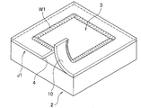
- the second metal member 3 is formed with a slit 4 extending from the outer edge toward the center.
- the placement step is a step of placing the second metal member 3 on the first metal member 2 as shown in FIG.
- the superposed portion J1 is formed by superimposing the front surface 2b of the first metal member 2 and the back surface 3c of the second metal member 3. The side surfaces of the first metal member 2 and the second metal member 3 are flush with each other.
- the friction stir process is a process in which the first metal member 2 and the second metal member 3 are friction stir welded using the rotary tool F.
- the rotating tool F includes a connecting portion F1 and a stirring pin F2.
- the rotary tool F is made of, for example, tool steel.
- the connecting part F1 is a part connected to a rotating shaft (not shown) of the friction stirrer.
- the connecting portion F1 has a cylindrical shape.
- the stirring pin F2 hangs down from the connecting part F1, and is coaxial with the connecting part F1.
- the stirring pin F2 is tapered as it is separated from the connecting portion F1.
- a spiral groove is formed on the outer peripheral surface of the stirring pin F2.
- the spiral groove in order to rotate the rotary tool F to the right, the spiral groove is formed in a counterclockwise direction from the proximal end toward the distal end. In other words, the spiral groove is formed counterclockwise as viewed from above when the spiral groove is traced from the proximal end to the distal end.
- the spiral groove when rotating the rotation tool F counterclockwise, it is preferable to form the spiral groove clockwise as it goes from the proximal end to the distal end.
- the spiral groove in this case is formed clockwise when viewed from above when the spiral groove is traced from the proximal end to the distal end.
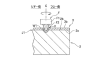
- the stirring pin F2 of the rotating tool F that rotates clockwise is inserted into the start position Sp1 set on the surface 3b of the second metal member 3, and the rotating tool F is relatively moved.
- the spiral groove of the stirring pin F2 is formed in a counterclockwise direction from the proximal end toward the distal end.
- a plasticizing region W1 is formed on the movement trajectory of the rotary tool F.
- the rotary tool F is relatively moved so that the plasticizing region W1 is a closed loop.
- the rotation tool F may be moved in any direction, but in the present embodiment, the rotation tool F is set to be counterclockwise with respect to the second metal member 3 and is rectangular in plan view along the outer edge of the second metal member 3. It is moved so that a closed loop plasticizing region W1 having a shape is formed. At that time, it is preferable to set a route so that the tip of the slit 4 is in contact with the plasticized region W1.
- the friction stir welding is performed in a state where the connecting portion F1 is not in contact with the second metal member 3, that is, in a state where the base end side of the stirring pin F2 is exposed.
- the insertion depth of the rotary tool F may be set as appropriate, but in this embodiment, the stirring pin F2 reaches the first metal member 2, that is, the first metal member 2 and the second metal member 3 are stirred. Friction stir welding is performed with the pin F2 in contact.
- the rotation tool F is arranged so that the shear side of the rotation tool F (advancing side: the side where the moving speed of the rotation tool is added to the tangential speed on the outer periphery of the rotation tool) is inside the second metal member 3.
- the movement direction and rotation direction are set.
- the rotation direction and the traveling direction of the rotary tool F are not limited to those described above, and may be set as appropriate.
- the shear side is more than the flow side of the plasticizing region W1 (retreating side: the side where the moving speed of the rotary tool is subtracted from the tangential speed on the outer periphery of the rotary tool).
- the temperature of the plastic fluidized material is likely to rise, a groove is formed on the shear side in the plasticized region W1, and a large number of burrs V tend to be generated on the shear side outside the plasticized region W1.
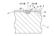
- the rotational speed of the rotary tool F is set to be high, as shown in FIGS. 4 and 5, a concave groove D is generated on the flow side in the plasticizing region W1, and the outside of the plasticizing region W1. There is a tendency that many burrs V are generated on the flow side.
- the concave groove D is a part that is deeper in the plasticized region W1. Further, by setting the rotation speed of the rotary tool F faster, the moving speed (feed speed) of the rotary tool F can be increased. Thereby, a joining cycle can be shortened.
- the side where the burr V is generated in the traveling direction of the rotary tool F depends on the joining conditions.
- the joining conditions include the rotational speed of the rotary tool F, the rotational direction, the moving direction, the moving speed (feeding speed), the inclination angle (taper angle) of the stirring pin F2, the material of the first metal member 2 and the second metal member 3. It is determined by each element such as the thickness of the second metal member 3 and a combination of these elements. If the side where the burr V is generated or the side where a lot of burr V is generated is set to be the outer edge side of the second metal member 3 according to the joining conditions, the concave groove D formed in the plasticized region W1 is also the first. Since it tends to be formed on the outer side of the bimetallic member 3, it is preferable because a removal step described later can be easily performed.
- the rotating tool F is made to make one turn and the rotating tool F is detached in the plasticizing region W1.
- the start end and the rear end of the plasticizing region W1 are overlapped.
- the removing step is a step of cutting off the surplus piece portion 10 that is a part of the second metal member 3.
- the surplus piece portion 10 is a portion of the second metal member 3 that is cut off with the plasticized region W1 as a boundary.
- the portion outside the concave groove D formed in the second metal member 3 is the surplus piece portion 10.
- the slit 4 (see also FIG. 3) is used as a starting point, and the end of the surplus piece 10 is turned up and bent and removed.
- the surplus piece portion 10 may be bent using an apparatus, but in the present embodiment, it is manually bent and excised. Thereby, the structure 1 shown in FIG. 7 is completed.
- the surface 3 b of the second metal member 3 is higher than the surface 2 b of the first metal member 2 by a plate thickness.
- the surface 3b of the second metal member 3 can be used as, for example, a part attachment site.
- the friction stir process is performed by bringing only the stirring pin F2 of the rotary tool F into contact, so that the friction stir welding is performed to a deep position without applying a large load to the friction stirrer. It can be carried out. That is, according to this embodiment, even if the plate
- the concave groove D is in the plasticized region W ⁇ b> 1 and outside the joining center line C (outside the second metal member 3). It is formed. Moreover, since the burr
- FIG. 8 is a perspective view showing a first modification of the first embodiment.
- FIG. 9 is a perspective view showing a second modification of the first embodiment.
- the planar shape of the second metal member 3 ⁇ / b> A of the first modified example is different from the first embodiment in that it is smaller than the planar shape of the first metal member 2.
- the planar shape of the second metal member 3 ⁇ / b> B of the second modification is different from that of the first embodiment in that it is larger than the planar shape of the first metal member 2.
- the joining method according to the first modification and the second modification also performs a preparation process, an arrangement process, a friction stirring process, and a removal process. Since steps other than the preparation step are the same as those in the first embodiment, description thereof is omitted. Even if the first metal member 2 and the second metal members 3A and 3B have different sizes as in the first modification and the second modification according to the first embodiment, the same effects as those of the first embodiment can be obtained. be able to. Moreover, although a specific illustration is omitted, the first metal member and the second metal member may have different shapes.
- the hollow container 1A and the method for manufacturing the hollow container according to the second embodiment of the present invention will be described.
- the second embodiment is different from the first embodiment in that a hollow container 1A having a hollow portion is manufactured.
- the preparation step is a step of preparing the hollow container body 20 and the sealing body 24 as shown in FIG.
- the hollow container body 20 includes a bottom portion 21 that has a circular shape and a peripheral wall portion 22 that rises from the outer edge of the bottom portion 21.
- the peripheral wall portion 22 has a cylindrical shape.
- a recess 23 is formed by the bottom portion 21 and the peripheral wall portion 22.
- the hollow container body 20 is formed of a metal capable of frictional stirring.
- the sealing body 24 is a thin disk-shaped metal member.
- the material of the sealing body 24 is the same as that of the hollow container body 20.
- the sealing body 24 is formed with a slit 25 extending from the outer edge toward the central portion.
- the placement step is a step of placing the sealing body 24 on the hollow container body 20 as shown in FIG.
- the end surface 22a of the peripheral wall portion 22 and the back surface 24c of the sealing body 24 are overlapped to form the overlapping portion J2.
- the outer peripheral surface of the hollow container body 20 and the outer peripheral surface of the sealing body 24 are flush with each other.
- the friction stirring step is a step of joining the hollow container body 20 and the sealing body 24 using the rotary tool F as shown in FIGS. 11 and 12.
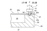
- the rotating tool F rotated to the right is inserted into the start position Sp1 shown in FIG. 11, and the rotating tool F is relatively moved along the overlapping portion J2, that is, along the outer peripheral edge of the sealing body 24.
- the rotary tool F is set so as to be counterclockwise with respect to the sealing body 24.
- frictional stirring is performed with the proximal end side of the stirring pin F2 exposed.
- the insertion depth of the stirring pin F2 may be set as appropriate, but in this embodiment, friction stir welding is performed with the stirring pin F2 in contact with the hollow container body 20 and the sealing body 24.
- burrs V are formed on the flow side (outside of the sealing body 24) outside the plasticized region W ⁇ b> 1, and recessed on the outside of the joint center line C. It is preferable to set the joining conditions so that the groove D is formed.
- the removal step is a step of cutting off the surplus piece 26 that is a part of the sealing body 24 as shown in FIG.
- the surplus piece portion 26 is a portion of the sealing body 24 that is cut off with the plasticized region W1 as a boundary.
- a portion outside the concave groove D formed in the sealing body 24 is the surplus piece portion 26.
- the slit 25 (see FIG. 11) is used as a starting point, and the end portion of the surplus piece portion 26 is turned up and bent and removed.
- the surplus piece portion 26 may be bent using an apparatus, but in the present embodiment, it is manually bent and excised. Thereby, 1 A of hollow containers provided with the hollow part inside are formed.
- the same effects as those of the first embodiment can also be obtained by the method for manufacturing a hollow container according to the second embodiment described above. Moreover, according to 2nd embodiment, the hollow container provided with the hollow part inside can be formed easily.
- the liquid cooling jacket 1 ⁇ / b> B according to the third embodiment includes a jacket body 31 and a heat sink 41.
- the jacket body 31 and the heat sink 41 are integrated by friction stir welding.
- the liquid cooling jacket 1B is an instrument for exchanging heat with a heating element (not shown) installed in the heat sink 41 by circulating a fluid such as water through an internal hollow portion.
- the jacket body 31 includes a bottom portion 32 and a peripheral wall portion 33.
- the bottom 32 has a rectangular shape in plan view.
- the peripheral wall portion 33 rises from the periphery of the bottom portion 32 and has a rectangular frame shape in plan view.
- the material of the jacket body 31 is appropriately selected from metals that can be frictionally stirred.
- the heat sink 41 includes a substrate 42, a base 43, and a plurality of fins 44.
- the substrate 42 has a rectangular plate shape in plan view.
- the base 43 is integrally formed with the substrate 42 and has a rectangular shape in plan view.
- the base 43 is formed slightly smaller than the substrate 42.
- the fins 44 extend from the base portion 43 and are arranged in parallel at a predetermined interval.
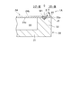
- a plasticized region W ⁇ b> 1 is formed on the outer peripheral edge of the substrate 42 and the end surface 33 a of the peripheral wall portion 33.
- the manufacturing method of the liquid cooling jacket includes a preparation process, an arrangement process, a friction stirring process, and a removal process.
- a jacket body forming process for forming the jacket body 31 and a heat sink forming process for forming the heat sink 41 are performed.
- the member to be cut 51 is cut using a multi-cutter M.
- the multi-cutter M is a rotary tool that cuts a member.
- the multi-cutter M is composed of a shaft part M1 and a plurality of disk cutters M2 arranged in parallel with the shaft part M1.
- a cutting blade (not shown) is formed on the outer peripheral edge of the disk cutter M2.
- the workpiece 51 includes a rectangular plate-like substrate 42 and a rectangular parallelepiped block 52.
- the member 51 to be cut is made of a metal capable of frictional stirring.
- the substrate 42 and the block to be cut 52 are integrally formed.
- the planar shape of the block 52 to be cut is slightly smaller than the planar shape of the substrate 42.
- the block 52 to be cut is formed at the center of the substrate 42.
- the fins 44 are formed by cutting a part of the block 52 to be cut using the multi-cutter M.
- the side 52a of the block 52 to be cut and the shaft M1 of the multi-cutter M are arranged in parallel, and the disk cutter M2 of the multi-cutter M that has been rotated is inserted into the block 52 to be cut.
- the disk cutter M2 reaches a predetermined depth, the multi-cutter M is translated to the other side 52b opposite to the side 52a.
- the shaft portion M1 reaches the side portion 52b, the multi-cutter M is relatively moved in a direction away from the block 52 to be cut.
- the insertion depth of the multi-cutter M may be set as appropriate.
- the insertion depth of the multi-cutter M is adjusted so that the disk cutter M2 does not reach the substrate 42, that is, an uncut region is formed in the block 52 to be cut. To do.
- a base portion 43 is formed between the substrate 42 and the fins 44.
- a slit 45 extending from the outer edge of the substrate 42 to the center is formed.
- a jacket body 31 having a bottom 32 and a peripheral wall 33 is formed in the jacket body forming step.
- a concave portion 34 including a bottom portion 32 and a peripheral wall portion 33 is formed inside the jacket main body 31.
- the planar shape of the recess 34 is slightly larger than the block 52 to be cut. Further, the depth of the recess 34 is larger than the height of the block 52 to be cut.
- the placement step is a step of placing the heat sink 41 on the jacket body 31.
- the back surface 42 c of the substrate 42 is overlapped with the end surface 33 a of the peripheral wall portion 33.
- the overlapping portion J3 is formed.
- the overlapping portion J3 is formed around the recess 34 and has a rectangular frame shape.
- the friction stirring step is a step of joining the jacket main body 31 and the heat sink 41 using the rotary tool F.
- the rotating tool F rotated to the right is inserted into the surface 42b of the substrate 42, and the rotating tool F is moved relative to the concave portion 34 while being rotated counterclockwise along the outer peripheral edge of the substrate 42.
- friction stir is performed with the proximal end side of the stirring pin F2 exposed.
- the insertion depth of the stirring pin F2 may be set as appropriate, but in this embodiment, friction stir welding is performed with the stirring pin F2 in contact with the jacket body 31 and the heat sink 41.
- burrs V are formed on the flow side (outside of the substrate 42) outside the plasticized region W ⁇ b> 1, and concave grooves D are formed outside the bonding center line C. It is preferable to set the joining conditions as described above.
- the removal step is a step of cutting off the surplus piece portion 50 which is a part of the substrate 42 as shown in FIG.
- the surplus piece portion 50 is a portion of the substrate 42 that is cut off with the plasticized region W1 as a boundary. In the present embodiment, a portion outside the concave groove D formed in the substrate 42 is the surplus piece portion 50.
- the slit 45 (see FIG. 17) is used as a starting point, and the end of the surplus piece 50 is turned up and removed by bending.
- the surplus piece 50 may be bent using an apparatus, but in the present embodiment, it is bent and cut manually. Thereby, the liquid cooling jacket 1B shown in FIGS. 14 and 15 is formed.
- the friction stir process is performed by bringing only the stirring pin F2 of the rotary tool F into contact, so that the friction stir welding is performed to a deep position without applying a large load to the friction stirrer. It can be carried out. That is, according to the present embodiment, bonding is possible even if the thickness of the substrate 42 of the heat sink 41 is large.
- the width of the plasticized region W1 can be reduced as compared with the case where the shoulder portion of the rotary tool is brought into contact with the substrate 42. Therefore, the width of the peripheral wall portion 33 (of the overlapping portion J3) The overlap allowance) can be reduced.
- the degree of freedom in design can be increased.
- flash V can be easily excised by setting joining conditions so that the burr
- the concave groove D is formed in the plasticized region W1 and outside the bonding center line C (the front end side of the substrate 42). Further, since the burrs V are formed outside the plasticized region W1 and outside the bonding center line C, the burrs V can be efficiently cut out together with the surplus piece 50. Moreover, since the surplus piece part 50 to cut off can be made small by this and a junction part (plasticization area
- the watertightness and confidentiality can be improved by making the rotating tool F make a round along the overlapping portion J3 and overlapping the start end and the end of the plasticized region W1.
- the base 43 of the heat sink 41 may not be provided, but the strength of the heat sink 41 can be increased by providing the base 43.
- the traveling direction and the rotation direction of the rotary tool F are set so that the shear side of the rotary tool F is the central side of the second metal member 3, the sealing body 24 or the heat sink 41.
- the rotary tool F is used.
- the friction stirring step may be performed using a rotary tool (not shown) provided with a shoulder portion and a stirring pin.
- the liquid cooling jacket 101 is a metal container having a hollow portion.
- the liquid cooling jacket 101 includes a jacket body 102 and a sealing body 103.
- the jacket main body 102 and the sealing body 103 are integrated by friction stir welding.
- a heating element (not shown) is installed on one surface of the liquid cooling jacket 101 (the surface 121a of the base 121).
- the liquid cooling jacket 101 can cool the heating element by circulating a fluid such as water, for example.
- the manufacturing method of the liquid cooling jacket which concerns on 4th embodiment performs a preparatory process, an arrangement
- the preparation process is a process of forming the jacket main body 102 and the sealing body 103.
- the jacket main body 102 is a box-shaped member whose upper side is opened.
- the jacket main body 102 is appropriately selected from metals capable of friction stirring such as aluminum, aluminum alloy, copper, copper alloy, titanium, titanium alloy, magnesium alloy, and magnesium alloy.
- the jacket main body 102 includes a bottom portion 111 having a plate shape and a peripheral wall portion 112 that rises from the periphery of the bottom portion 111.
- the peripheral wall 112 has a rectangular frame shape in plan view.
- a recess 113 is formed by the bottom 111 and the peripheral wall 112.
- the sealing body 103 is a member that seals the opening of the jacket main body 102.
- the sealing body 103 is appropriately selected from metals that can be frictionally stirred.
- the sealing body 103 is formed of the same material as that of the jacket main body 102.
- the sealing body 103 includes a base part 121 and a flange part 122.
- the base 121 has a rectangular parallelepiped shape.
- the outer peripheral edge of the base portion 121 has the same size as the inner peripheral edge of the peripheral wall portion 112.
- the flange portion 122 projects toward the side from a position lower than the surface 121a of the base portion 121 by one step.
- the flange portion 122 is formed over the entire circumference of the base portion 121.
- the plate thickness of the flange portion 122 is constant.
- the back surface 122b of the flange part 122 and the back surface 121b of the base part 121 are flush with each other (see FIG. 22A).
- the placement step is a step of placing the sealing body 103 on the jacket main body 102 as shown in FIG.
- the end surface 112a of the peripheral wall portion 112 and the back surface 122b of the flange portion 122 of the sealing body 103 are overlapped to form the overlapping portion J11.
- the side surface 112c of the peripheral wall portion 112 and the side surface 122c of the flange portion 122 are flush with each other.
- the friction stir step is a step in which the jacket main body 102 and the sealing body 103 are friction stir welded using the rotary tool G as shown in FIG.
- the rotary tool G includes a shoulder portion G1 and a stirring pin G2 that hangs down from the lower end surface G1a of the shoulder portion G1.
- the shoulder portion G1 has a cylindrical shape.
- the stirring pin G2 is tapered, and a spiral groove is formed on the outer peripheral surface.
- the stirring pin G2 of the rotating tool G that rotates counterclockwise is inserted into the start position Sp set on the surface 122a of the flange portion 122, and along the overlapping portion J11. That is, the rotary tool G is relatively moved along the flange portion 122.
- the spiral groove of the stirring pin G2 is formed clockwise as it goes from the proximal end to the distal end in order to rotate the rotary tool G counterclockwise. In other words, when the spiral groove is traced from the proximal end to the distal end, the spiral groove is formed clockwise when viewed from above.
- the spiral groove when rotating the rotation tool G to the right, it is preferable to form the spiral groove counterclockwise from the proximal end toward the distal end.
- the spiral groove in this case is formed counterclockwise as viewed from above when the spiral groove is traced from the base end to the tip end.
- the friction stir welding is performed in a state where the shoulder portion G1 is not in contact with the flange portion 122, that is, the base end side of the stirring pin G2 is exposed.
- the insertion depth of the rotary tool G may be set as appropriate, but in this embodiment, the stirring pin G2 reaches the jacket body 102, that is, the jacket body 102 and the sealing body 103 are in contact with the stirring pin G2.
- friction stir welding is performed.
- a plasticized region W11 is formed in the movement locus of the rotary tool G.
- the lower end surface G1a of the shoulder portion G1 is set at a position lower than the surface 121a of the base portion 121.
- the outer peripheral surface of the shoulder portion G1 is brought close to the side surface 121c of the base portion 121.
- a narrow space is formed by the surface 122a of the flange portion 122, the side surface 121c of the base portion 121, and the lower end surface G1a of the shoulder portion G1.
- the moving direction of the rotating tool G is such that the shear side of the rotating tool G (advancing side: the side where the moving speed of the rotating tool is added to the tangential speed on the outer periphery of the rotating tool) is the base portion 121 side.
- the direction of rotation is set.
- the rotation direction and the traveling direction of the rotary tool G are not limited to those described above, and may be set as appropriate.
- the joining conditions include the rotational speed of the rotary tool G, the rotational direction, the moving direction, the moving speed (feeding speed), the inclination angle (taper angle) of the stirring pin G2, the material of the jacket main body 102 and the sealing body 103, and the flange portion. It is determined by each element such as the thickness of 122 and a combination of these elements. If the side where the burr V is generated or the side where a lot of burr V is generated is set to the outside (tip side) of the flange portion 122 according to the joining condition, the concave groove D formed in the plasticized region W11 is also formed. Since there exists a tendency which is formed in the outer side of the flange part 122, since the removal process mentioned later can be performed easily, it is preferable.
- the rotating tool G in the friction stirring step, the rotating tool G is caused to make a round along the flange portion 122, and the rotating tool G is detached in the plasticizing region W11.
- the start end and the rear end of the plasticizing region W11 are overlapped.
- the removing step is a step of cutting off the surplus piece portion 130 which is a part of the flange portion 122, as shown in FIG.
- the surplus piece portion 130 is a portion of the flange portion 122 that is cut off with the plasticized region W11 as a boundary.
- a portion outside the concave groove D of the flange portion 122 is used as the surplus piece portion 130.
- the surplus piece 130 may be bent using an apparatus, but in the present embodiment, it is manually bent and cut off. Thereby, the liquid cooling jacket 101 shown in FIG. 20 is completed.
- the friction stir process is performed by bringing only the stirring pin G2 of the rotary tool G into contact, so that friction stir welding is performed to a deep position without applying a large load to the friction stirrer. It can be carried out. That is, according to this embodiment, even if the plate
- the width of the plasticized region W11 can be reduced as compared with the case where the shoulder portion G1 of the rotary tool G is brought into contact with the sealing body 103. Therefore, the width of the flange portion 122 ( The overhang length) can be reduced.
- variety of the flange part 122 can be raised.
- flash V can be easily excised by setting joining conditions so that the burr
- the shoulder portion since the friction stir welding is performed in a narrow closed space formed by the surface 122a of the flange portion 122, the side surface 121c of the base portion 121, and the lower end surface G1a of the shoulder portion G1, the shoulder portion It is possible to prevent the burrs V from scattering between the lower end surface G1a of the G1 and the side surface 121c of the base portion 121.
- the concave groove D is formed in the plasticized region W11 and on the outer side of the joining center line C (the front end side of the flange portion 122).
- flash V is formed in the outer side of the plasticization area
- FIG. this makes it possible to reduce the excess piece portion 130 to be excised, and to leave a large portion of the joint (plasticized region W11), so that the joint strength can be increased.
- the surplus piece portion 130 can be easily bent by the concave groove D, and the joined portion (plasticized region W11) can be finished finely without performing a burr removing operation separately.
- the plasticized region W11 is not formed on the surface 121a of the base portion 121.
- the surface 121a of the base portion 121 functions as an installation surface on which a heating element (not shown) is installed, or functions as an attachment surface to a structure. Since the plasticizing region is not formed on these installation surfaces or attachment surfaces, the properties of the installation surfaces or attachment surfaces can be made uniform. Moreover, the surface treatment process with respect to an installation surface or an attachment surface can be skipped.
- the watertightness and confidentiality can be improved by making the rotary tool G make a round along the overlapping portion J11 and overlapping the start end and the end of the plasticizing region W11.
- the liquid cooling jacket 101A and the liquid cooling jacket manufacturing method according to the fifth embodiment of the present invention will be described.
- the fifth embodiment differs from the fourth embodiment in that a support portion 114 is formed on the jacket body 102A.
- symbol is attached
- the liquid cooling jacket 101A includes a jacket main body 102A and a sealing body 103A.
- the jacket main body 102 ⁇ / b> A includes a bottom portion 111, a peripheral wall portion 112, a support portion 114, and projecting portions 115 and 115.
- the support portion 114 is a plate-like portion that rises from the bottom portion 111.
- the support portion 114 is continuously formed on one wall portion of the peripheral wall portion 112.
- the end surface 114 a of the support portion 114 is flush with the end surface 112 a of the peripheral wall portion 112. Note that the support portion 114 may be separated from the peripheral wall portion 112.
- the protruding portion 115 is a portion protruding from the end surface 114 a of the support portion 114.
- the shape of the protrusion 115 is not particularly limited, in the present embodiment, it has a cylindrical shape.
- the height dimension of the protrusion 115 is smaller than the plate thickness of the sealing body 103A.
- holes 123 and 123 that open to the back surface 121b side (see FIG. 25A) are formed.
- the hole 123 is formed at a position corresponding to the protrusions 115 and 115.
- the hollow portion of the hole portion 123 is formed by a cylindrical side wall and a bottom surface.
- the hole part 123 is a part into which the protruding part 115 is inserted.
- the size of the hole 123 is such that the protruding portion 115 is inserted without a gap.
- a preparation process, an arrangement process, a friction stirring process, and a removal process are performed.
- the preparation step the jacket main body 102A and the sealing body 103A are formed.
- the placement step is a step of inserting the protrusion 115 into the hole 123 while placing the sealing body 103A on the jacket main body 102A, as shown in FIG.
- the overlapping portion J11 is formed by the end surface 112a of the peripheral wall portion 112 and the back surface 122b of the flange portion 122, and the end surface of the protruding portion 115 and the bottom surface of the hole portion 123 are abutted to form the abutting portion J12.
- the butting portion J12 has a circular shape in plan view.
- the end surface 114a of the support portion 114 and the back surface 121b of the base portion 121 are also overlapped.
- the friction stir step is a step in which the jacket main body 102A and the sealing body 103A are friction stir welded using the rotary tool G, as shown in FIG.
- friction stir welding is performed on the overlapping portion J1 and the butt portion J12. Since the overlapping portion J11 is the same as that of the fourth embodiment, the description thereof is omitted.
- the stirring pin G2 of the rotated rotating tool G is inserted into the start position Sp set on the surface 121a of the base 121, and the rotating tool G is linearly passed through the abutting portions J12 and J12. Move.
- the insertion depth of the rotary tool G is set to such an extent that the stirring pin G2 reaches the protrusion 115.
- a plasticized region W12 is formed in the movement locus of the rotary tool G.
- the friction stir welding may be performed first in either the overlapping portion J11 or the butting portion J12.
- the friction stir welding may be performed while pushing the shoulder portion G1 into the base portion 121.
- the insertion depth of the agitation pin G2 may be set so that the agitation pin G2 reaches the support portion 114 during the friction agitation welding of the butt portion J12.
- the surplus piece portion 130 outside the flange portion 122 is cut out together with the burr V with the concave groove D formed in the plasticized region W11 as a boundary.
- the liquid cooling jacket 101A is completed.
- the joining strength of 101 A of liquid cooling jackets can be raised by carrying out friction stir welding of the butt
- the traveling direction and the rotation direction of the rotary tool G are set so that the shear side of the rotary tool G is the base part 121 side, but the flow side is set to be the base part 121 side. May be. Further, the lower end face G1a of the shoulder part G1 may be positioned above the surface 121a of the base part 121.
- the rotary tool G is used, but the friction stirring step may be performed using a shoulderless rotary tool (not shown) that does not include the shoulder portion G1.
- FIG. 26 A joining method according to a sixth embodiment of the present invention will be described with reference to the drawings.
- the joining method according to the present embodiment joins the wall member 210 and the tubular member 220 by friction stirring.
- a preparation process, an arrangement process, a joining process, and a removing process are performed.
- front surface means a surface opposite to the “back surface”.
- the preparation step is a step of preparing the wall member 210 and the cylindrical member 220.
- the wall member 210 is a plate-like member provided with a through hole 211 having a circular shape in plan view.
- the wall member 210 is made of an aluminum alloy in this embodiment.
- the material of the wall member 210 is appropriately selected from metals capable of friction stirring such as aluminum, aluminum alloy, copper, copper alloy, titanium, titanium alloy, magnesium, magnesium alloy, and the like.
- the cylindrical member 220 includes a cylindrical part 221 and a flange part 222.
- the cylindrical member 220 may be any metal that can be frictionally stirred, but is formed of the same metal as the wall member 210 in the present embodiment.
- the cylinder part 221 has a cylindrical shape.
- the outer diameter of the cylindrical portion 221 is substantially the same as the inner diameter of the through hole 211.
- the flange portion 222 projects outwardly from the tube portion 221 at the end of the tube portion 221 and has a plate shape.
- the placement step is a step of placing the cylindrical member 220 on the wall member 210 as shown in FIG.
- the cylindrical portion 221 of the cylindrical member 220 is inserted into the through-hole 211 of the wall member 210, and the overlapping portion J21 is formed by superimposing the surface 210a of the wall member 210 and the surface 222a of the flange portion 222. .
- the overlapping portion J21 is formed in a ring shape around the through hole 211.
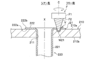
- the joining step is a step of friction stir welding the overlapping portion J21 using the rotary tool F as shown in FIGS.
- the rotary tool F includes a connecting portion F1 and a stirring pin F2.
- the spiral groove is formed in a counterclockwise direction from the proximal end toward the distal end.
- the spiral groove clockwise as it goes from the proximal end to the distal end.
- the metal plastically fluidized during friction stirring is guided to the tip side of the stirring pin F2 by the spiral groove. Thereby, the quantity of the metal which overflows outside the to-be-joined metal member (the wall member 210 and the cylindrical member 220) can be reduced.
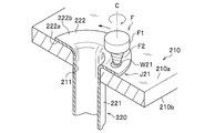
- the rotating tool F rotated to the right is inserted into the back surface 222b of the flange portion 222, and is joined along the overlapping portion J21 (along the outer peripheral edge of the flange portion 222) to join the overlapping portion J21.
- the friction stir welding is performed in a state where the connecting portion F1 is not in contact with the flange portion 222, that is, in a state where the proximal end side of the stirring pin F2 is exposed. That is, in this embodiment, the insertion depth of the rotary tool F is set so that the stirring pin F2 contacts both the wall member 210 and the flange portion 222.
- joining may be performed so that the stirring pin F2 does not reach the wall member 210, that is, only the stirring pin F2 is in contact with only the flange portion 222.
- the overlapping portion J21 is plastically fluidized and joined by frictional heat between the stirring pin F2 and the flange portion 222.
- a plasticized region W21 is formed in the movement locus of the rotary tool F.
- the rotary tool F is relatively moved so that the plasticized region W21 is a closed loop having a circular shape in plan view.
- the rotary tool F may be moved in any direction, in this embodiment, the rotary tool F is moved so as to be counterclockwise with respect to the central axis X.
- the moving direction of the rotating tool F is such that the shear side of the rotating tool F (advancing side: the side where the moving speed of the rotating tool is added to the tangential speed on the outer periphery of the rotating tool) is inside the flange portion 222.
- the rotation direction is set.
- the rotation direction and the traveling direction of the rotary tool F are not limited to those described above, and may be set as appropriate.
- the shear side is more than the flow side of the flange 222 (retreating side: the side where the moving speed of the rotary tool is subtracted from the tangential speed on the outer periphery of the rotary tool). Since the temperature of the plastic fluidized material is likely to rise, there is a tendency that a groove is formed on the shear side in the plasticized region W21 and a large amount of burrs V are generated on the shear side outside the plasticized region W21.
- occur
- the concave groove D is a part that is deeper in the plasticized region W21.
- the joining conditions include the rotational speed of the rotary tool F, the rotational direction, the moving direction, the moving speed (feeding speed), the inclination angle (taper angle) of the stirring pin F2, the material of the wall member 210 and the cylindrical member 220, and the wall member. It is determined by each element such as the thickness of 210 and the flange portion 222 and a combination of these elements.
- the concave groove D formed in the plasticized region W21 is also the flange portion 222. Since the removal process mentioned later can be performed easily, it is preferable.
- the rotating tool F is caused to make a round and the rotating tool F is detached in the plasticizing region W21.
- the start end and the rear end of the plasticized region W21 are overlapped.
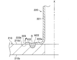
- the removal step is a step of cutting off the excess piece portion 223 that is a part of the flange portion 222 as shown in FIG.
- the surplus piece part 223 is a part that is cut off at the flange part 222 with the plasticized region W21 as a boundary.
- a portion outside the concave groove D formed in the flange portion 222 is the surplus piece portion 223.
- the end of the surplus piece 223 is turned up and removed by bending. Thereby, as shown in FIG.31 and FIG.32, the outer periphery of the flange part 222 is edged by the plasticization area
- the surplus piece 223 may be bent using an apparatus, but in the present embodiment, it is bent and cut manually. As described above, the wall member 210 and the cylindrical member 220 are joined.
- the burr V can be easily removed together with the surplus piece portion 223 by bending the surplus piece portion 223 outside the flange portion 222. Further, as shown in FIGS. 31 and 32, since the outer peripheral edge of the flange portion 222 is trimmed by the plasticizing region W21, it is possible to finish it finely without performing a separate burr removal process using a cutting tool or the like. it can.
- the concave groove D is formed in the plasticized region W21 and outside the joining center line C (outside the flange portion 222). Moreover, since the burr
- friction stir welding is performed by relatively moving along the overlapping portion J21 in a state where only the stirring pin F2 is in contact with the wall member 210 and the flange portion 222, or a state in which only the stirring portion F2 is in contact with the flange portion 222 Since the friction stir welding is performed by relatively moving along the overlapping portion J21, the overlapping portion J21 at a deep position can be joined without applying a large load to the friction stirrer.
- friction stir welding is performed in a state where only the stirring pin F2 is in contact with the wall member 210 and the flange portion 222, or friction stir welding is performed in a state where only the stirring portion F2 is in contact with the flange portion 222.
- the width of the plasticized region W21 can be reduced as compared with the case where the plastic member is pushed into the wall member 210 and the flange portion 222. Thereby, even if it does not enlarge the width
- FIG. 33 is a perspective view showing a joining process of a modification according to the sixth embodiment.
- the start position Sp of the rotary tool F is set on the surface 210a of the wall member 210.
- the rotating tool F is inserted into the flange portion 222, and the rotating tool F is relatively moved along the overlapping portion J21.
- a slit 225 may be formed at the edge of the flange portion 222.
- the slit 225 extends from the edge of the flange portion 222 toward the center.
- the joining method according to the seventh embodiment of the present invention will be described.
- a preparation process, an arrangement process, a joining process, and a removing process are performed.
- the arrangement step is mainly different from that of the sixth embodiment.
- the placement step is a step of placing the tubular member 220 on the wall member 210 as shown in FIG.
- the back surface 222b of the flange portion 222 is overlapped with the front surface 210a of the wall member 210 while communicating the through hole 211 of the wall member 210 with the hollow portion of the cylindrical portion 221 of the cylindrical member 220.
- the overlap portion J22 is formed by superimposing the front surface 210a of the wall member 210 and the back surface 222b of the flange portion 222.
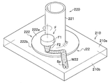
- the joining step is a step of friction stir welding the overlapping portion J22 using the rotary tool F as shown in FIGS.
- the joining step as shown in FIG. 35, after inserting the rotating tool F rotated to the left at the start position Sp set on the surface 210a of the wall member 210, the tool is plunged into the flange portion 222 along the overlapping portion J22. A round is made around the cylindrical portion 221.
- the rotation tool F in order to rotate the rotation tool F counterclockwise, the rotation tool F is relatively moved so as to be counterclockwise with respect to the cylindrical portion 221.
- a plasticized region W22 is formed in the movement locus of the rotary tool F.
- the spiral groove of the stirring pin F2 is formed to turn clockwise from the proximal end side toward the distal end side.
- the joining step friction stir welding is performed in a state where the connecting portion F1 is not in contact with the flange portion 222, that is, in a state where the proximal end side of the stirring pin F2 is exposed. That is, in this embodiment, the insertion depth of the rotary tool F is set so that the stirring pin F2 contacts both the wall member 210 and the flange portion 222.
- joining may be performed so that the stirring pin F2 does not reach the wall member 210, that is, only the stirring pin F2 is in contact with only the flange portion 222.
- the overlapping portion J22 is plastically fluidized and joined by frictional heat between the stirring pin F2 and the flange portion 222.
- the removal step is a step of cutting off the surplus piece portion 223 which is a part of the flange portion 222 as shown in FIG.
- the surplus piece 223 is a part of the flange 222 that is cut off with the plasticized region W22 as a boundary.
- a portion outside the concave groove D formed in the flange portion 222 is the surplus piece portion 223.
- the end of the surplus piece 223 is turned up and removed by bending.
- the outer peripheral edge of the flange portion 222 is edged by the plasticized region W22.
- the surplus piece 223 may be bent using an apparatus, but in the present embodiment, it is bent and cut manually.
- the wall member 210 and the cylindrical member 220 are joined.
- a slit may be provided in the flange portion 222, and the excess piece portion 223 may be removed by turning up the excess piece portion 223 starting from the slit.
- the rotating tool F may be directly inserted into the surface 222a of the flange portion 222.
- the cylindrical portion 221 is a cylinder, but may be a cylindrical shape having an elliptical cross section or a polygonal cross section.
- the through-hole 211 is also changed according to the shape of the cylinder part 221.
- the joining step may be performed in a state where the rotation center axis of the rotary tool F is inclined outward (outside with respect to the center axis X).
- the width of flange part 222 can also be made small.
- the rotary tool F is preferably attached to an arm robot having a driving unit such as a spindle unit at the tip.
- shaft of the rotation tool F can be inclined easily.
Landscapes
- Engineering & Computer Science (AREA)
- Mechanical Engineering (AREA)
- Pressure Welding/Diffusion-Bonding (AREA)
Abstract
設計の自由度が高い接合方法を提供することを課題とする。第一金属部材2の表面2bと板状の第二金属部材3の裏面3cとを重ね合せて重合部J1を形成する配置工程と、回転ツールFを第二金属部材3の表面3bから挿入し、回転ツールFの攪拌ピンF2のみを第一金属部材2及び第二金属部材3の両方に接触させた状態で回転ツールFを相対移動させて重合部J1に対して摩擦攪拌接合を行う摩擦攪拌工程と、を含み、摩擦攪拌工程では、バリVが第二金属部材3の外側に形成されるように接合条件を設定することを特徴とする。
Description
本発明は、接合方法、中空容器の製造方法及び液冷ジャケットの製造方法に関する。
特許文献1には、ジャケット本体と、当該ジャケット本体の凹部を覆う封止体とを備えた液冷ジャケットが開示されている。当該液冷ジャケットの製造方法は、樹脂性のジャケット本体と金属製の封止体とが重ね合わされた重合部に対して、封止体の表面で回転ツールを回転させ、当該回転ツールとジャケット本体との摩擦熱でジャケット本体の一部を溶融させて接合するというものである。
また、貫通孔を備えた壁部材と、前記貫通孔にフランジ部付きの筒状部材を挿入して両者を接合する接合方法が知られている(特許文献2)。当該接合方法は、壁部材の表面とフランジ部の表面とが重ね合わされた重合部を回転ツールで摩擦攪拌接合するというものである。
従来技術では、封止体の板厚が大きくなると摩擦熱が重合部に到達せず、重合部を接合することができないという問題がある。回転ツールを大きくすれば、摩擦熱を大きくすることができるが、封止体の表面にバリが多く発生するとともに、塑性化領域の凹溝も大きくなる。さらには、摩擦攪拌装置への負荷も大きくなる。すなわち、従来の液冷ジャケットの製造方法では設計の自由度が低いという問題がある。
また、従来の接合方法では、摩擦攪拌接合後にバリが発生するため、切削工具等を用いてバリを除去する作業が煩雑になるという問題がある。
このような観点から、本発明は、設計の自由度が高い接合方法、中空容器の製造方法及び液冷ジャケットの製造方法を提供することを課題とする。また、本発明は、バリを容易に除去することができる接合方法を提供することを課題とする。
このような課題を解決するために本発明は、第一金属部材の表面と板状の第二金属部材の裏面とを重ね合せて重合部を形成する配置工程と、回転ツールを前記第二金属部材の表面から挿入し、前記回転ツールの攪拌ピンのみを前記第二金属部材のみ、又は、前記第一金属部材及び前記第二金属部材の両方に接触させた状態で前記回転ツールを閉ループとなるように相対移動させて前記重合部に対して摩擦攪拌接合を行う摩擦攪拌工程と、を含み、前記摩擦攪拌工程では、バリが前記第二金属部材の外側に形成されるように接合条件を設定することを特徴とする。
また、本発明は、底部と前記底部の周縁から立ち上る周壁部とを備える中空容器本体及び板状の封止体を形成する準備工程と、前記周縁部の端面と前記封止体の裏面とを重ね合せて重合部を形成する配置工程と、前記回転ツールを前記封止体の表面から挿入し、前記回転ツールの攪拌ピンのみを前記封止体のみ、又は、前記周壁部及び前記封止体の両方に接触させた状態で前記回転ツールを相対移動させて前記重合部に対して摩擦攪拌接合を行う摩擦攪拌工程と、前記摩擦攪拌工程では、バリが前記封止体の外側に形成されるように接合条件を設定することを特徴とする。
また、本発明は、底部と前記底部の周縁から立ち上る周壁部とを備えるジャケット本体を形成するとともに、基板と複数のフィンとを備えるヒートシンクを形成する準備工程と、前記周壁部の端面と前記基板の裏面とを重ね合せて重合部を形成する配置工程と、回転ツールを前記基板の表面から挿入し、前記回転ツールの攪拌ピンのみを前記基板のみ、又は、前記基板及び周壁部の両方に接触させた状態で前記回転ツールを相対移動させて前記重合部に対して摩擦攪拌接合を行う摩擦攪拌工程と、を含み、前記摩擦攪拌工程では、バリが前記ヒートシンクの外側に形成されるように接合条件を設定することを特徴とする。
かかる方法によれば、回転ツールの攪拌ピンのみを接触させて摩擦攪拌工程を行うので、摩擦攪拌装置に大きな負荷をかけずに、深い位置まで摩擦攪拌接合を行うことができる。つまり、本発明によれば、第二金属部材、封止体又はヒートシンクの板厚が大きくても接合可能となるため、設計の自由度を高めることができる。また、摩擦攪拌接合によって発生するバリを第二金属部材、封止体又はヒートシンクの外側に形成させることができるため、バリを容易に除去することができる。
また、前記摩擦攪拌工程において、塑性化領域内に形成された凹溝を境にして、前記第二金属部材、封止体又はヒートシンクの外側の余剰片部をバリとともに切除する除去工程と、をさらに含むことが好ましい。かかる方法によれば、バリを余剰片部ごと除去することができる。
また、本発明は、底部と前記底部の周縁から立ち上る周壁部とを備えるジャケット本体を形成するとともに、基体部と前記基体部の表面とは一段下がった位置から側方に張り出すフランジ部とを備える封止体を形成する準備工程と、前記周壁部の端面と前記フランジ部の裏面とを重ね合せて重合部を形成する配置工程と、回転ツールを前記フランジ部の表面から挿入し、前記回転ツールの攪拌ピンのみを前記フランジ部のみ、又は、前記周壁部及び前記フランジ部の両方に接触させた状態で前記フランジ部に沿って前記回転ツールを相対移動させて前記重合部に対して摩擦攪拌接合を行う摩擦攪拌工程と、を含み、前記摩擦攪拌工程では、バリが前記フランジ部の外側に形成されるように接合条件を設定することを特徴とする。
かかる方法によれば、回転ツールの攪拌ピンのみを接触させて摩擦攪拌工程を行うので、摩擦攪拌装置に大きな負荷をかけずに、深い位置まで摩擦攪拌接合を行うことができる。つまり、本発明によれば、封止体の板厚が大きくても接合可能となる。また、回転ツールのショルダ部を封止体に当接させる場合に比べて、塑性化領域の幅を小さくできるので、フランジ部の幅(張り出し長さ)を小さくすることができる。このように、本発明によれば、封止体の板厚及びフランジ部の幅の設計の自由度を高めることができる。また、摩擦攪拌接合によって発生するバリをフランジ部の外側に形成させることができるため、バリを容易に除去することができる。
また、前記摩擦攪拌工程において塑性化領域内に形成された凹溝を境にして、前記フランジ部の外側の余剰片部をバリとともに切除する除去工程をさらに含むことが好ましい。かかる方法によれば、バリを余剰片部ごと除去することができる。
また、前記摩擦攪拌工程では、ショルダ部と攪拌ピンとを備える回転ツールを使用し、前記ショルダ部の下端面を前記基体部の表面より低い位置に設定して摩擦攪拌接合を行うことが好ましい。
かかる方法によれば、ショルダ部の下端面と基体部の側面との間からバリが飛散するのを防ぐことができる。
また、前記準備工程では、前記ジャケット本体の前記底部から立ち上る支持部と、前記支持部から突出する突出部とを形成するとともに、前記封止体に前記突出部が挿入される孔部を形成し、前記配置工程では、前記周壁部の端面に前記封止体を配置するとともに、前記孔部に前記突出部を挿入し、前記摩擦攪拌工程では、前記突出部の端面と前記孔部の底面との突合せ部にも摩擦攪拌接合を行うことが好ましい。
かかる方法によれば、突合せ部に対しても摩擦攪拌接合を行うので、液冷ジャケットの接合強度を高めることができる。
また、本発明は、貫通孔を有する壁部材と、一端側にフランジ部を有する筒状部材を準備する準備工程と、前記貫通孔に前記筒状部材の他端側を挿入して前記フランジ部の表面と前記壁部材の表面とを重ね合わせて重合部を形成する配置工程と、回転ツールを前記フランジ部の裏面から挿入し、前記回転ツールの攪拌ピンのみを前記フランジ部のみ、又は前記フランジ部及び前記壁部材の両方に接触させた状態で、前記フランジ部の周縁に沿って前記回転ツールを相対移動させて前記重合部に対して摩擦攪拌接合を行う接合工程と、前記接合工程で塑性化領域内に形成された凹溝を境にして、前記フランジ部の外側の余剰片部をバリとともに切除する除去工程と、を含むことを特徴とする。
また、本発明は、貫通孔を有する壁部材と、一端側にフランジ部を有する筒状部材を準備する準備工程と、前記貫通孔に前記筒状部材の他端側を挿入して前記フランジ部の表面と前記壁部材の表面とを重ね合わせて重合部を形成する配置工程と、回転ツールを前記壁部材の表面から挿入し、前記回転ツールの攪拌ピンのみを前記フランジ部のみ、又は前記フランジ部及び前記壁部材の両方に接触させた状態で、前記フランジ部の周縁に沿って前記回転ツールを相対移動させて前記重合部に対して摩擦攪拌接合を行う接合工程と、前記接合工程で塑性化領域内に形成された凹溝を境にして、前記フランジ部の外側の余剰片部をバリとともに切除する除去工程と、を含むことを特徴とする。
また、本発明は、貫通孔を有する壁部材と、一端側にフランジ部を有する筒状部材を準備する準備工程と、前記貫通孔と前記筒状部材の中空部とを連通させつつ、前記フランジ部の裏面と前記壁部材の表面とを重ね合わせて重合部を形成する配置工程と、回転ツールを前記フランジ部の表面から挿入し、前記回転ツールの攪拌ピンのみを前記フランジ部のみ、又は前記フランジ部及び前記壁部材の両方に接触させた状態で前記フランジ部の周縁に沿って前記回転ツールを相対移動させて前記重合部に対して摩擦攪拌接合を行う接合工程と、前記接合工程で塑性化領域内に形成された凹溝を境にして、前記フランジ部の外側の余剰片部をバリとともに切除する除去工程と、を含むことを特徴とする。
また、本発明は、貫通孔を有する壁部材と、一端側にフランジ部を有する筒状部材を準備する準備工程と、前記貫通孔と前記筒状部材の中空部とを連通させつつ、前記フランジ部の裏面と前記壁部材の表面とを重ね合わせて重合部を形成する配置工程と、回転ツールを前記壁部材の表面から挿入し、前記回転ツールの攪拌ピンのみを前記フランジ部のみ、又は前記フランジ部及び前記壁部材の両方に接触させた状態で前記フランジ部の周縁に沿って前記回転ツールを相対移動させて前記重合部に対して摩擦攪拌接合を行う接合工程と、前記接合工程で塑性化領域内に形成された凹溝を境にして、前記フランジ部の外側の余剰片部をバリとともに切除する除去工程と、を含むことを特徴とする。
また、本発明は、貫通孔を有する壁部材と、一端側にフランジ部を有する筒状部材を準備する準備工程と、前記貫通孔に前記筒状部材の他端側を挿入して前記フランジ部の表面と前記壁部材の表面とを重ね合わせて重合部を形成する配置工程と、回転ツールを前記壁部材の表面から挿入し、前記回転ツールの攪拌ピンのみを前記フランジ部のみ、又は前記フランジ部及び前記壁部材の両方に接触させた状態で、前記フランジ部の周縁に沿って前記回転ツールを相対移動させて前記重合部に対して摩擦攪拌接合を行う接合工程と、前記接合工程で塑性化領域内に形成された凹溝を境にして、前記フランジ部の外側の余剰片部をバリとともに切除する除去工程と、を含むことを特徴とする。
また、本発明は、貫通孔を有する壁部材と、一端側にフランジ部を有する筒状部材を準備する準備工程と、前記貫通孔と前記筒状部材の中空部とを連通させつつ、前記フランジ部の裏面と前記壁部材の表面とを重ね合わせて重合部を形成する配置工程と、回転ツールを前記フランジ部の表面から挿入し、前記回転ツールの攪拌ピンのみを前記フランジ部のみ、又は前記フランジ部及び前記壁部材の両方に接触させた状態で前記フランジ部の周縁に沿って前記回転ツールを相対移動させて前記重合部に対して摩擦攪拌接合を行う接合工程と、前記接合工程で塑性化領域内に形成された凹溝を境にして、前記フランジ部の外側の余剰片部をバリとともに切除する除去工程と、を含むことを特徴とする。
また、本発明は、貫通孔を有する壁部材と、一端側にフランジ部を有する筒状部材を準備する準備工程と、前記貫通孔と前記筒状部材の中空部とを連通させつつ、前記フランジ部の裏面と前記壁部材の表面とを重ね合わせて重合部を形成する配置工程と、回転ツールを前記壁部材の表面から挿入し、前記回転ツールの攪拌ピンのみを前記フランジ部のみ、又は前記フランジ部及び前記壁部材の両方に接触させた状態で前記フランジ部の周縁に沿って前記回転ツールを相対移動させて前記重合部に対して摩擦攪拌接合を行う接合工程と、前記接合工程で塑性化領域内に形成された凹溝を境にして、前記フランジ部の外側の余剰片部をバリとともに切除する除去工程と、を含むことを特徴とする。
かかる接合方法によれば、フランジ部の外側の余剰片部を凹溝を境に折り曲げるなどして、バリを余剰片部ごと容易に除去することができる。
また、前記接合工程では、前記フランジ部の外側にバリが発生するように接合条件を設定することが好ましい。
かかる接合方法によれば、余剰片部にバリを集約することができるため、除去工程をより容易に行うことができる。
本発明に係る接合方法、中空容器の製造方法及び液冷ジャケットの製造方法によれば、設計の自由度を高めることができる。また、本発明に係る接合方法によれば、バリを容易に除去することができる。
[第一実施形態]
本発明の第一実施形態に係る接合方法について図面を参照して詳細に説明する。図1に示すように、本実施形態に係る接合方法は、第一金属部材2と第二金属部材3とを接合して構造物1を形成するものである。
本発明の第一実施形態に係る接合方法について図面を参照して詳細に説明する。図1に示すように、本実施形態に係る接合方法は、第一金属部材2と第二金属部材3とを接合して構造物1を形成するものである。
本実施形態に係る接合方法は、準備工程と、配置工程と、摩擦攪拌工程と、除去工程と、を行う。準備工程は、第一金属部材2及び第二金属部材3を形成する工程である。なお、説明における「表面」とは、「裏面」に対する反対側の面という意味である。
図1に示すように第一金属部材2は、板状の金属部材である。第一金属部材2は、アルミニウム、アルミニウム合金、銅、銅合金、チタン、チタン合金、マグネシウム、マグネシウム合金等の摩擦攪拌可能な金属から適宜選択される。第一金属部材2は、本実施形態では板状としているが、他の形状であってもよい。
第二金属部材3は、板状の部材である。第二金属部材3は、摩擦攪拌可能な金属から適宜選択される。第二金属部材3は、本実施形態では、第一金属部材2と同等の材料で形成されている。第二金属部材3は、第一金属部材2と同じ平面形状を呈するが、第一金属部材2よりも薄くなっている。第二金属部材3には、外縁から中央部に向けて延設されたスリット4が形成されている。
配置工程は、図2に示すように、第一金属部材2に第二金属部材3を配置する工程である。配置工程では、第一金属部材2の表面2bと、第二金属部材3の裏面3cとを重ね合せて重合部J1を形成する。第一金属部材2と第二金属部材3の各側面はそれぞれ面一になる。
摩擦攪拌工程は、第一金属部材2と第二金属部材3とを回転ツールFを用いて摩擦攪拌接合する工程である。図3及び図4に示すように、回転ツールFは、連結部F1と、攪拌ピンF2とで構成されている。回転ツールFは、例えば工具鋼で形成されている。連結部F1は、摩擦攪拌装置の回転軸(図示省略)に連結される部位である。連結部F1は円柱状を呈している。
攪拌ピンF2は、連結部F1から垂下しており、連結部F1と同軸になっている。攪拌ピンF2は連結部F1から離間するにつれて先細りになっている。攪拌ピンF2の外周面には螺旋溝が刻設されている。本実施形態では、回転ツールFを右回転させるため、螺旋溝は、基端から先端に向かうにつれて左回りに形成されている。言い換えると、螺旋溝は、螺旋溝を基端から先端に向けてなぞると上から見て左回りに形成されている。
なお、回転ツールFを左回転させる場合は、螺旋溝を基端から先端に向かうにつれて右回りに形成することが好ましい。言い換えると、この場合の螺旋溝は、螺旋溝を基端から先端に向けてなぞると上から見て右回りに形成されている。螺旋溝をこのように設定することで、摩擦攪拌の際に塑性流動化した金属が螺旋溝によって攪拌ピンF2の先端側に導かれる。これにより、被接合金属部材(第一金属部材2及び第二金属部材3)の外部に溢れ出る金属の量を少なくすることができる。螺旋溝は省略してもよい。
摩擦攪拌工程では、第二金属部材3の表面3bに設定した開始位置Sp1に、右回転する回転ツールFの攪拌ピンF2を挿入し、回転ツールFを相対移動させる。本実施形態では、回転ツールFを右回転させるため、攪拌ピンF2の螺旋溝は、基端から先端に向かうにつれて左回りに形成されている。回転ツールFの移動軌跡には塑性化領域W1が形成される。摩擦攪拌工程では、塑性化領域W1が閉ループとなるように回転ツールFを相対移動させる。回転ツールFはどちら周りに移動させてもよいが、本実施形態では、第二金属部材3に対して左回りとなるように設定するとともに、第二金属部材3の外縁に沿って平面視矩形状の閉ループの塑性化領域W1が形成されるように移動させる。その際、スリット4の先端と、塑性化領域W1とが接触するようにルートを設定することが好ましい。
摩擦攪拌工程では、図4に示すように、連結部F1を第二金属部材3に接触させない状態で、つまり、攪拌ピンF2の基端側を露出させた状態で摩擦攪拌接合を行う。回転ツールFの挿入深さは、適宜設定すればよいが、本実施形態では、攪拌ピンF2が第一金属部材2に達するように、つまり、第一金属部材2及び第二金属部材3と攪拌ピンF2とを接触させた状態で摩擦攪拌接合を行う。
なお、攪拌ピンF2が第一金属部材2に達しない場合、つまり、攪拌ピンF2を第二金属部材3のみと接触させる場合は、第二金属部材3と攪拌ピンF2との摩擦熱によって重合部J1が塑性流動化して接合される。
本実施形態では、回転ツールFのシアー側(advancing side:回転ツールの外周における接線速度に回転ツールの移動速度が加算される側)が第二金属部材3の内側となるように回転ツールFの移動方向と回転方向を設定している。回転ツールFの回転方向及び進行方向は前記したものに限定されるものではなく適宜設定すればよい。
例えば、回転ツールFの回転速度が遅い場合では、塑性化領域W1のフロー側(retreating side:回転ツールの外周における接線速度から回転ツールの移動速度が減算される側)に比べてシアー側の方が塑性流動材の温度が上昇しやすくなるため、塑性化領域W1内のシアー側に凹溝が発生し、塑性化領域W1外のシアー側にバリVが多く発生する傾向にある。一方、例えば、回転ツールFの回転速度が速い場合、シアー側の方が塑性流動材の温度が上昇するものの、回転速度が速い分、塑性化領域W1内のフロー側に凹溝が発生し、塑性化領域W1外のフロー側にバリVが多く発生する傾向にある。
本実施形態では、回転ツールFの回転速度を速く設定しているため、図4及び図5に示すように、塑性化領域W1内のフロー側に凹溝Dが発生し、塑性化領域W1外のフロー側にバリVが多く発生する傾向にある。凹溝Dは、塑性化領域W1のうち、より深くえぐれる部位である。また、回転ツールFの回転速度を速く設定することにより、回転ツールFの移動速度(送り速度)を高めることができる。これにより、接合サイクルを短くすることができる。
摩擦攪拌工程の際に、回転ツールFの進行方向のどちら側にバリVが発生するかは接合条件によって異なる。当該接合条件とは、回転ツールFの回転速度、回転方向、移動方向、移動速度(送り速度)、攪拌ピンF2の傾斜角度(テーパー角度)、第一金属部材2及び第二金属部材3の材質、第二金属部材3の厚さ等の各要素とこれらの要素の組み合わせで決定される。接合条件に応じて、バリVが発生する側又はバリVが多く発生する側が第二金属部材3の外縁側となるように設定すれば、塑性化領域W1内に形成される凹溝Dも第二金属部材3の外側に形成される傾向があるので、後記する除去工程を容易に行うことができるため好ましい。
摩擦攪拌工程では、回転ツールFを一周させて、塑性化領域W1内で回転ツールFを離脱させる。摩擦攪拌工程では、塑性化領域W1の始端と後端が重複するようにする。
除去工程は、図5及び図6に示すように、第二金属部材3の一部である余剰片部10を切除する工程である。余剰片部10とは、第二金属部材3において、塑性化領域W1を境にして切除される部位である。本実施形態では、第二金属部材3に形成されたの凹溝Dよりも外側の部位を余剰片部10としている。
除去工程では、スリット4(図3も参照)を起点として、余剰片部10の端部をめくり上げつつ、折り曲げるようにして除去する。除去工程では、装置を用いて余剰片部10を折り曲げてもよいが、本実施形態では、手作業で折り曲げて切除している。これにより、図7に示す構造物1が完成する。
図7に示すように、第二金属部材3の表面3bは、第一金属部材2の表面2bよりも板厚分高くなっている。第二金属部材3の表面3bを例えば部品の取り付け部位として利用することができる。
以上説明した液冷ジャケットの製造方法によれば、回転ツールFの攪拌ピンF2のみを接触させて摩擦攪拌工程を行うので、摩擦攪拌装置に大きな負荷をかけずに、深い位置まで摩擦攪拌接合を行うことができる。つまり、本実施形態によれば、第二金属部材3の板厚が大きくても接合可能となる。また、本実施形態のように、バリVが第二金属部材3の外側に形成されるように接合条件を設定することにより、バリVを容易に切除することができる。
また、図4及び図5に示すように、本実施形態によれば、凹溝Dは塑性化領域W1内で、かつ、接合中心線Cの外側(第二金属部材3に対して外側)に形成される。また、バリVは塑性化領域W1外で、かつ、接合中心線Cの外側に形成されるので、余剰片部10とともにバリVを効率よく切除することができる。これにより、切除する余剰片部10を小さくすることができるとともに、接合部(塑性化領域W1)を大きく残存させることができるため、接合強度を高めることができる。また、凹溝Dによって余剰片部10を容易に折り曲げることができるとともに、バリ除去作業を別途行わなくても接合部(塑性化領域W1)をきれいに仕上げることができる。
図8は、第一実施形態の第一変形例を示す斜視図である。図9は、第一実施形態の第二変形例を示す斜視図である。図8に示すように、第一変形例の第二金属部材3Aの平面形状は、第一金属部材2の平面形状よりも小さい点で第一実施形態と相違する。また、図9に示すように、第二変形例の第二金属部材3Bの平面形状は、第一金属部材2の平面形状よりも大きい点で第一実施形態と相違する。
第一変形例及び第二変形例に係る接合方法も、準備工程、配置工程、摩擦攪拌工程、除去工程を行う。準備工程以外の工程は第一実施形態と同じであるため説明を省略する。第一実施形態に係る第一変形例及び第二変形例のように、第一金属部材2と第二金属部材3A,3Bとが異なる大きさであっても第一実施形態と同じ効果を奏することができる。また、具体的な図示は省略するが、第一金属部材と第二金属部材とが異なる形状であってもよい。
[第二実施形態]
次に、本発明の第二実施形態に係る中空容器1A及び中空容器の製造方法について説明する。図10に示すように、第二実施形態では、中空部を備えた中空容器1Aを製造する点で第一実施形態と相違する。
次に、本発明の第二実施形態に係る中空容器1A及び中空容器の製造方法について説明する。図10に示すように、第二実施形態では、中空部を備えた中空容器1Aを製造する点で第一実施形態と相違する。
第二実施形態に係る中空容器の製造方法では、準備工程と、配置工程と、摩擦攪拌工程と、除去工程とを行う。準備工程は、図10に示すように、中空容器本体20と封止体24とを準備する工程である。中空容器本体20は、円形を呈する底部21と、底部21の外縁から立ち上る周壁部22とで構成されている。周壁部22は円筒状を呈する。底部21及び周壁部22とで凹部23が形成されている。中空容器本体20は、摩擦攪拌可能な金属で形成されている。
封止体24は、薄い円板状の金属部材である。封止体24の材料は、中空容器本体20と同等である。封止体24には、外縁から中央部に向けて延設されたスリット25が形成されている。
配置工程は、図11に示すように、中空容器本体20に封止体24を配置する工程である。配置工程では、周壁部22の端面22aと封止体24の裏面24cとを重ね合せて重合部J2を形成する。中空容器本体20の外周面と、封止体24の外周面とは面一になる。
摩擦攪拌工程は、図11及び図12に示すように、回転ツールFを用いて中空容器本体20と封止体24とを接合する工程である。摩擦攪拌工程では、図11に示す開始位置Sp1に右回転させた回転ツールFを挿入し、重合部J2に沿って、つまり、封止体24の外周縁に沿って回転ツールFを相対移動せる。回転ツールFは、封止体24に対して左回りとなるように設定する。図12に示すように、第一実施形態と同様に攪拌ピンF2の基端側は露出させた状態で摩擦攪拌を行う。攪拌ピンF2の挿入深さは適宜設定すればよいが、本実施形態では、攪拌ピンF2を中空容器本体20及び封止体24に接触させた状態で摩擦攪拌接合を行う。また、第一実施形態と同様に、図13に示すように、塑性化領域W1外においてフロー側(封止体24の外側)にバリVが形成されるとともに、接合中心線Cの外側に凹溝Dが形成されるように接合条件を設定することが好ましい。
除去工程は、図13に示すように、封止体24の一部である余剰片部26を切除する工程である。余剰片部26とは、封止体24において、塑性化領域W1を境にして切除されう部位である。本実施形態では、封止体24に形成された凹溝Dよりも外側の部位を余剰片部26としている。
除去工程では、スリット25(図11参照)を起点として、余剰片部26の端部をめくり上げつつ、折り曲げるようにして除去する。除去工程では、装置を用いて余剰片部26を折り曲げてもよいが、本実施形態では、手作業で折り曲げて切除している。これにより、内部に中空部を備えた中空容器1Aが形成される。
以上説明した第二実施形態に係る中空容器の製造方法によっても、第一実施形態と同様の効果を奏することができる。また、第二実施形態によれば、内部に中空部を備えた中空容器を容易に形成することができる。
[第三実施形態]
次に、第三実施形態に係る液冷ジャケットの製造方法及び液冷ジャケットについて説明する。図14に示すように、第三実施形態に係る液冷ジャケット1Bは、ジャケット本体31と、ヒートシンク41とで構成されている。ジャケット本体31とヒートシンク41とは摩擦攪拌接合により一体化されている。液冷ジャケット1Bは、内部の中空部に例えば水などの流体を流通させることにより、ヒートシンク41に設置された発熱体(図示省略)と熱交換を行うための器具である。
次に、第三実施形態に係る液冷ジャケットの製造方法及び液冷ジャケットについて説明する。図14に示すように、第三実施形態に係る液冷ジャケット1Bは、ジャケット本体31と、ヒートシンク41とで構成されている。ジャケット本体31とヒートシンク41とは摩擦攪拌接合により一体化されている。液冷ジャケット1Bは、内部の中空部に例えば水などの流体を流通させることにより、ヒートシンク41に設置された発熱体(図示省略)と熱交換を行うための器具である。
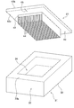
図15に示すように、ジャケット本体31は、底部32と、周壁部33とで構成されている。底部32は平面視矩形を呈する。周壁部33は、底部32の周縁から立ち上り、平面視矩形枠状を呈する。ジャケット本体31の材料は、摩擦攪拌可能な金属から適宜選択される。
ヒートシンク41は、基板42と、基部43と、複数のフィン44とで構成されている。基板42は、平面視矩形の板状を呈する。基部43は、基板42と一体形成されており、平面視矩形を呈する。基部43は、基板42よりも一回り小さく形成されている。フィン44は、基部43から延設されており、所定の間隔をあけて並設されている。基板42の外周縁と周壁部33の端面33aには塑性化領域W1が形成されている。
液冷ジャケットの製造方法は、準備工程と、配置工程と、摩擦攪拌工程と、除去工程とを行う。準備工程は、ジャケット本体31を形成するジャケット本体形成工程と、ヒートシンク41を形成するヒートシンク形成工程を行う。図16に示すように、ヒートシンク形成工程では、マルチカッターMを用いて被切削部材51を切削する。
マルチカッターMは、部材を切削する回転工具である。マルチカッターMは、軸部M1と、軸部M1に間をあけて並設された複数の円盤カッターM2とで構成されている。円盤カッターM2の外周縁には切削刃(図示省略)が形成されている。円盤カッターM2の板厚及び間隔を調節することにより、フィン44の間隔及び板厚を適宜設定することができる。
被切削部材51は、矩形板状の基板42と、直方体の被切削ブロック52とで構成されている。被切削部材51は、摩擦攪拌可能な金属で形成されている。基板42と被切削ブロック52とは一体形成されている。被切削ブロック52の平面形状は、基板42の平面形状よりも一回り小さくなっている。被切削ブロック52は、基板42の中央に形成されている。
ヒートシンク形成工程では、マルチカッターMを用いて被切削ブロック52の一部を切削してフィン44(図17参照)を形成する。ヒートシンク形成工程では、被切削ブロック52の辺部52aとマルチカッターMの軸部M1とが平行となるように配置して、回転させたマルチカッターMの円盤カッターM2を被切削ブロック52に挿入する。円盤カッターM2が所定の深さに達したら、辺部52aと対向する他方の辺部52bまでマルチカッターMを平行移動させる。軸部M1が辺部52bに達したらマルチカッターMを被切削ブロック52から離間する方向に相対移動させる。
マルチカッターMの挿入深さは、適宜設定すればよいが、本実施形態では、円盤カッターM2が基板42に達しないように、つまり、被切削ブロック52に未切削領域が形成されるように調節する。これにより、図17に示すように、基板42とフィン44との間に基部43が形成される。また、ヒートシンク形成工程では、基板42の外縁から中央部に延設するスリット45を形成する。
図17に示すように、ジャケット本体形成工程では、底部32と周壁部33とを有するジャケット本体31を形成する。ジャケット本体31の内部には、底部32と周壁部33とで構成される凹部34が形成される。凹部34の平面形状は、被切削ブロック52よりも一回り大きくなっている。また、凹部34の深さは、被切削ブロック52の高さよりも大きくなっている。
配置工程は、ジャケット本体31にヒートシンク41を配置する工程である。配置工程では、図17に示すように、周壁部33の端面33aに基板42の裏面42cを重ね合せる。これにより、図18に示すように重合部J3が形成される。重合部J3は凹部34の周囲に形成され、矩形枠状を呈する。
摩擦攪拌工程は、回転ツールFを用いてジャケット本体31とヒートシンク41とを接合する工程である。摩擦攪拌工程では、基板42の表面42bに右回転させた回転ツールFを挿入し、基板42の外周縁に沿わせつつ凹部34に対して左回りとなるように回転ツールFを相対移動せる。
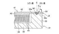
図18に示すように、第一実施形態と同様に攪拌ピンF2の基端側は露出させた状態で摩擦攪拌を行う。攪拌ピンF2の挿入深さは適宜設定すればよいが、本実施形態では、攪拌ピンF2をジャケット本体31及びヒートシンク41に接触させた状態で摩擦攪拌接合を行う。図19に示すように、第一実施形態と同様に、塑性化領域W1外においてフロー側(基板42の外側)にバリVが形成されるとともに、接合中心線Cの外側に凹溝Dが形成されるように接合条件を設定することが好ましい。
除去工程は、図19に示すように、基板42の一部である余剰片部50を切除する工程である。余剰片部50とは、基板42において、塑性化領域W1を境にして切除される部位である。本実施形態では、基板42に形成された凹溝Dよりも外側の部位を余剰片部50としている。
除去工程では、スリット45(図17参照)を起点として、余剰片部50の端部をめくり上げつつ、折り曲げるようにして除去する。除去工程では、装置を用いて余剰片部50を折り曲げてもよいが、本実施形態では、手作業で折り曲げて切除している。これにより、図14,15に示す液冷ジャケット1Bが形成される。
以上説明した液冷ジャケットの製造方法によれば、回転ツールFの攪拌ピンF2のみを接触させて摩擦攪拌工程を行うので、摩擦攪拌装置に大きな負荷をかけずに、深い位置まで摩擦攪拌接合を行うことができる。つまり、本実施形態によれば、ヒートシンク41の基板42の板厚が大きくても接合可能となる。また、本実施形態によれば、回転ツールのショルダ部を基板42に当接させる場合に比べて、塑性化領域W1の幅を小さくすることができるため、周壁部33の幅(重合部J3の重ね代)を小さくすることができる。このように、本実施形態によれば、設計の自由度を高めることができる。また、本実施形態のように、バリVが基板42の外側に形成されるように接合条件を設定することにより、バリVを容易に切除することができる。
また、図19に示すように、本実施形態によれば、凹溝Dは塑性化領域W1内で、かつ、接合中心線Cの外側(基板42の先端側)に形成される。また、バリVは塑性化領域W1外で、かつ、接合中心線Cの外側に形成されるので、余剰片部50とともにバリVを効率よく切除することができる。また、これにより、切除する余剰片部50を小さくすることができるとともに、接合部(塑性化領域W1)を大きく残存させることができるため、接合強度を高めることができる。また、除去工程では、凹溝Dによって余剰片部50を容易に折り曲げることができるとともに、バリ除去作業を別途行わなくても接合部(塑性化領域W1)をきれいに仕上げることができる。
また、本実施形態の摩擦攪拌工程では、回転ツールFを重合部J3に沿って一周させ、塑性化領域W1の始端と終端とを重複させることにより、水密性及び機密性を高めることができる。また、ヒートシンク41の基部43は設けなくてもよいが、基部43を設けることによりヒートシンク41の強度を高めることができる。
以上本発明の各製造方法について説明したが、本発明の趣旨に反しない範囲において適宜設計変更が可能である。例えば、本実施形態の摩擦攪拌工程では、回転ツールFのシアー側が第二金属部材3、封止体24又はヒートシンク41の中央部側となるように回転ツールFの進行方向及び回転方向を設定したが、フロー側が当該中央部側となるように設定してもよい。
また、本実施形態では、回転ツールFを用いたが、ショルダ部及び攪拌ピンを備えた回転ツール(図示省略)を用いて摩擦攪拌工程を行ってもよい。
[第四実施形態]
本発明の第四実施形態に係る液冷ジャケット及び液冷ジャケットの製造方法について図面を参照して詳細に説明する。図20に示すように、液冷ジャケット101は、中空部を有する金属製の容器である。
本発明の第四実施形態に係る液冷ジャケット及び液冷ジャケットの製造方法について図面を参照して詳細に説明する。図20に示すように、液冷ジャケット101は、中空部を有する金属製の容器である。
液冷ジャケット101は、ジャケット本体102と、封止体103とで構成されている。ジャケット本体102と封止体103とは摩擦攪拌接合によって一体化されている。例えば、液冷ジャケット101の一方面(基体部121の表面121a)には、発熱体(図示省略)が設置される。液冷ジャケット101は、例えば、水等の流体を内部に流通させて、発熱体を冷却することができる。
第四実施形態に係る液冷ジャケットの製造方法は、準備工程と、配置工程と、摩擦攪拌工程と、除去工程と、を行う。準備工程は、ジャケット本体102及び封止体103を形成する工程である。
図21に示すように、ジャケット本体102は、上方が開放された箱状部材である。ジャケット本体102は、アルミニウム、アルミニウム合金、銅、銅合金、チタン、チタン合金、 マグネシウム、マグネシウム合金等の摩擦攪拌可能な金属から適宜選択される。ジャケット本体102は、板状を呈する底部111と、底部111の周縁から立ち上る周壁部112とで構成されている。周壁部112は、平面視矩形枠状を呈する。底部111と周壁部112とによって凹部113が形成されている。
封止体103は、ジャケット本体102の開口部を封止する部材である。封止体103は、摩擦攪拌可能な金属から適宜選択される。封止体103は、本実施形態では、ジャケット本体102と同等の材料で形成されている。封止体103は、基体部121と、フランジ部122とで構成されている。基体部121は、直方体を呈する。基体部121の外周縁は、周壁部112の内周縁と同じ大きさになっている。
フランジ部122は、基体部121の表面121aとは一段下がった位置から側方に向けて張り出している。フランジ部122は、基体部121の全周に亘って形成されている。フランジ部122の板厚は、一定になっている。フランジ部122の裏面122bと、基体部121の裏面121bとは面一になっている(図22(a)参照)。
配置工程は、図22の(a)に示すように、ジャケット本体102に封止体103を配置する工程である。配置工程では、周壁部112の端面112aと、封止体103のフランジ部122の裏面122bとを重ね合せて重合部J11を形成する。周壁部112の側面112cとフランジ部122の側面122cとは面一になる。
摩擦攪拌工程は、図22の(b)に示すように、ジャケット本体102と封止体103とを回転ツールGを用いて摩擦攪拌接合する工程である。回転ツールGは、ショルダ部G1と、ショルダ部G1の下端面G1aから垂下する攪拌ピンG2とで構成されている。ショルダ部G1は、円柱状を呈する。攪拌ピンG2は、先細りになっており、外周面に螺旋溝が形成されている。
摩擦攪拌工程では、図23の(a)に示すように、フランジ部122の表面122aに設定された開始位置Spに、左回転する回転ツールGの攪拌ピンG2を挿入し、重合部J11に沿って、つまり、フランジ部122に沿って回転ツールGを相対移動させる。図22の(b)に示すように、本実施形態では、回転ツールGを左回転させるため、攪拌ピンG2の螺旋溝は、基端から先端に向かうにつれて右回りに形成されている。言い換えると、螺旋溝は、螺旋溝を基端から先端に向けてなぞると上から見て右回りに形成されている。
なお、回転ツールGを右回転させる場合は、螺旋溝を基端から先端に向かうにつれて左回りに形成することが好ましい。言い換えると、この場合の螺旋溝は、螺旋溝を基端から先端に向けてなぞると上から見て左回りに形成されている。螺旋溝をこのように設定することで、摩擦攪拌の際に塑性流動化した金属が螺旋溝によって攪拌ピンG2の先端側に導かれる。これにより、封止体103の外部に溢れ出る金属の量を少なくすることができる。
摩擦攪拌工程では、ショルダ部G1をフランジ部122に接触させない状態で、つまり、攪拌ピンG2の基端側を露出させた状態で摩擦攪拌接合を行う。回転ツールGの挿入深さは、適宜設定すればよいが、本実施形態では、攪拌ピンG2がジャケット本体102に達するように、つまり、ジャケット本体102及び封止体103と攪拌ピンG2とを接触させた状態で摩擦攪拌接合を行う。回転ツールGの移動軌跡には塑性化領域W11が形成される。また、本実施形態では、ショルダ部G1の下端面G1aを、基体部121の表面121aよりも低い位置に設定している。また、ショルダ部G1の外周面を基体部121の側面121cに近接させている。フランジ部122の表面122a、基体部121の側面121c及びショルダ部G1の下端面G1aで狭い空間が形成される。
なお、攪拌ピンG2がジャケット本体102に達しない場合、つまり、攪拌ピンG2をフランジ部122のみと接触させる場合は、フランジ部122と攪拌ピンG2との摩擦熱によって重合部J11が塑性流動化して接合される。
本実施形態では、回転ツールGのシアー側(advancing side:回転ツールの外周における接線速度に回転ツールの移動速度が加算される側)が基体部121側となるように回転ツールGの移動方向と回転方向を設定している。回転ツールGの回転方向及び進行方向は前記したものに限定されるものではなく適宜設定すればよい。
例えば、回転ツールGの回転速度が遅い場合では、塑性化領域W11のフロー側(retreating side:回転ツールの外周における接線速度から回転ツールの移動速度が減算される側)に比べてシアー側の方が塑性流動材の温度が上昇しやすくなるため、塑性化領域W11内のシアー側に凹溝が発生し、塑性化領域W11外のシアー側にバリVが多く発生する傾向にある。凹溝とは塑性化領域W11のうちより深くえぐられている部位である。一方、例えば、回転ツールGの回転速度が速い場合、シアー側の方が塑性流動材の温度が上昇するものの、回転速度が速い分、塑性化領域W11内のフロー側に凹溝が発生し、塑性化領域W11外のフロー側にバリVが多く発生する傾向にある。
本実施形態では、回転ツールGの回転速度を速く設定しているため、図23の(b)に示すように、塑性化領域W11内のフロー側に凹溝Dが発生し、塑性化領域W11外のフロー側にバリVが多く発生する傾向にある。また、回転ツールGの回転速度を速く設定することにより、回転ツールGの移動速度(送り速度)を高めることができる。これにより、接合サイクルを短くすることができる。
摩擦攪拌工程の際に、回転ツールGの進行方向のどちら側にバリVが発生するかは接合条件によって異なる。当該接合条件とは、回転ツールGの回転速度、回転方向、移動方向、移動速度(送り速度)、攪拌ピンG2の傾斜角度(テーパー角度)、ジャケット本体102及び封止体103の材質、フランジ部122の厚さ等の各要素とこれらの要素の組み合わせで決定される。接合条件に応じて、バリVが発生する側又はバリVが多く発生する側がフランジ部122の外側(先端側)となるように設定すれば、塑性化領域W11内に形成される凹溝Dもフランジ部122の外側に形成される傾向があるので、後記する除去工程を容易に行うことができるため好ましい。
図23の(a)に示すように、摩擦攪拌工程では、回転ツールGをフランジ部122に沿って一周させて、塑性化領域W11内で回転ツールGを離脱させる。摩擦攪拌工程では、塑性化領域W11の始端と後端が重複するようにする。
除去工程は、図23の(b)に示すように、フランジ部122の一部である余剰片部130を切除する工程である。余剰片部130とは、フランジ部122において、塑性化領域W11を境にして切除される部位である。本実施形態では、フランジ部122の凹溝Dよりも外側の部位を余剰片部130としている。除去工程では、装置を用いて余剰片部130を折り曲げてもよいが、本実施形態では、手作業で折り曲げて切除している。これにより、図20に示す液冷ジャケット101が完成する。
以上説明した液冷ジャケットの製造方法によれば、回転ツールGの攪拌ピンG2のみを接触させて摩擦攪拌工程を行うので、摩擦攪拌装置に大きな負荷をかけずに、深い位置まで摩擦攪拌接合を行うことができる。つまり、本実施形態によれば、封止体103のフランジ部122の板厚が大きくても接合可能となる。また、本実施形態によれば、回転ツールGのショルダ部G1を封止体103に当接させる場合に比べて、塑性化領域W11の幅を小さくすることができるため、フランジ部122の幅(張り出し長さ)を小さくすることができる。このように、本実施形態によれば、封止体103(フランジ部122)の板厚及びフランジ部122の幅の設計の自由度を高めることができる。また、本実施形態のように、バリVがフランジ部122の外側に形成されるように接合条件を設定することにより、バリVを容易に切除することができる。
また、本実施形態によれば、フランジ部122の表面122aと、基体部121の側面121cと、ショルダ部G1の下端面G1aとで形成される狭い閉空間で摩擦攪拌接合を行うため、ショルダ部G1の下端面G1aと基体部121の側面121cとの間からバリVが飛散するのを防ぐことができる。
また、図23の(b)に示すように、本実施形態によれば、凹溝Dは塑性化領域W11内で、かつ、接合中心線Cの外側(フランジ部122の先端側)に形成される。また、バリVは塑性化領域W11外で、かつ、接合中心線Cの外側に形成されるので、余剰片部130とともにバリVを効率よく切除することができる。また、これにより、切除する余剰片部130を小さくすることができるとともに、接合部(塑性化領域W11)を大きく残存させることができるため、接合強度を高めることができる。また、除去工程では、凹溝Dによって余剰片部130を容易に折り曲げることができるとともに、バリ除去作業を別途行わなくても接合部(塑性化領域W11)をきれいに仕上げることができる。
また、本実施形態の液冷ジャケット101は、フランジ部122上で摩擦攪拌接合を行うため、基体部121の表面121aに塑性化領域W11が形成されない。基体部121の表面121aは、発熱体(図示省略)が設置される設置面として機能するか、又は、構造物への取付面として機能する。これらの設置面又は取付面に塑性化領域が形成されないため、設置面又は取付面の性質を均一にすることができる。また、設置面又は取付面に対する表面処理工程を省略することができる。
また、本実施形態の摩擦攪拌工程では、回転ツールGを重合部J11に沿って一周させ、塑性化領域W11の始端と終端とを重複させることにより、水密性及び機密性を高めることができる。
[第五実施形態]
次に、本発明の第五実施形態に係る液冷ジャケット101A及び液冷ジャケットの製造方法について説明する。図24に示すように、第五実施形態では、ジャケット本体102Aに支持部114が形成されている点で第四実施形態と相違する。なお、第四実施形態と共通する部分については、共通の符号を付して説明を省略する。
次に、本発明の第五実施形態に係る液冷ジャケット101A及び液冷ジャケットの製造方法について説明する。図24に示すように、第五実施形態では、ジャケット本体102Aに支持部114が形成されている点で第四実施形態と相違する。なお、第四実施形態と共通する部分については、共通の符号を付して説明を省略する。
第五実施形態の液冷ジャケット101Aは、ジャケット本体102Aと、封止体103Aとで構成されている。ジャケット本体102Aは、底部111と、周壁部112と、支持部114と、突出部115,115とを備えている。支持部114は、底部111から立ち上る板状部である。支持部114は、周壁部112の一の壁部に連続して形成されている。支持部114の端面114aは、周壁部112の端面112aと面一になっている。なお、支持部114は、周壁部112と離間してもよい。
突出部115は、支持部114の端面114aから突出する部位である。突出部115の形状は特に制限されないが、本実施形態では円柱状を呈する。突出部115の高さ寸法は、封止体103Aの板厚よりも小さくなっている。
基体部121の中央には、裏面121b側(図25の(a)参照)に開口する孔部123,123が形成されている。孔部123は、突出部115,115に対応する位置に形成されている。孔部123の中空部は、円筒状を呈する側壁と底面とで形成されている。孔部123は、突出部115が挿入される部位である。孔部123の大きさは、突出部115が隙間なく挿入されるように形成されている。
第五実施形態に係る液冷ジャケットの製造方法では、準備工程と、配置工程と、摩擦攪拌工程と、除去工程とを行う。準備工程では、ジャケット本体102Aと、封止体103Aとを形成する。
配置工程は、図25の(a)に示すように、ジャケット本体102Aに封止体103Aを配置しつつ、孔部123に突出部115を挿入する工程である。配置工程では、周壁部112の端面112aとフランジ部122の裏面122bとによって重合部J11が形成されるとともに、突出部115の端面と孔部123の底面とが突き合わされて突合せ部J12が形成される。突合せ部J12は平面視円形状を呈する。なお、本実施形態では支持部114の端面114aと基体部121の裏面121bも重ね合わされる。
摩擦攪拌工程は、図25の(b)に示すように、ジャケット本体102Aと封止体103Aとを回転ツールGを用いて摩擦攪拌接合する工程である。本実施形態では、重合部J1及び突合せ部J12に対して摩擦攪拌接合を行う。重合部J11については、第四実施形態と同等であるため、説明を省略する。
摩擦攪拌工程では、回転させた回転ツールGの攪拌ピンG2を基体部121の表面121aに設定された開始位置Spに挿入し、突合せ部J12,J12を通るように直線状に回転ツールGを相対移動させる。摩擦攪拌工程では、攪拌ピンG2が突出部115に達する程度に回転ツールGの挿入深さを設定する。回転ツールGの移動軌跡には塑性化領域W12が形成される。回転ツールGが終了位置Epに達したら、基体部121から回転ツールGを離脱させる。
なお、摩擦攪拌工程では、重合部J11及び突合せ部J12のどちらを先に摩擦攪拌接合を行ってもよい。また、摩擦攪拌工程では、ショルダ部G1を基体部121に押し込みながら摩擦攪拌接合を行ってもよい。また、突合せ部J12の摩擦攪拌接合の際には、攪拌ピンG2が支持部114に達するように攪拌ピンG2の挿入深さを設定してもよい。
除去工程では、塑性化領域W11内に形成された凹溝Dを境にしてフランジ部122の外側の余剰片部130をバリVとともに切除する。以上により、液冷ジャケット101Aが完成する。
以上説明した第五実施形態によれば、第四実施形態と略同等の効果を奏することができる。また、重合部J11に加えて、突合せ部J12を摩擦攪拌接合することにより、液冷ジャケット101Aの接合強度を高めることができる。また、突出部115を孔部123に挿入することにより、摩擦攪拌工程の際にジャケット本体102Aと封止体103Aとの位置ずれを防ぐことができる。
以上本発明の液冷ジャケット101,101A及び液冷ジャケットの製造方法について説明したが、本発明の趣旨に反しない範囲において適宜設計変更が可能である。例えば、本実施形態の摩擦攪拌工程では、回転ツールGのシアー側が基体部121側となるように回転ツールGの進行方向及び回転方向を設定したが、フロー側が基体部121側となるように設定してもよい。また、ショルダ部G1の下端面G1aは、基体部121の表面121aよりも上方に位置させてもよい。
また、本実施形態では、回転ツールGを用いたが、ショルダ部G1を備えていないショルダレス回転ツール(図示省略)を用いて摩擦攪拌工程を行ってもよい。
[第六実施形態]
本発明の第六実施形態に係る接合方法を図面を参照して説明する。図26に示すように、本実施形態に係る接合方法は、壁部材210と筒状部材220とを摩擦攪拌で接合するものである。本実施形態に係る接合方法では、準備工程と、配置工程と、接合工程と、除去工程とを行う。なお、以下の説明における「表面」とは「裏面」の反対側の面という意味である。
本発明の第六実施形態に係る接合方法を図面を参照して説明する。図26に示すように、本実施形態に係る接合方法は、壁部材210と筒状部材220とを摩擦攪拌で接合するものである。本実施形態に係る接合方法では、準備工程と、配置工程と、接合工程と、除去工程とを行う。なお、以下の説明における「表面」とは「裏面」の反対側の面という意味である。
準備工程は、壁部材210及び筒状部材220を用意する工程である。壁部材210は、平面視円形の貫通孔211を備えた板状部材である。壁部材210は、本実施形態ではアルミニウム合金で形成されている。壁部材210の材料は、例えば、アルミニウム、アルミニウム合金、銅、銅合金、チタン、チタン合金、マグネシウム、マグネシウム合金等の摩擦攪拌可能な金属から適宜選択される。
筒状部材220は、筒部221と、フランジ部222とで構成されている。筒状部材220は、摩擦攪拌可能な金属であればよいが、本実施形態では壁部材210と同じ金属で形成されている。筒部221は、円筒状を呈する。筒部221の外径は、貫通孔211の内径と略同等になっている。フランジ部222は、筒部221の端部において筒部221から垂直に外側に張り出しており、板状を呈する。
配置工程は、図27に示すように、壁部材210に筒状部材220を配置する工程である。配置工程では、壁部材210の貫通孔211に筒状部材220の筒部221を挿入するとともに、壁部材210の表面210aと、フランジ部222の表面222aとを重ね合わせて重合部J21を形成する。重合部J21は、貫通孔211の周囲にリング状に形成される。
接合工程は、図28及び図29に示すように回転ツールFを用いて重合部J21を摩擦攪拌接合する工程である。回転ツールFは、連結部F1と、攪拌ピンF2とで構成されている。本実施形態では、回転ツールFを右回転させるため、螺旋溝は、基端から先端に向かうにつれて左回りに形成されている。
なお、回転ツールFを左回転させる場合は、螺旋溝を基端から先端に向かうにつれて右回りに形成することが好ましい。螺旋溝をこのように設定することで、摩擦攪拌の際に塑性流動化した金属が螺旋溝によって攪拌ピンF2の先端側に導かれる。これにより、被接合金属部材(壁部材210及び筒状部材220)の外部に溢れ出る金属の量を少なくすることができる。
接合工程では、右回転させた回転ツールFをフランジ部222の裏面222bに挿入し、重合部J21に沿って(フランジ部222の外周縁に沿って)一周させて重合部J21を接合する。図29に示すように、接合工程では、連結部F1をフランジ部222に接触させない状態で、つまり、攪拌ピンF2の基端側を露出させた状態で摩擦攪拌接合を行う。即ち、回転ツールFの挿入深さは、本実施形態では、壁部材210及びフランジ部222の両方に攪拌ピンF2が接触するように設定する。なお、接合工程では、攪拌ピンF2が壁部材210に達しない程度に、つまり、攪拌ピンF2のみをフランジ部222のみと接触させた状態で接合してもよい。この場合は、攪拌ピンF2とフランジ部222との摩擦熱によって重合部J21が塑性流動化して接合される。
回転ツールFの移動軌跡には塑性化領域W21が形成される。接合工程では、塑性化領域W21が平面視円形の閉ループとなるように回転ツールFを相対移動させる。回転ツールFはどちら周りに移動させてもよいが、本実施形態では、中心軸Xに対して左回りとなるように回転ツールFを移動させている。
本実施形態では、回転ツールFのシアー側(advancing side:回転ツールの外周における接線速度に回転ツールの移動速度が加算される側)がフランジ部222の内側となるように回転ツールFの移動方向と回転方向を設定している。回転ツールFの回転方向及び進行方向は前記したものに限定されるものではなく適宜設定すればよい。
例えば、回転ツールFの回転速度が遅い場合では、フランジ部222のフロー側(retreating side:回転ツールの外周における接線速度から回転ツールの移動速度が減算される側)に比べてシアー側の方が塑性流動材の温度が上昇しやすくなるため、塑性化領域W21内のシアー側に凹溝が発生し、塑性化領域W21外のシアー側にバリVが多く発生する傾向にある。一方、例えば、回転ツールFの回転速度が速い場合、シアー側の方が塑性流動材の温度が上昇するものの、回転速度が速い分、塑性化領域W21内のフロー側に凹溝が発生し、塑性化領域W21外のフロー側にバリVが多く発生する傾向にある。
本実施形態では、回転ツールFの回転速度を速く設定しているため、図30に示すように、塑性化領域W21内のフロー側に凹溝Dが発生し、塑性化領域W21外のフロー側にバリVが多く発生する傾向にある。凹溝Dは、塑性化領域W21のうち、より深くえぐれる部位である。また、回転ツールFの回転速度を速く設定することにより、回転ツールFの移動速度(送り速度)を高めることができる。これにより、接合サイクルを短くすることができる。
接合工程の際に、回転ツールFの進行方向のどちら側にバリVが発生するかは接合条件によって異なる。当該接合条件とは、回転ツールFの回転速度、回転方向、移動方向、移動速度(送り速度)、攪拌ピンF2の傾斜角度(テーパー角度)、壁部材210及び筒状部材220の材質、壁部材210及びフランジ部222の厚さ等の各要素とこれらの要素の組合せで決定される。接合条件に応じて、バリVが発生する側又はバリVが多く発生する側がフランジ部222の外縁側となるように設定すれば、塑性化領域W21内に形成される凹溝Dもフランジ部222の外側に形成される傾向があるので、後記する除去工程を容易に行うことができるため好ましい。
接合工程では、回転ツールFを一周させて、塑性化領域W21内で回転ツールFを離脱させる。接合工程では、塑性化領域W21の始端と後端が重複するようにする。
除去工程は、図30に示すように、フランジ部222の一部である余剰片部223を切除する工程である。余剰片部223とは、フランジ部222において、塑性化領域W21を境にして切除される部位である。本実施形態では、フランジ部222に形成された凹溝Dよりも外側の部位を余剰片部223としている。
除去工程では、余剰片部223の端部をめくり上げつつ、折り曲げるようにして除去する。これにより、図31及び図32に示すように、フランジ部222の外周縁は塑性化領域W21で縁どりされる。除去工程では、装置を用いて余剰片部223を折り曲げてもよいが、本実施形態では、手作業で折り曲げて切除している。以上により、壁部材210と筒状部材220とが接合される。
以上説明した接合方法によれば、フランジ部222の外側の余剰片部223を折り曲げるなどして、バリVを余剰片部223ごと容易に除去することができる。また、図31及び図32に示すように、フランジ部222の外周縁が塑性化領域W21で縁取りされるため、切削工具等を用いて別途バリを除去する工程を行わなくてもきれいに仕上げることができる。
また、図30に示すように、本実施形態によれば、凹溝Dは塑性化領域W21内で、かつ、接合中心線Cの外側(フランジ部222に対して外側)に形成される。また、バリVは塑性化領域W21外で、かつ、接合中心線Cの外側に形成されるので、余剰片部223とともにバリVを効率よく切除することができる。これにより、切除する余剰片部223を小さくすることができるとともに、接合部(塑性化領域W21)を大きく残存させることができるため、接合強度を高めることができる。
また、接合工程では、攪拌ピンF2のみを壁部材210及びフランジ部222に接触させた状態で重合部J21に沿って相対移動させて摩擦攪拌接合するか、又はフランジ部222のみに接触させた状態で重合部J21に沿って相対移動させて摩擦攪拌接合するため、摩擦攪拌装置に大きな負荷をかけずに深い位置にある重合部J21を接合することができる。
また、接合工程では、攪拌ピンF2のみを壁部材210及びフランジ部222に接触させた状態で摩擦攪拌接合するか、又はフランジ部222のみに接触させた状態で摩擦攪拌接合するため、ショルダ部を壁部材210及びフランジ部222に押し込む場合に比べて塑性化領域W21の幅を小さくすることができる。これにより、フランジ部222の幅(張り出し長さ)を大きくしなくても接合代を確保することができる。これにより、筒状部材220(フランジ部222)の設計の自由度を高めることができる。
図33は、第六実施形態に係る変形例の接合工程を示す斜視図である。図33に示すように、変形例の接合工程では、回転ツールFの開始位置Spを壁部材210の表面210aに設定している。当該接合工程では、開始位置Spに右回転させた回転ツールFを挿入した後、フランジ部222に突入させ、重合部J21に沿って回転ツールFを相対移動させる。
また、フランジ部222の縁部にスリット225を形成してもよい。スリット225は、フランジ部222の縁部から中心方向に向けて延設されている。接合工程を行う際には、塑性化領域W21の一部がスリット225に接触するように、回転ツールFの移動ルートを設定する。除去工程を行う際には、スリット225を起点にめくるようにして折り曲げることで、除去工程をより容易に行うことができる。なお、変形例では、他の工程は第六実施形態と同等であるため共通する部分の説明は省略する。
[第七実施形態]
次に、本発明の第七実施形態に係る接合方法について説明する。第七実施形態に係る接合方法では、準備工程と、配置工程と、接合工程と、除去工程を行う。第七実施形態に係る接合方法では、主に配置工程が第六実施形態と相違する。
次に、本発明の第七実施形態に係る接合方法について説明する。第七実施形態に係る接合方法では、準備工程と、配置工程と、接合工程と、除去工程を行う。第七実施形態に係る接合方法では、主に配置工程が第六実施形態と相違する。
配置工程は、図34に示すように、壁部材210に筒状部材220を配置する工程である。配置工程では、壁部材210の貫通孔211と筒状部材220の筒部221の中空部とを連通させつつ、壁部材210の表面210aに、フランジ部222の裏面222bを重ね合わせる。壁部材210の表面210aとフランジ部222の裏面222bとが重ね合わされて重合部J22が形成される。
接合工程は、図35及び図36に示すように、回転ツールFを用いて重合部J22を摩擦攪拌接合する工程である。接合工程では、図35に示すように、壁部材210の表面210aに設定された開始位置Spに左回転させた回転ツールFを挿入した後、フランジ部222に突入させて重合部J22に沿って筒部221周りに一周させる。本実施形態では、回転ツールFを左回転させるため、筒部221に対して左回りとなるように回転ツールFを相対移動させる。回転ツールFの移動軌跡には塑性化領域W22が形成される。また、本実施形態では、回転ツールFを左回転させるため、攪拌ピンF2の螺旋溝は基端側から先端側に向けて右回りとなるように形成されている。
図36に示すように、接合工程では、連結部F1をフランジ部222に接触させない状態で、つまり、攪拌ピンF2の基端側を露出させた状態で摩擦攪拌接合を行う。即ち、回転ツールFの挿入深さは、本実施形態では、壁部材210及びフランジ部222の両方に攪拌ピンF2が接触するように設定する。なお、接合工程では、攪拌ピンF2が壁部材210に達しない程度に、つまり、攪拌ピンF2のみをフランジ部222のみと接触させた状態で接合してもよい。この場合は、攪拌ピンF2とフランジ部222との摩擦熱によって重合部J22が塑性流動化して接合される。
除去工程は、図37に示すように、フランジ部222の一部である余剰片部223を切除する工程である。余剰片部223とは、フランジ部222において、塑性化領域W22を境にして切除される部位である。本実施形態では、フランジ部222に形成された凹溝Dよりも外側の部位を余剰片部223としている。
除去工程では、余剰片部223の端部をめくり上げつつ、折り曲げるようにして除去する。これにより、フランジ部222の外周縁は塑性化領域W22で縁どりされる。除去工程では、装置を用いて余剰片部223を折り曲げてもよいが、本実施形態では、手作業で折り曲げて切除している。以上により、壁部材210と筒状部材220とが接合される。なお、前記した変形例のように、フランジ部222にスリットを設け、当該スリットを起点に余剰片部223をめくり上げるようにして余剰片部223を除去してもよい。
以上説明した第七実施形態に係る接合方法でも、第六実施形態と同じ効果を奏することができる。なお、第七実施形態の接合工程では、フランジ部222の表面222aに直接回転ツールFを挿入してもよい。
以上本発明の実施形態について説明したが、本発明の趣旨に反しない範囲において適宜設計変更が可能である。例えば、接合工程に先だって、重合部J21に仮接合を行う仮接合工程を含むようにしてもよい。仮接合工程は、溶接でもよいし、回転ツールを用いて摩擦攪拌で行ってもよい。これにより、接合工程の際の重合部J21,J22の目開きを防ぐことができる。
また、本実施形態では、筒部221を円筒にしたが、断面楕円形状又は断面多角形状の筒状としてもよい。その際は、筒部221の形状に合わせて貫通孔211も変更する。また、接合工程は、回転ツールFの回転中心軸を外側(中心軸Xに対して外側)に傾斜させた状態で行ってもよい。これにより、連結部F1及び摩擦攪拌装置と筒部221との接触を回避することができるとともに、フランジ部222の幅も小さくすることができる。この際、回転ツールFは、先端にスピンドルユニット等の駆動手段を備えたアームロボットに取り付けることが好ましい。これにより、回転ツールFの回転中心軸を容易に傾斜させることができる。
1 構造物
2 第一金属部材
3 第二金属部材
4 スリット
10 余剰片部
101 液冷ジャケット
102 ジャケット本体
103 封止体
111 底部
112 周壁部
113 凹部
114 支持部
115 突出部
121 基体部
122 フランジ部
123 孔部
130 余剰片部
210 壁部材
211 貫通孔
220 筒状部材
221 筒部
222 フランジ部
223 余剰片部
D 凹溝
F 回転ツール
F2 攪拌ピン
G 回転ツール
G1 ショルダ部
G2 攪拌ピン
V バリ
W 塑性化領域
2 第一金属部材
3 第二金属部材
4 スリット
10 余剰片部
101 液冷ジャケット
102 ジャケット本体
103 封止体
111 底部
112 周壁部
113 凹部
114 支持部
115 突出部
121 基体部
122 フランジ部
123 孔部
130 余剰片部
210 壁部材
211 貫通孔
220 筒状部材
221 筒部
222 フランジ部
223 余剰片部
D 凹溝
F 回転ツール
F2 攪拌ピン
G 回転ツール
G1 ショルダ部
G2 攪拌ピン
V バリ
W 塑性化領域
Claims (16)
- 第一金属部材の表面と板状の第二金属部材の裏面とを重ね合せて重合部を形成する配置工程と、
回転ツールを前記第二金属部材の表面から挿入し、前記回転ツールの攪拌ピンのみを前記第二金属部材のみ、又は、前記第一金属部材及び前記第二金属部材の両方に接触させた状態で前記回転ツールを閉ループとなるように相対移動させて前記重合部に対して摩擦攪拌接合を行う摩擦攪拌工程と、を含み、
前記摩擦攪拌工程では、バリが前記第二金属部材の外側に形成されるように接合条件を設定することを特徴とする接合方法。 - 前記摩擦攪拌工程において、塑性化領域内に形成された凹溝を境にして、前記第二金属部材の外側の余剰片部をバリとともに切除する除去工程と、をさらに含むことを特徴とする請求項1に記載の接合方法。
- 底部と前記底部の周縁から立ち上る周壁部とを備える中空容器本体及び板状の封止体を形成する準備工程と、
前記周壁部の端面と前記封止体の裏面とを重ね合せて重合部を形成する配置工程と、
回転ツールを前記封止体の表面から挿入し、前記回転ツールの攪拌ピンのみを前記封止体のみ、又は、前記周壁部及び前記封止体の両方に接触させた状態で前記回転ツールを相対移動させて前記重合部に対して摩擦攪拌接合を行う摩擦攪拌工程と、
前記摩擦攪拌工程では、バリが前記封止体の外側に形成されるように接合条件を設定することを特徴とする中空容器の製造方法。 - 前記摩擦攪拌工程において、塑性化領域内に形成された凹溝を境にして、前記封止体の外側の余剰片部をバリとともに切除する除去工程と、をさらに含むことを特徴とする請求項3に記載の中空容器の製造方法。
- 底部と前記底部の周縁から立ち上る周壁部とを備えるジャケット本体を形成するとともに、基板と複数のフィンとを備えるヒートシンクを形成する準備工程と、
前記周壁部の端面と前記基板の裏面とを重ね合せて重合部を形成する配置工程と、
回転ツールを前記基板の表面から挿入し、前記回転ツールの攪拌ピンのみを前記基板のみ、又は、前記基板及び周壁部の両方に接触させた状態で前記回転ツールを相対移動させて前記重合部に対して摩擦攪拌接合を行う摩擦攪拌工程と、を含み、
前記摩擦攪拌工程では、バリが前記ヒートシンクの外側に形成されるように接合条件を設定することを特徴とする液冷ジャケットの製造方法。 - 前記摩擦攪拌工程において、塑性化領域内に形成された凹溝を境にして、前記ヒートシンクの外側の余剰片部をバリとともに切除する除去工程と、をさらに含むことを特徴とする請求項5に記載の液冷ジャケットの製造方法。
- 底部と前記底部の周縁から立ち上る周壁部とを備えるジャケット本体を形成するとともに、基体部と前記基体部の表面とは一段下がった位置から側方に張り出すフランジ部とを備える封止体を形成する準備工程と、
前記周壁部の端面と前記フランジ部の裏面とを重ね合せて重合部を形成する配置工程と、
回転ツールを前記フランジ部の表面から挿入し、前記回転ツールの攪拌ピンのみを前記フランジ部のみ、又は、前記周壁部及び前記フランジ部の両方に接触させた状態で前記フランジ部に沿って前記回転ツールを相対移動させて前記重合部に対して摩擦攪拌接合を行う摩擦攪拌工程と、を含み、
前記摩擦攪拌工程では、バリが前記フランジ部の外側に形成されるように接合条件を設定することを特徴とする液冷ジャケットの製造方法。 - 前記摩擦攪拌工程において塑性化領域内に形成された凹溝を境にして、前記フランジ部の外側の余剰片部をバリとともに切除する除去工程をさらに含むことを特徴とする請求項7に記載の液冷ジャケットの製造方法。
- 前記摩擦攪拌工程では、ショルダ部と攪拌ピンとを備える回転ツールを使用し、前記ショルダ部の下端面を前記基体部の表面より低い位置に設定して摩擦攪拌接合を行うことを特徴とする請求項7又は請求項8に記載の液冷ジャケットの製造方法。
- 前記準備工程では、前記ジャケット本体の前記底部から立ち上る支持部と、前記支持部から突出する突出部とを形成するとともに、前記封止体に前記突出部が挿入される孔部を形成し、
前記配置工程では、前記周壁部の端面に前記封止体を配置するとともに、前記孔部に前記突出部を挿入し、
前記摩擦攪拌工程では、前記突出部の端面と前記孔部の底面との突合せ部にも摩擦攪拌接合を行うことを特徴とする請求項7に記載の液冷ジャケットの製造方法。 - 貫通孔を有する壁部材と、一端側にフランジ部を有する筒状部材を準備する準備工程と、
前記貫通孔に前記筒状部材の他端側を挿入して前記フランジ部の表面と前記壁部材の表面とを重ね合わせて重合部を形成する配置工程と、
回転ツールを前記フランジ部の裏面から挿入し、前記回転ツールの攪拌ピンのみを前記フランジ部のみ、又は前記フランジ部及び前記壁部材の両方に接触させた状態で、前記フランジ部の周縁に沿って前記回転ツールを相対移動させて前記重合部に対して摩擦攪拌接合を行う接合工程と、
前記接合工程で塑性化領域内に形成された凹溝を境にして、前記フランジ部の外側の余剰片部をバリとともに切除する除去工程と、を含むことを特徴とする接合方法。 - 貫通孔を有する壁部材と、一端側にフランジ部を有する筒状部材を準備する準備工程と、
前記貫通孔に前記筒状部材の他端側を挿入して前記フランジ部の表面と前記壁部材の表面とを重ね合わせて重合部を形成する配置工程と、
回転ツールを前記壁部材の表面から挿入し、前記回転ツールの攪拌ピンのみを前記フランジ部のみ、又は前記フランジ部及び前記壁部材の両方に接触させた状態で、前記フランジ部の周縁に沿って前記回転ツールを相対移動させて前記重合部に対して摩擦攪拌接合を行う接合工程と、
前記接合工程で塑性化領域内に形成された凹溝を境にして、前記フランジ部の外側の余剰片部をバリとともに切除する除去工程と、を含むことを特徴とする接合方法。 - 貫通孔を有する壁部材と、一端側にフランジ部を有する筒状部材を準備する準備工程と、
前記貫通孔と前記筒状部材の中空部とを連通させつつ、前記フランジ部の裏面と前記壁部材の表面とを重ね合わせて重合部を形成する配置工程と、
回転ツールを前記フランジ部の表面から挿入し、前記回転ツールの攪拌ピンのみを前記フランジ部のみ、又は前記フランジ部及び前記壁部材の両方に接触させた状態で前記フランジ部の周縁に沿って前記回転ツールを相対移動させて前記重合部に対して摩擦攪拌接合を行う接合工程と、
前記接合工程で塑性化領域内に形成された凹溝を境にして、前記フランジ部の外側の余剰片部をバリとともに切除する除去工程と、を含むことを特徴とする接合方法。 - 貫通孔を有する壁部材と、一端側にフランジ部を有する筒状部材を準備する準備工程と、
前記貫通孔と前記筒状部材の中空部とを連通させつつ、前記フランジ部の裏面と前記壁部材の表面とを重ね合わせて重合部を形成する配置工程と、
回転ツールを前記壁部材の表面から挿入し、前記回転ツールの攪拌ピンのみを前記フランジ部のみ、又は前記フランジ部及び前記壁部材の両方に接触させた状態で前記フランジ部の周縁に沿って前記回転ツールを相対移動させて前記重合部に対して摩擦攪拌接合を行う接合工程と、
前記接合工程で塑性化領域内に形成された凹溝を境にして、前記フランジ部の外側の余剰片部をバリとともに切除する除去工程と、を含むことを特徴とする接合方法。 - 前記接合工程では、前記フランジ部の外側にバリが発生するように接合条件を設定することを特徴とする請求項11乃至請求項14のいずれか一項に記載の接合方法。
- 前記貫通孔は円形を呈し、前記筒状部材の筒部が円筒を呈することを特徴とする請求項11乃至請求項14のいずれか一項に記載の接合方法。
Priority Applications (1)
| Application Number | Priority Date | Filing Date | Title |
|---|---|---|---|
| CN201780005730.2A CN108472762B (zh) | 2016-04-11 | 2017-03-06 | 接合方法、中空容器的制造方法以及液冷套筒的制造方法 |
Applications Claiming Priority (6)
| Application Number | Priority Date | Filing Date | Title |
|---|---|---|---|
| JP2016079078A JP6665647B2 (ja) | 2016-04-11 | 2016-04-11 | 液冷ジャケットの製造方法 |
| JP2016-079079 | 2016-04-11 | ||
| JP2016079079A JP6665648B2 (ja) | 2016-04-11 | 2016-04-11 | 接合方法、中空容器の製造方法及び液冷ジャケットの製造方法 |
| JP2016-079078 | 2016-04-11 | ||
| JP2016-116027 | 2016-06-10 | ||
| JP2016116027A JP6662207B2 (ja) | 2016-06-10 | 2016-06-10 | 接合方法 |
Publications (1)
| Publication Number | Publication Date |
|---|---|
| WO2017179339A1 true WO2017179339A1 (ja) | 2017-10-19 |
Family
ID=60041693
Family Applications (1)
| Application Number | Title | Priority Date | Filing Date |
|---|---|---|---|
| PCT/JP2017/008831 Ceased WO2017179339A1 (ja) | 2016-04-11 | 2017-03-06 | 接合方法、中空容器の製造方法及び液冷ジャケットの製造方法 |
Country Status (2)
| Country | Link |
|---|---|
| CN (1) | CN108472762B (ja) |
| WO (1) | WO2017179339A1 (ja) |
Families Citing this family (5)
| Publication number | Priority date | Publication date | Assignee | Title |
|---|---|---|---|---|
| WO2021029088A1 (ja) * | 2019-08-09 | 2021-02-18 | 日本軽金属株式会社 | 接合方法 |
| WO2021124594A1 (ja) * | 2019-12-16 | 2021-06-24 | 日本軽金属株式会社 | 液冷ジャケットの製造方法 |
| JP7374817B2 (ja) | 2020-03-06 | 2023-11-07 | 本田技研工業株式会社 | ドライブシャフト及びその製造方法 |
| CN112247339B (zh) * | 2020-10-12 | 2022-05-13 | 菲斯达精密工业部件(苏州)有限公司 | 一种5g大型压铸件的焊接工艺 |
| JP7365536B1 (ja) * | 2023-06-05 | 2023-10-19 | ヤマザキマザック株式会社 | 摩擦攪拌接合方法、自動車部品の製造方法、工作機械、および、プログラム |
Citations (8)
| Publication number | Priority date | Publication date | Assignee | Title |
|---|---|---|---|---|
| JPH1015674A (ja) * | 1996-07-02 | 1998-01-20 | Showa Alum Corp | 吸気マニホルドにおける分岐管とシリンダヘッドへの取付用フランジとの接合方法 |
| JP2000311932A (ja) * | 1999-04-28 | 2000-11-07 | Furukawa Electric Co Ltd:The | 金属部材を接合したヒートプレート及びその製造方法 |
| JP2007167902A (ja) * | 2005-12-22 | 2007-07-05 | Fuji Heavy Ind Ltd | 摩擦攪拌接合方法及び摩擦攪接合用回転ツール |
| US20110180587A1 (en) * | 2008-06-26 | 2011-07-28 | Edison Welding Institute, Inc. | Friction stir welding tool |
| JP2012107746A (ja) * | 2010-10-29 | 2012-06-07 | Hitachi Automotive Systems Ltd | ディスクブレーキ |
| JP2014073499A (ja) * | 2012-10-02 | 2014-04-24 | Nippon Light Metal Co Ltd | ヒートシンクの製造方法 |
| JP2015131323A (ja) * | 2014-01-14 | 2015-07-23 | 日本軽金属株式会社 | 液冷ジャケットの製造方法 |
| JP2015171732A (ja) * | 2015-06-11 | 2015-10-01 | 日本軽金属株式会社 | 液冷ジャケットの製造方法 |
Family Cites Families (2)
| Publication number | Priority date | Publication date | Assignee | Title |
|---|---|---|---|---|
| JP5262822B2 (ja) * | 2009-02-23 | 2013-08-14 | 日本軽金属株式会社 | 液冷ジャケットの製造方法 |
| CN105127585A (zh) * | 2015-09-18 | 2015-12-09 | 张家港市和伟五金工具厂 | 一种基于搅拌摩擦设备的五金焊接工艺 |
-
2017
- 2017-03-06 WO PCT/JP2017/008831 patent/WO2017179339A1/ja not_active Ceased
- 2017-03-06 CN CN201780005730.2A patent/CN108472762B/zh active Active
Patent Citations (8)
| Publication number | Priority date | Publication date | Assignee | Title |
|---|---|---|---|---|
| JPH1015674A (ja) * | 1996-07-02 | 1998-01-20 | Showa Alum Corp | 吸気マニホルドにおける分岐管とシリンダヘッドへの取付用フランジとの接合方法 |
| JP2000311932A (ja) * | 1999-04-28 | 2000-11-07 | Furukawa Electric Co Ltd:The | 金属部材を接合したヒートプレート及びその製造方法 |
| JP2007167902A (ja) * | 2005-12-22 | 2007-07-05 | Fuji Heavy Ind Ltd | 摩擦攪拌接合方法及び摩擦攪接合用回転ツール |
| US20110180587A1 (en) * | 2008-06-26 | 2011-07-28 | Edison Welding Institute, Inc. | Friction stir welding tool |
| JP2012107746A (ja) * | 2010-10-29 | 2012-06-07 | Hitachi Automotive Systems Ltd | ディスクブレーキ |
| JP2014073499A (ja) * | 2012-10-02 | 2014-04-24 | Nippon Light Metal Co Ltd | ヒートシンクの製造方法 |
| JP2015131323A (ja) * | 2014-01-14 | 2015-07-23 | 日本軽金属株式会社 | 液冷ジャケットの製造方法 |
| JP2015171732A (ja) * | 2015-06-11 | 2015-10-01 | 日本軽金属株式会社 | 液冷ジャケットの製造方法 |
Also Published As
| Publication number | Publication date |
|---|---|
| CN108472762A (zh) | 2018-08-31 |
| CN108472762B (zh) | 2020-07-14 |
Similar Documents
| Publication | Publication Date | Title |
|---|---|---|
| JP6443391B2 (ja) | 液冷ジャケットの製造方法及び液冷ジャケット | |
| JP6489219B2 (ja) | 接合方法、液冷ジャケットの製造方法及び液冷ジャケット | |
| WO2017179339A1 (ja) | 接合方法、中空容器の製造方法及び液冷ジャケットの製造方法 | |
| WO2017033849A1 (ja) | 液冷ジャケットの製造方法及び液冷ジャケット | |
| CN110300636A (zh) | 液冷套的制造方法 | |
| JP6337632B2 (ja) | 液冷ジャケットの製造方法 | |
| JP6769427B2 (ja) | 液冷ジャケットの製造方法 | |
| JP2019038009A (ja) | 液冷ジャケットの製造方法 | |
| JP6885285B2 (ja) | 液冷ジャケットの製造方法 | |
| JP6665647B2 (ja) | 液冷ジャケットの製造方法 | |
| JP2018051625A (ja) | 液冷ジャケットの製造方法 | |
| JP6665648B2 (ja) | 接合方法、中空容器の製造方法及び液冷ジャケットの製造方法 | |
| JP2017159351A (ja) | 液冷ジャケットの製造方法 | |
| JP6756105B2 (ja) | 接合方法 | |
| JP6662210B2 (ja) | 接合方法 | |
| WO2018216248A1 (ja) | 接合方法 | |
| JP6662207B2 (ja) | 接合方法 | |
| JP6747365B2 (ja) | 接合方法 | |
| JP2018083217A (ja) | 摩擦攪拌接合方法 | |
| JP6645372B2 (ja) | 接合方法 | |
| JP2009172650A (ja) | 接合構造物の製造方法 | |
| JP6766385B2 (ja) | 接合方法 | |
| JP2015223590A (ja) | 接合方法 | |
| JP2018039016A (ja) | 接合方法 | |
| JP2018094568A (ja) | 接合方法 |
Legal Events
| Date | Code | Title | Description |
|---|---|---|---|
| NENP | Non-entry into the national phase |
Ref country code: DE |
|
| 121 | Ep: the epo has been informed by wipo that ep was designated in this application |
Ref document number: 17782157 Country of ref document: EP Kind code of ref document: A1 |
|
| 122 | Ep: pct application non-entry in european phase |
Ref document number: 17782157 Country of ref document: EP Kind code of ref document: A1 |