WO2017175287A1 - 吸収性物品 - Google Patents
吸収性物品 Download PDFInfo
- Publication number
- WO2017175287A1 WO2017175287A1 PCT/JP2016/061065 JP2016061065W WO2017175287A1 WO 2017175287 A1 WO2017175287 A1 WO 2017175287A1 JP 2016061065 W JP2016061065 W JP 2016061065W WO 2017175287 A1 WO2017175287 A1 WO 2017175287A1
- Authority
- WO
- WIPO (PCT)
- Prior art keywords
- elastic member
- hole
- absorbent article
- elastic
- lateral direction
- Prior art date
- Legal status (The legal status is an assumption and is not a legal conclusion. Google has not performed a legal analysis and makes no representation as to the accuracy of the status listed.)
- Ceased
Links
Images



Classifications
-
- A—HUMAN NECESSITIES
- A61—MEDICAL OR VETERINARY SCIENCE; HYGIENE
- A61F—FILTERS IMPLANTABLE INTO BLOOD VESSELS; PROSTHESES; DEVICES PROVIDING PATENCY TO, OR PREVENTING COLLAPSING OF, TUBULAR STRUCTURES OF THE BODY, e.g. STENTS; ORTHOPAEDIC, NURSING OR CONTRACEPTIVE DEVICES; FOMENTATION; TREATMENT OR PROTECTION OF EYES OR EARS; BANDAGES, DRESSINGS OR ABSORBENT PADS; FIRST-AID KITS
- A61F13/00—Bandages or dressings; Absorbent pads
- A61F13/15—Absorbent pads, e.g. sanitary towels, swabs or tampons for external or internal application to the body; Supporting or fastening means therefor; Tampon applicators
- A61F13/45—Absorbent pads, e.g. sanitary towels, swabs or tampons for external or internal application to the body; Supporting or fastening means therefor; Tampon applicators characterised by the shape
- A61F13/49—Absorbent pads, e.g. sanitary towels, swabs or tampons for external or internal application to the body; Supporting or fastening means therefor; Tampon applicators characterised by the shape specially adapted to be worn around the waist, e.g. diapers, nappies
-
- A—HUMAN NECESSITIES
- A61—MEDICAL OR VETERINARY SCIENCE; HYGIENE
- A61F—FILTERS IMPLANTABLE INTO BLOOD VESSELS; PROSTHESES; DEVICES PROVIDING PATENCY TO, OR PREVENTING COLLAPSING OF, TUBULAR STRUCTURES OF THE BODY, e.g. STENTS; ORTHOPAEDIC, NURSING OR CONTRACEPTIVE DEVICES; FOMENTATION; TREATMENT OR PROTECTION OF EYES OR EARS; BANDAGES, DRESSINGS OR ABSORBENT PADS; FIRST-AID KITS
- A61F13/00—Bandages or dressings; Absorbent pads
- A61F13/15—Absorbent pads, e.g. sanitary towels, swabs or tampons for external or internal application to the body; Supporting or fastening means therefor; Tampon applicators
- A61F13/51—Absorbent pads, e.g. sanitary towels, swabs or tampons for external or internal application to the body; Supporting or fastening means therefor; Tampon applicators characterised by the outer layers of the pads
- A61F13/514—Backsheet, i.e. the impermeable cover or layer furthest from the skin
Definitions
- the present invention relates to an absorbent article.
- the pants-type disposable diaper 1 has an exterior body 3 and an absorbent main body 2, and the exterior body 3 is provided with a plurality of holes 5 penetrating in the thickness direction. .
- the plurality of holes 5 By providing the plurality of holes 5, the air permeability of the absorbent article can be improved.
- the pants-type disposable diaper 1 since the plurality of holes 5 are arranged so as to form a row in the vertical direction, the pants-type disposable diaper 1 has a vertical direction when the wearer wants to wear it. If the force is applied to the hole 5, the periphery of the hole 5 may be torn, and the pants-type disposable diaper 1 may not fit properly around the wearer's waist when worn, or the hole 5 may have been torn. There was a risk of causing the wearer to feel that excrement would leak out of the body.
- the present invention has been made in view of the conventional problems as described above, and an object thereof is to improve the fit of the absorbent article while improving the breathability of the disposable absorbent article.
- the main invention for achieving the above object is: A ventral side portion provided on the wearer's ventral side, a back side portion provided on the wearer's dorsal side, the ventral side portion, and the dorsal side portion, each having a vertical direction and a lateral direction orthogonal to each other.
- An absorbent article provided with at least one of the elastic members along the lateral direction, wherein a first through hole and a second through hole penetrating from the skin side to the non-skin side are provided,
- the first through hole overlaps with the elastic member in the longitudinal direction
- the second through hole is adjacent to the first through hole in the longitudinal direction
- the elastic member is
- the absorbent article is discontinuous in the first through hole, and has another elastic member between the first through hole and the second through hole in the longitudinal direction.
- the expansion and contraction of the other elastic member provided between the first through hole and the second through hole ensures the fit of the absorbent article and the through hole according to the contraction of the elastic member. Since it becomes easy to make it open, the air permeability of an absorbent article can be improved more.
- FIG. 1 is an outline perspective view of diaper 1 as an example of an absorptive article of this embodiment.
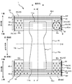
- FIG. 2 is a plan view of the expanded diaper 1 as viewed from the skin side.
- FIG. 3 is a diagram illustrating the AA cross section of FIG.
- FIG. 4A is a diagram showing a part of the belt-like ventral exterior member 300 in an elongated state before the slit S (through hole 50) is formed.
- FIG. 4B is a view showing a part of the belt-like ventral exterior member 300 in an elongated state when the slit S (through hole 50) is formed.
- FIG. 4C is a diagram illustrating a part of the ventral-side exterior member 30 in the wearing state.
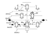
- FIG. 5 is an enlarged view of a portion B in FIG.
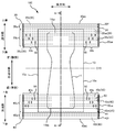
- Drawing 6 is a top view which looked at diaper 100 of other embodiments from the skin side.
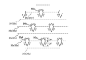
- FIG. 7 is a diagram illustrating a through hole 50 according to another embodiment.
- An absorbent article provided with at least one of the elastic members along the lateral direction, wherein a first through hole and a second through hole penetrating from the skin side to the non-skin side are provided,
- the first through hole overlaps with the elastic member in the longitudinal direction
- the second through hole is adjacent to the first through hole in the longitudinal direction
- the elastic member is
- the absorbent article is discontinuous in the first through hole, and has another elastic member between the first through hole and the second through hole in the longitudinal direction.
- the through-holes of the elastic member are secured while ensuring the fit of the absorbent article by the expansion and contraction of the other elastic member provided between the first through-hole and the second through-hole. Since it becomes easy to make a hole according to shrinkage
- the elastic member when the elastic member is the first elastic member, a second elastic member different from the first elastic member is provided, and in the lateral direction, the second elastic member is the second penetration member. It is desirable to be discontinuous within the pores.
- the through hole can be easily opened according to the contraction of the elastic member, so that the air permeability of the absorbent article can be further improved.
- the absorbent main body is provided, and the first through hole and the second through hole are provided below the upper end of the absorbent main body in the longitudinal direction.
- the first through hole and the second through hole are provided in the vicinity of the shading portion that is more likely to sweat, and the air permeability of the absorbent article can be further improved.
- a plurality of elastic members including the first elastic member, the second elastic member, and the other elastic member are provided, and the absorbent main body has an absorbent body that absorbs excrement.
- the number of elastic members that are discontinuous in the lateral direction by the through-hole penetrating from the skin side to the non-skin side includes an upper region above the upper end of the absorber, It is desirable that the lower region is lower than the upper end.
- the number of elastic members that are discontinuous in the lateral direction is larger in the lower region than in the upper region due to through holes that penetrate from the skin side to the non-skin side. .
- a plurality of elastic members including the first elastic member, the second elastic member, and the other elastic member are provided on the ventral side portion and the back side portion, respectively. It is desirable that the number of elastic members discontinuous in the lateral direction is different between the ventral side portion and the back side portion due to the through-hole penetrating from the skin side to the non-skin side.
- At least one of the abdominal side portion and the back side portion has a third through hole overlapping with the first elastic member in the longitudinal direction, and in the lateral direction,
- the first elastic member is discontinuous in the third through hole, and the first through hole and the third through hole are separated from each other by a predetermined distance in the lateral direction.
- the absorbent article can be fitted more appropriately by the first through hole, the third through hole, and the first elastic member.
- the absorbent article has a fourth through hole that overlaps the second elastic member in the longitudinal direction, and the second elastic member is not in the fourth through hole in the lateral direction.
- the second through hole and the fourth through hole are separated by a predetermined distance, and the third through hole is provided in a number different from the fourth through hole. It is desirable.
- the absorbent article can be fitted more appropriately depending on the number of the third and fourth through holes.
- a distance between the first elastic member and the other elastic member in the longitudinal direction is shorter than a length of the first through hole.
- a larger through-hole can be formed, and the air permeability of the absorbent article can be improved.
- the elastic member adjacent to the first elastic member from the side opposite to the side where the other elastic member is provided is the first penetration in the lateral direction. It is desirable that the portion overlapping the hole is continuous.
- the circumference of the first through hole can be protruded to the skin side or the non-skin side by the expansion and contraction of the elastic member provided above and below the first through hole, and soft to the wearer. Can give touch.
- a plurality of elastic members including the first elastic member, the second elastic member, and the other elastic member are provided on the ventral side portion and the back side portion, respectively. It is desirable that the other elastic member on the ventral side portion and the other elastic member on the back side portion are provided at different positions in the longitudinal direction.
- the center position of the first elastic member is different from the center position of the first through hole in the longitudinal direction.
- the shape of the through hole can be made asymmetrical in the vertical direction, and the impression of the through hole given to the wearer can be changed.
- a plurality of elastic members including the first elastic member, the second elastic member, and the other elastic member are provided, and penetrates from the skin side to the non-skin side in the longitudinal direction.
- the through hole does not overlap with the uppermost elastic member located on the uppermost side among the plurality of elastic members, and the first through hole overlaps with the elastic member adjacent to the first elastic member in the longitudinal direction. It is desirable that the first elastic member overlaps the first elastic member.
- the wearer's waistline can be appropriately fitted by the upper elastic member that is not cut by the through hole. Further, in the longitudinal direction, the first through hole and the first elastic member do not overlap with the elastic member adjacent to the first elastic member, so that the through hole is lifted in the vertical direction when worn. The risk of tearing can be reduced.
- a through-hole penetrating from the skin side to the non-skin side in the longitudinal direction does not overlap with the lowermost elastic member positioned on the lowermost side among the plurality of elastic members.
- the lower fit of the absorbent article can be ensured, and the risk of excrement etc. leaking and leaking from around the legs can be reduced.
- FIG. 2 is a plan view of the expanded diaper 1 as viewed from the skin side.
- FIG. 3 is a diagram illustrating the AA cross section of FIG.
- the diaper 1 in the state of FIG. 1 includes a “vertical direction”, a “lateral direction” that intersects the longitudinal direction, and a “thickness direction” that intersects the longitudinal direction and the lateral direction.
- the longitudinal direction of the diaper 1 in the state of FIG. 2 is referred to as “longitudinal direction”, and one end and the other end in the longitudinal direction of the diaper 1 are respectively referred to as “upper end”.
- C10 is also referred to as “lower end”.
- the side in contact with the wearer is referred to as “skin side” and the opposite side is referred to as “non-skin side”.
- the “extended state” refers to a state in which the diaper 1 is extended until wrinkles disappear. Specifically, the members (for example, the abdominal side exterior member 30 and the back side exterior member 40) of the diaper 1 are used. It means a state in which the dimensions are extended until the dimension is equal to or close to the dimension of the single member.
- a disposable diaper 1 according to the present embodiment (hereinafter referred to as “diaper 1”) is a so-called three-piece type pants-type diaper mainly intended for wearing infants, and has an absorptivity disposed between the wearer's crotch. It has a main body 10, an abdominal exterior member (abdominal side part) 30 that covers the wearer's abdominal side part, and a back side exterior member (back side part) 40.
- the absorbent main body 10 extends from the abdominal exterior member 30 to the back exterior member 40 such that each end in the longitudinal direction overlaps the abdominal exterior member 30 and the back exterior member 40. And are bonded and fixed to the ventral exterior member 30 and the back exterior member 40 from the skin side by an adhesive or the like.
- the external shape is substantially H-shaped in plan view. Then, it is folded in half with the substantially central portion C10 in the longitudinal direction as a folding position, and the abdominal exterior member side edge 30se, which is the lateral ends of the abdominal exterior member 30 and the back exterior member 40 facing each other, When joined and connected at the backside exterior member edge 40se, the diaper 1 (FIG. 1) is formed with the waistline opening 1HB and the pair of leghole openings 1HL.
- the absorptive main body 10 is not overlapped in the region of the upper end portion 30e in the vertical direction of the abdominal exterior member 30, and the absorbent main body 10 is located in the central portion 30c in the vertical direction with respect to the end portion 30e.
- the absorptive main body 10 is piled up in the center part of the horizontal direction among the abdominal side exterior members 30, and the absorptive main body 10 is located in the area
- FIG. Are not superimposed.
- the absorbent main body 10 is not overlapped in the region of the upper end portion 40e in the vertical direction, and is absorbed by the portion 40c on the central side in the vertical direction from the end portion 40e.
- the sex body is superimposed.
- the absorptive main body 19 is piled up in the center part of the horizontal direction among the back side exterior members 40, and the absorptive main body 10 is located in the area
- the absorptive main body 10 is equipped with the absorber 11, the surface sheet member 13 which covers the absorber 11 from the skin side, and the back surface sheet member 15 which covers the absorber 11 from the non-skin side.
- the top sheet member 13 is a liquid-permeable sheet member such as a nonwoven fabric.
- the back sheet member 15 is a sheet member composed of two layers of a liquid-impermeable leak-proof sheet 15a such as polyethylene and a liquid-permeable exterior sheet 15b such as a nonwoven fabric. Further, a three-dimensional gather or a leg-around gather may be formed by the exterior sheet 15b or the like (not shown).
- the absorbent body 11 is an absorbent core formed by laminating liquid absorbent materials, and can absorb excrement such as urine.
- the absorbent body 11 can use liquid absorbent fibers such as pulp fibers, absorbent polymer (SAP), or the like, and has a substantially hourglass shape in plan view in this embodiment (FIG. 2).
- the absorber 11 may be coat
- the ventral side exterior member 30 and the back side exterior member 40 are both substantially rectangular sheet members in plan view made of a flexible material such as a nonwoven fabric.
- the abdominal exterior member 30 has a skin side sheet 31 and a non-skin side sheet 32 stacked in order from the skin side in the thickness direction, and the back side exterior member 40 is joined in the thickness direction.
- the skin side sheet 41 and the non-skin side sheet 42 are overlapped and joined in order from the skin side.
- the upper part of the abdominal exterior member 30 is configured so that the non-skin side sheet 32 starts from the abdominal upper end 30et which is the upper end of the abdominal exterior member 30 in order to improve touch and durability.
- the folded portion 32f is formed by folding downward on the skin side.
- the upper part of the backside exterior member 40 is also folded back downward on the skin side from the backside upper end 40et, which is the upper end of the backside exterior member 40, to form a folded portion 42f. Has been.
- the abdominal exterior member 30 includes a sheet member 34 disposed so as to cover the lower end portion of the folded portion 32f and the upper end portion of the absorptive main body 10 from the skin side.
- the back-side exterior member 40 includes a sheet 44 that is disposed so as to cover the upper end portion on the back side of the absorbent main body 10 from the skin side from the lower side of the folded portion 42f.
- the sheet members 34 and 44 are rectangular sheet members made of a nonwoven fabric or the like, which are different from the ventral exterior member 30 and the back exterior member 40.
- ventral side exterior member 30 and the back side exterior member 40 have a predetermined length in the vertical direction, and a through-hole 50 that penetrates each exterior member 30, 40 from the skin side to the non-skin side is provided vertically.
- a plurality are provided at predetermined intervals in the direction and the horizontal direction. Details of the through hole 50 will be described later.
- a plurality of elastic members 35, 35 are arranged side by side with a space in the vertical direction.
- a plurality of elastic members 45, 45... is bonded and fixed to the skin-side sheet 41 and the non-skin-side sheet 42 with an adhesive while being stretched in the lateral direction.
- the plurality of elastic members 45, 45... Are arranged side by side with a space in the vertical direction.
- the elastic members 35 and 45 provide lateral stretchability to the abdominal exterior member 30 and the back exterior member 40, and form a plurality of ridges on the abdominal exterior member 30 and the back exterior member 40. .
- the region overlapping with the absorber 11 near the central portion in the lateral direction is discontinuous so that the stretching force does not act. Thereby, the shrinkage
- Side elastic members 35 s and 45 s are provided in the laterally outer region from the absorber 11.
- the plurality of elastic members 35 are provided on the upper side of the upper elastic member 35t located on the uppermost side and the upper elastic member 35t, and from the side edge portion 30se on the other side to the ventral side exterior member side edge 30se in the lateral direction.
- a lowermost elastic member 35u provided at a position farthest below the member 35s.
- the plurality of elastic members 45 are provided on the uppermost upper elastic member 45t and on the lower side of the upper elastic member 45t, and from the back side exterior member side edge 40se on the one side in the lateral direction to the other side.
- a lowermost elastic member 45u provided at a position farthest from the lower elastic member 45s.
- the through hole 50 of the ventral-side exterior member 30 is formed in the manufacturing process of the ventral-side exterior member 30 in the manufacture of the diaper 1.
- the ventral-side exterior member 30 is a band-shaped ventral-side exterior member 300 in which a strip-shaped skin-side sheet 310, an elastic member 350, and a strip-shaped non-skin-side sheet (not shown) are arranged in order from the skin side. It is formed separately.
- FIG. 4A is a view showing a part of the belt-shaped ventral-side exterior member 300 in an elongated state before the slit S (through hole 50) is formed.
- FIG. 4B is a view showing a part of the belt-like ventral exterior member 300 in an elongated state when the slit S (through hole 50) is formed.
- FIG. 4C is a diagram illustrating a part of the ventral-side exterior member 30 in the wearing state. 4A, 4B, and 4C are views seen from the skin side, respectively.
- FIG. 4A shows a state in which the band-shaped ventral-side exterior member 300 before the slit S is formed is stretched until the band-shaped skin-side sheet 310 and the band-shaped non-skin-side sheet are almost free from wrinkles.
- linear slits S are formed along the vertical direction so as to cross a part of the elastic members 350 in the elongated strip-shaped ventral exterior member 300.
- the slit S is formed by cutting the strip-shaped skin side sheet 310, the elastic member 350, and the strip-shaped non-skin side sheet using a predetermined blade.
- FIG. 4B shows the moment when the slit S is formed by cutting.
- the slit S then becomes a through hole as shown in FIG. 4C by the elastic member 350.
- the slit S of this embodiment is a linear slit, and unlike the case where the shape which has a predetermined area is cut out, it is hard to produce chips.
- FIG. 4C shows a part of the ventral-side exterior member 30 in a state where the wearer wears the diaper 1.
- the outline of the through-hole 50 of the abdomen-side exterior member 30 in the worn state is opened on both sides in the lateral direction, and the shape of the through-hole 50 is substantially rhombus. This is because, as shown in FIG. 4C, the elastic member 35 contracts, so that the periphery of the through hole 50 is pulled in the lateral direction.
- the through-hole 50 opens more largely in a wearing condition, the air permeability of the diaper 1 can be improved more. By making one through hole 50 larger, the air permeability of the diaper 1 can be ensured with a smaller number of through holes 50.
- the through-hole 50 can be opened in the lateral direction by the elastic member 35 in a contracted state even before being worn, it is possible to provide an appearance to a guardian who wears the diaper 1 on a wearer such as an infant.
- the through-hole 50 can be visually recognized, and the improvement of the air permeability can be recognized.
- the contracted elastic member 35 pulls the nonwoven fabric around the through hole 50, so that a plurality of wrinkles along the outline of the through hole 50 are formed around the through hole 50. By the plurality of folds, the touch of the diaper 1 can be made softer.
- the through hole is formed by cutting out a predetermined range, the periphery of the through hole is opened in a substantially flat state, whereas in the present embodiment, the through hole 50 is formed by a linear slit S. Therefore, the non-woven fabric pulled by the opening swells around the through hole 50 to form a plurality of wrinkles. Therefore, the touch of the diaper 1 can be further improved.
- the through hole 50 of the backside exterior member 40 is formed in the same manner as the through hole 50 of the abdominal side exterior member 30.
- the case where the through holes 50 of the ventral exterior member 30 and the back exterior member 40 are separately formed has been described.
- the present invention is not limited to this.
- dorsal exterior member 40 integrally and forming the through-hole 50 you may isolate
- the slit S may be formed after the absorbent main body 10 and the sheet member 34 are stacked on the ventral-side exterior member 30, or after the slit S is formed in the ventral-side exterior member 30.
- the sheet member 34 may be stacked.
- the slit S may be formed after the absorbent main body 10 and the sheet member 44 are stacked on the backside exterior member 40, or the absorbent main body 10 and the sheet are formed after the slit S is formed on the backside exterior member 40.
- the member 44 may be overlapped.
- a plurality of through holes 50 of the ventral-side exterior member 30 are provided in a region of the ventral-side exterior member 30 where the folded portion 32f, the sheet member 34, and the absorbent main body 10 are not provided.
- the vertical direction is a region below the end 30 e and below the lower end of the sheet member 34, and the horizontal direction is provided outside the absorbent main body 10.
- the one side and the other side in the lateral direction of the ventral-side exterior member 30 are arranged symmetrically with respect to the lateral center AA.
- the through-hole 50 is below the upper elastic member 35t positioned on the uppermost side of the ventral-side exterior member 30 and above the lowermost elasticity 35u positioned on the lowermost side of the ventral-side elastic member 30 in the vertical direction. Is provided.
- the continuous elastic member 35m and the side elastic member 35s are partially discontinuous. This is because the continuous elastic member 350 is cut together with the continuous skin side sheet and the continuous skin side sheet 320 when the through hole 50 is formed as described above.
- the upper elastic member 35t and the lowermost elastic member 35u are not discontinuous by the through hole 50.
- the number of the elastic members 35 made non-continuous by the through hole 50 is different between a region above the upper end 11ta of the absorber 11 and a region below the upper end 11ta of the absorber 11. That is, due to the formation of the through hole 50, the elastic member 35 in the region below the upper end 11ta is discontinuous.
- One elastic member 35 is discontinuous on one side in the horizontal direction, for example, the left side in FIG. 2 and the region above the upper end 11ta, whereas the three elastic members 35 penetrate below the upper end 11ta.
- the holes 50 are discontinuous.
- FIG. 5 is an enlarged view of a portion B in FIG.
- a through hole (first through hole) 50 a a through hole (second through hole) 50 b that is positioned diagonally to the left of the through hole 50 a and is adjacent in the vertical direction, and an upper side of the through hole 50 a
- a through hole 50c that is positioned and overlaps the through hole 50a in the lateral direction
- a through hole 50d third through hole
- a through hole 50e (third through hole) located on the right side of the through hole 50a and overlapping with the through holes 50a and 50d in the vertical direction is located diagonally right above the through hole 50a and adjacent in the vertical direction.
- a through hole (fourth through hole) 50f is shown.
- the elastic member (first elastic member) 35a overlaps the through hole 50a, the through hole 50d, and the through hole 50e in the vertical direction.
- the elastic member (second elastic member) 35b includes the through hole 50b and the through hole. 50f overlaps in the vertical direction, and the elastic member 35c overlaps the through hole 50c in the vertical direction.
- the elastic member 35d is provided below the through hole 50a, and the elastic member (other elastic member) 35e is provided between the through hole 50a and the through hole 50b.
- f is provided between the through hole 50b and the through hole c.
- the elastic members 35d, e, and f do not overlap with any through hole 50 in the vertical direction.
- the elastic member 35c is a continuous elastic member 35m
- the elastic members 35a, 35b, 35e, and 35f are side elastic members 35s
- the elastic member 35d is a lowermost elastic member 35u.
- each through-hole 50 has a substantially rhombus shape, and the inside of the through-hole 50 penetrates to the non-skin side.
- the substantially rhombic lateral vertex and the cut end of the elastic member 35 are at substantially the same position.
- disconnected elastic member 35 is not provided inside each through-hole 50, and the cut
- the elastic member 35a is continuous from the lateral outer side to the lateral outer side of the through hole 50d from the through hole 50a, and is not provided inside the through hole 50a and the through hole 50d.
- the elastic member 35b is not provided in the through hole 50b, and the elastic member 35c is not provided in the through hole 50c.
- an adhesive or the like is not provided in a rectangular region (lower left hatched portion in FIG. 5) surrounded by a side g along the lateral direction circumscribing each through hole 50 and a side h along the vertical direction.
- the skin side sheet 31 and the non-skin side sheet 32 are joined by an adhesive applied to the elastic member 35.
- each through hole 50 has substantially the same size, and in the vertical direction, the through hole 50a and the through hole 50c overlap in the horizontal direction.
- L1 is larger than L2 (L1> L2).
- the length L3 in the longitudinal direction of the elastic member discontinuous by the through hole 50 and the elastic member adjacent to the discontinuous elastic member in the vertical direction and not discontinuous by the through hole 50 is: It is shorter than the length L2 of the through hole 50 (L3 ⁇ L2).
- the distance L3 between the elastic member 35a and the elastic member 35e is smaller than the vertical length L2 of the through hole 50a.
- the number of through holes 50 that overlap the elastic member 35 in the lateral direction can be arbitrarily changed.
- the holes 50 are two through holes 50b and 50f.
- the configuration of the through hole 50 of the ventral side exterior member 30 has been described, the configuration of the through hole 50 in the back side exterior member 40 is substantially the same as that of the ventral side exterior member 30.
- the plurality of through holes 50 of the backside exterior member 40 are also arranged symmetrically with respect to the lateral center AA on the one side and the other side in the lateral direction, like the ventral side exterior member 30.
- the through-hole 50 of the diaper 1 of this embodiment can adjust the tension
- the elastic member 35a and the elastic member 35e are elastic members made of the same material, and before the slit S (the through hole 50a and the through hole 50d) is formed, the skin side sheet 31 and the non-skin side sheet 32 are similarly stretched. Bonded and fixed.
- the elastic member 35a is cut by the slit S (the through hole 50a and the through hole 50d), and the elastic member 35e is not cut by any of the slits S.
- the elastic member 35e adjacent to the elastic member 35a in the vertical direction is provided with a tensile strength in the horizontal direction from Te to the position overlapping the absorber 11 from the left side (center side) of the through hole 50d in the thickness direction.
- the tension in the lateral direction of the elastic member 35a is Ta1
- the tension Ta1 is smaller than the tension Te (Ta1 ⁇ Te).
- the magnitude of the lateral tension of the elastic member 35a located between the through hole 50d and the through hole 50a is Ta2
- the tension Ta2 is smaller than the tension Te (Ta2 ⁇ Te)
- the tension is smaller than Ta1 (Ta2 ⁇ Ta1).
- the elastic member 35a is discontinuous by the through holes 50a, 50d, etc., when the force in the vertical direction and the horizontal direction is applied, the elastic member 35a is compared with the case where it is continuous. It can expand and contract more freely.
- the elastic member 35a on the left side of the through hole 50d and the elastic member 35a positioned between the through hole 50a and the through hole 50d can expand and contract more freely with respect to movement than when they are continuous. Therefore, it becomes easy to follow not only the movement in the horizontal direction but also the movement in the vertical direction. Thereby, the fitting property of the abdomen or the buttocks of the diaper 1 can be improved.
- the tension of the elastic member 35 can be adjusted by providing the elastic member 35 cut by the slit S (through hole 50) and the elastic member 35 not cut by the slit S (through hole 50). Therefore, it is possible to reduce the risk of excessive tightening while securing tightening around the waist, and to improve the fit of the diaper 1.
- the through hole 50a overlaps the elastic member 35a in the vertical direction, and the through hole 50b is adjacent to the through hole 50a in the vertical direction.
- the elastic member 35a is discontinuous in the through hole 50a in the lateral direction, and has an elastic member 35e between the through hole 50a and the through hole 50b in the vertical direction.
- the through hole 50b can be further opened according to the contraction of the elastic member 35b, like the through hole 50a, and the diaper The air permeability of 1 can be further improved.
- the through holes 50 similarly to the through holes 50a and 50b, the through holes 50 such as the through holes 50c, 50d, 50e, and 50f are similarly provided with the elastic member 35 in the through holes 50 in the lateral direction. It is continuous and opens more widely, improving air permeability.
- the through hole 50a and the through hole 50b are provided in the portion 30c below the upper end of the absorbent main body 10 in the vertical direction.
- the upper side of the abdominal side of the absorbent main body 10 is located above the upper end of the back side, and the upper side of the abdominal side of the absorbent main body 10.
- Through holes 50a and 50b are provided on the lower side.
- the number of elastic members 35 that are discontinuous in the lateral direction by the plurality of through holes 50 includes the upper region above the upper end 11ta of the absorber 11 and the upper end 11ta of the absorber 11. It is different from the lower area below. Further, the number of the elastic members 35 discontinuous by the plurality of through holes 50 is larger in the lower region below the upper end 11ta of the absorber 11 than in the upper region above the upper end 11ta of the absorber 11. It is more preferable. As shown in FIG. 2, in the ventral exterior member 30 of the diaper 1, the number of elastic members 35 that are discontinuous in the lateral direction is lower in the lower region than the upper end 11 ta of the absorbent body 11. Many.
- the expansion and contraction of the elastic member 35 according to the wearer's movement can be adjusted.
- the lower side of the diaper 1 is moved more than the upper side by moving the leg, so the lower side of the diaper 1 is more free of the elastic member 35 than the upper side. Expansion and contraction is required. Therefore, by providing more elastic members 35 discontinuous by the plurality of through holes 50 in the lower region below the upper end 11ta of the absorber 11, it becomes easier to follow the movement of the wearer, and the diaper 1 The fitting property can be improved.
- the number of the elastic members 35 that are not necessarily continuous by the plurality of through holes 50 is the upper region above the upper end 11t of the absorber 11 and the lower region below the upper end 11t of the absorber 11. There is no need to be different. Like the backside exterior member 40 shown in FIG. 2, the upper region above the upper end 11 tb of the absorber 11 and the lower region below the upper end 11 tb of the absorber 11 are discontinuous by the through holes 50.
- the number of elastic members may be the same.
- a plurality of through holes 50 may be provided in a region above the upper end 11t of the absorber 11.
- FIG. 6 elasticity that is discontinuous by the plurality of through holes 50 in the upper region above the upper end 11 t of the absorber 11 and the lower region below the upper end 11 t of the absorber 11.
- the number of members 35 may be the same.
- Drawing 6 is a top view which looked at diaper 100 of other embodiments from the skin side.
- the arrangement of the through holes 50 in the abdominal exterior member 30 and the back exterior member 40 may be substantially the same. At this time, the through holes 50 are provided only on the lower side where sweating is more likely to occur, You may arrange
- the number and arrangement of the elastic members 35 that are discontinuous by the plurality of through holes 50 can be appropriately changed in consideration of improvement in air permeability and movement of the wearer.
- the abdominal exterior member 30 and the back exterior member 40 are each provided with a plurality of elastic members 35, and elastic members that are discontinuous in the lateral direction by the through holes 50.
- the number 35 is different between the ventral exterior member 30 and the back exterior member 40.
- the number of the elastic members 35 discontinuous by the through holes 50 is larger in the back side exterior member 40 than in the abdominal side exterior member 30.
- the elastic member 35 that can be expanded and contracted more freely with respect to movement than in the continuous case is different between the ventral side and the dorsal side.
- the vertical direction has a through hole 50d overlapping the elastic member 35a.
- the elastic member 35a is discontinuous in the through hole 50d, and the horizontal direction
- the through hole 50a and the through hole 50d are separated by a predetermined distance. That is, the through-hole 50a and the through-hole 50d are provided at positions aligned in the lateral direction, and both of them make the elastic member 35a discontinuous. Thereby, the tightening force by the elastic member 35a can be adjusted, and the elastic member 35a can be freely expanded and contracted as compared with the case where it is continuous.
- the elastic member 35a on the left side of the through hole 50d is in a state of being continuous longer than the elastic member 35a located between the through hole 50a and the through hole 50d, the elastic member on the left side of the through hole 50d.
- the tension Ta1 of 35a is larger than the tension Ta2 of the elastic member 35a located between the through hole 50a and the through hole 50d (Ta1> Ta2). Therefore, since the elastic member 35a on the left side of the through hole 50d that overlaps the absorbent main body 10 in the vertical direction can tighten the absorbent main body 10 with a stronger tension, the absorbent main body 10 and the wearer's skin are separated from each other. Can reduce the risk of excrement leaking.
- the elastic member 35a located between the through-hole 50a and the through-hole 50d is used.
- the tension Ta2 weaker it is tightened with an appropriate strength.
- the vertical direction has a through hole 50f overlapping the elastic member 35b.
- the elastic member 35b is discontinuous in the through hole 50f, and in the horizontal direction.
- the through hole 50b and the through hole 50f are separated by a predetermined distance, and the through holes 50d and 50e are provided in a number different from the through hole 50f. That is, on one side (FIG. 5) in the lateral direction of the abdominal exterior member 30, the lower elastic member 35a is discontinuous by the three through holes 50a and the through holes 50d and 50e.
- the elastic member 35b located on the upper side is discontinuous by the two through holes 50b and 50f.
- the number of the through holes 50 that make the elastic member 35 discontinuous is different between the upper side and the lower side, so that in the vertical direction, the through hole that makes the elastic member 35 discontinuous between the upper side and the lower side.
- the degree of freedom when adjusting the tightening force can be made higher than when the number of 50 is the same.
- the distance L3 between the elastic member 35a and the elastic member 35e in the vertical direction is shorter than the length L2 of the through hole 50a (L3 ⁇ L2).
- the length L2 of the through hole 50a is preferably smaller than the distance (L3 ⁇ 2) between the elastic member 35e and the elastic member 35d in the vertical direction. If the length L2 of the through hole 50a is longer than the distance between the elastic member 35a and the elastic member 35e, the elastic member 35e and the elastic member 35d that are adjacent to the elastic member 35a from above and below may be cut. Because.
- the elastic member 35d adjacent to the elastic member 35a from the side opposite to the side where the elastic member 35e is provided has a continuous portion that overlaps the through hole 50a in the lateral direction. is doing. That is, in FIG. 5, the elastic members 35e and 35d are continuous in a portion X that is a portion overlapping the through hole 50a in the lateral direction. As a result, a larger number of ridges formed obliquely along the outline of the through hole 50a around the through hole 50a can be maintained.
- the through hole 50 is provided above the through hole 50a without having the elastic member 35e continuous above the through hole 50a, the flange formed by the through hole 50 provided on the upper side, and the through hole
- the wrinkles formed by 50a may interfere with each other, and the wrinkles in the respective oblique directions may be suppressed. Therefore, by providing the elastic members 35e and 35d on the upper side and the lower side, respectively, in the portion X, the reduction of wrinkles due to wrinkle interference caused by the plurality of through holes 50 is suppressed, and more oblique wrinkles are maintained and softer. Can give touch.
- the belly side exterior member 30 and the back side exterior member 40 are respectively provided with an elastic member 35a, an elastic member 45a (first elastic member, not shown), an elastic member 35b, and an elastic member 45b (second elastic member, not shown).
- a plurality of elastic members 35 and 45 including an elastic member 35e and an elastic member 45e (other elastic members, not shown) that are not discontinuous by the through-hole 50 are provided.
- the elastic member 35e and the elastic member 45e of the backside exterior member 40 are provided at different positions in the vertical direction. Thereby, the possibility that the continuous elastic member 35e and the elastic member 45e excessively tighten the wearer's skin at the same position in the lateral direction can be reduced.
- FIG. 7 is a diagram illustrating a through hole 50 according to another embodiment.
- the distance Lu from the upper vertex of the through hole 50a to the center position of the elastic member 35a is smaller than the distance Ld from the lower vertex of the through hole 50a to the center position of the elastic member 35a. That is, the center position in the vertical direction of the through hole 50a is located below the center position of the elastic member 35a, and the through hole 50a has an asymmetric shape in the vertical direction. This is formed by cutting the lower side of the elastic member 35 longer when the slit S is formed.
- FIG. 7 shows a part of the abdominal exterior member 30 in an extended state, and when the extension before the diaper 1 is worn from this state is loosened, a plurality of parts formed below the through hole 50a.
- the top of the heel (the end of the heel in the thickness direction) falls toward the inner side in the lateral direction of the through hole 50a.
- the lower side of the through hole 50a can be made smaller in appearance.
- the center position of the through hole 50 in the vertical direction and the center position of the elastic member 35a can be changed as appropriate, and the center position of the through hole 50a in the vertical direction is not necessarily provided below the center position of the elastic member 35a. It does not have to be.
- the center position of the through hole 50a in the vertical direction may be provided above the center position of the elastic member 35a.
- the some elastic member 35 containing the elastic member 35a, the elastic member 35b, and the elastic member 35e is provided, and the through-hole 50 is the most among the some elastic members 35 in the vertical direction. It does not overlap with the upper elastic member 35t located on the upper side. Accordingly, the uppermost elastic member 35t is not cut, and a continuous elastic member can be maintained in the waistline opening 1HB. Therefore, even when the through hole 50 is formed to improve the air permeability, At the time of wearing, the tightening force by the elastic member 35t around the wearer's waist can be secured, so that the possibility of excrement etc. leaking due to insufficient tightening of the waist opening 1HB can be reduced.
- the through hole 50a does not overlap with the elastic member 35e adjacent to the elastic member 35a, but overlaps with the elastic member 35a.
- the diaper 1 Even when a vertical force is applied to the elastic member 35d, the elastic members 35d and 35e that are not discontinuous by the through hole 50 are provided, and therefore the elastic member 35d is surrounded by the force applied from the outside around the through hole 50a. It is possible to reduce the risk of tearing to the lower side or the upper side of the elastic member 35e. Furthermore, the tightening of the wearer's abdomen and buttocks can be ensured, and the fear that the diaper 1 will fall or the wearing position will shift can be reduced.
- the through hole 50 does not overlap with the lowermost elastic member 35u located on the lowermost side among the plurality of elastic members 35. Accordingly, since the lowermost elastic member 35u is not discontinuous by the through hole 50, the fit of the leg periphery opening 1HL can be secured, and the risk of excrement etc. leaking from the leg periphery opening 1HL is reduced. be able to.
- the through holes 50 are formed in the ventral exterior member 30 and the back exterior member 40, respectively, but the present invention is not limited thereto. What formed the through-hole 50 in either the stomach side exterior member 30 or the back side exterior member 40 may be used. However, the air permeability of the diaper 1 can be further improved by forming the through holes 50 in both the abdominal side exterior member 30 and the back side exterior member 40.
- the sheet members 34 and 44 are provided on the skin side of the abdominal exterior member 30 and the back exterior member 40, respectively, but the present invention is not limited thereto.
- the sheet members 34 and 44 may be provided on either the stomach-side exterior member 30 or the back-side exterior member 40, or both may not be provided.
- each through hole 50 is configured such that one elastic member 35 is discontinuous in the lateral direction, but is not limited thereto. It is not always necessary for all the through holes 50 to be discontinuous with the elastic member 35, and it may include a configuration in which the elastic member 35 is continuous in the through hole 50, or in a region where the elastic member 35 is not provided.
- the formed through hole 50 may be included.
- one elastic member 35e that is not discontinuous by the through hole 50 is provided between the through hole 50a and the through hole 50b in the vertical direction.
- Two or more elastic members 50e that are not discontinuous by the through holes 50 may be provided.
- one elastic member 35 that is not discontinuous by the through hole 50 is provided between the through hole 50 provided on the upper side and the through hole 50 provided on the lower side in the vertical direction.
- the elastic member 35 that is not discontinuous by the through hole 50 may not be provided between the upper through hole 50 and the lower through hole 50.
- the through-hole 50 is formed by forming a linear slit along the vertical direction, but the present invention is not limited to this.
- a through-hole may be formed by cutting out a range of a certain area, or a curved slit or the like may be formed.
- the diaper 1 according to the above-described embodiment is intended for wearing infants, the present invention is not limited to this, and adults may be intended for wearing.
- a 3 piece type disposable diaper 1 was illustrated as an example of an absorbent article, it is not restricted to this at all.
- a two-piece disposable diaper or tape having an exterior sheet having an abdominal part, a crotch part, and a dorsal part as a first part and an absorbent main body fixed to the skin side of the exterior sheet as a second part
- a disposable disposable diaper may be used.
Landscapes
- Health & Medical Sciences (AREA)
- Epidemiology (AREA)
- Engineering & Computer Science (AREA)
- Biomedical Technology (AREA)
- Heart & Thoracic Surgery (AREA)
- Vascular Medicine (AREA)
- Life Sciences & Earth Sciences (AREA)
- Animal Behavior & Ethology (AREA)
- General Health & Medical Sciences (AREA)
- Public Health (AREA)
- Veterinary Medicine (AREA)
- Dermatology (AREA)
- Absorbent Articles And Supports Therefor (AREA)
Abstract
互いに直交する縦方向と横方向とを有し、着用者の腹側に設けられる腹側部(30)と、前記着用者の背側に設けられる背側部(40)と、前記腹側部(30)及び前記背側部(40)の少なくともいずれか一方に設けられ、前記横方向に沿った弾性部材(35)とを備える吸収性物品(1)であって、肌側から非肌側に貫通する第1貫通孔(50a)及び第2貫通孔(50b)が設けられており、前記第1貫通孔(50a)は、前記縦方向において前記弾性部材(35a)と重なっており、前記第2貫通孔(50b)は、前記縦方向において前記第1貫通孔(50a)と隣接しており、前記横方向において、前記弾性部材(35a)は、前記第1貫通孔(50a)内で非連続であり、前記縦方向において、前記第1貫通孔(50a)と前記第2貫通孔(50b)との間に、他の弾性部材(35e)を有する。
Description
本発明は、吸収性物品に関する。
従来、尿などの排泄物を吸収する吸収性物品として使い捨ておむつ等が知られている。例えば、文献1に示すように、パンツ型使い捨ておむつ1は外装体3と吸収性本体2を有しており、外装体3には、厚さ方向に貫通する複数の孔5が設けられている。この複数の孔5を設けることで、吸収性物品の通気性を向上させることができる。
しかしながら、文献1に示す使い捨ておむつ1においては、複数の孔5は、縦方向に列をなすように配されているため、着用者が着用しようとする際等にパンツ型使い捨ておむつ1に上下方向への力を加えると、孔5の周囲が裂けてしまう恐れがあり、着用時において、パンツ型使い捨ておむつ1が適切に着用者の胴回りにフィットしない場合や、その周囲が裂けてしまった孔5から排泄物が漏れてしまうのではないかと着用者に感じさせる恐れがあった。
本発明は、上記のような従来の問題に鑑みてなされたものであって、その目的は、使い捨て吸収性物品の通気性を向上させつつ、吸収性物品のフィット性を向上させることにある。
上記目的を達成するための主たる発明は、
互いに直交する縦方向と横方向とを有し、着用者の腹側に設けられる腹側部と、前記着用者の背側に設けられる背側部と、前記腹側部及び前記背側部の少なくともいずれか一方に設けられ、前記横方向に沿った弾性部材とを備える吸収性物品であって、肌側から非肌側に貫通する第1貫通孔及び第2貫通孔が設けられており、前記第1貫通孔は、前記縦方向において前記弾性部材と重なっており、前記第2貫通孔は、前記縦方向において前記第1貫通孔と隣接しており、前記横方向において、前記弾性部材は、前記第1貫通孔内で非連続であり、前記縦方向において、前記第1貫通孔と前記第2貫通孔との間に、他の弾性部材を有することを特徴とする吸収性物品である。
本発明の他の特徴については、本明細書及び添付図面の記載により明らかにする。
互いに直交する縦方向と横方向とを有し、着用者の腹側に設けられる腹側部と、前記着用者の背側に設けられる背側部と、前記腹側部及び前記背側部の少なくともいずれか一方に設けられ、前記横方向に沿った弾性部材とを備える吸収性物品であって、肌側から非肌側に貫通する第1貫通孔及び第2貫通孔が設けられており、前記第1貫通孔は、前記縦方向において前記弾性部材と重なっており、前記第2貫通孔は、前記縦方向において前記第1貫通孔と隣接しており、前記横方向において、前記弾性部材は、前記第1貫通孔内で非連続であり、前記縦方向において、前記第1貫通孔と前記第2貫通孔との間に、他の弾性部材を有することを特徴とする吸収性物品である。
本発明の他の特徴については、本明細書及び添付図面の記載により明らかにする。
本発明によれば、第1貫通孔と第2貫通孔の間に設けられた他の弾性部材の伸縮によって、吸収性物品のフィット性を確保しつつ、貫通孔を弾性部材の収縮に応じて開孔させやすくなるため、吸収性物品の通気性をより向上させることができる。
本明細書及び添付図面の記載により、少なくとも以下の事項が明らかとなる。
互いに直交する縦方向と横方向とを有し、着用者の腹側に設けられる腹側部と、前記着用者の背側に設けられる背側部と、前記腹側部及び前記背側部の少なくともいずれか一方に設けられ、前記横方向に沿った弾性部材とを備える吸収性物品であって、肌側から非肌側に貫通する第1貫通孔及び第2貫通孔が設けられており、前記第1貫通孔は、前記縦方向において前記弾性部材と重なっており、前記第2貫通孔は、前記縦方向において前記第1貫通孔と隣接しており、前記横方向において、前記弾性部材は、前記第1貫通孔内で非連続であり、前記縦方向において、前記第1貫通孔と前記第2貫通孔との間に、他の弾性部材を有することを特徴とする吸収性物品である。
互いに直交する縦方向と横方向とを有し、着用者の腹側に設けられる腹側部と、前記着用者の背側に設けられる背側部と、前記腹側部及び前記背側部の少なくともいずれか一方に設けられ、前記横方向に沿った弾性部材とを備える吸収性物品であって、肌側から非肌側に貫通する第1貫通孔及び第2貫通孔が設けられており、前記第1貫通孔は、前記縦方向において前記弾性部材と重なっており、前記第2貫通孔は、前記縦方向において前記第1貫通孔と隣接しており、前記横方向において、前記弾性部材は、前記第1貫通孔内で非連続であり、前記縦方向において、前記第1貫通孔と前記第2貫通孔との間に、他の弾性部材を有することを特徴とする吸収性物品である。
このような吸収性物品によれば、第1貫通孔と第2貫通孔の間に設けられた他の弾性部材の伸縮によって、吸収性物品のフィット性を確保しつつ、貫通孔を弾性部材の収縮に応じて開孔させやすくなるため、吸収性物品の通気性をより向上させることができる。
かかる吸収性物品において、前記弾性部材を第1弾性部材としたとき、前記第1弾性部材と異なる第2弾性部材が設けられており、前記横方向において、前記第2弾性部材は前記第2貫通孔内で非連続であることが望ましい。
このような吸収性物品によれば、貫通孔を弾性部材の収縮に応じて開孔させやすくなるため、吸収性物品の通気性をより向上させることができる。
かかる吸収性物品において、吸収性本体を備えており、前記縦方向において、前記第1貫通孔及び前記第2貫通孔が、前記吸収性本体の上端より下側に設けられていることが望ましい。
このような吸収性物品によれば、より汗をかきやすいそけい部の近くに第1貫通孔及び第2貫通孔を設けられ、吸収性物品の通気性をより向上させることができる。
かかる吸収性物品において、前記第1弾性部材、前記第2弾性部材、及び前記他の弾性部材を含む複数の弾性部材が設けられており、前記吸収性本体は、排泄物を吸収する吸収体を有しており、肌側から非肌側に貫通する貫通孔によって、前記横方向に非連続とされている弾性部材の数が、前記吸収体の上端より上側の上側領域と、前記吸収体の上端より下側の下側領域とで異なることが望ましい。
このような吸収性物品によれば、異なる非連続の弾性部材の数によって、着用者により適したフィット性にすることができる。
かかる吸収性物品において、肌側から非肌側に貫通する貫通孔によって、前記横方向に非連続とされている弾性部材の数が、前記上側領域より前記下側領域の方が多いことが望ましい。
このような吸収性物品によれば、下側領域の、弾性部材の伸縮範囲が狭いことによる収縮力が過度に強くなってしまう恐れを軽減することができる。
かかる吸収性物品において、前記腹側部及び前記背側部には、それぞれ前記第1弾性部材、前記第2弾性部材、及び前記他の弾性部材を含む複数の弾性部材が設けられており、前記肌側から非肌側に貫通する貫通孔によって、前記横方向に非連続とされている弾性部材の数が、前記腹側部と前記背側部とで異なることが望ましい。
このような吸収性物品によれば、着用者に適切にフィットさせつつ、吸収性物品の通気性を向上させることができる。
かかる吸収性物品において、前記腹側部及び前記背側部の少なくとも一方において、前記縦方向において、前記第1弾性部材と重なっている第3貫通孔を有しており、前記横方向において、前記第1弾性部材は、前記第3貫通孔内で非連続であり、前記横方向において、前記第1貫通孔と前記第3貫通孔は、所定距離だけ離間していることが望ましい。
このような吸収性物品によれば、第1貫通孔と第3貫通孔、及び第1弾性部材によって、吸収性物品をより適切にフィットさせることができる。
かかる吸収性物品において、前記縦方向において、前記第2弾性部材と重なっている第4貫通孔を有しており、前記横方向において、前記第2弾性部材は、前記第4貫通孔内で非連続であり、前記横方向において、前記第2貫通孔と前記第4貫通孔は、所定距離だけ離間しており、前記第3貫通孔は、前記第4貫通孔とは異なる数だけ設けられていることが望ましい。
このような吸収性物品によれば、第3及び第4貫通孔の数によって、より適度に吸収性物品をフィットさせることができる。
かかる吸収性物品において、前記縦方向における、前記第1弾性部材と前記他の弾性部材との距離は、前記第1貫通孔の長さより短いことが望ましい。
このような吸収性物品によれば、より大きな貫通孔を形成することができ、吸収性物品の通気性を向上させることができる。
かかる吸収性物品において、前記第1弾性部材に関して、前記他の弾性部材が設けられている側とは反対側から前記第1弾性部材に隣接する弾性部材は、前記横方向において、前記第1貫通孔と重なる部分が連続していることが望ましい。
このような吸収性物品によれば、第1貫通孔の上下に設けられた弾性部材の伸縮によって、第1貫通孔の周囲を肌側又は非肌側に突出させることができ、着用者に柔らかい肌触りを与えることができる。
かかる吸収性物品において、前記腹側部及び前記背側部には、それぞれ前記第1弾性部材、前記第2弾性部材、及び前記他の弾性部材を含む複数の弾性部材が設けられており、前記腹側部の前記他の弾性部材と、前記背側部の前記他の弾性部材とが、前記縦方向において異なる位置に設けられていることが望ましい。
このような吸収性物品によれば、弾性部材の伸縮によって、腹側部と背側部の横方向における同じ位置で過度に締め付けてしまう恐れを軽減することができる。
かかる吸収性物品において、前記縦方向において、前記第1弾性部材の中心位置は、前記第1貫通孔の中心位置と異なっていることが望ましい。
このような吸収性物品によれば、貫通孔の形状を上下非対称な形状にすることができ、着用者に与える貫通孔の印象を変えることができる。
かかる吸収性物品において、前記第1弾性部材、前記第2弾性部材、及び前記他の弾性部材を含む複数の弾性部材が設けられており、前記縦方向において、肌側から非肌側に貫通する貫通孔が、前記複数の弾性部材のうち最も上側に位置する上側弾性部材と重なっておらず、前記縦方向において、前記第1貫通孔が、前記第1弾性部材に隣接する弾性部材と重なることなく、前記第1弾性部材と重なっていることが望ましい。
このような吸収性物品によれば、貫通孔によって切断されていない上側弾性部材によって着用者の胴回りを適切にフィットさせることができる。また、縦方向において、第1弾性部材に隣接する弾性部材と重なることなく、第1貫通孔と第1弾性部材が重なる位置に設けることで、着用する際の上下方向への引き上げによって貫通孔が裂けてしまう恐れを軽減することができる。
かかる吸収性物品において、前記縦方向において、肌側から非肌側に貫通する貫通孔が、前記複数の弾性部材のうち最も下側に位置する最下側弾性部材と重なっていないことが望ましい。
このような吸収性物品によれば、吸収性物品の下側のフィット性を確保することができ、排泄物等が漏れて脚周りから漏れてしまう恐れを軽減することができる。
===本実施形態に係る使い捨ておむつについて===
<<<使い捨ておむつ1の構成について>>>
図1は、本実施形態の吸収性物品の一例としてのおむつ1の概略斜視図である。図2は、展開した伸長状態のおむつ1を肌側から見た平面図である。図3は、図2のA-A断面について表す図である。
<<<使い捨ておむつ1の構成について>>>
図1は、本実施形態の吸収性物品の一例としてのおむつ1の概略斜視図である。図2は、展開した伸長状態のおむつ1を肌側から見た平面図である。図3は、図2のA-A断面について表す図である。
以下の説明では、図1の状態(着用状態)のおむつ1は、「縦方向」と、縦方向と交差する「横方向」と、縦方向及び横方向と交差する「厚さ方向」とを有する。また、図2の状態(展開状態)でのおむつ1の長手方向を「長手方向」、おむつ1の長手方向における一端と他端をそれぞれ「上端」といい、長手方向におけるおむつ1の略中央部C10を「下端」ともいう。さらに、厚さ方向のうち、着用者に接触する側を「肌側」、その反対側を「非肌側」という。図2等におけるA-Aは、横方向中心を示している。なお、「伸長状態」とは、おむつ1を皺がなくなるまで伸長させた状態をいい、具体的には、おむつ1を構成する部材(例えば、腹側外装部材30や背側外装部材40)の寸法がその部材単体の寸法と一致又はそれに近い長さになるまで伸長された状態をいう。
本実施形態にかかる使い捨ておむつ1(以下、「おむつ1」と呼ぶ。)は、主に乳幼児を着用対象とした所謂3ピースタイプのパンツ型おむつであり、着用者の股間に配置される吸収性本体10と、着用者の腹側部を覆う腹側外装部材(腹側部)30と、背側外装部材(背側部)40を有している。
図2の展開状態では、吸収性本体10は、長手方向における各端部が、腹側外装部材30と背側外装部材40と重なるように、腹側外装部材30から背側外装部材40に亘って設けられ、接着剤等により腹側外装部材30及び背側外装部材40にそれぞれ肌側から接合固定されている。その外観形状は平面視略H形状をなしている。そして、長手方向の略中央部C10を折り返し位置として二つ折りして、互いに対向する腹側外装部材30と背側外装部材40の横方向の各端部である腹側外装部材側縁部30se、背側外装部材縁部40seにて接合・連結すると、胴回り開口部1HB及び一対の脚回り開口部1HLが形成されたおむつ1(図1)となる。
腹側外装部材30のうち、縦方向の上側の端部30eの領域には、吸収性本体10が重ねられておらず、端部30eよりも縦方向の中央側の部分30cに吸収性本体10が重ねられている。また、腹側外装部材30のうち、横方向の中央部には、吸収性本体10が重ねられており、吸収性本体10の横端10eより横方向外側の領域30sには、吸収性本体10が重ねられていない。
同様に、背側外装部材40のうち、縦方向の上側の端部40eの領域には、吸収性本体10が重ねられておらず、端部40eよりも縦方向の中央側の部分40cに吸収性本体が重ねられている。また、背側外装部材40のうち、横方向の中央部には、吸収性本体19が重ねられており、吸収性本体10の横端10eより横方向外側の領域40sには、吸収性本体10が重ねられていない。
図2及び図3に示すように、吸収性本体10は、吸収体11と、吸収体11を肌側から覆う表面シート部材13と、吸収体11を非肌側から覆う裏面シート部材15を備えている。表面シート部材13は、不織布等の液透過性のシート部材である。裏面シート部材15は、ポリエチレン等の液不透過性の防漏シート15aと不織布等の液透過性の外装シート15bとの2層から構成されるシート部材である。また、外装シート15b等によって立体ギャザーや脚周りギャザーが形成されていてもよい(不図示)。
吸収体11は、液体吸収性素材を積層してなる吸収性コアであり、尿等の排泄物を吸収することができる。吸収体11は、パルプ繊維等の液体吸収性繊維や、吸収性ポリマー(SAP)等を用いることができ、本実施形態においては、平面視略砂時計形状を有している(図2)。また、吸収体11は、ティッシュペーパー等の液透過性シート(不図示)で被覆されていても良い。
腹側外装部材30及び背側外装部材40は、いずれも不織布等の柔軟な素材からなる平面視略矩形のシート部材である。図3に示すように、腹側外装部材30は、厚さ方向の肌側から順に肌側シート31及び非肌側シート32が重ねて接合されており、背側外装部材40は、厚さ方向の肌側から順に肌側シート41及び非肌側シート42が重ねて接合されている。
図3に示すように、腹側外装部材30の上部は、肌触りの向上と耐久性向上のために、非肌側シート32が、腹側外装部材30の上端である腹側上端30etを起点として、肌側の下方へ折り返されて、折り返し部分32fが形成されている。同様に、背側外装部材40の上部も、非肌側シート42が、背側外装部材40の上端である背側上端40etを起点として、肌側の下方へ折り返されて、折り返し部分42fが形成されている。
また、腹側外装部材30は、折り返し部分32fの下端部と吸収性本体10の腹側の上端部を肌側から覆うように配置したシート部材34を備えている。同様に、背側外装部材40は、折り返し部分42fより下側から、吸収性本体10の背側の上端部を肌側から覆うように配置したシート44を備えている。シート部材34、44は、腹側外装部材30、背側外装部材40とは異なる、不織布等からなる矩形状のシート部材である。このシート部材34、44を設けることによって、吸収性本体10の縦方向における腹側上端縁部や背側上端縁部が着用者の肌と直接接触することを抑制することができ、着用時における胴回りの肌触りを良好なものにすることができる。また、シート部材34、44は、腹側外装部材30及び背側外装部材40の縦方向の上側端部における強度を高めることができる。
さらに、腹側外装部材30及び背側外装部材40には、縦方向に所定の長さを有し、各外装部材30、40を、肌側から非肌側に貫通する貫通孔50が、縦方向及び横方向に所定の間隔で複数設けられている。貫通孔50の詳細については、後述する。
腹側外装部材30の肌側シート31と非肌側シート32の間には、横方向に沿った糸ゴム等の複数の弾性部材35、35・・・が配置されている。弾性部材35は、横方向に伸長された状態で、肌側シート31及び非肌側シート32に、接着剤により接合固定されている。複数の弾性部材35、35・・・は、縦方向に間隔をあけながら、並んで設けられている。
同様に、背側外装部材40の肌側シート41と非肌側シート42の間には、横方向に沿った糸ゴム等の複数の弾性部材45、45・・・が配置されている。弾性部材45は、横方向に伸長された状態で、肌側シート41及び非肌側シート42に、接着剤により接合固定されている。複数の弾性部材45、45・・・は、縦方向に間隔をあけながら、並んで設けられている。
弾性部材35、45は、腹側外装部材30及び背側外装部材40に対して横方向の伸縮性を付与し、腹側外装部材30及び背側外装部材40に複数の皺を形成させている。
なお、弾性部材35、45のうち、横方向の中央部付近の吸収体11と重複する領域を非連続として、伸縮力が作用しないようにしている。これにより、吸収体11に作用する横方向の収縮が抑制されて、吸収体11が略平坦に維持されやすくなるため、排泄物の漏れ等を抑制することができる。吸収体11より横方向の外側の領域には、側方部弾性部材35s、45sが設けられている。
複数の弾性部材35は、最も上側に位置する上側弾性部材35tと、上側弾性部材35tより下側に設けられ、横方向の一方側の腹側外装部材側縁部30seから他方側の腹側外装部材側縁部30seまで連続した連続弾性部材(下側弾性部材)35mと、側方部弾性部材(下側弾性部材)35sと、最も下側に位置し、連続弾性部材35mや側方部弾性部材35sより下側で最も離れた位置に設けられている最下側弾性部材35uとを有している。
同様に、複数の弾性部材45は、最も上側に位置する上側弾性部材45tと、上側弾性部材45tより下側に設けられ、横方向の一方側の背側外装部材側縁部40seから他方側の背側外装部材側縁部40seまで連続した連続弾性部材(下側弾性部材)45mと、側方部弾性部材(下側弾性部材)45fと、最も下側に位置し、連続弾性部材45mや側方部弾性部材45sより下側で最も離れた位置に設けられている最下側弾性部材45uとを有している。
<<<貫通孔50について>>>
まず、貫通孔50の形成について説明する。腹側外装部材30の貫通孔50は、おむつ1の製造において、腹側外装部材30の製造過程で形成される。腹側外装部材30は、肌側から順に帯状肌側シート310、弾性部材350、帯状非肌側シート(不図示)が配置された帯状腹側外装部材300を、個々の腹側外装部材30に分離して形成される。
まず、貫通孔50の形成について説明する。腹側外装部材30の貫通孔50は、おむつ1の製造において、腹側外装部材30の製造過程で形成される。腹側外装部材30は、肌側から順に帯状肌側シート310、弾性部材350、帯状非肌側シート(不図示)が配置された帯状腹側外装部材300を、個々の腹側外装部材30に分離して形成される。
図4Aは、スリットS(貫通孔50)を形成する前の伸長状態の帯状腹側外装部材300の一部を示した図である。図4Bは、スリットS(貫通孔50)を形成したときの伸長状態の帯状腹側外装部材300の一部を示した図である。図4Cは、着用状態における腹側外装部材30の一部を示した図である。図4A、図4B、及び図4Cは、それぞれ肌側から見た図である。
図4Aは、スリットSを形成する前の帯状腹側外装部材300について、帯状肌側シート310及び帯状非肌側シートの皺がほぼなくなるまで伸長させた状態を示している。
続いて、図4Bに示すように、伸長状態の帯状腹側外装部材300に、一部の弾性部材350を横断するように、縦方向に沿った線状のスリットSを形成する。スリットSは、所定の刃物を用いて、帯状肌側シート310と弾性部材350と帯状非肌側シートをカットすることで形成される。図4Bは、カットしてスリットSを形成した瞬間を示している。スリットSは、その後弾性部材350によって図4Cのような貫通孔となる。なお、本実施形態のスリットSは、線状のスリットであり、所定の面積を有する形状を切り抜いた場合と異なり、切り屑が生じにくい。
図4Cは、着用者がおむつ1を着用している状態における腹側外装部材30の一部を示している。着用状態の腹側外装部材30の貫通孔50は、その輪郭が横方向の両側に開いて、貫通孔50の形状は略ひし形となる。これは、図4Cに示すように、弾性部材35が収縮することによって、貫通孔50の周囲が横方向に引っ張られるからである。これによって、着用状態において、貫通孔50がより大きく開孔するため、おむつ1の通気性をより向上させることができる。1つの貫通孔50が、より大きく開孔されることによって、より少ない数の貫通孔50で、おむつ1の通気性を確保することができる。さらに、着用前の状態においても、収縮状態の弾性部材35によって、貫通孔50を横方向により開孔させることができるため、乳幼児等の着用者におむつ1を履かせる保護者等に、外観的に貫通孔50を視認させることができ、通気性の向上を認識させることができる。また、収縮した弾性部材35が、貫通孔50の周囲の不織布を引っ張ることによって、貫通孔50の周囲には、貫通孔50の輪郭に沿った皺が複数形成される。この複数の皺によって、おむつ1の肌触りをより柔らかくすることができる。特に、貫通孔を所定範囲の切り抜きで形成した場合には貫通孔の周囲がほぼ平坦な状態で開孔するのに対し、本実施形態においては、貫通孔50を線状のスリットSで形成しているため、貫通孔50の周囲には、開孔によって引っ張られた不織布が盛り上がり複数の皺を形成する。そのため、おむつ1の肌触りをより向上させることができる。
背側外装部材40の貫通孔50も、腹側外装部材30の貫通孔50と同様に形成される。なお、本実施形態においては、腹側外装部材30と背側外装部材40の各貫通孔50を、それぞれ別途形成する場合を考慮して説明したが、これに限られない。腹側外装部材30及び背側外装部材40を一体として形成し、貫通孔50を形成した後、腹側外装部材30と背側外装部材40に分離するものであってもよい。なお、スリットSの形成は、腹側外装部材30に吸収性本体10及びシート部材34を重ねてから行ってもよいし、腹側外装部材30にスリットSを形成してから吸収性本体10及びシート部材34を重ねてもよい。同様に、背側外装部材40に吸収性本体10及びシート部材44を重ねてからスリットSを形成してもよいし、背側外装部材40にスリットSを形成してから吸収性本体10及びシート部材44を重ねてもよい。
続いて、貫通孔50の構成について説明する。図2に示すように、腹側外装部材30の貫通孔50は、腹側外装部材30のうち、折り返し部32f、シート部材34、及び吸収性本体10が設けられていない領域に複数個設けられている。具体的には、縦方向は、端部30eより下側で、かつ、シート部材34の下端より下側の領域であり、横方向は、吸収性本体10より外側に設けられている。また、腹側外装部材30の横方向における一方側と他方側とで、横方向中心A-Aに対して左右対称に配置されている。
また、貫通孔50は、縦方向において、腹側外装部材30の最も上側に位置する上側弾性部材35tより下側で、腹側弾性部材30の最も下側に位置する最下側弾性35uより上側に設けられている。貫通孔50によって、連続弾性部材35m及び側方部弾性部材35sの一部が非連続とされている。上述のように、貫通孔50の形成時に、連続弾性部材350を、連続肌側シート及び連続肌側シート320と共にカットするからである。上側弾性部材35t及び最下側弾性部材35uは、貫通孔50によって非連続とはされていない。
貫通孔50によって非連続とされた弾性部材35の数は、吸収体11の上端11taより上側の領域と、吸収体11の上端11taより下側の領域とで異なっている。つまり、貫通孔50の形成によって、上端11taより下側の領域の弾性部材35が非連続とされている。横方向おける一方側、例えば図2における左側、上端11taより上側の領域では、1つの弾性部材35が非連続とされているのに対し、上端11taより下側では、3つの弾性部材35が貫通孔50によって非連続とされている。
本実施形態において、複数の貫通孔50は、千鳥状に配置されている。図5は、図2の部分Bについて拡大して示した図である。図5において、貫通孔(第1貫通孔)50aと、貫通孔50aの左斜め上に位置し、縦方向において隣接している貫通孔(第2貫通孔)50bと、貫通孔50aの上側に位置し、横方向において貫通孔50aと重なっている貫通孔50cと、貫通孔50aの横方向の左側に位置し、縦方向において貫通孔50aと重なっている貫通孔50d(第3貫通孔)と、貫通孔50aの横方向右側に位置し、縦方向において貫通孔50a、50dと重なっている貫通孔50e(第3貫通孔)と、貫通孔50aの右斜め上に位置し、縦方向において隣接している貫通孔(第4貫通孔)50fを示している。また、弾性部材(第1弾性部材)35aが貫通孔50a、貫通孔50d及び貫通孔50eと縦方向で重なっており、同様に、弾性部材(第2弾性部材)35bが貫通孔50b及び貫通孔50fと縦方向で重なり、弾性部材35cが貫通孔50cと縦方向で重なっている。縦方向において、弾性部材35dは、貫通孔50aより下側に設けられており、弾性部材(他の弾性部材)35eは、貫通孔50aと貫通孔50bとの間に設けられており、弾性部材fは、貫通孔50bと貫通孔cとの間に設けられている。弾性部材35d、e、fは、いずれの貫通孔50とも縦方向において重なっていない。なお、弾性部材35cは、連続弾性部材35mであり、弾性部材35a、35b、35e、35fは、側方部弾性部材35sであり、弾性部材35dは、最下側弾性部材35uである。
図5に示すように、各貫通孔50は、略ひし形の形状を有しており、貫通孔50の内側は、非肌側まで貫通している。このとき、横方向において、略ひし形の横方向の頂点と、弾性部材35の切断端がほぼ同じ位置である。そして、各貫通孔50の内側には、切断された弾性部材35が設けられておらず、切断された弾性部材35は横方向において貫通孔50内で非連続となっている。これは、貫通孔50の形成時に、貫通孔50の形成位置に設けられた弾性部材35が一緒に切断されているからである。そのため、例えば、弾性部材35aは、貫通孔50aより横方向の外側から貫通孔50dの横方向外側まで連続しており、貫通孔50a及び貫通孔50dの内側には設けられていない。同様に、弾性部材35bは貫通孔50b内に設けられておらず、弾性部材35cは貫通孔50c内に設けられていない。
また、各貫通孔50に外接する横方向に沿った辺gと縦方向に沿った辺hで囲まれた矩形領域(図5の左下斜線部)には、接着剤等が設けられていない。本実施形態においては、肌側シート31及び非肌側シート32の接合は、弾性部材35に塗布した接着剤によってなされている。
また、本実施形態において、各貫通孔50は、ほぼ同じ大きさであり、縦方向において、貫通孔50aと貫通孔50cとは、横方向において重なっている。この貫通孔50aの下端と貫通孔50cの下端との縦方向における距離をL1とし、貫通孔50の縦方向の長さL2としたとき、L1はL2より大きい(L1>L2)。
貫通孔50によって非連続にされた弾性部材と、非連続にされた弾性部材と縦方向に隣接し、貫通孔50によって非連続とされていない弾性部材との、縦方向における長さL3は、貫通孔50の長さL2より短い(L3<L2)。例えば、弾性部材35aと弾性部材35eとの距離L3が貫通孔50aの縦方向の長さL2より小さい。
また、弾性部材35と横方向において重なっている貫通孔50の数は任意に変更することができる。例えば、図5に示すように、弾性部材35aと横方向において重なっている貫通孔50は貫通孔50a、50d、50eの3つであるのに対し、弾性部材35bと横方向において重なっている貫通孔50は貫通孔50b、50fの2つである。
腹側外装部材30の貫通孔50の構成について説明したが、背側外装部材40における貫通孔50の構成も腹側外装部材30とほぼ同様である。背側外装部材40の複数の貫通孔50も、腹側外装部材30と同様に、横方向における一方側と他方側とで、横方向中心A-Aに対して左右対称に配置されている。
<<<本実施形態に係るおむつ1の有効性について>>>
本実施形態のおむつ1の貫通孔50は、肌側から非肌側に貫通することによる通気性の向上とともに、弾性部材35を切断することによって、弾性部材35の張力の調整を行うことができる。
本実施形態のおむつ1の貫通孔50は、肌側から非肌側に貫通することによる通気性の向上とともに、弾性部材35を切断することによって、弾性部材35の張力の調整を行うことができる。
例えば、図5における、弾性部材35aと縦方向で重なっている貫通孔50a及び貫通孔50dの場合について説明する。弾性部材35aと弾性部材35eは、同じ材質の弾性部材で、スリットS(貫通孔50a及び貫通孔50d)が形成される前は、同様の伸長状態で肌側シート31及び非肌側シート32へ接合固定されたものである。弾性部材35aは、スリットS(貫通孔50a及び貫通孔50d)によって切断され、弾性部材35eは、いずれのスリットSによっても切断されない。そのため、弾性部材35aと縦方向で隣接する弾性部材35eの横方向への張力の大きさをTeとし、貫通孔50dの左側(中央側)から吸収体11と厚さ方向で重なる位置まで設けられた弾性部材35aの横方向への張力の大きさをTa1としたとき、張力Ta1は、張力Teより小さい(Ta1<Te)。同様に、貫通孔50dと貫通孔50aとの間に位置する弾性部材35aの横方向への張力の大きさをTa2としたとき、張力Ta2は、張力Teよりも小さく(Ta2<Te)、また、張力Ta1よりも小さい(Ta2<Ta1)。
さらに、弾性部材35aは、貫通孔50a、50d等によって非連続とされているため、縦方向及び横方向への力が加えられた場合に、弾性部材35aは、連続している場合に比べてより自由に伸縮することができる。つまり、貫通孔50dより左側の弾性部材35aと、貫通孔50aと貫通孔50dの間に位置する弾性部材35aは、連続している場合に比べて動きに対してより自由に伸縮することができるため、横方向への動きだけでなく縦方向への動きに対しても追従しやすくなる。これによって、おむつ1の腹部や臀部のフィット性を向上させることができる。
このように、スリットS(貫通孔50)によって切断された弾性部材35と、スリットS(貫通孔50)によって切断されていない弾性部材35を設けることによって、弾性部材35の張力を調整することができるため、胴回りの締め付けを確保しつつ、過度に締め付けてしまう恐れを軽減し、おむつ1のフィット性を向上させることができる。
また、本実施形態のおむつ1は、貫通孔50aが、縦方向において弾性部材35aと重なっており、貫通孔50bは、縦方向において貫通孔50aと隣接している。そして、横方向において、弾性部材35aは貫通孔50a内で非連続であり、縦方向において、貫通孔50aと貫通孔50bとの間に、弾性部材35eを有している。これにより、弾性部材35eの締め付け力によって、外装部材30の、縦方向における貫通孔50aと貫通孔50bとの間の部分を着用者の肌にしっかり当接させることができる。
また、横方向において、弾性部材35bが貫通孔50b内で非連続であるため、貫通孔50aと同様に、弾性部材35bの収縮に応じて、貫通孔50bをより開孔させることができ、おむつ1の通気性をより向上させることができる。本実施形態においては、貫通孔50a、50bと同様に、貫通孔50c、50d、50e、50f等の貫通孔50も同様に、横方向において、これらの貫通孔50内でそれぞれ弾性部材35が非連続となっており、より広く開孔させて、通気性を向上させている。
さらに、本実施形態においては、縦方向において、貫通孔50a及び貫通孔50bが、吸収性本体10の上端より下側の部分30cに設けられている。なお、本実施形態においては、図1に示すおむつ1の着用状態において、吸収性本体10の腹側上端の方が背側上端より上側に位置しており、吸収性本体10の腹側上端より下側に貫通孔50a、50bが設けられている。これによって、より着用者のそけい部に近い領域に貫通孔50a、50bが設けられるため、汗をかきやすいそけい部の通気性をより向上させることができる。
さらに、本実施形態においては、複数の貫通孔50によって、横方向に非連続とされている弾性部材35の数が、吸収体11の上端11taより上側の上側領域と、吸収体11の上端11taより下側の下側領域とで異なっている。また、複数の貫通孔50によって非連続とされた弾性部材35の数は、吸収体11の上端11taより上側の上側領域より、吸収体11の上端11taより下側の下側領域の方が多いことがより好ましい。図2に示すように、おむつ1の腹側外装部材30においては、横方向において非連続とされている弾性部材35の数が、吸収体11の上端11taより下側の下側領域の方が多い。これによって、着用者の動きに応じた弾性部材35の伸縮の調整を行うことができる。特に、着用者の歩行時等、脚を動かすことによっておむつ1の下側の方が上側の方より多く動かされるため、おむつ1の下側の方が、上側よりも伸縮部材35のより自由な伸縮が求められる。そのため、吸収体11の上端11taより下側の下側領域に、複数の貫通孔50によって非連続とされた弾性部材35をより多く設けることで、着用者の動きに追従しやすくなり、おむつ1のフィット性を向上させることができる。
なお、必ずしも複数の貫通孔50によって非連続とされている弾性部材35の数が、吸収体11の上端11tより上側の上側領域と、吸収体11の上端11tより下側の下側領域とで異なっている必要はない。図2に示す背側外装部材40のように、吸収体11の上端11tbより上側の上側領域と、吸収体11の上端11tbより下側の下側領域の、貫通孔50によって非連続とされている弾性部材の数を同じにしてもよい。さらに、複数の貫通孔50を、吸収体11の上端11tより上側領域により多く設けてもよい。
また、図6に示すように、吸収体11の上端11tより上側の上側領域と、吸収体11の上端11tより下側の下側領域の、複数の貫通孔50によって非連続とされている弾性部材35の数を同じものにしてもよい。図6は、他の実施形態のおむつ100を肌側から見た平面図である。腹側外装部材30及び背側外装部材40における貫通孔50の配置はほぼ同じとしてもよく、このとき、より汗をかきやすい下側のみに貫通孔50を設けたり、着用者のそけい部に沿って貫通孔50を配置したりしてもよい。このように、複数の貫通孔50によって非連続とされる弾性部材35の数や配置は、通気性の向上や着用者の動き等を考慮して、適宜変更が可能である。
さらに、本実施形態においては、腹側外装部材30及び背側外装部材40には、それぞれ複数の弾性部材35が設けられており、貫通孔50によって、横方向に非連続とされている弾性部材35の数が、腹側外装部材30及び背側外装部材40とで異なっている。これによって、おむつ1においては、図2に示すように、貫通孔50によって非連続とされた弾性部材35の数は、腹側外装部材30より背側外装部材40の方が多い。これによって、連続している場合に比べて動きに対してより自由に伸縮することができる弾性部材35が腹側と背側とで異なっているため、腹側外装部材30と背側外装部材40とが、腹側部と背側部の異なる動きに対してそれぞれ追従しやすくなり、おむつ1のフィット性を向上させることができる。
さらに、本実施形態においては、縦方向において、弾性部材35aと重なっている貫通孔50dを有しており、横方向において、弾性部材35aは、貫通孔50d内で非連続であり、横方向において、貫通孔50aと貫通孔50dは、所定距離だけ離間している。つまり、貫通孔50aと貫通孔50dは、横方向に並んだ位置に設けられており、いずれも弾性部材35aを非連続にしている。これによって、弾性部材35aによる引き締め力を調整することができ、また、弾性部材35aは、連続している場合に比べて自由に伸縮することができる。
図5に示すように、貫通孔50dより左側の弾性部材35aは、貫通孔50aと貫通孔50dの間に位置する弾性部材35aより長く連続した状態であるため、貫通孔50dより左側の弾性部材35aの張力Ta1は、貫通孔50aと貫通孔50dの間に位置する弾性部材35aの張力Ta2より大きい(Ta1>Ta2)。そのため、吸収性本体10と縦方向において重なる貫通孔50dより左側の弾性部材35aは、より強い張力で吸収性本体10を締め付けることができるため、吸収性本体10と着用者の肌とが離れることによって排泄物等が漏れてしまう恐れを軽減することができる。また、吸収性本体10より横方向の外側の領域については、張力Ta1では着用者の肌を過度に締め付けてしまう恐れがあるため、貫通孔50aと貫通孔50dの間に位置する弾性部材35aの張力Ta2をより弱くすることで、適切な強さで締め付けている。
さらに、本実施形態においては、縦方向において、弾性部材35bと重なっている貫通孔50fを有しており、横方向において、弾性部材35bは、貫通孔50f内で非連続であり、横方向において、貫通孔50bと貫通孔50fは、所定距離だけ離間しており、貫通孔50d、50eは、貫通孔50fとは異なる数だけ設けられている。つまり、腹側外装部材30の横方向における一方側(図5)において、下側に位置する弾性部材35aは、貫通孔50aと、貫通孔50d、50eの3つによって非連続とされており、上側に位置する弾性部材35bは、貫通孔50bと貫通孔50fの2つによって非連続とされている。このように、上側と下側とで、弾性部材35を非連続とする貫通孔50の数が異なることで、縦方向において、上側と下側とで、弾性部材35を非連続とする貫通孔50の数が同じ場合よりも、締め付け力を調整するときの自由度をより高くすることができる。
さらに、本実施形態においては、縦方向における、弾性部材35aと、弾性部材35eとの距離L3は、貫通孔50aの長さL2より短い(L3<L2)。これによって、より大きな貫通孔50aを形成することができ、おむつ1の通気性を向上させることができる。なお、貫通孔50aの長さL2は、縦方向における弾性部材35eと弾性部材35dとの距離(L3×2)より小さいことが好ましい。貫通孔50aの長さL2が、弾性部材35aと弾性部材35eとの距離より長くなると、弾性部材35aに上側及び下側からそれぞれ隣接する弾性部材35e及び弾性部材35dを切断してしまう恐れがあるためである。
さらに、本実施形態においては、弾性部材35aに関して、弾性部材35eが設けられている側とは反対側から弾性部材35aに隣接する弾性部材35dは、横方向において、貫通孔50aと重なる部分が連続している。つまり、図5において、横方向において、貫通孔50aと重なる部分である部分Xにおいて、弾性部材35e、35dが連続している。これによって、貫通孔50aの周囲に貫通孔50aの輪郭に沿って斜めに形成される複数の皺をより多く維持することができる。例えば、仮に貫通孔50aの上側に連続した弾性部材35eを有することなく、貫通孔50aの上側に貫通孔50が設けられると、上側に設けられた貫通孔50によって形成される皺と、貫通孔50aによって形成される皺が互いに干渉して、それぞれの斜め方向の皺が抑制されてしまう恐れがある。そのため、部分Xにおいて、上側及び下側にそれぞれ弾性部材35e、35dを設けることで、複数の貫通孔50による皺の干渉による皺の減少を抑制し、より斜めの皺を多く維持して、柔らかい肌触りを与えることができる。また、腹側外装部材30は、横方向への力だけでなく、斜めの皺に沿った斜めの方向への力にも沿った動きに対応することができる。
さらに、腹側外装部材30及び背側外装部材40には、それぞれ弾性部材35a、弾性部材45a(第1弾性部材、不図示)、弾性部材35b、弾性部材45b(第2弾性部材、不図示)、及び、貫通孔50によって非連続とされていない弾性部材35eと弾性部材45e(他の弾性部材、不図示)を含む複数の弾性部材35、45がそれぞれ設けられており、腹側外装部材30の弾性部材35eと、背側外装部材40の弾性部材45eとが、縦方向において異なる位置に設けられている。これによって、連続している弾性部材35eと弾性部材45eが、横方向において同じ位置で着用者の肌を過度に締め付けてしまう恐れを軽減することができる。
さらに、縦方向において、弾性部材35aの中心位置は、貫通孔50aの中心位置と異なっていてもよい。図7は、他の実施形態の貫通孔50を説明する図である。図7に示すように、貫通孔50aの上側頂点から弾性部材35aの中心位置までの距離Luは、貫通孔50aの下側頂点から弾性部材35aの中心位置までの距離Ldより小さい。つまり、貫通孔50aの縦方向における中心位置は、弾性部材35aの中心位置より下側に位置しており、貫通孔50aは、縦方向において非対称な形状を有している。これは、スリットS形成時に、弾性部材35より下側の方をより長くカットして形成したものである。これによって、貫通孔50aの周囲に設けられる、不織布の盛り上がりによる複数の皺が、貫通孔50aの下側により多く形成される。図7は、伸長状態の腹側外装部材30の一部を示しており、この状態からおむつ1の着用する前等の伸長を緩めた状態にすると、貫通孔50aの下側に形成された複数の皺の頂部(厚さ方向における皺の端部)が貫通孔50aの横方向内側に向かって倒れ込む。その結果、貫通孔50aが大きく開孔されている場合にも、外観上は、貫通孔50aの下側をより小さく見せることができる。そのため、通気性を向上させつつ、着用者や保護者等に排泄物等が貫通孔から漏れてしまうのではないかと感じさせてしまう恐れを軽減させることができる。なお、縦方向における貫通孔50の中心位置と、弾性部材35aの中心位置は、適宜変更が可能であり、必ずしも縦方向における貫通孔50aの中心位置を弾性部材35aの中心位置より下側に設けなくてもよい。縦方向における貫通孔50aの中心位置を弾性部材35aの中心位置より上側に設けてもよい。
さらに、本実施形態においては、弾性部材35a、弾性部材35b、及び弾性部材35eを含む複数の弾性部材35が設けられており、縦方向において、貫通孔50が、複数の弾性部材35のうち最も上側に位置する上側弾性部材35tと重なっていない。これによって、最も上側に位置する弾性部材35tは切断されておらず、胴回り開口部1HBにおいて連続した弾性部材を維持することができるため、通気性を向上させるために貫通孔50形成した場合でも、着用時において、着用者の胴回りの弾性部材35tによる締め付け力を確保することができるため、胴回り開口1HBの締め付けが足りずに排泄物等が漏れてしまう恐れを軽減することができる。
また、縦方向において、貫通孔50aが、弾性部材35aに隣接する弾性部材35eと重なることなく、弾性部材35aと重なっているこれによって、着用者がおむつ1を着用しようとする際等におむつ1に上下方向の力を加えた場合でも、貫通孔50によって非連続とされていない弾性部材35d、35eが設けられているため、貫通孔50aの周囲が外部から加えられた力によって、弾性部材35dより下側又は弾性部材35eより上側に裂けてしまう恐れを軽減することがでる。さらに、着用者の腹部及び臀部への締め付けを確保することができ、おむつ1が落ちてしまったり、着用位置がずれてしまったりする等の恐れを軽減することができる。
さらに、本実施形態においては、縦方向において、貫通孔50が、複数の弾性部材35のうち最も下側に位置する最下側弾性部材35uと重なっていない。これによって、最下側弾性部材35uが貫通孔50によって非連続とされないため、脚周り開口1HLのフィット性を確保することができ、排泄物等が脚周り開口1HLから漏れてしまう恐れを軽減することができる。
===その他の実施の形態===
以上、本発明の実施形態について説明したが、上記の実施形態は、本発明の理解を容易にするためのものであり、本発明を限定して解釈するためのものではない。また、本発明は、その趣旨を逸脱することなく、変更や改良され得るとともに、本発明にはその等価物が含まれるのはいうまでもない。例えば、以下に示すような変形が可能である。
以上、本発明の実施形態について説明したが、上記の実施形態は、本発明の理解を容易にするためのものであり、本発明を限定して解釈するためのものではない。また、本発明は、その趣旨を逸脱することなく、変更や改良され得るとともに、本発明にはその等価物が含まれるのはいうまでもない。例えば、以下に示すような変形が可能である。
上述の実施形態においては、腹側外装部材30及び背側外装部材40に、それぞれ貫通孔50を形成したが、これに限られない。腹側外装部材30又は背側外装部材40のいずれかに貫通孔50を形成したものでもよい。ただし、腹側外装部材30と背側外装部材40の両方に貫通孔50形成することによって、おむつ1の通気性をより向上させることができる。
上述の実施形態においては、腹側外装部材30及び背側外装部材40のそれぞれ肌側にシート部材34、44を設けているが、これに限られない。腹側外装部材30又は背側外装部材40のいずれかにシート部材34、44を設けてもよいし、両方ともに設けなくてもよい。
また、上述の実施形態においては、各貫通孔50は、横方向において1つの弾性部材35を非連続とする構成としたが、これに限られない。全ての貫通孔50が必ずしも弾性部材35を非連続とする必要はなく、貫通孔50内において連続した弾性部材35である構成を含んでいてもよいし、弾性部材35が設けられていない領域に形成した貫通孔50を含んでいてもよい。
さらに、上述の実施形態においては、縦方向において、貫通孔50aと貫通孔50bとの間に、貫通孔50によって非連続とされていない弾性部材35eを1つ設けたが、これに限られない。この貫通孔50によって非連続とされていない弾性部材50eを2以上設けても良い。また、同様に、縦方向において、上側に設けられた貫通孔50と下側に設けられた貫通孔50との間に、貫通孔50によって非連続とされていない弾性部材35を1つずつ設けているが、これに限られない。この貫通孔50によって非連続とされていない弾性部材35を、上側の貫通孔50と下側の貫通孔50との間に設けていなくてもよい。
また、上述の実施形態においては、貫通孔50を縦方向に沿った線状スリットを形成して、開孔させることにしたが、これに限られない。一定の面積の範囲を切り抜いて貫通孔を形成してもよいし、湾曲形状のスリット等を形成してもよい。
上記実施の形態に係るおむつ1は、乳幼児を着用対象としたが、これに限定されるものではなく、大人を着用対象としてもよい。また、上述の実施形態においては、吸収性物品の一例として所謂3ピースタイプの使い捨ておむつ1を例示したが、何らこれに限られない。例えば、腹側部と股下部と背側部とを有した外装シートを第1部品、外装シートの肌側面に固定される吸収性本体を第2部品として有する2ピースタイプの使い捨ておむつや、テープ式の使い捨ておむつでもよい。
1、100 おむつ(吸収性物品)、1HB 胴回り開口、1HL 脚回り開口、
10 吸収性本体、10e 横端、
11 吸収体、11ta、11tb 上端、
13 表面シート部材、15 裏面シート部材、
30 腹側外装部材(腹側部)、
30c 部分、30e 端部、30s 領域、
30et 腹側上端、30se 腹側外装部材側縁部、
31 肌側シート、32 非肌側シート、32f 折り返し部分、
34 シート部材、
35 弾性部材、
35a 弾性部材(第1弾性部材)、35b 弾性部材(第2弾性部材)、
35c 弾性部材、35d 弾性部材、35e 弾性部材(他の弾性部材)、
35t 上側弾性部材、35m 連続弾性部材(下側弾性部材)、
35s 側方部弾性部材(下側弾性部材)、35u 最下側弾性部材、
40 背側外装部材(背側部)、
40c 部分、40e 端部、40s 領域、
40et 背側上端、40se 背側外装部材側縁部、
41 肌側シート、42 非肌側シート、42f 折り返し部分、
44 シート部材、
45 弾性部材、
45t 上側弾性部材、45m 連続弾性部材(下側弾性部材)、
45f 側方部弾性部材(下側弾性部材)、45u 最下側弾性部材、
50 貫通孔、
50a 貫通孔(第1貫通孔)、50b 貫通孔(第2貫通孔)、
50c 貫通孔、50d 貫通孔(第3貫通孔)、
50e 貫通孔(第3貫通孔)、50f 貫通孔(第4貫通孔)
300 帯状腹側外装部材、310 帯状肌側シート、350 弾性部材、
C10 中央部、
S スリット
10 吸収性本体、10e 横端、
11 吸収体、11ta、11tb 上端、
13 表面シート部材、15 裏面シート部材、
30 腹側外装部材(腹側部)、
30c 部分、30e 端部、30s 領域、
30et 腹側上端、30se 腹側外装部材側縁部、
31 肌側シート、32 非肌側シート、32f 折り返し部分、
34 シート部材、
35 弾性部材、
35a 弾性部材(第1弾性部材)、35b 弾性部材(第2弾性部材)、
35c 弾性部材、35d 弾性部材、35e 弾性部材(他の弾性部材)、
35t 上側弾性部材、35m 連続弾性部材(下側弾性部材)、
35s 側方部弾性部材(下側弾性部材)、35u 最下側弾性部材、
40 背側外装部材(背側部)、
40c 部分、40e 端部、40s 領域、
40et 背側上端、40se 背側外装部材側縁部、
41 肌側シート、42 非肌側シート、42f 折り返し部分、
44 シート部材、
45 弾性部材、
45t 上側弾性部材、45m 連続弾性部材(下側弾性部材)、
45f 側方部弾性部材(下側弾性部材)、45u 最下側弾性部材、
50 貫通孔、
50a 貫通孔(第1貫通孔)、50b 貫通孔(第2貫通孔)、
50c 貫通孔、50d 貫通孔(第3貫通孔)、
50e 貫通孔(第3貫通孔)、50f 貫通孔(第4貫通孔)
300 帯状腹側外装部材、310 帯状肌側シート、350 弾性部材、
C10 中央部、
S スリット
Claims (14)
- 互いに直交する縦方向と横方向とを有し、
着用者の腹側に設けられる腹側部と、
前記着用者の背側に設けられる背側部と、
前記腹側部及び前記背側部の少なくともいずれか一方に設けられ、前記横方向に沿った弾性部材とを備える吸収性物品であって、
肌側から非肌側に貫通する第1貫通孔及び第2貫通孔が設けられており、
前記第1貫通孔は、前記縦方向において前記弾性部材と重なっており、
前記第2貫通孔は、前記縦方向において前記第1貫通孔と隣接しており、
前記横方向において、前記弾性部材は、前記第1貫通孔内で非連続であり、
前記縦方向において、前記第1貫通孔と前記第2貫通孔との間に、他の弾性部材を有することを特徴とする吸収性物品。 - 請求項1に記載の吸収性物品であって、
前記弾性部材を第1弾性部材としたとき、
前記第1弾性部材と異なる第2弾性部材が設けられており、
前記横方向において、前記第2弾性部材は前記第2貫通孔内で非連続であることを特徴とする吸収性物品。 - 請求項2に記載の吸収性物品であって、
吸収性本体を備えており、
前記縦方向において、前記第1貫通孔及び前記第2貫通孔が、前記吸収性本体の上端より下側に設けられていることを特徴とする吸収性物品。 - 請求項3に記載の吸収性物品であって、
前記第1弾性部材、前記第2弾性部材、及び前記他の弾性部材を含む複数の弾性部材が設けられており、
前記吸収性本体は、排泄物を吸収する吸収体を有しており、
肌側から非肌側に貫通する貫通孔によって、前記横方向に非連続とされている弾性部材の数が、前記吸収体の上端より上側の上側領域と、前記吸収体の上端より下側の下側領域とで異なることを特徴とする吸収性物品。 - 請求項4に記載の吸収性物品であって、
肌側から非肌側に貫通する貫通孔によって、前記横方向に非連続とされている弾性部材の数が、前記上側領域より前記下側領域の方が多いことを特徴とする吸収性物品。 - 請求項2から5のいずれか1項に記載の吸収性物品であって、
前記腹側部及び前記背側部には、それぞれ前記第1弾性部材、前記第2弾性部材、及び前記他の弾性部材を含む複数の弾性部材が設けられており、
前記肌側から非肌側に貫通する貫通孔によって、前記横方向に非連続とされている弾性部材の数が、前記腹側部と前記背側部とで異なることを特徴とする吸収性物品。 - 請求項2から6のいずれか1項に記載の吸収性物品であって、
前記腹側部及び前記背側部の少なくとも一方において、
前記縦方向において、前記第1弾性部材と重なっている第3貫通孔を有しており、
前記横方向において、前記第1弾性部材は、前記第3貫通孔内で非連続であり、
前記横方向において、前記第1貫通孔と前記第3貫通孔は、所定距離だけ離間していることを特徴とする吸収性物品。 - 請求項7に記載の吸収性物品であって、
前記縦方向において、前記第2弾性部材と重なっている第4貫通孔を有しており、
前記横方向において、前記第2弾性部材は、前記第4貫通孔内で非連続であり、
前記横方向において、前記第2貫通孔と前記第4貫通孔は、所定距離だけ離間しており、
前記第3貫通孔は、前記第4貫通孔とは異なる数だけ設けられていることを特徴とする吸収性物品。 - 請求項2から8のいずれか1項に記載の吸収性物品であって、
前記縦方向における、前記第1弾性部材と前記他の弾性部材との距離は、前記第1貫通孔の長さより短いことを特徴とする吸収性物品。 - 請求項2から9のいずれか1項に記載の吸収性物品であって、
前記第1弾性部材に関して、前記他の弾性部材が設けられている側とは反対側から前記第1弾性部材に隣接する弾性部材は、前記横方向において、前記第1貫通孔と重なる部分が連続していることを特徴とする吸収性物品。 - 請求項2から10のいずれか1項に記載の吸収性物品であって、
前記腹側部及び前記背側部には、それぞれ前記第1弾性部材、前記第2弾性部材、及び前記他の弾性部材を含む複数の弾性部材が設けられており、
前記腹側部の前記他の弾性部材と、前記背側部の前記他の弾性部材とが、前記縦方向において異なる位置に設けられていることを特徴とする吸収性物品。 - 請求項2から11のいずれか1項に記載の吸収性物品であって、
前記縦方向において、前記第1弾性部材の中心位置は、前記第1貫通孔の中心位置と異なっていることを特徴とする吸収性物品。 - 請求項2から12のいずれか1項に記載の吸収性物品であって、
前記第1弾性部材、前記第2弾性部材、及び前記他の弾性部材を含む複数の弾性部材が設けられており、
前記縦方向において、肌側から非肌側に貫通する貫通孔が、前記複数の弾性部材のうち最も上側に位置する上側弾性部材と重なっておらず、
前記縦方向において、前記第1貫通孔が、前記第1弾性部材に隣接する弾性部材と重なることなく、前記第1弾性部材と重なっていることを特徴とする吸収性物品。 - 請求項13に記載の吸収性物品であって、
前記縦方向において、肌側から非肌側に貫通する貫通孔が、前記複数の弾性部材のうち最も下側に位置する最下側弾性部材と重なっていないことを特徴とする吸収性物品。
Priority Applications (3)
| Application Number | Priority Date | Filing Date | Title |
|---|---|---|---|
| PCT/JP2016/061065 WO2017175287A1 (ja) | 2016-04-05 | 2016-04-05 | 吸収性物品 |
| CN201690001638.XU CN209933200U (zh) | 2016-04-05 | 2016-04-05 | 吸收性物品 |
| JP2018510038A JP6709843B2 (ja) | 2016-04-05 | 2016-04-05 | 吸収性物品 |
Applications Claiming Priority (1)
| Application Number | Priority Date | Filing Date | Title |
|---|---|---|---|
| PCT/JP2016/061065 WO2017175287A1 (ja) | 2016-04-05 | 2016-04-05 | 吸収性物品 |
Publications (1)
| Publication Number | Publication Date |
|---|---|
| WO2017175287A1 true WO2017175287A1 (ja) | 2017-10-12 |
Family
ID=60001102
Family Applications (1)
| Application Number | Title | Priority Date | Filing Date |
|---|---|---|---|
| PCT/JP2016/061065 Ceased WO2017175287A1 (ja) | 2016-04-05 | 2016-04-05 | 吸収性物品 |
Country Status (3)
| Country | Link |
|---|---|
| JP (1) | JP6709843B2 (ja) |
| CN (1) | CN209933200U (ja) |
| WO (1) | WO2017175287A1 (ja) |
Cited By (1)
| Publication number | Priority date | Publication date | Assignee | Title |
|---|---|---|---|---|
| WO2019073572A1 (ja) * | 2017-10-12 | 2019-04-18 | ユニ・チャーム株式会社 | 吸収性物品 |
Citations (2)
| Publication number | Priority date | Publication date | Assignee | Title |
|---|---|---|---|---|
| JP2002113042A (ja) * | 2000-08-04 | 2002-04-16 | Zuiko Corp | 使い捨て着用物品の製造方法 |
| JP2002178428A (ja) * | 2000-12-11 | 2002-06-26 | Daio Paper Corp | 伸縮性シートの製造方法およびこれを用いた紙おむつ |
Family Cites Families (2)
| Publication number | Priority date | Publication date | Assignee | Title |
|---|---|---|---|---|
| JP6298274B2 (ja) * | 2013-11-11 | 2018-03-20 | 花王株式会社 | パンツ型着用物品 |
| JP6292851B2 (ja) * | 2013-12-04 | 2018-03-14 | 花王株式会社 | パンツ型吸収性物品 |
-
2016
- 2016-04-05 JP JP2018510038A patent/JP6709843B2/ja active Active
- 2016-04-05 WO PCT/JP2016/061065 patent/WO2017175287A1/ja not_active Ceased
- 2016-04-05 CN CN201690001638.XU patent/CN209933200U/zh not_active Expired - Lifetime
Patent Citations (2)
| Publication number | Priority date | Publication date | Assignee | Title |
|---|---|---|---|---|
| JP2002113042A (ja) * | 2000-08-04 | 2002-04-16 | Zuiko Corp | 使い捨て着用物品の製造方法 |
| JP2002178428A (ja) * | 2000-12-11 | 2002-06-26 | Daio Paper Corp | 伸縮性シートの製造方法およびこれを用いた紙おむつ |
Cited By (2)
| Publication number | Priority date | Publication date | Assignee | Title |
|---|---|---|---|---|
| WO2019073572A1 (ja) * | 2017-10-12 | 2019-04-18 | ユニ・チャーム株式会社 | 吸収性物品 |
| EA036327B1 (ru) * | 2017-10-12 | 2020-10-27 | Юничарм Корпорейшн | Впитывающее изделие |
Also Published As
| Publication number | Publication date |
|---|---|
| JPWO2017175287A1 (ja) | 2019-02-14 |
| JP6709843B2 (ja) | 2020-06-17 |
| CN209933200U (zh) | 2020-01-14 |
Similar Documents
| Publication | Publication Date | Title |
|---|---|---|
| JP6213878B2 (ja) | 吸収性物品 | |
| JP6198067B2 (ja) | 使い捨ておむつ | |
| JP6374620B2 (ja) | 吸収性物品 | |
| JP5291216B1 (ja) | 使い捨ておむつ | |
| JP2016067626A5 (ja) | ||
| JP2016067366A5 (ja) | ||
| JP5033750B2 (ja) | ウエストバンド及び吸収性物品 | |
| JP5266408B1 (ja) | 使い捨ておむつ | |
| JP3166677U (ja) | 吸収性物品及び吸収性本体保持カバー | |
| JP2009195647A (ja) | 吸収性物品及び吸収性本体保持カバー | |
| JP5721987B2 (ja) | 吸収性物品 | |
| JP6660961B2 (ja) | 着用物品 | |
| JP6375454B2 (ja) | 着用物品 | |
| JP6709842B2 (ja) | 吸収性物品 | |
| JP6709843B2 (ja) | 吸収性物品 | |
| JP6382460B2 (ja) | 吸収性物品製造方法 | |
| JP6337222B2 (ja) | 吸収性物品 | |
| WO2017175292A1 (ja) | 吸収性物品 | |
| JP6337223B2 (ja) | 吸収性物品 | |
| JPWO2017175289A1 (ja) | 吸収性物品 | |
| JP6026053B1 (ja) | 吸収性物品 | |
| JP2012170516A (ja) | 使い捨ておむつ | |
| JP6057412B2 (ja) | パンツタイプ使い捨ておむつ |
Legal Events
| Date | Code | Title | Description |
|---|---|---|---|
| ENP | Entry into the national phase |
Ref document number: 2018510038 Country of ref document: JP Kind code of ref document: A |
|
| NENP | Non-entry into the national phase |
Ref country code: DE |
|
| 121 | Ep: the epo has been informed by wipo that ep was designated in this application |
Ref document number: 16897846 Country of ref document: EP Kind code of ref document: A1 |
|
| 122 | Ep: pct application non-entry in european phase |
Ref document number: 16897846 Country of ref document: EP Kind code of ref document: A1 |