WO2017170766A1 - 走行支援装置 - Google Patents
走行支援装置 Download PDFInfo
- Publication number
- WO2017170766A1 WO2017170766A1 PCT/JP2017/013054 JP2017013054W WO2017170766A1 WO 2017170766 A1 WO2017170766 A1 WO 2017170766A1 JP 2017013054 W JP2017013054 W JP 2017013054W WO 2017170766 A1 WO2017170766 A1 WO 2017170766A1
- Authority
- WO
- WIPO (PCT)
- Prior art keywords
- travel
- vehicle
- region
- support device
- setting unit
- Prior art date
- Legal status (The legal status is an assumption and is not a legal conclusion. Google has not performed a legal analysis and makes no representation as to the accuracy of the status listed.)
- Ceased
Links
Images


Classifications
-
- B—PERFORMING OPERATIONS; TRANSPORTING
- B60—VEHICLES IN GENERAL
- B60T—VEHICLE BRAKE CONTROL SYSTEMS OR PARTS THEREOF; BRAKE CONTROL SYSTEMS OR PARTS THEREOF, IN GENERAL; ARRANGEMENT OF BRAKING ELEMENTS ON VEHICLES IN GENERAL; PORTABLE DEVICES FOR PREVENTING UNWANTED MOVEMENT OF VEHICLES; VEHICLE MODIFICATIONS TO FACILITATE COOLING OF BRAKES
- B60T7/00—Brake-action initiating means
- B60T7/12—Brake-action initiating means for automatic initiation; for initiation not subject to will of driver or passenger
-
- B—PERFORMING OPERATIONS; TRANSPORTING
- B60—VEHICLES IN GENERAL
- B60T—VEHICLE BRAKE CONTROL SYSTEMS OR PARTS THEREOF; BRAKE CONTROL SYSTEMS OR PARTS THEREOF, IN GENERAL; ARRANGEMENT OF BRAKING ELEMENTS ON VEHICLES IN GENERAL; PORTABLE DEVICES FOR PREVENTING UNWANTED MOVEMENT OF VEHICLES; VEHICLE MODIFICATIONS TO FACILITATE COOLING OF BRAKES
- B60T7/00—Brake-action initiating means
- B60T7/12—Brake-action initiating means for automatic initiation; for initiation not subject to will of driver or passenger
- B60T7/22—Brake-action initiating means for automatic initiation; for initiation not subject to will of driver or passenger initiated by contact of vehicle, e.g. bumper, with an external object, e.g. another vehicle, or by means of contactless obstacle detectors mounted on the vehicle
-
- B—PERFORMING OPERATIONS; TRANSPORTING
- B60—VEHICLES IN GENERAL
- B60T—VEHICLE BRAKE CONTROL SYSTEMS OR PARTS THEREOF; BRAKE CONTROL SYSTEMS OR PARTS THEREOF, IN GENERAL; ARRANGEMENT OF BRAKING ELEMENTS ON VEHICLES IN GENERAL; PORTABLE DEVICES FOR PREVENTING UNWANTED MOVEMENT OF VEHICLES; VEHICLE MODIFICATIONS TO FACILITATE COOLING OF BRAKES
- B60T8/00—Arrangements for adjusting wheel-braking force to meet varying vehicular or ground-surface conditions, e.g. limiting or varying distribution of braking force
-
- B—PERFORMING OPERATIONS; TRANSPORTING
- B60—VEHICLES IN GENERAL
- B60T—VEHICLE BRAKE CONTROL SYSTEMS OR PARTS THEREOF; BRAKE CONTROL SYSTEMS OR PARTS THEREOF, IN GENERAL; ARRANGEMENT OF BRAKING ELEMENTS ON VEHICLES IN GENERAL; PORTABLE DEVICES FOR PREVENTING UNWANTED MOVEMENT OF VEHICLES; VEHICLE MODIFICATIONS TO FACILITATE COOLING OF BRAKES
- B60T8/00—Arrangements for adjusting wheel-braking force to meet varying vehicular or ground-surface conditions, e.g. limiting or varying distribution of braking force
- B60T8/17—Using electrical or electronic regulation means to control braking
-
- B—PERFORMING OPERATIONS; TRANSPORTING
- B60—VEHICLES IN GENERAL
- B60T—VEHICLE BRAKE CONTROL SYSTEMS OR PARTS THEREOF; BRAKE CONTROL SYSTEMS OR PARTS THEREOF, IN GENERAL; ARRANGEMENT OF BRAKING ELEMENTS ON VEHICLES IN GENERAL; PORTABLE DEVICES FOR PREVENTING UNWANTED MOVEMENT OF VEHICLES; VEHICLE MODIFICATIONS TO FACILITATE COOLING OF BRAKES
- B60T8/00—Arrangements for adjusting wheel-braking force to meet varying vehicular or ground-surface conditions, e.g. limiting or varying distribution of braking force
- B60T8/17—Using electrical or electronic regulation means to control braking
- B60T8/1755—Brake regulation specially adapted to control the stability of the vehicle, e.g. taking into account yaw rate or transverse acceleration in a curve
- B60T8/17558—Brake regulation specially adapted to control the stability of the vehicle, e.g. taking into account yaw rate or transverse acceleration in a curve specially adapted for collision avoidance or collision mitigation
-
- B—PERFORMING OPERATIONS; TRANSPORTING
- B60—VEHICLES IN GENERAL
- B60W—CONJOINT CONTROL OF VEHICLE SUB-UNITS OF DIFFERENT TYPE OR DIFFERENT FUNCTION; CONTROL SYSTEMS SPECIALLY ADAPTED FOR HYBRID VEHICLES; ROAD VEHICLE DRIVE CONTROL SYSTEMS FOR PURPOSES NOT RELATED TO THE CONTROL OF A PARTICULAR SUB-UNIT
- B60W10/00—Conjoint control of vehicle sub-units of different type or different function
- B60W10/04—Conjoint control of vehicle sub-units of different type or different function including control of propulsion units
-
- B—PERFORMING OPERATIONS; TRANSPORTING
- B60—VEHICLES IN GENERAL
- B60W—CONJOINT CONTROL OF VEHICLE SUB-UNITS OF DIFFERENT TYPE OR DIFFERENT FUNCTION; CONTROL SYSTEMS SPECIALLY ADAPTED FOR HYBRID VEHICLES; ROAD VEHICLE DRIVE CONTROL SYSTEMS FOR PURPOSES NOT RELATED TO THE CONTROL OF A PARTICULAR SUB-UNIT
- B60W10/00—Conjoint control of vehicle sub-units of different type or different function
- B60W10/18—Conjoint control of vehicle sub-units of different type or different function including control of braking systems
-
- B—PERFORMING OPERATIONS; TRANSPORTING
- B60—VEHICLES IN GENERAL
- B60W—CONJOINT CONTROL OF VEHICLE SUB-UNITS OF DIFFERENT TYPE OR DIFFERENT FUNCTION; CONTROL SYSTEMS SPECIALLY ADAPTED FOR HYBRID VEHICLES; ROAD VEHICLE DRIVE CONTROL SYSTEMS FOR PURPOSES NOT RELATED TO THE CONTROL OF A PARTICULAR SUB-UNIT
- B60W10/00—Conjoint control of vehicle sub-units of different type or different function
- B60W10/20—Conjoint control of vehicle sub-units of different type or different function including control of steering systems
-
- B—PERFORMING OPERATIONS; TRANSPORTING
- B60—VEHICLES IN GENERAL
- B60W—CONJOINT CONTROL OF VEHICLE SUB-UNITS OF DIFFERENT TYPE OR DIFFERENT FUNCTION; CONTROL SYSTEMS SPECIALLY ADAPTED FOR HYBRID VEHICLES; ROAD VEHICLE DRIVE CONTROL SYSTEMS FOR PURPOSES NOT RELATED TO THE CONTROL OF A PARTICULAR SUB-UNIT
- B60W30/00—Purposes of road vehicle drive control systems not related to the control of a particular sub-unit, e.g. of systems using conjoint control of vehicle sub-units
- B60W30/08—Active safety systems predicting or avoiding probable or impending collision or attempting to minimise its consequences
- B60W30/095—Predicting travel path or likelihood of collision
- B60W30/0953—Predicting travel path or likelihood of collision the prediction being responsive to vehicle dynamic parameters
-
- B—PERFORMING OPERATIONS; TRANSPORTING
- B60—VEHICLES IN GENERAL
- B60W—CONJOINT CONTROL OF VEHICLE SUB-UNITS OF DIFFERENT TYPE OR DIFFERENT FUNCTION; CONTROL SYSTEMS SPECIALLY ADAPTED FOR HYBRID VEHICLES; ROAD VEHICLE DRIVE CONTROL SYSTEMS FOR PURPOSES NOT RELATED TO THE CONTROL OF A PARTICULAR SUB-UNIT
- B60W30/00—Purposes of road vehicle drive control systems not related to the control of a particular sub-unit, e.g. of systems using conjoint control of vehicle sub-units
- B60W30/08—Active safety systems predicting or avoiding probable or impending collision or attempting to minimise its consequences
- B60W30/095—Predicting travel path or likelihood of collision
- B60W30/0956—Predicting travel path or likelihood of collision the prediction being responsive to traffic or environmental parameters
-
- B—PERFORMING OPERATIONS; TRANSPORTING
- B60—VEHICLES IN GENERAL
- B60W—CONJOINT CONTROL OF VEHICLE SUB-UNITS OF DIFFERENT TYPE OR DIFFERENT FUNCTION; CONTROL SYSTEMS SPECIALLY ADAPTED FOR HYBRID VEHICLES; ROAD VEHICLE DRIVE CONTROL SYSTEMS FOR PURPOSES NOT RELATED TO THE CONTROL OF A PARTICULAR SUB-UNIT
- B60W30/00—Purposes of road vehicle drive control systems not related to the control of a particular sub-unit, e.g. of systems using conjoint control of vehicle sub-units
- B60W30/10—Path keeping
-
- B—PERFORMING OPERATIONS; TRANSPORTING
- B60—VEHICLES IN GENERAL
- B60W—CONJOINT CONTROL OF VEHICLE SUB-UNITS OF DIFFERENT TYPE OR DIFFERENT FUNCTION; CONTROL SYSTEMS SPECIALLY ADAPTED FOR HYBRID VEHICLES; ROAD VEHICLE DRIVE CONTROL SYSTEMS FOR PURPOSES NOT RELATED TO THE CONTROL OF A PARTICULAR SUB-UNIT
- B60W30/00—Purposes of road vehicle drive control systems not related to the control of a particular sub-unit, e.g. of systems using conjoint control of vehicle sub-units
- B60W30/14—Adaptive cruise control
- B60W30/143—Speed control
-
- B—PERFORMING OPERATIONS; TRANSPORTING
- B60—VEHICLES IN GENERAL
- B60W—CONJOINT CONTROL OF VEHICLE SUB-UNITS OF DIFFERENT TYPE OR DIFFERENT FUNCTION; CONTROL SYSTEMS SPECIALLY ADAPTED FOR HYBRID VEHICLES; ROAD VEHICLE DRIVE CONTROL SYSTEMS FOR PURPOSES NOT RELATED TO THE CONTROL OF A PARTICULAR SUB-UNIT
- B60W60/00—Drive control systems specially adapted for autonomous road vehicles
- B60W60/001—Planning or execution of driving tasks
-
- B—PERFORMING OPERATIONS; TRANSPORTING
- B62—LAND VEHICLES FOR TRAVELLING OTHERWISE THAN ON RAILS
- B62D—MOTOR VEHICLES; TRAILERS
- B62D15/00—Steering not otherwise provided for
- B62D15/02—Steering position indicators ; Steering position determination; Steering aids
- B62D15/025—Active steering aids, e.g. helping the driver by actively influencing the steering system after environment evaluation
- B62D15/0265—Automatic obstacle avoidance by steering
-
- G—PHYSICS
- G08—SIGNALLING
- G08G—TRAFFIC CONTROL SYSTEMS
- G08G1/00—Traffic control systems for road vehicles
- G08G1/16—Anti-collision systems
-
- B—PERFORMING OPERATIONS; TRANSPORTING
- B60—VEHICLES IN GENERAL
- B60T—VEHICLE BRAKE CONTROL SYSTEMS OR PARTS THEREOF; BRAKE CONTROL SYSTEMS OR PARTS THEREOF, IN GENERAL; ARRANGEMENT OF BRAKING ELEMENTS ON VEHICLES IN GENERAL; PORTABLE DEVICES FOR PREVENTING UNWANTED MOVEMENT OF VEHICLES; VEHICLE MODIFICATIONS TO FACILITATE COOLING OF BRAKES
- B60T2201/00—Particular use of vehicle brake systems; Special systems using also the brakes; Special software modules within the brake system controller
- B60T2201/02—Active or adaptive cruise control system; Distance control
- B60T2201/022—Collision avoidance systems
-
- B—PERFORMING OPERATIONS; TRANSPORTING
- B60—VEHICLES IN GENERAL
- B60W—CONJOINT CONTROL OF VEHICLE SUB-UNITS OF DIFFERENT TYPE OR DIFFERENT FUNCTION; CONTROL SYSTEMS SPECIALLY ADAPTED FOR HYBRID VEHICLES; ROAD VEHICLE DRIVE CONTROL SYSTEMS FOR PURPOSES NOT RELATED TO THE CONTROL OF A PARTICULAR SUB-UNIT
- B60W2554/00—Input parameters relating to objects
-
- B—PERFORMING OPERATIONS; TRANSPORTING
- B60—VEHICLES IN GENERAL
- B60W—CONJOINT CONTROL OF VEHICLE SUB-UNITS OF DIFFERENT TYPE OR DIFFERENT FUNCTION; CONTROL SYSTEMS SPECIALLY ADAPTED FOR HYBRID VEHICLES; ROAD VEHICLE DRIVE CONTROL SYSTEMS FOR PURPOSES NOT RELATED TO THE CONTROL OF A PARTICULAR SUB-UNIT
- B60W2554/00—Input parameters relating to objects
- B60W2554/40—Dynamic objects, e.g. animals, windblown objects
- B60W2554/404—Characteristics
- B60W2554/4041—Position
-
- B—PERFORMING OPERATIONS; TRANSPORTING
- B60—VEHICLES IN GENERAL
- B60W—CONJOINT CONTROL OF VEHICLE SUB-UNITS OF DIFFERENT TYPE OR DIFFERENT FUNCTION; CONTROL SYSTEMS SPECIALLY ADAPTED FOR HYBRID VEHICLES; ROAD VEHICLE DRIVE CONTROL SYSTEMS FOR PURPOSES NOT RELATED TO THE CONTROL OF A PARTICULAR SUB-UNIT
- B60W2554/00—Input parameters relating to objects
- B60W2554/80—Spatial relation or speed relative to objects
- B60W2554/802—Longitudinal distance
-
- B—PERFORMING OPERATIONS; TRANSPORTING
- B60—VEHICLES IN GENERAL
- B60W—CONJOINT CONTROL OF VEHICLE SUB-UNITS OF DIFFERENT TYPE OR DIFFERENT FUNCTION; CONTROL SYSTEMS SPECIALLY ADAPTED FOR HYBRID VEHICLES; ROAD VEHICLE DRIVE CONTROL SYSTEMS FOR PURPOSES NOT RELATED TO THE CONTROL OF A PARTICULAR SUB-UNIT
- B60W2554/00—Input parameters relating to objects
- B60W2554/80—Spatial relation or speed relative to objects
- B60W2554/804—Relative longitudinal speed
-
- B—PERFORMING OPERATIONS; TRANSPORTING
- B60—VEHICLES IN GENERAL
- B60W—CONJOINT CONTROL OF VEHICLE SUB-UNITS OF DIFFERENT TYPE OR DIFFERENT FUNCTION; CONTROL SYSTEMS SPECIALLY ADAPTED FOR HYBRID VEHICLES; ROAD VEHICLE DRIVE CONTROL SYSTEMS FOR PURPOSES NOT RELATED TO THE CONTROL OF A PARTICULAR SUB-UNIT
- B60W2554/00—Input parameters relating to objects
- B60W2554/80—Spatial relation or speed relative to objects
- B60W2554/805—Azimuth angle
-
- B—PERFORMING OPERATIONS; TRANSPORTING
- B60—VEHICLES IN GENERAL
- B60W—CONJOINT CONTROL OF VEHICLE SUB-UNITS OF DIFFERENT TYPE OR DIFFERENT FUNCTION; CONTROL SYSTEMS SPECIALLY ADAPTED FOR HYBRID VEHICLES; ROAD VEHICLE DRIVE CONTROL SYSTEMS FOR PURPOSES NOT RELATED TO THE CONTROL OF A PARTICULAR SUB-UNIT
- B60W2710/00—Output or target parameters relating to a particular sub-units
- B60W2710/20—Steering systems
-
- B—PERFORMING OPERATIONS; TRANSPORTING
- B60—VEHICLES IN GENERAL
- B60W—CONJOINT CONTROL OF VEHICLE SUB-UNITS OF DIFFERENT TYPE OR DIFFERENT FUNCTION; CONTROL SYSTEMS SPECIALLY ADAPTED FOR HYBRID VEHICLES; ROAD VEHICLE DRIVE CONTROL SYSTEMS FOR PURPOSES NOT RELATED TO THE CONTROL OF A PARTICULAR SUB-UNIT
- B60W2720/00—Output or target parameters relating to overall vehicle dynamics
- B60W2720/10—Longitudinal speed
- B60W2720/106—Longitudinal acceleration
Definitions
- This disclosure relates to a technique for driving a vehicle while avoiding surrounding objects.
- Patent Document 1 A technique for controlling the traveling of a vehicle so as to avoid collision with the object when an object exists around the vehicle is known.
- an avoidance point is set on each of a plurality of straight lines connecting the object detection point and the vehicle so that the vehicle does not approach the object. Is described. The avoidance point is set closer to the vehicle as the relative speed of the vehicle with respect to the object is higher.
- Patent Document 1 a virtual white line is set on the vehicle side from the avoidance point, and a target lane on which the vehicle travels is estimated based on the virtual white line and an actually detected white line or another virtual white line. Is described. According to the technique described in Patent Document 1, the vehicle tries to avoid an object existing ahead by controlling the traveling of the vehicle so as not to deviate from the estimated target lane.
- the virtual straight line is set on the vehicle side further than the avoidance point set on the vehicle side with respect to the object detection point.
- the inventor's detailed examination has found that the target lane estimated based on the virtual white line, that is, the region where the vehicle is allowed to travel is narrowed.
- the travel support apparatus includes a recognition unit, a region setting unit, a travel setting unit, and a travel control unit.
- the recognition unit recognizes the object and the traveling path based on detection information acquired from a sensor that detects an object around the vehicle and a traveling path on which the vehicle travels.
- the region setting unit sets a non-travelable region in which vehicle entry is prohibited around the object on the basis of the relative speed of the vehicle with respect to the object recognized by the recognition unit, and further, the region excluding the non-travelable region on the travel path Is set as a travel permission area where the vehicle travels.
- the travel setting unit sets at least one of the target vehicle speed and the target travel locus of the vehicle traveling in the travel permission region set by the region setting unit.
- the travel control unit controls the travel of the vehicle based on at least one of the target vehicle speed and the target travel locus set by the travel setting unit.
- the travel prohibition area that prohibits entry of the vehicle around the object is set, and the area other than the travel prohibition area on the travel path is set as the travel permission area in which the vehicle travels. It is possible to widen the travel permission area for avoiding travel as much as possible. Thereby, the freedom degree when controlling driving
- the schematic diagram explaining the setting of a travel impossible area The characteristic view which shows the relationship between relative speed, an object, and a driving impossible area.
- the main flowchart which shows a driving assistance process The flowchart which shows the setting process of a target vehicle speed and a target travel locus.
- the other schematic diagram explaining the setting of a travel impossible area The other schematic diagram explaining the setting of a travel impossible area.
- the other schematic diagram explaining the setting of a travel impossible area The other schematic diagram explaining the setting of a travel impossible area.
- the other schematic diagram explaining the setting of a travel impossible area The other schematic diagram explaining the setting of a travel impossible area.
- the in-vehicle travel support system 2 shown in FIG. 1 includes a camera 10, a millimeter wave radar 12, a steering angle sensor 14, a vehicle speed sensor 16, a support switch 18, a travel support device 20, a powertrain system 40, A brake system 42 and a steering system 44 are provided.
- the camera 10 is attached to each of the front side and the rear side of the vehicle, and outputs image data obtained by imaging the periphery of the vehicle 100 to the driving support device 20 as detection information.
- the millimeter wave radar 12 is attached to each of the front side and the rear side of the vehicle, and the transmitted millimeter wave is received until a reflected wave reflected by an object such as another vehicle and a pedestrian around the vehicle is received. Based on the time, the distance to the object is calculated. Furthermore, the azimuth, that is, the angle of the object with respect to the vehicle is determined by the reception direction of the reflected wave. The millimeter wave radar 12 outputs the calculated distance and angle to the driving support device 20 as detection information.
- the steering angle sensor 14 detects the steering angle of the vehicle.
- the vehicle speed sensor 16 detects the vehicle speed of the vehicle 100.
- the driving support device 20 includes a microcomputer including a CPU and a semiconductor memory such as a RAM, a ROM, and a flash memory.
- the driving support device 20 may be equipped with one microcomputer or a plurality of microcomputers.
- Each function of the driving support device 20 is realized by the CPU executing a program stored in a non-transitional physical recording medium such as a ROM or a flash memory. By executing this program, a method corresponding to the program is executed.
- the travel support device 20 includes a control determination unit 22, a recognition unit 24, a region setting unit 26, a travel setting unit 28, and a travel control unit 30 as functions configured by the CPU executing a program. It has.
- the method for realizing these elements constituting the driving support device 20 is not limited to software, and some or all of the elements are realized by using hardware combining logic circuits, analog circuits, and the like. Also good.
- the control determination unit 22 permits the travel support device 20 to control the travel of the vehicle if the support switch 18 is on, and prohibits the travel support device 20 from controlling the travel of the vehicle if the support switch 18 is off.
- the recognition unit 24 Based on detection information acquired from the camera 10 and the millimeter wave radar 12 that detect an object around the vehicle and a travel path along which the vehicle travels, the recognition unit 24 travels around the object around the vehicle and the vehicle. Recognize the road.
- the recognizing unit 24 uses the left and right white lines 202 and 204 of the road 200 on which the vehicle 100 travels based on image data of the vehicle 100 in front of and behind the travel direction acquired from the camera 10.
- the lane width indicated by the distance between the white lines, the curvature of the white line, and the like are calculated as the position of the road and the width of the travel path.
- the recognition unit 24 recognizes the travel lane 210 as a travel path on which the vehicle 100 travels by recognizing the white lines 202 and 204.
- the recognition unit 24 captures the relative position of the vehicle 100 with respect to the left and right white lines 202 and 204 that define the travel lane 210, that is, the position of the vehicle 100 in the lane width direction of the travel lane 210, for example. Recognition based on the angle of the white lines 202 and 204 to be recognized.
- the recognition unit 24 recognizes an object existing around the vehicle 100 based on detection information on the front side and the rear side in the traveling direction of the vehicle 100 acquired from the camera 10 and the millimeter wave radar 12. For example, the recognizing unit 24 recognizes the stationary object 110 existing in the travel lane 210 on which the vehicle 100 travels, another vehicle (not shown) traveling in the same travel lane 210, the adjacent lane and the opposite lane adjacent to the travel lane 210, respectively. Recognize other vehicle (not shown) traveling.
- the recognizing unit 24 calculates the position of the object around the vehicle 100 and the moving speed of the object from the amount of change in the position of the vehicle based on the image data in the front and rear of the vehicle acquired from the camera 10. To do. Further, the recognition unit 24 determines the position of the object around the vehicle 100, the relative speed of the vehicle with respect to the object, and the like based on the detection information of the vehicle 100 in the traveling direction and the traveling direction rear obtained from the millimeter wave radar 12. calculate.
- the region setting unit 26 sets a non-travelable region that prohibits entry of the vehicle around the object based on the travel lane of the vehicle recognized by the recognition unit 24 and the recognition result of the object around the vehicle.
- An area excluding the travel impossible area is set as a travel permission area in which the vehicle travels.
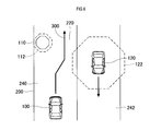
- the recognition unit 24 when the recognition unit 24 recognizes a stationary object 110 such as a road construction place or a parked vehicle as an object that exists in front of the vehicle 100 in the traveling direction, the region setting unit 26 An untravelable area 112 that prohibits entry of the vehicle 100 is set.
- the area setting unit 26 sets an area between the white line 204 having a longer distance from the non-travelable area 112 of the white lines 202 and 204 on both sides of the travel lane 210 and the non-travelable area 112 as the travel permission area 220.
- the travel permission area 220 is an area where the vehicle 100 travels in the travel lane 210 except for the travel impossible area 112.
- the travel setting unit 28 sets the target vehicle speed so that the size of the travel impossible region 112 set by the region setting unit 26 is such that the vehicle 100 can travel in the travel permitted region 220 while avoiding the travel impossible region 112. To do.
- the target vehicle speed By setting the target vehicle speed, the relative speed of the vehicle 100 with respect to objects around the vehicle 100 is adjusted.
- the travel setting unit 28 sets the center position of the travel permission area 220 in the lane width direction along the travel direction of the vehicle 100 as the target travel locus 300 on which the vehicle 100 travels. That is, the target travel locus 300 is set such that the distance between each of the travel impossible area 112 that defines the travel permission region 220 and the white line 204 and the target travel locus 300 is equal.
- the traveling trajectory of the vehicle 100 represents a trajectory in which the position of a specific portion of the vehicle 100 changes in time series as the vehicle 100 travels.
- the specific location of the vehicle 100 is the position of the center of gravity of the vehicle 100, the center of the front end of the vehicle 100 in the vehicle width direction, the center of the rear end of the vehicle 100 in the vehicle width direction, or the like.
- the width of the travel lane 210 is the travel permission area.
- the travel setting unit 28 sets the center position in the width direction of the travel lane 210 along the travel direction of the vehicle 100 as the target travel locus 300 through which the vehicle 100 passes. That is, the target travel locus 300 is set so that the distance between each of the white lines 202 and 204 and the target travel locus 300 is equal.
- the travel setting unit 28 sets the current vehicle speed as the target vehicle speed of the vehicle 100 traveling in the travel permission area 220 when the vehicle 100 can travel in the travel permission area 220 while avoiding the travel prohibition area 112.
- the travel setting unit 28 reduces the target vehicle speed below the current vehicle speed when the vehicle 100 cannot travel in the travel permission region 220 while avoiding the travel disabled region 112.
- the travel setting unit 28 determines that the vehicle 100 can travel in the travel permission area 220 while avoiding the travel impossible area 112.
- the travel setting unit 28 determines that the vehicle 100 cannot travel in the travel permitted area 220 while avoiding the travel disabled area 112 when the width of the travel permitted area 220 in the lane width direction is narrower than the vehicle width of the vehicle 100.
- whether or not the vehicle 100 can travel in the travel permission area 220 may be determined by whether or not the width of the travel permission area 220 in the lane width direction satisfies the following expression (1).
- W1 is the vehicle width of the vehicle 100
- W2 is the width of the travel permission region 220 in the lane width direction
- ⁇ W is a margin for the vehicle 100 to pass through the travel permission region 220.
- the travel setting unit 28 determines that the vehicle 100 can travel in the travel permission area 220 if the width W2 of the travel permission area 220 satisfies the expression (1), and the width W2 of the travel permission area 220 is equal to the expression (1). If not, vehicle 100 determines that it cannot travel in travel permission area 220.
- the region setting unit 26 reduces the non-travelable region 112 when the relative speed of the vehicle 100 with respect to the stationary object 110 decreases.
- the travel-permitted area 220 becomes larger, so that the vehicle 100 can travel in the travel-permitted area 220 while avoiding the travel-unavailable area 112 without entering the travel-unavailable area 112.
- the area setting unit 26 moves in a non-travelable area set around a stationary object such as a road construction site or a parked vehicle, as in other vehicles traveling around the vehicle. It is desirable to make it larger than the untravelable area set around the object. This is because when the stationary object is a movable object such as a parked vehicle, there is a possibility that the movement suddenly starts.
- the travel control unit 30 controls the powertrain system 40, the brake system 42, and the steering system 44 so that the vehicle 100 travels on the target travel locus 300 at the target vehicle speed set by the travel setting unit 28. That is, the traveling control unit 30 controls the vehicle speed and the steering angle of the vehicle.
- the powertrain system 40 controls the opening degree of the throttle device and the fuel injection amount in accordance with the drive output commanded from the travel control unit 30, and the motor is used as the drive source. If it is installed, the power supplied to the motor is controlled.
- the brake system 42 controls an actuator provided in the hydraulic circuit of the hydraulic brake according to the braking force commanded from the traveling control unit 30.
- the brake system 42 controls the power supplied to the motor according to the braking force commanded from the travel control unit 30 to generate the braking force by the regenerative braking. May be.
- the steering system 44 drives the steering handle according to the torque commanded from the travel control unit 30 to steer the vehicle.
- the driving support process executed by the driving support device 20 will be described based on the flowcharts of FIGS. 4 and 5.
- the flowchart of FIG. 4 is always executed at predetermined time intervals.
- control determination unit 22 determines whether or not the output of the support switch 18 is on. When the determination in S400 is No and the support switch 18 is off, the driving support device 20 is prohibited from executing the driving support control, and thus this process ends.
- the travel support device 20 When the determination in S400 is Yes and the support switch 18 is on, the travel support device 20 is permitted to execute the travel support control.
- the recognition unit 24 recognizes an object around the vehicle and a travel path on which the vehicle travels based on detection information acquired from the camera 10 and the millimeter wave radar 12.
- the recognition unit 24 determines whether an object exists around the vehicle. If the determination in S404 is No and there is no object around the vehicle, the travel setting unit 28 determines in S406 based on the recognition result recognized by the recognition unit 24 in the state where no object exists around the vehicle. The target vehicle speed and the target travel locus are set, and the process proceeds to S412.
- the travel setting unit 28 sets, for example, a vehicle speed set in advance by cruise control or the like as the target vehicle speed, and sets the center position in the width direction of the travel path along the travel direction of the vehicle 100 as the target travel locus.
- the area setting unit 26 sets a non-running area forbidding the vehicle around the object. Further, the area setting unit 26 sets an area excluding the travel impossible area on the travel path as a travel permission area in which the vehicle travels.
- the travel setting unit 28 sets the target vehicle speed of the vehicle so that the size of the travel impossible region becomes a size that allows the vehicle to travel in the travel permitted region while avoiding the travel disabled region. Then, a target travel locus of the vehicle traveling in the travel permission area is set. Details of the processing of S410 will be described later.
- the traveling control unit 30 controls the powertrain system 40, the brake system 42, and the steering system 44 based on the target vehicle speed and the target traveling locus set in S406 or S410.
- Target vehicle speed and target travel locus setting process The process executed in S410 of FIG. 4 will be described based on the flowchart of FIG.
- the travel setting unit 28 determines whether there is an area in which the vehicle can travel while avoiding the travel impossible area, that is, whether the vehicle can travel in the travel permitted area.
- the travel setting unit 28 sets the current vehicle speed to the target vehicle speed in S422. And the process proceeds to S426.
- the travel setting unit 28 determines whether to decrease or increase the target vehicle speed from the current vehicle speed. As a result, the relative speed of the vehicle with respect to the object decreases, and the non-running region set around the object becomes small. As a result, the travel permission area increases. After execution of S424, the process proceeds to S426.
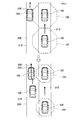
- FIG. 6 An example in which the determination in S420 is No and the vehicle cannot travel in the travel permission area while avoiding the travel unallowable area is shown in the upper part of FIG. 6 and the upper part of FIG.
- the other vehicle 120 is traveling in front of the vehicle 100 in both the left and right adjacent lanes 230 and 234 adjacent to the travel lane 232 of the vehicle 100. Since the vehicle speed of the vehicle 100 is faster than the vehicle speed of the other vehicle 120, the left and right non-travelable regions 122 set by the region setting unit 26 around the other vehicle 120 based on the current relative speed of the vehicle 100 with respect to the other vehicle 120 are There is no area where 100 can avoid and run.
- the travel setting unit 28 decreases the vehicle speed of the vehicle 100 and decreases the relative speed of the vehicle 100 with respect to the other vehicle 120.
- the non-running region 124 set by the region setting unit 26 around the other vehicle 120 is shown in FIG. It becomes smaller than the upper travel impossible area 122.
- a travel permission area 220 is set between the left and right travel impossible areas 124.
- the travel prohibition area 124 is set based on the relative speed of the vehicle 100 with respect to the other vehicle 120 lowered by the travel setting unit 28, and the travel permission area 220 is set between the left and right travel prohibition areas 124. This is the next time S408 in FIG. 4 is executed. Therefore, even if the relative speed of the vehicle 100 with respect to the other vehicle 120 decreases this time, the non-travelable region 112 remains in the upper stage of FIG.
- the travel setting unit 28 sets the travel permission area 220 in the lane width direction along the travel direction of the vehicle 100.
- the center position is set as the target travel locus 300.
- the travel setting unit 28 accelerates the vehicle speed of the vehicle 100 and decreases the relative speed of the vehicle 100 with respect to the other vehicle 120.
- the non-running region 124 set by the region setting unit 26 around the other vehicle 120 as shown in the lower part of FIG. Smaller than.
- the travel permission area 222 is larger than the travel permission area 220.
- the vehicle 100 can travel in the travel permission area 222 while avoiding the travel impossible area 124.
- the travel prohibition area 124 is set based on the reduced relative speed, and the travel permission area 222 larger than the travel permission area 220 is set next time. This is a time when S408 of No. 4 is executed. Therefore, even if the relative speed is decreased this time, the travel impossible area 112 remains in the upper stage of FIG.
- the vehicle 100 may determine that it is not necessary to avoid the other vehicle 120.
- the region setting unit 26 sets the travel permission region 220 of the vehicle 100 based only on the travel impossible region 112 that is set around the stationary object 110 that exists in front of the travel direction of the vehicle 100 in the travel lane 210.
- the travel setting unit 28 sets the center position in the lane width direction along the travel direction of the vehicle 100 in the travel permission area set in S408 of FIG. 4 as the target travel locus. [3. effect] In the embodiment described above, the following effects can be obtained.
- the non-running region is set larger than when the object is moving. Therefore, even if the stationary object moves suddenly, the vehicle 100 avoids the object. Can run.
- the non-travelable region is set larger than when there is no location where it cannot be detected. Thereby, even if another object appears behind the stationary object, the vehicle 100 can travel avoiding the appearing object.
- the camera 10 and the millimeter wave radar 12 correspond to sensors
- the stationary object 110 and the other vehicle 120 correspond to objects around the vehicle
- the traveling lanes 210, 232, and 240 correspond to the vehicles. Corresponds to the traveling road.
- S402 corresponds to the processing as the recognition unit 24
- S408 corresponds to the processing as the region setting unit 26
- S406, S410, and S420 to S426 correspond to the processing as the travel setting unit 28.
- S412 corresponds to the processing as the traveling control unit 30.
- the traveling lane divided by the white line was illustrated as a traveling path where the vehicle 100 drive
- a road surface that is partitioned by a step indicating a boundary between the road and the outside of the road, a non-paved surface, a wall, or the like may be used as the traveling road.
- the driving support device 20 may set the size of the non-driving area according to the type of the object. For example, when the object is a human, the driving support device 20 sets the non-driving region larger than that when the object is not a human.
- the driving support device 20 sets the non-driving regions 122 and 124 around the other vehicle 120 that travels in the adjacent lanes 230 and 234 of the vehicle 100 in the same direction as the vehicle 100. Further, in FIG. 7, the travel support device 20 sets the travel impossible regions 122 and 124 around the other vehicle 120 that travels in the adjacent lane 212 of the vehicle 100 in the same direction as the vehicle 100.
- the driving support device 20 determines that there is no need to travel avoiding the other vehicle 120 that travels in a lane different from the travel lane of the vehicle 100, and does not need to set the travel impossibility region.
- the travel support device 20 may set at least one of the target vehicle speed and the target travel locus of the vehicle so that the vehicle can travel in the travel permission region while avoiding the travel disabled region.
- the vehicle 100 can travel in the travel permission area 220 set based on the current vehicle speed of the vehicle 100. Therefore, the driving support device 20 only needs to set the target travel locus 300 of the vehicle 100 that travels in the travel permission area 220 in order to avoid the stationary object 110 without changing the target vehicle speed.
- the driving support device 20 does not change the target travel locus of the vehicle 100 and sets a travel permission area 220 in which the vehicle 100 can travel by reducing only the target vehicle speed from the current vehicle speed. it can.
- the camera 10 and the millimeter wave radar 12 are used as sensors.
- the sensor may be only one of the camera 10 or the millimeter wave radar 12, for example. Further, as the sensor, another sensor may be added to the camera 10 and the millimeter wave radar 12, or another sensor other than the camera 10 and the millimeter wave radar 12 may be used.
- a plurality of functions of one constituent element in the above embodiment may be realized by a plurality of constituent elements, or a single function of one constituent element may be realized by a plurality of constituent elements.
- a plurality of functions possessed by a plurality of constituent elements may be realized by one constituent element, or a single function realized by a plurality of constituent elements may be realized by one constituent element.
- at least a part of the configuration of the above embodiment may be added to or replaced with the configuration of the other embodiment.
- all the aspects contained in the technical thought specified only by the wording described in the claim are embodiment of this indication.
- a travel support system 2 including the travel support device 20 as a constituent element, a travel support program for causing a computer to function as the travel support device 20, and the travel support program are recorded.
- the present disclosure can also be realized in various forms such as a recording medium and a driving support method.
Landscapes
- Engineering & Computer Science (AREA)
- Transportation (AREA)
- Mechanical Engineering (AREA)
- Automation & Control Theory (AREA)
- Chemical & Material Sciences (AREA)
- Combustion & Propulsion (AREA)
- Physics & Mathematics (AREA)
- General Physics & Mathematics (AREA)
- Human Computer Interaction (AREA)
- Traffic Control Systems (AREA)
- Steering Control In Accordance With Driving Conditions (AREA)
- Control Of Driving Devices And Active Controlling Of Vehicle (AREA)
- Regulating Braking Force (AREA)
Abstract
走行支援装置(20)は、認識部(24、S402)と、領域設定部(26、S408)と、走行設定部(28、S406、S410、S420~S426)と、走行制御部(30、S412)と、を備えている。領域設定部は、認識部が認識する物体に対する車両の相対速度に基づいて、物体の周囲に車両の進入を禁止する走行不可領域(112、122、124)を設定し、さらに走行路において走行不可領域を除いた領域を車両が走行する走行許可領域(220、222)として設定する。走行設定部は、領域設定部が設定する走行許可領域を走行する車両の目標車速と目標走行軌跡とのうち少なくとも一方を設定する。
Description
本国際出願は、2016年4月1日に日本国特許庁に出願された日本国特許出願番号第2016-074264号に基づく優先権を主張するものであり、日本国特許出願番号第2016-074264号の全内容を参照により本国際出願に援用する。
本開示は、周囲の物体を避けて車両を走行させる技術に関する。
車両の周囲に物体が存在する場合、物体との衝突を避けるように車両の走行を制御する技術が知られている。下記特許文献1には、車両の走行方向前方の物体を検出すると、物体の検出点と車両とを結ぶ複数の直線のそれぞれの上に、車両が物体に接近しないように回避点を設定する技術が記載されている。回避点は、物体に対する車両の相対速度が速いほど、より車両側に設定される。
さらに特許文献1には、回避点よりも車両側に仮想白線を設定し、この仮想白線と実際に検出された白線または他の仮想白線とに基づいて、車両が走行する目標車線を推定する技術が記載されている。特許文献1に記載の技術によると、推定した目標車線から逸脱しないように車両の走行が制御されることにより、車両は前方に存在する物体を避けようとしている。
特許文献1に記載の技術によると、仮想直線は、物体の検出点よりも車両側に設定された回避点よりもさらに車両側に設定される。その結果、発明者の詳細な検討により、仮想白線に基づいて推定される目標車線、つまり車両が走行を許可される領域が狭くなるという課題が見出された。
本開示の一態様は、車両の周囲に存在する物体を避けて車両が走行する領域を極力広くする技術を提供できることが望ましい。
本開示の一態様における走行支援装置は、認識部と、領域設定部と、走行設定部と、走行制御部と、を備えている。
本開示の一態様における走行支援装置は、認識部と、領域設定部と、走行設定部と、走行制御部と、を備えている。
認識部は、車両の周囲の物体と車両が走行する走行路とを検出するセンサから取得する検出情報に基づいて、物体と走行路とを認識する。領域設定部は、認識部が認識する物体に対する車両の相対速度に基づいて、物体の周囲に車両の進入を禁止する走行不可領域を設定し、さらに走行路において走行不可領域を除いた領域を車両が走行する走行許可領域として設定する。
走行設定部は、領域設定部が設定する走行許可領域を走行する車両の目標車速と目標走行軌跡とのうち少なくとも一方を設定する。走行制御部は、走行設定部が設定する目標車速と目標走行軌跡とのうち少なくとも一方に基づいて車両の走行を制御する。
この構成によれば、物体の周囲に車両の進入を禁止する走行不可領域を設定し、走行路において走行不可領域を除いた領域を車両が走行する走行許可領域として設定するので、車両が物体を避けて走行する走行許可領域を極力広くすることができる。これにより、物体を避けるように車両の走行を制御するときの自由度が高くなる。
尚、特許請求の範囲に記載した括弧内の符号は、一つの態様として後述する実施形態に記載の具体的手段との対応関係を示すものであって、本開示の技術的範囲を限定するものではない。
以下、本開示の実施形態を図に基づいて説明する。
[1.構成]
図1に示す車載の走行支援システム2は、カメラ10と、ミリ波レーダ12と、操舵角センサ14と、車速センサ16と、支援スイッチ18と、走行支援装置20と、パワートレインシステム40と、ブレーキシステム42と、ステアリングシステム44とを備えている。
[1.構成]
図1に示す車載の走行支援システム2は、カメラ10と、ミリ波レーダ12と、操舵角センサ14と、車速センサ16と、支援スイッチ18と、走行支援装置20と、パワートレインシステム40と、ブレーキシステム42と、ステアリングシステム44とを備えている。
カメラ10は、例えば車両の前方側と後方側とにそれぞれ取り付けられており、車両100の周囲を撮像した画像データを検出情報として走行支援装置20に出力する。
ミリ波レーダ12は、例えば車両の前方側と後方側とにそれぞれ取り付けられており、送信したミリ波が車両の周囲の他車両および歩行者等の物体に反射された反射波を受信するまでの時間に基づいて、物体までの距離を算出する。さらに、反射波の受信方向により車両に対する物体の方位、すなわち角度が定まる。ミリ波レーダ12は、計算した距離と角度とを検出情報として走行支援装置20に出力する。
ミリ波レーダ12は、例えば車両の前方側と後方側とにそれぞれ取り付けられており、送信したミリ波が車両の周囲の他車両および歩行者等の物体に反射された反射波を受信するまでの時間に基づいて、物体までの距離を算出する。さらに、反射波の受信方向により車両に対する物体の方位、すなわち角度が定まる。ミリ波レーダ12は、計算した距離と角度とを検出情報として走行支援装置20に出力する。
尚、ミリ波レーダ12等の電波を照射するレーダに代えて、レーザ光を照射するLIDARを使用してもよい。
操舵角センサ14は車両の操舵角を検出する。車速センサ16は、車両100の車速を検出する。支援スイッチ18は、オンであれば車両が走行路を逸脱しないように走行支援装置20が車両の走行を制御することを許可し、オフであれば走行支援装置20が車両の走行を制御することを禁止する。
操舵角センサ14は車両の操舵角を検出する。車速センサ16は、車両100の車速を検出する。支援スイッチ18は、オンであれば車両が走行路を逸脱しないように走行支援装置20が車両の走行を制御することを許可し、オフであれば走行支援装置20が車両の走行を制御することを禁止する。
走行支援装置20は、CPUと、RAM、ROM、フラッシュメモリ等の半導体メモリとを備えるマイクロコンピュータを搭載している。尚、走行支援装置20は、一つのマイクロコンピュータを搭載してもよいし、複数のマイクロコンピュータを搭載してもよい。
走行支援装置20の各機能は、CPUがROMまたはフラッシュメモリ等の非遷移的実体的記録媒体に記憶されているプログラムを実行することにより実現される。このプログラムが実行されることにより、プログラムに対応する方法が実行される。
走行支援装置20は、CPUがプログラムを実行することで実現される機能の構成として、制御判定部22と、認識部24と、領域設定部26と、走行設定部28と、走行制御部30とを備えている。走行支援装置20を構成するこれらの要素を実現する手法は、ソフトウェアに限るものではなく、一部の要素または全部の要素を、論理回路やアナログ回路等を組み合わせたハードウェアを用いて実現してもよい。
制御判定部22は、支援スイッチ18がオンであれば走行支援装置20が車両の走行を制御することを許可し、オフであれば走行支援装置20が車両の走行を制御することを禁止する。
認識部24は、車両の周囲の物体と、車両が走行する走行路とを検出するカメラ10とミリ波レーダ12とから取得する検出情報に基づいて、車両の周囲の物体と、車両が走行する走行路とを認識する。
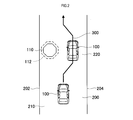
例えば、図2に示すように、認識部24は、カメラ10から取得する車両100の走行方向前方および走行方向後方の画像データに基づいて、車両100が走行する道路200の左右の白線202、204の位置、走行路の幅として白線同士の間隔が示す車線幅、白線の曲率等を算出する。
認識部24は、白線202、204を認識することにより、車両100が走行する走行路として走行車線210を認識する。認識部24は、走行車線210を区画する左右の白線202、204に対する車両100の相対位置、つまり走行車線210の車線幅方向における車両100の位置を、例えば、車両100に対してカメラ10が撮像する白線202、204の角度に基づいて認識する。
また、認識部24は、カメラ10とミリ波レーダ12とから取得する車両100の走行方向前方および走行方向後方の検出情報に基づいて、車両100の周囲に存在する物体を認識する。例えば、認識部24は、車両100が走行する走行車線210に存在する静止物体110と、同じ走行車線210を走行する図示しない他車両と、走行車線210に隣接する隣接車線と対向車線とをそれぞれ走行する図示しない他車両とを認識する。
認識部24は、カメラ10から取得する車両の走行方向前方および走行方向後方の画像データに基づいて、車両100の周囲の物体の位置と、物体の位置の変化量から物体の移動速度とを算出する。また、認識部24は、ミリ波レーダ12から取得する車両100の走行方向前方と走行方向後方との検出情報に基づいて、車両100の周囲の物体の位置と、物体に対する車両の相対速度等を算出する。
物体に対する車両の相対速度は、プラスであれば物体に車両100が近づいて行くことを示し、マイナスであれば物体から車両100が離れて行くことを示している。
領域設定部26は、認識部24が認識する車両の走行車線と車両の周囲の物体の認識結果とに基づいて、物体の周囲に車両の進入を禁止する走行不可領域を設定し、走行路において走行不可領域を除いた領域を車両が走行する走行許可領域として設定する。
領域設定部26は、認識部24が認識する車両の走行車線と車両の周囲の物体の認識結果とに基づいて、物体の周囲に車両の進入を禁止する走行不可領域を設定し、走行路において走行不可領域を除いた領域を車両が走行する走行許可領域として設定する。
例えば、図2に示すように、車両100の走行方向前方に存在する物体として道路工事箇所、駐車車両等の静止物体110を認識部24が認識すると、領域設定部26は、静止物体110の周囲に車両100の進入を禁止する走行不可領域112を設定する。
領域設定部26は、走行車線210の両側の白線202、204のうち走行不可領域112との距離が長い方の白線204と走行不可領域112との間の領域を、走行許可領域220として設定する。走行許可領域220は、走行車線210において走行不可領域112を除いて車両100が走行する領域である。
走行設定部28は、領域設定部26が設定する走行不可領域112の大きさが、車両100が走行不可領域112を避けて走行許可領域220を走行できる大きさになるように、目標車速を設定する。目標車速が設定されることにより、車両100の周囲の物体に対する車両100の相対速度が調整される。
そして、走行設定部28は、車両100の走行方向に沿った車線幅方向における走行許可領域220の中央位置を、車両100が走行する目標走行軌跡300として設定する。つまり、走行許可領域220を区画する走行不可領域112と白線204とのそれぞれと目標走行軌跡300との距離が等しくなるように目標走行軌跡300は設定される。
車両100の走行軌跡は、車両100の走行にしたがって車両100の特定箇所の位置が時系列で変化する軌跡を表している。例えば、車両100の特定箇所は、車両100の重心位置、車両100の前方端部の車幅方向の中央、車両100の後方端部の車幅方向の中央等である。
物体が存在せず走行不可領域112が設定されていない走行車線210では、走行車線210の幅がすべて走行許可領域になる。この場合、走行設定部28は、車両100の走行方向に沿った走行車線210の幅方向の中央位置を、車両100が通る目標走行軌跡300として設定する。つまり、白線202、204のそれぞれと目標走行軌跡300との距離が等しくなるように目標走行軌跡300は設定される。
走行設定部28は、車両100が走行不可領域112を避けて走行許可領域220を走行できる場合、走行許可領域220を走行する車両100の目標車速として現在の車速を設定する。走行設定部28は、車両100が走行不可領域112を避けて走行許可領域220を走行できない場合、現在の車速よりも目標車速を低下させる。
例えば、走行設定部28は、車線幅方向における走行許可領域220の幅が車両100の車幅以上であれば、走行不可領域112を避けて走行許可領域220を車両100が走行できると判定する。走行設定部28は、車線幅方向における走行許可領域220の幅が車両100の車幅よりも狭い場合、走行不可領域112を避けて走行許可領域220を車両100が走行できないと判定する。
ここで、車両100が走行許可領域220を走行できるか否かを、車線幅方向における走行許可領域220の幅が次式(1)を満たすか否かで判定してもよい。式(1)において、W1は車両100の車幅であり、W2は車線幅方向における走行許可領域220の幅であり、ΔWは車両100が走行許可領域220を通過する余裕度である。
W1+ΔW≦W2 ・・・(1)
走行設定部28は、走行許可領域220の幅W2が式(1)を満たせば、車両100は走行許可領域220を走行可能であると判定し、走行許可領域220の幅W2が式(1)を満たさない場合、車両100は走行許可領域220を走行できないと判定する。
走行設定部28は、走行許可領域220の幅W2が式(1)を満たせば、車両100は走行許可領域220を走行可能であると判定し、走行許可領域220の幅W2が式(1)を満たさない場合、車両100は走行許可領域220を走行できないと判定する。
図2において、車両100の車速が低下することにより、静止物体110に対する車両100の相対速度は低下する。図3に示すように、領域設定部26は、静止物体110に対する車両100の相対速度が低下すると走行不可領域112を小さくする。その結果、走行許可領域220が大きくなるので、車両100は、走行不可領域112に進入することなく走行不可領域112を避けて走行許可領域220を走行できる。
尚、領域設定部26は、図3に示すように、道路工事箇所、駐車車両のような静止物体の周囲に設定する走行不可領域を、車両の周囲を走行している他車両のような移動物体の周囲に設定する走行不可領域よりも大きくすることが望ましい。これは、静止物体が駐車車両のように移動可能な物体の場合、急に移動を開始する可能性があるからである。
静止物体が移動を開始するタイミングは認識できない。したがって、車両100が急に移動を開始する静止物体を避けて走行する方が、車両100が移動物体を避けて走行するよりも困難である。
また、静止物体に遮られてカメラ10およびミリ波レーダ12が検出できない箇所がある場合、検出できない箇所がない静止物体よりも走行不可領域を大きく設定することが望ましい。これは、静止物体に遮られてカメラ10およびミリ波レーダ12が検出できない箇所から移動物体が現れる可能性があるからである。
カメラ10およびミリ波レーダ12が検出できない箇所から移動物体が現れることは予測できないので、この移動物体を避けて車両100が走行することは困難である。
走行制御部30は、走行設定部28が設定する目標車速で目標走行軌跡300を車両100が走行するように、パワートレインシステム40と、ブレーキシステム42と、ステアリングシステム44とを制御する。つまり、走行制御部30は、車両の車速と操舵角とを制御する。
走行制御部30は、走行設定部28が設定する目標車速で目標走行軌跡300を車両100が走行するように、パワートレインシステム40と、ブレーキシステム42と、ステアリングシステム44とを制御する。つまり、走行制御部30は、車両の車速と操舵角とを制御する。
パワートレインシステム40は、走行制御部30から指令される駆動出力にしたがって、駆動源として内燃機関を搭載している場合にはスロットル装置の開度および燃料噴射量を制御し、駆動源としてモータを搭載している場合にはモータへの供給電力を制御する。
ブレーキシステム42は、走行制御部30から指令される制動力にしたがって、油圧式ブレーキの液圧回路に設けられたアクチュエータを制御する。車両が駆動源としてモータを搭載している場合には、ブレーキシステム42は、走行制御部30から指令される制動力にしたがって、モータへの供給電力を制御して回生ブレーキによる制動力を生成してもよい。
ステアリングシステム44は、走行制御部30から指令されるトルクにしたがってステアリングハンドルを駆動し、車両を操舵する。
[2.処理]
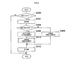
以下、走行支援装置20が実行する走行支援処理を、図4および図5のフローチャートに基づいて説明する。図4のフローチャートは所定時間間隔で常時実行される。
[2.処理]
以下、走行支援装置20が実行する走行支援処理を、図4および図5のフローチャートに基づいて説明する。図4のフローチャートは所定時間間隔で常時実行される。
(1)メイン処理
図4のS400において制御判定部22は、支援スイッチ18の出力がオンであるか否かを判定する。S400の判定がNoであり、支援スイッチ18がオフの場合、走行支援装置20が走行支援制御を実行することは禁止されているので、本処理は終了する。
図4のS400において制御判定部22は、支援スイッチ18の出力がオンであるか否かを判定する。S400の判定がNoであり、支援スイッチ18がオフの場合、走行支援装置20が走行支援制御を実行することは禁止されているので、本処理は終了する。
S400の判定がYesであり、支援スイッチ18がオンの場合、走行支援装置20が走行支援制御を実行することは許可されている。この場合、S402において認識部24は、カメラ10とミリ波レーダ12とから取得する検出情報に基づいて、車両の周囲の物体と、車両が走行する走行路とを認識する。
S404において認識部24は、車両の周囲に物体が存在するか否かを判定する。S404の判定がNoであり、車両の周囲に物体が存在しない場合、S406において走行設定部28は、車両の周囲に物体が存在しない状態で認識部24が認識した認識結果に基づいて、車両の目標車速と目標走行軌跡とを設定し、S412に処理を移行する。
S406において走行設定部28は、例えば、クルーズコントロール等で予め設定された車速を目標車速に設定し、車両100の走行方向に沿った走行路の幅方向の中央位置を目標走行軌跡として設定する。
S404の判定がYesであり、車両の周囲に物体が存在する場合、S408において領域設定部26は、物体の周囲に車両の進入を禁止する走行不可領域を設定する。さらに、領域設定部26は、走行路において走行不可領域を除いた領域を車両が走行する走行許可領域として設定する。
S410において走行設定部28は、走行不可領域の大きさが、車両が走行不可領域を避けて走行許可領域を走行できる大きさになるように、車両の目標車速を設定する。そして、走行許可領域を走行する車両の目標走行軌跡を設定する。S410の処理の詳細は後述される。
S412において走行制御部30は、S406またはS410で設定された目標車速と目標走行軌跡とに基づいて、パワートレインシステム40と、ブレーキシステム42と、ステアリングシステム44とを制御する。
(2)目標車速、目標走行軌跡の設定処理
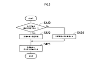
図4のS410で実行される処理について図5のフローチャートに基づいて説明する。
S420において走行設定部28は、車両が走行不可領域を避けて走行可能な領域が存在するか否か、つまり走行許可領域を車両が走行できるか否かを判定する。
図4のS410で実行される処理について図5のフローチャートに基づいて説明する。
S420において走行設定部28は、車両が走行不可領域を避けて走行可能な領域が存在するか否か、つまり走行許可領域を車両が走行できるか否かを判定する。
S420の判定がYesであり、例えば、図2に示すように、車両100が走行不可領域112を避けて走行許可領域220を走行できる場合、走行設定部28は、S422において現在の車速を目標車速に設定し、S426に処理を移行する。
S420の判定がNoであり、車両が走行不可領域を避けて走行許可領域を走行できない場合、S424において走行設定部28は、現在の車速よりも目標車速を低下させるか上昇させるかを決定する。これにより、物体に対する車両の相対速度が低下するので、物体の周囲に設定される走行不可領域は小さくなる。その結果、走行許可領域は大きくなる。S424の実行後、処理はS426に移行する。
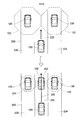
S420の判定がNoであり、車両が走行不可領域を避けて走行許可領域を走行できない例が、図6の上段と図7の上段とに示されている。
図6の上段では、車両100の走行車線232に隣接する左右の隣接車線230、234の両方で車両100の前方を他車両120が走行している。他車両120の車速よりも車両100の車速が速いので、他車両120に対する現在の車両100の相対速度に基づいて領域設定部26が他車両120の周囲に設定する左右の走行不可領域122を車両100が避けて走行できる領域は存在しない。
図6の上段では、車両100の走行車線232に隣接する左右の隣接車線230、234の両方で車両100の前方を他車両120が走行している。他車両120の車速よりも車両100の車速が速いので、他車両120に対する現在の車両100の相対速度に基づいて領域設定部26が他車両120の周囲に設定する左右の走行不可領域122を車両100が避けて走行できる領域は存在しない。
そこで、走行設定部28は、車両100の車速を低下させ、他車両120に対する車両100の相対速度を低下させる。低下させた相対速度に基づいて図4のS408が実行されることにより、図6の下段に示すように、領域設定部26が他車両120の周囲に設定する走行不可領域124は、図6の上段の走行不可領域122よりも小さくなる。その結果、左右の走行不可領域124の間に走行許可領域220が設定される。
ただし、走行設定部28が低下させた他車両120に対する車両100の相対速度に基づいて走行不可領域124が設定され、左右の走行不可領域124の間に走行許可領域220が設定されるのは、次回、図4のS408が実行されるときである。したがって、今回、他車両120に対する車両100の相対速度が低下しても、走行不可領域112は図6の上段のままである。
走行設定部28は、走行不可領域124が設定され、左右の走行不可領域124の間に走行許可領域220が設定されると、車両100の走行方向に沿った車線幅方向における走行許可領域220の中央位置を目標走行軌跡300として設定する。
また、図7の上段では、車両100の走行車線210に隣接する右側の隣接車線212において、車両100の後方から他車両120が車両100に接近している。現在の相対速度では、他車両120が車両100を追い越すときに、領域設定部26が他車両120の周囲に設定する走行不可領域122を避けて車両100は走行許可領域220を走行できない。
そこで、走行設定部28は、車両100の車速を加速し、他車両120に対する車両100の相対速度を低下させる。低下させた相対速度に基づいて図4のS408が実行されることにより、図7の下段に示すように、領域設定部26が他車両120の周囲に設定する走行不可領域124は走行不可領域122よりも小さくなる。その結果、走行許可領域222は走行許可領域220よりも大きくなる。
これにより、他車両120が車両100を追い越すときに、車両100は走行不可領域124を避けて走行許可領域222を走行できる。
図6の場合と同様に、図7においても、低下させた相対速度に基づいて走行不可領域124が設定され、走行許可領域220よりも大きい走行許可領域222が設定されるのは、次回、図4のS408が実行されるときである。したがって、今回相対速度を低下させても、走行不可領域112は図7の上段のままである。
図6の場合と同様に、図7においても、低下させた相対速度に基づいて走行不可領域124が設定され、走行許可領域220よりも大きい走行許可領域222が設定されるのは、次回、図4のS408が実行されるときである。したがって、今回相対速度を低下させても、走行不可領域112は図7の上段のままである。
ここで、図8に示すように、車両100が走行している走行車線240の対向車線242を他車両120が走行している場合、車両100と他車両120とは異なる車線を走行しているので、車両100は他車両120を避ける必要はないと判断してもよい。
この判断に基づけば、他車両120に対する車両100の相対速度に基づいて他車両120の周囲に設定される走行不可領域122が車両100の走行車線210に進入するとしても、走行不可領域122を無視できる。
したがって、領域設定部26は、走行車線210において車両100の走行方向前方に存在する静止物体110の周囲に設定する走行不可領域112だけに基づいて、車両100の走行許可領域220を設定する。
S426において走行設定部28は、図4のS408で設定した走行許可領域の車両100の走行方向に沿った車線幅方向における中央位置を目標走行軌跡として設定する。
[3.効果]
以上説明した上記実施形態では、以下の効果を得ることができる。
[3.効果]
以上説明した上記実施形態では、以下の効果を得ることができる。
(1)走行路において、物体の周囲に設定した車両100の進入を禁止する走行不可領域を除いた領域が車両100が走行する走行許可領域として設定されるので、車両100が物体を避けて走行する走行許可領域を極力広くすることができる。これにより、物体を避けるように車両100の走行を制御するときの自由度が高くなる。
(2)車両100が走行不可領域を避けて走行許可領域を走行できない場合、相対速度が低下するように車両100の目標車速を設定するという簡単な制御により、車両100は容易に物体を避けて走行できる。
(3)物体が静止している場合、物体が移動している場合よりも走行不可領域が大きく設定されるので、静止している物体が急に移動しても、車両100は物体を避けて走行できる。
(4)静止物体に遮られてカメラ10とミリ波レーダ12とが検出できない箇所が存在する場合、検出できない箇所が存在しない場合よりも走行不可領域は大きく設定される。これにより、静止物体の陰から他の物体が現れても、車両100は現れた物体を避けて走行できる。
以上説明した上記実施形態において、カメラ10とミリ波レーダ12とがセンサに対応し、静止物体110と他車両120とが車両の周囲の物体に対応し、走行車線210、232、240が車両が走行する走行路に対応する。
また、上記実施形態において、S402が認識部24としての処理に対応し、S408が領域設定部26としての処理に対応し、S406、S410、S420~S426が走行設定部28としての処理に対応し、S412が走行制御部30としての処理に対応する。
[4.他の実施形態]
(1)上記実施形態では、車両100が走行する走行路として、白線で区画された走行車線が例示された。白線がない道路の場合には、道路と道路の外側との境界を示す段差、非舗装面、壁等により区画される路面を走行路としてもよい。
(1)上記実施形態では、車両100が走行する走行路として、白線で区画された走行車線が例示された。白線がない道路の場合には、道路と道路の外側との境界を示す段差、非舗装面、壁等により区画される路面を走行路としてもよい。
(2)走行支援装置20は、物体の種別に応じて走行不可領域の大きさを設定してもよい。例えば、物体が人間の場合、走行支援装置20は、人間以外の場合よりも走行不可領域を大きく設定する。
(3)走行支援装置20は、図6においては、車両100と同じ方向に車両100の隣接車線230、234を走行する他車両120の周囲に走行不可領域122、124を設定した。また、走行支援装置20は、図7においては、車両100と同じ方向に車両100の隣接車線212を走行する他車両120の周囲に走行不可領域122、124を設定した。
これに対し、走行支援装置20は、車両100の走行車線と異なる車線を走行する他車両120を避けて走行する必要はないと判断し、走行不可領域を設定しなくてもよい。
(4)走行支援装置20は、車両が走行不可領域を避けて走行許可領域を走行できるようにするために、車両の目標車速と目標走行軌跡とのうち少なくとも一方を設定すればよい。
(4)走行支援装置20は、車両が走行不可領域を避けて走行許可領域を走行できるようにするために、車両の目標車速と目標走行軌跡とのうち少なくとも一方を設定すればよい。
例えば、図2においては、車両100の現在の車速に基づいて設定された走行許可領域220を車両100は走行できる。したがって、走行支援装置20は、目標車速を変更することなく、静止物体110を避けるために走行許可領域220を走行する車両100の目標走行軌跡300だけを設定すればよい。
また、図6においては、走行支援装置20は、車両100の目標走行軌跡は変更せず、目標車速だけを現在の車速よりも低下させることにより、車両100が走行可能な走行許可領域220を設定できる。
(5)上記実施形態では、カメラ10とミリ波レーダ12とをセンサして使用した。これに対し、センサは、例えばカメラ10またはミリ波レーダ12の一方だけでもよい。また、センサとして、カメラ10とミリ波レーダ12とに他のセンサを加えてもよいし、カメラ10とミリ波レーダ12と以外の他のセンサを使用してもよい。
(6)上記実施形態における一つの構成要素が有する複数の機能を複数の構成要素によって実現したり、一つの構成要素が有する一つの機能を複数の構成要素によって実現したりしてもよい。また、複数の構成要素が有する複数の機能を一つの構成要素によって実現したり、複数の構成要素によって実現される一つの機能を一つの構成要素によって実現したりしてもよい。また、上記実施形態の構成の一部を省略してもよい。また、上記実施形態の構成の少なくとも一部を、他の上記実施形態の構成に対して付加又は置換してもよい。尚、特許請求の範囲に記載した文言のみによって特定される技術思想に含まれるあらゆる態様が本開示の実施形態である。
(7)上述した走行支援装置20の他、当該走行支援装置20を構成要素とする走行支援システム2、当該走行支援装置20としてコンピュータを機能させるための走行支援プログラム、この走行支援プログラムを記録した記録媒体、走行支援方法など、種々の形態で本開示を実現することもできる。
Claims (10)
- 走行支援装置(20)であって、
車両(100)の周囲の物体(110、120)と前記車両が走行する走行路(210、232、240)とを検出するセンサ(10、12)から取得する検出情報に基づいて、前記物体と前記走行路とを認識するように構成された認識部(24、S402)と、
前記認識部が認識する前記物体に対する前記車両の相対速度に基づいて、前記物体の周囲に前記車両の進入を禁止する走行不可領域(112、122、124)を設定し、さらに前記走行路において前記走行不可領域を除いた領域を前記車両が走行する走行許可領域(220、222)として設定するように構成された領域設定部(26、S408)と、
前記領域設定部が設定する前記走行許可領域を走行する前記車両の目標車速と目標走行軌跡とのうち少なくとも一方を設定するように構成された走行設定部(28、S406、S410、S420~S426)と、
前記走行設定部が設定する前記目標車速と前記目標走行軌跡とのうち少なくとも一方に基づいて前記車両の走行を制御するように構成された走行制御部(30、S412)と、を備える走行支援装置。 - 請求項1に記載の走行支援装置であって、
前記領域設定部は、前記相対速度が速いほど前記走行不可領域を大きく設定し、前記相対速度が遅いほど前記走行不可領域を小さく設定するように構成されている、
走行支援装置。 - 請求項2に記載の走行支援装置であって、
前記走行設定部は、前記領域設定部が前記相対速度に基づいて設定する前記走行不可領域の大きさが、前記車両が前記走行不可領域を避けて前記走行許可領域を走行できる大きさになるように、前記目標車速を設定して前記相対速度を調整するように構成されている、
走行支援装置。 - 請求項1から3のいずれか一項に記載の走行支援装置であって、
前記認識部は前記物体が移動しているか静止しているかを認識するように構成され、
前記領域設定部は、前記物体が静止している場合、前記物体が移動している場合よりも前記走行不可領域を大きく設定するように構成されている、
走行支援装置。 - 請求項4に記載の走行支援装置であって、
前記領域設定部は、静止している前記物体に遮られて前記センサが検出できない箇所が存在すると前記認識部が認識すると、前記箇所が存在しない場合よりも静止している前記物体の周囲に設定する前記走行不可領域を大きくするように構成されている、
走行支援装置。 - 請求項1から5のいずれか一項に記載の走行支援装置であって、
前記走行設定部(S424)は、前記車両が走行方向前方の前記走行不可領域を避けて走行できない場合、走行方向前方の前記走行不可領域が小さくなるように前記車両の現在の車速よりも前記目標車速を低下させるように構成されている、
走行支援装置。 - 請求項1から6のいずれか一項に記載の走行支援装置であって、
前記走行設定部(S424)は、前記領域設定部により前記走行不可領域を設定された他車両が前記車両の走行方向後方から前記車両に接近し、走行方向後方から接近してくる前記他車両の周囲に設定された前記走行不可領域を避けて前記車両が走行できない場合、前記走行不可領域が小さくなるように前記車両の現在の車速よりも前記目標車速を上昇させるように構成されている、
走行支援装置。 - 請求項1から7のいずれか一項に記載の走行支援装置であって、
前記領域設定部は、前記走行路に少なくとも一部が存在する前記物体に対して前記走行不可領域を設定し、前記走行路の外側に存在する前記物体に対して前記走行不可領域を設定しないように構成されている、
走行支援装置。 - 請求項1から8のいずれか一項に記載の走行支援装置であって、
前記認識部は前記センサが検出する白線に基づいて前記走行路として前記車両が走行する走行車線を認識するように構成されている、
走行支援装置。 - 請求項1から9のいずれか一項に記載の走行支援装置であって、
前記走行設定部は、前記車両の走行方向に沿った前記走行路の幅方向における前記走行許可領域の中央位置を前記目標走行軌跡として設定するように構成されている、
走行支援装置。
Priority Applications (1)
| Application Number | Priority Date | Filing Date | Title |
|---|---|---|---|
| US16/089,988 US10661794B2 (en) | 2016-04-01 | 2017-03-29 | Driving assistance device |
Applications Claiming Priority (2)
| Application Number | Priority Date | Filing Date | Title |
|---|---|---|---|
| JP2016074264A JP6668895B2 (ja) | 2016-04-01 | 2016-04-01 | 走行支援装置 |
| JP2016-074264 | 2016-04-01 |
Publications (1)
| Publication Number | Publication Date |
|---|---|
| WO2017170766A1 true WO2017170766A1 (ja) | 2017-10-05 |
Family
ID=59964673
Family Applications (1)
| Application Number | Title | Priority Date | Filing Date |
|---|---|---|---|
| PCT/JP2017/013054 Ceased WO2017170766A1 (ja) | 2016-04-01 | 2017-03-29 | 走行支援装置 |
Country Status (3)
| Country | Link |
|---|---|
| US (1) | US10661794B2 (ja) |
| JP (1) | JP6668895B2 (ja) |
| WO (1) | WO2017170766A1 (ja) |
Cited By (5)
| Publication number | Priority date | Publication date | Assignee | Title |
|---|---|---|---|---|
| EP3725629A1 (en) * | 2019-04-19 | 2020-10-21 | Mazda Motor Corporation | Vehicle control device |
| EP3725628A1 (en) * | 2019-04-19 | 2020-10-21 | Mazda Motor Corporation | Vehicle control device |
| EP3725630A1 (en) * | 2019-04-19 | 2020-10-21 | Mazda Motor Corporation | Vehicle control device |
| EP3730368A1 (en) * | 2019-04-24 | 2020-10-28 | Mazda Motor Corporation | Vehicle control device, method and computer program product |
| EP3730367A1 (en) * | 2019-04-24 | 2020-10-28 | Mazda Motor Corporation | Vehicle control device, method and computer program product |
Families Citing this family (15)
| Publication number | Priority date | Publication date | Assignee | Title |
|---|---|---|---|---|
| CN108137045B (zh) * | 2015-10-16 | 2021-07-06 | 日立汽车系统株式会社 | 车辆控制系统、车辆控制装置 |
| JP6668895B2 (ja) * | 2016-04-01 | 2020-03-18 | 株式会社デンソー | 走行支援装置 |
| JP7030117B2 (ja) * | 2017-06-15 | 2022-03-04 | ヴィオニア スウェーデン エービー | 運転支援装置、運転支援方法及びコンピュータプログラム |
| JP2019142303A (ja) * | 2018-02-19 | 2019-08-29 | マツダ株式会社 | 車両制御装置 |
| US11353872B2 (en) * | 2018-07-30 | 2022-06-07 | Pony Ai Inc. | Systems and methods for selectively capturing and filtering sensor data of an autonomous vehicle |
| US11110922B2 (en) * | 2018-11-05 | 2021-09-07 | Zoox, Inc. | Vehicle trajectory modification for following |
| JP7215391B2 (ja) * | 2019-10-15 | 2023-01-31 | トヨタ自動車株式会社 | 自動運転車両の車両制御システム及び車両制御装置 |
| WO2021234427A1 (ja) * | 2020-05-22 | 2021-11-25 | 日産自動車株式会社 | 走行支援方法及び走行支援装置 |
| KR20220064470A (ko) * | 2020-11-11 | 2022-05-19 | 현대자동차주식회사 | 교차로 대향차 충돌방지 보조 장치 및 그 방법 |
| JP7367660B2 (ja) * | 2020-11-24 | 2023-10-24 | トヨタ自動車株式会社 | 運転支援システム |
| JP7590863B2 (ja) * | 2020-12-21 | 2024-11-27 | イビデン株式会社 | エレクトレットの製造方法 |
| US11891061B2 (en) * | 2021-06-17 | 2024-02-06 | Ford Global Technologies, Llc | Target vehicle detection |
| KR20240025632A (ko) * | 2021-08-25 | 2024-02-27 | 우이시 테크놀로지스 (베이징) 리미티드. | 차량 의사결정 계획 방법, 장치, 기기 및 매체 |
| JP7635106B2 (ja) * | 2021-09-30 | 2025-02-25 | 本田技研工業株式会社 | 運転支援装置、運転支援方法、およびプログラム |
| JP7768164B2 (ja) * | 2023-02-15 | 2025-11-12 | トヨタ自動車株式会社 | 車両制御装置 |
Citations (4)
| Publication number | Priority date | Publication date | Assignee | Title |
|---|---|---|---|---|
| JPH0261798A (ja) * | 1988-08-26 | 1990-03-01 | Fujitsu Ten Ltd | 車間距離制御装置 |
| JP2003205764A (ja) * | 2002-01-16 | 2003-07-22 | Nissan Motor Co Ltd | 車両用走行制御装置 |
| JP2007257519A (ja) * | 2006-03-24 | 2007-10-04 | Mazda Motor Corp | 車両用走行支援装置 |
| JP2015203972A (ja) * | 2014-04-14 | 2015-11-16 | 株式会社日本自動車部品総合研究所 | 走行経路生成装置 |
Family Cites Families (15)
| Publication number | Priority date | Publication date | Assignee | Title |
|---|---|---|---|---|
| JP3477142B2 (ja) * | 2000-03-29 | 2003-12-10 | 三菱電機株式会社 | Dsrc車載器 |
| JP2002061789A (ja) * | 2000-08-17 | 2002-02-28 | Ishikawajima Harima Heavy Ind Co Ltd | マルチストレーナ |
| JP4654796B2 (ja) * | 2005-06-29 | 2011-03-23 | トヨタ自動車株式会社 | 車両用運転支援装置 |
| ITTO20060214A1 (it) * | 2006-03-22 | 2007-09-23 | Kria S R L | Sistema di rilevamento di veicoli |
| US8744692B2 (en) * | 2007-11-30 | 2014-06-03 | Volvo Lastvagnar Ab | Method of identifying positions of wheel modules |
| JP5896505B2 (ja) * | 2010-12-17 | 2016-03-30 | アルパイン株式会社 | 車両運転支援装置 |
| US10089537B2 (en) * | 2012-05-18 | 2018-10-02 | Magna Electronics Inc. | Vehicle vision system with front and rear camera integration |
| CN104685866B (zh) * | 2012-07-27 | 2018-12-14 | 歌乐株式会社 | 三维物体检测装置以及三维物体检测方法 |
| JP6052865B2 (ja) * | 2012-10-29 | 2016-12-27 | アルパイン株式会社 | 車載表示制御装置および車載表示制御方法 |
| US8868328B1 (en) * | 2013-06-04 | 2014-10-21 | The Boeing Company | System and method for routing decisions in a separation management system |
| US9448250B2 (en) * | 2013-06-08 | 2016-09-20 | Apple Inc. | Detecting mount angle of mobile device in vehicle using motion sensors |
| US9988047B2 (en) * | 2013-12-12 | 2018-06-05 | Magna Electronics Inc. | Vehicle control system with traffic driving control |
| JP6264457B2 (ja) * | 2014-06-25 | 2018-01-24 | 日産自動車株式会社 | 車両制御装置 |
| JP6668895B2 (ja) * | 2016-04-01 | 2020-03-18 | 株式会社デンソー | 走行支援装置 |
| JP6380919B2 (ja) * | 2016-09-01 | 2018-08-29 | マツダ株式会社 | 車両制御装置 |
-
2016
- 2016-04-01 JP JP2016074264A patent/JP6668895B2/ja active Active
-
2017
- 2017-03-29 US US16/089,988 patent/US10661794B2/en active Active
- 2017-03-29 WO PCT/JP2017/013054 patent/WO2017170766A1/ja not_active Ceased
Patent Citations (4)
| Publication number | Priority date | Publication date | Assignee | Title |
|---|---|---|---|---|
| JPH0261798A (ja) * | 1988-08-26 | 1990-03-01 | Fujitsu Ten Ltd | 車間距離制御装置 |
| JP2003205764A (ja) * | 2002-01-16 | 2003-07-22 | Nissan Motor Co Ltd | 車両用走行制御装置 |
| JP2007257519A (ja) * | 2006-03-24 | 2007-10-04 | Mazda Motor Corp | 車両用走行支援装置 |
| JP2015203972A (ja) * | 2014-04-14 | 2015-11-16 | 株式会社日本自動車部品総合研究所 | 走行経路生成装置 |
Cited By (8)
| Publication number | Priority date | Publication date | Assignee | Title |
|---|---|---|---|---|
| EP3725629A1 (en) * | 2019-04-19 | 2020-10-21 | Mazda Motor Corporation | Vehicle control device |
| EP3725628A1 (en) * | 2019-04-19 | 2020-10-21 | Mazda Motor Corporation | Vehicle control device |
| EP3725630A1 (en) * | 2019-04-19 | 2020-10-21 | Mazda Motor Corporation | Vehicle control device |
| CN111824088A (zh) * | 2019-04-19 | 2020-10-27 | 马自达汽车株式会社 | 车辆控制装置 |
| CN111824089A (zh) * | 2019-04-19 | 2020-10-27 | 马自达汽车株式会社 | 车辆控制装置 |
| JP7497789B2 (ja) | 2019-04-19 | 2024-06-11 | マツダ株式会社 | 車両制御装置 |
| EP3730368A1 (en) * | 2019-04-24 | 2020-10-28 | Mazda Motor Corporation | Vehicle control device, method and computer program product |
| EP3730367A1 (en) * | 2019-04-24 | 2020-10-28 | Mazda Motor Corporation | Vehicle control device, method and computer program product |
Also Published As
| Publication number | Publication date |
|---|---|
| US20190118809A1 (en) | 2019-04-25 |
| JP2017187844A (ja) | 2017-10-12 |
| US10661794B2 (en) | 2020-05-26 |
| JP6668895B2 (ja) | 2020-03-18 |
Similar Documents
| Publication | Publication Date | Title |
|---|---|---|
| WO2017170766A1 (ja) | 走行支援装置 | |
| US10676093B2 (en) | Vehicle control system, vehicle control method, and storage medium | |
| JP6493272B2 (ja) | 走行支援装置 | |
| JP6152673B2 (ja) | 車線変更支援装置 | |
| CN108622088B (zh) | 碰撞避免装置 | |
| CN108778886B (zh) | 行驶辅助装置 | |
| JP7119428B2 (ja) | 運転支援装置 | |
| JP2009078733A (ja) | 走行支援装置 | |
| JP2019043313A (ja) | 車両制御装置 | |
| JP7497789B2 (ja) | 車両制御装置 | |
| JP6350385B2 (ja) | 運転支援装置 | |
| CN107000745A (zh) | 车辆的行驶控制装置以及行驶控制方法 | |
| JP2017100681A (ja) | 走行制御装置 | |
| WO2013186925A1 (ja) | 追従制御装置 | |
| WO2016052586A1 (ja) | 運転支援装置 | |
| JP2007269312A (ja) | 車両用運転操作補助装置 | |
| JP2023105692A (ja) | 車両の運転支援装置 | |
| JP6535537B2 (ja) | 車両の運転支援装置 | |
| WO2023054195A1 (ja) | 車両制御装置及び車両制御プログラム | |
| US12304465B2 (en) | Driving assistance device, driving assistance method, and storage medium | |
| JP7619921B2 (ja) | 車両衝突回避支援装置及び車両衝突回避支援プログラム | |
| JP7845336B2 (ja) | 車両の制御装置及び、制御方法 | |
| JP2022018853A (ja) | 移動体制御装置 | |
| JP7304378B2 (ja) | 運転支援装置、運転支援方法、およびプログラム | |
| CN110576858B (zh) | 车辆控制装置、车辆控制方法和记录介质 |
Legal Events
| Date | Code | Title | Description |
|---|---|---|---|
| NENP | Non-entry into the national phase |
Ref country code: DE |
|
| 121 | Ep: the epo has been informed by wipo that ep was designated in this application |
Ref document number: 17775300 Country of ref document: EP Kind code of ref document: A1 |
|
| 122 | Ep: pct application non-entry in european phase |
Ref document number: 17775300 Country of ref document: EP Kind code of ref document: A1 |