WO2017169410A1 - Échangeur de chaleur - Google Patents
Échangeur de chaleur Download PDFInfo
- Publication number
- WO2017169410A1 WO2017169410A1 PCT/JP2017/007273 JP2017007273W WO2017169410A1 WO 2017169410 A1 WO2017169410 A1 WO 2017169410A1 JP 2017007273 W JP2017007273 W JP 2017007273W WO 2017169410 A1 WO2017169410 A1 WO 2017169410A1
- Authority
- WO
- WIPO (PCT)
- Prior art keywords
- plate fin
- flow path
- plate
- header
- region
- Prior art date
Links
Images


Classifications
-
- F—MECHANICAL ENGINEERING; LIGHTING; HEATING; WEAPONS; BLASTING
- F28—HEAT EXCHANGE IN GENERAL
- F28D—HEAT-EXCHANGE APPARATUS, NOT PROVIDED FOR IN ANOTHER SUBCLASS, IN WHICH THE HEAT-EXCHANGE MEDIA DO NOT COME INTO DIRECT CONTACT
- F28D1/00—Heat-exchange apparatus having stationary conduit assemblies for one heat-exchange medium only, the media being in contact with different sides of the conduit wall, in which the other heat-exchange medium is a large body of fluid, e.g. domestic or motor car radiators
- F28D1/02—Heat-exchange apparatus having stationary conduit assemblies for one heat-exchange medium only, the media being in contact with different sides of the conduit wall, in which the other heat-exchange medium is a large body of fluid, e.g. domestic or motor car radiators with heat-exchange conduits immersed in the body of fluid
- F28D1/03—Heat-exchange apparatus having stationary conduit assemblies for one heat-exchange medium only, the media being in contact with different sides of the conduit wall, in which the other heat-exchange medium is a large body of fluid, e.g. domestic or motor car radiators with heat-exchange conduits immersed in the body of fluid with plate-like or laminated conduits
-
- F—MECHANICAL ENGINEERING; LIGHTING; HEATING; WEAPONS; BLASTING
- F28—HEAT EXCHANGE IN GENERAL
- F28D—HEAT-EXCHANGE APPARATUS, NOT PROVIDED FOR IN ANOTHER SUBCLASS, IN WHICH THE HEAT-EXCHANGE MEDIA DO NOT COME INTO DIRECT CONTACT
- F28D9/00—Heat-exchange apparatus having stationary plate-like or laminated conduit assemblies for both heat-exchange media, the media being in contact with different sides of a conduit wall
- F28D9/0062—Heat-exchange apparatus having stationary plate-like or laminated conduit assemblies for both heat-exchange media, the media being in contact with different sides of a conduit wall the conduits for one heat-exchange medium being formed by spaced plates with inserted elements
-
- F—MECHANICAL ENGINEERING; LIGHTING; HEATING; WEAPONS; BLASTING
- F28—HEAT EXCHANGE IN GENERAL
- F28F—DETAILS OF HEAT-EXCHANGE AND HEAT-TRANSFER APPARATUS, OF GENERAL APPLICATION
- F28F3/00—Plate-like or laminated elements; Assemblies of plate-like or laminated elements
- F28F3/08—Elements constructed for building-up into stacks, e.g. capable of being taken apart for cleaning
Definitions
- the present disclosure relates to a heat exchanger, and more particularly, to a heat exchanger for stacked plate fins configured by stacking plate-shaped plate fins through which a refrigerant flows.
- a heat exchanger used for exchanging heat energy between fluids having different heat energy is used in many devices.
- heat exchangers of laminated plate fins are widely used in, for example, home and vehicle air conditioners, computers, and various electric devices.
- the heat exchanger for stacked plate fins exchanges heat between the fluid (refrigerant) that flows through the flow path formed in the plate-shaped plate fins and the fluid (air) that flows between the stacked plate fins. It is a form to do.
- plate fins In the field of heat exchangers, it is advantageous to form plate fins with a material having a small thickness and high thermal conductivity in terms of reducing weight, size, and efficiency, but there is a problem in terms of reliability. There was a risk of having.
- the flow path of the refrigerant in the plate fin is deformed, resulting in variations in the flow rate and flow rate of the refrigerant.
- the performance as a heat exchanger may be deteriorated.
- the present disclosure aims to provide a heat exchanger that achieves weight reduction, size reduction, and efficiency of heat exchange, and that is highly reliable even in a configuration in which a high-pressure refrigerant flows.
- a plate fin stack in which plate fins having a flow path through which a first fluid flows is stacked, and the first fluid flowing through the flow path of each plate fin in the plate fin stack passes. And a supply and discharge pipe, and a second fluid is allowed to flow between the stacks of the plate fin stacks to exchange heat between the first fluid and the second fluid.
- the plate fin is a header flow that communicates a flow path region having a plurality of linear first fluid flow paths and each first fluid flow path of the flow path area and a supply / discharge pipe so that the first fluid flows in parallel.
- a header area having a path.
- the outer wall of the header channel is in contact with the outer wall of the header channel of the plate fin adjacent in the stacking direction in the plate fin stack.
- the perspective view which shows the external appearance of the laminated plate fin heat exchanger of embodiment which concerns on this indication The top view which shows the plate fin in the laminated plate fin heat exchanger of this embodiment Exploded view showing a part of the structure of the plate fin in the laminated plate fin heat exchanger of the present embodiment.
- the top view which shows a part of plate fin in the plate fin laminated body in the laminated plate fin heat exchanger of this embodiment
- the top view of the plate fin which shows the modification of embodiment concerning this indication The top view of the plate fin which shows the modification of embodiment concerning this indication
- the top view of the plate fin which shows the modification of embodiment concerning this indication The perspective view which shows the upper end plate provided in the upper end of the plate fin laminated body in this embodiment
- a heat exchanger includes a plate fin laminate in which plate fins having flow paths through which a first fluid flows are stacked, and a first fluid that flows through the flow path of each plate fin in the plate fin stack.
- the second fluid is caused to flow between the stacks of the plate fin stacks to exchange heat between the first fluid and the second fluid.
- the plate fin is a header flow that communicates a flow path region having a plurality of linear first fluid flow paths and each first fluid flow path of the flow path area and a supply / discharge pipe so that the first fluid flows in parallel.
- the outer wall of the header channel is in contact with the outer wall of the header channel of the plate fin adjacent in the stacking direction in the plate fin stack.
- the header flow path in the first aspect is a multi-branch flow path for allowing the refrigerant passing through the supply / discharge pipe to flow through the first fluid flow paths in the flow path region. You may have.
- a heat exchanger is configured in the second aspect such that the multi-branch channel is in contact with the outer wall of the multi-branch channel in the plate fin adjacent in the stacking direction in the plate fin stack. May be.
- the pipe wall of the header channel may be formed thicker than the other part in the header region of any one of the first to third aspects.
- the tube wall of the flow path may be formed thicker than other parts in the flow path region of any one of the first to fourth aspects.
- a heat exchanger is the plate fin according to any one of the first to fifth aspects, wherein the header regions are provided on both sides, and the header flow paths in the header regions on both sides are symmetrical. It may be configured to have a typical shape.
- a heat exchanger is the sixth aspect according to the sixth aspect, in which the header flow path communicates between the supply / discharge pipe and the multi-branch flow path in the plate fins in which the header regions are provided on both sides.
- the bypass channel and the multi-branch channel including the bypass channel and disposed on both sides of the plate fin may be configured to have a point-symmetric shape with the center of the plate fin as the center of symmetry.
- a heat exchanger includes a plurality of protruding fins that differ from the flow path in the header region in the plate fin in which the header region of any one of the first to seventh aspects is provided on both sides.
- the header region support portions formed on the both sides of the plate fins may be configured to have a point-symmetric shape with the center of the plate fin as the center of symmetry.
- the header region is provided on one end side, and the supply / discharge pipe corresponds to the header region. It is good also as a structure provided in the position.
- a plurality of header region support portions that are different from the flow path are formed in the header region of the plate fin of any one of the first to ninth aspects,
- the header region support portion may be configured to contact a header region of an adjacent plate fin in the stacking direction in the plate fin stack to form a predetermined space between the adjacent plate fins in the stacking direction.
- the heat exchanger of the eleventh aspect according to the present disclosure may be configured such that the header region support portion provided in the header region of the tenth aspect has a through hole, and the through hole becomes a positioning hole. .
- the heat exchanger according to the twelfth aspect of the present disclosure may have a configuration in which a positioning pin is fixed to the positioning hole according to the eleventh aspect.
- a protruding flow path region support portion that is different from the flow path is formed in the flow path region of the plate fin.
- the flow channel region support portion may be configured to contact a flow channel region of the plate fin adjacent in the stacking direction in the plate fin laminate to form a predetermined space between the stacks.
- the plate fin laminate is configured by laminating plate fins having different flow channel shapes. Also good.
- the plate fin stack is formed by alternately stacking plate fins having two types of flow paths. May be configured.
- the heat exchanger according to the sixteenth aspect of the present disclosure includes a plate fin laminate according to the fifteenth aspect in which the flow in the plate fins that are alternately laminated in a cross section perpendicular to the direction in which the first fluid flows in the flow path region.
- the road may be configured in a staggered arrangement.
- the heat exchanger of the seventeenth aspect is configured such that a flow path support portion that protrudes different from the flow path is formed in the flow path region of the plate fin, and the flow path support portion is a plate. You may comprise so that it may contact
- the flow path support portion protruding from the plate fin of the seventeenth aspect is in a flow direction of the second fluid flowing between the laminations of the plate fin laminate. They may be arranged in a staggered arrangement.
- the number of flow path support portions projecting from the plate fins of the seventeenth aspect is provided more on the leeward side than on the leeward side in the flow direction of the second fluid B. May be.
- a heat exchanger is the plate fin having the two kinds of flow path shapes according to the fifteenth aspect, wherein the flow path area of one of the plate fins is different from the flow path. Is formed in the flow channel region of the other plate fin at a position corresponding to the flow channel region convex portion, and the flow channel region convex portion of the plate fin adjacent in the stacking direction in the plate fin laminate. And the channel region recess may be engaged so that a predetermined space is maintained between the stacked plate fins adjacent to each other.
- the flow path of at least the flow path region of the plate fin flows in the direction in which the first fluid flows in the flow path.
- the cross section orthogonal to may be rectangular.
- the flow path of at least the flow path region in the plate fin flows in the direction in which the first fluid flows in the flow path.
- the cross section orthogonal to may be circular.
- a heat exchanger according to a twenty-third aspect of the present disclosure is the heat exchanger according to any one of the first to twenty-second aspects, in which at least the flow path in the flow path region of the plate fin is one of the stacking directions in the plate fin stack. It may be formed protruding only on the side.
- a heat exchanger according to a twenty-fourth aspect according to the present disclosure is the heat exchanger according to any one of the first to twenty-second aspects, in which at least flow paths in the flow path region of the plate fins are on both sides in the stacking direction of the plate fin laminate. It may be formed protruding.
- a laminated plate fin heat exchanger will be described as an embodiment according to the heat exchanger of the present disclosure with reference to the accompanying drawings.
- the heat exchanger of the present disclosure is not limited to the configuration of the laminated plate fin heat exchanger described in the following embodiments, and is a heat exchanger equivalent to the technical idea described in the following embodiments.
- the configuration is included.
- Embodiment described below shows an example of this indication, and the composition, the function, operation, etc. which are shown in the embodiment are illustrations and do not limit this indication.
- constituent elements in the following embodiments constituent elements that are not described in the independent claims indicating the highest concept are described as optional constituent elements.
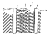
- FIG. 1 is a perspective view showing an appearance of a laminated plate fin heat exchanger (hereinafter simply referred to as a heat exchanger) 1 of the present embodiment.
- the heat exchanger 1 according to the present embodiment includes a supply pipe (inlet header) 4 into which a refrigerant that is a first fluid is supplied, and a plurality of plate fins 2 a each having a rectangular plate shape.
- the plate fin laminated body 2 configured as described above, and a discharge pipe (exit header) 5 that discharges the refrigerant that has flowed through the flow path formed in the plate fin 2a.
- the supply pipe 4 and the discharge pipe 5 are collectively referred to as a supply / discharge pipe.
- end plates 3a and 3b having substantially the same shape in plan view as the rectangular plate fins 2a are disposed at both ends (upper and lower ends) in the stacking direction of the plate fin stack 2 configured by stacking a plurality of plate fins 2a. Is provided.
- the end plates 3a and 3b are formed of a rigid plate material, and are formed by metal processing such as aluminum, aluminum alloy, and stainless steel by grinding.
- the end plates 3a and 3b are disposed so as to sandwich the stacked plate fins 2a from above and below, and are configured to reliably hold the stacked plate fins 2a at a predetermined interval.
- the stacking direction of the plate fin laminate 2 is the vertical direction
- the supply and discharge pipes 4 and 5 are provided on the upper end plate 3 a disposed at the upper end of the plate fin laminate 2.
- a supply pipe 4 and a discharge pipe 5 are provided in the vicinity of both end portions in the longitudinal direction of the plate fin laminate 2 respectively. Accordingly, the refrigerant, which is the first fluid supplied from the supply pipe 4, flows in the horizontal direction through the plurality of flow paths formed inside each plate fin 2 a and is discharged from the discharge pipe 5.
- the refrigerant that is the first fluid flows in parallel in the longitudinal direction through the plurality of flow paths inside each plate fin 2a of the plate fin laminate 2. It is.
- the air that is the second fluid is configured to pass through the gap formed between the stacked plate fins 2 a in the plate fin stacked body 2.
- heat exchange between the first fluid and the second fluid is performed in the plate fin laminate 2.
- the plate fin laminate 2 in the heat exchanger 1 of the present embodiment is configured by laminating plate fins 2a (6, 7) having two kinds of flow path configurations.
- the first plate fins 6 and the second plate fins 7 of the two types of plate fins 2 a are alternately arranged in the plate fin laminate 2.
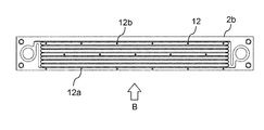
- FIG. 2 is a plan view showing the first plate fin 6.
- the first plate fin 6 includes a header region H formed on both sides in the longitudinal direction and a flow channel region P formed between the header regions H on both sides.
- header openings 8 through which the refrigerant from the supply pipe 4 or the refrigerant to the discharge pipe 5 flows are formed.
- header flow paths 10 through which the refrigerant from the header openings 8 or the refrigerant to the header openings 8 flow are respectively formed, and the respective headers formed on both sides of the first plate fin 6.
- the flow path 10 has a symmetrical shape.
- the header flow paths 10 disposed on both sides of the first plate fin 6 are point-symmetric with the center of the first plate fin 6 in plan view as the center of symmetry, as will be described later. Has a shape.
- first plate fin 6 a plurality of refrigerant flow paths (first fluid flow paths) for flowing the refrigerant from the supply pipe 4 to the discharge pipe 5 are formed in the flow path area P formed between the header areas H on both sides. 11 is formed.
- the plurality of refrigerant flow paths 11 are formed in parallel in the longitudinal direction and communicate with the header flow paths 10 in the header regions H on both sides.
- a header opening 8 which is a circular through hole, is formed in the approximate center of each of the header regions H on both sides, and a header channel 10 through which a coolant flows is formed around the header opening 8.
- the header flow path 10 is short from the outer peripheral flow path 10a formed so as to bulge up and down on the outer periphery of the header opening 8, and from the flow path region P side (the center side of the first plate fin 6) in the outer peripheral flow path 10a.
- One bypass channel 10b extending in the hand direction and a multi-branch channel 10c connecting the bypass channel 10b to each refrigerant channel 11 in the channel region P are included.
- the header flow paths 10 provided on both sides of the first plate fin 6 have a symmetrical shape.
- bypass flow path 10b of the left header flow path 10 shown in FIG. 2 extends from the flow path region P side of the outer peripheral flow path 10a to one side in the short direction (upward direction in FIG. 2).
- the bypass flow path 10b of the header flow path 10 extends from the flow path region P side of the outer peripheral flow path 10a to the other side in the short side direction (downward in FIG. 2). That is, the header flow paths 10 provided on both sides of the first plate fin 6 have a point-symmetric shape with the center of the first plate fin 6 in the plan view as the center of symmetry.
- the bypass channel 10 b extending in the short direction of the first plate fin 6 branches and communicates with a plurality of refrigerant channels 11 arranged in parallel in the channel region P. It is connected to the road 10c.
- the position where the bypass channel 10 b is connected to the multi-branch channel 10 c is on the channel extension of the endmost refrigerant channel 11 in the short direction of the first plate fin 6. Therefore, as shown in FIG. 2, the header channel 10 is formed in a U shape by a bypass channel 10b and a multi-branch channel 10c extending from the outer peripheral channel 10a. It is formed so as to be folded by the path 10c.
- the bypass channel 10 b and the multi-branch channel 10 c on both sides of the first plate fin 6 have a point-symmetric shape with the center of the first plate fin 6 in the plan view as the center of symmetry.
- the refrigerant that has passed through the bypass flow path 10 b is sequentially arranged in parallel from the endmost refrigerant flow path 11 in the short direction of the first plate fin 6. The refrigerant is sent to
- a plurality of protrusions 12 are formed in the flow path region P so as to be adjacent to the refrigerant flow path 11 with a predetermined interval. ing.
- These protrusions 12 (12a, 12b) have two types of shapes (particularly, different protrusion lengths).
- the first dowel 12a is a flow channel region support portion, and protrudes from the edge portion (the lower edge portion in FIG. 2) of the flow channel region P.
- the first dowel 12a is configured to abut the edge of the flow path region P in the plate fin 2a adjacent in the stacking direction in the plate fin stack 2. In this way, the first dowel 12a abuts against the edge of the flow path region P of the adjacent plate fin 2a, so that the distance between the stacked plate fins 2a is reliably defined to a predetermined length.
- the second dowel 12b is a flow path support part, and is disposed with a predetermined interval between the flow paths of the refrigerant flow paths 11 arranged in parallel in the flow path region P.
- the second dowels 12b are arranged along with the first dowels 12a along the flow direction of the second fluid (air).
- the second dowel 12b is disposed so as to face the refrigerant flow path 11 in the plate fin 2a adjacent in the stacking direction in the plate fin laminate 2, and the tube wall (outer wall) of the refrigerant flow path 11 in the adjacent plate fin 2a. ).
- the gap between the adjacent plate fin 2a and the refrigerant flow path 11 is surely defined to a predetermined length. Is done.
- the first dowels 12a and the second dowels 12b may be arranged in a staggered arrangement with respect to the flow direction of the second fluid (air: B in FIG. 2) that flows between the stacks of the plate fin laminate 2. It is sufficient that at least the second dowels 12b are arranged in a staggered arrangement with respect to the flow direction of the second fluid.
- the positioning hole 13 is a positioning hole for stacking a plurality of plate fins 2a (6, 7), and a positioning pin is attached to the positioning hole 13 so that the stacking position with other plate fins 2a is held with high accuracy.
- the positioning pin may be fixed in the state inserted in the positioning hole, and it is good also as a structure which improves the rigidity as a heat exchanger. On the other hand, the positioning pin may be finally pulled out from the heat exchanger in order to reduce the weight of the heat exchanger.
- a positioning outer peripheral portion 13 a bulging up and down is formed on the outer peripheral portion of the positioning hole 13.
- the positioning outer peripheral portion 13a forms a space different from the flow path through which the refrigerant flows.
- the positioning outer peripheral portion 13a abuts between the plate fins 2a (6, 7) adjacent in the stacking direction, and maintains a predetermined interval between the plate fins 2a adjacent in the stacking direction. It becomes a header area
- the positioning outer peripheral portion 13a formed around the header flow path 10 (10a, 10b, 10c) and the positioning hole 13 formed in the header region H has a predetermined height on the upper surface and the lower surface of the first plate fin 6. It is formed so as to protrude.
- the protrusion surfaces (upper end surface and lower end surface) of the header channel 10 (10a, 10b, 10c) and the positioning outer peripheral portion 13a are formed as flat surfaces. Therefore, the vertical cross-sectional shape orthogonal to the flow direction in the header flow path 10 (10a, 10b, 10c) has a rectangular shape with flat protruding portions (upper end portion and lower end portion).
- the height of the header flow path 10 and the positioning outer peripheral portion 13a is half the gap (distance) between the plate fins 2a adjacent in the stacking direction in the plate fin stack 2 (1/2 pitch). ).
- the tube wall (outer wall) of the header channel 10 and the positioning outer peripheral portion 13a are aligned with the tube wall (outer wall) of the opposing header channel 10 and the positioning outer periphery.
- Each abuts against the portion 13a. Since the outer wall of the header channel 10 that abuts is a flat surface, it becomes a surface that can be securely fixed by brazing, for example. Therefore, the header region H of each plate fin 2a in the plate fin laminate 2 is in a state of being laminated with a certain predetermined interval reliably.
- FIG. 3 is an exploded view showing a part of the configuration of the first plate fin 6 in the plate fin laminate 2 in an enlarged manner.
- the 1st plate fin 6 is formed with metal plates, such as aluminum, aluminum alloy, and stainless steel.
- the second plate fins 7 that are alternately laminated with the first plate fins 6 are also formed of the same material as the first plate fins 6.
- the first plate fin 6 includes a first plate member 6 a obtained by pressing a plate material in which at least one brazing material layer is formed on a core material, and a second plate material obtained by pressing a plate material having the same configuration. It is formed by bonding with the plate-like member 6b.
- the (first dowel 12a and second dowel 12b) 12 are pressed into the shape in which each is formed.
- the outer peripheral flow path 10a formed in the header region H, the header flow path 10 composed of the bypass flow path 10b and the multi-branch flow path 10c, and the positioning outer peripheral portion 13a formed around the positioning hole 13 Are formed so as to protrude from the upper surface and the lower surface of the first plate fin 6 and each has the same height that is half the distance (1/2 pitch) between the adjacent plate fins 2a in the stacking direction. Yes. Further, the outer peripheral flow path 10a, the bypass flow path 10b, and the multi-branch flow path 10c in the header flow path 10 are formed wider than the refrigerant flow path 11 arranged in parallel in the flow path region P, and the flow direction
- the vertical cross-sectional shape orthogonal to the above has a rectangular shape.
- the hydraulic diameter is desirably 1 mm or less.
- coolant flow path 11 demonstrates circular shape, in this indication, it is not limited to circular shape.
- the circular shape includes a complex curve shape formed by a circle, an ellipse, and a closed curve.
- the cross-sectional shape orthogonal to the direction in which the refrigerant flows includes a circular shape in addition to a circular shape, and protrudes only on one side in the stacking direction. Including a configuration formed so as to protrude from both sides in the stacking direction.
- FIG. 4 which shows various cross-sectional shapes of a refrigerant flow path
- the refrigerant flow path 11 is formed of two plate-like members, it is shown in a separated state.
- the plate-like member is abutted to form a coolant channel 11 having a predetermined cross-sectional shape.
- FIG. 5 is a plan view showing the vicinity of the header region H of the first plate fin 6 in the plate fin laminate 2.
- FIG. 6 is a perspective view showing a cross section of the plate fin laminate 2 shown in FIG. 5 taken along line VI-VI. As shown in the plate fin laminate 2 in FIG. 6, the plate fin laminate 2 is configured by alternately laminating first plate fins 6 and second plate fins 7.
- FIG. 6 shows a state in which four plate fins (6, 7) are laminated, but this is a part, and in the plate fin laminate 2, a large number of plate fins (6, 7) are shown. Are stacked alternately.
- the plate fin laminated body 2 is configured such that the outer wall (flat surface) of the header channel 10 in the header region H of each of the first plate fin 6 and the second plate fin 7 is adjacent to the plate fin (6, 7) in the stacking direction. It contacts the outer wall (flat surface) of the header channel 10 in the stacking direction.
- FIG. 6 it is shown that the flat surface of the outer wall of the outer peripheral flow path 10a is in contact with the flat surface of the outer wall of the outer peripheral flow path 10a of the plate fins (6, 7) adjacent in the stacking direction.
- the refrigerant flowing through the header channel 10 is applied with high pressure in the header channel 10, but the header of the plate fins (6, 7) adjacent to the pipe wall (outer wall) of the header channel 10.
- FIG. 7 is a cross-sectional view showing a part of a header region H obtained by processing plate materials having different thicknesses by press molding.
- the pipe wall portion of the header flow path 10 in the header region H is configured with a thick wall portion that is thicker than other portions, thereby ensuring even higher pressure refrigerant. It becomes the structure of the heat exchanger which can respond.
- only the tube wall of the refrigerant flow path 11 in the flow path region P may be formed of a thick part thicker than other parts as shown in FIG. By comprising in this way, it becomes a structure which can respond to the refrigerant
- the 1st plate fin 6 and the 2nd plate fin 7 are laminated
- the second plate fin 7 has substantially the same configuration and shape as the first plate fin 6, but the refrigerant flow path 11 and the protrusion 12 (first dowel 12a, second dowel 12b in the flow path region P). ) Are different from the first plate fin 6.
- FIG. 8 is a diagram showing that the plate fin laminate 2 is configured by laminating the first plate fins 6 and the second plate fins 7.
- the refrigerant flow path 11 in the flow path region P is at a position facing the second dowel 12 b of the first plate fin 6. That is, the refrigerant flow path 11 in the flow path area P of the second plate fin 7 is disposed so as to face the position between the refrigerant flow paths 11 in the flow path area P of the first plate fin 6.
- the second dowel 12b which is the flow path support portion, securely contacts the pipe wall (outer wall) of the refrigerant flow path 11 facing the second dowel 12b. It is the structure which touches.
- the refrigerant flow paths in the first plate fins 6 and the second plate fins 7 that are alternately stacked in a cross section orthogonal to the direction in which the first fluid A flows in the flow path region P. 11 is configured in a staggered arrangement. See FIG. 18 to be described later for a specific configuration of the staggered arrangement.
- the first dowel 12 a that is the flow channel region support portion formed at the edge of the flow channel region P of the second plate fin 7 contacts the edge of the flow channel region P of the adjacent first plate fin 6. It is the composition fixed. Therefore, the protruding height of the first dowel 12a that is the flow channel region support portion is higher than the protruding height of the second dowel 12b that is the flow channel support portion by the height of the refrigerant flow channel 11.
- FIG. 9 is a perspective view showing a cross section of the plate fin laminate 2 shown in FIG. 8 cut along line IX-IX.
- the plate fin laminate 2 shown in FIG. 9 only four sheets of the first plate fin 6, the second plate fin 7, the first plate fin 6, and the second plate fin 7 are laminated in order from the top. Yes.
- the first dowel 12 a of the flow path region P in the first plate fin 6 is in contact with the edge of the flow path region P in the opposing second plate fin 7. Further, the first dowels 12 a in the flow path region P in the second plate fin 7 are in contact with the edge of the flow path region P in the first plate fin 6 facing each other.
- the second dowels 12b of the flow path region P in the first plate fin 6 are in contact with the pipe wall (outer wall) of the refrigerant flow path 11 in the flow path region P of the second plate fin 7 facing each other. Further, the second dowels 12 b in the flow path region P in the second plate fin 7 are in contact with the pipe wall (outer wall) of the refrigerant flow channel 11 in the flow path region P in the first plate fin 6 that faces the second plate fin 7.
- the laminated plate fins 2a (6, 7) in the plate fin laminate 2 are described as being fixed by brazing, but the present disclosure is not limited to this configuration.
- Other heat-resistant fixing methods such as a mechanical connection method and a fixing method using a chemical bonding member may be used.
- the edge of the flow path region P of the fin plate (6, 7) facing the first dowel 12a of the flow path region P is reliably supported, A predetermined gap is secured between the layers.
- the first dowels 12 a in the flow path region P serve as flow path region support portions in the plate fin laminate 2.
- the second dowel 12b of the flow path region P is in contact with the pipe wall (outer wall) of the refrigerant flow path 11 of the opposing fin plate (6, 7). A predetermined interval is maintained between the stacks of the plates (6, 7) and the refrigerant flow path 11.
- the second dowel 12 b in the flow channel region P serves as a flow channel support portion in the plate fin laminate 2.
- the first dowel 12a of the flow channel region P is described as contacting the edge of the flow channel region P of the opposing fin plate (6, 7), but other configurations can be used. It is.
- the first dowel 12a which is the flow channel region support portion formed at the edge of the flow channel region P, is used as the flow channel region convex portion, and the edge of the flow channel region P of the opposing fin plate (6, 7).
- the channel region recess may be formed in the channel region, and the channel region projection and the channel region recess may be fitted.
- FIG. 10 is a perspective view showing a state where the positioning pins 9 are attached to the plate fin laminate 2.
- FIG. 11 is an enlarged cross-sectional view of the plate fin laminate 2 to which the positioning pins 9 are attached.
- FIG. 11 is a cross-sectional view taken along the plane indicated by reference numeral XI-XI in FIG.
- the positioning pin 9 is inserted into the positioning hole 13 which is a through hole formed in the header region H of each plate fin 2a (6, 7) and brazed.
- the plate fin laminate 2 has a structure in which the mechanical structure is strengthened and the pressure resistance against the refrigerant is remarkably strengthened.
- an aluminum metal rod is used as the positioning pin 9.
- the first dowel 12 a that is the flow channel region support portion and the second dowel 12 b that is the flow channel support portion formed in the flow channel region P are the second fluid B.
- the plurality of protrusions are arranged side by side between the stacked layers, the flow resistance against the second fluid (air) B flowing between the stacked layers in the plate fin stacked body 2 can be reduced.
- the plate fin laminate 2 of the present embodiment it is possible to reduce the sound generated when the second fluid flows between the laminates.
- FIG. 12 is a plan view of the plate fin 2b showing a configuration in which a plurality of protrusions 12 (12a, 12b) are arranged in a staggered arrangement between the laminations in the plate fin laminate 2.
- FIG. 12a Also in this configuration, the first dowel 12a that is the flow channel region support portion abuts on the edge of the opposed flow channel region P, and the second dowel 12b that is the flow channel support portion is in contact with the opposite flow channel region P.
- the refrigerant channel 11 is configured to come into contact with the tube wall (outer wall).
- a plurality of protrusions 12 between the stacks may be formed more on the leeward side than on the windward side, thereby generating a turbulent flow in the second fluid B passing between the stacks to improve the heat exchange efficiency.
- at least the number of the first dowels 12a in the protrusions 12 may be configured so that the leeward side has more protrusions 12 than the windward side in the flow direction of the second fluid B (air).
- FIG. 13 is a plan view of the plate fin 2c showing a configuration in which more leeward projections 12 are provided than the leeward projections 12 in the flow direction of the air that is the second fluid B.
- the first dowel 12a that is the flow channel region support portion abuts on the edge of the opposed flow channel region P
- the second dowel 12b that is the flow channel support portion is in contact with the opposite flow channel region P. It contacts the pipe wall (outer wall) of the refrigerant flow path.
- the supply pipe 4 and the discharge pipe 5 are connected in the vicinity of both end portions in the longitudinal direction, and the header regions H are formed on both sides of each plate fin 2a.
- two header openings 8 are provided (see FIG. 2).
- FIG. 14 is a view showing a modification of the plate fin laminate, and is a plan view showing plate fins 2d constituting the plate fin laminate.
- the header region H is formed only on one end side (left side in FIG. 14) of the plate fin 2 d, and the other region is the flow channel region P. That is, in the plate fin laminated body of this modification, the supply pipe and the discharge pipe are connected to a region in the vicinity of one end in the longitudinal direction.
- both a header opening 8a on the supply side and a header opening 8b on the discharge side are formed in the header region H shown on the left side.
- the opening shape of the header opening 8a on the supply side has a larger diameter than the opening shape of the header opening 8b on the discharge side.
- the heat exchanger is used as a condenser.
- the volume of the refrigerant after the heat exchange is reduced.
- the refrigerant from the header opening 8a on the supply side flows through the plurality of refrigerant flow paths 11a arranged in parallel in the flow path region P, and is folded back in the vicinity of the end of the plate fin 2d (in the vicinity of the right end in FIG. 14). It is a configuration.
- a refrigerant flow path 11a into which the refrigerant flows from the header opening 8a on the supply side and a refrigerant flow path 11b in which the refrigerant flows into the header opening 8b on the discharge side after being folded near the end are formed.
- an entrance and exit becomes reverse to the above.
- the number of the parallel refrigerant flow paths 11b in which the refrigerant flows into the discharge-side header opening 8b is equal to the parallel refrigerant flow paths in which the refrigerant from the supply-side header opening 8a flows.
- the number is set to be less than the number 11a. This is the same reason that the diameters of the header openings 8a and 8b are different, because the volume of the refrigerant after heat exchange is reduced.
- the region where the refrigerant flow path 11a into which the refrigerant from the header opening 8a on the supply side flows and the refrigerant flow path 11b flowing to the header opening 8b on the discharge side are formed.
- a plurality of openings 16 are formed between the formed regions for the purpose of reducing heat conduction between the refrigerants in the plate fin (heat insulation).
- FIG. 15 is a perspective view showing the upper end plate 3a provided at the upper end of the plate fin laminate 2 in the stacking direction
- FIG. 16 shows the lower end plate 3b provided at the lower end of the plate fin stack 2 in the stacking direction. It is a perspective view shown.
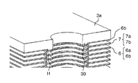
- FIG. 17 is an enlarged perspective view showing a joined state between the header region H and the upper end plate 3 a in the plate fin laminate 2.
- each of the first plate fin 6 and the second plate fin 7 constituting the plate fin laminate 2 includes two plate-like members (6a and 6b, 7a and 7b). Are formed. That is, the first plate fin 6 is formed by laminating the pressed first plate member 6a and the second plate member 6b, and the second plate fin 7 is formed by pressing the first plate. The plate-like member 7a and the second plate-like member 7b are bonded together.
- the first plate fins 6 and the second plate fins 7 are alternately laminated, and the uppermost end portion of the plate fin laminate 2 is one side of the first plate fin 6. Only the second plate-like member 6b is disposed (see FIG. 17). Therefore, the uppermost end surface of the plate fin laminate 2 has a recess that is a narrow groove for forming a flow path, and most of the uppermost end surface is a flat surface. For this reason, the flat surface in the uppermost end surface of the plate fin laminated body 2 becomes a bonding surface (brazing surface) that is a contact surface with the lower surface of the upper end plate 3a, and the bonding area increases.
- the end plate convex part 30 is formed in the surface facing the plate fin laminated body 2 in the upper end plate 3a arrange
- This end plate convex part 30 has a shape corresponding to the recess for flow path formation in the opposing 2nd plate-shaped member 6b. For this reason, when the upper end plate 3a is disposed on the uppermost surface of the plate fin laminate 2, the end plate protrusion 30 of the upper end plate 3a becomes a recess for forming a flow path in the second plate member 6b. Fit.
- the end plate convex portion 30 formed on the upper end plate 3a may be formed only in the concave portion for forming a wide flow path in the header region H. This is because the recesses (grooves) for forming the flow channel in the flow channel region P are narrow and a sufficient contact surface is secured.
- the second plate-like member 6b of the first plate fin 6 is disposed as the uppermost surface of the plate fin laminate 2 will be described.
- the uppermost surface of the laminated body 2 should just be comprised by any one side in the 1st plate fin 6 or the 2nd plate fin 7 according to a lamination order.
- FIG. 18 is an enlarged perspective view showing a joined state between the lowermost end surface of the plate fin laminate 2 and the lower end plate 3b.
- the first plate member 7 a that is one side of the second plate fin 7 is disposed at the lowermost end portion of the plate fin laminate 2. Therefore, the lowermost end surface of the plate fin laminate 2 has a recess for forming a flow path, but most of the lowermost end surface is a flat surface. Therefore, a sufficient bonding area is ensured between the lowermost end surface of the plate fin laminate 2 and the lower end plate 3b.
- [Modification of plate fin laminate and end plate] 19 to 25 are diagrams showing various modifications of the plate fin laminate and the end plate.
- FIG. 19 is an enlarged perspective view showing a joined state between the lowermost end surface of the plate fin laminate 2 and the lower end plate 31b.
- a first plate member 7 a that is one side of the second plate fin 7 is disposed at the lowermost end of the plate fin laminate 2.
- the lowermost end surface of the plate fin laminate 2 has a downwardly facing concave surface for the first fluid channel recess 11a that constitutes the upper half of the refrigerant channel 11 that is the first fluid channel in the first plate member 7a. It is comprised by.
- the surface having the concave surface (groove) of the concave portion 11a for the first fluid flow path faces downward and is in contact with the upper surface of the lower end plate 31b.
- FIG. 20 is a plan view showing the upper surface of the lower end plate 31b.
- a flow path region P and a header region H having the same configuration as the first plate-like member 7a facing the lower end plate 31b are disposed on the upper surface of the lower end plate 31b. ing. That is, the header region H is formed on both sides in the longitudinal direction of the lower end plate 31b, and the flow channel region P is formed in the central portion sandwiched between the header regions H.
- a header channel recess 32 is formed in the header region H on the upper surface of the lower end plate 31b, and a plurality of linear coolant channel recesses (grooves) 33 are formed in the channel region P. It is formed in parallel. Note that the header flow path recess 32 in the header region H of the lower end plate 31b is formed of a bottomed recess having substantially the same circular shape as the header opening 8 of the plate fins (6, 7). The header channel recess 32 blocks the refrigerant in the header opening 8 communicating with the supply / discharge pipe.
- the coolant channel recess (groove) 33 of the channel region P formed in the lower end plate 31 b is formed in the first plate member 7 a that is one side of the opposing second plate fin 7. It has the same shape at the same position as the coolant channel recess 11a. Therefore, in the lower end plate 31b, the first plate member 7a facing the lower end plate 31b forms a header flow path serving as a refrigerant pool in the header area H, and a plate fin stack in the flow path area P. The same coolant channel as the coolant channel 11 in the body 2 is formed. As a result, in the heat exchanger configured as described above, a refrigerant flow path is formed by the lower end plate 31b and the first plate member 7a at the lowermost end, and the heat exchange efficiency can be further increased. Become.
- the configurations of the lowermost end surface of the plate fin laminate 2 and the lower end plate 31b shown in FIGS. 19 and 20 are similarly configured on the uppermost end surface of the plate fin laminate 2 and the lower surface of the upper end plate.
- a refrigerant flow path can be formed between the uppermost end surface of the plate fin laminate 2 and the lower surface of the upper end plate.
- FIG. 21 and FIGS. 22A and 22B are views showing a plate fin laminate 21 and a lower end plate 34b of still another configuration.
- FIG. 21 is an enlarged perspective view showing a joined state between the lowermost end of the plate fin laminate 21 and the lower end plate 34b.
- FIG. 22A is a plan view showing the upper surface of the lower end plate 34b.
- FIG. 22B is a side view of the lower end plate 34b.
- the second plate fin 7 is disposed at the lowermost end of the plate fin stack 21.
- the plate fin laminate 21 includes first plate fins 6 and second plate fins 7 formed by joining two plate-like members (6a and 6b, 7a and 7b) alternately. It is configured by stacking. Therefore, in the present modification, either the first plate fin 6 or the second plate fin 7 is arranged at the lowermost end of the plate fin laminate 21 according to the stacking order.
- a plurality of protrusions (35, 36) are formed on the upper surface of the lower end plate 34b, and the second plate fin 7 at the lowermost end of the plate fin laminate 21 is provided, for example. It is configured to support.
- the flow path support convex portion 35 that supports the refrigerant flow path 11 of the second plate fin 7 and the flow of the second plate fin 7 It is divided into a flow path region supporting convex portion 36 that supports the road region P.
- the flow path supporting convex portion 35 and the flow path region supporting convex portion 36 have two types of shapes (particularly, the protruding lengths are different).
- the convex part 36 for supporting the flow path region of the lower end plate 34 b is configured to come into contact with the edge of the flow path region P in the second plate fin 7. As described above, the flow path region supporting convex portion 36 comes into contact with the edge of the flow path region P of the second plate fin 7, so that the distance between the lower end plate 34 b and the second plate fin 7 is predetermined. The length is definitely specified.
- the flow path support convex portion 35 is a flow path support portion, and is disposed at the position of the refrigerant flow path 11 arranged in parallel in the flow path region P of the second plate fin 7 facing each other.
- the flow path support convex portions 35 are arranged along with the flow path region support convex portions 36 along the flow direction of the second fluid (air).
- the flow path support convex portion 35 is disposed so as to face the refrigerant flow path 11, and abuts on the tube wall (outer wall) of the refrigerant flow path 11 of the second plate fin 7.
- the flow path supporting convex portion 35 contacts the tube wall (outer wall) of the refrigerant flow path 11 of the second plate fin 7, the upper surface of the lower end plate 34b and the second plate fin 7 at the lowermost end Is reliably defined to a predetermined length.
- the plurality of protrusions (35, 36) formed on the upper surface of the lower end plate 34b are arranged in a staggered arrangement with respect to the flow direction of the second fluid (air: B) flowing through the plate fin laminate 21. Also good. Further, the plurality of protrusions (35, 36) may be formed more on the leeward side than on the leeward side.
- the configurations of the lowermost end surface and the lower end plate 34b of the plate fin laminate 21 shown in FIGS. 21 and 22A and 22B are the same in the uppermost end surface of the plate fin laminate 21 and the lower surface of the upper end plate. It becomes possible to do.
- FIG. 23 and FIGS. 24A and B are views showing a lower end plate 37b having still another configuration.
- FIG. 23 is an enlarged perspective view showing a joined state between the lowermost end of the plate fin laminate 21 and the lower end plate 37b.
- FIG. 24A is a plan view showing the upper surface of the lower end plate 37b.
- FIG. 24B is a side view of the lower end plate 37b.
- the plate fin laminate 21 is the same as the configuration of the plate fin laminate 21 shown in FIG. That is, in this modified example, the plate fin laminate 21 is configured by alternately laminating the first plate fins 6 and the second plate fins 7, and the first fins 21 are arranged at the lowest end of the first plate fin laminate 21. Either the plate fin 6 or the second plate fin 7 is arranged according to the stacking order.
- a plurality of protrusions (38, 39) extending in the longitudinal direction are formed on the upper surface of the lower end plate 37b, and are located at the lowermost end of the plate fin laminate 21.
- the second plate fin 7 is configured to be supported.
- a flow path supporting convex portion 38 for supporting the refrigerant flow path 11 of the second plate fin 7 is divided into flow channel region supporting convex portions 39 that support the flow channel region P.
- the flow path support convex portion 38 and the flow path region support convex portion 39 have two types of shapes (particularly, different protrusion lengths).
- the flow path region supporting convex portion 39 of the lower end plate 37 b comes into contact with the edge portion of the flow path region P in the second plate fin 7. As described above, the flow path region supporting convex portion 39 comes into contact with the edge of the flow path region P of the second plate fin 7, so that the distance between the lower end plate 37 b and the second plate fin 7 is predetermined. The length is definitely specified.
- the flow path support convex portion 38 is a flow path support portion, and is disposed at the position of the refrigerant flow path 11 arranged in parallel in the flow path region P of the second plate fin 7 facing each other.
- the flow path support convex portion 38 is disposed so as to face the refrigerant flow path 11, and reliably contacts the tube wall (outer wall) of the refrigerant flow path 11 of the second plate fin 7.
- the flow path supporting convex portion 38 abuts on the tube wall (outer wall) of the refrigerant flow path 11 of the second plate fin 7, the upper surface of the lower end plate 37b and the second plate fin 7 at the lowermost end Is reliably defined to a predetermined length.
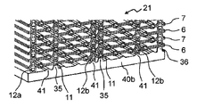
- FIG. 25 is a view showing a lower end plate 40b having still another configuration.
- FIG. 25 is an enlarged perspective view showing a joined state between the lowermost end of the plate fin laminate 21 and the lower end plate 40b.
- the plate fin laminate 21 is the same as the configuration of the plate fin laminate 21 shown in FIG.
- a dowel that is joined to the upper surface of the lower end plate 40b in contact with and joined to the second dowel 12b that is a flow path support portion of the second plate fin 7 disposed at the lowermost end of the plate fin laminate 21, for example.
- a support convex portion 41 is formed.
- the dowel support convex portion 41 is a ridge-shaped protrusion that extends in the longitudinal direction, and extends between the refrigerant flow paths 11 in the opposing second plate fins 7. Further, the dowel support convex portion 41 has a height that surely contacts the second dowel 12 b provided between the refrigerant flow paths 11 in the second plate fin 7.
- the first dowels 12a formed at the edges of the plate fins (6, 7) disposed at the lowermost end of the plate fin laminate 21 have a height that makes contact with the upper surface of the lower end plate 40b. Yes.
- the configuration of the lowermost end surface of the plate fin laminate 21 and the lower end plate 40b shown in FIG. 25 can be similarly configured on the uppermost end surface of the plate fin laminate 21 and the lower surface of the upper end plate. Become.
- FIG. 26 shows a modification in which a pair of side plates 17 and 18 are provided in the heat exchanger of the present disclosure so as to sandwich the end plates 3a and 3b provided on the upper and lower ends of the plate fin laminate 2 from both side surfaces. It is a perspective view shown.
- the modification shown in FIG. 26 is configured such that the side surface on the side of one header region H to which the feed pipe 4 is connected in the plate fin laminate 2 is sandwiched from above and below by the first side plate 17. Further, the other side of the header region H to which the discharge pipe 5 is connected in the plate fin laminate 2 is configured to be sandwiched from above and below by the second side plate 18.
- the first side plate 17 is formed with an upper opening 17 a through which the feed pipe 4 passes and a side opening 17 b so that air as the second fluid B flows into the header region of the plate fin laminate 2.
- the second side plate 18 is formed with an upper opening 18 a through which the discharge pipe 5 passes and a side opening 18 b so that air as the second fluid B flows into the header region H of the plate fin laminate 2.
- the pair of side plates 17 and 18 are provided so as to sandwich the upper and lower portions of the header region H from both sides of the plate fin laminate 2. Even if the thickness of 3b is reduced and the structure is simple, the pipe wall of the header flow path 10 in the header region H of the plate fin 2a constituting the plate fin laminate 2 can be reliably pressed from above and below with a predetermined pressure. It becomes composition.
- the plate fin laminated body 2 configured in this way can flow a refrigerant having a desired high pressure to the plate fin laminated body 2 and can perform heat exchange with high efficiency.
- FIG. 26 the configuration example for the plate fin laminate 2 shown in FIG. 1 has been described.
- the configuration of the modification example described with reference to FIGS. It is possible to provide a structure in which the plate fin laminate is sandwiched between the upper and lower sides. Even in the configuration of such a modified example, the plate fin laminate can be reliably pressed from above and below at a predetermined pressure, and a refrigerant with a desired high pressure can be flowed through the plate fin laminate, so that efficient heat exchange can be achieved.
- the heat exchanger As described above, in the configuration of the heat exchanger according to the present disclosure, weight reduction, downsizing, and high heat exchange efficiency can be achieved, and high-pressure refrigerant flows through the plate fins in the plate fin stack. Even if it is a structure, it becomes a heat exchanger with high reliability and high heat exchange efficiency.
- the present disclosure is a device that has been reduced in weight and size, and can perform heat exchange with high reliability and efficiency, so that it becomes a heat exchanger with high market value.
Abstract
La présente invention concerne un échangeur de chaleur comprenant : un corps empilé d'ailettes en plaques obtenu par empilement d'ailettes en plaques comportant des circuits d'écoulement à travers lesquels un premier fluide s'écoule ; et des tuyaux d'alimentation et d'évacuation à travers lesquels passe le premier fluide s'écoulant dans les circuits d'écoulement de chaque ailette en plaques du corps empilé d'ailettes en plaques. Un second fluide passe entre les couches du corps empilé d'ailettes en plaques, et le premier fluide et le second fluide échangent de la chaleur. Les ailettes en plaques comprennent chacune : une région de circuit d'écoulement munie de plusieurs premiers circuits linéaires d'écoulement de fluide de sorte que le premier fluide s'écoule en parallèle ; et des régions de collecteur munies de circuits d'écoulement de collecteur permettant à chaque premier circuit d'écoulement de fluide dans la région de circuit d'écoulement d'être en communication avec les tuyaux d'alimentation et d'évacuation. Les parois externes des circuits d'écoulement de collecteur sont mises en contact avec les parois externes des circuits d'écoulement de collecteur des ailettes en plaques adjacentes dans le corps empilé d'ailettes en plaques dans la direction d'empilement.
Priority Applications (2)
| Application Number | Priority Date | Filing Date | Title |
|---|---|---|---|
| CN201780019132.0A CN108885075B (zh) | 2016-03-28 | 2017-02-27 | 热交换器 |
| DE112017001572.3T DE112017001572T5 (de) | 2016-03-28 | 2017-02-27 | Wärmetauscher |
Applications Claiming Priority (2)
| Application Number | Priority Date | Filing Date | Title |
|---|---|---|---|
| JP2016-063296 | 2016-03-28 | ||
| JP2016063296A JP6504367B2 (ja) | 2016-03-28 | 2016-03-28 | 熱交換器 |
Publications (1)
| Publication Number | Publication Date |
|---|---|
| WO2017169410A1 true WO2017169410A1 (fr) | 2017-10-05 |
Family
ID=59964209
Family Applications (1)
| Application Number | Title | Priority Date | Filing Date |
|---|---|---|---|
| PCT/JP2017/007273 WO2017169410A1 (fr) | 2016-03-28 | 2017-02-27 | Échangeur de chaleur |
Country Status (4)
| Country | Link |
|---|---|
| JP (1) | JP6504367B2 (fr) |
| CN (1) | CN108885075B (fr) |
| DE (1) | DE112017001572T5 (fr) |
| WO (1) | WO2017169410A1 (fr) |
Cited By (3)
| Publication number | Priority date | Publication date | Assignee | Title |
|---|---|---|---|---|
| CN109028660A (zh) * | 2018-05-09 | 2018-12-18 | 河南科隆集团有限公司 | 一种翅片式蒸发器及其制作方法 |
| CN110285603A (zh) * | 2018-03-19 | 2019-09-27 | 松下知识产权经营株式会社 | 热交换器和使用其的制冷系统 |
| CN112066598A (zh) * | 2019-06-11 | 2020-12-11 | 广东美的制冷设备有限公司 | 换热器及空调设备 |
Families Citing this family (10)
| Publication number | Priority date | Publication date | Assignee | Title |
|---|---|---|---|---|
| JP6528283B2 (ja) * | 2016-03-28 | 2019-06-12 | パナソニックIpマネジメント株式会社 | 熱交換器 |
| JP2019152348A (ja) * | 2018-03-01 | 2019-09-12 | パナソニックIpマネジメント株式会社 | 熱交換ユニットおよびそれを用いた空気調和機 |
| JP6887074B2 (ja) * | 2018-03-05 | 2021-06-16 | パナソニックIpマネジメント株式会社 | 熱交換器 |
| JP6865354B2 (ja) * | 2018-04-09 | 2021-04-28 | パナソニックIpマネジメント株式会社 | プレートフィン積層型熱交換器およびそれを用いた冷凍システム |
| JP6934609B2 (ja) * | 2019-04-17 | 2021-09-15 | パナソニックIpマネジメント株式会社 | 熱交換器およびそれを用いた冷凍システム |
| JP2020176768A (ja) * | 2019-04-18 | 2020-10-29 | パナソニックIpマネジメント株式会社 | 熱交換器およびそれを用いた冷凍システム |
| JP7365635B2 (ja) * | 2019-10-17 | 2023-10-20 | パナソニックIpマネジメント株式会社 | 熱交換器 |
| JP7365634B2 (ja) * | 2019-10-17 | 2023-10-20 | パナソニックIpマネジメント株式会社 | 熱交換器 |
| KR102393899B1 (ko) * | 2020-07-09 | 2022-05-02 | 두산에너빌리티 주식회사 | 인쇄기판형 열교환기를 포함하는 열교환 장치 |
| CN113294941A (zh) * | 2021-07-05 | 2021-08-24 | 珠海市华晶农谷微冻瞬冷科学研究院 | 一种制冷蒸发系统的专用板式蒸发器及其工作方法 |
Citations (6)
| Publication number | Priority date | Publication date | Assignee | Title |
|---|---|---|---|---|
| JPH021U (fr) * | 1988-06-06 | 1990-01-05 | ||
| JP2001208487A (ja) * | 2000-01-28 | 2001-08-03 | Mitsubishi Heavy Ind Ltd | 燃焼触媒一体蒸発装置 |
| JP2002130977A (ja) * | 2000-10-27 | 2002-05-09 | Denso Corp | 熱交換器 |
| JP2007285691A (ja) * | 2006-03-22 | 2007-11-01 | Matsushita Electric Ind Co Ltd | 熱交換器 |
| JP2008116102A (ja) * | 2006-11-02 | 2008-05-22 | Denso Corp | 冷却用熱交換器 |
| JP2016151392A (ja) * | 2015-02-18 | 2016-08-22 | 有限会社和氣製作所 | 熱交換器 |
Family Cites Families (5)
| Publication number | Priority date | Publication date | Assignee | Title |
|---|---|---|---|---|
| JP4770534B2 (ja) * | 2006-03-22 | 2011-09-14 | パナソニック株式会社 | 熱交換器 |
| JP4231518B2 (ja) * | 2006-10-24 | 2009-03-04 | トヨタ自動車株式会社 | 熱交換装置 |
| CN201954990U (zh) * | 2010-05-13 | 2011-08-31 | 艾普尔换热器(苏州)有限公司 | 一种板式换热器 |
| FR2980837B1 (fr) * | 2011-10-04 | 2015-06-26 | Valeo Systemes Thermiques | Echangeur de chaleur a plaques empilees. |
| JP3192719U (ja) * | 2014-06-18 | 2014-08-28 | 有限会社和氣製作所 | 板状部材および熱交換器 |
-
2016
- 2016-03-28 JP JP2016063296A patent/JP6504367B2/ja active Active
-
2017
- 2017-02-27 DE DE112017001572.3T patent/DE112017001572T5/de active Pending
- 2017-02-27 CN CN201780019132.0A patent/CN108885075B/zh active Active
- 2017-02-27 WO PCT/JP2017/007273 patent/WO2017169410A1/fr active Application Filing
Patent Citations (6)
| Publication number | Priority date | Publication date | Assignee | Title |
|---|---|---|---|---|
| JPH021U (fr) * | 1988-06-06 | 1990-01-05 | ||
| JP2001208487A (ja) * | 2000-01-28 | 2001-08-03 | Mitsubishi Heavy Ind Ltd | 燃焼触媒一体蒸発装置 |
| JP2002130977A (ja) * | 2000-10-27 | 2002-05-09 | Denso Corp | 熱交換器 |
| JP2007285691A (ja) * | 2006-03-22 | 2007-11-01 | Matsushita Electric Ind Co Ltd | 熱交換器 |
| JP2008116102A (ja) * | 2006-11-02 | 2008-05-22 | Denso Corp | 冷却用熱交換器 |
| JP2016151392A (ja) * | 2015-02-18 | 2016-08-22 | 有限会社和氣製作所 | 熱交換器 |
Cited By (4)
| Publication number | Priority date | Publication date | Assignee | Title |
|---|---|---|---|---|
| CN110285603A (zh) * | 2018-03-19 | 2019-09-27 | 松下知识产权经营株式会社 | 热交换器和使用其的制冷系统 |
| CN110285603B (zh) * | 2018-03-19 | 2021-12-24 | 松下知识产权经营株式会社 | 热交换器和使用其的制冷系统 |
| CN109028660A (zh) * | 2018-05-09 | 2018-12-18 | 河南科隆集团有限公司 | 一种翅片式蒸发器及其制作方法 |
| CN112066598A (zh) * | 2019-06-11 | 2020-12-11 | 广东美的制冷设备有限公司 | 换热器及空调设备 |
Also Published As
| Publication number | Publication date |
|---|---|
| DE112017001572T5 (de) | 2018-12-20 |
| CN108885075A (zh) | 2018-11-23 |
| JP2017180856A (ja) | 2017-10-05 |
| CN108885075B (zh) | 2020-08-04 |
| JP6504367B2 (ja) | 2019-04-24 |
Similar Documents
| Publication | Publication Date | Title |
|---|---|---|
| WO2017169410A1 (fr) | Échangeur de chaleur | |
| WO2017169411A1 (fr) | Échangeur de chaleur | |
| JP5892453B2 (ja) | 熱交換器 | |
| WO2015063875A1 (fr) | Collecteur stratifié, échangeur de chaleur, et appareil de climatisation | |
| JP2010114174A (ja) | ヒートシンク用コア構造 | |
| CN113424009B (zh) | 热交换器 | |
| TW200538695A (en) | Heat exchanger and method of producing the same | |
| JP2013002753A (ja) | サーペンタイン型熱交換器 | |
| JP2003307397A (ja) | 熱交換器 | |
| JP3966134B2 (ja) | 熱交換器 | |
| WO2012008348A1 (fr) | Echangeur de chaleur | |
| JP2006317026A (ja) | 積層型熱交換器及びその製造方法 | |
| JP2005326068A (ja) | 熱交換器用プレート及び熱交換器 | |
| KR102634169B1 (ko) | 적층 플레이트형 열교환기 | |
| JP6191414B2 (ja) | 積層型熱交換器 | |
| JP2004293880A (ja) | 積層型熱交換器 | |
| JP2005083623A (ja) | 熱交換ユニット及び積層型熱交換器 | |
| JP2021081158A (ja) | 熱交換器 | |
| JP2005207725A (ja) | 熱交換器 | |
| JP6720890B2 (ja) | 積層型熱交換器 | |
| JP3409350B2 (ja) | 積層型熱交換器 | |
| CN113474613B (zh) | 热交换器 | |
| JP2007017078A (ja) | マイクロチャネル熱交換器の媒体流路形成体 | |
| JP2005308232A (ja) | 熱交換器 | |
| JP2796898B2 (ja) | 熱交換器 |
Legal Events
| Date | Code | Title | Description |
|---|---|---|---|
| 121 | Ep: the epo has been informed by wipo that ep was designated in this application |
Ref document number: 17773955 Country of ref document: EP Kind code of ref document: A1 |
|
| 122 | Ep: pct application non-entry in european phase |
Ref document number: 17773955 Country of ref document: EP Kind code of ref document: A1 |