WO2017169294A1 - 多心ケーブル及び多心ケーブルの製造方法 - Google Patents
多心ケーブル及び多心ケーブルの製造方法 Download PDFInfo
- Publication number
- WO2017169294A1 WO2017169294A1 PCT/JP2017/006280 JP2017006280W WO2017169294A1 WO 2017169294 A1 WO2017169294 A1 WO 2017169294A1 JP 2017006280 W JP2017006280 W JP 2017006280W WO 2017169294 A1 WO2017169294 A1 WO 2017169294A1
- Authority
- WO
- WIPO (PCT)
- Prior art keywords
- conductor
- coaxial cable
- core cable
- removal portion
- peripheral surface
- Prior art date
- Legal status (The legal status is an assumption and is not a legal conclusion. Google has not performed a legal analysis and makes no representation as to the accuracy of the status listed.)
- Ceased
Links
Images








Classifications
-
- H—ELECTRICITY
- H01—ELECTRIC ELEMENTS
- H01B—CABLES; CONDUCTORS; INSULATORS; SELECTION OF MATERIALS FOR THEIR CONDUCTIVE, INSULATING OR DIELECTRIC PROPERTIES
- H01B11/00—Communication cables or conductors
- H01B11/18—Coaxial cables; Analogous cables having more than one inner conductor within a common outer conductor
- H01B11/20—Cables having a multiplicity of coaxial lines
- H01B11/203—Cables having a multiplicity of coaxial lines forming a flat arrangement
-
- H—ELECTRICITY
- H01—ELECTRIC ELEMENTS
- H01B—CABLES; CONDUCTORS; INSULATORS; SELECTION OF MATERIALS FOR THEIR CONDUCTIVE, INSULATING OR DIELECTRIC PROPERTIES
- H01B11/00—Communication cables or conductors
- H01B11/18—Coaxial cables; Analogous cables having more than one inner conductor within a common outer conductor
- H01B11/20—Cables having a multiplicity of coaxial lines
-
- H—ELECTRICITY
- H01—ELECTRIC ELEMENTS
- H01B—CABLES; CONDUCTORS; INSULATORS; SELECTION OF MATERIALS FOR THEIR CONDUCTIVE, INSULATING OR DIELECTRIC PROPERTIES
- H01B13/00—Apparatus or processes specially adapted for manufacturing conductors or cables
-
- H—ELECTRICITY
- H01—ELECTRIC ELEMENTS
- H01B—CABLES; CONDUCTORS; INSULATORS; SELECTION OF MATERIALS FOR THEIR CONDUCTIVE, INSULATING OR DIELECTRIC PROPERTIES
- H01B13/00—Apparatus or processes specially adapted for manufacturing conductors or cables
- H01B13/016—Apparatus or processes specially adapted for manufacturing conductors or cables for manufacturing co-axial cables
-
- H—ELECTRICITY
- H01—ELECTRIC ELEMENTS
- H01B—CABLES; CONDUCTORS; INSULATORS; SELECTION OF MATERIALS FOR THEIR CONDUCTIVE, INSULATING OR DIELECTRIC PROPERTIES
- H01B3/00—Insulators or insulating bodies characterised by the insulating materials; Selection of materials for their insulating or dielectric properties
- H01B3/18—Insulators or insulating bodies characterised by the insulating materials; Selection of materials for their insulating or dielectric properties mainly consisting of organic substances
- H01B3/30—Insulators or insulating bodies characterised by the insulating materials; Selection of materials for their insulating or dielectric properties mainly consisting of organic substances plastics; resins; waxes
- H01B3/42—Insulators or insulating bodies characterised by the insulating materials; Selection of materials for their insulating or dielectric properties mainly consisting of organic substances plastics; resins; waxes polyesters; polyethers; polyacetals
- H01B3/427—Polyethers
-
- H—ELECTRICITY
- H01—ELECTRIC ELEMENTS
- H01B—CABLES; CONDUCTORS; INSULATORS; SELECTION OF MATERIALS FOR THEIR CONDUCTIVE, INSULATING OR DIELECTRIC PROPERTIES
- H01B3/00—Insulators or insulating bodies characterised by the insulating materials; Selection of materials for their insulating or dielectric properties
- H01B3/18—Insulators or insulating bodies characterised by the insulating materials; Selection of materials for their insulating or dielectric properties mainly consisting of organic substances
- H01B3/30—Insulators or insulating bodies characterised by the insulating materials; Selection of materials for their insulating or dielectric properties mainly consisting of organic substances plastics; resins; waxes
- H01B3/44—Insulators or insulating bodies characterised by the insulating materials; Selection of materials for their insulating or dielectric properties mainly consisting of organic substances plastics; resins; waxes vinyl resins; acrylic resins
- H01B3/441—Insulators or insulating bodies characterised by the insulating materials; Selection of materials for their insulating or dielectric properties mainly consisting of organic substances plastics; resins; waxes vinyl resins; acrylic resins from alkenes
-
- H—ELECTRICITY
- H01—ELECTRIC ELEMENTS
- H01B—CABLES; CONDUCTORS; INSULATORS; SELECTION OF MATERIALS FOR THEIR CONDUCTIVE, INSULATING OR DIELECTRIC PROPERTIES
- H01B7/00—Insulated conductors or cables characterised by their form
-
- H—ELECTRICITY
- H01—ELECTRIC ELEMENTS
- H01R—ELECTRICALLY-CONDUCTIVE CONNECTIONS; STRUCTURAL ASSOCIATIONS OF A PLURALITY OF MUTUALLY-INSULATED ELECTRICAL CONNECTING ELEMENTS; COUPLING DEVICES; CURRENT COLLECTORS
- H01R9/00—Structural associations of a plurality of mutually-insulated electrical connecting elements, e.g. terminal strips or terminal blocks; Terminals or binding posts mounted upon a base or in a case; Bases therefor
- H01R9/03—Connectors arranged to contact a plurality of the conductors of a multiconductor cable, e.g. tapping connections
- H01R9/05—Connectors arranged to contact a plurality of the conductors of a multiconductor cable, e.g. tapping connections for coaxial cables
-
- H—ELECTRICITY
- H01—ELECTRIC ELEMENTS
- H01R—ELECTRICALLY-CONDUCTIVE CONNECTIONS; STRUCTURAL ASSOCIATIONS OF A PLURALITY OF MUTUALLY-INSULATED ELECTRICAL CONNECTING ELEMENTS; COUPLING DEVICES; CURRENT COLLECTORS
- H01R13/00—Details of coupling devices of the kinds covered by groups H01R12/70 or H01R24/00 - H01R33/00
- H01R13/648—Protective earth or shield arrangements on coupling devices, e.g. anti-static shielding
- H01R13/658—High frequency shielding arrangements, e.g. against EMI [Electro-Magnetic Interference] or EMP [Electro-Magnetic Pulse]
- H01R13/6591—Specific features or arrangements of connection of shield to conductive members
- H01R13/6592—Specific features or arrangements of connection of shield to conductive members the conductive member being a shielded cable
-
- H—ELECTRICITY
- H01—ELECTRIC ELEMENTS
- H01R—ELECTRICALLY-CONDUCTIVE CONNECTIONS; STRUCTURAL ASSOCIATIONS OF A PLURALITY OF MUTUALLY-INSULATED ELECTRICAL CONNECTING ELEMENTS; COUPLING DEVICES; CURRENT COLLECTORS
- H01R43/00—Apparatus or processes specially adapted for manufacturing, assembling, maintaining, or repairing of line connectors or current collectors or for joining electric conductors
- H01R43/28—Apparatus or processes specially adapted for manufacturing, assembling, maintaining, or repairing of line connectors or current collectors or for joining electric conductors for wire processing before connecting to contact members, not provided for in groups H01R43/02 - H01R43/26
Definitions
- the present invention relates to a multi-core cable having a plurality of coaxial cables arranged in parallel and a method for manufacturing the multi-core cable.
- An object of the present invention is to provide a multi-core cable and a method for manufacturing the multi-core cable that can reduce the cost.
- the present invention is a multi-core cable comprising a plurality of coaxial cables arranged in parallel and a ground member conductively connected to these coaxial cables
- the coaxial cable includes an inner conductor, an inner insulating layer that covers the outer peripheral surface of the inner conductor, an outer conductor that covers the outer peripheral surface of the inner insulating layer, and a covering layer that covers the outer peripheral surface of the outer conductor; A removal portion from which a portion of the coating layer in the circumferential direction is removed so as to expose the outer conductor, and a conductive member filled in the removal portion,
- the ground member is conductively connected to the conductive member filled in the removal portion.
- the frequency of breakage of the coaxial cable when removing the coating layer is reduced and the yield is improved as compared with the case of removing the entire circumference of the coating layer. Therefore, the cost reduction of the multi-core cable can be realized.
- the removal portion in the present invention may be formed in a hole shape.
- the removal portion can be easily and accurately formed at a desired position by drilling with a drill or a laser beam.
- the removal portion in the present invention may be formed in a frustum shape having a maximum diameter on the outer peripheral surface side of the coating layer.
- the work of filling the removal portion with the conductive member is easy.
- the removal portion may further expose the inner conductor.
- the removal portion exposes the inner conductor and the outer conductor, so that the inner conductor and the outer conductor are electrically connected by the conductive member filled in the removal portion.
- the ground member and the conductive member may be formed of a conductive paste.
- connection work to the external conductor of a ground member ie, the filling to the removal part of an electrically-conductive member, and the coaxial cable of a ground member Since the connection to the substrate can be completed with a conductive paste in one step, the workability is excellent.
- the inner insulating layer of the coaxial cable may be a modified polyphenylene ether or a mixed resin of a cycloolefin resin and a styrene / butadiene copolymer.
- the removal portion can be easily formed by excimer laser processing.
- the present invention is a method of manufacturing a multi-core cable comprising a plurality of coaxial cables arranged in parallel and a ground member conductively connected to these coaxial cables,
- a coaxial cable having an inner conductor, an inner insulating layer covering the outer peripheral surface of the inner conductor, an outer conductor covering the outer peripheral surface of the inner insulating layer, and a covering layer covering the outer peripheral surface of the outer conductor.
- the removal portion is filled with a conductive member
- the ground member is conductively connected to the conductive member filled in the removal portion in a state where a plurality of the coaxial cables are arranged in parallel.
- the frequency of breakage of the coaxial cable when removing the covering layer is reduced as compared with the conventional case where the entire circumference of the covering layer is removed. Since the yield is improved, the cost of the multi-core cable can be reduced.
- the removal portion in the present invention may be formed by laser light.
- the removal portion can be easily formed.
- the present invention is a method of manufacturing a multi-core cable comprising a plurality of coaxial cables arranged in parallel and a ground member conductively connected to these coaxial cables, A coaxial cable having an inner conductor, an inner insulating layer covering the outer peripheral surface of the inner conductor, an outer conductor covering the outer peripheral surface of the inner insulating layer, and a covering layer covering the outer peripheral surface of the outer conductor.
- a coaxial cable having an inner conductor, an inner insulating layer covering the outer peripheral surface of the inner conductor, an outer conductor covering the outer peripheral surface of the inner insulating layer, and a covering layer covering the outer peripheral surface of the outer conductor.
- the removal portion is filled with a conductive paste.
- the axial alignment of the coaxial cables arranged in parallel can be easily and highly accurately performed by using the removed portion of the coating layer as a mark.
- a plurality of coaxial cables are arranged in parallel, and a conductive member is formed by filling a removal portion of these coaxial cables with a conductive paste, and a ground member is formed, thereby using a plate-like ground bar as the ground member.
- the connection work of the ground member to the outer conductor that is, the filling of the removal portion of the conductive member and the connection of the ground member to the coaxial cable can be completed in one step with the conductive paste. Therefore, workability is excellent.
- the cost of the multi-core cable can be reduced.
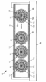
- FIG. 2 is a longitudinal sectional view of the multi-core cable in FIG. 1 taken along line XX. It is a top view of a multi-core cable.
- the multi-core cable 10 includes a plurality of coaxial cables 11 arranged in parallel, and ground members 15 and 16 that are conductively connected to the coaxial cables 11. That is, as shown in FIG. 2, the multi-core cable 10 is arranged in parallel, and the assembly of the plurality of coaxial cables 11 aligned in the axial direction is located at a position away from the tip in the axial direction by a predetermined distance. It is configured to be sandwiched between two ground members 15 and 16 from above and below.
- the inner conductor 11a of the coaxial cable 11 is appropriately bent, and is soldered to a corresponding one of the plurality of connected portions 30b provided on the connected member 30 at the solder portion 30c.
- the member 30 to be connected is not a board but a connector, that is, when the multi-core cable 10 is a multi-core cable with a connector, a shell of a metal plate having a U-shaped cross section is put on one ground member 15. And soldered.
- the shell is soldered to the ground member 15 by supplying solder from a solder introduction hole arranged on the upper surface.
- the ground member 15 is grounded by connecting both ends of the shell to the grounded connected portion of the connector.
- the multi-core cable 10 can take various forms such as a form in which connectors are provided at both ends, a form in which a connector is provided at one end, and a substrate is connected to the other end.
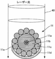
- the coaxial cable 11 includes an inner conductor 11a, an inner insulating layer 11b that covers the outer peripheral surface of the inner conductor 11a, an outer conductor 11c that covers the outer peripheral surface of the inner insulating layer 11b, and a coating that covers the outer peripheral surface of the outer conductor 11c. It has a layer 11d, a removal portion 11e from which a portion of the coating layer 11d in the circumferential direction is removed so as to expose the external conductor 11c, and a conductive member 21 filled in the removal portion 11e.
- the ground member 15 is conductively connected to the conductive member 21 filled in the removal portion 11e.
- the multi-core cable 10 configured as described above can achieve cost reduction by being formed by removing a part of the coating layer 11d by the removal portion 11e of the coaxial cable 11.
- the reason why the cost can be reduced will be described in detail.
- the external force applied to the coaxial cable 11 is reduced as compared with the case where the entire circumference of the covering layer 11d is removed.
- the resistance to external force is increased. Therefore, the probability that the coaxial cable 11 is damaged is reduced in an operation in which an external force is applied to the coaxial cable 11 such as the operation of removing the covering layer 11d or the terminal operation after the removal.
- the yield of the coaxial cable 11 is improved, the cost of the multi-core cable 10 can be reduced.
- the multi-core cable 10 configured as described above has the ground members 15 and 16 connected to the conductive members 21 of the coaxial cables arranged in parallel, with the removal portion 11e and the conductive member 21 filled in the removal portion 11e as marks. Are brought into contact with each other and conductively connected, whereby the positional relationship between the ground members 15 and 16 and the coaxial cable 11 can be positioned with high accuracy in the axial direction of the coaxial cable 11.
- the multi-core cable 10 can be arranged in parallel with a plurality of coaxial cables 11 with the removal portion 11e and the conductive member 21 filled in the removal portion 11e as a mark.
- the ground members 15 and 16 can be brought into contact with each other for conductive connection. In the present embodiment, the case where the ground members 15 and 16 are brought into contact with the conductive members 21 of the coaxial cables arranged in parallel will be described, but the present invention is not limited to this.
- Multi-core cable 10 Coaxial cable 11
- the coaxial cable 11 is formed by arranging the inner conductor 11a, the inner insulating layer 11b, the outer conductor 11c, and the covering layer 11d coaxially from the inner peripheral side toward the outer peripheral side.
- the end portion of the coaxial cable 11 is subjected to a lead-out process.
- the inner conductor 11a and the inner insulating layer 11b are exposed in a predetermined length stepwise from the front end side.
- the inner conductor 11a is formed, for example, by twisting seven copper alloy wires.
- the inner insulating layer 11b is formed by coating the outer surface of the inner conductor 11a with an insulating material such as Teflon (registered trademark) resin, which is a fluororesin.
- the inner insulating layer 11b is preferably made of “modified polyphenylene ether resin” or “mixed resin of cycloolefin resin and styrene / butadiene copolymer”. This is because these resins are easily evaporated by excimer laser light, and thus the removal portion 11e can be easily formed by excimer laser processing. Details will be described later.
- the outer conductor 11c is formed by, for example, winding a copper alloy wire in a spiral shape with a horizontal winding.
- the covering layer 11d is formed by, for example, winding two polyester tapes on the outer surface of the outer conductor 11c and fusing them together.
- the internal conductor 11a may be formed of a copper wire.
- the internal insulating layer 11b may be formed of a mixed resin of PVC (polyvinyl chloride), m-PPE (modified polyphenylene ether), COP (cycloolefin resin) and styrene-butadiene copolymer in addition to the fluororesin. .
- the outer conductor 11c and the covering layer 11d may be formed by winding the outer surface of the inner insulating layer 11b with the copper vapor deposition surface of the copper vapor deposition PET tape inside. Moreover, the outer conductor 11c may be formed by winding the copper alloy wire of the inner conductor 11a in opposite directions and wound around two layers, or may be formed by another structure.
- the outer conductor 11c may be formed of a conductive paste such as an Ag paste.
- the coating layer 11d may be formed of a fluororesin, a urethane resin, or a polycarbonate resin.
- the coaxial cable 11 As the coaxial cable 11, a cable corresponding to the AWG 42 of the AWG (American Wire Gage) standard is used. The outer diameter of the coaxial cable 11 of the AWG 42 is set to 0.31 mm.
- the inner conductor 11a is formed, for example, by twisting seven strands of tin-plated copper alloy having an outer diameter of 0.025 mm.
- the inner insulating layer 11b is formed by coating the outer peripheral surface of the inner conductor 11a with a fluororesin such as PFA (perfluoroalkoxy fluororesin). The outer diameter of the inner insulating layer 11b is set to 0.17 mm.
- the outer conductor 11c is formed by spirally winding a tin-plated copper alloy strand having an outer diameter of 0.03 mm around the outer peripheral surface of the inner insulating layer 11b.
- the outer diameter of the outer conductor 11c is set to 0.23 mm.
- the covering layer 11d is formed by covering the outer peripheral surface of the outer conductor 11c with a fluororesin such as PFA.
- the removal portion 11e exposes the outer peripheral surface of the outer conductor 11c by removing a part of the coating layer 11d in the circumferential direction.
- “removal of coating layer 11d” may be performed by any processing method, for example, using a laser beam or a drill.
- “exposing the outer conductor 11c” means an outer peripheral surface that is a radially outer peripheral surface of the outer conductor 11c, an inner peripheral surface that is a radially inner peripheral surface of the outer conductor 11c, and the outer conductor 11c. This means that at least one of the end faces, which are the cut surfaces, is exposed.
- “Exposure” means that the outer peripheral structure is removed from the outer space so that the inner peripheral structure such as the outer conductor 11c covered with the outer peripheral structure such as the covering layer 11d can be filled with the filler such as the conductive member 21 from the outer space. means.
- the removal part 11e is formed in the outer shape which removed the coating layer 11d in the ellipse shape.
- the ellipse-shaped removal portion 11 e has a major axis direction that matches the axial direction of the coaxial cable 11 and a major axis that matches the width of the ground member 15. Further, the removal portion 11 e is matched with the positioning position of the ground member 15 in the axial direction of the coaxial cable 11. As a result, all the removal portions 11e are arranged in a line in the arrangement direction of the coaxial cables 11. Therefore, by aligning both ends in the width direction of the ground member 15 with both ends in the major axis direction of these removal portions 11e, Positioning of the ground member 15 in the axial direction of the cable 11 can be easily performed with high accuracy.
- the removal part 11e should just be the hole shape by which the peripheral part was enclosed by the coating layer. That is, the hole shape of the removal part 11e is not limited to an elliptical shape, and may be a circular shape, a triangular shape, a quadrangular shape, or a polygonal shape.
- Multi-core cable 10 Coaxial cable 11: Modification of removal portion 11e
- the shape of the removal portion 11e may be a notch shape in which a part of the peripheral edge reaches the end surface of the coating layer 11d. It is preferable that the notch-shaped removal part 11e and the ground member 15 have the ends in the axial direction of the coaxial cable 11 aligned with each other.
- the coaxial cable 11 can be obtained by aligning one end in the width direction of the ground member 15 with the end portions of the removal portions 11e. It is possible to easily and accurately position the ground member 15 in the axial direction.
- the removal portion 11 e may have a plurality of uneven portions 11 f formed in the axial direction of the coaxial cable 11.
- the axis of the coaxial cable 11 is changed. Positioning of the ground member 15 in the direction can be easily performed with high accuracy.
- the uneven portion 11f of the removal portion 11e irradiates a plurality of laser beams 40 at a time such that the irradiation surface of the laser beam 40 overlaps in the axial direction of the coaxial cable 11 or one or more laser beams 40.
- a plurality of removal portions 11 e may be arranged in the circumferential direction of the coaxial cable 11. In this case, even when the removal portion 11e is deviated from an appropriate position in the circumferential direction due to twisting or distortion of the coaxial cable 11, the possibility of occurrence of a problem can be reduced.
- the plurality of removal portions 11e may have the same shape or different shapes. Furthermore, the removal portions 11e may have the same or different removal depths. Further, the plurality of removal portions 11e in the circumferential direction may be concentrated at one place as shown in FIG. 5, or may be evenly arranged in the circumferential direction as shown in FIG.
- the removal depth of the removal portion 11 e is set to such an extent that the outer peripheral surface of the external conductor 11 c is exposed is described, but the present invention is not limited thereto. is not.
- the removal depth of the removal portion 11e is such that the end surface of the external conductor 11c is exposed by setting the bottom surface of the removal portion 11e to the internal insulating layer 11b. It may be.
- the removal part 11e may be formed in the frustum shape which makes the outer peripheral surface side of the coating layer 11d the maximum diameter. In this case, since the removal part 11e becomes a reverse frustum shape, the operation
- the removal portion 11e is formed by irradiating the laser beam 40 so that the center of the laser beam 40 coincides with the apex of the coaxial cable 11.
- the present invention is not limited to this. Specifically, as shown in FIG. 10, even if the removal portion 11 e is formed by irradiating the laser beam 40 to a region where the apex of the coaxial cable 11 is removed, the side surface side of the coaxial cable 11 is removed. Good. 7 to 10 show a state in which the removal member 11e is filled with the conductive member 21.
- the laser beam 40 having a diameter smaller than the width of the coaxial cable 11 may be scanned in the width direction of the coaxial cable 11 to form more than half of the circumferential direction of the coaxial cable 11 as the removal portion 11e.
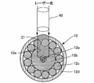
- the multi-core cable 10 of the present embodiment further includes a ground coaxial cable 12. That is, in the multi-core cable 10, at least one of the plurality of coaxial cables 11 is set as the ground coaxial cable 12. More specifically, as shown in FIG. 12, the ground coaxial cable 12 covers the inner conductor 12a, the inner insulating layer 12b covering the outer peripheral surface of the inner conductor 12a, and the outer peripheral surface of the inner insulating layer 12b.
- the removal part 12e exposes the internal conductor 12a and the external conductor 12c
- the internal conductor 12a and the external conductor 12c are electrically conductive by the conductive member 21 filled in the removal part 12e.
- the cross-sectional area of the internal conductor 11a (12a) and the external conductor 11c (12c) Since the total value with the cross-sectional area of the current can be the cross-sectional area of the current flow path, it can be used as a cable for ground short circuit with reduced electric resistance.
- the ground coaxial cable 12 removes the coating layer 12d, the outer conductor 12c, and the inner insulating layer 12b so that the laser beam 40 reaches the inner conductor 12a, thereby removing the laser beam 40 from the irradiation surface of the coating layer 12d.
- a removal portion 12e is formed in a region up to the inner conductor 12a. That is, the removal portion 12e is formed so as to reach the internal conductor 12a at a depth of the radius of the ground coaxial cable 12.
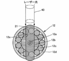
- the ground coaxial cable 12 is removed at the depth of the diameter of the ground coaxial cable 12 by passing the coaxial cable 11 through the inner conductor 12a by the laser light 40 as shown in FIG.
- the part 12e may be formed.
- the multi-core cable 10 may not include the ground coaxial cable 12. That is, the multi-core cable 10 may include only the coaxial cable 11.
- the conductive member 21 is formed of a conductive member such as a conductive paint or solder.
- the conductive member 21 is required to be in a paste state at the time of filling and in a solidified state when used as the multi-core cable 10 so that the removal part 11e can be easily filled.
- Examples of the conductive member 21 include solder that changes between a molten state and a solidified state by heat.
- the conductive member 21 may be a conductive paste such as a paste-like conductive adhesive, conductive ink, or conductive paint at the time of filling.
- a conductive paste in which metal particles, an organic solvent, and a resin are mixed can be used.
- the metal particles include silver and silver-coated copper powder (spherical and flaky).
- the organic solvent include ethyl acetate, toluene, acetone, ethyl methyl ketone, and hexane.
- the resin include an epoxy resin and a phenol resin.
- connection work of the ground members 15 and 16 to the outer conductor 11c that is, the filling of the conductive member 21 into the removal portion 11e and the connection of the ground members 15 and 16 to the coaxial cable 11 are performed with the conductive paste.
- the multi-core cable 10 including the coaxial cable 11 and the ground coaxial cable 12 includes ground members 15 and 16.
- These ground members 15 and 16 are provided so that the arrangement direction of the coaxial cable 11 and the ground coaxial cable 12 is a longitudinal direction, and are arranged so as to sandwich the coaxial cable 11 and the ground coaxial cable 12 from above and below. Yes.
- the ground members 15 and 16 are set to a length capable of contacting all the coaxial cables 11 and the ground coaxial cables 12 and are formed in a square plate shape having a constant thickness.
- the ground members 15 and 16 are formed of a conductive metal plate such as a copper plate. A solder layer formed by applying solder is provided on one surface of the ground members 15 and 16.
- the manufacturing method of the multi-core cable 10 includes an inner conductor 11a, an inner insulating layer 11b that covers the outer peripheral surface of the inner conductor 11a, an outer conductor 11c that covers the outer peripheral surface of the inner insulating layer 11b, and an outer peripheral surface of the outer conductor 11c.
- the removing portion 11e is formed by removing a part of the covering layer 11d in the circumferential direction so as to expose the outer conductor 11c.
- the ground members 15 and 16 are conductively connected to the conductive member 21 filled in the removal portion 11e.
- the coaxial cable 11 is damaged when the covering layer 11d is removed, by removing a part of the covering layer 11d as compared with the conventional case where the entire circumference of the covering layer 11d is removed. Since the frequency is reduced and the yield is improved, the cost of the multi-core cable 10 can be reduced.
- a removal part is formed with a laser beam. In this case, it is because the removal part 11e can be formed easily.
- a laser beam 40 such as an excimer laser beam is sequentially irradiated onto the coaxial cable 11 to form the removal portion 11e so that the external conductor 11c is exposed.
- the inner insulating layer 11b is preferably a modified polyphenylene ether resin or a cycloolefin polymer resin.
- the laser beam 40 is used as a removal portion 12e that reaches the internal conductor 12a, so that the external The conductor 12c and the inner conductor 12a are exposed.
- a plurality of coaxial cables 11 and one or more ground coaxial cables 12 are formed (removal portion forming step).
- the removing members 11e and 12e are filled with the conductive member 21.
- the removing portions 11e and 12e are filled with a conductive paint (filling step).
- the coating layers 11d and 12d and the outer conductors 11c and 12c are cut by adjusting the wavelength and intensity of laser light such as YAG laser, CO2 laser, and excimer laser. Pull out the end side and remove it.
- the internal insulating layers 11b and 12b are cut by adjusting the wavelength and intensity of the laser beam, and the internal insulating layers 11b and 12b on the end side are pulled out and removed (outlet process).
- the coaxial cable 11 and the ground coaxial cable 12 are sandwiched between the ground members 15 and 16, and the ground members 15 and 16 are inserted into the removal portions 11e and 12e of the coaxial cable 11 and the ground coaxial cable 12.
- the conductive member 21 filled is brought into contact.
- the ground members 15 and 16 are set so that the solder layer side faces the coaxial cable 11 side. Then, heating is performed while maintaining the state sandwiched between the ground members 15 and 16, the solder layer of the ground members 15 and 16 is melted, and the conductive member 21 and the ground members 15 and 16 of the coaxial cable 11 and the ground coaxial cable 12 are Are electrically connected (soldering process).
- the multi-core cable 10 whose ends are assembled and integrated is connected to a connected member 30 such as a connector terminal or a board (such as an FPC).
- a connected member 30 such as a connector terminal or a board (such as an FPC).
- the end grounding portions located at both ends of the ground members 15 and 16 are soldered and electrically connected to the grounded connected portion 30a.
- the inner conductors 11a and 12a of the coaxial cable 11 and the ground coaxial cable 12 are appropriately bent and soldered to the corresponding connected portions 30b by the solder portions 30c, so that the inner conductor 11a and the connected portion 30b are electrically connected. Connected.
- the connected member 30 is a connector
- a metal plate shell is placed on one ground member 15 and soldered.
- the ground member 15 is grounded by connecting the shell to the connected portion for grounding the connector.
- both ends of the ground members 15 and 16 are soldered and electrically connected.
- the multi-core cable 10 is in the form of a multi-core cable with a connector.
- the manufacturing method of the multi-core cable 10 includes an inner conductor 11a, an inner insulating layer 11b covering the outer peripheral surface of the inner conductor 11a, and an outer peripheral surface of the inner insulating layer 11b.
- the coaxial cable 11 having the outer conductor 11c to be covered and the covering layer 11d that covers the outer peripheral surface of the outer conductor 11c a portion of the covering layer 11d in the circumferential direction is removed so that the outer conductor 11c is exposed.
- the conductive member 21 is formed by filling the removal portion 11e with the conductive paste 60 in a state where a plurality of the coaxial cables 11 are arranged in parallel, and the ground member is formed with the conductive paste. It may be formed.
- the above manufacturing method has the following effects in addition to the effects when the plate-like ground members 15 and 16 are used. That is, by arranging a plurality of coaxial cables 11 in parallel and filling the removal portions 11e of these coaxial cables 11 with a conductive paste to form a conductive member 21 and a ground member, a plate-like ground member 15 is formed. Compared with the case where 16 is used, the conductive paste 60 is used to connect the ground member to the outer conductor 11c, that is, to fill the removal portion 11e of the conductive member 21 and to connect the ground member to the coaxial cable 11. Can be completed in one step, and therefore the workability is excellent.
- sample pieces corresponding to the respective portions of the coaxial cable 11 were prepared using the materials shown in Table 1. More specifically, sample pieces corresponding to the inner insulating layer 11b include fluororesin, polyvinyl chloride resin (PVC), modified polyphenylene ether resin (m-PPE), cycloolefin resin (COP), and COP.
- PVC polyvinyl chloride resin
- m-PPE modified polyphenylene ether resin
- COP cycloolefin resin
- a sample piece corresponding to the coating layer 11d was prepared by forming a fluororesin, a urethane resin, and a polycarbonate resin into a square sheet shape having a thickness of 50 ⁇ m.
- Each of the above sample pieces was examined for workability when irradiated with CO2 laser light, YAG laser light, and excimer laser light.
- the laser light irradiation conditions were as follows: irradiation time was 5 seconds, irradiation area was a square of 250 ⁇ m (vertical) ⁇ 250 ⁇ m (horizontal), and was the same for all laser beams.
- the workability does not react to the laser beam, the evaluation that the sample piece penetrated in the thickness direction by the laser light irradiation ( ⁇ ), the evaluation that the sample piece did not penetrate in the thickness direction ( ⁇ ), and the laser beam. It was divided into three grades of evaluation ( ⁇ ).
- the excimer laser beam has good processability for the m-PPE sample piece, the Ag paste sample piece, the urethane resin sample piece, and the polycarbonate resin sample piece. It was found to have (evaluation ⁇ ).
- excimer laser light has low processability (evaluation x) for 100% COP resin, but it is a mixed resin of COP and styrene-butadiene copolymer (100: 10, 100: 25, 10: 100). It was found that the sample piece had good workability (evaluation ⁇ ).
- the coaxial cable 11 is constituted by the inner insulating layer 11b of the mixed resin of m-PPE or COP and the styrene / butadiene copolymer, the outer conductor 11c of the Ag paste, and the covering layer 11d of the urethane resin or the polycarbonate resin. It has been found that when the coaxial cable 11 is processed with an excimer laser beam, the removal portion 11e can be formed satisfactorily.
Landscapes
- Physics & Mathematics (AREA)
- Spectroscopy & Molecular Physics (AREA)
- Engineering & Computer Science (AREA)
- Manufacturing & Machinery (AREA)
- Insulated Conductors (AREA)
- Communication Cables (AREA)
- Multi-Conductor Connections (AREA)
- Manufacturing Of Electric Cables (AREA)
Abstract
被覆層を除去する際の同軸ケーブルの破損頻度を低減して多心ケーブルをコストダウンする。多心ケーブル10は、並列配置された複数の同軸ケーブル11と、これら同軸ケーブル11に導電接続されたグランド部材15・16とを備えている。同軸ケーブル11は、内部導体11aと、内部導体11aの外周面を被覆する内部絶縁層11bと、内部絶縁層11bの外周面を被覆する外部導体11cと、外部導体11cの外周面を被覆する被覆層11dと、外部導体11cを露出させるように被覆層11dにおける周方向の一部が除去された除去部11eと、除去部11eに充填された導電部材21とを有している。グランド部材15は、除去部11eに充填された導電部材21に導電接続されている。
Description
本発明は、並列に配置した複数の同軸ケーブルを有する多心ケーブル及び多心ケーブルの製造方法に関する。
ノートパソコンや携帯電話機、小型ビデオカメラ等の電子機器の普及により、これら電子機器の小型・軽量化の他に、高速・高画質化が求められている。そこで、従来から、機器本体と液晶表示部との接続や機器内の配線などに、極めて細い同軸ケーブルが用いられ、また、配線の容易性から、複数本の同軸ケーブルを集合一体化させたハーネス形状の多心ケーブルが用いられている(特許文献1等)。
ところで、電子機器は、小型・軽量化及び高速・高画質化に加えて、低コストであることも求められていることから、電子機器に搭載される多心ケーブルに対してもコストダウンが求められている。
本発明の目的は、コストダウンすることが可能な多心ケーブル及び多心ケーブルの製造方法を提供することである。
本発明は、並列配置された複数の同軸ケーブルと、これら同軸ケーブルに導電接続されたグランド部材とを備えた多心ケーブルであって、
前記同軸ケーブルは、内部導体と、前記内部導体の外周面を被覆する内部絶縁層と、前記内部絶縁層の外周面を被覆する外部導体と、前記外部導体の外周面を被覆する被覆層と、前記外部導体を露出させるように前記被覆層における周方向の一部が除去された除去部と、前記除去部に充填された導電部材とを有しており、
前記グランド部材は、前記除去部に充填された前記導電部材に導電接続されている。
前記同軸ケーブルは、内部導体と、前記内部導体の外周面を被覆する内部絶縁層と、前記内部絶縁層の外周面を被覆する外部導体と、前記外部導体の外周面を被覆する被覆層と、前記外部導体を露出させるように前記被覆層における周方向の一部が除去された除去部と、前記除去部に充填された導電部材とを有しており、
前記グランド部材は、前記除去部に充填された前記導電部材に導電接続されている。
上記の構成によれば、被覆層の一部を除去することによって、被覆層の全周を除去する場合よりも、被覆層を除去する際の同軸ケーブルの破損頻度が低減して歩留まりが向上することから多心ケーブルのコストダウンを実現することができる。
本発明における前記除去部は、穴形状に形成されていてもよい。
上記の構成によれば、ドリルやレーザ光による穴開け加工により所望位置に対して容易且つ高精度に除去部を形成することができる。
本発明における前記除去部は、被覆層の外周面側を最大径とする錐台形状に形成されていてもよい。
上記の構成によれば、除去部に導電部材を充填する作業が容易である。
本発明における前記同軸ケーブルの少なくとも一つは、前記除去部が、さらに前記内部導体を露出させていてもよい。
上記の構成によれば、除去部が内部導体と外部導体とを露出させることによって、除去部に充填された導電部材により内部導体と外部導体とが電気的に導通状態にされる。これにより、同一の同軸ケーブルを用いて多心ケーブルを形成しつつ、少なくとも一つの同軸ケーブルについては内部導体の断面積と外部導体の断面積との合計値を電流の流路断面積にすることができるため、電気抵抗の低減したグランド短絡用のケーブルとして用いることができる。
本発明における前記グランド部材と前記導電部材とは、導電性ペーストにより形成されていてもよい。
上記の構成によれば、グランド部材に板状のグランドバーを用いる場合と比較して、グランド部材の外部導体への接続作業、即ち、導電部材の除去部への充填と、グランド部材の同軸ケーブルへの接続とを導電性ペーストにより1工程で完了することができるため、作業性の優れたものとなる。
本発明において、前記同軸ケーブルにおける前記内部絶縁層が、変性ポリフェニレンエーテル、又はシクロオレフィン樹脂とスチレン・ブタジエン共重合体との混合樹脂であってもよい。
上記の構成によれば、変性ポリフェニレンエーテル樹脂がエキシマレーザ光により蒸発し易いため、除去部をエキシマレーザ加工により容易に形成することができる。
本発明は、並列配置された複数の同軸ケーブルと、これら同軸ケーブルに導電接続されたグランド部材とを備えた多心ケーブルの製造方法であって、
内部導体と、前記内部導体の外周面を被覆する内部絶縁層と、前記内部絶縁層の外周面を被覆する外部導体と、前記外部導体の外周面を被覆する被覆層とを有した同軸ケーブルに対して、前記外部導体を露出させるように前記被覆層における周方向の一部を除去することにより除去部を形成した後、前記除去部に導電部材を充填し、
前記同軸ケーブルの複数を並列配置した状態で、前記除去部に充填された前記導電部材に前記グランド部材を導電接続させる。
内部導体と、前記内部導体の外周面を被覆する内部絶縁層と、前記内部絶縁層の外周面を被覆する外部導体と、前記外部導体の外周面を被覆する被覆層とを有した同軸ケーブルに対して、前記外部導体を露出させるように前記被覆層における周方向の一部を除去することにより除去部を形成した後、前記除去部に導電部材を充填し、
前記同軸ケーブルの複数を並列配置した状態で、前記除去部に充填された前記導電部材に前記グランド部材を導電接続させる。
上記の構成によれば、被覆層の一部を除去することによって、従来のように被覆層の全周を除去する場合よりも、被覆層を除去する際の同軸ケーブルの破損頻度が低減して歩留まりが向上することから多心ケーブルをコストダウンすることができる。
本発明における前記除去部が、レーザ光により形成されてもよい。
上記の構成によれば、除去部を容易に形成することができる。
本発明は、並列配置された複数の同軸ケーブルと、これら同軸ケーブルに導電接続されたグランド部材とを備えた多心ケーブルの製造方法であって、
内部導体と、前記内部導体の外周面を被覆する内部絶縁層と、前記内部絶縁層の外周面を被覆する外部導体と、前記外部導体の外周面を被覆する被覆層とを有した同軸ケーブルに対して、前記外部導体を露出させるように前記被覆層における周方向の一部を除去することにより除去部を形成した後、
前記同軸ケーブルの複数を並列配置した状態で、導電性ペーストを前記除去部に充填する。
内部導体と、前記内部導体の外周面を被覆する内部絶縁層と、前記内部絶縁層の外周面を被覆する外部導体と、前記外部導体の外周面を被覆する被覆層とを有した同軸ケーブルに対して、前記外部導体を露出させるように前記被覆層における周方向の一部を除去することにより除去部を形成した後、
前記同軸ケーブルの複数を並列配置した状態で、導電性ペーストを前記除去部に充填する。
上記の構成によれば、被覆層の除去部を目印にすることによって、並列配置された同軸ケーブルの軸方向の位置合わせを容易且つ高精度に行うことができる。さらに、複数の同軸ケーブルを並列配置し、これらの同軸ケーブルの除去部に導電性ペーストを充填して導電部材を形成すると共にグランド部材を形成することによって、グランド部材に板状のグランドバーを用いる場合と比較して、グランド部材の外部導体への接続作業、即ち、導電部材の除去部への充填と、グランド部材の同軸ケーブルへの接続とを導電性ペーストにより1工程で完了することができるため、作業性の優れたものとなる。
本発明によると、被覆層を除去する際の同軸ケーブルの破損頻度が低減して歩留まりが向上することから多心ケーブルをコストダウンすることができる。
以下、本発明の好適な実施形態について、図面を参照しつつ説明する。
(多心ケーブル10)
図1に示すように、多心ケーブル10は、並列配置された複数の同軸ケーブル11と、これら同軸ケーブル11に導電接続されたグランド部材15・16とを備えている。即ち、図2にも示すように、多心ケーブル10は、並列配置され、且つ軸方向に位置合わせされた複数の同軸ケーブル11の集合体が、先端から軸方向に所定距離を離れた位置において上下方向から2つのグランド部材15・16により挟持された構成にされている。
図1に示すように、多心ケーブル10は、並列配置された複数の同軸ケーブル11と、これら同軸ケーブル11に導電接続されたグランド部材15・16とを備えている。即ち、図2にも示すように、多心ケーブル10は、並列配置され、且つ軸方向に位置合わせされた複数の同軸ケーブル11の集合体が、先端から軸方向に所定距離を離れた位置において上下方向から2つのグランド部材15・16により挟持された構成にされている。
多心ケーブル10は、同軸ケーブル11の内部導体11aが適宜曲げられ、被接続部材30に設けられた複数の被接続部30bのうちの対応する一つに半田部30cにおいて半田付けされている。尚、被接続部材30が基板ではなくコネクタである場合、すなわち多心ケーブル10がコネクタ付き多心ケーブルである場合は、一方のグランド部材15の上に断面コ字状の金属板のシェルが被せられて半田付けされる。シェルは、上面に配置された半田導入用穴から半田が投入されることによって、グランド部材15に半田付けされる。そして、このシェルの両先端がコネクタの接地用の被接続部に接続されることによって、グランド部材15の接地がなされる。
尚、多心ケーブル10は、両端部にコネクタが設けられた形態や、一端部にコネクタが設けられ、他端部に基板が接続された形態等のように様々な形態を採り得る。
同軸ケーブル11は、内部導体11aと、内部導体11aの外周面を被覆する内部絶縁層11bと、内部絶縁層11bの外周面を被覆する外部導体11cと、外部導体11cの外周面を被覆する被覆層11dと、外部導体11cを露出させるように被覆層11dにおける周方向の一部が除去された除去部11eと、除去部11eに充填された導電部材21とを有している。グランド部材15は、除去部11eに充填された導電部材21に導電接続されている。
上記のように構成された多心ケーブル10は、同軸ケーブル11の除去部11eが被覆層11dの一部を除去することにより形成されることによって、コストダウンを実現することができる。コストダウンを実現できる理由を詳細に説明すると、被覆層11dの一部を除去する場合は、被覆層11dの全周を除去する場合よりも、同軸ケーブル11にかかる外力が低減される。また、除去量が少なくなるので、外力に対する抵抗力が高くなる。従って、被覆層11dの除去作業や、除去後の端末作業等のような同軸ケーブル11に外力がかかる作業において、同軸ケーブル11が破損する確率が低減する。この結果、同軸ケーブル11の歩留まりが向上することから多心ケーブル10のコストダウンを実現することができる。
さらに、上記のように構成された多心ケーブル10は、除去部11eや除去部11eに充填された導電部材21を目印にして、並列配置された同軸ケーブルの導電部材21にグランド部材15・16を当接して導電接続することによって、グランド部材15・16と同軸ケーブル11との位置関係を、同軸ケーブル11の軸方向において高精度に位置決めすることができる。また、多心ケーブル10は、除去部11eや除去部11eに充填された導電部材21を目印にして、複数の同軸ケーブル11を並列配置することができると共に、これらの同軸ケーブルの導電部材21にグランド部材15・16を当接して導電接続することができる。尚、本実施形態においては、並列配置された同軸ケーブルの導電部材21にグランド部材15・16を当接する場合について説明するが、これに限定されるものではない。
(多心ケーブル10:同軸ケーブル11)
同軸ケーブル11は、上述のように、内部導体11aと内部絶縁層11bと外部導体11cと被覆層11dとを、内周側から外周側に向けて同軸で配置することにより形成されている。同軸ケーブル11の端部は、口出し処理が施されている。これにより、同軸ケーブル11は、先端側から順に、内部導体11aと内部絶縁層11bとがそれぞれ段階的に所定長で露出されている。
同軸ケーブル11は、上述のように、内部導体11aと内部絶縁層11bと外部導体11cと被覆層11dとを、内周側から外周側に向けて同軸で配置することにより形成されている。同軸ケーブル11の端部は、口出し処理が施されている。これにより、同軸ケーブル11は、先端側から順に、内部導体11aと内部絶縁層11bとがそれぞれ段階的に所定長で露出されている。
内部導体11aは、例えば銅合金線を7本撚って形成されている。内部絶縁層11bは、内部導体11aの外面をフッ素樹脂であるテフロン(登録商標)樹脂等の絶縁材で被覆することにより形成されている。内部絶縁層11bは、「変性ポリフェニレンエーテル樹脂」や「シクロオレフィン樹脂とスチレン・ブタジエン共重合体の混合樹脂」を使用することが好ましい。この理由は、これらの樹脂がエキシマレーザ光により蒸発し易いため、除去部11eをエキシマレーザ加工により容易に形成することができるからである。詳細は後述する。
外部導体11cは、例えば銅合金線を横巻きで螺旋状に巻き付けることにより形成されている。被覆層11dは、外部導体11cの外面に例えばポリエステルテープを2枚重ね巻きして互いに融着することにより形成されている。尚、内部導体11aは、銅線で形成されていてもよい。内部絶縁層11bは、フッ素樹脂の他、PVC(polyvinyl chloride)や、m-PPE(変性ポリフェニレンエーテル)、COP(シクロオレフィン樹脂)とスチレン・ブタジエン共重合体の混合樹脂で形成されていてもよい。外部導体11c及び被覆層11dは、内部絶縁層11bの外周面に銅蒸着PETテープの銅蒸着面を内側にして巻き付けることにより形成されていてもよい。また、外部導体11cは、内部導体11aの銅合金線の巻方向を反対にして2層に巻き付けることにより形成されていてもよいし、その他の構造で形成されていてもよい。外部導体11cは、Agペースト等の導電性ペーストにより形成されていてもよい。被覆層11dは、フッ素樹脂やウレタン樹脂、ポリカーボネート樹脂で形成されていてもよい。
同軸ケーブル11の一例を具体的に説明すると、同軸ケーブル11は、AWG(American Wire Gage)規格のAWG42に該当するケーブルが用いられている。AWG42の同軸ケーブル11の外径は、0.31mmに設定されている。内部導体11aは、例えば外径0.025mmの錫メッキ銅合金の素線を7本撚ることにより形成されている。内部絶縁層11bは、内部導体11aの外周面をPFA(ペルフルオロアルコキシフッ素樹脂)等のフッ素樹脂で被覆することにより形成されている。内部絶縁層11bの外径は、0.17mmに設定されている。外部導体11cは、内部絶縁層11bの外周面に外径0.03mmの錫メッキ銅合金の素線を螺旋状に巻き付けることにより形成されている。外部導体11cの外径は、0.23mmに設定されている。被覆層11dは、外部導体11cの外周面をPFA等のフッ素樹脂で被覆することにより形成されている。
(多心ケーブル10:同軸ケーブル11:除去部11e)
除去部11eは、被覆層11dにおける周方向の一部を除去することによって、外部導体11cの外周面を露出させている。ここで、『被覆層11dの除去』は、どのような加工方法で行われてもよく、例えばレーザ光やドリルを用いて行われてもよい。ここで、『外部導体11cを露出』とは、外部導体11cにおける径方向の外側の周面である外周面、外部導体11cにおける径方向の内側の周面である内周面、及び外部導体11cの切断面である端面の少なくとも一つを露出させることを意味する。『露出』は、被覆層11d等の外周構造物で覆われた外部導体11c等の内周構造物について、導電部材21等の充填物を外部空間から充填可能に外周構造物を除去することを意味する。
除去部11eは、被覆層11dにおける周方向の一部を除去することによって、外部導体11cの外周面を露出させている。ここで、『被覆層11dの除去』は、どのような加工方法で行われてもよく、例えばレーザ光やドリルを用いて行われてもよい。ここで、『外部導体11cを露出』とは、外部導体11cにおける径方向の外側の周面である外周面、外部導体11cにおける径方向の内側の周面である内周面、及び外部導体11cの切断面である端面の少なくとも一つを露出させることを意味する。『露出』は、被覆層11d等の外周構造物で覆われた外部導体11c等の内周構造物について、導電部材21等の充填物を外部空間から充填可能に外周構造物を除去することを意味する。
図1に示すように、除去部11eは、被覆層11dを楕円形状に除去した外形状に形成されている。楕円形状の除去部11eは、長径方向が同軸ケーブル11の軸方向に一致され、且つ、長径がグランド部材15の幅に一致されている。さらに、除去部11eは、同軸ケーブル11の軸方向におけるグランド部材15の位置決め位置に一致されている。これにより、全ての除去部11eが同軸ケーブル11の配列方向に一列状に配置されるため、これらの除去部11eの長径方向の両端部にグランド部材15の幅方向の両端を合わせることによって、同軸ケーブル11の軸方向におけるグランド部材15の位置決めを高精度且つ容易に行うことが可能になる。
尚、除去部11eは、周縁部が被覆層で囲まれた穴形状であればよい。即ち、除去部11eの穴形状は、楕円形状に限定されるものではなく、円形状や三角形状、四角形状、多角形状であってもよい。
(多心ケーブル10:同軸ケーブル11:除去部11eの変形例)
本実施形態おいては、除去部11eが穴形状に形成された場合について説明しているが、これに限定されるものではない。具体的には、図3に示すように、除去部11eの形状は、周縁部の一部が被覆層11dの端面に到達した切り欠き形状であってもよい。切り欠き形状の除去部11eとグランド部材15とは、同軸ケーブル11の軸方向における端部同士が一致されていることが好ましい。この場合は、全ての除去部11eが同軸ケーブル11の配列方向に一列状に配置されるため、これらの除去部11eの端部にグランド部材15の幅方向の一端を合わせることによって、同軸ケーブル11の軸方向におけるグランド部材15の位置決めを高精度且つ容易に行うことが可能になる。
本実施形態おいては、除去部11eが穴形状に形成された場合について説明しているが、これに限定されるものではない。具体的には、図3に示すように、除去部11eの形状は、周縁部の一部が被覆層11dの端面に到達した切り欠き形状であってもよい。切り欠き形状の除去部11eとグランド部材15とは、同軸ケーブル11の軸方向における端部同士が一致されていることが好ましい。この場合は、全ての除去部11eが同軸ケーブル11の配列方向に一列状に配置されるため、これらの除去部11eの端部にグランド部材15の幅方向の一端を合わせることによって、同軸ケーブル11の軸方向におけるグランド部材15の位置決めを高精度且つ容易に行うことが可能になる。
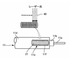
図4に示すように、除去部11eは、同軸ケーブル11の軸方向において複数の凹凸部11fが形成されていてもよい。この場合は、グランド部材15の一端や両端を凹凸部11fの何れかの凹部や凸部に合わせることによって、設計変更等によりグランド部材15の設置位置が変更された場合でも、同軸ケーブル11の軸方向におけるグランド部材15の位置決めを高精度且つ容易に行うことが可能になる。尚、除去部11eの凹凸部11fは、レーザ光40の照射面が同軸ケーブル11の軸方向において重複するように、複数のレーザ光40を一度に照射したり、或いは、1以上のレーザ光40を1照射毎に同軸ケーブル11の軸方向にずらして照射する操作を繰り返すことにより行うことができる。
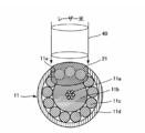
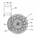
図5及び図6に示すように、また、複数の除去部11eが同軸ケーブル11の周方向に配置されていてもよい。この場合は、同軸ケーブル11の捻じれや歪み等により除去部11eが周方向の適正位置から外れた場合でも、不具合が生じる可能性を低減することができる。尚、複数の除去部11eは、同一形状であってもよいし、異なる形状であってもよい。さらに、複数の除去部11eは、除去深さが同一であってもよいし、異なっていてもよい。また、周方向の複数の除去部11eは、図5に示すように一箇所に集中して配置されていてもよいし、図6に示すように周方向に均等に配置されていてもよい。
本実施形態おいては、図7に示すように、除去部11eの除去深さが外部導体11cの外周面を露出させる程度に設定された場合について説明しているが、これに限定されるものではない。具体的には、図8に示すように、除去部11eの除去深さは、除去部11eの底面が内部絶縁層11bに設定されることによって、外部導体11cの端面が露出されるようになっていてもよい。さらに、図9に示すように、除去部11eは、被覆層11dの外周面側を最大径とする錐台形状に形成されていてもよい。この場合は、除去部11eが逆錐台形状になるため、導電部材21を充填する作業が容易になる。
本実施形態においては、同軸ケーブル11の頂点にレーザ光40の中心が一致させるように、レーザ光40を照射させることにより除去部11eを形成しているが、これに限定されるものではない。具体的には、図10に示すように、同軸ケーブル11の頂点を外した領域にレーザ光40を照射することによって、同軸ケーブル11の側面側を除去することで除去部11eを形成してもよい。尚、図7~図10は、除去部11eに導電部材21が充填された状態を示している。
さらに、図11に示すように、同軸ケーブル11の幅よりも大きな直径のレーザ光40を、同軸ケーブル11に照射することによって、同軸ケーブル11の周方向の半分以上を除去部11eとして形成してもよい。また、同軸ケーブル11の幅よりも小さな直径のレーザ光40を同軸ケーブル11の幅方向に走査することによって、同軸ケーブル11の周方向の半分以上を除去部11eとして形成してもよい。
(多心ケーブル10:グランド用同軸ケーブル12)
図1及び図2に示すように、本実施形態の多心ケーブル10は、さらに、グランド用同軸ケーブル12を有している。即ち、多心ケーブル10は、複数の同軸ケーブル11の少なくとも一つがグランド用同軸ケーブル12に設定されている。具体的に説明すると、グランド用同軸ケーブル12は、図12に示すように、内部導体12aと、内部導体12aの外周面を被覆する内部絶縁層12bと、内部絶縁層12bの外周面を被覆する外部導体12cと、外部導体12cの外周面を被覆する被覆層12dと、外部導体12c及び内部導体12aを露出させるように被覆層12dにおける周方向の一部が除去された除去部12eと、除去部12eに充填された導電部材21とを有している。
図1及び図2に示すように、本実施形態の多心ケーブル10は、さらに、グランド用同軸ケーブル12を有している。即ち、多心ケーブル10は、複数の同軸ケーブル11の少なくとも一つがグランド用同軸ケーブル12に設定されている。具体的に説明すると、グランド用同軸ケーブル12は、図12に示すように、内部導体12aと、内部導体12aの外周面を被覆する内部絶縁層12bと、内部絶縁層12bの外周面を被覆する外部導体12cと、外部導体12cの外周面を被覆する被覆層12dと、外部導体12c及び内部導体12aを露出させるように被覆層12dにおける周方向の一部が除去された除去部12eと、除去部12eに充填された導電部材21とを有している。
上記の構成によれば、除去部12eが内部導体12aと外部導体12cとを露出させることによって、除去部12eに充填された導電部材21により内部導体12aと外部導体12cとが電気的に導通状態にされる。これにより、同一の同軸ケーブル11を用いて多心ケーブルを形成しつつ、少なくとも一つの同軸ケーブル11(グランド用同軸ケーブル12)については内部導体11a(12a)の断面積と外部導体11c(12c)の断面積との合計値を電流の流路断面積にすることができるため、電気抵抗の低減したグランド短絡用のケーブルとして用いることができる。
グランド用同軸ケーブル12は、レーザ光40が内部導体12aに到達するように、被覆層12dと外部導体12cと内部絶縁層12bとを除去することによって、レーザ光40の被覆層12dにおける照射面から内部導体12aまでの領域に除去部12eが形成されている。即ち、除去部12eは、グランド用同軸ケーブル12の半径の深さで内部導体12aに到達するように形成されている。尚、グランド用同軸ケーブル12は、図13に示すように、レーザ光40により内部導体12aを通過するように同軸ケーブル11が貫通されることによって、グランド用同軸ケーブル12の直径の深さで除去部12eが形成されていてもよい。また、多心ケーブル10は、グランド用同軸ケーブル12を備えていなくてもよい。即ち、多心ケーブル10は、同軸ケーブル11だけを備えていてもよい。
(多心ケーブル10:同軸ケーブル11:導電部材21)
導電部材21は、導電性塗料や半田等の導電性を有した部材により形成されている。尚、導電部材21は、除去部11eに容易に充填できるように、充填時においてペースト状態であり、多心ケーブル10として使用時において、固化状態であることが条件とされる。導電部材21としては、例えば熱により溶融状態と固化状態とに変化する半田が例示される。
導電部材21は、導電性塗料や半田等の導電性を有した部材により形成されている。尚、導電部材21は、除去部11eに容易に充填できるように、充填時においてペースト状態であり、多心ケーブル10として使用時において、固化状態であることが条件とされる。導電部材21としては、例えば熱により溶融状態と固化状態とに変化する半田が例示される。
また、導電部材21としては、充填時においてペースト状の導電性接着剤や導電性インク、導電性塗料等の導電性ペーストであってもよい。具体的には、導電性ペーストは、金属粒子、有機溶媒、及び樹脂を混合させたものを適用することができる。金属粒子としては、銀や銀コート銅粉(球状、フレーク状)が例示される。有機溶媒としては、酢酸エチルやトルエン、アセトン、エチルメチルケトン、ヘキサンが例示される。樹脂としては、エポキシ樹脂やフェノール樹脂が例示される。この場合には、グランド部材15・16の外部導体11cへの接続作業、即ち、導電部材21の除去部11eへの充填と、グランド部材15・16の同軸ケーブル11への接続とを導電性ペーストにより1工程で完了することができるため、作業性の優れたものとなる。
(多心ケーブル10:グランド部材15・16)
図2に示すように、上記の同軸ケーブル11及びグランド用同軸ケーブル12を備えた多心ケーブル10は、グランド部材15・16を備えている。これらのグランド部材15・16は、同軸ケーブル11及びグランド用同軸ケーブル12の配列方向を長手方向として横設されており、同軸ケーブル11及びグランド用同軸ケーブル12を上下方向から挟み込むように配置されている。グランド部材15・16は、全ての同軸ケーブル11及びグランド用同軸ケーブル12に当接可能な長さに設定され、一定厚さの四角板状に形成されている。グランド部材15・16は、銅板等の導電性の金属板により形成されている。グランド部材15・16の一方の面には、半田を塗布してなる半田層が設けられている。
図2に示すように、上記の同軸ケーブル11及びグランド用同軸ケーブル12を備えた多心ケーブル10は、グランド部材15・16を備えている。これらのグランド部材15・16は、同軸ケーブル11及びグランド用同軸ケーブル12の配列方向を長手方向として横設されており、同軸ケーブル11及びグランド用同軸ケーブル12を上下方向から挟み込むように配置されている。グランド部材15・16は、全ての同軸ケーブル11及びグランド用同軸ケーブル12に当接可能な長さに設定され、一定厚さの四角板状に形成されている。グランド部材15・16は、銅板等の導電性の金属板により形成されている。グランド部材15・16の一方の面には、半田を塗布してなる半田層が設けられている。
(多心ケーブルの製造方法)
次に、上記の多心ケーブル10、即ち、並列配置された複数の同軸ケーブル11と、これら同軸ケーブル11に導電接続されたグランド部材15・16とを備えた多心ケーブル10の製造方法を説明する。
次に、上記の多心ケーブル10、即ち、並列配置された複数の同軸ケーブル11と、これら同軸ケーブル11に導電接続されたグランド部材15・16とを備えた多心ケーブル10の製造方法を説明する。
多心ケーブル10の製造方法は、内部導体11aと、内部導体11aの外周面を被覆する内部絶縁層11bと、内部絶縁層11bの外周面を被覆する外部導体11cと、外部導体11cの外周面を被覆する被覆層11dとを有した同軸ケーブル11に対して、外部導体11cを露出させるように被覆層11dにおける周方向の一部を除去することにより除去部11eを形成した後、除去部11eに導電部材21を充填し、同軸ケーブル11の複数を並列配置した状態で、除去部11eに充填された導電部材21にグランド部材15・16を導電接続させるようになっている。
上記の製造方法によれば、被覆層11dの一部を除去することによって、従来のように被覆層11dの全周を除去する場合よりも、被覆層11dを除去する際の同軸ケーブル11の破損頻度が低減して歩留まりが向上することから多心ケーブル10をコストダウンすることができる。
尚、除去部は、レーザ光により形成されることが好ましい。この場合は、除去部11eを容易に形成することができるからである。
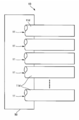
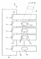
上記の製造方法を具体的に説明すると、図14に示すように、多心ケーブル10を構成する全ての同軸ケーブル11を並列に配置し、同軸ケーブル11の端部の位置を合わせる。そして、これらの同軸ケーブル11を治具50やテープ等(図示省略)で保持する。(保持工程)。
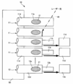
図15に示すように、次に、エキシマレーザ光等のレーザ光40を同軸ケーブル11に順番に照射し、外部導体11cを露出させるように、除去部11eを形成する。(除去部形成工程)。この際、内部絶縁層11bは、変性ポリフェニレンエーテル樹脂又はシクロオレフィンポリマー樹脂であることが好ましい。尚、グランド用とする同軸ケーブル11(グランド用同軸ケーブル12)に対しては、図20にも示すように、レーザ光40を内部導体12aにまで到達させた除去部12eとすることによって、外部導体12cと内部導体12aとを露出させる。これにより、複数の同軸ケーブル11と1以上のグランド用同軸ケーブル12とを形成する(除去部形成工程)。
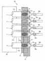
図16に示すように、次に、除去部11e・12eに導電部材21を充填する。例えば、除去部11e・12eに導電性塗料を充填する(充填工程)。この後、図17に示すように、YAGレーザやCO2レーザ、エキシマレーザ等のレーザ光の波長や強度を調整して被覆層11d・12d及び外部導体11c・12c(図20参照)を切断し、端部側を引き抜いて除去する。そして、図18に示すように、レーザ光の波長や強度を調整して内部絶縁層11b・12bを切断し、端部側の内部絶縁層11b・12bを引き抜いて除去する(口出し工程)。
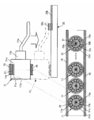
図19及び図20に示すように、同軸ケーブル11及びグランド用同軸ケーブル12をグランド部材15・16により挟み込み、グランド部材15・16を同軸ケーブル11及びグランド用同軸ケーブル12の除去部11e・12eに充填された導電部材21に当接させる。尚、グランド部材15・16は、半田層側が同軸ケーブル11側に対向するように設定されている。そして、グランド部材15・16により挟み込んだ状態を維持しながら加熱し、グランド部材15・16の半田層を溶融させ、同軸ケーブル11及びグランド用同軸ケーブル12の導電部材21とグランド部材15・16とを導電接続させる(半田付け工程)。
この後、図1に示すように、端部が集合一体化された多心ケーブル10が、コネクタ端子や基板(FPC等の)等の被接続部材30に接続される。例えば、基板である被接続部材30に接続する場合は、グランド部材15・16の両端部に位置する端部接地部が半田付けされ、接地用の被接続部30aに電気的に接続される。そして、同軸ケーブル11及びグランド用同軸ケーブル12の内部導体11a・12aが適宜屈曲され、対応するそれぞれの被接続部30bに半田部30cで半田付けされ、内部導体11aと被接続部30bとが電気的に接続される。
また、被接続部材30がコネクタである場合には、一方のグランド部材15の上に金属板のシェルを被せて半田付けする。このシェルをコネクタの接地用の被接続部に接続して、グランド部材15の接地を行う。また、グランド部材15・16の両端部を半田付けして電気的に接続する。これにより、多心ケーブル10がコネクタ付き多心ケーブルの形態とされる。
(多心ケーブルの製造方法:変形例)
本実施形態においては、板状のグランド部材15・16間に同軸ケーブル11及びグランド用同軸ケーブル12を配置した状態にして、グランド部材15・16と同軸ケーブル11及びグランド用同軸ケーブル12の導電部材21とを導電接続させる半田付け工程について説明した。即ち、本実施形態においては、板状のグランド部材15・16を用いた製造方法について説明したが、これに限定されるものではない。
本実施形態においては、板状のグランド部材15・16間に同軸ケーブル11及びグランド用同軸ケーブル12を配置した状態にして、グランド部材15・16と同軸ケーブル11及びグランド用同軸ケーブル12の導電部材21とを導電接続させる半田付け工程について説明した。即ち、本実施形態においては、板状のグランド部材15・16を用いた製造方法について説明したが、これに限定されるものではない。
図21に示すように、具体的に説明すると、多心ケーブル10の製造方法は、内部導体11aと、内部導体11aの外周面を被覆する内部絶縁層11bと、内部絶縁層11bの外周面を被覆する外部導体11cと、外部導体11cの外周面を被覆する被覆層11dとを有した同軸ケーブル11に対して、外部導体11cを露出させるように被覆層11dにおける周方向の一部を除去することにより除去部11eを形成した後、同軸ケーブル11の複数を並列配置した状態で、導電性ペースト60を除去部11eに充填することにより導電部材21を形成すると共に、導電性ペーストによりグランド部材を形成してもよい。
上記の製造方法によれば、板状のグランド部材15・16を用いた場合の効果に加えて、下記の効果を有する。即ち、複数の同軸ケーブル11を並列配置し、これらの同軸ケーブル11の除去部11eに導電性ペーストを充填して導電部材21を形成すると共にグランド部材を形成することによって、板状のグランド部材15・16を用いる場合と比較して、グランド部材の外部導体11cへの接続作業、即ち、導電部材21の除去部11eへの充填と、グランド部材の同軸ケーブル11への接続とを導電性ペースト60により1工程で完了することができるため、作業性の優れたものとなる。
(レーザ光と加工性の関係)
次に、同軸ケーブル11に除去部11eをレーザ光40により形成する場合において、同軸ケーブル11の各部の材質とレーザ光の種類とで加工性の良否に相違があるかについて調査した。この調査結果を下記に説明する。
次に、同軸ケーブル11に除去部11eをレーザ光40により形成する場合において、同軸ケーブル11の各部の材質とレーザ光の種類とで加工性の良否に相違があるかについて調査した。この調査結果を下記に説明する。
調査方法(実験方法)を詳細に説明する。先ず、同軸ケーブル11の各部位に対応する100mm(縦)×100mm(横)の正方形シート状のサンプル片を表1の材料でそれぞれ準備した。具体的に説明すると、内部絶縁層11bに対応するサンプル片として、フッ素樹脂と、ポリ塩化ビニル樹脂(PVC)と、変性ポリフェニレンエーテル樹脂(m-PPE)と、シクロオレフィン樹脂(COP)と、COP(100phr((per hundred resin)))とスチレン・ブタジエン共重合体(10phr)の混合樹脂と、COP(100phr)とスチレン・ブタジエン共重合体(25phr)の混合樹脂と、COP(10phr)とスチレン・ブタジエン共重合体(100phr)の混合樹脂とを、それぞれ50μmの厚みを有した正方形シート状に形成することにより準備した。
外部導体11cに対応するサンプル片として、m-PPEの正方形シート(50μm)にAgペーストを100μmの厚みで塗布することにより準備すると共に、35μmの厚みの銅箔を正方形シート状に形成することにより準備した。被覆層11dに対応するサンプル片として、フッ素樹脂とウレタン樹脂とポリカーボネート樹脂とを、それぞれ50μmの厚みを有した正方形シート状に形成することにより準備した。
以上の各サンプル片について、CO2レーザ光とYAGレーザ光とエキシマレーザ光とをそれぞれ照射したときの加工性を調査した。レーザ光の照射条件は、照射時間が5秒、照射面積が250μm(縦)×250μm(横)の四角とし、全レーザ光において同一とした。ここで、加工性は、レーザ光の照射によりサンプル片が厚み方向に貫通したという評価(○)と、サンプル片が厚み方向に貫通しなかったという評価(△)と、レーザ光に反応しなかったという評価(×)との3段階の評価で区分した。
この結果、表1に示すように、エキシマレーザ光は、m-PPEのサンプル片と、Agペーストのサンプル片と、ウレタン樹脂のサンプル片と、ポリカーボネート樹脂のサンプル片とに対して良好な加工性(評価○)を有していることが判明した。また、エキシマレーザ光は、100%のCOP樹脂には低い加工性(評価×)であるが、COPとスチレン・ブタジエン共重合体の混合樹脂(100:10、100:25、10:100)のサンプル片に対しては良好な加工性(評価○)を有することが判明した。
これにより、m-PPE又はCOPとスチレン・ブタジエン共重合体の混合樹脂の内部絶縁層11bと、Agペーストの外部導体11cと、ウレタン樹脂又はポリカーボネート樹脂の被覆層11dとで同軸ケーブル11を構成し、この同軸ケーブル11に対してエキシマレーザ光で加工を行った場合は、除去部11eを良好に形成できることが判明した。

以上の詳細な説明では、本発明をより容易に理解できるように、特徴的部分を中心に説明したが、本発明は、以上の詳細な説明に記載する実施形態に限定されず、その他の実施形態にも適用することができ、その適用範囲は可能な限り広く解釈されるべきである。
また、本明細書において用いた用語及び語法は、本発明を的確に説明するために用いたものであり、本発明の解釈を制限するために用いたものではない。また、当業者であれば、本明細書に記載された発明の概念から、本発明の概念に含まれる他の構成、システム、方法等を推考することは容易であると思われる。従って、請求の範囲の記載は、本発明の技術的思想を逸脱しない範囲で均等な構成を含むものであるとみなされるべきである。また、本発明の目的及び本発明の効果を充分に理解するために、すでに開示されている文献等を充分に参酌することが望まれる。
本国際出願は、2016年3月30日に出願された日本国特許出願である特願2016-069049号に基づく優先権を主張するものであり、当該日本国特許出願である特願2016-069049号の全内容は、本国際出願に援用される。
本発明の特定の実施の形態についての上記説明は、例示を目的として提示したものである。それらは、網羅的であったり、記載した形態そのままに本発明を制限したりすることを意図したものではない。数多くの変形や変更が、上記の記載内容に照らして可能であることは当業者に自明である。
10 多心ケーブル
11 同軸ケーブル
11a 内部導体
11b 内部絶縁層
11c 外部導体
11d 被覆層
11e 除去部
12 グランド用同軸ケーブル
12a 内部導体
12b 内部絶縁層
12c 外部導体
12d 被覆層
12e 除去部
15 グランド部材
16 グランド部材
21 導電部材
40 レーザ光
60 導電性ペースト
11 同軸ケーブル
11a 内部導体
11b 内部絶縁層
11c 外部導体
11d 被覆層
11e 除去部
12 グランド用同軸ケーブル
12a 内部導体
12b 内部絶縁層
12c 外部導体
12d 被覆層
12e 除去部
15 グランド部材
16 グランド部材
21 導電部材
40 レーザ光
60 導電性ペースト
Claims (9)
- 並列配置された複数の同軸ケーブルと、これら同軸ケーブルに導電接続されたグランド部材とを備えた多心ケーブルであって、
前記同軸ケーブルは、
内部導体と、前記内部導体の外周面を被覆する内部絶縁層と、前記内部絶縁層の外周面を被覆する外部導体と、前記外部導体の外周面を被覆する被覆層と、前記外部導体を露出させるように前記被覆層における周方向の一部が除去された除去部と、前記除去部に充填された導電部材とを有しており、
前記グランド部材は、
前記除去部に充填された前記導電部材に導電接続されていることを特徴とする多心ケーブル。 - 前記除去部は、穴形状に形成されていることを特徴とする請求項1に記載の多心ケーブル。
- 前記除去部は、前記被覆層の外周面側を最大径とする錐台形状に形成されていることを特徴とする請求項2に記載の多心ケーブル。
- 前記同軸ケーブルの少なくとも一つは、
前記除去部が、さらに前記内部導体を露出させていることを特徴とする請求項1乃至3の何れか1項に記載の多心ケーブル。 - 前記グランド部材と前記導電部材とは、導電性ペーストにより形成されていることを特徴とする請求項1乃至4の何れか1項に記載の多心ケーブル。
- 前記同軸ケーブルにおける前記内部絶縁層が、変性ポリフェニレンエーテル、又はシクロオレフィン樹脂とスチレン・ブタジエン共重合体との混合樹脂であることを特徴とする請求項4に記載の多心ケーブル。
- 並列配置された複数の同軸ケーブルと、これら同軸ケーブルに導電接続されたグランド部材とを備えた多心ケーブルの製造方法であって、
内部導体と、前記内部導体の外周面を被覆する内部絶縁層と、前記内部絶縁層の外周面を被覆する外部導体と、前記外部導体の外周面を被覆する被覆層とを有した同軸ケーブルに対して、前記外部導体を露出させるように前記被覆層における周方向の一部を除去することにより除去部を形成した後、前記除去部に導電部材を充填し、
前記同軸ケーブルの複数を並列配置した状態で、前記除去部に充填された前記導電部材に前記グランド部材を導電接続させることを特徴とする多心ケーブルの製造方法。 - 前記除去部が、レーザ光により形成されることを特徴とする請求項7に記載の多心ケーブルの製造方法。
- 並列配置された複数の同軸ケーブルと、これら同軸ケーブルに導電接続されたグランド部材とを備えた多心ケーブルの製造方法であって、
内部導体と、前記内部導体の外周面を被覆する内部絶縁層と、前記内部絶縁層の外周面
を被覆する外部導体と、前記外部導体の外周面を被覆する被覆層とを有した同軸ケーブルに対して、前記外部導体を露出させるように前記被覆層における周方向の一部を除去することにより除去部を形成した後、
前記同軸ケーブルの複数を並列配置した状態で、導電性ペーストを前記除去部に充填することにより導電部材を形成すると共に、前記導電性ペーストにより前記グランド部材を形成することを特徴とする多心ケーブルの製造方法。
Priority Applications (2)
| Application Number | Priority Date | Filing Date | Title |
|---|---|---|---|
| US16/089,192 US10403418B2 (en) | 2016-03-30 | 2017-02-21 | Multicore cable and method for manufacturing multicore cable |
| CN201780021018.1A CN108885923B (zh) | 2016-03-30 | 2017-02-21 | 多芯缆线及多芯缆线的制造方法 |
Applications Claiming Priority (2)
| Application Number | Priority Date | Filing Date | Title |
|---|---|---|---|
| JP2016-069049 | 2016-03-30 | ||
| JP2016069049A JP6620054B2 (ja) | 2016-03-30 | 2016-03-30 | 多心ケーブル及び多心ケーブルの製造方法 |
Publications (1)
| Publication Number | Publication Date |
|---|---|
| WO2017169294A1 true WO2017169294A1 (ja) | 2017-10-05 |
Family
ID=59963050
Family Applications (1)
| Application Number | Title | Priority Date | Filing Date |
|---|---|---|---|
| PCT/JP2017/006280 Ceased WO2017169294A1 (ja) | 2016-03-30 | 2017-02-21 | 多心ケーブル及び多心ケーブルの製造方法 |
Country Status (5)
| Country | Link |
|---|---|
| US (1) | US10403418B2 (ja) |
| JP (1) | JP6620054B2 (ja) |
| CN (1) | CN108885923B (ja) |
| TW (1) | TWI711057B (ja) |
| WO (1) | WO2017169294A1 (ja) |
Families Citing this family (9)
| Publication number | Priority date | Publication date | Assignee | Title |
|---|---|---|---|---|
| EP3780014A4 (en) * | 2018-03-30 | 2021-12-29 | Furukawa Electric Co., Ltd. | Insulated electric wire material, method for manufacturing insulated electric wire material, coil, and electric/electronic device |
| CN109494006A (zh) * | 2018-10-12 | 2019-03-19 | 苏州新亚电通有限公司 | 一种镀金反折Pin柔性扁平电缆 |
| JP7118905B2 (ja) * | 2019-01-25 | 2022-08-16 | 東京製綱株式会社 | ドリル、被覆付きケーブルの検査方法及び被覆付きケーブルの被覆サンプリング方法 |
| JP7021648B2 (ja) * | 2019-02-14 | 2022-02-17 | 日立金属株式会社 | グランドバー付はんだ及び同軸ケーブルアレイ製造方法 |
| JP7701783B2 (ja) * | 2020-04-23 | 2025-07-02 | 株式会社Totoku | 同軸フラットケーブル |
| US11153970B1 (en) | 2020-07-20 | 2021-10-19 | Atl Technology, Llc | Apparatus with electrical components end mounted to printed circuit board |
| US11735879B2 (en) | 2021-03-09 | 2023-08-22 | Atl Technology, Llc | Adaptor for converting a ball grid array interface into a pin interface |
| US12177989B2 (en) | 2021-11-16 | 2024-12-24 | Atl Technology, Llc | Direct wire attachment methods and apparatus for a BGA component |
| CN119274873A (zh) * | 2023-07-07 | 2025-01-07 | 春源科技(深圳)有限公司 | 软性排线 |
Citations (2)
| Publication number | Priority date | Publication date | Assignee | Title |
|---|---|---|---|---|
| WO2009014010A1 (ja) * | 2007-07-25 | 2009-01-29 | Phoeton Corporation | ワイヤーハーネス |
| JP2015138752A (ja) * | 2014-01-24 | 2015-07-30 | 日立金属株式会社 | ハロゲンフリー同軸ケーブル並びにこれを用いたフラットケーブル及びケーブルハーネス |
Family Cites Families (15)
| Publication number | Priority date | Publication date | Assignee | Title |
|---|---|---|---|---|
| US5241135A (en) * | 1991-12-13 | 1993-08-31 | The Boeing Company | Connector grounding terminal |
| US5281762A (en) * | 1992-06-19 | 1994-01-25 | The Whitaker Corporation | Multi-conductor cable grounding connection and method therefor |
| US6326548B1 (en) * | 1999-07-09 | 2001-12-04 | Nissei Electric Co., Ltd. | End-processed coaxial cable structures and methods for producing the same |
| DE10004887A1 (de) * | 2000-02-04 | 2001-08-23 | Daume Karin Maschinenteile | Einrichtung zum Kontaktieren von insbesondere länglichen, bspw. im wesentlichen zylindrischen Körpern, bspw. Rohren oder Kabeln |
| US6486402B2 (en) * | 2001-04-18 | 2002-11-26 | Harger, Inc. | Cable grounding clamp |
| JP4143280B2 (ja) * | 2001-06-01 | 2008-09-03 | 日本電気株式会社 | 実装構造体、該実装構造体の製造方法、印刷用マスク、および印刷方法 |
| US6734374B2 (en) * | 2002-05-30 | 2004-05-11 | Hon Hai Precision Ind. Co., Ltd. | Micro-coaxial cable assembly and method for making the same |
| US6953897B2 (en) * | 2003-08-21 | 2005-10-11 | International Business Machines Corporation | Device and method for clamping and grounding a cable |
| JP4133980B2 (ja) * | 2004-09-09 | 2008-08-13 | ケル株式会社 | フラットケーブル |
| JP2007280772A (ja) | 2006-04-06 | 2007-10-25 | Sumitomo Electric Ind Ltd | 多心ケーブル、コネクタ付き多心ケーブル、及びそれらの製造方法 |
| JP5163865B2 (ja) * | 2007-11-14 | 2013-03-13 | 日立電線株式会社 | 多芯ケーブルアセンブリ及びその製造方法 |
| JP5817674B2 (ja) * | 2011-09-16 | 2015-11-18 | 日立金属株式会社 | ノンドレイン差動信号伝送用ケーブル及びそのグランド接続構造 |
| TW201401300A (zh) * | 2012-06-26 | 2014-01-01 | Sumitomo Electric Industries | 多芯纜線 |
| KR20160010469A (ko) * | 2013-04-24 | 2016-01-27 | 가부시키가이샤 쇼난 고세이쥬시 세이사쿠쇼 | 신호 전송용 플랫 케이블 |
| JP6056649B2 (ja) * | 2013-05-15 | 2017-01-11 | 日立金属株式会社 | 高速伝送線の終端構造、終端方法および終端端子 |
-
2016
- 2016-03-30 JP JP2016069049A patent/JP6620054B2/ja active Active
- 2016-12-07 TW TW105140320A patent/TWI711057B/zh active
-
2017
- 2017-02-21 CN CN201780021018.1A patent/CN108885923B/zh active Active
- 2017-02-21 US US16/089,192 patent/US10403418B2/en active Active
- 2017-02-21 WO PCT/JP2017/006280 patent/WO2017169294A1/ja not_active Ceased
Patent Citations (2)
| Publication number | Priority date | Publication date | Assignee | Title |
|---|---|---|---|---|
| WO2009014010A1 (ja) * | 2007-07-25 | 2009-01-29 | Phoeton Corporation | ワイヤーハーネス |
| JP2015138752A (ja) * | 2014-01-24 | 2015-07-30 | 日立金属株式会社 | ハロゲンフリー同軸ケーブル並びにこれを用いたフラットケーブル及びケーブルハーネス |
Also Published As
| Publication number | Publication date |
|---|---|
| US10403418B2 (en) | 2019-09-03 |
| CN108885923B (zh) | 2021-04-09 |
| JP2017183098A (ja) | 2017-10-05 |
| US20190115124A1 (en) | 2019-04-18 |
| CN108885923A (zh) | 2018-11-23 |
| TW201735059A (zh) | 2017-10-01 |
| JP6620054B2 (ja) | 2019-12-11 |
| TWI711057B (zh) | 2020-11-21 |
Similar Documents
| Publication | Publication Date | Title |
|---|---|---|
| JP6620054B2 (ja) | 多心ケーブル及び多心ケーブルの製造方法 | |
| CN101542640B (zh) | 线束 | |
| JP5141105B2 (ja) | 多心ケーブルハーネス及びコネクタ付き多心ケーブルハーネス | |
| JP2010146939A (ja) | フラットケーブルの半田接続方法 | |
| JP4910721B2 (ja) | 多心ケーブル、コネクタ付き多心ケーブル及び多心ケーブルの接続構造 | |
| WO2009139041A1 (ja) | ケーブルハーネス、コネクタ付きケーブルハーネス及びケーブルハーネスの接続構造 | |
| TW200937782A (en) | Connection structure and connection method of coaxial cable harness | |
| CN101483283A (zh) | 同轴电缆束的连接构造 | |
| WO2015123864A1 (en) | Wiring member and manufacturing method thereof | |
| JP2007280772A (ja) | 多心ケーブル、コネクタ付き多心ケーブル、及びそれらの製造方法 | |
| JP2008210563A (ja) | 多心同軸ケーブルおよび多心同軸ケーブルの製造方法 | |
| JP2014089902A (ja) | ケーブル接続体およびケーブル接続方法 | |
| JP4492773B2 (ja) | 多心同軸電線の接続端末とその製造方法 | |
| JP2005050622A (ja) | 端末加工ケーブル及びその製造方法 | |
| JP2006185741A (ja) | 端末加工同軸ケーブル及びその製造方法 | |
| JP2008112699A (ja) | 極細同軸線ハーネス、極細同軸線ハーネス接続体、および極細同軸線ハーネスの接続方法 | |
| JP2017022022A (ja) | 差動信号伝送用ケーブル及びコネクタ付きケーブル | |
| EP4568037A1 (en) | Multi-core cable, method for manufacturing same, and electronic equipment using same | |
| EP2648299B1 (en) | Terminal structure for coaxial cable and connection structure for terminal of the coaxial cable | |
| JP2012134048A (ja) | 同軸ケーブルハーネス及びその製造方法 | |
| CN107534229A (zh) | 带连接器的多芯线缆及其制造方法 | |
| JP5284836B2 (ja) | 同軸ケーブルの端末構造 | |
| JP2010073945A (ja) | 電線の接続方法及びそれに用いる電極の支持体 | |
| JPH11297133A (ja) | 電線加工品及びその製造方法 | |
| JP2011076908A (ja) | 同軸ケーブルの接続構造及びその接続方法 |
Legal Events
| Date | Code | Title | Description |
|---|---|---|---|
| NENP | Non-entry into the national phase |
Ref country code: DE |
|
| 121 | Ep: the epo has been informed by wipo that ep was designated in this application |
Ref document number: 17773842 Country of ref document: EP Kind code of ref document: A1 |
|
| 122 | Ep: pct application non-entry in european phase |
Ref document number: 17773842 Country of ref document: EP Kind code of ref document: A1 |