WO2017169155A1 - 基板液処理装置及び基板液処理方法並びに基板液処理プログラムを記憶したコンピュータ読み取り可能な記憶媒体 - Google Patents
基板液処理装置及び基板液処理方法並びに基板液処理プログラムを記憶したコンピュータ読み取り可能な記憶媒体 Download PDFInfo
- Publication number
- WO2017169155A1 WO2017169155A1 PCT/JP2017/004681 JP2017004681W WO2017169155A1 WO 2017169155 A1 WO2017169155 A1 WO 2017169155A1 JP 2017004681 W JP2017004681 W JP 2017004681W WO 2017169155 A1 WO2017169155 A1 WO 2017169155A1
- Authority
- WO
- WIPO (PCT)
- Prior art keywords
- substrate
- etching
- processing
- film
- temperature
- Prior art date
- Legal status (The legal status is an assumption and is not a legal conclusion. Google has not performed a legal analysis and makes no representation as to the accuracy of the status listed.)
- Ceased
Links
Images




Classifications
-
- H—ELECTRICITY
- H10—SEMICONDUCTOR DEVICES; ELECTRIC SOLID-STATE DEVICES NOT OTHERWISE PROVIDED FOR
- H10P—GENERIC PROCESSES OR APPARATUS FOR THE MANUFACTURE OR TREATMENT OF DEVICES COVERED BY CLASS H10
- H10P50/00—Etching of wafers, substrates or parts of devices
- H10P50/60—Wet etching
- H10P50/66—Wet etching of conductive or resistive materials
- H10P50/663—Wet etching of conductive or resistive materials by chemical means only
- H10P50/667—Wet etching of conductive or resistive materials by chemical means only by liquid etching only
-
- H—ELECTRICITY
- H10—SEMICONDUCTOR DEVICES; ELECTRIC SOLID-STATE DEVICES NOT OTHERWISE PROVIDED FOR
- H10P—GENERIC PROCESSES OR APPARATUS FOR THE MANUFACTURE OR TREATMENT OF DEVICES COVERED BY CLASS H10
- H10P50/00—Etching of wafers, substrates or parts of devices
-
- H—ELECTRICITY
- H10—SEMICONDUCTOR DEVICES; ELECTRIC SOLID-STATE DEVICES NOT OTHERWISE PROVIDED FOR
- H10P—GENERIC PROCESSES OR APPARATUS FOR THE MANUFACTURE OR TREATMENT OF DEVICES COVERED BY CLASS H10
- H10P50/00—Etching of wafers, substrates or parts of devices
- H10P50/20—Dry etching; Plasma etching; Reactive-ion etching
- H10P50/28—Dry etching; Plasma etching; Reactive-ion etching of insulating materials
- H10P50/282—Dry etching; Plasma etching; Reactive-ion etching of insulating materials of inorganic materials
-
- H—ELECTRICITY
- H10—SEMICONDUCTOR DEVICES; ELECTRIC SOLID-STATE DEVICES NOT OTHERWISE PROVIDED FOR
- H10P—GENERIC PROCESSES OR APPARATUS FOR THE MANUFACTURE OR TREATMENT OF DEVICES COVERED BY CLASS H10
- H10P50/00—Etching of wafers, substrates or parts of devices
- H10P50/60—Wet etching
- H10P50/64—Wet etching of semiconductor materials
- H10P50/642—Chemical etching
-
- H—ELECTRICITY
- H10—SEMICONDUCTOR DEVICES; ELECTRIC SOLID-STATE DEVICES NOT OTHERWISE PROVIDED FOR
- H10P—GENERIC PROCESSES OR APPARATUS FOR THE MANUFACTURE OR TREATMENT OF DEVICES COVERED BY CLASS H10
- H10P72/00—Handling or holding of wafers, substrates or devices during manufacture or treatment thereof
- H10P72/04—Apparatus for manufacture or treatment
- H10P72/0402—Apparatus for fluid treatment
- H10P72/0418—Apparatus for fluid treatment for etching
- H10P72/0422—Apparatus for fluid treatment for etching for wet etching
-
- H—ELECTRICITY
- H10—SEMICONDUCTOR DEVICES; ELECTRIC SOLID-STATE DEVICES NOT OTHERWISE PROVIDED FOR
- H10P—GENERIC PROCESSES OR APPARATUS FOR THE MANUFACTURE OR TREATMENT OF DEVICES COVERED BY CLASS H10
- H10P72/00—Handling or holding of wafers, substrates or devices during manufacture or treatment thereof
- H10P72/04—Apparatus for manufacture or treatment
- H10P72/0402—Apparatus for fluid treatment
- H10P72/0418—Apparatus for fluid treatment for etching
- H10P72/0422—Apparatus for fluid treatment for etching for wet etching
- H10P72/0426—Apparatus for fluid treatment for etching for wet etching with the semiconductor substrates being dipped in baths or vessels
-
- H—ELECTRICITY
- H10—SEMICONDUCTOR DEVICES; ELECTRIC SOLID-STATE DEVICES NOT OTHERWISE PROVIDED FOR
- H10P—GENERIC PROCESSES OR APPARATUS FOR THE MANUFACTURE OR TREATMENT OF DEVICES COVERED BY CLASS H10
- H10P72/00—Handling or holding of wafers, substrates or devices during manufacture or treatment thereof
- H10P72/06—Apparatus for monitoring, sorting, marking, testing or measuring
- H10P72/0602—Temperature monitoring
-
- H—ELECTRICITY
- H10—SEMICONDUCTOR DEVICES; ELECTRIC SOLID-STATE DEVICES NOT OTHERWISE PROVIDED FOR
- H10P—GENERIC PROCESSES OR APPARATUS FOR THE MANUFACTURE OR TREATMENT OF DEVICES COVERED BY CLASS H10
- H10P95/00—Generic processes or apparatus for manufacture or treatments not covered by the other groups of this subclass
- H10P95/04—Planarisation of conductive or resistive materials
-
- H—ELECTRICITY
- H10—SEMICONDUCTOR DEVICES; ELECTRIC SOLID-STATE DEVICES NOT OTHERWISE PROVIDED FOR
- H10W—GENERIC PACKAGES, INTERCONNECTIONS, CONNECTORS OR OTHER CONSTRUCTIONAL DETAILS OF DEVICES COVERED BY CLASS H10
- H10W20/00—Interconnections in chips, wafers or substrates
- H10W20/01—Manufacture or treatment
- H10W20/031—Manufacture or treatment of conductive parts of the interconnections
- H10W20/062—Manufacture or treatment of conductive parts of the interconnections by smoothing of conductive parts, e.g. by planarisation
Definitions
- the present invention relates to a substrate liquid processing apparatus and a substrate liquid processing method for liquid processing a substrate using a processing liquid, and a computer-readable storage medium storing a substrate liquid processing program.
- a substrate liquid processing apparatus is used to perform processing such as etching using a processing liquid such as an etching liquid on a substrate such as a semiconductor wafer or a liquid crystal substrate.
- contact holes are formed in an insulating film on a substrate surface, and a film (for example, a metal layer such as tungsten) is deposited on the insulating film inside and outside the recesses, and then etched.
- a technique is known in which a liquid (for example, an etching solution mixed with phosphoric acid, nitric acid, acetic acid, etc.) is etched at a temperature (70 ° C. or higher) at which the etching rate of the metal layer is high (Patent Document 1). ).
- the metal layer in the recess is prevented from being etched as much as possible, and the remaining film of the metal layer outside the recess is made as thin as possible, or the liquid treatment is performed in a short time so that the metal layer does not remain outside the recess. It is desirable.
- the metal layer can be removed in a short time when treated with an etching solution having a high etching rate, but the metal layer in the recess may also be etched.
- the first etching rate is set.
- the etching solution is set to a first temperature so that the coating film outside the recess is removed in a first processing time, and then a second lower than the first etching rate in a second processing time.
- the etching solution is set to a second temperature so as to achieve an etching rate, and the second coating removal step of removing the coating outside the recess while leaving the coating inside the recess in a second processing time is provided. .
- the substrate liquid processing apparatus for performing the etching process by bringing the etching solution for removing the coating into contact with the surface of the substrate on which the coating covering the inside of the recess and the outside of the recess is formed, the outside of the recess is covered.
- the substrate includes an etching solution supply unit that supplies the etching solution to the surface of the substrate, and a control unit that controls the etching solution supply unit. Supply the etching solution so that the temperature of the etching solution supplied from the solution supply unit to the surface of the substrate is set to a first temperature so as to be the first etching rate, and the coating outside the recess is removed in a first processing time.
- the film inside the recess of the substrate is left, and the film outside the recess can be etched with high accuracy.
- Plane explanatory drawing which shows a substrate liquid processing apparatus.
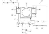
- Explanatory drawing which shows an etching processing apparatus.
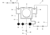
- Explanatory drawing which shows the operation
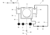
- Explanatory drawing which shows the operation
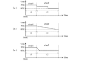
- Explanatory drawing which shows the change of time and temperature at the time of an etching process.
- Explanatory drawing which shows the change of the time and temperature in another form at the time of an etching process Explanatory drawing which shows another form of an etching processing apparatus.
- the substrate liquid processing apparatus 1 includes a carrier carry-in / out unit 2, a lot forming unit 3, a lot placement unit 4, a lot transport unit 5, a lot processing unit 6, and a control unit 7.
- the carrier loading / unloading unit 2 loads and unloads a carrier 9 in which a plurality of (for example, 25) substrates (silicon wafers) 8 are stored in a horizontal posture.
- the carrier loading / unloading unit 2 includes a carrier stage 10 on which a plurality of carriers 9 are placed, a carrier transport mechanism 11 that transports the carriers 9, carrier carriers 12, 13 that temporarily store the carriers 9, A carrier mounting table 14 on which the carrier 9 is mounted is provided.
- the carrier stock 12 is temporarily stored before the substrate 8 as a product is processed by the lot processing unit 6.
- the carrier stock 13 is temporarily stored after the substrate 8 to be a product is processed by the lot processing unit 6.
- the carrier loading / unloading unit 2 transports the carrier 9 loaded from the outside to the carrier stage 10 to the carrier stock 12 and the carrier mounting table 14 using the carrier transport mechanism 11.
- the carrier loading / unloading unit 2 transports the carrier 9 placed on the carrier placing table 14 to the carrier stock 13 and the carrier stage 10 using the carrier carrying mechanism 11.
- the carrier 9 conveyed to the carrier stage 10 is carried out to the outside.
- the lot forming unit 3 forms a lot composed of a plurality of (for example, 50) substrates 8 to be processed simultaneously by combining the substrates 8 accommodated in one or a plurality of carriers 9.
- the lot forming unit 3 is provided with a substrate transfer mechanism 15 for transferring a plurality of substrates 8.
- the substrate transport mechanism 15 can change the posture of the substrate 8 from the horizontal posture to the vertical posture and from the vertical posture to the horizontal posture during the transportation of the substrate 8.
- the lot forming unit 3 transfers the substrate 8 from the carrier 9 mounted on the carrier mounting table 14 to the lot mounting unit 4 by using the substrate transfer mechanism 15, and the substrate 8 for forming the lot is transferred to the lot mounting unit.
- the lot forming unit 3 mounted on 4 transports the lot mounted on the lot mounting unit 4 to the carrier 9 mounted on the carrier mounting table 14 by the substrate transport mechanism 15.
- the substrate transport mechanism 15 is a substrate support unit for supporting a plurality of substrates 8, a pre-process substrate support unit that supports the substrate 8 before processing (before being transported by the lot transport unit 5), and a process There are two types of post-process substrate support units that support the subsequent substrate 8 (after being transported by the lot transport unit 5). This prevents particles or the like adhering to the substrate 8 before processing from being transferred to the substrate 8 after processing.
- the lot placement unit 4 temporarily places (waits) the lot transported between the lot formation unit 3 and the lot processing unit 6 by the lot transportation unit 5 on the lot placement table 16.
- the lot placement unit 4 includes a loading-side lot placement table 17 for placing a lot before processing (before being transported by the lot transport unit 5), and after processing (after transported by the lot transport unit 5).
- a carry-out lot mounting table 18 on which the lot is mounted is provided.
- the lot placement unit 4 the lot formed by the lot formation unit 3 is placed on the carry-in lot placement table 17, and the lot is carried into the lot processing unit 6 via the lot transport unit 5.
- the lot carried out from the lot processing unit 6 via the lot transport unit 5 is placed on the carry-out side lot placement table 18, and the lot is transported to the lot forming unit 3.
- the lot conveyance unit 5 conveys a lot between the lot placement unit 4 and the lot processing unit 6 or between the lot processing unit 6.
- the lot transport unit 5 is provided with a lot transport mechanism 19 for transporting lots.
- the lot transport mechanism 19 includes a rail 20 disposed along the lot placement unit 4 and the lot processing unit 6, and a moving body 21 that moves along the rail 20 while holding a plurality of substrates 8.
- the moving body 21 is provided with a substrate holding body 22 for holding a plurality of substrates 8 arranged in the front-rear direction in a vertical posture so as to freely advance and retract.
- the lot transport unit 5 receives the lot placed on the carry-in side lot placing table 17 by the substrate holder 22 of the lot transport mechanism 19 and delivers the lot to the lot processing unit 6.
- the lot transfer unit 5 receives the lot processed by the lot processing unit 6 by the substrate holder 22 of the lot transfer mechanism 19 and transfers the lot to the unloading lot mounting table 18. Further, the lot transfer unit 5 uses the lot transfer mechanism 19 to transfer the lot within the lot processing unit 6.
- the lot processing unit 6 performs processing such as etching, cleaning, and drying by using a plurality of substrates 8 arranged in a vertical posture at the front and back as one lot.
- the lot processing unit 6 includes a drying processing device 23 for drying the substrate 8, a substrate holder cleaning processing device 24 for cleaning the substrate holder 22, and a cleaning processing device 25 for cleaning the substrate 8. And two etching apparatuses 26 for performing the etching process of the substrate 8 are provided side by side.
- the drying processing apparatus 23 is provided with a substrate elevating mechanism 28 in a processing tank 27 so as to be movable up and down.
- the processing tank 27 is supplied with a processing gas for drying (IPA (isopropyl alcohol) or the like).
- the substrate lifting mechanism 28 holds a plurality of substrates 8 for one lot side by side in a vertical posture.
- the drying processing device 23 receives the lot from the substrate holder 22 of the lot transport mechanism 19 by the substrate lifting mechanism 28, and lifts and lowers the lot by the substrate lifting mechanism 28, thereby using the drying processing gas supplied to the processing tank 27.
- the substrate 8 is dried. Further, the drying processing apparatus 23 delivers the lot from the substrate lifting mechanism 28 to the substrate holder 22 of the lot transport mechanism 19.
- the substrate holder cleaning processing device 24 is configured to be able to supply a cleaning processing liquid and a dry gas to the processing tank 29, and after supplying the cleaning processing liquid to the substrate holder 22 of the lot transport mechanism 19, The substrate holder 22 is cleaned by supplying the dry gas.
- the cleaning apparatus 25 includes a cleaning processing tank 30 and a rinsing processing tank 31, and substrate lifting mechanisms 32 and 33 are provided in the processing tanks 30 and 31 so as to be movable up and down.
- a cleaning processing solution (SC-1 or the like) is stored in the cleaning processing tank 30.
- the rinsing treatment tank 31 stores a rinsing treatment liquid (pure water or the like).
- the etching processing apparatus 26 includes a processing tank 34 for etching and a processing tank 35 for rinsing, and substrate lifting mechanisms 36 and 37 are provided in the processing tanks 34 and 35 so as to be movable up and down.
- the etching processing bath 34 stores an etching processing solution.
- the rinsing treatment tank 35 stores a rinsing treatment liquid (pure water or the like).
- the cleaning processing device 25 and the etching processing device 26 have the same configuration.
- the etching processing apparatus 26 will be described.
- the substrate elevating mechanisms 36 and 37 hold a plurality of substrates 8 for one lot side by side in a vertical posture.
- the etching processing apparatus 26 receives the lot from the substrate holder 22 of the lot transport mechanism 19 by the substrate lifting mechanism 36, and the substrate lifting mechanism 36 moves the lot up and down so that the lot is immersed in the etching processing liquid in the processing tank 34. Then, the substrate 8 is etched. Thereafter, the etching processing apparatus 26 delivers the lot from the substrate lifting mechanism 36 to the substrate holder 22 of the lot transport mechanism 19.
- the etching processing device 26 receives the lot from the substrate holder 22 of the lot transport mechanism 19 by the substrate lifting mechanism 37, and lifts the lot by the substrate lifting mechanism 37, thereby processing the lot into the processing liquid for rinsing the processing tank 35. Then, the substrate 8 is rinsed. Thereafter, the etching processing apparatus 26 delivers the lot from the substrate lifting mechanism 37 to the substrate holder 22 of the lot transport mechanism 19.
- the control unit 7 controls the operation of each unit of the substrate liquid processing apparatus 1 (such as the carrier carry-in / out unit 2, the lot forming unit 3, the lot placing unit 4, the lot transport unit 5, and the lot processing unit 6).
- the control unit 7 is a computer, for example, and includes a computer-readable storage medium 58.
- the storage medium 58 stores a program for controlling various processes executed in the substrate liquid processing apparatus 1.
- the control unit 7 controls the operation of the substrate liquid processing apparatus 1 by reading and executing a program stored in the storage medium 58.
- the program may be stored in a computer-readable storage medium 58 and installed in the storage medium 58 of the control unit 7 from another storage medium.
- Examples of the computer-readable storage medium 58 include a hard disk (HD), a flexible disk (FD), a compact disk (CD), a magnetic optical disk (MO), and a memory card.
- the substrate 8 is subjected to liquid processing (etching processing) using a processing liquid (etching liquid) in which various chemicals having predetermined concentrations and pure water are mixed.
- etching processing liquid processing
- etching liquid processing liquid
- the etching processing device 26 stores a processing liquid and liquid-processes the substrate 8, and an etching-liquid supply unit 39 supplies the processing liquid to the liquid-processing part 38. And a processing liquid discharge section 40 for discharging the processing liquid from the liquid processing section 38.
- the etching solution supply unit 39 includes a chemical solution supply unit 41 for supplying a processing solution to the solution processing unit 38, and a processing solution circulation unit 43 for circulating the processing solution stored in the solution processing unit 38.
- the liquid processing unit 38 forms an outer tank 44 whose upper part is opened around the upper part of the processing tank 34 whose upper part is opened, and stores the processing liquid in the processing tank 34 and the outer tank 44.
- a processing liquid to be liquid processed is stored by immersing the substrate 8 by the substrate lifting mechanism 36.
- the outer tank 44 the processing liquid overflowed from the processing tank 34 is stored, and the processing liquid is supplied to the processing tank 34 by the processing liquid circulation unit 43.
- the chemical liquid supply unit 41 supplies the processing liquid to the liquid processing unit 38.
- the chemical liquid supply unit 41 connects a processing liquid supply source 45 for supplying a processing liquid to an outer tank 44 of the liquid processing unit 38 via a flow rate regulator 46.
- the flow rate regulator 46 is connected to the control unit 7, and the control unit 7 performs open / close control and flow rate control.
- the treatment liquid circulation unit 43 forms a circulation channel 49 between the bottom of the outer tank 44 of the liquid treatment unit 38 and the bottom of the treatment tank 34.
- a pump 50, a filter 51, and a heater 52 are provided in this order.
- the pump 50 and the heater 52 are connected to the control unit 7 and are driven and controlled by the control unit 7.
- the processing liquid circulation unit 43 circulates the processing liquid from the outer tank 44 to the processing tank 34 by driving the pump 50. At that time, the treatment liquid is heated by the heater 52.
- the treatment liquid circulation unit 43 forms a concentration measurement channel 53 between the circulation channel 49 (on the downstream side of the heater 52) and the outer tank 44.
- the concentration measurement channel 53 is provided with an open / close valve 54 and a concentration sensor 55 in this order.
- the on-off valve 54 is connected to the control unit 7 and is controlled to open and close by the control unit 7.
- the concentration sensor 55 is connected to the control unit 7, measures the concentration of the processing liquid flowing through the concentration measurement flow channel 53 in accordance with an instruction from the control unit 7, and notifies the control unit 7 of the measured concentration.
- the treatment liquid discharge unit 40 is connected to a drainage flow path 56 communicating with an external drainage pipe at the bottom of the treatment tank 34 of the liquid treatment part 38, and an open / close valve 57 is provided in the drainage flow path 56.
- the on-off valve 57 is connected to the control unit 7 and is controlled to be opened and closed by the control unit 7.
- the substrate liquid processing apparatus 1 is configured as described above, and in accordance with the substrate liquid processing program stored in the storage medium 58 and the like, the control unit 7 controls each unit (carrier loading / unloading unit 2, lot forming unit 3, lot loading).
- the substrate 8 is processed by controlling the operation of the placement unit 4, the lot transfer unit 5, the lot processing unit 6, and the like.
- a processing liquid is generated by heating the processing liquid of the liquid processing section 38 of the etching processing apparatus 26 to a predetermined temperature by the etching liquid supply section 39.
- the control unit 7 drives the pump 50 to circulate the treatment liquid in the circulation flow path 49 and drives the heater 52 to bring the temperature of the treatment liquid to a predetermined temperature. Let it be maintained. Then, the substrate 8 is immersed in the processing tank 34 in which the processing liquid having a predetermined concentration and a predetermined temperature is stored by the substrate lifting mechanism 36, whereby the substrate 8 is etched (liquid processing) with the processing liquid.
- the control unit 7 measures the concentration of the processing liquid with the concentration sensor 55 at a predetermined timing. At that time, as shown in FIG. 4, the pump 50 is driven to circulate the processing liquid in the circulation flow path 49 as in the liquid processing, and the heater 52 is driven to set the temperature of the processing liquid to a predetermined temperature. To maintain. Further, with the open / close valve 54 opened, a part of the processing liquid flowing through the circulation channel 49 is caused to flow into the concentration measurement channel 53, and the concentration of the processing solution is measured by the concentration sensor 55. After the concentration measurement, the on-off valve 54 is returned to the closed state, and all the processing liquid is circulated through the circulation channel 49.
- a processing liquid heated to a high etching rate for example, 70 ° C.
- a high etching rate for example, 70 ° C.
- the substrate 8 on which the metal layer 62 (for example, tungsten) covering the inside of the recess 61 and the outside of the recess 61 formed in the insulating film 60 for example, silicon oxide film
- the metal layer 62 in the recess 61 is prevented from being etched as much as possible, and the remaining film of the metal layer 62 outside the recess 61 is etched as thin as possible.
- the metal layer 62 in the recess 61 is prevented from being etched as much as possible, and the remaining film of the metal layer 62 outside the recess 61 is made extremely thin, or only the metal layer 62 outside the recess 61 is removed. Etching is difficult and the metal layer 62 in the recess 61 may also be etched.
- the substrate liquid processing apparatus 1 first, the surface of the substrate 8 is etched with a processing liquid in a state where the etching rate with respect to the metal layer 62 is high (first etching rate) (first coating removal step step 1), and then It was decided that the surface of the substrate 8 was subjected to an etching process (second coating removal step step2) with a processing solution having a low etching rate for the metal layer 62 (second etching rate).
- the etching rate can also be changed by changing the type of etching solution or changing the concentration of the etching solution.
- changing the type and concentration of the etching solution during the etching process requires time, another mechanism, and the like, which may lead to a decrease in throughput and an increase in processing cost.
- the etching rate is changed by changing the temperature of the etching solution.
- the temperature of the etching solution can be changed using the heater 52 as temperature control means. Thereby, another mechanism or the like is not required to change the etching rate, and the etching rate can be changed smoothly in a short time.
- the control unit 7 controls the heater 52 in the etching solution supply unit 39, and the first temperature (high etching rate) ( For example, the processing liquid is heated at 70 ° C. to generate a processing liquid having a high etching rate.
- the processing liquid is supplied from the etching liquid supply unit 39 to the liquid processing unit 38, and the substrate 8 is etched by the liquid processing unit 38.
- the etching processing time is defined as a first processing time t1
- the etching amount of the metal layer 62 is defined as a first etching amount V1 (see FIG. 6A).
- the control unit 7 heats (controls) the processing liquid at a second temperature (for example, 60 ° C.) lower than the first temperature in the etching liquid supply unit 39.
- a processing solution having a low etching rate for the metal layer 62 is generated.
- the processing liquid is supplied from the etching liquid supply unit 39 to the liquid processing unit 38, and the substrate 8 is etched by the liquid processing unit 38.
- the etching processing time is defined as a second processing time t2
- the etching amount of the metal layer 62 remaining outside the recess 61 is defined as a second etching amount V2 (see FIG. 6B).
- the first and second etching rates (the temperature of the etching solution) are set such that the first etching amount V1 in the first coating removal step step1 is larger than the second etching amount V2 in the second coating removal step step2. ) And the first and second processing times t1 and t2.
- first etching amount V1 a large amount (first etching amount V1) of the metal layer can be removed in a short time with the processing solution having a high etching rate at the first processing time t1.
- a thin metal layer 62 (second etching amount V2) is left outside the recess 61 so that the metal layer 62 in the recess 61 is not exposed.
- the metal layer 62 (second etching amount V2) remaining outside the recess 61 is gradually and accurately removed with a processing solution having a low etching rate, so that the metal layer 62 in the recess 61 is removed. It is possible to prevent etching as much as possible (FIG. 6C).
- the processing liquid temperature (second temperature) at the second processing time is set to 60 ° C., but the processing liquid temperature is not limited to this, and the temperature of the processing liquid at the second processing time.
- the temperature may be lowered in steps of 65 ° C. and 60 ° C. (FIG. 7A).
- the power of the heater 52 for heating the processing liquid is turned off and continuously lowered until the temperature of the processing liquid reaches 60 ° C., and then the heater 52 is turned on to supply the processing liquid. You may make it set to 60 degreeC (FIG.7 (b)).
- the power of the heater 52 that heats the processing liquid is turned off at the start of the second processing time, and the processing liquid is rapidly lowered to 60 ° C. by a heat source 52a (for example, a cooler) provided on the downstream side of the heater 52, Thereafter, the power source of the heat source 52a is turned off, and the power source of the heater 52 is turned on, so that the temperature of the treatment liquid may be 60 ° C. (FIGS. 7C and 8).
- a heat source 52a for example, a cooler
- the control unit 7 is connected to the atmospheric pressure sensor 70 (atmospheric pressure detection unit) for detecting the atmospheric pressure. If the atmospheric pressure (detected atmospheric pressure) detected by the atmospheric pressure sensor 70 is different from the preset atmospheric pressure (set atmospheric pressure: 1013 hPa as the reference atmospheric pressure), the set temperature ( The first temperature and the second temperature can be corrected (changed). As a result, when the atmospheric pressure fluctuates, the temperature of the processing solution fluctuates, and the amount of the metal layer 62 to be removed changes, and the metal layer 62 cannot be removed with high accuracy. However, the atmospheric pressure fluctuates. Even in this case, the metal layer 62 can be removed by the same amount as the amount of the metal layer 62 removed at the atmospheric pressure (set atmospheric pressure).
- a correspondence table in which the atmospheric pressure and the temperature to be corrected are created in advance and the set temperature can be corrected along the correspondence table.
- the etching solution is a mixed solution of phosphoric acid, nitric acid, acetic acid, pure water, but is not limited thereto, and may be a mixed solution of phosphoric acid, pure water, or the like. It may be a liquid mixture of chemicals.
Landscapes
- Weting (AREA)
- Chemical & Material Sciences (AREA)
- Chemical Kinetics & Catalysis (AREA)
- General Chemical & Material Sciences (AREA)
- Inorganic Chemistry (AREA)
Abstract
Description
7 制御部
8 基板
38 液処理部
39 エッチング液供給部
Claims (11)
- 凹部の内部および凹部の外部を覆う被膜が形成された基板の表面に前記被膜を除去するエッチング液を接触させてエッチング処理を行う基板液処理方法において、
第1エッチングレートになるよう前記エッチング液を第1の温度にし、第1処理時間で前記凹部外部の前記被膜を除去する第1の被膜除去工程と、
次いで、前記第1エッチングレートより低い第2エッチングレートになるよう前記エッチング液を第2の温度にし、第2処理時間で前記凹部内部の前記被膜を残し前記凹部外部の前記被膜を除去する第2の被膜除去工程と、
を有することを特徴とする基板液処理方法。 - 前記第1の被膜除去工程と前記第2の被膜除去工程で除去される前記被膜の量は、前記第1の被膜除去工程で除去される量の方が多いことを特徴とする請求項1に記載の基板液処理方法。
- 前記第2の温度は、第2処理時間の経過の間、連続的にまたは段階的に低くすることを特徴とする請求項1および請求項2に記載の基板液処理方法。
- 前記第2の被膜除去工程は、前記凹部外部の被膜を全て除去することを特徴とする請求項1~4のいずれか一項に記載の基板液処理方法。
- 前記基板をエッチング処理中の大気圧を検出し、
予め設定された大気圧時に除去される前記被膜の量と同じになるように前記エッチング液の温度を検出した大気圧に応じて補正することを特徴とする請求項1~5のいずれか一項に記載の基板液処理方法。 - 凹部の内部および凹部の外部を覆う被膜が形成された基板の表面に前記被膜を除去するエッチング液を接触させてエッチング処理を行う基板液処理装置において、
前記凹部外部を覆う前記被膜の一部を除去するために、前記基板の表面に前記エッチング液を供給するエッチング液供給部と、
前記エッチング液供給部を制御する制御部と、
を具備し、
前記制御部は、前記エッチング液供給部から前記基板の表面に供給される前記エッチング液の温度を第1エッチングレートになるよう第1の温度にして第1処理時間で前記凹部外部の前記被膜を除去するようにエッチング液供給部を制御し、次いで、前記エッチング液の温度を前記第1エッチングレートより低い第2エッチングレートになるよう第2の温度にして第2処理時間で前記凹部内部の前記被膜を残し前記凹部外部の前記被膜を除去するようにエッチング液供給部を制御することを特徴とする基板液処理装置。 - 前記制御部は、前記第1処理時間で除去される前記被膜の量が、前記第2処理時間で除去される前記被膜の量よりも多く除去するよう制御することを特徴とする請求項6に記載の基板液処理装置。
- 前記制御部は、前記エッチング液供給部の前記第2の温度が第2処理時間の経過の間、連続的にまたは段階的に低くなるように制御することを特徴とする請求項6および請求項7に記載の基板液処理装置。
- 前記制御部は、前記第2処理時間に前記凹部内部の前記被膜を残し前記凹部外部の被膜を全て除去するように制御することを特徴とする請求項6~8のいずれか一項に記載の基板液処理装置。
- 前記制御部は、前記処理液の温度検出部と大気圧検出部からの信号とを取得検出可能とし、取得検出した大気圧が予め設定された大気圧(設定大気圧)時に除去される前記被膜の量と同じになるように前記エッチング液供給部から供給される前記エッチング液の温度を検出した大気圧に応じて補正することを特徴とする請求項6~8のいずれか一項に記載の基板液処理装置。
- 基板液処理装置の動作を制御するためのコンピュータにより実行されたときに、前記コンピュータが前記基板処理装置を制御して請求項1~5のいずれか一項に記載の基板処理方法を実行させるプログラムが記録された記憶媒体。
Priority Applications (4)
| Application Number | Priority Date | Filing Date | Title |
|---|---|---|---|
| CN201780020430.1A CN108885988B (zh) | 2016-03-31 | 2017-02-09 | 基片液处理装置、基片液处理方法和存储有基片液处理程序的计算机可读存储介质 |
| KR1020187027052A KR102530228B1 (ko) | 2016-03-31 | 2017-02-09 | 기판 액처리 장치 및 기판 액처리 방법, 및 기판 액처리 프로그램을 기억한 컴퓨터 판독 가능한 기억 매체 |
| JP2018508510A JP6824962B2 (ja) | 2016-03-31 | 2017-02-09 | 基板液処理装置及び基板液処理方法並びに基板液処理プログラムを記憶したコンピュータ読み取り可能な記憶媒体 |
| US16/089,670 US11024507B2 (en) | 2016-03-31 | 2017-02-09 | Substrate liquid processing apparatus, substrate liquid processing method, and computer-redable storage medium having substrate liquid processing program stored therein |
Applications Claiming Priority (2)
| Application Number | Priority Date | Filing Date | Title |
|---|---|---|---|
| JP2016069977 | 2016-03-31 | ||
| JP2016-069977 | 2016-03-31 |
Publications (1)
| Publication Number | Publication Date |
|---|---|
| WO2017169155A1 true WO2017169155A1 (ja) | 2017-10-05 |
Family
ID=59962883
Family Applications (1)
| Application Number | Title | Priority Date | Filing Date |
|---|---|---|---|
| PCT/JP2017/004681 Ceased WO2017169155A1 (ja) | 2016-03-31 | 2017-02-09 | 基板液処理装置及び基板液処理方法並びに基板液処理プログラムを記憶したコンピュータ読み取り可能な記憶媒体 |
Country Status (5)
| Country | Link |
|---|---|
| US (1) | US11024507B2 (ja) |
| JP (1) | JP6824962B2 (ja) |
| KR (1) | KR102530228B1 (ja) |
| CN (1) | CN108885988B (ja) |
| WO (1) | WO2017169155A1 (ja) |
Cited By (1)
| Publication number | Priority date | Publication date | Assignee | Title |
|---|---|---|---|---|
| JP2020145412A (ja) * | 2019-03-01 | 2020-09-10 | 東京エレクトロン株式会社 | 基板処理方法、基板処理装置および記憶媒体 |
Families Citing this family (5)
| Publication number | Priority date | Publication date | Assignee | Title |
|---|---|---|---|---|
| JP7209556B2 (ja) * | 2019-02-05 | 2023-01-20 | 東京エレクトロン株式会社 | 基板処理方法および基板処理装置 |
| CN111640661B (zh) * | 2019-03-01 | 2024-01-30 | 东京毅力科创株式会社 | 基板处理方法、基板处理装置以及存储介质 |
| JP7241568B2 (ja) * | 2019-03-04 | 2023-03-17 | 東京エレクトロン株式会社 | 基板処理装置、基板処理方法および記憶媒体 |
| JP7412990B2 (ja) * | 2019-12-04 | 2024-01-15 | 東京エレクトロン株式会社 | 基板処理装置、および基板処理方法 |
| CN114429919A (zh) * | 2020-10-29 | 2022-05-03 | 中国科学院微电子研究所 | 半导体清洗装置以及清洗保护方法 |
Citations (6)
| Publication number | Priority date | Publication date | Assignee | Title |
|---|---|---|---|---|
| JPH0722383A (ja) * | 1993-07-02 | 1995-01-24 | Toray Ind Inc | 無機薄膜のエッチング方法 |
| JP2003282527A (ja) * | 2002-03-27 | 2003-10-03 | Dainippon Screen Mfg Co Ltd | 基板処理装置および基板処理方法 |
| JP2006120708A (ja) * | 2004-10-19 | 2006-05-11 | Tokyo Electron Ltd | 処理方法および処理装置 |
| JP2009266984A (ja) * | 2008-04-24 | 2009-11-12 | Spansion Llc | 半導体装置の製造方法 |
| JP2014209582A (ja) * | 2013-03-29 | 2014-11-06 | 芝浦メカトロニクス株式会社 | 基板処理装置及び基板処理方法 |
| JP2016039352A (ja) * | 2014-08-11 | 2016-03-22 | 東京エレクトロン株式会社 | 基板液処理装置及び基板液処理方法並びに基板液処理プログラムを記憶したコンピュータ読み取り可能な記憶媒体 |
Family Cites Families (15)
| Publication number | Priority date | Publication date | Assignee | Title |
|---|---|---|---|---|
| JPH0645326A (ja) * | 1992-04-08 | 1994-02-18 | Nec Corp | 半導体装置の製造方法 |
| US5486234A (en) * | 1993-07-16 | 1996-01-23 | The United States Of America As Represented By The United States Department Of Energy | Removal of field and embedded metal by spin spray etching |
| KR0169759B1 (ko) * | 1994-12-28 | 1999-02-18 | 김주용 | 반도체 소자의 텅스텐 플러그 형성 방법 |
| JP3339255B2 (ja) * | 1995-07-06 | 2002-10-28 | ソニー株式会社 | コンタクトプラグの形成方法 |
| JPH09209175A (ja) * | 1996-02-08 | 1997-08-12 | Hitachi Cable Ltd | エッチング方法 |
| AT410043B (de) * | 1997-09-30 | 2003-01-27 | Sez Ag | Verfahren zum planarisieren von halbleitersubstraten |
| KR100336837B1 (ko) * | 1999-09-01 | 2002-05-16 | 윤종용 | 반도체 장치에 있어서 텅스텐 플러그를 형성하는 방법 |
| JP2001181864A (ja) * | 1999-12-22 | 2001-07-03 | Toppan Printing Co Ltd | 電子部品のエッチング方法 |
| JP4370862B2 (ja) * | 2003-09-10 | 2009-11-25 | 信越半導体株式会社 | 積層基板の洗浄方法および基板の貼り合わせ方法 |
| US20050112903A1 (en) * | 2003-11-21 | 2005-05-26 | Taiwan Semiconductor Manufacturing Co., Ltd. | Process for removing tungsten particles after tungsten etch-back |
| JP2012186187A (ja) * | 2009-07-08 | 2012-09-27 | Sharp Corp | エッチング方法およびエッチング処理装置 |
| US8435901B2 (en) * | 2010-06-11 | 2013-05-07 | Tokyo Electron Limited | Method of selectively etching an insulation stack for a metal interconnect |
| JP5180263B2 (ja) * | 2010-07-23 | 2013-04-10 | 倉敷紡績株式会社 | 基板処理装置 |
| US8906810B2 (en) * | 2013-05-07 | 2014-12-09 | Lam Research Corporation | Pulsed dielectric etch process for in-situ metal hard mask shape control to enable void-free metallization |
| JP6118689B2 (ja) * | 2013-09-13 | 2017-04-19 | 東京エレクトロン株式会社 | 基板液処理装置及び基板液処理方法並びに基板液処理プログラムを記憶したコンピュータ読み取り可能な記憶媒体 |
-
2017
- 2017-02-09 KR KR1020187027052A patent/KR102530228B1/ko active Active
- 2017-02-09 WO PCT/JP2017/004681 patent/WO2017169155A1/ja not_active Ceased
- 2017-02-09 US US16/089,670 patent/US11024507B2/en active Active
- 2017-02-09 CN CN201780020430.1A patent/CN108885988B/zh active Active
- 2017-02-09 JP JP2018508510A patent/JP6824962B2/ja active Active
Patent Citations (6)
| Publication number | Priority date | Publication date | Assignee | Title |
|---|---|---|---|---|
| JPH0722383A (ja) * | 1993-07-02 | 1995-01-24 | Toray Ind Inc | 無機薄膜のエッチング方法 |
| JP2003282527A (ja) * | 2002-03-27 | 2003-10-03 | Dainippon Screen Mfg Co Ltd | 基板処理装置および基板処理方法 |
| JP2006120708A (ja) * | 2004-10-19 | 2006-05-11 | Tokyo Electron Ltd | 処理方法および処理装置 |
| JP2009266984A (ja) * | 2008-04-24 | 2009-11-12 | Spansion Llc | 半導体装置の製造方法 |
| JP2014209582A (ja) * | 2013-03-29 | 2014-11-06 | 芝浦メカトロニクス株式会社 | 基板処理装置及び基板処理方法 |
| JP2016039352A (ja) * | 2014-08-11 | 2016-03-22 | 東京エレクトロン株式会社 | 基板液処理装置及び基板液処理方法並びに基板液処理プログラムを記憶したコンピュータ読み取り可能な記憶媒体 |
Cited By (2)
| Publication number | Priority date | Publication date | Assignee | Title |
|---|---|---|---|---|
| JP2020145412A (ja) * | 2019-03-01 | 2020-09-10 | 東京エレクトロン株式会社 | 基板処理方法、基板処理装置および記憶媒体 |
| JP7398969B2 (ja) | 2019-03-01 | 2023-12-15 | 東京エレクトロン株式会社 | 基板処理方法、基板処理装置および記憶媒体 |
Also Published As
| Publication number | Publication date |
|---|---|
| JP6824962B2 (ja) | 2021-02-03 |
| KR20180128909A (ko) | 2018-12-04 |
| US11024507B2 (en) | 2021-06-01 |
| CN108885988B (zh) | 2023-09-01 |
| CN108885988A (zh) | 2018-11-23 |
| US20200312667A1 (en) | 2020-10-01 |
| JPWO2017169155A1 (ja) | 2019-02-07 |
| KR102530228B1 (ko) | 2023-05-08 |
Similar Documents
| Publication | Publication Date | Title |
|---|---|---|
| JP6370233B2 (ja) | 基板液処理装置及び基板液処理方法並びに基板液処理プログラムを記憶したコンピュータ読み取り可能な記憶媒体 | |
| JP6434367B2 (ja) | 基板液処理装置及び基板液処理方法並びに基板液処理プログラムを記憶したコンピュータ読み取り可能な記憶媒体 | |
| CN110010528B (zh) | 基板液体处理装置和基板液体处理方法 | |
| CN107895702B (zh) | 基板液处理装置、基板液处理方法和存储介质 | |
| KR102530228B1 (ko) | 기판 액처리 장치 및 기판 액처리 방법, 및 기판 액처리 프로그램을 기억한 컴퓨터 판독 가능한 기억 매체 | |
| JP6441198B2 (ja) | 基板液処理装置及び基板液処理方法並びに基板液処理プログラムを記憶したコンピュータ読み取り可能な記憶媒体 | |
| JP2018014470A (ja) | 基板液処理装置、基板液処理方法および記憶媒体 | |
| JP6118689B2 (ja) | 基板液処理装置及び基板液処理方法並びに基板液処理プログラムを記憶したコンピュータ読み取り可能な記憶媒体 | |
| JP6294256B2 (ja) | 基板液処理装置及び基板液処理方法並びに基板液処理プログラムを記憶したコンピュータ読み取り可能な記憶媒体 | |
| TWI808112B (zh) | 基板處理方法及基板處理裝置 | |
| JP6632684B2 (ja) | 基板液処理装置及び基板液処理方法並びに基板液処理プログラムを記憶したコンピュータ読み取り可能な記憶媒体 | |
| JP6516908B2 (ja) | リン酸水溶液を用いたエッチング処理制御装置及びリン酸水溶液を用いたエッチング処理制御方法並びに基板をリン酸水溶液でエッチング処理させるプログラムを記憶したコンピュータ読み取り可能な記憶媒体 | |
| JP6552687B2 (ja) | 基板液処理装置及び基板液処理方法並びに基板液処理プログラムを記憶したコンピュータ読み取り可能な記憶媒体 | |
| JP6548787B2 (ja) | 基板液処理装置及び基板液処理方法並びに基板液処理プログラムを記憶したコンピュータ読み取り可能な記憶媒体 |
Legal Events
| Date | Code | Title | Description |
|---|---|---|---|
| ENP | Entry into the national phase |
Ref document number: 20187027052 Country of ref document: KR Kind code of ref document: A |
|
| WWE | Wipo information: entry into national phase |
Ref document number: 201780020430.1 Country of ref document: CN Ref document number: 2018508510 Country of ref document: JP |
|
| NENP | Non-entry into the national phase |
Ref country code: DE |
|
| 121 | Ep: the epo has been informed by wipo that ep was designated in this application |
Ref document number: 17773703 Country of ref document: EP Kind code of ref document: A1 |
|
| 122 | Ep: pct application non-entry in european phase |
Ref document number: 17773703 Country of ref document: EP Kind code of ref document: A1 |