WO2017169094A1 - レンズ装置、レンズシステム、撮像装置、可動レンズ操作装置、レンズ駆動方法、レンズ駆動プログラム - Google Patents
レンズ装置、レンズシステム、撮像装置、可動レンズ操作装置、レンズ駆動方法、レンズ駆動プログラム Download PDFInfo
- Publication number
- WO2017169094A1 WO2017169094A1 PCT/JP2017/003813 JP2017003813W WO2017169094A1 WO 2017169094 A1 WO2017169094 A1 WO 2017169094A1 JP 2017003813 W JP2017003813 W JP 2017003813W WO 2017169094 A1 WO2017169094 A1 WO 2017169094A1
- Authority
- WO
- WIPO (PCT)
- Prior art keywords
- lens
- operation member
- operated
- target position
- operating
- Prior art date
- Legal status (The legal status is an assumption and is not a legal conclusion. Google has not performed a legal analysis and makes no representation as to the accuracy of the status listed.)
- Ceased
Links
Images




Classifications
-
- G—PHYSICS
- G02—OPTICS
- G02B—OPTICAL ELEMENTS, SYSTEMS OR APPARATUS
- G02B7/00—Mountings, adjusting means, or light-tight connections, for optical elements
- G02B7/02—Mountings, adjusting means, or light-tight connections, for optical elements for lenses
- G02B7/04—Mountings, adjusting means, or light-tight connections, for optical elements for lenses with mechanism for focusing or varying magnification
- G02B7/09—Mountings, adjusting means, or light-tight connections, for optical elements for lenses with mechanism for focusing or varying magnification adapted for automatic focusing or varying magnification
-
- G—PHYSICS
- G02—OPTICS
- G02B—OPTICAL ELEMENTS, SYSTEMS OR APPARATUS
- G02B7/00—Mountings, adjusting means, or light-tight connections, for optical elements
- G02B7/02—Mountings, adjusting means, or light-tight connections, for optical elements for lenses
- G02B7/04—Mountings, adjusting means, or light-tight connections, for optical elements for lenses with mechanism for focusing or varying magnification
- G02B7/08—Mountings, adjusting means, or light-tight connections, for optical elements for lenses with mechanism for focusing or varying magnification adapted to co-operate with a remote control mechanism
-
- G—PHYSICS
- G02—OPTICS
- G02B—OPTICAL ELEMENTS, SYSTEMS OR APPARATUS
- G02B7/00—Mountings, adjusting means, or light-tight connections, for optical elements
- G02B7/02—Mountings, adjusting means, or light-tight connections, for optical elements for lenses
- G02B7/04—Mountings, adjusting means, or light-tight connections, for optical elements for lenses with mechanism for focusing or varying magnification
-
- G—PHYSICS
- G02—OPTICS
- G02B—OPTICAL ELEMENTS, SYSTEMS OR APPARATUS
- G02B7/00—Mountings, adjusting means, or light-tight connections, for optical elements
- G02B7/02—Mountings, adjusting means, or light-tight connections, for optical elements for lenses
- G02B7/04—Mountings, adjusting means, or light-tight connections, for optical elements for lenses with mechanism for focusing or varying magnification
- G02B7/10—Mountings, adjusting means, or light-tight connections, for optical elements for lenses with mechanism for focusing or varying magnification by relative axial movement of several lenses, e.g. of varifocal objective lens
- G02B7/102—Mountings, adjusting means, or light-tight connections, for optical elements for lenses with mechanism for focusing or varying magnification by relative axial movement of several lenses, e.g. of varifocal objective lens controlled by a microcomputer
-
- G—PHYSICS
- G02—OPTICS
- G02B—OPTICAL ELEMENTS, SYSTEMS OR APPARATUS
- G02B7/00—Mountings, adjusting means, or light-tight connections, for optical elements
- G02B7/28—Systems for automatic generation of focusing signals
-
- G—PHYSICS
- G02—OPTICS
- G02B—OPTICAL ELEMENTS, SYSTEMS OR APPARATUS
- G02B7/00—Mountings, adjusting means, or light-tight connections, for optical elements
- G02B7/28—Systems for automatic generation of focusing signals
- G02B7/34—Systems for automatic generation of focusing signals using different areas in a pupil plane
-
- G—PHYSICS
- G03—PHOTOGRAPHY; CINEMATOGRAPHY; ANALOGOUS TECHNIQUES USING WAVES OTHER THAN OPTICAL WAVES; ELECTROGRAPHY; HOLOGRAPHY
- G03B—APPARATUS OR ARRANGEMENTS FOR TAKING PHOTOGRAPHS OR FOR PROJECTING OR VIEWING THEM; APPARATUS OR ARRANGEMENTS EMPLOYING ANALOGOUS TECHNIQUES USING WAVES OTHER THAN OPTICAL WAVES; ACCESSORIES THEREFOR
- G03B13/00—Viewfinders; Focusing aids for cameras; Means for focusing for cameras; Autofocus systems for cameras
- G03B13/18—Focusing aids
- G03B13/20—Rangefinders coupled with focusing arrangements, e.g. adjustment of rangefinder automatically focusing camera
-
- G—PHYSICS
- G03—PHOTOGRAPHY; CINEMATOGRAPHY; ANALOGOUS TECHNIQUES USING WAVES OTHER THAN OPTICAL WAVES; ELECTROGRAPHY; HOLOGRAPHY
- G03B—APPARATUS OR ARRANGEMENTS FOR TAKING PHOTOGRAPHS OR FOR PROJECTING OR VIEWING THEM; APPARATUS OR ARRANGEMENTS EMPLOYING ANALOGOUS TECHNIQUES USING WAVES OTHER THAN OPTICAL WAVES; ACCESSORIES THEREFOR
- G03B3/00—Focusing arrangements of general interest for cameras, projectors or printers
- G03B3/10—Power-operated focusing
-
- G—PHYSICS
- G03—PHOTOGRAPHY; CINEMATOGRAPHY; ANALOGOUS TECHNIQUES USING WAVES OTHER THAN OPTICAL WAVES; ELECTROGRAPHY; HOLOGRAPHY
- G03B—APPARATUS OR ARRANGEMENTS FOR TAKING PHOTOGRAPHS OR FOR PROJECTING OR VIEWING THEM; APPARATUS OR ARRANGEMENTS EMPLOYING ANALOGOUS TECHNIQUES USING WAVES OTHER THAN OPTICAL WAVES; ACCESSORIES THEREFOR
- G03B3/00—Focusing arrangements of general interest for cameras, projectors or printers
- G03B3/10—Power-operated focusing
- G03B3/12—Power-operated focusing adapted for remote control
-
- G—PHYSICS
- G03—PHOTOGRAPHY; CINEMATOGRAPHY; ANALOGOUS TECHNIQUES USING WAVES OTHER THAN OPTICAL WAVES; ELECTROGRAPHY; HOLOGRAPHY
- G03B—APPARATUS OR ARRANGEMENTS FOR TAKING PHOTOGRAPHS OR FOR PROJECTING OR VIEWING THEM; APPARATUS OR ARRANGEMENTS EMPLOYING ANALOGOUS TECHNIQUES USING WAVES OTHER THAN OPTICAL WAVES; ACCESSORIES THEREFOR
- G03B5/00—Adjustment of optical system relative to image or object surface other than for focusing
-
- H—ELECTRICITY
- H04—ELECTRIC COMMUNICATION TECHNIQUE
- H04N—PICTORIAL COMMUNICATION, e.g. TELEVISION
- H04N23/00—Cameras or camera modules comprising electronic image sensors; Control thereof
- H04N23/60—Control of cameras or camera modules
- H04N23/66—Remote control of cameras or camera parts, e.g. by remote control devices
- H04N23/663—Remote control of cameras or camera parts, e.g. by remote control devices for controlling interchangeable camera parts based on electronic image sensor signals
-
- H—ELECTRICITY
- H04—ELECTRIC COMMUNICATION TECHNIQUE
- H04N—PICTORIAL COMMUNICATION, e.g. TELEVISION
- H04N23/00—Cameras or camera modules comprising electronic image sensors; Control thereof
- H04N23/60—Control of cameras or camera modules
- H04N23/667—Camera operation mode switching, e.g. between still and video, sport and normal or high- and low-resolution modes
-
- H—ELECTRICITY
- H04—ELECTRIC COMMUNICATION TECHNIQUE
- H04N—PICTORIAL COMMUNICATION, e.g. TELEVISION
- H04N23/00—Cameras or camera modules comprising electronic image sensors; Control thereof
- H04N23/60—Control of cameras or camera modules
- H04N23/67—Focus control based on electronic image sensor signals
-
- H—ELECTRICITY
- H04—ELECTRIC COMMUNICATION TECHNIQUE
- H04N—PICTORIAL COMMUNICATION, e.g. TELEVISION
- H04N23/00—Cameras or camera modules comprising electronic image sensors; Control thereof
- H04N23/60—Control of cameras or camera modules
- H04N23/67—Focus control based on electronic image sensor signals
- H04N23/671—Focus control based on electronic image sensor signals in combination with active ranging signals, e.g. using light or sound signals emitted toward objects
-
- H—ELECTRICITY
- H04—ELECTRIC COMMUNICATION TECHNIQUE
- H04N—PICTORIAL COMMUNICATION, e.g. TELEVISION
- H04N23/00—Cameras or camera modules comprising electronic image sensors; Control thereof
- H04N23/60—Control of cameras or camera modules
- H04N23/67—Focus control based on electronic image sensor signals
- H04N23/672—Focus control based on electronic image sensor signals based on the phase difference signals
-
- H—ELECTRICITY
- H04—ELECTRIC COMMUNICATION TECHNIQUE
- H04N—PICTORIAL COMMUNICATION, e.g. TELEVISION
- H04N23/00—Cameras or camera modules comprising electronic image sensors; Control thereof
- H04N23/60—Control of cameras or camera modules
- H04N23/67—Focus control based on electronic image sensor signals
- H04N23/675—Focus control based on electronic image sensor signals comprising setting of focusing regions
-
- H—ELECTRICITY
- H04—ELECTRIC COMMUNICATION TECHNIQUE
- H04N—PICTORIAL COMMUNICATION, e.g. TELEVISION
- H04N23/00—Cameras or camera modules comprising electronic image sensors; Control thereof
- H04N23/60—Control of cameras or camera modules
- H04N23/69—Control of means for changing angle of the field of view, e.g. optical zoom objectives or electronic zooming
-
- G—PHYSICS
- G03—PHOTOGRAPHY; CINEMATOGRAPHY; ANALOGOUS TECHNIQUES USING WAVES OTHER THAN OPTICAL WAVES; ELECTROGRAPHY; HOLOGRAPHY
- G03B—APPARATUS OR ARRANGEMENTS FOR TAKING PHOTOGRAPHS OR FOR PROJECTING OR VIEWING THEM; APPARATUS OR ARRANGEMENTS EMPLOYING ANALOGOUS TECHNIQUES USING WAVES OTHER THAN OPTICAL WAVES; ACCESSORIES THEREFOR
- G03B13/00—Viewfinders; Focusing aids for cameras; Means for focusing for cameras; Autofocus systems for cameras
- G03B13/32—Means for focusing
- G03B13/34—Power focusing
- G03B13/36—Autofocus systems
-
- G—PHYSICS
- G03—PHOTOGRAPHY; CINEMATOGRAPHY; ANALOGOUS TECHNIQUES USING WAVES OTHER THAN OPTICAL WAVES; ELECTROGRAPHY; HOLOGRAPHY
- G03B—APPARATUS OR ARRANGEMENTS FOR TAKING PHOTOGRAPHS OR FOR PROJECTING OR VIEWING THEM; APPARATUS OR ARRANGEMENTS EMPLOYING ANALOGOUS TECHNIQUES USING WAVES OTHER THAN OPTICAL WAVES; ACCESSORIES THEREFOR
- G03B2205/00—Adjustment of optical system relative to image or object surface other than for focusing
- G03B2205/0053—Driving means for the movement of one or more optical element
Definitions
- the present invention relates to a lens device, a lens system, an imaging device, a movable lens operating device, a lens driving method, and a lens driving program.
- a lens system having a lens device including a focus lens that can move in the optical axis direction and change a focal position, and an operation device for manually moving the focus lens is known.
- the operation device there is a so-called focus demand that moves a focus lens by rotating a rotatable operation member.
- Patent Document 1 and Patent Document 2 describe a lens system that switches to MF (Manual Focus) control that moves a focus lens according to an operation of an operation device when the operation device is operated in a state where AF control is performed. Has been.
- MF Manual Focus
- an operating device for performing MF control is provided with a function for instructing switching between AF control and MF control, thereby eliminating the need for a dedicated member for the switching instruction. Can be simplified.
- Patent Documents 1 and 2 since the position of the focus lens during AF control and the operation position of the operation member are not linked, the position of the focus lens during AF control cannot be intuitively grasped.
- the operator can know the position of the focus lens determined by the machine, and the photographing operation can be supported.
- a person who is in a different place from the operator who operates the lens apparatus with his / her hand operates the electronic device connected to the lens apparatus to indicate the target position of the focus lens.
- the lens device moves the focus lens to the instructed target position during AF control.
- the focus lens has been taken as an example of the movable lens included in the lens apparatus.
- a movable lens included in the lens device there is a zoom lens that can move in the optical axis direction and change the focal length.
- the present invention has been made in view of the above circumstances, and a lens apparatus, a lens system, an imaging apparatus, a movable lens operating apparatus, and a lens drive capable of supporting a photographing operation by making it possible to intuitively grasp the position of the movable lens. It is an object to provide a method and a lens driving program.
- the lens device of the present invention includes a movable lens movable in the optical axis direction, a target position information acquisition unit that acquires information on a target position of the movable lens, and a movable operation member for moving the movable lens. Detected by a target position information transmitting unit that transmits information on the target position and an operating member position detecting unit that detects the position of the operating member with respect to a movable lens operating device including an operating member driving unit that drives the operating member.
- a movable lens driving unit that performs a first drive for moving the movable lens based on the position of the operated member, and the operating member driving unit drives the operating member based on the information on the target position.
- the lens system of the present invention includes the lens device, and a movable lens operation device including the operation member, the operation member drive unit, and the operation member position detection unit.
- An image pickup apparatus includes the lens system and an image pickup element that picks up an image of a subject through the movable lens of the lens apparatus.
- the movable lens operating device of the present invention is a movable lens operating device configured to be able to communicate with a lens device including a movable lens movable in the optical axis direction, and is a movable operating member for moving the movable lens.
- An operation member drive unit that drives the operation member based on information on a target position of the movable lens received from the lens device, an operation member position detection unit that detects the position of the operation member, and the operation member
- An operation member position transmission unit that transmits position information to the movable lens driving unit of the lens device that performs the first drive for moving the movable lens based on the position of the operation member.
- the lens driving method of the present invention includes a target position information acquisition step for acquiring information on a target position of a movable lens movable in the optical axis direction, and a movable operation member for moving the movable lens at the target position. Detected by a target position information transmitting step for transmitting information on the target position to a movable lens operating device including an operating member driving unit that is driven based on information, and an operating member position detecting unit for detecting the position of the operating member. A movable lens driving step for performing a first drive for moving the movable lens based on the position of the operation member.
- the lens driving program includes a target position information acquisition step for acquiring information on a target position of a movable lens movable in the optical axis direction, and a movable operation member for moving the movable lens at the target position. Detected by a target position information transmitting step for transmitting information on the target position to a movable lens operating device including an operating member driving unit that is driven based on information, and an operating member position detecting unit for detecting the position of the operating member. And a movable lens driving step for performing a first drive for moving the movable lens based on the position of the operation member.
- a lens device capable of assisting a photographing operation by intuitively grasping the position of the movable lens. Can do.
- FIG. 1 is a diagram illustrating a schematic configuration of an imaging system 1 that is an embodiment of an imaging apparatus of the present invention. It is a schematic diagram which shows the structural example of the operation member 121 shown in FIG.
- FIG. 8 is a schematic diagram illustrating another configuration example of the operation member 121 illustrated in FIG. 1.
- It is a functional block diagram of the lens control part 113 shown in FIG. It is a figure which shows schematic structure of the imaging system 2 which is a modification of the imaging system 1 shown in FIG. It is a figure which shows schematic structure of the imaging system 3 which is a modification of the imaging system 1 shown in FIG. It is a figure which shows schematic structure of the imaging system 4 which is one Embodiment of the imaging device of this invention.
- It is a functional block diagram of the lens control part 143 shown in FIG.
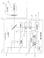
- FIG. 1 is a diagram showing a schematic configuration of an imaging system 1 which is an embodiment of an imaging apparatus of the present invention.
- the imaging system 1 includes a lens system 100 and a camera body 200.
- the lens system 100 includes a lens device 110 and a movable lens operation device 120.
- the lens device 110 includes a focus lens 111, a focus lens driving unit 112, a lens control unit 113, a communication interface (hereinafter abbreviated as I / F) 114, and a half mirror 115.
- the focus lens 111 is a movable lens that can move in the optical axis direction.
- the focus lens is a lens that adjusts the focal position by moving in the optical axis direction.
- the lens device 110 includes other optical systems such as a lens and a diaphragm for forming a subject image on the image sensor 210.
- An imaging optical system of the lens apparatus 110 is configured by the focus lens and this optical system.
- the focus lens driving unit 112 is hardware for adjusting the focus by moving the focus lens 111 in the optical axis direction, and includes a motor or the like.
- the communication I / F 114 is an interface for communicating with the movable lens operating device 120 by wire or wireless.
- the half mirror 115 is an optical element arranged on the optical path of the imaging optical system including the focus lens 111.
- the half mirror 115 reflects a part of the light that has passed through the focus lens 111 and guides it to the lens control unit 113, and transmits the remainder of the light that has passed through the focus lens 111 to guide it to the image sensor 210.
- the lens control unit 113 is configured mainly with a processor, and includes a ROM (Read Only Memory) in which a program executed by the processor is stored, a RAM (Random Access Memory) as a work memory, and the like.
- ROM Read Only Memory
- RAM Random Access Memory
- the ROM of the lens control unit 113 is a computer-readable non-transitory storage medium.
- the program stored in the ROM is stored in advance by being input from an electronic device such as a personal computer in addition to the program stored in advance when the lens device 110 is manufactured, or downloaded and stored in the lens device 110 via a network. It may be what you did.
- the lens control unit 113 controls the focus lens driving unit 112 to adjust the position of the focus lens 111 in the optical axis direction, thereby adjusting the focal position.
- the lens control unit 113 drives and controls the focus lens driving unit 112 based on the focus control signal received from the movable lens operating device 120 via the communication I / F 114, and the position of the focus lens 111 designated by the focus control signal.
- the first drive to move to is performed.
- the lens control unit 113 calculates a target position of the focus lens 111 (hereinafter referred to as a focus target position) by the phase difference AF method based on the reflected light from the half mirror 115, and uses the calculated focus target position information as a movable lens operation. To device 120.
- the movable lens operation device 120 includes an operation member 121, a position detection unit 122, an operation member drive unit 123, an operation control unit 124, and a communication I / F 125.
- the operation member 121 is a movable member for moving the focus lens 111 manually.
- Examples of the operation member 121 include a rotatable member or a slidable member.
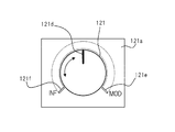
- FIG. 2 is a schematic diagram showing a configuration example of the operation member 121 shown in FIG.
- the operation member 121 is constituted by a rotor that is rotatably supported with respect to the base 121a.
- the base 121a has a first scale 121e indicating the closest end in the movable range of the focus lens 111 and a second scale 121f indicating the infinite end in the movable range of the focus lens 111.
- the range indicated by the broken line connecting the first scale 121e and the second scale 121f in the rotation direction of the operation member 121 corresponds to the movable range of the focus lens 111.
- the operation member 121 shown in FIG. 2 has a third scale 121d indicating the current position of the focus lens 111.
- a third scale 121d indicating the current position of the focus lens 111.
- the third scale 121 d of the operation member 121 is the same as the position of the first scale 121 e in the movement direction of the operation member 121, so that the second scale 121 f in the movement direction of the operation member 121 is changed.
- the operation member 121 can be rotated until the position becomes the same.
- the position of the third scale 121d in the moving direction of the operation member 121 is defined as the position of the operation member 121.
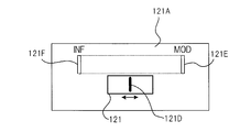
- FIG. 3 is a schematic diagram showing another configuration example of the operation member 121 shown in FIG.
- the operation member 121 is constituted by a slide member that is supported so as to be movable in the left-right direction with respect to the base 121A.
- the base 121A has a fourth scale 121E indicating the closest end in the movable range of the focus lens 111 and a fifth scale 121F indicating the infinite end in the movable range of the focus lens 111.
- the range indicated by the broken line connecting the fourth scale 121E and the fifth scale 121F in the rotation direction of the operation member 121 corresponds to the movable range of the focus lens 111.
- the operation member 121 shown in FIG. 3 has a sixth scale 121D indicating the current position of the focus lens 111.
- a sixth scale 121D indicating the current position of the focus lens 111.
- the sixth scale 121D of the operation member 121 is the same as the position of the fourth scale 121E in the movement direction of the operation member 121, so that the fifth scale 121F in the movement direction of the operation member 121 is changed.
- the operation member 121 can be slid until the position becomes the same.
- the position of the sixth scale 121D in the moving direction of the operation member 121 is defined as the position of the operation member 121.
- the position detection unit 122 of the movable lens operating device 120 is hardware for detecting the position of the operation member 121 (hereinafter referred to as an operation position), and uses a Hall element, a magnetoresistive effect element, or the like. A sensor is used.
- the operation position signal detected by the position detection unit 122 is sent to the operation control unit 124.
- the position detection unit 122 constitutes an operation member position detection unit.
- the operation member driving unit 123 is hardware for driving the operation member 121, and includes a motor or the like.
- the communication I / F 125 is an interface for communicating with the lens apparatus 110 by wireless or wired.
- the operation control unit 124 is configured mainly with a processor, and includes a ROM that stores a program executed by the processor, a RAM as a work memory, and the like.
- the ROM of the operation control unit 124 stores data indicating the correspondence between the position of the focus lens 111 and the operation position of the operation member 121 in advance.
- the operation control unit 124 drives and controls the operation member driving unit 123 based on the focus target position information received from the lens device 110, thereby moving the operation member 121 to the operation position corresponding to the focus target position.
- the operation control unit 124 Based on the operation position signal input from the position detection unit 122, the operation control unit 124 transmits a focus control signal including information on the operation position based on the operation position signal to the lens device 110 via the communication I / F 125. To do.
- the operation control unit 124 constitutes an operation member position transmission unit.
- the camera body 200 includes an image sensor 210 and an image processing unit 220.
- the imaging element 210 captures a subject image formed by the imaging optical system of the lens device 110 and outputs a captured image signal.
- the image processing unit 220 performs signal processing on the captured image signal output from the image sensor 210 and outputs it as a video signal.
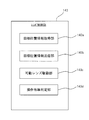
- FIG. 4 is a functional block diagram of the lens control unit 113 shown in FIG.
- the lens control unit 113 includes a target position information acquisition unit 113a, a target position information transmission unit 113b, a movable lens driving unit 113c, and an operation presence / absence determination unit 113d.
- the processor of the lens control unit 113 executes a program stored in the ROM of the lens control unit 113. It is constituted by.
- This program includes a lens driving program.
- the ROM of the lens control unit 113 stores data indicating the correspondence between the operation position of the operation member 121 and the position of the focus lens 111 in the optical axis direction in advance.
- the target position information acquisition unit 113a calculates the focus target position by the phase difference AF method based on the reflected light from the half mirror 115, and acquires the information of the focus target position by calculation.
- the method by which the target position information acquisition unit 113a calculates the focus target position is not limited to the phase difference AF method, and for example, a contrast AF method may be employed.
- the target position information acquisition unit 113a controls the focus lens driving unit 112 to sequentially move the focus lens 111, and the focus lens 111 is in each moving position.
- a captured image signal obtained by imaging with the imaging element 210 is acquired.
- the target position information acquisition unit 113a calculates a contrast evaluation value based on the acquired captured image signal, and sets the position of the focus lens 111 when the contrast evaluation value is maximized as the focus target position.
- the target position information transmission unit 113b transmits information on the focus target position acquired by the target position information acquisition unit 113a to the movable lens operating device 120 via the communication I / F 114.
- the movable lens driving unit 113c Based on the focus control signal received from the movable lens operating device 120, the movable lens driving unit 113c reads the position of the focus lens 111 corresponding to the operation position included in the focus control signal from the ROM of the lens control unit 113, and reads it out. A first drive for moving the focus lens 111 to a position is performed.
- the operation presence / absence determination unit 113d determines whether or not the operation member 121 is being operated. This determination method is arbitrary.
- the operation presence / absence determination unit 113d acquires an output signal from a pressure sensor or the like provided on the operation member 121 from the movable lens operation device 120, and whether the operation member 121 is touched by the operator based on the acquired output signal. The above determination is made depending on whether or not.
- the operation presence / absence determining unit 113d includes information on the operation position corresponding to the focus target position acquired by the target position information acquisition unit 113a, and information on the operation position detected by the position detection unit 122 of the movable lens operating device 120. Is acquired from the movable lens operating device 120.
- the operation presence / absence determination unit 113d determines that the operation member 121 is operated when the difference between the two operation positions is equal to or greater than the threshold, and when the difference is less than the threshold, the operation member 121 is not operated. It is determined that
- the two operation positions almost coincide with each other when the operation member 121 is not operated. Therefore, it is possible to determine whether or not the operation member 121 is operated based on the difference between the two operation positions.
- the lens control unit 113 may make the above determination.
- the focus target position is periodically calculated in the lens device 110, and information on the focus target position is transmitted to the movable lens operation device 120.
- the operation control unit 124 of the movable lens operating device 120 When the operation control unit 124 of the movable lens operating device 120 receives the information about the focus target position from the lens device 110, the operation control unit 124 reads the operation position corresponding to the focus target position from the ROM, and moves the operation member 121 to the read operation position. Move.
- the operation position of the operation member 121 is always detected in the movable lens operation device 120, and a focus control signal including the detected operation position is transmitted from the movable lens operation device 120 to the lens device 110. Is done.
- the movable lens driving unit 113c of the lens device 110 moves the focus lens 111 to a position corresponding to the current operation position based on the focus control signal. Drive.
- the focus lens 111 is driven to the focus target position when the operation member 121 is not operated.
- the operation position of the operation member 121 changes according to the focus target position.
- the operation presence / absence determination unit 113d of the lens device 110 determines that the operation member 121 is operated, and the operation control unit 124 of the movable lens operation device 120
- the driving force of the operating member 121 by the operating member driving unit 123 is controlled to the first driving force.
- the operation presence / absence determination unit 113d of the lens device 110 determines that the operation member 121 is not operated, and the operation control unit 124 of the movable lens operation device 120 operates the operation member drive.
- the driving force of the operation member 121 by the unit 123 is controlled to the second driving force.
- the second driving force is a value larger than the first driving force.
- the operation control unit 124 may control the driving force of the operation member 121 by the operation member driving unit 123 to be constant regardless of whether the operation member 121 is operated.
- the focus lens 111 moves to a position corresponding to the operation position. That is, the focus adjustment in the MF mode is possible.
- the operation position of the operation member 121 changes according to the focus target position calculated by the lens device 110. Thereby, the user of the imaging system 1 can intuitively grasp the focus target position determined by the lens device 110.
- the movement of the operation member 121 can be used as a reference in focus adjustment in the MF mode, and the photographing operation can be supported. it can.
- the operation member 121 is always driven based on the focus target position calculated by the lens device 110 regardless of the presence or absence of the operation.
- the user intuitively grasps the focus target position relative to the current position by the driving force of the operation member 121 by the operation member drive unit 123. can do.
- the movement of the operation member 121 can be used as a reference during focus adjustment in the MF mode, and the photographing operation can be supported.
- the imaging system 1 when the operation member 121 is operated, the driving force of the operation member 121 is controlled to be smaller than when the operation member 121 is not operated. For this reason, the operation member 121 can be easily moved during focus adjustment in the MF mode, and operability can be improved.
- the imaging system 1 since the focus lens 111 moves according to the operation position of the operation member 121, the versatility with respect to the existing system is high, and the system can be simplified and the manufacturing cost can be reduced. .
- the operation member driving unit 123 stops driving the operation member 121 when the operation member 121 is determined to be operated by the operation presence / absence determination unit 113 d of the lens device 110. Good.
- the movable lens driving unit 113 c of the lens control unit 113 moves the focus lens 111 to the focus target position based on the focus target position information acquired by the target position information acquisition unit 113 a.
- the first driving may be selectively performed.
- Switching between the first driving and the second driving is performed according to an operation of a switching button provided in the lens system 100, for example.
- the focus lens 111 can be driven regardless of the drive capability of the operation member 151, and flexible focus adjustment is possible.
- first drive and the second drive can be switched depending on the operation state of the operation member 121 without using the switching button.
- the movable lens driving unit 113c performs the first drive when the operation presence / absence determination unit 113d determines that the operation member 121 is operated, and the operation presence / absence determination unit 113d does not operate the operation member 121. If it is determined that there is, the second drive is performed.
- the manufacturing cost of the lens system 100 can be reduced.
- the drive of the operation member 121 is stopped or the operation is performed.
- the operability can be improved by making the driving force of the member 121 smaller than when the second driving is performed.
- FIG. 5 is a diagram showing a schematic configuration of an imaging system 2 which is a modification of the imaging system 1 shown in FIG.
- the imaging system 2 is a system that can remotely control the position of the focus lens 111 in the lens device 110.
- the imaging system 2 has the same configuration as the imaging system 1 except that the communication I / F 117 and the electronic device 300 are added and the function of the lens control unit 113 is partially different.
- FIG. 5 the same components as those in FIG.
- the electronic device 300 is an electronic device that can input information to the lens device 110, and is, for example, a personal computer.
- the communication I / F 117 of the lens apparatus 110 is an interface for communicating with the electronic device 300 wirelessly or by wire.
- the communication I / F 117 constitutes a communication unit for communicating with the electronic device 300.
- the functional block diagram of the lens control unit 113 is the same as the configuration shown in FIG. 4, but the function of the target position information acquisition unit 113a is different, and will be described below.
- the target position information acquisition unit 113a of the lens control unit 113 in the imaging system 2 operates in either the remote acquisition mode or the calculation acquisition mode.
- the remote acquisition mode is a mode for acquiring information on the focus target position from the electronic device 300 via the communication I / F 117.
- the calculation acquisition mode is a mode for acquiring information on the focus target position by calculation using the phase difference AF method or the contrast AF method as described above.
- Switching between the remote acquisition mode and the calculation acquisition mode is performed by operating a button (not shown) provided in the imaging system 2.
- the imaging system 2 configured as described above, the same effect as the imaging system 1 can be obtained.
- the remote acquisition mode and the calculation acquisition mode can be switched, it is possible to cope with the case where the position of the focus lens 111 is controlled remotely.
- the user of the imaging system 2 can grasp the intention of the person who indicates the target position of the focus lens 111 by confirming the operation position of the operation member 121.
- the movable lens driving unit 113c of the lens control unit 113 can selectively perform the first driving and the second driving.
- the target position information acquisition unit 113a of the lens control unit 113 in the imaging system 2 may be configured to operate only in the remote acquisition mode. In this case, the half mirror 115 is unnecessary in FIG.
- FIG. 6 is a diagram showing a schematic configuration of an imaging system 3 which is a modification of the imaging system 1 shown in FIG.
- the imaging system 3 has the same configuration as that of FIG. 1 except that the adjustment unit 126 is added to the movable lens operating device 120.
- the same components as those in FIG. 6 are identical components as those in FIG.
- the adjusting unit 126 adjusts the driving force of the operation member 121 by the operation member driving unit 123.
- the adjusting unit 126 changes the driving force by electrically changing the driving force of the operating member 121 by the operating member driving unit 123.
- the adjustment unit 126 adds a member that attenuates the force, such as a damper, to the operation member 121, thereby changing the amount of movement when the operation member 121 is moved with a predetermined force to change the driving force. It may be a thing.
- the driving force by the operation member driving unit 123 can be adjusted according to the user's preference. Further, since the driving force by the operating member driving unit 123 can be adjusted, the response of movement of the focus lens 111 in the MF mode can be adjusted without changing the lens device 110, and the manufacturing cost of the system can be reduced. can do.
- the adjustment unit 126 can be similarly applied to the imaging system 2 shown in FIG.
- the movable lens included in the lens device 110 is a focus lens
- the present invention can also be applied to a zoom lens that can move in the optical axis direction for adjusting the focal length.
- FIG. 7 is a diagram showing a schematic configuration of an imaging system 4 which is an embodiment of the imaging apparatus of the present invention.
- the imaging system 4 includes a lens system 100A, a camera body 200A, and an electronic device 300A.
- the lens system 100A includes a lens device 140 and a movable lens operation device 150.
- the electronic device 300 is an electronic device that can input information to the lens device 140, and is, for example, a personal computer.
- the lens device 140 includes a zoom lens 141, a zoom lens driving unit 142, a lens control unit 143, a communication I / F 144, and a communication I / F 145.
- the zoom lens 141 is a movable lens that can move in the optical axis direction.
- a zoom lens is a lens that adjusts the focal length by moving in the optical axis direction.
- the lens device 140 includes other optical systems such as a lens and a diaphragm for forming a subject image on the image sensor 210A.
- the zoom lens and this optical system constitute an imaging optical system of the lens device 140.
- the zoom lens driving unit 142 is hardware for adjusting the focal length by moving the zoom lens 141 in the optical axis direction, and includes a motor or the like.
- the communication I / F 144 is an interface for communicating with the movable lens operating device 150 in a wired or wireless manner.
- the communication I / F 145 is an interface for communicating with the electronic device 300 by wireless or wired.
- the communication I / F 145 constitutes a communication unit for communicating with the electronic device 300.
- the lens control unit 143 is configured mainly with a processor, and includes a ROM for storing a program executed by the processor, a RAM as a work memory, and the like.
- the ROM of the lens control unit 143 is a computer-readable non-transitory storage medium.
- the program stored in the ROM is stored in advance by being input from an electronic device such as a personal computer in addition to the program stored in advance when the lens device 140 is manufactured, or downloaded and stored in the lens device 140 via a network. It may be what you did.
- the lens control unit 143 controls the zoom lens driving unit 142 to adjust the position of the zoom lens 141 in the optical axis direction, thereby adjusting the focal length.
- the lens control unit 143 transmits information on the target position of the zoom lens 141 (hereinafter referred to as the zoom target position) acquired from the electronic device 300 to the movable lens operating device 150.
- the movable lens operation device 150 includes an operation member 151, a position detection unit 152, an operation member drive unit 153, an operation control unit 154, and a communication I / F 155.
- the operation member 151 is a movable member for moving the zoom lens 141 manually.
- Examples of the operation member 151 include a rotatable member or a slidable member as illustrated in FIG. 2 or FIG.
- the operation member 151 is changed from the operation member 121 to the operation member 151, the first scale 121 e is changed to information indicating the wide end, and the second scale 121 f is changed to information indicating the tele end.
- the position of the third scale 121 d in the movement direction of the operation member 151 is defined as the position of the operation member 151.
- the position detection unit 152 is hardware for detecting the position of the operation member 151 (hereinafter referred to as an operation position), and a sensor using a Hall element or a magnetoresistive element or the like is used.
- the operation position signal detected by the position detection unit 152 is sent to the operation control unit 154.
- the position detector 152 constitutes an operation member position detector.
- the operation member drive unit 153 is hardware for driving the operation member 151, and includes a motor or the like.
- the communication I / F 155 is an interface for communicating with the lens device 140 wirelessly or by wire.
- the operation control unit 154 is configured mainly with a processor, and includes a ROM that stores a program executed by the processor, a RAM as a work memory, and the like.
- ROM of the operation control unit 154 data indicating the correspondence between the position of the zoom lens 141 and the operation position of the operation member 151 is stored in advance.
- the operation control unit 154 drives and controls the operation member driving unit 153 based on the information about the zoom target position received from the lens device 140, thereby moving the operation member 151 to the operation position corresponding to the zoom target position.
- the operation control unit 154 Based on the operation position signal input from the position detection unit 152, the operation control unit 154 transmits a zoom control signal including operation position information based on the operation position signal to the lens device 140 via the communication I / F 155. To do.
- the operation control unit 154 constitutes an operation member position transmission unit.
- the camera body 200A includes an image sensor 210A and an image processing unit 220A.
- the image sensor 210A captures a subject image formed by the imaging optical system of the lens device 140 and outputs a captured image signal.
- the image processing unit 220A performs signal processing on the captured image signal output from the image sensor 210A and outputs it as a video signal.
- FIG. 8 is a functional block diagram of the lens control unit 143 shown in FIG.
- the lens control unit 143 includes a target position information acquisition unit 143a, a target position information transmission unit 143b, a movable lens driving unit 143c, and an operation presence / absence determination unit 143d.
- the processor of the lens control unit 143 executes the program stored in the ROM of the lens control unit 143. It is constituted by.
- This program includes a lens driving program.
- ROM of the lens control unit 143 data indicating the correspondence between the operation position of the operation member 151 and the position of the zoom lens 141 in the optical axis direction is stored in advance.
- the target position information acquisition unit 143a acquires information on the zoom target position from the electronic device 300.
- the target position information transmission unit 143b transmits information on the zoom target position acquired by the target position information acquisition unit 143a to the movable lens operating device 150 via the communication I / F 144.
- the operation presence / absence determination unit 143d determines whether or not the operation member 151 is being operated. This determination method is arbitrary.
- the operation presence / absence determining unit 143d acquires an output signal from a pressure sensor or the like provided on the operation member 151 from the movable lens operation device 150, and whether the operation member 151 is touched by the operator based on the acquired output signal. The above determination is made depending on whether or not.
- the operation presence / absence determining unit 143d includes information on the operation position corresponding to the zoom target position acquired by the target position information acquisition unit 143a, and information on the operation position detected by the position detection unit 152 of the movable lens operating device 150. Is acquired from the movable lens operating device 150.
- the operation presence / absence determining unit 143d determines that the operation member 151 is operated when the difference between the two operation positions is equal to or greater than the threshold, and when the difference is less than the threshold, the operation member 151 is not operated. It is determined that
- the operation control unit 154 may determine whether or not the operation member 151 is operated by the method described above, and may transmit information indicating the determination result to the lens control unit 143. Based on this information, the lens control unit 143 may make the above determination.
- the movable lens driving unit 143c Based on the zoom control signal received from the movable lens operating device 150, the movable lens driving unit 143c reads out the position of the zoom lens 141 corresponding to the operation position included in the zoom control signal from the ROM of the lens control unit 143. A first drive for moving the zoom lens 141 to the position is performed.
- information on the zoom target position is periodically transmitted from the electronic device 300 to the lens control unit 143.
- the lens control unit 143 of the lens device 140 acquires information on the zoom target position from the electronic device 300, the lens control unit 143 transmits the information on the zoom target position to the operation control unit 154.
- the operation control unit 154 of the movable lens operation device 150 When the operation control unit 154 of the movable lens operation device 150 receives information on the zoom target position from the lens device 140, the operation control unit 154 reads the operation position corresponding to the zoom target position from the ROM, and moves the operation member 151 to the read operation position. .
- the operation position of the operation member 151 is always detected by the movable lens operation device 150, and a zoom control signal including the detected operation position is transmitted from the movable lens operation device 150 to the lens device 140. Is done.
- the movable lens driving unit 143c of the lens device 140 moves the zoom lens 141 to a position corresponding to the current operation position based on the zoom control signal. Drive.
- the zoom lens 141 is driven to the zoom target position designated by the electronic device 300.
- the operation position of the operation member 151 changes according to the zoom target position designated from the electronic device 300.
- the operation member 151 When the operation member 151 is operated during the operation of the imaging system 4, it is determined that the operation member 151 is operated by the operation presence / absence determination unit 143d of the lens device 140, and the operation control unit 154 of the movable lens operation device 150 is The driving force of the operation member 151 by the operation member drive unit 153 is controlled to a value smaller than that when the operation member 151 is not operated.
- the operation control unit 154 may control the driving force of the operation member 151 by the operation member driving unit 153 to be constant regardless of whether the operation member 151 is operated.
- the zoom lens 141 moves to a position corresponding to the operation position. In other words, manual zoom adjustment is possible.
- the operation member 151 is moved to the operation position based on the zoom target position acquired by the lens control unit 143. Then, the zoom lens 141 moves to a position corresponding to the operation position of the operation member 151.
- the user of the imaging system 4 can intuitively grasp the zoom target position designated from the electronic device 300.
- the zoom target position designated by the electronic device 300 can be grasped, it can be used as a reference when manually adjusting the focal length, and the photographing operation can be supported.
- the operation member 151 is always driven based on the zoom target position acquired by the lens device 140 regardless of the presence or absence of the operation.
- the user intuitively grasps where the zoom target position is relative to the current position by the driving force of the operation member 151 by the operation member drive unit 153. can do.
- the movement of the operation member 151 can be used as a reference when manually adjusting the focal length, and the photographing operation can be supported.
- the driving force of the operation member 151 is controlled to be smaller than when the operation member 151 is not operated. For this reason, it becomes easy to move the operation member 151 during the focal length adjustment, and the operability can be improved.
- the imaging system 4 since the zoom lens 141 is moved according to the operation position of the operation member 151, the versatility with respect to the existing system is high, and the system can be simplified and the manufacturing cost can be suppressed.
- the operation member driving unit 153 may stop driving the operation member 151 when the operation member 151 is determined to be operated by the operation presence / absence determination unit 143 d of the lens device 140. Good.
- the operation member 121 can be easily moved during manual focal length adjustment, and operability can be improved.
- the movable lens driving unit 143 c of the lens control unit 143 moves the zoom lens 141 to the zoom target position based on the information on the zoom target position acquired by the target position information acquisition unit 143 a.
- the first driving may be selectively performed.
- the switching between the first drive and the second drive is performed, for example, according to an operation of a switch button provided in the lens system 100A.
- the zoom lens 141 can be driven regardless of the drive capability of the operation member 151, and flexible zoom control can be performed.
- first drive and the second drive can be switched depending on the operation state of the operation member 151 without using the switching button.
- the movable lens driving unit 143c performs the first drive when the operation presence / absence determination unit 143d determines that the operation member 151 is operated, and the operation presence / absence determination unit 143d does not operate the operation member 151. If it is determined that there is, the second drive is performed.
- the operability can be improved by making the driving force of the operating member 151 smaller than when the second driving is performed.
- the adjustment unit 126 illustrated in FIG. 6 may be applied to adjust the driving force of the operation member 151 by the operation member driving unit 153.
- the lens device and the movable lens operating device may be integrated.
- the lens control unit also functions as an operation control unit, and the operation member, the operation member drive unit, and the position detection unit constitute a movable lens operation device.
- the imaging system 1 and the imaging system 3 can be applied to a lens-integrated digital camera, a lens interchangeable digital camera, and a broadcasting imaging system.
- the imaging system 2 and the imaging system 4 can be applied to an imaging system for broadcasting.
- the disclosed lens device includes a movable lens that can move in the optical axis direction, a target position information acquisition unit that acquires information on a target position of the movable lens, and a movable operation member that moves the movable lens. Detected by a target position information transmitting unit that transmits information on the target position and an operating member position detecting unit that detects the position of the operating member with respect to a movable lens operating device including an operating member driving unit that drives the operating member. A movable lens driving unit that performs a first drive for moving the movable lens based on the position of the operated member, and the operating member driving unit drives the operating member based on the information on the target position. Lens device to do.
- the movable lens driving unit selectively performs a second drive for moving the movable lens to the target position based on the information on the target position, and the first drive.
- Lens device In the disclosed lens apparatus, the movable lens driving unit selectively performs a second drive for moving the movable lens to the target position based on the information on the target position, and the first drive. Lens device.
- the disclosed lens device further includes an operation presence / absence determining unit that determines whether or not the operation member is operated, and the movable lens driving unit is configured to perform the first operation when the operation member is operated.
- a lens device that performs driving and performs the second driving when the operation member is not operated.
- the operation member driving unit drives the operation member based on the information on the target position in each of the case where the operation member is operated and the case where the operation member is not operated. Lens device.
- the disclosed lens device is a lens device in which the operation member driving unit makes the driving force of the operation member smaller when the operation member is operated than when the operation member is not operated.
- the disclosed lens device is a lens device in which the operation member driving unit stops driving the operation member when the operation member is operated.
- the operation presence / absence determination unit is configured such that a difference between the position of the operation member based on the information on the target position and the position of the operation member detected by the operation member position detection unit is greater than or equal to a threshold value. In this case, the lens device determines that the working member is operated.
- the disclosed lens device is a lens device in which the operation member driving unit makes the driving force of the operation member smaller when the operation member is operated than when the operation member is not operated.
- the disclosed lens device is a lens device in which the operation member driving unit stops driving the operation member when the operation member is operated.
- the disclosed lens device includes an operation presence / absence determination unit that determines whether or not the operation member is operated.
- the operation presence / absence determination unit includes the position of the operation member based on the information on the target position, and the operation.
- a lens device that determines that the operation member is operated when a difference from the position of the operation member detected by the member position detection unit is equal to or greater than a threshold value.
- the disclosed lens device is a lens device in which the target position information acquisition unit acquires the target position information by calculating the target position based on light that has passed through the movable lens.
- the disclosed lens device further includes a communication unit for communicating with an electronic device, and the target position information acquisition unit acquires information on the target position from the electronic device via the communication unit.
- the disclosed lens system is a lens system including the lens device, and a movable lens operation device including the operation member, the operation member driving unit, and the operation member position detection unit.
- the disclosed lens system further includes an adjustment unit that adjusts the driving force by the operation member driving unit.
- the disclosed imaging apparatus is an imaging apparatus including the lens system and an imaging element that images a subject through the movable lens of the lens apparatus.
- the disclosed movable lens operation device is a movable lens operation device configured to be able to communicate with a lens device including a movable lens movable in the optical axis direction, and is a movable operation member for moving the movable lens.
- An operation member drive unit that drives the operation member based on information on a target position of the movable lens received from the lens device, an operation member position detection unit that detects the position of the operation member, and the operation member
- An operation member position transmission unit that transmits position information to a movable lens drive unit of the lens device that performs first drive for moving the movable lens based on the position of the operation member.
- the movable lens driving unit selectively selects a second drive for moving the movable lens to the target position based on the information on the target position, and the first drive.
- a movable lens operating device selectively selects a second drive for moving the movable lens to the target position based on the information on the target position, and the first drive.
- the disclosed movable lens operating device further includes an operation presence / absence determining unit that determines whether or not the operating member is operated, and the movable lens driving unit is operated by the operating member.
- a movable lens operating device that performs the first driving in the case, and performs the second driving when the operation member is not operated.
- the operating member driving unit moves the operating member based on the information on the target position when the operating member is operated and when the operating member is not operated.
- a movable lens operating device to drive.
- the operating member driving unit is configured such that when the operating member is operated, the moving lens that reduces the driving force of the operating member is smaller than when the operating member is not operated.
- the disclosed movable lens operating device is a movable lens operating device in which the operating member driving unit stops driving the operating member when the operating member is operated.
- the operation presence / absence determining unit is configured such that a difference between a position of the operating member based on the information on the target position and a position of the operating member detected by the operating member position detecting unit is a threshold value.
- a movable lens operating device that determines that the operating member is operated in the above case.
- the operating member driving unit is configured such that when the operating member is operated, the moving lens that reduces the driving force of the operating member is smaller than when the operating member is not operated.
- the disclosed movable lens operating device is a movable lens operating device in which the operating member driving unit stops driving the operating member when the operating member is operated.
- the disclosed movable lens operating device includes an operation presence / absence determination unit that determines whether or not the operation member is operated, and the operation presence / absence determination unit is configured to perform the operation based on information on the target position.
- a movable lens operating device that determines that the operation member is operated when a difference between the position of the member and the position of the operation member detected by the operation member position detection unit is equal to or greater than a threshold value.
- the disclosed movable lens operating device is a movable lens operating device further comprising an adjusting unit for adjusting the driving force by the operating member driving unit.
- the disclosed lens driving method includes a target position information acquisition step for acquiring information on a target position of a movable lens movable in the optical axis direction, and a movable operation member for moving the movable lens at the target position. Detected by a target position information transmitting step for transmitting information on the target position to a movable lens operating device including an operating member driving unit that is driven based on information, and an operating member position detecting unit for detecting the position of the operating member
- a lens driving method comprising: a movable lens driving step for performing a first drive for moving the movable lens based on the position of the operation member.
- the second driving for moving the movable lens to the target position based on the information on the target position and the first driving are selectively performed.
- the disclosed lens driving method further includes an operation presence / absence determining step for determining whether or not the operation member is operated, and the movable lens driving step includes the first operation when the operation member is operated.
- the operating member driving unit drives the operating member based on the target position information when the operating member is operated and when the operating member is not operated. To drive the lens.
- the disclosed lens driving method is a lens driving method in which the operating member driving unit reduces the driving force of the operating member when the operating member is operated, compared to when the operating member is not operated. .
- the disclosed lens driving method is a lens driving method in which the operation member driving unit stops driving the operation member when the operation member is operated.
- a difference between the position of the operation member based on the information on the target position and the position of the operation member detected by the operation member position detection unit is greater than or equal to a threshold value.
- a lens driving method for determining that the operation member is operated.
- the disclosed lens driving method is a lens driving method in which the operating member driving unit reduces the driving force of the operating member when the operating member is operated, compared to when the operating member is not operated. .
- the disclosed lens driving method is a lens driving method in which the operation member driving unit stops driving the operation member when the operation member is operated.
- the disclosed lens driving method includes an operation presence / absence determination step for determining whether or not the operation member is operated, and the operation presence / absence determination step includes the position of the operation member based on the information on the target position,
- the disclosed lens driving method is a lens driving method in which the target position information acquisition step acquires the target position information by calculating the target position based on light that has passed through the movable lens.
- the disclosed lens driving method is a lens driving method in which the target position information acquisition step acquires the information of the target position from an electronic device that can communicate with a lens device including the movable lens.
- the disclosed lens driving program includes a target position information acquisition step for acquiring information on a target position of a movable lens movable in the optical axis direction, and a movable operation member for moving the movable lens at the target position. Detected by a target position information transmitting step for transmitting information on the target position to a movable lens operating device including an operating member driving unit that is driven based on information, and an operating member position detecting unit for detecting the position of the operating member A lens driving program for causing a computer to execute a movable lens driving step for performing a first driving for moving the movable lens based on the position of the operation member.
- a lens device capable of assisting a photographing operation by intuitively grasping the position of the movable lens. Can do.
- Imaging system 100 Lens system 110 Lens device 111 Focus lens 112 Focus lens drive unit 113 Lens control unit 113a Target position information acquisition unit 113b Target position information transmission unit 113c Movable lens drive unit 113d Operation presence / absence determination units 114 and 117 , 125 Communication I / F 115 half mirror 120 movable lens operating device 121 operation member 121a, 121A base 121e first scale 121f second scale 121d third scale 121E fourth scale 121F fifth scale 121D sixth scale 122 position detection unit 123 operation member drive unit 124 operation Control unit 126 Adjustment unit 200 Camera body 210 Image sensor 220 Image processing unit 300 Electronic device 4 Imaging system 100A Lens system 140 Lens device 141 Zoom lens 142 Zoom lens driving unit 143 Lens control unit 143a Target position information acquisition unit 143b Target position information transmission Unit 143c movable lens drive unit 143d operation presence / absence determination unit 144, 145, 155 communication I / F 150 Movable Lens Operation Device 151 Operation Member 152 Position
Landscapes
- Physics & Mathematics (AREA)
- General Physics & Mathematics (AREA)
- Engineering & Computer Science (AREA)
- Multimedia (AREA)
- Signal Processing (AREA)
- Optics & Photonics (AREA)
- General Engineering & Computer Science (AREA)
- Lens Barrels (AREA)
- Automatic Focus Adjustment (AREA)
- Focusing (AREA)
Abstract
可動レンズの位置を直感的に把握可能として撮影操作を支援することができるレンズ装置、レンズシステム、撮像装置、可動レンズ操作装置、レンズ駆動方法、レンズ駆動プログラムを提供する。レンズ装置110は、フォーカス位置を取得し、その位置を目標位置としてフォーカスレンズ111を移動させると同時に、その目標位置の情報を可動レンズ操作装置120に送信する。可動レンズ操作装置120は、レンズ装置110から受信した目標位置の情報に基づいて操作部材121を駆動する。フォーカスレンズ111を移動させるとともに操作部材121を駆動することにより、フォーカスレンズ111の位置と操作部材121の操作位置とを連動させる。
Description
本発明は、レンズ装置、レンズシステム、撮像装置、可動レンズ操作装置、レンズ駆動方法、レンズ駆動プログラムに関する。
光軸方向に移動可能で焦点位置を変えるためのフォーカスレンズを含むレンズ装置と、このフォーカスレンズを手動で移動させるための操作装置と、を有するレンズシステムが知られている。操作装置としては、回転自在の操作部材を回転させることでフォーカスレンズを移動させる、いわゆるフォーカスデマンド等がある。
このようなレンズシステムにおいて、レンズ装置がフォーカスレンズを自動で移動させるAF(Auto Focus)制御を行うものがある(特許文献1,2参照)。
特許文献1及び特許文献2には、AF制御を行っている状態で操作装置が操作されると、操作装置の操作に応じてフォーカスレンズを移動させるMF(Manual Focus)制御に切り換えるレンズシステムが記載されている。
特許文献1,2のように、MF制御を行うための操作装置に、AF制御とMF制御の切り替え指示を行う機能を持たせることで、この切り替え指示のための専用の部材を不要としてレンズシステムの簡略化を図ることができる。
しかし、特許文献1,2では、AF制御中におけるフォーカスレンズの位置と操作部材の操作位置とはリンクしていないため、AF制御中におけるフォーカスレンズの位置を直感的に把握することはできない。
操作装置を見ることで、AF制御中におけるフォーカスレンズの位置を把握することができれば、機械が判断しているフォーカスレンズの位置を操作者が知ることができ、撮影操作を支援することができる。
なお、放送用のレンズシステムでは、レンズ装置におけるフォーカスレンズの位置を遠隔で制御できるシステムが存在する。
このシステムでは、レンズ装置を手に持って操作している操作者とは別の場所にいる人間が、レンズ装置と接続された電子機器を操作してフォーカスレンズの目標位置を指示する。レンズ装置は、AF制御時には、この指示された目標位置にフォーカスレンズを移動させる。
このように、AF制御時のフォーカスレンズの位置を遠隔で制御するシステムにおいても、操作装置を見ることで、フォーカスレンズの位置を指示している人間の意図を把握することができれば、現場の操作者に対する撮影操作の支援が可能になる。
ここまでは、レンズ装置に含まれる可動レンズとしてフォーカスレンズを例にした。レンズ装置に含まれる可動レンズとしては、光軸方向に移動可能で焦点距離を変えるためのズームレンズが存在する。
ズームレンズを含むレンズ装置と、このズームレンズを手動で移動させるための操作装置(いわゆるズームデマンド)と、を有するレンズシステムにおいても、ズームレンズの位置を遠隔で制御できる構成が考えられる。
この構成においても、ズームデマンドを見ることで、遠隔制御中におけるズームレンズの位置を把握することができれば、現場の操作者に対する撮影操作の支援が可能になる。
本発明は、上記事情に鑑みてなされたものであり、可動レンズの位置を直感的に把握可能として撮影操作を支援することができるレンズ装置、レンズシステム、撮像装置、可動レンズ操作装置、レンズ駆動方法、レンズ駆動プログラムを提供することを目的とする。
本発明のレンズ装置は、光軸方向に移動可能な可動レンズと、上記可動レンズの目標位置の情報を取得する目標位置情報取得部と、上記可動レンズを移動させるための移動自在な操作部材と上記操作部材を駆動する操作部材駆動部とを含む可動レンズ操作装置に対し、上記目標位置の情報を送信する目標位置情報送信部と、上記操作部材の位置を検出する操作部材位置検出部により検出された上記操作部材の位置に基づいて上記可動レンズを移動させる第一の駆動を行う可動レンズ駆動部と、を備え、上記操作部材駆動部は上記目標位置の情報に基づいて上記操作部材を駆動するものである。
本発明のレンズシステムは、上記レンズ装置と、上記操作部材、上記操作部材駆動部、及び、上記操作部材位置検出部を含む可動レンズ操作装置と、を備えるものである。
本発明の撮像装置は、上記レンズシステムと、上記レンズ装置の上記可動レンズを通して被写体を撮像する撮像素子と、を備えるものである。
本発明の可動レンズ操作装置は、光軸方向に移動可能な可動レンズを含むレンズ装置と通信可能に構成された可動レンズ操作装置であって、上記可動レンズを移動させるための移動自在な操作部材と、上記レンズ装置から受信した上記可動レンズの目標位置の情報に基づいて上記操作部材を駆動する操作部材駆動部と、上記操作部材の位置を検出する操作部材位置検出部と、上記操作部材の位置の情報を、上記操作部材の位置に基づいて上記可動レンズを移動させる第一の駆動を行う上記レンズ装置の可動レンズ駆動部に送信する操作部材位置送信部と、を備えるものである。
本発明のレンズ駆動方法は、光軸方向に移動可能な可動レンズの目標位置の情報を取得する目標位置情報取得ステップと、上記可動レンズを移動させるための移動自在な操作部材を上記目標位置の情報に基づいて駆動する操作部材駆動部を含む可動レンズ操作装置に、上記目標位置の情報を送信する目標位置情報送信ステップと、上記操作部材の位置を検出する操作部材位置検出部により検出された上記操作部材の位置に基づいて上記可動レンズを移動させる第一の駆動を行う可動レンズ駆動ステップと、を備えるものである。
本発明のレンズ駆動プログラムは、光軸方向に移動可能な可動レンズの目標位置の情報を取得する目標位置情報取得ステップと、上記可動レンズを移動させるための移動自在な操作部材を上記目標位置の情報に基づいて駆動する操作部材駆動部を含む可動レンズ操作装置に、上記目標位置の情報を送信する目標位置情報送信ステップと、上記操作部材の位置を検出する操作部材位置検出部により検出された上記操作部材の位置に基づいて上記可動レンズを移動させる第一の駆動を行う可動レンズ駆動ステップと、をコンピュータに実行させるためのものである。
本発明によれば、可動レンズの位置を直感的に把握可能として撮影操作を支援することができるレンズ装置、レンズシステム、撮像装置、可動レンズ操作装置、レンズ駆動方法、レンズ駆動プログラムを提供することができる。
図1は、本発明の撮像装置の一実施形態である撮像システム1の概略構成を示す図である。
撮像システム1は、レンズシステム100と、カメラ本体200と、を備える。
レンズシステム100は、レンズ装置110と、可動レンズ操作装置120と、を備える。
レンズ装置110は、フォーカスレンズ111と、フォーカスレンズ駆動部112と、レンズ制御部113と、通信インタフェース(以下、I/Fと略す)114と、ハーフミラー115と、を備える。
フォーカスレンズ111は、光軸方向に移動可能な可動レンズである。フォーカスレンズとは、光軸方向に移動することで、焦点位置を調整するレンズを言う。
なお、図示していないが、レンズ装置110には、被写体像を撮像素子210に結像させるためのレンズ及び絞り等の他の光学系も含まれる。フォーカスレンズとこの光学系とにより、レンズ装置110の撮像光学系が構成される。
フォーカスレンズ駆動部112は、フォーカスレンズ111を光軸方向に移動させてフォーカス調整を行うためのハードウェアであり、モータ等によって構成される。
通信I/F114は、可動レンズ操作装置120と有線又は無線により通信するためのインタフェースである。
ハーフミラー115は、フォーカスレンズ111を含む撮像光学系の光路上に配置された光学素子である。ハーフミラー115は、フォーカスレンズ111を通過した光の一部を反射させてレンズ制御部113に導き、フォーカスレンズ111を通過した光の残りを透過させて撮像素子210に導く。
レンズ制御部113は、プロセッサを主体に構成されており、プロセッサの実行するプログラム等が記憶されるROM(Read Only Memory)、及び、ワークメモリとしてのRAM(Random Access Memory)等を含む。
レンズ制御部113のROMは、コンピュータ読み取り可能な一時的でない(non-transitory)記憶媒体である。このROMに記憶されるプログラムは、レンズ装置110の製造時に予め記憶されるものの他、パーソナルコンピュータ等の電子機器から入力されて記憶されたり、レンズ装置110にネットワークを介してダウンロードされて記憶されたりしたものであってもよい。
レンズ制御部113は、フォーカスレンズ駆動部112を駆動制御することにより、フォーカスレンズ111の光軸方向の位置を調整して、焦点位置を調整する。
レンズ制御部113は、可動レンズ操作装置120から通信I/F114を介して受信したフォーカス制御信号に基づいてフォーカスレンズ駆動部112を駆動制御し、フォーカスレンズ111をこのフォーカス制御信号によって指定された位置に移動させる第一の駆動を行う。
レンズ制御部113は、ハーフミラー115からの反射光に基づいて位相差AF方式によりフォーカスレンズ111の目標位置(以下、フォーカス目標位置という)を算出し、算出したフォーカス目標位置の情報を可動レンズ操作装置120に送信する。
可動レンズ操作装置120は、操作部材121と、位置検出部122と、操作部材駆動部123と、操作制御部124と、通信I/F125と、を備える。
操作部材121は、フォーカスレンズ111を手動で移動させるための移動自在な部材である。操作部材121の例として、回動可能な部材又はスライド可能な部材を挙げることができる。
図2は、図1に示す操作部材121の構成例を示す模式図である。
図2に示す構成例では、操作部材121は、基体121aに対して回動自在に支持された回転子により構成されている。
基体121aには、フォーカスレンズ111の移動可能な範囲における最近接端を示す第一目盛121eと、フォーカスレンズ111の移動可能な範囲における無限遠端を示す第二目盛121fとが記されている。
操作部材121の回転方向において第一目盛121eと第二目盛121fとを結ぶ破線で示した範囲が、フォーカスレンズ111の移動可能な範囲に対応している。
図2に示す操作部材121には、現在のフォーカスレンズ111の位置を示す第三目盛121dが記されている。図2に示す構成例では、破線で示す範囲における第三目盛121dの位置によって、フォーカスレンズ111がどのあたりにあるのかを把握することが可能となっている。
図2に示す構成例では、操作部材121の第三目盛121dが、操作部材121の移動方向における第一目盛121eの位置と同じになる状態から、操作部材121の移動方向における第二目盛121fの位置と同じになる状態まで、操作部材121を回転させることができる。
図2に示す構成例では、操作部材121の移動方向における第三目盛121dの位置が、操作部材121の位置として定義される。
図3は、図1に示す操作部材121の別の構成例を示す模式図である。
図3に示す構成例では、操作部材121は、基体121Aに対して左右方向に移動自在に支持されたスライド部材により構成されている。
基体121Aには、フォーカスレンズ111の移動可能な範囲における最近接端を示す第四目盛121Eと、フォーカスレンズ111の移動可能な範囲における無限遠端を示す第五目盛121Fとが記されている。
操作部材121の回転方向において第四目盛121Eと第五目盛121Fと結ぶ破線で示した範囲が、フォーカスレンズ111の移動可能な範囲に対応している。
図3に示す操作部材121には、現在のフォーカスレンズ111の位置を示す第六目盛121Dが記されている。図3に示す構成例では、破線で示す範囲における第六目盛121Dの位置によって、フォーカスレンズ111がどのあたりにあるのかを把握することが可能となっている。
図3に示す構成例では、操作部材121の第六目盛121Dが、操作部材121の移動方向における第四目盛121Eの位置と同じになる状態から、操作部材121の移動方向における第五目盛121Fの位置と同じになる状態まで、操作部材121をスライドさせることができる。
図3に示す構成例では、操作部材121の移動方向における第六目盛121Dの位置が、操作部材121の位置として定義される。
図1に戻り、可動レンズ操作装置120の位置検出部122は、操作部材121の位置(以下、操作位置という)を検出するためのハードウェアであり、ホール素子又は磁気抵抗効果素子等を用いたセンサが用いられる。
位置検出部122によって検出された操作位置信号は操作制御部124に送られる。位置検出部122は操作部材位置検出部を構成する。
操作部材駆動部123は、操作部材121を駆動するためのハードウェアであり、モータ等により構成される。
通信I/F125は、レンズ装置110と無線又は有線により通信するためのインタフェースである。
操作制御部124は、プロセッサを主体に構成されており、プロセッサの実行するプログラム等が記憶されるROM及びワークメモリとしてのRAM等を含む。
操作制御部124のROMには、フォーカスレンズ111の位置と、操作部材121の操作位置との対応関係を示すデータが予め記憶されている。
操作制御部124は、レンズ装置110から受信したフォーカス目標位置の情報に基づいて操作部材駆動部123を駆動制御することにより、このフォーカス目標位置に対応する操作位置に操作部材121を移動させる。
操作制御部124は、位置検出部122から入力された操作位置信号に基づいて、この操作位置信号に基づく操作位置の情報を含むフォーカス制御信号を、通信I/F125を介してレンズ装置110に送信する。操作制御部124は、操作部材位置送信部を構成する。
カメラ本体200は、撮像素子210と、画像処理部220と、を備える。
撮像素子210は、レンズ装置110の撮像光学系により結像された被写体像を撮像して撮像画像信号を出力する。
画像処理部220は、撮像素子210から出力される撮像画像信号に信号処理を施し、映像信号として出力する。
図4は、図1に示すレンズ制御部113の機能ブロック図である。
レンズ制御部113は、目標位置情報取得部113aと、目標位置情報送信部113bと、可動レンズ駆動部113cと、操作有無判定部113dと、を備える。
目標位置情報取得部113a、目標位置情報送信部113b、可動レンズ駆動部113c、及び、操作有無判定部113dは、レンズ制御部113のROMに記憶されたプログラムをレンズ制御部113のプロセッサが実行することにより構成される。このプログラムはレンズ駆動プログラムを含む。
レンズ制御部113のROMには、操作部材121の操作位置と、フォーカスレンズ111の光軸方向の位置との対応関係を示すデータが予め記憶されている。
目標位置情報取得部113aは、ハーフミラー115からの反射光に基づいて位相差AF方式によりフォーカス目標位置を算出することで、フォーカス目標位置の情報を演算により取得する。
目標位置情報取得部113aがフォーカス目標位置を算出する方式としては位相差AF方式に限らず、例えばコントラストAF方式を採用してもよい。
コントラストAF方式によりフォーカス目標位置を算出する場合には、目標位置情報取得部113aは、フォーカスレンズ駆動部112を制御してフォーカスレンズ111を順次移動させ、フォーカスレンズ111が各移動位置にある状態で撮像素子210により撮像して得られる撮像画像信号を取得する。
そして、目標位置情報取得部113aは、取得した撮像画像信号に基づいてコントラスト評価値を算出し、コントラスト評価値が最大となったときのフォーカスレンズ111の位置をフォーカス目標位置とする。
目標位置情報送信部113bは、目標位置情報取得部113aにより取得されたフォーカス目標位置の情報を通信I/F114を介して可動レンズ操作装置120に送信する。
可動レンズ駆動部113cは、可動レンズ操作装置120から受信したフォーカス制御信号に基づいて、フォーカス制御信号に含まれる操作位置に対応するフォーカスレンズ111の位置をレンズ制御部113のROMから読み出し、読み出した位置にフォーカスレンズ111を移動させる第一の駆動を行う。
操作有無判定部113dは、操作部材121が操作されているか否かを判定する。この判定の方法は任意である。
例えば、操作有無判定部113dは、操作部材121に設けられた圧力センサ等の出力信号を可動レンズ操作装置120から取得し、取得した出力信号に基づき、操作部材121が操作者に触られているか否かによって、上記の判定を行う。
または、操作有無判定部113dは、目標位置情報取得部113aにより取得されたフォーカス目標位置に対応する操作位置の情報と、可動レンズ操作装置120の位置検出部122により検出された操作位置の情報とを可動レンズ操作装置120から取得する。
そして、操作有無判定部113dは、この2つの操作位置の差が閾値以上の場合に、操作部材121が操作されていると判定し、この差が閾値未満の場合に、操作部材121が非操作であると判定する。
この2つの操作位置は、操作部材121が操作されていない状態ではほぼ一致する。このため、この2つの操作位置の差によって、操作部材121が操作されているか否かを判定することができる。
なお、可動レンズ操作装置120の操作制御部124が、上記に挙げた方法で操作部材121が操作されているか否かを判定し、その判定結果を示す情報をレンズ制御部113に送信してもよい。この情報により、レンズ制御部113は、上記の判定を行ってもよい。
以上のように構成された撮像システム1の動作を説明する。
撮像システム1の動作中は、レンズ装置110において定期的にフォーカス目標位置が算出され、そのフォーカス目標位置の情報が可動レンズ操作装置120に送信される。
そして、可動レンズ操作装置120の操作制御部124は、レンズ装置110からフォーカス目標位置の情報を受信すると、このフォーカス目標位置に対応する操作位置をROMから読み出し、読み出した操作位置に操作部材121を移動させる。
また、撮像システム1の動作中は、可動レンズ操作装置120において操作部材121の操作位置が常時検出され、検出された操作位置を含むフォーカス制御信号が、可動レンズ操作装置120からレンズ装置110に送信される。
レンズ装置110の可動レンズ駆動部113cは、可動レンズ操作装置120からフォーカス制御信号を受信すると、このフォーカス制御信号に基づいて、現在の操作位置に対応する位置にフォーカスレンズ111を移動させる第一の駆動を行う。
以上の動作により、操作部材121が操作されていない状態では、フォーカス目標位置にフォーカスレンズ111が駆動される。また、操作部材121は、フォーカス目標位置に応じて操作位置が変化する。
撮像システム1の動作中に操作部材121が操作されると、レンズ装置110の操作有無判定部113dによって操作部材121が操作されていると判定されて、可動レンズ操作装置120の操作制御部124は、操作部材駆動部123による操作部材121の駆動力を第一の駆動力に制御する。
操作部材121が操作されてない場合には、レンズ装置110の操作有無判定部113dによって操作部材121が非操作であると判定されて、可動レンズ操作装置120の操作制御部124は、操作部材駆動部123による操作部材121の駆動力を第二の駆動力に制御する。第二の駆動力は、第一の駆動力よりも大きい値である。
なお、操作制御部124は、操作部材121の操作の有無にかかわらず、操作部材駆動部123による操作部材121の駆動力を一定に制御してもよい。
以上の動作により、撮像システム1の使用者が操作部材121を操作して、操作部材121を所望の操作位置に移動させると、この操作位置に対応した位置にフォーカスレンズ111が移動する。つまり、MFモードでのフォーカス調整が可能となる。
また、撮像システム1の使用者が操作部材121を操作していない状態では、レンズ装置110によって算出されたフォーカス目標位置に応じて操作部材121の操作位置が変化する。これにより、レンズ装置110が判断しているフォーカス目標位置を、撮像システム1の使用者が直感的に把握することができる。
このように、レンズ装置110によって判断されているフォーカス目標位置が把握できることで、操作部材121の動きを、MFモードでのフォーカス調整の際の参考にすることができ、撮影操作を支援することができる。
また、撮像システム1によれば、操作部材121は、その操作の有無によらずに、レンズ装置110によって算出されるフォーカス目標位置に基づいて常時駆動されている。
このため、操作部材121を操作中であっても、使用者は、操作部材駆動部123による操作部材121の駆動力によって、フォーカス目標位置が現在位置に対してどちらにあるのかを直感的に把握することができる。
したがって、操作部材121の動きを、MFモードでのフォーカス調整の際の参考にすることができ、撮影操作を支援することができる。
また、撮像システム1によれば、操作部材121が操作されている場合には、操作部材121が非操作の場合よりも、操作部材121の駆動力が小さく制御される。このため、MFモードでのフォーカス調整の際に操作部材121を移動させやすくなり、操作性を向上させることができる。
また、撮像システム1によれば、操作部材121の操作位置に応じてフォーカスレンズ111が移動する構成のため、既存のシステムに対する汎用性が高く、システムを簡略化して製造コストを削減することができる。
なお、撮像システム1において、操作部材駆動部123は、レンズ装置110の操作有無判定部113dによって操作部材121が操作されていると判定された場合には、操作部材121の駆動を停止してもよい。
このようにすることで、MFモードでのフォーカス調整の際に操作部材121を移動させやすくなり、操作性を向上させることができる。
また、撮像システム1において、レンズ制御部113の可動レンズ駆動部113cは、目標位置情報取得部113aによって取得されたフォーカス目標位置の情報に基づいてこのフォーカス目標位置にフォーカスレンズ111を移動させる第二の駆動と、上記の第一の駆動と、を選択的に行ってもよい。
第一の駆動と第二の駆動の切り替えは、例えばレンズシステム100に設けられた切替用ボタンの操作にしたがって行われる。
このようにすることで、第二の駆動時には、操作部材151の駆動能力によらないフォーカスレンズ111の駆動が可能となり、柔軟なフォーカス調整が可能となる。
なお、上記の切替用ボタンを用いずに、操作部材121の操作状態によって第一の駆動と第二の駆動を切り替えることも可能である。
例えば、可動レンズ駆動部113cは、操作有無判定部113dによって操作部材121が操作されていると判定された場合には第一の駆動を行い、操作有無判定部113dによって操作部材121が非操作であると判定された場合には第二の駆動を行う。
このようにすることで、第一の駆動と第二の駆動を専用のボタンを用いることなく切り替えることができるため、レンズシステム100の製造コストを削減することができる。
このように、操作部材の操作の有無によって第一の駆動と第二の駆動を切り替える構成においても、第一の駆動が行われている場合には、操作部材121の駆動を停止したり、操作部材121の駆動力を第二の駆動が行われる場合よりも小さくしたりすることで、操作性を向上させることができる。
図5は、図1に示す撮像システム1の変形例である撮像システム2の概略構成を示す図である。
撮像システム2は、レンズ装置110におけるフォーカスレンズ111の位置を遠隔で制御し得るシステムである。
撮像システム2は、通信I/F117と電子機器300が追加された点と、レンズ制御部113の機能が一部異なる点とを除いては、撮像システム1と同じ構成である。図5において図1と同じ構成には同一符号を付して説明を省略する。
電子機器300は、レンズ装置110に対して情報を入力可能な電子機器であり、例えばパーソナルコンピュータ等である。
レンズ装置110の通信I/F117は、電子機器300と無線又は有線により通信するためのインタフェースである。通信I/F117は電子機器300と通信するための通信部を構成する。
レンズ制御部113の機能ブロック図は、図4に示す構成と同様であるが、目標位置情報取得部113aの機能が異なるため、以下に説明する。
撮像システム2におけるレンズ制御部113の目標位置情報取得部113aは、遠隔取得モードと、演算取得モードとのいずれかで動作する。
遠隔取得モードは、通信I/F117を介して電子機器300からフォーカス目標位置の情報を取得するモードである。
演算取得モードは、前述したように位相差AF方式又はコントラストAF方式による演算によってフォーカス目標位置の情報を取得するモードである。
遠隔取得モードと演算取得モードの切り替えは、撮像システム2に設けられる図示しないボタンの操作等によって行われる。
以上のように構成された撮像システム2によれば、撮像システム1と同じ効果を得ることができる。また、遠隔取得モードと演算取得モードを切り替えることができるため、遠隔にてフォーカスレンズ111の位置を制御する場合に対応可能となる。
遠隔取得モード時には、撮像システム2の使用者は、操作部材121の操作位置を確認することにより、フォーカスレンズ111の目標位置を指示している人間の意図を把握することができる。
この人間の意図を、MFモードでフォーカス調整を行う際の参考とすることができるため、撮影操作を支援することができる。
撮像システム2においても、レンズ制御部113の可動レンズ駆動部113cは、上記の第一の駆動と上記の第二の駆動を選択的に行うことができる。
また、撮像システム2におけるレンズ制御部113の目標位置情報取得部113aは、遠隔取得モードのみで動作する構成であってもよい。この場合には、図5においてハーフミラー115は不要である。
図6は、図1に示す撮像システム1の変形例である撮像システム3の概略構成を示す図である。
撮像システム3は、可動レンズ操作装置120に調整部126が追加された点を除いては、図1と同じ構成である。図6において、図1と同じ構成には同一符号を付して説明を省略する。
調整部126は、操作部材駆動部123による操作部材121の駆動力を調整する。
調整部126は、操作部材駆動部123による操作部材121の駆動力を電気的に変更して、駆動力を変更する。
または、調整部126は、ダンパー等の力を減衰させる部材を操作部材121に付加することで、操作部材121を所定の力で移動させた場合の移動量を変更して、駆動力を変更するものであってもよい。
撮像システム3によれば、操作部材駆動部123による駆動力を使用者の好みに応じて調整することができる。また、操作部材駆動部123による駆動力が調整できることにより、レンズ装置110に変更を加えることなく、MFモード時のフォーカスレンズ111の移動の応答性を調整することができ、システムの製造コストを削減することができる。
調整部126は、図5に示した撮像システム2にも同様に適用可能である。
ここまでは、レンズ装置110に含まれる可動レンズがフォーカスレンズである場合を説明したが、焦点距離を調整するための光軸方向に移動可能なズームレンズにも本発明を適用可能である。
図7は、本発明の撮像装置の一実施形態である撮像システム4の概略構成を示す図である。
撮像システム4は、レンズシステム100Aと、カメラ本体200Aと、電子機器300Aと、を備える。
レンズシステム100Aは、レンズ装置140と、可動レンズ操作装置150と、を備える。
電子機器300は、レンズ装置140に対して情報を入力可能な電子機器であり、例えばパーソナルコンピュータ等である。
レンズ装置140は、ズームレンズ141と、ズームレンズ駆動部142と、レンズ制御部143と、通信I/F144と、通信I/F145と、を備える。
ズームレンズ141は、光軸方向に移動可能な可動レンズである。ズームレンズとは、光軸方向に移動することで、焦点距離を調整するレンズを言う。
なお、図示していないが、レンズ装置140には、被写体像を撮像素子210Aに結像させるためのレンズ及び絞り等の他の光学系も含まれる。ズームレンズとこの光学系とにより、レンズ装置140の撮像光学系が構成される。
ズームレンズ駆動部142は、ズームレンズ141を光軸方向に移動させて焦点距離の調整を行うためのハードウェアであり、モータ等によって構成される。
通信I/F144は、可動レンズ操作装置150と有線又は無線により通信するためのインタフェースである。
通信I/F145は、電子機器300と無線又は有線により通信するためのインタフェースである。通信I/F145は電子機器300と通信するための通信部を構成する。
レンズ制御部143は、プロセッサを主体に構成されており、プロセッサの実行するプログラム等が記憶されるROM及びワークメモリとしてのRAM等を含む。
レンズ制御部143のROMは、コンピュータ読み取り可能な一時的でない(non-transitory)記憶媒体である。
このROMに記憶されるプログラムは、レンズ装置140の製造時に予め記憶されるものの他、パーソナルコンピュータ等の電子機器から入力されて記憶されたり、レンズ装置140にネットワークを介してダウンロードされて記憶されたりしたものであってもよい。
レンズ制御部143は、ズームレンズ駆動部142を駆動制御することにより、ズームレンズ141の光軸方向の位置を調整して、焦点距離を調整する。
レンズ制御部143は、電子機器300から取得したズームレンズ141の目標位置(以下、ズーム目標位置という)の情報を可動レンズ操作装置150に送信する。
可動レンズ操作装置150は、操作部材151と、位置検出部152と、操作部材駆動部153と、操作制御部154と、通信I/F155と、を備える。
操作部材151は、ズームレンズ141を手動で移動させるための移動自在な部材である。操作部材151の例として、図2又は図3に例示したように、回動可能な部材又はスライド可能な部材を挙げることができる。
例えば、操作部材151は、図2において、操作部材121が操作部材151に変更され、第一目盛121eがワイド端を示す情報に変更され、第二目盛121fがテレ端を示す情報に変更された構成である。この構成例では、操作部材151の移動方向における第三目盛121dの位置が、操作部材151の位置として定義される。
位置検出部152は、操作部材151の位置(以下、操作位置という)を検出するためのハードウェアであり、ホール素子又は磁気抵抗効果素子等を用いたセンサが用いられる。
位置検出部152によって検出された操作位置信号は操作制御部154に送られる。位置検出部152は操作部材位置検出部を構成する。
操作部材駆動部153は、操作部材151を駆動するためのハードウェアであり、モータ等により構成される。
通信I/F155は、レンズ装置140と無線又は有線により通信するためのインタフェースである。
操作制御部154は、プロセッサを主体に構成されており、プロセッサの実行するプログラム等が記憶されるROM及びワークメモリとしてのRAM等を含む。
操作制御部154のROMには、ズームレンズ141の位置と、操作部材151の操作位置との対応関係を示すデータが予め記憶されている。
操作制御部154は、レンズ装置140から受信したズーム目標位置の情報に基づいて操作部材駆動部153を駆動制御することにより、このズーム目標位置に対応する操作位置に操作部材151を移動させる。
操作制御部154は、位置検出部152から入力された操作位置信号に基づいて、この操作位置信号に基づく操作位置の情報を含むズーム制御信号を、通信I/F155を介してレンズ装置140に送信する。操作制御部154は、操作部材位置送信部を構成する。
カメラ本体200Aは、撮像素子210Aと、画像処理部220Aと、を備える。
撮像素子210Aは、レンズ装置140の撮像光学系により結像された被写体像を撮像して撮像画像信号を出力する。
画像処理部220Aは、撮像素子210Aから出力される撮像画像信号に信号処理を施し、映像信号として出力する。
図8は、図7に示すレンズ制御部143の機能ブロック図である。
レンズ制御部143は、目標位置情報取得部143aと、目標位置情報送信部143bと、可動レンズ駆動部143cと、操作有無判定部143dと、を備える。
目標位置情報取得部143a、目標位置情報送信部143b、可動レンズ駆動部143c、及び、操作有無判定部143dは、レンズ制御部143のROMに記憶されたプログラムをレンズ制御部143のプロセッサが実行することにより構成される。このプログラムはレンズ駆動プログラムを含む。
レンズ制御部143のROMには、操作部材151の操作位置と、ズームレンズ141の光軸方向の位置との対応関係を示すデータが予め記憶されている。
目標位置情報取得部143aは、電子機器300からズーム目標位置の情報を取得する。
目標位置情報送信部143bは、目標位置情報取得部143aにより取得されたズーム目標位置の情報を通信I/F144を介して可動レンズ操作装置150に送信する。
操作有無判定部143dは、操作部材151が操作されているか否かを判定する。この判定の方法は任意である。
例えば、操作有無判定部143dは、操作部材151に設けられた圧力センサ等の出力信号を可動レンズ操作装置150から取得し、取得した出力信号に基づき、操作部材151が操作者に触られているか否かによって、上記の判定を行う。
または、操作有無判定部143dは、目標位置情報取得部143aにより取得されたズーム目標位置に対応する操作位置の情報と、可動レンズ操作装置150の位置検出部152により検出された操作位置の情報とを、可動レンズ操作装置150から取得する。
そして、操作有無判定部143dは、この2つの操作位置の差が閾値以上の場合に、操作部材151が操作されていると判定し、この差が閾値未満の場合に、操作部材151が非操作であると判定する。
なお、操作制御部154が、上記に挙げた方法で操作部材151が操作されているか否かを判定し、その判定結果を示す情報をレンズ制御部143に送信してもよい。この情報により、レンズ制御部143は、上記の判定を行ってもよい。
可動レンズ駆動部143cは、可動レンズ操作装置150から受信したズーム制御信号に基づいて、ズーム制御信号に含まれる操作位置に対応するズームレンズ141の位置をレンズ制御部143のROMから読み出し、読み出した位置にズームレンズ141を移動させる第一の駆動を行う。
以上のように構成された撮像システム4の動作を説明する。
撮像システム4の動作中は、電子機器300からレンズ制御部143にズーム目標位置の情報が定期的に送信される。レンズ装置140のレンズ制御部143は、電子機器300からズーム目標位置の情報を取得すると、このズーム目標位置の情報を操作制御部154に送信する。
可動レンズ操作装置150の操作制御部154は、レンズ装置140からズーム目標位置の情報を受信すると、このズーム目標位置に対応する操作位置をROMから読み出し、読み出した操作位置に操作部材151を移動させる。
また、撮像システム4の動作中は、可動レンズ操作装置150において操作部材151の操作位置が常時検出され、検出された操作位置を含むズーム制御信号が、可動レンズ操作装置150からレンズ装置140に送信される。
レンズ装置140の可動レンズ駆動部143cは、可動レンズ操作装置150からズーム制御信号を受信すると、このズーム制御信号に基づいて、現在の操作位置に対応する位置にズームレンズ141を移動させる第一の駆動を行う。
これにより、操作部材151が操作されていない状態では、電子機器300から指定されたズーム目標位置にズームレンズ141が駆動される。また、操作部材151は、電子機器300から指定されたズーム目標位置に応じて操作位置が変化する。
撮像システム4の動作中に操作部材151が操作されると、レンズ装置140の操作有無判定部143dによって操作部材151が操作されていると判定され、可動レンズ操作装置150の操作制御部154は、操作部材駆動部153による操作部材151の駆動力を、操作部材151が非操作の場合よりも小さい値に制御する。
なお、操作制御部154は、操作部材151の操作の有無にかかわらず、操作部材駆動部153による操作部材151の駆動力を一定に制御してもよい。
以上の動作により、撮像システム4の使用者が操作部材151を操作して、操作部材151を所望の操作位置に移動させると、この操作位置に対応した位置にズームレンズ141が移動する。つまり、マニュアルでのズーム調整が可能となる。
また、撮像システム4の使用者が操作部材151を操作していない状態では、レンズ制御部143によって取得されるズーム目標位置に基づく操作位置に操作部材151が移動する。そして、この操作部材151の操作位置に応じた位置にズームレンズ141が移動する。
これにより、電子機器300から指定されているズーム目標位置を、撮像システム4の使用者が直感的に把握することができる。
このように、電子機器300から指定されているズーム目標位置が把握できることで、マニュアルでの焦点距離調整の際の参考にすることができ、撮影操作を支援することができる。
また、撮像システム4によれば、操作部材151は、その操作の有無によらずに、レンズ装置140によって取得されるズーム目標位置に基づいて常時駆動されている。
このため、操作部材151を操作中であっても、使用者は、操作部材駆動部153による操作部材151の駆動力によって、ズーム目標位置が現在位置に対してどちらにあるのかを直感的に把握することができる。
したがって、操作部材151の動きを、マニュアルでの焦点距離調整の際の参考にすることができ、撮影操作を支援することができる。
また、撮像システム4によれば、操作部材151が操作されている場合には、操作部材151が非操作の場合よりも、操作部材151の駆動力が小さく制御される。このため、焦点距離調整の際に操作部材151を移動させやすくなり、操作性を向上させることができる。
また、撮像システム4によれば、操作部材151の操作位置に応じてズームレンズ141が移動する構成のため、既存のシステムに対する汎用性が高く、システムを簡略化して製造コストを抑えることができる。
なお、撮像システム4において、操作部材駆動部153は、レンズ装置140の操作有無判定部143dによって操作部材151が操作されていると判定された場合には、操作部材151の駆動を停止してもよい。
このようにすることで、マニュアルでの焦点距離調整の際に操作部材121を移動させやすくなり、操作性を向上させることができる。
また、撮像システム4において、レンズ制御部143の可動レンズ駆動部143cは、目標位置情報取得部143aによって取得されたズーム目標位置の情報に基づいてこのズーム目標位置にズームレンズ141を移動させる第二の駆動と、上記の第一の駆動と、を選択的に行ってもよい。
第一の駆動と第二の駆動の切り替えは、例えばレンズシステム100Aに設けられた切替用ボタンの操作にしたがって行われる。
このようにすることで、第二の駆動時には、操作部材151の駆動能力によらないズームレンズ141の駆動が可能となり、柔軟なズーム制御を行うことができる。
なお、上記の切替用ボタンを用いずに、操作部材151の操作状態によって第一の駆動と第二の駆動を切り替えることも可能である。
例えば、可動レンズ駆動部143cは、操作有無判定部143dによって操作部材151が操作されていると判定された場合には第一の駆動を行い、操作有無判定部143dによって操作部材151が非操作であると判定された場合には第二の駆動を行う。
このようにすることで、2つのモードを専用のボタンを用いることなく切り替えることができるため、レンズシステム100Aの製造コストを削減することができる。
このように、操作部材151の操作の有無によって第一の駆動と第二の駆動を切り替える構成においても、第一の駆動が行われている場合には、操作部材151の駆動を停止したり、操作部材151の駆動力を第二の駆動が行われる場合よりも小さくすることで、操作性を向上させることができる。
撮像システム4において、図6に示した調整部126を適用して、操作部材駆動部153による操作部材151の駆動力を調整可能としてもよい。
撮像システム1~4において、レンズ装置と可動レンズ操作装置は一体化された構成であってもよい。この場合には、レンズ制御部が操作制御部の機能も担い、操作部材と、操作部材駆動部と、位置検出部とが可動レンズ操作装置を構成する。
撮像システム1及び撮像システム3は、レンズ一体型のデジタルカメラ、レンズ交換型のデジタルカメラ、放送用の撮像システムに適用可能である。撮像システム2及び撮像システム4は、放送用の撮像システムに適用可能である。
以上説明してきたように、本明細書には以下の事項が開示されている。
開示されたレンズ装置は、光軸方向に移動可能な可動レンズと、上記可動レンズの目標位置の情報を取得する目標位置情報取得部と、上記可動レンズを移動させるための移動自在な操作部材と上記操作部材を駆動する操作部材駆動部とを含む可動レンズ操作装置に対し、上記目標位置の情報を送信する目標位置情報送信部と、上記操作部材の位置を検出する操作部材位置検出部により検出された上記操作部材の位置に基づいて上記可動レンズを移動させる第一の駆動を行う可動レンズ駆動部と、を備え、上記操作部材駆動部は上記目標位置の情報に基づいて上記操作部材を駆動するレンズ装置。
開示されたレンズ装置は、上記可動レンズ駆動部は、上記目標位置の情報に基づいて上記目標位置に上記可動レンズを移動させる第二の駆動と、上記第一の駆動と、を選択的に行うレンズ装置。
開示されたレンズ装置は、上記操作部材が操作されているか否かを判定する操作有無判定部を更に備え、上記可動レンズ駆動部は、上記操作部材が操作されている場合には上記第一の駆動を行い、上記操作部材が非操作の場合には上記第二の駆動を行うレンズ装置。
開示されたレンズ装置は、上記操作部材駆動部は、上記操作部材が操作されている場合と上記操作部材が非操作の場合の各々において、上記目標位置の情報に基づいて上記操作部材を駆動するレンズ装置。
開示されたレンズ装置は、上記操作部材駆動部は、上記操作部材が操作されている場合には、上記操作部材が非操作の場合よりも、上記操作部材の駆動力を小さくするレンズ装置。
開示されたレンズ装置は、上記操作部材駆動部は、上記操作部材が操作されている場合には上記操作部材の駆動を停止するレンズ装置。
開示されたレンズ装置は、上記操作有無判定部は、上記目標位置の情報に基づく上記操作部材の位置と、上記操作部材位置検出部により検出された上記操作部材の位置との差が閾値以上の場合に、上記作部材が操作されていると判定するレンズ装置。
開示されたレンズ装置は、上記操作部材駆動部は、上記操作部材が操作されている場合には、上記操作部材が非操作の場合よりも、上記操作部材の駆動力を小さくするレンズ装置。
開示されたレンズ装置は、上記操作部材駆動部は、上記操作部材が操作されている場合には上記操作部材の駆動を停止するレンズ装置。
開示されたレンズ装置は、上記操作部材が操作されているか否かを判定する操作有無判定部を備え、上記操作有無判定部は、上記目標位置の情報に基づく上記操作部材の位置と、上記操作部材位置検出部により検出された上記操作部材の位置との差が閾値以上の場合に、上記操作部材が操作されていると判定するレンズ装置。
開示されたレンズ装置は、上記目標位置情報取得部は、上記可動レンズを通過した光に基づいて上記目標位置を算出することで上記目標位置の情報を取得するレンズ装置。
開示されたレンズ装置は、電子機器と通信するための通信部を更に備え、上記目標位置情報取得部は、上記通信部を介して上記電子機器から上記目標位置の情報を取得するレンズ装置。
開示されたレンズシステムは、上記レンズ装置と、上記操作部材、上記操作部材駆動部、及び、上記操作部材位置検出部を含む可動レンズ操作装置と、を備えるレンズシステム。
開示されたレンズシステムは、上記操作部材駆動部による駆動力を調整する調整部を更に備えるレンズシステム。
開示された撮像装置は、上記レンズシステムと、上記レンズ装置の上記可動レンズを通して被写体を撮像する撮像素子と、を備える撮像装置。
開示された可動レンズ操作装置は、光軸方向に移動可能な可動レンズを含むレンズ装置と通信可能に構成された可動レンズ操作装置であって、上記可動レンズを移動させるための移動自在な操作部材と、上記レンズ装置から受信した上記可動レンズの目標位置の情報に基づいて上記操作部材を駆動する操作部材駆動部と、上記操作部材の位置を検出する操作部材位置検出部と、上記操作部材の位置の情報を、上記操作部材の位置に基づいて上記可動レンズを移動させる第一の駆動を行う上記レンズ装置の可動レンズ駆動部に送信する操作部材位置送信部と、を備える可動レンズ操作装置。
開示された可動レンズ操作装置は、上記可動レンズ駆動部は、上記目標位置の情報に基づいて上記目標位置に上記可動レンズを移動させる第二の駆動と、上記第一の駆動と、を選択的に行う可動レンズ操作装置。
開示された可動レンズ操作装置は、上記レンズ装置は、上記操作部材が操作されているか否かを判定する操作有無判定部を更に備え、上記可動レンズ駆動部は、上記操作部材が操作されている場合には上記第一の駆動を行い、上記操作部材が非操作の場合には上記第二の駆動を行う可動レンズ操作装置。
開示された可動レンズ操作装置は、上記操作部材駆動部は、上記操作部材が操作されている場合と上記操作部材が非操作の場合の各々において、上記目標位置の情報に基づいて上記操作部材を駆動する可動レンズ操作装置。
開示された可動レンズ操作装置は、上記操作部材駆動部は、上記操作部材が操作されている場合には、上記操作部材が非操作の場合よりも、上記操作部材の駆動力を小さくする可動レンズ操作装置。
開示された可動レンズ操作装置は、上記操作部材駆動部は、上記操作部材が操作されている場合には上記操作部材の駆動を停止する可動レンズ操作装置。
開示された可動レンズ操作装置は、上記操作有無判定部は、上記目標位置の情報に基づく上記操作部材の位置と、上記操作部材位置検出部により検出された上記操作部材の位置との差が閾値以上の場合に、上記操作部材が操作されていると判定する可動レンズ操作装置。
開示された可動レンズ操作装置は、上記操作部材駆動部は、上記操作部材が操作されている場合には、上記操作部材が非操作の場合よりも、上記操作部材の駆動力を小さくする可動レンズ操作装置。
開示された可動レンズ操作装置は、上記操作部材駆動部は、上記操作部材が操作されている場合には上記操作部材の駆動を停止する可動レンズ操作装置。
開示された可動レンズ操作装置は、上記レンズ装置は、上記操作部材が操作されているか否かを判定する操作有無判定部を備え、上記操作有無判定部は、上記目標位置の情報に基づく上記操作部材の位置と、上記操作部材位置検出部により検出された上記操作部材の位置との差が閾値以上の場合に、上記操作部材が操作されていると判定する可動レンズ操作装置。
開示された可動レンズ操作装置は、上記操作部材駆動部による駆動力を調整する調整部を更に備える可動レンズ操作装置。
開示されたレンズ駆動方法は、光軸方向に移動可能な可動レンズの目標位置の情報を取得する目標位置情報取得ステップと、上記可動レンズを移動させるための移動自在な操作部材を上記目標位置の情報に基づいて駆動する操作部材駆動部を含む可動レンズ操作装置に、上記目標位置の情報を送信する目標位置情報送信ステップと、上記操作部材の位置を検出する操作部材位置検出部により検出された上記操作部材の位置に基づいて上記可動レンズを移動させる第一の駆動を行う可動レンズ駆動ステップと、を備えるレンズ駆動方法。
開示されたレンズ駆動方法は、上記可動レンズ駆動ステップは、上記目標位置の情報に基づいて上記目標位置に上記可動レンズを移動させる第二の駆動と、上記第一の駆動と、を選択的に行うレンズ駆動方法。
開示されたレンズ駆動方法は、上記操作部材が操作されているか否かを判定する操作有無判定ステップを更に備え、上記可動レンズ駆動ステップは、上記操作部材が操作されている場合には上記第一の駆動を行い、上記操作部材が非操作の場合には上記第二の駆動を行うレンズ駆動方法。
開示されたレンズ駆動方法は、上記操作部材駆動部は、上記操作部材が操作されている場合と上記操作部材が非操作の場合の各々において、上記目標位置の情報に基づいて上記操作部材を駆動するレンズ駆動方法。
開示されたレンズ駆動方法は、上記操作部材駆動部は、上記操作部材が操作されている場合には、上記操作部材が非操作の場合よりも、上記操作部材の駆動力を小さくするレンズ駆動方法。
開示されたレンズ駆動方法は、上記操作部材駆動部は、上記操作部材が操作されている場合には上記操作部材の駆動を停止するレンズ駆動方法。
開示されたレンズ駆動方法は、上記操作有無判定ステップは、上記目標位置の情報に基づく上記操作部材の位置と、上記操作部材位置検出部により検出された上記操作部材の位置との差が閾値以上の場合に、上記操作部材が操作されていると判定するレンズ駆動方法。
開示されたレンズ駆動方法は、上記操作部材駆動部は、上記操作部材が操作されている場合には、上記操作部材が非操作の場合よりも、上記操作部材の駆動力を小さくするレンズ駆動方法。
開示されたレンズ駆動方法は、上記操作部材駆動部は、上記操作部材が操作されている場合には上記操作部材の駆動を停止するレンズ駆動方法。
開示されたレンズ駆動方法は、上記操作部材が操作されているか否かを判定する操作有無判定ステップを備え、上記操作有無判定ステップは、上記目標位置の情報に基づく上記操作部材の位置と、上記操作部材位置検出部により検出された上記操作部材の位置との差が閾値以上の場合に、上記操作部材が操作されていると判定するレンズ駆動方法。
開示されたレンズ駆動方法は、上記目標位置情報取得ステップは、上記可動レンズを通過した光に基づいて上記目標位置を算出することで上記目標位置の情報を取得するレンズ駆動方法。
開示されたレンズ駆動方法は、上記目標位置情報取得ステップは、上記可動レンズを含むレンズ装置と通信可能な電子機器から上記目標位置の情報を取得するレンズ駆動方法。
開示されたレンズ駆動プログラムは、光軸方向に移動可能な可動レンズの目標位置の情報を取得する目標位置情報取得ステップと、上記可動レンズを移動させるための移動自在な操作部材を上記目標位置の情報に基づいて駆動する操作部材駆動部を含む可動レンズ操作装置に、上記目標位置の情報を送信する目標位置情報送信ステップと、上記操作部材の位置を検出する操作部材位置検出部により検出された上記操作部材の位置に基づいて上記可動レンズを移動させる第一の駆動を行う可動レンズ駆動ステップと、をコンピュータに実行させるためのレンズ駆動プログラム。
本発明によれば、可動レンズの位置を直感的に把握可能として撮影操作を支援することができるレンズ装置、レンズシステム、撮像装置、可動レンズ操作装置、レンズ駆動方法、レンズ駆動プログラムを提供することができる。
以上、本発明を特定の実施形態によって説明したが、本発明はこの実施形態に限定されるものではなく、開示された発明の技術思想を逸脱しない範囲で種々の変更が可能である。
本出願は、2016年3月31日出願の日本特許出願(特願2016-070726)に基づくものであり、その内容はここに取り込まれる。
本出願は、2016年3月31日出願の日本特許出願(特願2016-070726)に基づくものであり、その内容はここに取り込まれる。
1,2,3 撮像システム
100 レンズシステム
110 レンズ装置
111 フォーカスレンズ
112 フォーカスレンズ駆動部
113 レンズ制御部
113a 目標位置情報取得部
113b 目標位置情報送信部
113c 可動レンズ駆動部
113d 操作有無判定部
114,117,125 通信I/F
115 ハーフミラー
120 可動レンズ操作装置
121 操作部材
121a,121A 基体
121e 第一目盛
121f 第二目盛
121d 第三目盛
121E 第四目盛
121F 第五目盛
121D 第六目盛
122 位置検出部
123 操作部材駆動部
124 操作制御部
126 調整部
200 カメラ本体
210 撮像素子
220 画像処理部
300 電子機器
4 撮像システム
100A レンズシステム
140 レンズ装置
141 ズームレンズ
142 ズームレンズ駆動部
143 レンズ制御部
143a 目標位置情報取得部
143b 目標位置情報送信部
143c 可動レンズ駆動部
143d 操作有無判定部
144,145,155 通信I/F
150 可動レンズ操作装置
151 操作部材
152 位置検出部
153 操作部材駆動部
154 操作制御部
200A カメラ本体
210A 撮像素子
220A 画像処理部
300A 電子機器
100 レンズシステム
110 レンズ装置
111 フォーカスレンズ
112 フォーカスレンズ駆動部
113 レンズ制御部
113a 目標位置情報取得部
113b 目標位置情報送信部
113c 可動レンズ駆動部
113d 操作有無判定部
114,117,125 通信I/F
115 ハーフミラー
120 可動レンズ操作装置
121 操作部材
121a,121A 基体
121e 第一目盛
121f 第二目盛
121d 第三目盛
121E 第四目盛
121F 第五目盛
121D 第六目盛
122 位置検出部
123 操作部材駆動部
124 操作制御部
126 調整部
200 カメラ本体
210 撮像素子
220 画像処理部
300 電子機器
4 撮像システム
100A レンズシステム
140 レンズ装置
141 ズームレンズ
142 ズームレンズ駆動部
143 レンズ制御部
143a 目標位置情報取得部
143b 目標位置情報送信部
143c 可動レンズ駆動部
143d 操作有無判定部
144,145,155 通信I/F
150 可動レンズ操作装置
151 操作部材
152 位置検出部
153 操作部材駆動部
154 操作制御部
200A カメラ本体
210A 撮像素子
220A 画像処理部
300A 電子機器
Claims (39)
- 光軸方向に移動可能な可動レンズと、
前記可動レンズの目標位置の情報を取得する目標位置情報取得部と、
前記可動レンズを移動させるための移動自在な操作部材と前記操作部材を駆動する操作部材駆動部を含む可動レンズ操作装置に対し、前記目標位置の情報を送信する目標位置情報送信部と、
前記操作部材の位置を検出する操作部材位置検出部により検出された前記操作部材の位置に基づいて前記可動レンズを移動させる第一の駆動を行う可動レンズ駆動部と、を備え、
前記操作部材駆動部は前記目標位置の情報に基づいて前記操作部材を駆動するレンズ装置。 - 請求項1記載のレンズ装置であって、
前記可動レンズ駆動部は、前記目標位置の情報に基づいて前記目標位置に前記可動レンズを移動させる第二の駆動と、前記第一の駆動と、を選択的に行うレンズ装置。 - 請求項2記載のレンズ装置であって、
前記操作部材が操作されているか否かを判定する操作有無判定部を更に備え、
前記可動レンズ駆動部は、前記操作部材が操作されている場合には前記第一の駆動を行い、前記操作部材が非操作の場合には前記第二の駆動を行うレンズ装置。 - 請求項3記載のレンズ装置であって、
前記操作部材駆動部は、前記操作部材が操作されている場合と前記操作部材が非操作の場合の各々において、前記目標位置の情報に基づいて前記操作部材を駆動するレンズ装置。 - 請求項4記載のレンズ装置であって、
前記操作部材駆動部は、前記操作部材が操作されている場合には、前記操作部材が非操作の場合よりも、前記操作部材の駆動力を小さくするレンズ装置。 - 請求項3記載のレンズ装置であって、
前記操作部材駆動部は、前記操作部材が操作されている場合には前記操作部材の駆動を停止するレンズ装置。 - 請求項3~6のいずれか1項記載のレンズ装置であって、
前記操作有無判定部は、前記目標位置の情報に基づく前記操作部材の位置と、前記操作部材位置検出部により検出された前記操作部材の位置との差が閾値以上の場合に、前記操作部材が操作されていると判定するレンズ装置。 - 請求項1記載のレンズ装置であって、
前記操作部材駆動部は、前記操作部材が操作されている場合には、前記操作部材が非操作の場合よりも、前記操作部材の駆動力を小さくするレンズ装置。 - 請求項1記載のレンズ装置であって、
前記操作部材駆動部は、前記操作部材が操作されている場合には前記操作部材の駆動を停止するレンズ装置。 - 請求項8又は9記載のレンズ装置であって、
前記操作部材が操作されているか否かを判定する操作有無判定部を備え、
前記操作有無判定部は、前記目標位置の情報に基づく前記操作部材の位置と、前記操作部材位置検出部により検出された前記操作部材の位置との差が閾値以上の場合に、前記操作部材が操作されていると判定するレンズ装置。 - 請求項1~10のいずれか1項記載のレンズ装置であって、
前記目標位置情報取得部は、前記可動レンズを通過した光に基づいて前記目標位置を算出することで前記目標位置の情報を取得するレンズ装置。 - 請求項1~10のいずれか1項記載のレンズ装置であって、
電子機器と通信するための通信部を更に備え、
前記目標位置情報取得部は、前記通信部を介して前記電子機器から前記目標位置の情報を取得するレンズ装置。 - 請求項1~12のいずれか1項記載のレンズ装置と、前記操作部材、前記操作部材駆動部、及び、前記操作部材位置検出部を含む可動レンズ操作装置と、を備えるレンズシステム。
- 請求項13記載のレンズシステムであって、
前記操作部材駆動部による駆動力を調整する調整部を更に備えるレンズシステム。 - 請求項13又は14記載のレンズシステムと、
前記レンズ装置の前記可動レンズを通して被写体を撮像する撮像素子と、を備える撮像装置。 - 光軸方向に移動可能な可動レンズを含むレンズ装置と通信可能に構成された可動レンズ操作装置であって、
前記可動レンズを移動させるための移動自在な操作部材と、
前記レンズ装置から受信した前記可動レンズの目標位置の情報に基づいて前記操作部材を駆動する操作部材駆動部と、
前記操作部材の位置を検出する操作部材位置検出部と、
前記操作部材の位置の情報を、前記操作部材の位置に基づいて前記可動レンズを移動させる第一の駆動を行う前記レンズ装置の可動レンズ駆動部に送信する操作部材位置送信部と、を備える可動レンズ操作装置。 - 請求項16記載の可動レンズ操作装置であって、
前記可動レンズ駆動部は、前記目標位置の情報に基づいて前記目標位置に前記可動レンズを移動させる第二の駆動と、前記第一の駆動と、を選択的に行う可動レンズ操作装置。 - 請求項17記載の可動レンズ操作装置であって、
前記レンズ装置は、前記操作部材が操作されているか否かを判定する操作有無判定部を更に備え、
前記可動レンズ駆動部は、前記操作部材が操作されている場合には前記第一の駆動を行い、前記操作部材が非操作の場合には前記第二の駆動を行う可動レンズ操作装置。 - 請求項18記載の可動レンズ操作装置であって、
前記操作部材駆動部は、前記操作部材が操作されている場合と前記操作部材が非操作の場合の各々において、前記目標位置の情報に基づいて前記操作部材を駆動する可動レンズ操作装置。 - 請求項19記載の可動レンズ操作装置であって、
前記操作部材駆動部は、前記操作部材が操作されている場合には、前記操作部材が非操作の場合よりも、前記操作部材の駆動力を小さくする可動レンズ操作装置。 - 請求項18記載の可動レンズ操作装置であって、
前記操作部材駆動部は、前記操作部材が操作されている場合には前記操作部材の駆動を停止する可動レンズ操作装置。 - 請求項18~21のいずれか1項記載の可動レンズ操作装置であって、
前記操作有無判定部は、前記目標位置の情報に基づく前記操作部材の位置と、前記操作部材位置検出部により検出された前記操作部材の位置との差が閾値以上の場合に、前記操作部材が操作されていると判定する可動レンズ操作装置。 - 請求項16記載の可動レンズ操作装置であって、
前記操作部材駆動部は、前記操作部材が操作されている場合には、前記操作部材が非操作の場合よりも、前記操作部材の駆動力を小さくする可動レンズ操作装置。 - 請求項16記載の可動レンズ操作装置であって、
前記操作部材駆動部は、前記操作部材が操作されている場合には前記操作部材の駆動を停止する可動レンズ操作装置。 - 請求項23又は24記載の可動レンズ操作装置であって、
前記レンズ装置は、前記操作部材が操作されているか否かを判定する操作有無判定部を備え、
前記操作有無判定部は、前記目標位置の情報に基づく前記操作部材の位置と、前記操作部材位置検出部により検出された前記操作部材の位置との差が閾値以上の場合に、前記操作部材が操作されていると判定する可動レンズ操作装置。 - 請求項16~25のいずれか1項記載の可動レンズ操作装置であって、
前記操作部材駆動部による駆動力を調整する調整部を更に備える可動レンズ操作装置。 - 光軸方向に移動可能な可動レンズの目標位置の情報を取得する目標位置情報取得ステップと、
前記可動レンズを移動させるための移動自在な操作部材を前記目標位置の情報に基づいて駆動する操作部材駆動部を含む可動レンズ操作装置に、前記目標位置の情報を送信する目標位置情報送信ステップと、
前記操作部材の位置を検出する操作部材位置検出部により検出された前記操作部材の位置に基づいて前記可動レンズを移動させる第一の駆動を行う可動レンズ駆動ステップと、を備えるレンズ駆動方法。 - 請求項27記載のレンズ駆動方法であって、
前記可動レンズ駆動ステップは、前記目標位置の情報に基づいて前記目標位置に前記可動レンズを移動させる第二の駆動と、前記第一の駆動と、を選択的に行うレンズ駆動方法。 - 請求項28記載のレンズ駆動方法であって、
前記操作部材が操作されているか否かを判定する操作有無判定ステップを更に備え、
前記可動レンズ駆動ステップは、前記操作部材が操作されている場合には前記第一の駆動を行い、前記操作部材が非操作の場合には前記第二の駆動を行うレンズ駆動方法。 - 請求項29記載のレンズ駆動方法であって、
前記操作部材駆動部は、前記操作部材が操作されている場合と前記操作部材が非操作の場合の各々において、前記目標位置の情報に基づいて前記操作部材を駆動するレンズ駆動方法。 - 請求項30記載のレンズ駆動方法であって、
前記操作部材駆動部は、前記操作部材が操作されている場合には、前記操作部材が非操作の場合よりも、前記操作部材の駆動力を小さくするレンズ駆動方法。 - 請求項29記載のレンズ駆動方法であって、
前記操作部材駆動部は、前記操作部材が操作されている場合には前記操作部材の駆動を停止するレンズ駆動方法。 - 請求項29~32のいずれか1項記載のレンズ駆動方法であって、
前記操作有無判定ステップは、前記目標位置の情報に基づく前記操作部材の位置と、前記操作部材位置検出部により検出された前記操作部材の位置との差が閾値以上の場合に、前記操作部材が操作されていると判定するレンズ駆動方法。 - 請求項27記載のレンズ駆動方法であって、
前記操作部材駆動部は、前記操作部材が操作されている場合には、前記操作部材が非操作の場合よりも、前記操作部材の駆動力を小さくするレンズ駆動方法。 - 請求項27記載のレンズ駆動方法であって、
前記操作部材駆動部は、前記操作部材が操作されている場合には前記操作部材の駆動を停止するレンズ駆動方法。 - 請求項34又は35記載のレンズ駆動方法であって、
前記操作部材が操作されているか否かを判定する操作有無判定ステップを備え、
前記操作有無判定ステップは、前記目標位置の情報に基づく前記操作部材の位置と、前記操作部材位置検出部により検出された前記操作部材の位置との差が閾値以上の場合に、前記操作部材が操作されていると判定するレンズ駆動方法。 - 請求項27~36のいずれか1項記載のレンズ駆動方法であって、
前記目標位置情報取得ステップは、前記可動レンズを通過した光に基づいて前記目標位置を算出することで前記目標位置の情報を取得するレンズ駆動方法。 - 請求項27~36のいずれか1項記載のレンズ駆動方法であって、
前記目標位置情報取得ステップは、前記可動レンズを含むレンズ装置と通信可能な電子機器から前記目標位置の情報を取得するレンズ駆動方法。 - 光軸方向に移動可能な可動レンズの目標位置の情報を取得する目標位置情報取得ステップと、
前記可動レンズを移動させるための移動自在な操作部材を前記目標位置の情報に基づいて駆動する操作部材駆動部を含む可動レンズ操作装置に、前記目標位置の情報を送信する目標位置情報送信ステップと、
前記操作部材の位置を検出する操作部材位置検出部により検出された前記操作部材の位置に基づいて前記可動レンズを移動させる第一の駆動を行う可動レンズ駆動ステップと、をコンピュータに実行させるためのレンズ駆動プログラム。
Priority Applications (4)
| Application Number | Priority Date | Filing Date | Title |
|---|---|---|---|
| JP2018508483A JP6446597B2 (ja) | 2016-03-31 | 2017-02-02 | レンズ装置、可動レンズ操作装置、レンズ駆動方法、レンズ駆動プログラム |
| CN201780017848.7A CN108885325B (zh) | 2016-03-31 | 2017-02-02 | 镜头装置、可移动透镜操作装置、透镜驱动方法及透镜驱动程序 |
| US16/127,251 US11287604B2 (en) | 2016-03-31 | 2018-09-11 | Lens device, lens system, imaging device, movable lens operation device, lens driving method, and lens driving program |
| US17/670,508 US11754804B2 (en) | 2016-03-31 | 2022-02-14 | Lens device, lens system, imaging device, movable lens operation device, lens driving method, and lens driving program |
Applications Claiming Priority (2)
| Application Number | Priority Date | Filing Date | Title |
|---|---|---|---|
| JP2016070726 | 2016-03-31 | ||
| JP2016-070726 | 2016-03-31 |
Related Child Applications (1)
| Application Number | Title | Priority Date | Filing Date |
|---|---|---|---|
| US16/127,251 Continuation US11287604B2 (en) | 2016-03-31 | 2018-09-11 | Lens device, lens system, imaging device, movable lens operation device, lens driving method, and lens driving program |
Publications (1)
| Publication Number | Publication Date |
|---|---|
| WO2017169094A1 true WO2017169094A1 (ja) | 2017-10-05 |
Family
ID=59963863
Family Applications (1)
| Application Number | Title | Priority Date | Filing Date |
|---|---|---|---|
| PCT/JP2017/003813 Ceased WO2017169094A1 (ja) | 2016-03-31 | 2017-02-02 | レンズ装置、レンズシステム、撮像装置、可動レンズ操作装置、レンズ駆動方法、レンズ駆動プログラム |
Country Status (4)
| Country | Link |
|---|---|
| US (2) | US11287604B2 (ja) |
| JP (1) | JP6446597B2 (ja) |
| CN (1) | CN108885325B (ja) |
| WO (1) | WO2017169094A1 (ja) |
Cited By (1)
| Publication number | Priority date | Publication date | Assignee | Title |
|---|---|---|---|---|
| JP2020134735A (ja) * | 2019-02-21 | 2020-08-31 | キヤノン株式会社 | ズームレンズ、それを有する撮像装置及び撮像システム |
Families Citing this family (2)
| Publication number | Priority date | Publication date | Assignee | Title |
|---|---|---|---|---|
| WO2017169094A1 (ja) * | 2016-03-31 | 2017-10-05 | 富士フイルム株式会社 | レンズ装置、レンズシステム、撮像装置、可動レンズ操作装置、レンズ駆動方法、レンズ駆動プログラム |
| US10382130B1 (en) * | 2018-08-31 | 2019-08-13 | Ford Global Technologies, Llc | Dual mode vehicle camera for visual light communication |
Citations (3)
| Publication number | Priority date | Publication date | Assignee | Title |
|---|---|---|---|---|
| JP2004144802A (ja) * | 2002-10-22 | 2004-05-20 | Canon Inc | 光学機器 |
| JP2006171443A (ja) * | 2004-12-16 | 2006-06-29 | Victor Co Of Japan Ltd | 撮像装置 |
| JP2006284792A (ja) * | 2005-03-31 | 2006-10-19 | Fujinon Corp | オートフォーカスシステム |
Family Cites Families (8)
| Publication number | Priority date | Publication date | Assignee | Title |
|---|---|---|---|---|
| JPH085893A (ja) * | 1994-06-22 | 1996-01-12 | Nikon Corp | レンズ鏡筒 |
| US6954313B2 (en) * | 2002-10-22 | 2005-10-11 | Canon Kabushiki Kaisha | Optical apparatus and lens apparatus |
| EP1684503B1 (en) * | 2005-01-25 | 2016-01-13 | Canon Kabushiki Kaisha | Camera and autofocus control method therefor |
| JP2010164637A (ja) | 2009-01-13 | 2010-07-29 | Fujinon Corp | Af枠自動追尾システム |
| JP5500982B2 (ja) | 2009-12-28 | 2014-05-21 | キヤノン株式会社 | フォーカス操作装置を含む撮像装置およびフォーカス制御方法 |
| JP5795793B2 (ja) * | 2011-03-28 | 2015-10-14 | 富士フイルム株式会社 | レンズ装置及びフォーカス制御方法 |
| CN104094150B (zh) | 2012-01-24 | 2015-09-30 | 富士胶片株式会社 | 镜头装置、镜头驱动方法、拍摄装置以及拍摄装置主体 |
| WO2017169094A1 (ja) * | 2016-03-31 | 2017-10-05 | 富士フイルム株式会社 | レンズ装置、レンズシステム、撮像装置、可動レンズ操作装置、レンズ駆動方法、レンズ駆動プログラム |
-
2017
- 2017-02-02 WO PCT/JP2017/003813 patent/WO2017169094A1/ja not_active Ceased
- 2017-02-02 CN CN201780017848.7A patent/CN108885325B/zh active Active
- 2017-02-02 JP JP2018508483A patent/JP6446597B2/ja active Active
-
2018
- 2018-09-11 US US16/127,251 patent/US11287604B2/en active Active
-
2022
- 2022-02-14 US US17/670,508 patent/US11754804B2/en active Active
Patent Citations (3)
| Publication number | Priority date | Publication date | Assignee | Title |
|---|---|---|---|---|
| JP2004144802A (ja) * | 2002-10-22 | 2004-05-20 | Canon Inc | 光学機器 |
| JP2006171443A (ja) * | 2004-12-16 | 2006-06-29 | Victor Co Of Japan Ltd | 撮像装置 |
| JP2006284792A (ja) * | 2005-03-31 | 2006-10-19 | Fujinon Corp | オートフォーカスシステム |
Cited By (2)
| Publication number | Priority date | Publication date | Assignee | Title |
|---|---|---|---|---|
| JP2020134735A (ja) * | 2019-02-21 | 2020-08-31 | キヤノン株式会社 | ズームレンズ、それを有する撮像装置及び撮像システム |
| JP7218208B2 (ja) | 2019-02-21 | 2023-02-06 | キヤノン株式会社 | ズームレンズ、それを有する撮像装置及び撮像システム |
Also Published As
| Publication number | Publication date |
|---|---|
| CN108885325A (zh) | 2018-11-23 |
| US11287604B2 (en) | 2022-03-29 |
| CN108885325B (zh) | 2019-09-10 |
| JPWO2017169094A1 (ja) | 2019-01-17 |
| US11754804B2 (en) | 2023-09-12 |
| US20220163754A1 (en) | 2022-05-26 |
| US20190025541A1 (en) | 2019-01-24 |
| JP6446597B2 (ja) | 2019-01-09 |
Similar Documents
| Publication | Publication Date | Title |
|---|---|---|
| US10230887B2 (en) | Lens barrel, replacement lens, imaging device, and control program | |
| JP6296698B2 (ja) | カメラシステムおよび焦点調節方法 | |
| US11754804B2 (en) | Lens device, lens system, imaging device, movable lens operation device, lens driving method, and lens driving program | |
| JP5891378B2 (ja) | カメラシステム | |
| US12363452B2 (en) | Remote control device for a motion picture camera | |
| JP2017116866A5 (ja) | ||
| US10641987B2 (en) | Control apparatus, lens apparatus, and operating apparatus | |
| JP2017112439A5 (ja) | ||
| JP6781556B2 (ja) | レンズユニット及びそれを備えた撮像システム | |
| JP2019020535A (ja) | フォーカス操作装置、フォーカス操作装置を備えたレンズシステム | |
| JP4366572B2 (ja) | レンズ制御システム | |
| JP2022150602A (ja) | 撮像装置、情報処理装置、撮像装置の制御方法、及びプログラム | |
| WO2013128760A1 (ja) | レンズ装置 | |
| JP2013050684A (ja) | レンズ駆動装置 | |
| JP2005316032A (ja) | 光学機器の駆動制御装置 | |
| JP5100563B2 (ja) | 監視カメラ装置 | |
| JP2013207772A (ja) | レンズ装置及びレンズシステム | |
| JP2019020556A (ja) | 操作装置、光学装置および撮像装置 | |
| JP2019105668A (ja) | 操作装置、レンズ装置、および撮像装置 | |
| JP2013205814A (ja) | レンズ装置 | |
| JP2006030388A (ja) | 撮影装置および交換レンズシステム | |
| JP2015041028A (ja) | レンズ装置並びに撮像装置。 | |
| JP2009003015A (ja) | フォーカス操作装置 |
Legal Events
| Date | Code | Title | Description |
|---|---|---|---|
| WWE | Wipo information: entry into national phase |
Ref document number: 2018508483 Country of ref document: JP |
|
| NENP | Non-entry into the national phase |
Ref country code: DE |
|
| 121 | Ep: the epo has been informed by wipo that ep was designated in this application |
Ref document number: 17773643 Country of ref document: EP Kind code of ref document: A1 |
|
| 122 | Ep: pct application non-entry in european phase |
Ref document number: 17773643 Country of ref document: EP Kind code of ref document: A1 |