WO2017168887A1 - 空気調和装置の室外機 - Google Patents
空気調和装置の室外機 Download PDFInfo
- Publication number
- WO2017168887A1 WO2017168887A1 PCT/JP2016/088429 JP2016088429W WO2017168887A1 WO 2017168887 A1 WO2017168887 A1 WO 2017168887A1 JP 2016088429 W JP2016088429 W JP 2016088429W WO 2017168887 A1 WO2017168887 A1 WO 2017168887A1
- Authority
- WO
- WIPO (PCT)
- Prior art keywords
- fan
- outdoor unit
- air conditioner
- vibration
- abnormality
- Prior art date
Links
Images
Classifications
-
- F—MECHANICAL ENGINEERING; LIGHTING; HEATING; WEAPONS; BLASTING
- F04—POSITIVE - DISPLACEMENT MACHINES FOR LIQUIDS; PUMPS FOR LIQUIDS OR ELASTIC FLUIDS
- F04D—NON-POSITIVE-DISPLACEMENT PUMPS
- F04D27/00—Control, e.g. regulation, of pumps, pumping installations or pumping systems specially adapted for elastic fluids
-
- F—MECHANICAL ENGINEERING; LIGHTING; HEATING; WEAPONS; BLASTING
- F24—HEATING; RANGES; VENTILATING
- F24F—AIR-CONDITIONING; AIR-HUMIDIFICATION; VENTILATION; USE OF AIR CURRENTS FOR SCREENING
- F24F11/00—Control or safety arrangements
- F24F11/70—Control systems characterised by their outputs; Constructional details thereof
- F24F11/72—Control systems characterised by their outputs; Constructional details thereof for controlling the supply of treated air, e.g. its pressure
- F24F11/74—Control systems characterised by their outputs; Constructional details thereof for controlling the supply of treated air, e.g. its pressure for controlling air flow rate or air velocity
-
- F—MECHANICAL ENGINEERING; LIGHTING; HEATING; WEAPONS; BLASTING
- F24—HEATING; RANGES; VENTILATING
- F24F—AIR-CONDITIONING; AIR-HUMIDIFICATION; VENTILATION; USE OF AIR CURRENTS FOR SCREENING
- F24F1/00—Room units for air-conditioning, e.g. separate or self-contained units or units receiving primary air from a central station
- F24F1/06—Separate outdoor units, e.g. outdoor unit to be linked to a separate room comprising a compressor and a heat exchanger
- F24F1/20—Electric components for separate outdoor units
-
- F—MECHANICAL ENGINEERING; LIGHTING; HEATING; WEAPONS; BLASTING
- F24—HEATING; RANGES; VENTILATING
- F24F—AIR-CONDITIONING; AIR-HUMIDIFICATION; VENTILATION; USE OF AIR CURRENTS FOR SCREENING
- F24F1/00—Room units for air-conditioning, e.g. separate or self-contained units or units receiving primary air from a central station
- F24F1/06—Separate outdoor units, e.g. outdoor unit to be linked to a separate room comprising a compressor and a heat exchanger
- F24F1/38—Fan details of outdoor units, e.g. bell-mouth shaped inlets or fan mountings
-
- F—MECHANICAL ENGINEERING; LIGHTING; HEATING; WEAPONS; BLASTING
- F24—HEATING; RANGES; VENTILATING
- F24F—AIR-CONDITIONING; AIR-HUMIDIFICATION; VENTILATION; USE OF AIR CURRENTS FOR SCREENING
- F24F1/00—Room units for air-conditioning, e.g. separate or self-contained units or units receiving primary air from a central station
- F24F1/06—Separate outdoor units, e.g. outdoor unit to be linked to a separate room comprising a compressor and a heat exchanger
- F24F1/40—Vibration or noise prevention at outdoor units
-
- F—MECHANICAL ENGINEERING; LIGHTING; HEATING; WEAPONS; BLASTING
- F24—HEATING; RANGES; VENTILATING
- F24F—AIR-CONDITIONING; AIR-HUMIDIFICATION; VENTILATION; USE OF AIR CURRENTS FOR SCREENING
- F24F11/00—Control or safety arrangements
- F24F11/89—Arrangement or mounting of control or safety devices
-
- Y—GENERAL TAGGING OF NEW TECHNOLOGICAL DEVELOPMENTS; GENERAL TAGGING OF CROSS-SECTIONAL TECHNOLOGIES SPANNING OVER SEVERAL SECTIONS OF THE IPC; TECHNICAL SUBJECTS COVERED BY FORMER USPC CROSS-REFERENCE ART COLLECTIONS [XRACs] AND DIGESTS
- Y02—TECHNOLOGIES OR APPLICATIONS FOR MITIGATION OR ADAPTATION AGAINST CLIMATE CHANGE
- Y02B—CLIMATE CHANGE MITIGATION TECHNOLOGIES RELATED TO BUILDINGS, e.g. HOUSING, HOUSE APPLIANCES OR RELATED END-USER APPLICATIONS
- Y02B30/00—Energy efficient heating, ventilation or air conditioning [HVAC]
- Y02B30/70—Efficient control or regulation technologies, e.g. for control of refrigerant flow, motor or heating
Definitions
- the present invention relates to an outdoor unit of an air conditioner, and is particularly suitable for detecting an abnormality in a fan of a blower used in the outdoor unit and improving reliability.
- the fan of the blower may collide with the fan due to a fall of an icicle in winter or a foreign object blown off by a typhoon in the summer.
- the blower is designed in consideration of impacts such as falling objects on the fan, the peripheral speed on the outer peripheral side of the fan is as high as about 100 km / h, so in a fan made of resin material, There is a limit to preventing breakage, and damage such as chipping of the fan may occur.
- the air volume is greatly reduced, so that an abnormality occurs in the refrigeration cycle. Therefore, the abnormality of the blower can be detected relatively easily.
- the air volume is to some extent, so it is difficult to detect abnormality from the refrigeration cycle side.
- the blower rotates in a balanced state under normal conditions, but if the fan continues to operate with little damage to the fan, the center of gravity of the fan will deviate from the center of the rotating shaft due to the effect of a missing fan. Thus, the operation is performed in a state where the balance of the rotating body is lost (unbalanced state). This imbalance becomes an exciting force, causing large vibrations in the outdoor unit, and repeated stress can cause damage to other parts of the outdoor unit, and in the worst case, the heat exchanger and piping can be damaged. is there. In such a state, continuous operation of the air conditioner becomes impossible, and a great deal of time and cost are required for recovery.
- Patent Document 1 Japanese Patent Application Laid-Open No. 2014-212143 (Patent Document 1), the abnormality of the blower is diagnosed based on the output from the vibration detecting means for detecting the vibration of the blower, and the operation of the blower is stopped. Yes.
- the abnormality of the blower is diagnosed based on the output from the vibration detecting means for detecting the vibration of the blower.
- the vibration detection means for example, an acceleration sensor can be used to detect an abnormality by detecting the vibration of an unbalanced blower.
- the output of the acceleration sensor is proportional to the fan deficit amount and proportional to the square of the fan rotational speed, the accuracy of abnormality detection is good in the range where the blower is operated at a high rotational speed.
- the outdoor unit is often operated with a low rotational speed of the outdoor unit, which makes it difficult to detect abnormality of the fan of the blower. For this reason, even when the air conditioning load is small and the blower is operated in an intermediate rotation speed range or a low rotation speed range, it is desired that abnormality detection of the blower is possible.
- An object of the present invention is to obtain an outdoor unit of an air conditioner that can reduce erroneous determination of fan abnormality of an outdoor unit and improve the accuracy of abnormality detection.
- the present invention is an outdoor unit of an air conditioner including an outdoor unit having a fan, the vibration detecting unit for detecting vibration of the fan, and the abnormality of the fan by the vibration detecting unit.
- the control apparatus which performs retry operation so that the retry operation
- an outdoor unit of an air conditioner that can reduce erroneous determination of fan abnormality of the outdoor unit and improve the accuracy of abnormality detection.
- FIG. 2 is a cross-sectional view taken along line II-II in FIG. 1.
- the diagram which shows the relationship between a pulsating current amplitude value and the rotation speed of a fan.
- the diagram which shows the product of a pulsating current amplitude value and fan rotation speed, and the relationship between fan rotation speed.
- 5 is a flowchart for explaining a flow of fan abnormality detection according to the first embodiment.
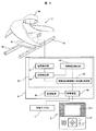
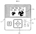
- FIG. 3 is a front view illustrating the configuration of a remote controller that is an output unit according to the first embodiment.
- FIG. 9 The front view explaining the other example of the remote control shown in FIG.
- 9 is a flowchart for explaining a fan abnormality detection flow according to the second embodiment.
- the outdoor unit of the air conditioner according to the present invention is particularly characterized by abnormality detection of an outdoor unit fan and display of an abnormal level. Note that, in each drawing, the portions denoted by the same reference numerals indicate the same or corresponding portions.
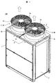
- FIGS. 1 is a perspective view showing Embodiment 1 of an outdoor unit of an air conditioner of the present invention
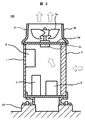
- FIG. 2 is a cross-sectional view taken along the line II-II in FIG. 1, and
- FIG. It is a figure explaining the structure to detect.
- an outdoor unit 100 installed on an outdoor foundation (or mount) 20 and one or more indoor units (not shown) installed indoors are connected by a refrigerant pipe to form a refrigeration cycle.
- the air conditioning is performed.
- the outdoor unit 100 includes an air-cooled heat exchanger 2 and a blower 3 (3 ⁇ / b> A, 3 ⁇ / b> B) for ventilating the heat exchanger 2. Yes.
- two fans 3A and 3B are provided.
- the blowers 3A and 3B are respectively provided with a fan (propeller fan) 3a, a shroud 3b that functions as a bell mouth or a duct, a motor (fan motor) 3c that drives the fan 3a, and this motor.
- the motor support member 3d that supports 3c and the fan guard 3e are configured.
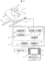
- a compressor 4, an accumulator 5, a control product box 6, and the like are provided inside the housing 1.
- Information from various sensors such as an outside air temperature sensor and a pressure sensor of a refrigeration cycle constituting the air conditioner is input into the control product box 6, and the compressor 4 and the expansion valve (not shown). ) And the like, and a control device for controlling the refrigeration cycle components, an inverter device for controlling the blower 3, and the like are housed.
- control product box 6 while driving a motor (fan motor) 3c of the blower 3, an inverter device 6a for controlling the motor 3c to a desired rotational speed, A control device 6b for controlling the refrigeration cycle 7 having the compressor 10, the expansion valve, the various sensors, and the like is provided.
- the inverter device 6a is provided with a current detector 61 for detecting a drive current (motor current) for driving the fan 3a and a phase detector 62 for detecting the magnetic pole position of the motor 3c. Further, the inverter device 6a extracts a q-axis current pulsation (pulsation current) having a period synchronized with the rotation period obtained from the phase detection unit 62 with respect to the current detected by the current detection unit.
- a pulsating current detector 63 is provided.
- the inverter device 6a is also provided with a calculation unit 64 that determines an abnormality of the fan 3a from the pulsating current detected by the pulsating current detection unit 63 and the rotational speed of the fan.
- the calculation unit 64 multiplies the amplitude value of the pulsating current (pulsating current amplitude value) by the rotation speed of the fan, and determines the abnormality of the fan 3a from the multiplied value. ing.
- the calculation unit 64 not only uses a calculated value obtained by multiplying the pulsating current amplitude value by the fan speed, but also a calculated value obtained by multiplying the pulsating current value (for example, the maximum value of the pulsating current) by the fan speed.
- the abnormality of the fan 3a may be determined using
- the control device 6b is connected to the arithmetic unit of the inverter device 6a through a communication line or the like.
- the control product box 6 is provided with a storage device 6c connected to the control device 6b.
- the storage device 6c is configured to store the result of determining the abnormality of the fan 3a. Yes.
- the output unit 8 is an output unit, and in this embodiment, the output unit 8 is composed of an operation remote controller 81 for operating the air conditioner, and is connected to the control device 6b through a communication line. Therefore, in this embodiment, the result of the abnormality determination of the fan 3a in the arithmetic unit 64 is output to the operation remote controller 81 as the output unit 8 via the control device 6b, and the determination result or the like is displayed on the display unit 81a. Can be displayed.
- the past fan abnormality determination history of the fan 3a stored in the storage device 6c can be displayed on the display unit 81a of the operation remote controller 81 as an output unit via the control device 6b. It is configured to be able to.
- the vibration level of the fan 3a can be obtained from an external remote monitoring system or a personal computer. Abnormality can be grasped.
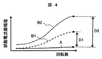
- FIG. 4 is a diagram showing the relationship between the pulsating current amplitude value and the rotational speed of the fan
- FIG. 5 is a diagram showing the relationship between the fan excitation force and the rotational speed of the fan.
- the horizontal axis represents the fan rotation speed
- the vertical axis represents the pulsating current amplitude value of the fan driving current.
- the curve indicated by A is the pulsating current amplitude value with respect to the rotational speed of the normal fan
- the broken curve indicated by B1 is the pulsating current amplitude value with respect to the rotational speed of the fan with a small unbalance
- the broken curve indicated by B2 is the large unbalanced.
- the pulsating current amplitude value with respect to the rotational speed of the fan is shown.
- D1 is a difference in amplitude value with respect to the normal fan A in the high rotation range of the fan B1 with small unbalance
- D2 is a difference in amplitude value with respect to the normal fan A in the high rotation range of the fan B2 with large unbalance.
- the pulsating current amplitude value shown in FIG. 4 increases with an increase in the rotational speed up to a certain rotational speed, but the increase in the pulsating current amplitude value becomes dull in the high rotational speed range.
- the relationship between the fan excitation force and the fan rotation speed due to the occurrence of unbalance will be described with reference to FIG.
- the horizontal axis represents the fan rotation speed
- the vertical axis represents the fan excitation force.
- the curves indicated by A, B1, and B2 are fan excitation forces with respect to the rotational speeds of the normal fan A, the small unbalanced fan B1, and the large unbalanced fan B2, respectively, as in FIG.
- the excitation force generated by the rotation of the fan is proportional to the square of the rotational speed of the fan. Further, the vibration amplitude and stress generated in the motor support member 3d and the casing 1 of the outdoor unit by the fan excitation force tend to be approximately proportional to the excitation force, and are approximately equal to the square of the fan rotation speed. Proportional. For this reason, the higher the rotation range shown in FIG. 5, the greater the influence on the vibration and stress due to fan imbalance.
- the change in the pulsating current amplitude value due to the occurrence of fan imbalance is not sufficiently correlated with the vibration amplitude and stress generated by the fan excitation force shown in FIG. .
- an index used for detecting an abnormality of the fan it is desirable to use an index having a higher correlation with the vibration amplitude and stress generated by the fan excitation force than the pulsating current amplitude value shown in FIG. That is, if a fan abnormality or vibration level is determined using an index having a higher correlation with the vibration amplitude or stress generated by the fan excitation force, the fan abnormality can be determined with high accuracy. It is possible to more reliably prevent the heat exchanger, piping, and other parts from being damaged.
- the pulsating current amplitude value obtained from the pulsating current detecting unit 63 is not used as it is for the determination of the abnormality or vibration level of the fan 3a.
- a calculation unit 64 that multiplies the fan rotation number obtained from the phase detection unit 62 (pulsation current amplitude value ⁇ rotation number) is provided, and the calculation result (calculated value) in the calculation unit 64 is used to control the air conditioner.
- the abnormality determination of the fan 3a or the determination of a vibration level is implemented by handing over to the integrated control apparatus 6b.
- the calculation unit 64 in the inverter device 6a is not limited to the abnormality determination of the fan 3a or the determination of the vibration level.
- the function of the calculation unit 64 is not limited to the control device 6b. You may make it have the calculating part provided in the inside.
- the calculation unit 64 calculates “pulsation current amplitude value ⁇ rotation speed”.
- the characteristics of the calculated value will be described with reference to FIG.
- FIG. 6 is a diagram showing the relationship between the product of the pulsating current amplitude value and the fan rotational speed, and the fan rotational speed.
- the horizontal axis represents the fan rotation speed
- the vertical axis represents the calculated value of “pulsation current amplitude value ⁇ rotation speed”.
- the curve indicated by A is the calculated value for the rotation speed of the normal fan
- the broken curve indicated by B is an unbalanced fan.
- the calculated value of “pulsation current amplitude value ⁇ rotation speed” with respect to the rotation speed of the fan is closer to the relationship of the fan excitation force with respect to the rotation speed described above with reference to FIG.
- the difference D1 ′ in the calculated value shown in FIG. 6 is much larger than the difference D1 in amplitude value from the normal fan A in the high rotation range of the small unbalanced fan B1 shown.
- the present embodiment it is possible to determine the abnormality of the fan 3a or the determination of the vibration level with higher accuracy, and the heat exchanger 2, the piping, and other parts of the outdoor unit 100 are damaged. Can be more reliably prevented.
- 3 is displayed on the display unit 81a of the output unit 8 shown in FIG. 3.
- the determination result such as fan abnormality in the calculation unit 64 shown in FIG. 3 or the calculation unit of the control device 6b is displayed.
- the vibration level can be determined from an early stage where the rotation speed is low and the vibration level is small, and can be notified to the display unit 81a, etc., so that preventive maintenance such as damage to the outdoor unit can be reliably performed. Is obtained.
- the abnormality and the vibration level are determined by an index highly correlated with the vibration amplitude and stress generated in the motor support member 3d and the casing 1 of the outdoor unit due to the excitation force due to the unbalance of the fan. Highly accurate determination is possible. As a result, if the vibration level is below a certain level, the operation is continued, and if the vibration level is above a certain level, the outdoor unit can be operated efficiently, and the outdoor unit can be prevented from being seriously damaged.
- the abnormality detection includes not only the case where the fan becomes abnormal and needs to be stopped, but also the detection of the vibration level due to the occurrence of fan imbalance.
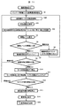
- step S1 the operation of the outdoor unit is prepared in accordance with the operation start command received from the indoor operation remote controller 81 or the like.
- step S2 the operation of the blower 3 of the outdoor unit by the inverter device 6a is started.
- step S2 the drive current (motor current) of the motor 3c of the blower 3 is detected by the current detection unit (current sensor) 61 of the inverter device 6a.
- the pulsating current detector 63 calculates the amplitude value of the current pulsation. That is, a component synchronized with the rotation period of the fan 3a is extracted from the current value detected by the current detector 61, and the pulsating current amplitude value is calculated.
- step S4 the calculation unit 64 calculates and calculates the product of the pulsating current amplitude value and the rotational speed of the fan 3a (pulsating current amplitude value ⁇ rotational speed) and calculates the fan 3a from this calculated value.
- the vibration level (abnormal level) is determined. For example, the vibration level is determined to be determined in six stages, the relationship between the calculated value and the vibration level is determined in advance, and the vibration level corresponding to the magnitude of the calculated value is determined.
- the vibration level is displayed on the display unit 81a of the output unit 8 (step S5).
- the display on the display unit 81a may be visually changed in accordance with the magnitude of the determined vibration level.
- an alarm display is performed.
- the first threshold value is the vibration level 3 and the determined vibration level is 3 or more, an alarm is displayed on the display unit 81a or the like.
- the output unit 8 is an operation remote controller 81 for operating the indoor unit.
- the output unit 8 is a display device on the control board of the outdoor unit 100 (this display device is composed of a 7-segment LED, a liquid crystal panel, or the like. ), A building monitoring system, a personal computer, or various communication lines, wireless LANs, devices connected via Bluetooth (registered trademark), etc. may be displayed remotely.
- step S5 the process proceeds to step S6, where a second threshold value set in advance for determining abnormality of the fan 3a is compared with the determined vibration level.
- the second threshold value is larger than the first threshold value, for example, a vibration level of 5 or higher. If the vibration level is lower than the second threshold, it is determined that the vibration level is within the normal level, the abnormal condition duration timer is reset (step S9), and the process returns to step S2. In step S9, not only the duration timer is reset, but also the number of retries described later is reset.
- step S6 if the vibration level is equal to or higher than the second threshold, the abnormal condition duration timer is counted up (step 7).
- step S8 the value of the duration timer is compared with a third threshold value that is a predetermined duration time, and the duration time at which the vibration level is equal to or greater than the second threshold value is less than the third threshold value. If there is, the process returns to step S2.
- step S10 If the value of the duration timer is equal to or greater than the third threshold value, it is determined that there is a possibility of abnormality, and the rotation speed of the motor 3c of the blower is reduced or stopped (step S10). Thereafter, after the elapse of a predetermined time (for example, 10 to 20 seconds), the rotational speed of the motor 3c is increased or restarted, and the number of retries is counted up (step S11).
- a predetermined time for example, 10 to 20 seconds
- steps S10 and S11 are a retry operation of increasing the speed of the fan 3a after decelerating or restarting the fan 3a after stopping.
- a true abnormality such as a defect is not generated in the fan 3a, but when a foreign object is temporarily attached, the foreign object is peeled off. This operation is performed in the hope that it will be removed.
- the higher acceleration / deceleration has a greater effect of peeling off the adhered foreign matter with inertial force. Is effective.
- the fan is rapidly decelerated at a deceleration of 6 rotations / s 2 or more, or 6 rotations / s 2. It is preferable to accelerate rapidly with the above acceleration.
- the retry operation is an operation of rotating the fan 3a in the reverse direction (reverse rotation) and then rotating the fan in the normal direction (forward rotation).
- the retry operation is repeated at least once or twice or more during one retry operation in steps S10 to S11.
- the time between the steps S10 to S11 is a short time, for example, less than 1 minute, it is preferable to perform the retry operation while the compressor 4 is operating.
- the comfort of the air conditioner decreases, so it is better to continue the operation of the compressor even during the retry operation.
- step S12 the number of retries is set in advance. Compared with the determined fourth threshold value, if it is less than the fourth threshold value, the process returns to step S2 again to continue the operation.
- the retry count is reset in step S9.
- step S12 If the number of retries exceeds the fourth threshold value in step S12, it is determined that the abnormality of the fan 3a cannot be recovered by the retry operation, and the process proceeds to step S13.
- step S13 the operation of the outdoor unit having the fan 3a that has detected the abnormality is stopped. Therefore, when there is only one outdoor unit, the air conditioner stops.
- step S13 In the case of an outdoor unit multi-connection structure in which a plurality of outdoor units are multi-connected to the same refrigeration cycle system, in step S13, only the outdoor unit having the fan 3a in which an abnormality is detected is stopped and the same refrigeration is performed. Continue operation for other normal outdoor units connected to the cycle system. At this time, the operating load information such as the compressor operating frequency of the outdoor unit that has been stopped by detecting an abnormality is handed over to other normal outdoor units, and the compressor operating frequency of the normal outdoor unit is fed to an appropriate frequency. Pull up with forward control.
- control device 6b includes the operation load information of the stopped outdoor unit so as to cover the load borne by the stopped outdoor unit as much as possible with a normal outdoor unit that continues operation. Control normal outdoor unit.
- control device 6b distributes the operating load of the stopped outdoor units to the normal outdoor units, and each normal outdoor unit Increase the compressor operating frequency to an appropriate frequency.
- step S13 When the operation of the outdoor unit having the fan 3a in which the abnormality is detected is stopped in step S13, the process proceeds to step 14 where the abnormality detection result is output to the output unit 8 and the display unit 81a is abnormally stopped. Display. Thereby, it becomes possible to perform the restoration
- the outdoor unit installation location, model, serial number, connection system, unit number, degree of abnormality (vibration level or abnormal level), etc., which has been stopped due to an abnormality in the fan 3a are output to the output unit 8 and displayed. It is good to display on the part 81a.
- the abnormal stop history is also recorded in the storage device 6c connected to the control device 6b shown in FIG. 3 (step S15).
- the storage device 6c may be configured by an SSD, HD, SD card, CF card, or the like in addition to the EEPROM.
- the storage device 6c can store a plurality of abnormality detection results, and can store a past abnormality determination history of the fan and an operation status log for a predetermined time before the abnormality detection. It is configured to be able to output the abnormality determination history and so on.
- the first to fourth threshold values are stored in advance in the control device 6b provided on the control board of the outdoor unit 100 or the like.
- FIG. 8 is a front view illustrating the configuration of the operation remote controller 81 which is the output unit 8 in the first embodiment.
- the display unit 81a of the operation remote controller 81 has “vibration level 1” and “vibration level 5” for the fan 1 corresponding to the blower 3A and the fan 2 corresponding to the blower 3B shown in FIG.
- the vibration level is also displayed as a bar length so that it can be clearly understood which of the six levels the vibration level of each fan is.
- the display unit 81a also displays the name and code (individual number) for identifying the outdoor unit such as “4 system No. 1 unit” so that the outdoor unit can be identified.
- the outside air temperature is also displayed (-2 °).
- the vibration level of the fan of another outdoor unit when it is desired to display the vibration level of the fan of another outdoor unit, it can be performed by operating the operation button 81b.
- the display unit 81a normally displays the indoor temperature, the set temperature, and the like, but when switching to display the vibration level of the fan of the outdoor unit, it can be performed by the menu button 81c.
- the vibration level of a fan of a certain outdoor unit becomes an abnormal level during normal display, the individual number of the abnormal outdoor unit may be displayed on the display unit 81a.
- the vibration level is displayed in 6 levels, but it is preferable that at least 4 levels or more can be displayed.
- the magnitude of vibration may be displayed as a numerical value related to the calculated value of “pulsating current amplitude value ⁇ rotation speed” instead of or in combination with the step display.
- the user or serviceman can easily recognize the vibration level of the fan even at a vibration level that does not cause an abnormal stop (abnormal level). This makes it easier to carry out preventive inspections and can prevent the outdoor unit from being damaged.
- FIG. 9 is a front view showing another display example with respect to the display example on the display unit 81a of the output unit 8 shown in FIG.
- the same reference numerals as those in FIG. 8 denote the same or corresponding parts, and differences from FIG. 8 will be described.
- the display method of the display unit 81a is different.
- the display of the vibration level in the display unit 81a shown in FIG. 9 is not a bar display or a numerical display, but an icon that abstracts a missing fan and an icon that abstracts a normal fan. It is.
- the FAN 1 corresponding to the blower 3A shown in FIG. 1 is displayed with an icon that abstracts the defect of the fan, indicating that it is abnormal.
- the magnitude of the vibration level is displayed step by step by displaying the size of the defect (white portion of the fan) step by step.
- FAN2 corresponding to the blower 3B is displayed with an icon that abstracts a normal fan, and indicates that the vibration level is small and normal. As described above, even if the vibration level is displayed with an icon that abstracts the fan, the user and the service person can easily recognize the vibration level of the fan, so that the outdoor unit can be prevented from being damaged. .
- the display unit 81 a of the output unit 8 visually determines which vibration level the vibration level corresponds to among the multi-level vibration levels.
- the vibration level obtained by the calculation unit 64 can be visually recognized as to which of the multi-level vibration levels corresponds to the vibration level.
- the information is displayed on the display unit 81a. Therefore, it is possible to easily grasp and recognize the vibration level of the fan, and to effectively prevent the outdoor unit from being damaged.
- the display unit 81a displays the vibration level (abnormal level) in the above-described bar display, display with numerical values and characters, display with an icon abstracting a fan, graph bar, graphic, symbol, etc. May be displayed visually recognizable.
- the calculation unit 64 calculates the product of the pulsating current amplitude value and the fan rotational speed (pulsating current amplitude value ⁇ rotational speed), and the vibration level of the fan from the calculated value. Is determined.
- the calculation unit 64 has the pulsation amplitude value of the fan drive current, that is, the product of the pulsation current amplitude value and the value obtained by squaring the fan rotation speed (pulsation current amplitude value ⁇ (fan rotation 2 ) and the vibration level of the fan is determined from the calculated value.
- the fan vibration level can be determined. That is, the calculated value of “pulsation current amplitude value ⁇ (rotation speed) 2 ” is approximated by the fan excitation force with respect to the fan rotation speed shown in FIG. This has the effect of accurately detecting the vibration level of the fan from the rotational speed stage.
- the pulsating current of the component synchronized with the rotation of the fan is extracted from the current value detected by the current detecting unit 61 provided in the inverter device 6a. Since the fan abnormality is determined from the fan rotation speed, the fan abnormality can be detected at low cost and from a low fan rotation speed without adding any additional parts to the outdoor unit 100. Is obtained.
- a display unit for visually displaying which of the multi-level vibration levels the vibration level corresponds to, and the level of the vibration level obtained by the calculation unit is multi-stage Since it has an output part that displays on the display part so that it can be visually recognized which vibration level corresponds to the vibration level, it is possible to easily grasp fan abnormality from a mild stage There is an effect that the outdoor unit 100 can be prevented from being damaged.
- FIG. 10 is a diagram for explaining a configuration for detecting fan abnormality in the second embodiment of the present invention
- FIG. 11 is a flowchart for explaining fan abnormality detection in the second embodiment. 10 and 11, the portions denoted by the same reference numerals as those in FIGS. 1 to 9 are the same or corresponding portions, and the description will be focused on the points different from the first embodiment, and the description of the same portions will be omitted.
- the pulsating current of the component synchronized with the rotation of the fan is extracted from the current value detected by the current detection unit 61 provided in the inverter device 6a as the vibration detection means of the fan 3a.
- An example of detecting fan vibration has been described.
- a gyro sensor angular acceleration sensor
- 9 is a gyro sensor, and this gyro sensor 9 is attached to the motor support member 3d which supports the motor 3c of the fan 3a.
- the mounting position of the gyro sensor 9 on the motor support member 3d is more angular on the end side of the motor support member 3d away from the position where the motor 3c is mounted. Acceleration can be detected with higher accuracy.
- the angular acceleration information detected by the gyro sensor 9 is input to the angular acceleration filter circuit 65.
- the angular acceleration filter circuit 65 uses the rotation speed signal obtained from the phase detection unit 62 of the inverter device 6a and uses the fan rotation speed frequency. Apply a component bandpass filter. Thereby, the influence of disturbances other than the fan 3a is excluded.
- the angular acceleration information after being filtered by the angular acceleration filter circuit 65 is sent to an integration circuit 66, where it is integrated to determine the deflection angle of the motor support member 3d. Therefore, the magnitude (vibration level) of the vibration by the fan 3a can be determined by the integrated value obtained by the integrating circuit 66.
- the integrated value obtained by the integration circuit 66 is transferred to the control device 6b, which determines the vibration level of the fan 3a and displays it on the display unit 81a of the output unit 8.
- Other configurations are the same as those of the first embodiment.
- steps S1 and S5 to S15 are the same as those described in FIG. 7, so the description of the same parts is omitted, and steps S20 to S22 different from FIG. 7 will be mainly described.
- step S1 after the operation start command, the operation of the blower 3 of the outdoor unit by the inverter device 6a is started (step S1). Next, it moves to step S20 and the rotation speed of the motor 3c of the air blower 3 is detected from the phase detector 62 of the inverter device 6a.
- step S21 angular acceleration is detected by the gyro sensor 9, and this angular acceleration signal is input to the angular acceleration filter circuit 65.
- step S22 the angular acceleration filter circuit 65 uses the angular acceleration signal and the rotational speed signal obtained from the phase detector 62, and uses the band speed of the fan rotational frequency component in the angular acceleration signal. Filter and obtain post-filter angular acceleration information.
- the obtained signal of angular acceleration information is input to the integration circuit 66, and the integration circuit 66 integrates the angular acceleration after the filter to calculate the deflection angle of the motor support member 3d. From the calculated value, the vibration level (abnormal level) of the fan 3a is determined.
- the determined vibration level is displayed on the display unit 81a of the output unit 8 (step S5).
- the following flow is the same as that described with reference to FIG. 7, but the process returns to step S20 after the process of step S9. Also in steps S8 and S12, the process returns to step S20 when the value is less than the threshold value.
- the angular acceleration detected by the gyro sensor is used, and this is integrated to calculate the deflection angle, and the vibration level is determined.
- the effect of detecting the vibration (fan abnormality at a low rotational speed) with higher accuracy can be obtained.
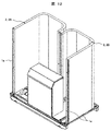
- FIG. 12 is a perspective view illustrating a configuration example of the heat exchanger of the outdoor unit according to the third embodiment of the present invention.
- the third embodiment is implemented in combination with the first or second embodiment described above.
- the fan that has detected the abnormality is It is preferable to stop only the blower that has it and continue the operation for the remaining blowers.
- FIG. 12 shows the configuration of the heat exchanger inside the casing of FIG. 1, and when the heat exchanger 2 is divided into a plurality of left and right heat exchangers 2A and 2B inside the casing, a fan that has detected an abnormality
- the blower having the above for example, the blower 2A is stopped, the velocity distribution of the air passing through the heat exchanger 2A and the heat exchanger 2B is different.
- the amount of air that is ventilated to the heat exchanger 2A is significantly smaller than the amount of air that flows to the heat exchanger 2B.
- an expansion valve (not shown) is provided in each refrigerant pipe of the left and right heat exchangers 2A, 2B, and each expansion valve can be controlled independently. For example, when it is detected that an abnormality has occurred in the fan of one blower 3A, the blower 3A having this fan is stopped, and the other normal blower 3B is continuously operated.
- the expansion valves are controlled so that the refrigerant flows. That is, the expansion valve opening degree on the heat exchanger 2A side corresponding to the stopped blower 3A is controlled to be smaller than the expansion valve opening degree on the heat exchanger 2B side corresponding to the fan 3B during operation.
- the expansion valve is controlled by the control device 6b.
- 1a is the flame
- the retry control is performed so that the retry operation for changing the rotation of the fan is performed at least once. Therefore, it is possible to reduce the erroneous determination of the fan abnormality of the outdoor unit and improve the accuracy of abnormality detection. That is, in this embodiment, when a fan abnormality is detected, a recovery operation called a retry operation is performed, and if the imbalance is due to a temporary factor, the factor can be eliminated. Accordingly, it is possible to perform fan abnormality detection with improved accuracy while suppressing erroneous detection of fan abnormality.
- an inverter device that controls the rotation speed of the fan is provided, and the pulsating current is extracted and detected from the current value detected by the current detection unit provided in the inverter device, and the pulsating current and the rotation of the fan are detected.
- the number of fan vibrations is detected from the number to determine the possibility of fan abnormality. Therefore, the abnormality of the fan of the outdoor unit can be detected with almost no additional components added to the outdoor unit housing, and the abnormality can be detected at a low cost and from a state where the rotational speed of the fan is low.
- this invention is not limited to the Example mentioned above, Various modifications are included. Further, a part of the configuration of one embodiment can be replaced with the configuration of another embodiment, and the configuration of another embodiment can be added to the configuration of one embodiment. Further, the above-described embodiments have been described in detail for easy understanding of the present invention, and are not necessarily limited to those having all the configurations described.
- SYMBOLS 1 Housing, 1a ... Frame, 2 (2A, 2B) ... Heat exchanger, 3 (3A, 3B) ... Blower, 3a ... Fan, 3b ... Shroud, 3c ... Motor, 3d ... Motor support member, 3e ... Fan Guard, 4 ... Compressor, 5 ... Accumulator, 6 ... Control box, 6a ... Inverter device, 6b ... Control device, 6c ... Storage device, 61 ... Current detection unit, 62 ... Phase detection unit, 63 ... Pulsation current amplitude value Detection unit, 64 ... arithmetic unit, 65 ... angular acceleration filter circuit, 66 ... integration circuit, 7 ...
- refrigeration cycle 8 ... output unit, 81 ... operation remote control, 81a ... display unit, 9 ... gyro sensor, 100 ... outdoor unit, A ... normal fan, B ... unbalanced fan, B1 ... small unbalanced fan, B2 ... unbalanced large fan.
Landscapes
- Engineering & Computer Science (AREA)
- Mechanical Engineering (AREA)
- General Engineering & Computer Science (AREA)
- Chemical & Material Sciences (AREA)
- Combustion & Propulsion (AREA)
- Physics & Mathematics (AREA)
- Fluid Mechanics (AREA)
- Air Conditioning Control Device (AREA)
- Control Of Positive-Displacement Air Blowers (AREA)
Priority Applications (1)
| Application Number | Priority Date | Filing Date | Title |
|---|---|---|---|
| CN201680084315.6A CN108885018B (zh) | 2016-03-31 | 2016-12-22 | 空气调节装置的室外机 |
Applications Claiming Priority (2)
| Application Number | Priority Date | Filing Date | Title |
|---|---|---|---|
| JP2016-072370 | 2016-03-31 | ||
| JP2016072370A JP6395752B2 (ja) | 2016-03-31 | 2016-03-31 | 空気調和装置の室外機 |
Publications (1)
| Publication Number | Publication Date |
|---|---|
| WO2017168887A1 true WO2017168887A1 (ja) | 2017-10-05 |
Family
ID=59962939
Family Applications (1)
| Application Number | Title | Priority Date | Filing Date |
|---|---|---|---|
| PCT/JP2016/088429 WO2017168887A1 (ja) | 2016-03-31 | 2016-12-22 | 空気調和装置の室外機 |
Country Status (3)
| Country | Link |
|---|---|
| JP (1) | JP6395752B2 (zh) |
| CN (1) | CN108885018B (zh) |
| WO (1) | WO2017168887A1 (zh) |
Cited By (2)
| Publication number | Priority date | Publication date | Assignee | Title |
|---|---|---|---|---|
| US10684054B2 (en) * | 2017-05-22 | 2020-06-16 | Trane International Inc. | Tension support system for motorized fan |
| CN113623258A (zh) * | 2021-08-26 | 2021-11-09 | 广东电网有限责任公司 | 一种风向检测装置 |
Families Citing this family (9)
| Publication number | Priority date | Publication date | Assignee | Title |
|---|---|---|---|---|
| CN109372771A (zh) * | 2018-10-31 | 2019-02-22 | 宁波兴泰科技有限公司 | 一种用于吊扇保护的系统 |
| CN109945395B (zh) * | 2019-03-21 | 2021-02-26 | 广东美的制冷设备有限公司 | 检测方法、空调系统及介质 |
| CN110160168B (zh) * | 2019-05-08 | 2020-09-25 | 青岛海尔空调器有限总公司 | 空调器 |
| JP6670970B1 (ja) * | 2019-06-26 | 2020-03-25 | 日立ジョンソンコントロールズ空調株式会社 | 空気調和機 |
| JP7390122B2 (ja) * | 2019-07-18 | 2023-12-01 | 日立ジョンソンコントロールズ空調株式会社 | 空気調和システム及び異常検出システム |
| JP7356832B2 (ja) * | 2019-07-18 | 2023-10-05 | 日立ジョンソンコントロールズ空調株式会社 | 空気調和システム及び異常検出システム |
| JP6956150B2 (ja) * | 2019-08-09 | 2021-10-27 | 日立ジョンソンコントロールズ空調株式会社 | 冷凍サイクルシステム |
| CN110674700B (zh) * | 2019-08-31 | 2023-07-21 | 深圳市广宁股份有限公司 | 基于数字孪生模型的电子设备的智能健康预测方法及装置 |
| CN111779702B (zh) * | 2020-06-30 | 2022-03-01 | 中车青岛四方机车车辆股份有限公司 | 一种卡滞故障处理方法及装置 |
Citations (6)
| Publication number | Priority date | Publication date | Assignee | Title |
|---|---|---|---|---|
| JP2006090677A (ja) * | 2004-09-27 | 2006-04-06 | Mitsubishi Electric Corp | 空気調和機の制御装置 |
| JP2007198653A (ja) * | 2006-01-25 | 2007-08-09 | Kansai Electric Power Co Inc:The | 環境制御装置及びその動作プログラム |
| JP2008232562A (ja) * | 2007-03-22 | 2008-10-02 | Daikin Ind Ltd | 空調システム |
| JP2010065594A (ja) * | 2008-09-10 | 2010-03-25 | Mitsubishi Electric Corp | 電動送風機の故障診断装置及びそれを搭載した電気機器 |
| JP2010121869A (ja) * | 2008-11-20 | 2010-06-03 | Daikin Ind Ltd | 室内機及び空気調和機 |
| JP2014137161A (ja) * | 2013-01-15 | 2014-07-28 | Daikin Ind Ltd | 空気調和装置 |
Family Cites Families (2)
| Publication number | Priority date | Publication date | Assignee | Title |
|---|---|---|---|---|
| JP6126970B2 (ja) * | 2013-10-21 | 2017-05-10 | ジョンソンコントロールズ ヒタチ エア コンディショニング テクノロジー(ホンコン)リミテッド | 空気調和機 |
| CN203980512U (zh) * | 2014-06-16 | 2014-12-03 | 广东美的集团芜湖制冷设备有限公司 | 用于安装空调室外机的安装支架 |
-
2016
- 2016-03-31 JP JP2016072370A patent/JP6395752B2/ja active Active
- 2016-12-22 WO PCT/JP2016/088429 patent/WO2017168887A1/ja active Application Filing
- 2016-12-22 CN CN201680084315.6A patent/CN108885018B/zh active Active
Patent Citations (6)
| Publication number | Priority date | Publication date | Assignee | Title |
|---|---|---|---|---|
| JP2006090677A (ja) * | 2004-09-27 | 2006-04-06 | Mitsubishi Electric Corp | 空気調和機の制御装置 |
| JP2007198653A (ja) * | 2006-01-25 | 2007-08-09 | Kansai Electric Power Co Inc:The | 環境制御装置及びその動作プログラム |
| JP2008232562A (ja) * | 2007-03-22 | 2008-10-02 | Daikin Ind Ltd | 空調システム |
| JP2010065594A (ja) * | 2008-09-10 | 2010-03-25 | Mitsubishi Electric Corp | 電動送風機の故障診断装置及びそれを搭載した電気機器 |
| JP2010121869A (ja) * | 2008-11-20 | 2010-06-03 | Daikin Ind Ltd | 室内機及び空気調和機 |
| JP2014137161A (ja) * | 2013-01-15 | 2014-07-28 | Daikin Ind Ltd | 空気調和装置 |
Cited By (3)
| Publication number | Priority date | Publication date | Assignee | Title |
|---|---|---|---|---|
| US10684054B2 (en) * | 2017-05-22 | 2020-06-16 | Trane International Inc. | Tension support system for motorized fan |
| CN113623258A (zh) * | 2021-08-26 | 2021-11-09 | 广东电网有限责任公司 | 一种风向检测装置 |
| CN113623258B (zh) * | 2021-08-26 | 2022-07-08 | 广东电网有限责任公司 | 一种风向检测装置 |
Also Published As
| Publication number | Publication date |
|---|---|
| CN108885018A (zh) | 2018-11-23 |
| JP2017180999A (ja) | 2017-10-05 |
| JP6395752B2 (ja) | 2018-09-26 |
| CN108885018B (zh) | 2019-12-10 |
Similar Documents
| Publication | Publication Date | Title |
|---|---|---|
| JP6395752B2 (ja) | 空気調和装置の室外機 | |
| JP6339950B2 (ja) | 空気調和機の室外機 | |
| JP4265601B2 (ja) | 空気調和機 | |
| US10330099B2 (en) | HVAC compressor prognostics | |
| WO2016159152A1 (ja) | 空調室内ユニット | |
| JP6126970B2 (ja) | 空気調和機 | |
| EP2426428B1 (en) | Air-conditioning apparatus | |
| JP2010210121A (ja) | 空気調和装置 | |
| JP2011094920A (ja) | 空気調和装置 | |
| JP2017180999A5 (zh) | ||
| JP2010107058A (ja) | 空気調和機 | |
| JP2008202908A (ja) | 空気調和機 | |
| JP2006275458A (ja) | 空気調和装置 | |
| EP3054229B1 (en) | Air conditioner | |
| JP6692675B2 (ja) | 空気調和装置の室外機 | |
| JP2015222151A (ja) | 空気調和機の室外機 | |
| JP5851335B2 (ja) | 空気調和機 | |
| JP2009243800A (ja) | 空気調和機 | |
| CN112240625B (zh) | 空气调节系统以及异常检测系统 | |
| JP2014190567A (ja) | 空気調和装置の室外ユニット | |
| JP7356832B2 (ja) | 空気調和システム及び異常検出システム | |
| JP2005201461A (ja) | 空気調和装置 | |
| JP2009204194A (ja) | 設備用空気調和機の室内機 | |
| US20210041123A1 (en) | Refrigeration cycle system | |
| WO2024070209A1 (ja) | 制御装置およびプログラム |
Legal Events
| Date | Code | Title | Description |
|---|---|---|---|
| NENP | Non-entry into the national phase |
Ref country code: DE |
|
| 121 | Ep: the epo has been informed by wipo that ep was designated in this application |
Ref document number: 16897103 Country of ref document: EP Kind code of ref document: A1 |
|
| 122 | Ep: pct application non-entry in european phase |
Ref document number: 16897103 Country of ref document: EP Kind code of ref document: A1 |