WO2017168808A1 - 自動取引装置、電源供給制御方法 - Google Patents
自動取引装置、電源供給制御方法 Download PDFInfo
- Publication number
- WO2017168808A1 WO2017168808A1 PCT/JP2016/081957 JP2016081957W WO2017168808A1 WO 2017168808 A1 WO2017168808 A1 WO 2017168808A1 JP 2016081957 W JP2016081957 W JP 2016081957W WO 2017168808 A1 WO2017168808 A1 WO 2017168808A1
- Authority
- WO
- WIPO (PCT)
- Prior art keywords
- unit
- transaction
- customer
- saving mode
- energy saving
- Prior art date
- Legal status (The legal status is an assumption and is not a legal conclusion. Google has not performed a legal analysis and makes no representation as to the accuracy of the status listed.)
- Ceased
Links
Images




Classifications
-
- G—PHYSICS
- G06—COMPUTING OR CALCULATING; COUNTING
- G06F—ELECTRIC DIGITAL DATA PROCESSING
- G06F1/00—Details not covered by groups G06F3/00 - G06F13/00 and G06F21/00
- G06F1/26—Power supply means, e.g. regulation thereof
- G06F1/32—Means for saving power
-
- G—PHYSICS
- G07—CHECKING-DEVICES
- G07D—HANDLING OF COINS OR VALUABLE PAPERS, e.g. TESTING, SORTING BY DENOMINATIONS, COUNTING, DISPENSING, CHANGING OR DEPOSITING
- G07D9/00—Counting coins; Handling of coins not provided for in the other groups of this subclass
Definitions
- the present invention relates to an energy saving mode function of an automatic teller machine (ATM) used in a financial institution such as a bank.
- ATM automatic teller machine
- Patent Document 1 discloses a technology that starts recovery processing from an energy saving mode and improves customer waiting time when a sensor detects that a customer has entered the store.
- the transaction screen is displayed only when the energy saving mode return processing is performed to return from the energy saving mode to the standby state once and the device is normally in the standby state and all units can be operated. Is displayed. Therefore, until the device transitions from the energy saving mode to the standby mode, a state in which the customer is unable to make a transaction occurs and it is time to wait in front of the device. Further, when the energy saving mode returns to the standby state normally, the transaction can be started. However, when all the units do not normally enter the standby state, the transaction cannot be started after waiting. That is, the customer could not start trading until all ATM units were in standby.
- the present invention has been made in view of the above, and provides an automatic transaction apparatus and a power supply control method that do not waste a customer without waiting for a customer to start a transaction. Objective.
- an automatic transaction apparatus includes an operation unit that receives a transaction selection from a customer, and the operation unit receives an operation related to the transaction, And a control unit for returning a unit or device required for the transaction upon receipt of supply.
- the present invention can be grasped as a power supply control method performed by the automatic transaction apparatus.
- power is not consumed unnecessarily without waiting for a customer to start a transaction.
- ATM automatic teller machine
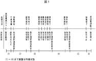
- FIG. 1 is a diagram showing the relationship between the operating time of the automatic teller machine (ATM) and the energy saving mode.
- ATM automatic teller machine
- the device in the daily operation of ATM, when the power is turned on automatically (or manually by an attendant) in the morning, the device starts up and then enters a standby state.
- the ATM enters a standby state, and if necessary, after a bill or statement slip is replenished by an attendant, it enters a standby state again. Thereafter, the ATM stands by in a standby state until the customer visits the store.
- the transaction is performed, and after the transaction is over, the system waits until the next customer comes again.
- the ATM repeats this, and when the operation end time is reached, a transaction stoppage is displayed on the customer operation panel unit (described later), and then the power is turned off when the power-off time of the installation location comes.
- FIG. 1 in the daily operation of ATM, when the power is turned on automatically (or manually by an attendant) in the morning, the device starts up and then enters a standby state.
- the ATM enters a standby state, and if necessary, after a bill or statement slip is replenished
- the financial institution may not dare to apply the energy saving mode.
- the energy saving mode even when the energy saving mode is applied, it is possible to eliminate wasteful consumption of electric power without waiting for the customer to start a transaction. Can do.
- FIG. 2 is a block diagram of the ATM 1 in this embodiment.
- the ATM 1 includes a control unit 2, a power supply unit 3, a customer operation panel unit 4, an EPP device 5, a function key device 6, a card unit 7, a statement slip printing unit 8,
- the storage unit 9, the biometric authentication device 10, and the camera device 11 are configured.
- the control unit 2 is a processing unit that controls the operation of the entire ATM. For example, the control unit 2 transmits and receives various information necessary for transactions with a host device such as a host computer and a monitoring device, and controls the operation of each unit of the ATM 1. Control.
- the power supply unit 3 supplies and stops power to the entire ATM 1 and each unit constituting the ATM 1.
- the customer operation panel unit 4 includes, for example, a touch panel and a display, and displays a transaction-related screen such as a transaction selection screen for receiving various operations for executing a transaction from a customer and a transaction result.
- the EPP device 5 is composed of, for example, a PINPAD and receives an input of a personal identification number from a customer.
- the function key device 6 is a device assigned to execute a specific function, for example, displaying a keyboard for inputting a transfer destination in a transfer transaction on the screen.
- the card unit 7 reads and inserts a customer's cash card, and reads magnetic information recorded on the cash card.
- the statement slip printing unit 8 prints the transaction execution result (for example, the deposit transaction amount and the account balance after the transaction) on the statement slip.
- storage part 9 memorize
- the biometric authentication device 10 is an apparatus for authenticating a customer with a finger vein, for example.
- the camera device 11 is a camera for detecting a customer who trades ATM1.
- each of the above units is a unit that is standardly installed in ATM 1, and each unit indicated by a dotted line, such as a journal unit, is a unit that is appropriately selected and mounted as an option.
- the unit mounted as standard or the unit mounted as an option can be arbitrarily determined in consideration of the needs of the financial institution where the ATM 1 is installed.
- the power of each unit or device other than the control unit 2, the power supply unit 3, the customer operation panel unit 4, the EPP device 5, the function key 6, and the card unit 7 is turned off.
- the control unit 2 the power supply unit 3, and the customer operation panel unit 4, the other units and devices are turned off. May be. That is, as will be described later, it is sufficient that power is supplied to a unit that enables a transaction selection screen to be displayed on the customer operation panel unit 4 in a standby state.
- the control unit 2 in the apparatus has a function of starting / stopping power supply to each unit or device, and controls the start / stop of power supply to these units or devices.
- the control unit 2 puts the device in a standby state to shift to the energy saving mode, and then returns from the energy saving mode when the customer visits the store.
- Such control is an energy saving mode function.
- An advantage of applying the energy saving mode function is that power consumption during standby can be reduced in an ATM where a customer is not present for a long time. As mentioned above, the customer visits the store to turn on the power of each unit and perform the return process from the energy-saving mode, so the problem is that the customer waits until returning from the energy-saving mode. Therefore, these problems can be solved.
- FIG. 3 is a flowchart showing a processing procedure of processing (first energy saving mode processing) for controlling the power supply to each unit or device so as not to wait for a customer to start a transaction.
- first energy saving mode processing for controlling the power supply to each unit or device so as not to wait for a customer to start a transaction.
- deposit transaction is described, but other transactions can be considered in the same manner.
- the customer comes to the store while the ATM 1 is standing by in the energy saving mode X, and the customer input unit of the customer operation panel unit 4 performs a transaction from the customer.
- the touch for starting is accepted (S301).
- the energy saving mode in this example means that, for example, the customer operation panel unit 4 supplies power to a unit or device that triggers a customer to start a transaction, while other units or devices In this mode, power is not supplied.
- the power of each unit is turned on at this time and energy-saving mode recovery processing is performed, and until all units return from energy-saving mode and become fully transactable, the message “Wait for a while.” Please display a standby screen for the customer such as “Please,” and display a guide to wait for the customer.
- the control unit 2 is in the energy saving mode state with the transaction selection screen displayed on the customer input unit. Therefore, when a customer comes to the store and touches ATM1, it is possible to select a transaction (for example, a deposit transaction) from the transaction selection screen, and the customer input unit can accept the selection of the transaction. That is, unlike the prior art, the standby screen is not displayed to wait for the customer to return from the energy saving mode.
- control unit 2 is a unit other than the control unit unit 2, the power supply unit 3, the customer operation panel unit 4, the EPP device 5, the function key 6, and the card unit 7. Is turned on, and the energy saving mode return process is started (steps S302, S303, S304).
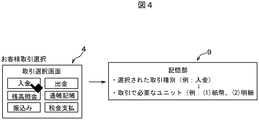
- the control unit 2 receives a selection of a transaction (for example, a deposit transaction) from among the transactions displayed on the transaction selection screen by the customer input unit of the customer operation panel unit 4. (Step S305), at the timing, information that associates the type of the selected transaction with the unit necessary for the transaction of the type is stored in the storage unit 9 (Steps S306 and S307). Since the associated information is stored in advance in the storage unit 9 for each transaction type, the control unit 2 uses the selected transaction type as a key to store the association stored in the storage unit 9. The information associated with the type being executed may be read out from the information.
- a selection of a transaction for example, a deposit transaction
- the customer selects a deposit transaction from the transaction selection screen, and the associated information includes a transaction type (payment transaction) and a unit or device (banknote deposit / withdrawal unit required for the transaction type transaction). , The statement slip printing unit) and the order of units to be started and stopped in order to execute the transaction of the transaction type.
- the control unit 2 displays a transaction screen for executing the selected type of transaction on the customer input unit (step S308).
- control unit 2 starts processing for returning the units necessary for the transaction from the energy saving mode in the order indicated in the associated information among the units that are powered on (step S309).
- the first unit is returned from the energy saving mode (step S310).
- the process of returning the units is started, so the return process of the banknote deposit / withdrawal unit as the first unit is executed.
- step S308 ends, the customer input unit accepts input and operation of information necessary for executing a transaction from the customer (step S311), and when the control unit 2 detects the input and operation (step S312). Then, it is confirmed whether or not the input contents of the information are correct, and a confirmation screen for prompting the customer to confirm is displayed on the customer input unit (step S313).
- the control unit 2 detects that the confirmation (OK) indicating that the input content is correct is input on the confirmation screen, the control unit 2 instructs the bill deposit / withdrawal unit to execute the process (step S314).
- the banknote deposit / withdrawal unit starts processing according to the instruction from the control unit 2 (step S315), and opens the shutter (step S316).
- steps S315 and S316 since the banknote deposit / withdrawal unit has already returned from the energy saving mode in step S310, processing can be started as soon as support is received from the control unit 2. That is, in steps S311, S312, and S313, the bill deposit / withdrawal unit returns from the energy saving mode while the transaction screen or confirmation is being operated from the customer. Therefore, there is no waiting time for returning to the customer from the energy saving mode.
- step S316 When the shutter is opened in step S316, the bill deposit / withdrawal unit accepts bill insertion (step S317).
- the control unit 2 refers to the associated information and returns the next unit from the energy saving mode (step S318).
- the return processing of the statement slip printing unit which is the next unit is executed, The energy saving mode return is completed before the unit operation.
- control unit 2 when the control unit 2 detects that a predetermined time has elapsed from the opening of the shutter, the control unit 2 displays a shutter closing confirmation screen for closing the shutter after the insertion of banknotes is completed on the customer input unit (step S319).
- the control unit 2 detects the input (step S321), and the banknote deposit / withdrawal unit. Is instructed to count the inserted banknotes (step S322).
- the banknote deposit / withdrawal unit starts counting the inserted banknotes according to the instruction from the control unit 2 (step S323), and executes the counting process (step S324).
- the control unit 2 determines whether or not the statement slip unit has been restored in step S318 (step S325). When it is determined that the statement slip unit has been returned (step S325; Yes), the control unit 2 receives the banknote counting result in step S323 from the banknote deposit / withdrawal unit (step S326) and inputs it to the customer input unit. A deposit amount confirmation screen for confirming the deposit amount which is the amount of the banknote is displayed (step S327).
- control unit 2 determines that the return of the statement slip unit could not be performed (step S325; No)
- the control unit 2 individually performs a recovery process on the unit and completes the return from the energy saving mode (step S328). ).
- the control unit 2 restarts by turning on the power after turning off the power of the ATM 1 itself. Since the control unit 2 stores the processing that has been completed immediately before the restart in the storage unit 9, the control unit 2 continues the processing after the restart. For example, control unit 2 may stop dealings, without restarting.
- the unit is returned from the energy saving mode before the timing of using each unit, and is operated at a necessary timing in accordance with an instruction from the control unit 2. And proceed with customer transaction processing. As a result, the customer does not feel the waiting time, and the waiting time becomes 0 seconds.
- step S327 when the customer input unit receives an input indicating that the deposit amount has been confirmed from the deposit amount confirmation screen (step S329), the control unit 2 detects the input (step S330), and the transaction is performed. It is determined that the transaction has been established, and the transaction is finalized (step S331).
- FIG. 5 is a flowchart showing the procedure of a specific determination method of the determination process in step S325.
- the control unit 2 determines whether or not a unit necessary for the transaction (for example, a statement slip unit in the deposit transaction) has returned from the energy saving mode (step S325), and has returned from the energy saving mode. If it is determined that there is no transaction (step S325; No), it is determined that the transaction has not been established (step S3251). If the control unit 2 determines that the transaction has not been established, it lowers the ATM 1 itself and shifts to the transaction stop state or restarts the unit necessary for the transaction (step S328).
- a unit necessary for the transaction for example, a statement slip unit in the deposit transaction
- control unit 2 determines that the transaction cannot be established even if the subsequent processing is continued as it is, and determines that the transaction has not been established when it is determined that the unit that should have returned has not returned. To do. Based on such determination, control is performed so as to prevent troubles in trading. Thereafter, the recovery process of the unit or apparatus is performed to bring the ATM into a normal state, and the operation of the ATM such as a transaction is resumed again.
- step S325 determines that the control unit 2 has returned from the energy saving mode (step S325; Yes).
- the control unit 2 determines that the transaction has been established (step S3252).
- the control unit 2 instructs the unit necessary for the transaction to start processing.
- step S325 for example, the control unit 2 compares the transaction type and necessary unit included in the associated information stored in step S307 with the unit that has been returned from the energy saving mode. What is necessary is just to determine whether the unit required for the process performed in this is returned from the energy saving mode.
- step S332 When the control unit 2 confirms the transaction in step S331, the control unit 2 instructs the statement slip printing unit to print (step S332).
- the statement slip printing unit starts processing according to the above instruction (step S333) and discharges the statement slip (step S334).
- step S333 When the statement slip printing unit detects that the customer has pulled out the statement slip (step S335), the control unit 2 prepares for a transaction for the next customer for the bill deposit / withdrawal unit and the statement slip printing unit.
- the post-processing execution is instructed (step S336).
- steps S337) and notify the end thereof step S338), the control unit 2 displays a transaction end screen on the customer input unit (step S339), and waits for ATM1.
- step S340 To start counting (step S340).
- control unit 2 When the control unit 2 starts timing, the control unit 2 displays a transaction selection screen on the customer input unit (step S341), and determines whether a predetermined time (for example, 1 minute) has elapsed from the timing. (Step S342). When the control unit 2 determines that the time has elapsed, the control unit 2 starts the energy saving mode (step S343), and instructs each unit that was turned on in step S304 to turn off the power (step S344). Each unit turns off the power according to the instruction received from the control unit 2 (step S345). When the process of step S345 ends, the state returns to the state of the first energy saving mode X.
- a predetermined time for example, 1 minute
- the control unit 2 of the ATM 1 selects whether or not to apply the energy saving mode function as described above, and sets the standby time for starting the energy saving mode in step S343 by the customer via the customer input unit. It may be possible. In addition, for ATMs where customer queues are generated continuously during lunch breaks, etc., the above energy-saving mode function can be set not to be applied, or transactions can be started immediately after the customer changes after the transaction ends. Thus, the setting may be appropriately changed according to the usage status of the ATM, such as setting the time setting in the standby state to be short.
- the transaction is performed while the customer is performing an operation necessary for the transaction on the transaction screen such as the transaction selection screen so that the customer does not wait until the ATM returns from the energy saving mode.
- Units and devices necessary for the system are returned from the energy-saving mode in the order of transaction execution.
- FIG. 6 is a flowchart showing a processing procedure of processing (second energy saving mode processing) for controlling the power supply to each unit or device in order to suppress wasteful power consumption.
- second energy saving mode processing for controlling the power supply to each unit or device in order to suppress wasteful power consumption.
- the ATM starts a transaction when the customer touches ATM1 in order to eliminate the waiting time of the customer as in the first energy saving mode process (steps S601 and S602). .
- the power supply to each unit or device is different from the case of the first energy-saving mode processing, and the power supply of each unit or device is individually provided at the timing required according to each transaction, not at the timing of touching ATM1. Is set to ON / OFF processing. As a result, power is consumed only at the necessary timing for only the units that require operation. Further, after the operation of the necessary unit is completed, if the unit is not used due to subsequent transaction progress, the power is turned off to reduce power consumption to save power. With the above control, processing is performed to reduce power consumption even during operation of an apparatus that has not been applied so far.
- step S602 When the process of step S602 is completed, as in the first energy saving mode process, the customer input unit of the customer operation panel unit 4 selects a transaction (for example, a deposit transaction) from among the transactions displayed on the transaction selection screen.
- the control unit 2 accepts the selection (step S603), and the control unit 2 stores, in the timing, information that associates the selected transaction type with the unit necessary for the transaction of the type in the storage unit 9 (step S604, S605).
- step S605 the control unit 2 displays a transaction screen for executing the selected type of transaction on the customer input unit (step S606), and after turning on the power of the first unit (Step S608), the return processing from the energy saving mode is started (Step S609), and the return processing is executed (Step S610).
- the bill deposit / withdrawal unit which is the first unit, is turned on, and the return process is executed.
- the customer input unit accepts input and operation of information necessary for executing a transaction from the customer (step S611), and each process similar to steps S312 to S317 of the first energy saving mode process shown in FIG. Are executed (steps S612 to S617).
- the control unit 2 displays a shutter closing confirmation screen for closing the shutter after the insertion of banknotes is completed on the customer input unit (step S618).
- the processes from step S320 to S324 are executed (steps S619 to S623).
- the statement slip printing unit which is the next unit is returned from the energy saving mode, but this process is not performed in the second energy saving mode process. Therefore, it is possible to suppress power consumption by units that are not required during this period.
- step S623 the control unit 2 receives the counting result from the banknote depositing / dispensing unit (step S624), and confirms the deposit amount that is the amount of the bills inserted into the customer input unit. A deposit amount confirmation screen is displayed (step S625).
- step S325 it is determined in step S325 whether or not the statement slip unit has been restored.
- the statement slip printing unit is powered on at this timing. Since it is not turned ON, this process is not executed and the process proceeds to the next.
- step S624 the control unit 2 displays a deposit amount confirmation screen for confirming the deposit amount, which is the amount of the inserted bill, on the customer input unit (step S625), while After turning on the power (steps S626 and S627), the return processing from the energy saving mode is started (step S628), and the return processing is executed (step S629).
- the power supply of the statement slip printing unit which is the next unit is turned on, and the return process is executed.
- the customer input unit accepts information input and operation necessary for payment confirmation from the customer (step S630), as in the first energy saving mode process, and the control unit 2 detects the input (step S631). ), It is determined that the transaction has been established, and the transaction is confirmed (step S632). Thereafter, the processes of steps S633 to S636 are executed in the same manner as the steps S332 to S335 of the first energy saving mode process.
- step S636 When the process of step S636 is completed, the control unit 2 outputs an instruction to store the counted banknotes in a storage cassette (not shown) to the banknote deposit / withdrawal unit (step S637). The bills counted according to the above are stored (steps S638 and S639).
- step S637 the control unit 2 outputs an instruction to turn off the power of the statement slip printing unit and turns off the power (steps S640 and S641), while displaying a transaction end screen on the customer input unit. (Step S642).
- step S643, S644 When the banknote storing process by the banknote depositing / withdrawing unit is completed, the control unit 2 outputs an instruction to turn off the power of the banknote depositing / withdrawing unit and turns off the power (steps S643, S644), while the transaction input is selected in the customer input unit. A screen is displayed (step S645). When the process of step S645 ends, the process returns to the initial state.
- the energy saving mode return process is executed for each unit in parallel while proceeding with the transaction process according to the customer's input and operation for the transaction selected by the customer.
- the power of each unit is turned on at the timing when each unit is required to complete the energy saving mode return. For this reason, it is necessary to execute the power ON process of the unit in the previous process for the energy saving mode return time from the timing of operating the unit used in the transaction process.
- a process for controlling the power ON / OFF of the unit is executed in conjunction with the screen.
- the screen transition flow is determined by the type of transaction selected by the customer, and the unit required for the transaction is also determined. Therefore, in FIG. 7, for example, a payment transaction, the screen necessary for that type of transaction and its display order are associated with (A), and the units and devices required for that type of transaction are associated with their activation and deactivation orders. In other words, it is stored in the storage unit 9.
- the screens 1 to 10 are displayed in this order on the customer input unit.
- the necessary units for the deposit transaction are the bill deposit / withdrawal unit and the statement slip. It is a printing unit, indicating that it is activated in this order.
- the screens 1 to 10 are not particularly described. For example, the screens are displayed during execution of a transaction such as a password input screen and a inserted bill confirmation screen.
- step S601 of the second energy saving mode process shown in FIG. 6 screen 1 (transaction selection screen) is displayed, and when a transaction is selected in step S603, the control unit 2 displays the customer input unit. Screen 2 is displayed. Thereafter, the control unit 2 displays the screen 3 when an input or operation is accepted from the customer in step S611. At this time, the control unit 2 executes step S607 as a process corresponding to the screen 3, and turns on the power of the banknote deposit / withdrawal unit which is the unit to be activated first.
- the timing at which the bill deposit / withdrawal unit is turned on is the timing at which the screen 5 is displayed.
- the control unit 2 is configured to display the screen 3 earlier than the timing to display the screen 5 by a certain grace time ⁇ in the time for returning the banknote deposit / withdrawal unit from the energy saving mode. Turn on the power.
- the control unit 2 displays the screen 4 and the screen 5 when the bill deposit / withdrawal unit is turned on together with the display of the screen 3.
- step S617 when the insertion of the banknote is accepted from the screen 5, the control unit 2 displays the screen 6 in step S619 and accepts the confirmation operation of the inserted banknote from the customer. Thereafter, the control unit 2 displays the screens 7 and 8 on the customer input unit, and then displays the screen 9 to accept input and operation of information necessary for payment confirmation.
- the control unit 2 executes step S626 as a process corresponding to the screen 9, and turns on the power of the statement slip printing unit which is a unit to be activated next.
- the timing when the statement slip printing unit is turned on is the timing when the screen 10 is displayed. However, at the timing when the screen 9 is displayed earlier than the timing when the screen 10 is displayed by the time required for returning the statement slip printing unit from the energy saving mode for a certain grace period ⁇ , the control unit 2 Turn on the power.
- step S630 when input or operation of information necessary for payment confirmation is received from the screen 9, the control unit 2 displays the screen 10 on the customer input unit. Thereafter, when the statement slip printing unit detects that the customer has extracted the statement slip, the control unit 2 displays the screen 11 on the customer input unit. At this time, the control unit 2 executes step S640 as a process corresponding to the screen 11, and turns off the power of the statement slip printing unit. Further, when the screen 11 is displayed, the control unit 2 displays the screen 1, executes step S643 as a process corresponding to the screen 1, and turns off the power of the banknote deposit and withdrawal unit.
- the control unit 2 receives the operation related to the transaction processed by the unit or device other than the unit or device necessary for the transaction (for example, in the case of the banknote deposit transaction, the control unit 2 applies to the coin deposit and withdrawal unit. Even when an operation is accepted, control is performed so that power is not supplied from the power supply unit 3 to the unit or device. For this reason, even when a customer tries to touch or operate a unit or device that is not necessary for the transaction, power is not wasted.
- the transaction will be established, and if it has not returned normally, the device will be brought down.
- the ATM may be restored by a shutdown reboot.
- the determination of transaction establishment is not affected.
- this function always functions, setting as an energy saving mode function becomes unnecessary.
- the control unit 2 receives a power supply unit for each unit or device including a unit or device necessary for a transaction constituting the ATM 1 when the customer input unit accepts the operation. Power is supplied from 3, and the necessary unit or device is returned from the energy saving mode.
- the transaction is started when the customer stands in front of the apparatus, and the transaction processing and the energy saving mode return processing are executed in parallel.
- the waiting time of the customer from the return from the energy saving mode until all the units are in the operation standby state is set to 0 seconds.
- a unit necessary for the transaction is determined from when the customer starts the transaction and the transaction is selected, and is stored as a condition for establishing the transaction. Thereby, even if all the ATM units are not completely in a normal state, if the unit necessary for the customer transaction returns from the energy saving mode, the customer transaction can be established.
- control unit 2 determines whether or not the necessary unit or device can be restored from the energy saving mode as in step S325 of FIG. 3, and the necessary unit or device can be restored from the energy saving mode. If it is determined that the process is executed by the necessary unit or device, control is performed so that useless processing does not continue even if the transaction is not completed, and useless processing is continued. It is possible to suppress the power consumption due to.
- the control unit 2 supplies power from the lower milk unit 3 to the necessary unit or device when the customer input unit accepts an operation related to the transaction, and the necessary unit. Return the unit or device from energy saving mode.
- the power of all units other than the unit necessary for displaying the transaction selection screen is turned off.
- the transaction starts when the customer stands in front of the ATM, and only the necessary units are turned on as the transaction progresses, and the transaction process and the energy saving mode return process are executed in parallel. Thereby, the waiting time of the customer is set to 0 second, and the power consumption during the ATM operation is reduced.
- a unit necessary for the transaction is determined from when the customer starts the transaction and the transaction is selected, and is stored as a condition for establishing the transaction. At this time, the screen used in the selected transaction and its display order are determined. For this reason, in order to be able to operate with respect to the unit necessary for the transaction, power is supplied in conjunction with the screen display, and the energy saving mode return process is executed. That is, the control unit 2 is based on the progress status of the transaction screen displayed on the customer input unit for the transaction and the time necessary for returning the unit or device necessary for the transaction from the energy saving mode.
- the power supply is supplied to the necessary unit or device, that is, the activation timing of the necessary unit or device is determined in consideration of the operation screen displayed when executing the ongoing transaction and the activation time of the unit or device.
- the control unit 2 is necessary for returning the unit or device required for the transaction from the energy saving mode rather than the timing for displaying the operation screen with the display order determined for executing the transaction on the customer input unit.
- Power is supplied to the unit or device necessary for the transaction at an early timing by a certain amount of time. Therefore, the necessary devices can always be returned from the energy saving mode at the timing when the customer operates from the operation screen.
- the unit is operated in transaction processing, and after the unit is operated, the power is turned off if it is unnecessary even during the transaction.
- the waiting time of the customer is set to 0 second, and the power consumption can be reduced not only during the ATM standby but also during the ATM operation. As a result, it is possible to reduce the power consumption as a whole, and to further promote the energy saving mode.
- the ATM since it is possible to reduce the power consumption during the operation of the ATM, the ATM can be operated even under environmental conditions in other countries where power supply conditions are not well established.
- the customer input unit accepts a transaction selection from the customer, and the customer input unit accepts an operation related to the transaction, while the control unit 2 receives the power supply from the power supply unit 3 and restores the unit or device necessary for the transaction, so that the customer is not required to wait to start the transaction and the power is not wasted.
- ATM Automatic teller machine
- control unit 3 power supply unit 4: customer operation panel 5: EPP device 6: function key 7: card unit 8: statement slip printing unit 9: storage unit 10: biometric authentication device 11: camera device
Landscapes
- Physics & Mathematics (AREA)
- Engineering & Computer Science (AREA)
- General Physics & Mathematics (AREA)
- Theoretical Computer Science (AREA)
- General Engineering & Computer Science (AREA)
- Power Sources (AREA)
- Financial Or Insurance-Related Operations Such As Payment And Settlement (AREA)
Abstract
顧客から取引の選択を受け付ける操作部と、操作部が取引に関する操作を受け付けつつ、電源部から電源の供給を受けて取引に必要なユニットまたはデバイスを復帰させる制御部と、を備える。
Description
本発明は、銀行等の金融機関にて使用される現金自動取引装置(ATM; Automated Teller Machine)の省エネモード機能に関するものである。
ATMも他の産業機器と同様に待機時の待機電力を低減することを推進してきた。待機電力を低減するために、ATM自身の消費電力を抑えると共に、待機時に細部への電源供給を停止することにより、不要な電力消費を抑えている。この状態で顧客の来店を待ち、顧客が来店して装置の前に立ったときに、電源供給を再開してATMを動作可能状態とする。この場合、省エネモード復帰中と表示した案内画面を操作部に表示し、省エネモードから復帰してATMが動作可能状態になった時に、初めて取引のための取引開始画面を操作部に表示して取引を行なう。これまでに特許文献1にて、顧客が入店したことをセンサが検知すると、省エネモードからの復旧処理を開始し、顧客の待ち時間を改善する技術が開示されている。
これまでのATMでは、全ユニットが即動作可能状態である場合にのみ、お客様が取引を開始することができた。そのため、装置が省エネモード状態の場合は、省エネモードから一度待機状態へと復帰をする省エネモード復帰処理を実施し、装置が正常に待機状態となり全ユニットが動作可能になった場合に初めて取引画面を表示する。そのため、装置が省エネモードから待機モードに遷移するまではお客様は取引ができない状態が発生し、装置の前で待たなければいけない時間となっている。また省エネモードから正常に待機状態へ復帰した場合は取引を開始できるが、全ユニットが正常に待機状態へならなかった場合は、待たされた後に取引を開始できない状態となる。すなわち、顧客はATMの全ユニットが待機状態となるまで取引を開始することができなかった。
また、これまではトラブルを避けるため、ATM装置の全ユニットが正常の場合にのみ取引を開始することが取引開始条件となっている。これは、お客様がどのような取引を選択しても取引が可能な状態になるように、お客様が取引を選択する前に装置として万全に準備をするためである。そのため、顧客自身の取引に関係のないユニットも即動作可能状態となっている必要があるため、装置動作時の消費電力の低減できなかった。すなわち、顧客の取引に無関係なユニットも待機状態としているため、無駄に電力を消費していた。
本発明は、上記に鑑みてなされたものであって、取引を開始するために顧客を待たせることなく、無駄に電力を消費することのない自動取引装置、電源供給制御方法を提供することを目的とする。
上記課題を解決し、目的を達成するために、本発明にかかる自動取引装置は、顧客から取引の選択を受け付ける操作部と、前記操作部が前記取引に関する操作を受け付けつつ、電源部から電源の供給を受けて前記取引に必要なユニットまたはデバイスを復帰させる制御部と、を備えることを特徴とする自動取引装置として構成される。
また、本発明は、上記自動取引装置で行われる電源供給制御方法としても把握される。
本発明によれば、取引を開始するために顧客を待たせることなく、無駄に電力を消費することがなくなる。
以下、本発明の第一の実施形態について図面を使用しながら詳細に説明する。図1は、現金自動取引装置(ATM)の動作時間と省エネモードとの関係を示す図である。
図1に示すように、ATMの一日の動作は、朝、自動(または係員による手動)で電源が入れられると、装置が起動し、その後待機状態となる。ATMが待機状態になり、必要であれば、紙幣や明細票が係員により補充された後、再び待機状態となる。その後、ATMは、待機状態のまま、顧客が来店するまでは待機する。顧客が来店すると、取引を行い、取引終了後は、また次の顧客が来るまでは待機状態となる。ATMは、これを繰り返し、稼動終了時間になれば顧客操作パネルユニット(後述)に取引中止を表示し、その後、設置場所の電源OFF時間が到来すると、電源がOFFされる。図1では、自動電源ONから行員準備まで(1)、稼動開始時の取引選択画面表示から顧客操作による取引開始まで(2)、顧客との取引終了後の取引選択画面表示から次の顧客操作による取引開始まで(3)、次の顧客との取引終了後の取引選択画面表示からさらに次の顧客操作による取引開始まで(4)、さらに次の顧客との取引終了後の取引選択画面表示から稼動終了による取扱中止まで(5)、取扱中止から装置停止まで(6)、の6つの場面で待機状態となっていることを示している。
従来、上記待機状態では、顧客がいつ来店しても即取引が可能なように、ATMを構成するすべてのユニットやデバイスを動作可能な状態で待機していた。そのため、一日のほとんどを待機状態で過ごしたとしても一定の電力を消費していた。このような待機時の消費電力を低減するために、待機時に不要なユニットやデバイスの電源をOFFする省エネモードという機能をサポートし、消費電力の低減を図るようにした。そのため省エネモードでは、顧客来店時に各ユニットやデバイスの電源をON状態とする。全ユニットやデバイスが、エラーなく省エネモードから復帰した場合には、取引画面が表示され、取引開始状態となる。そのため、顧客は、取引開始状態となるまでは、装置の前で取引ができずに待つ時間が発生する。この顧客の待ち時間をなくすために、金融機関では、敢えて省エネモードを適用しない場合もある。しかし、以下に説明するように、本実施例によれば、省エネモードを適用した場合であっても、取引を開始するために顧客を待たせることなく、無駄に電力を消費することをなくすことができる。
図2は、本実施例におけるATM1の装置構成図である。図2に示すように、ATM1は、制御ユニット2と、電源ユニット3と、顧客操作パネルユニット4と、EPPデバイス5と、ファンクションキーデバイス6と、カードユニット7と、明細票印字ユニット8と、記憶部9と、生体認証デバイス10と、カメラデバイス11とを有して構成されている。
制御ユニット2は、ATM全体の動作を制御する処理部であり、例えば、ホストコンピュータ等の上位装置や監視装置との間で取引に必要な各種情報を送受信するとともに、ATM1の各ユニットの動作を制御する。電源ユニット3は、ATM1全体およびATM1を構成する各ユニットに対する電源の供給および停止を行う。顧客操作パネルユニット4は、例えば、タッチパネルおよびディスプレイから構成され、顧客から取引を実行するための各種操作を受け付ける取引選択画面や取引結果等、取引に関する画面を表示する。EPPデバイス5は、例えば、PINPADから構成され、顧客から暗証番号の入力を受け付ける。ファンクションキーデバイス6は、例えば、振込取引における振込先を入力するためのキーボードを画面上に表示する等、特定の機能を実行するために割り当てられたデバイスである。カードユニット7は、顧客のキャッシュカードの挿入や排出、キャッシュカードに記録されている磁気情報を読み取る。明細票印字ユニット8は、取引の実行結果(例えば、入金取引金額および取引後の口座残高)を明細票に印字する。記憶部9は、ATM1が実行する取引処理や各ユニットの動作に必要なパラメータやプログラムに関する情報を記憶する。生体認証デバイス10は、例えば、指静脈により顧客を認証するための装置である。カメラデバイス11は、ATM1の取引する顧客を検知するためのカメラである。
なお、本例では、上記各部はATM1に標準搭載されているユニットであり、ジャーナルユニット等、点線で示した各ユニットはオプションとして適宜取捨選択して搭載されるユニットである。しかし、標準搭載するユニット、またはオプションとして搭載するユニットについてはATM1が設置される金融機関のニーズ等を考慮して任意に定めることができる。また、以下に示すように、本例では、制御部ユニット2、電源ユニット3、顧客操作パネルユニット4、EPPデバイス5、ファンクションキー6、カードユニット7以外の各ユニットやデバイスの電源をOFFすることにより消費電力を低減する場合について示しているが、少なくとも、制御部ユニット2、電源ユニット3、顧客操作パネルユニット4に電源が供給されていれば、他の各ユニットやデバイスは電源がOFFされていてもよい。すなわち、後述するように、待機状態で取引選択画面が顧客操作パネルユニット4に表示可能とするユニットに電源が供給されていればよい。
装置内の制御ユニット2は、各ユニットやデバイスに電源供給の開始/停止する機能を有し、これらのユニットやデバイスに対して電源の供給開始/停止を制御する。制御ユニット2は、顧客が装置前面にいない場合は、装置を待機状態にして省エネモードに移行させ、また、その後顧客来店時に省エネモードから復帰させる。このような制御を省エネモード機能とする。省エネモード機能を適用する利点は、顧客がいない状態が長く続くATMでは待機時の消費電力を低減することができる点である。上記のとおり、顧客来店により各ユニットの電源を入れて省エネモードからの復帰処理をすることから、顧客を省エネモードから復帰するまでの間待たせるという点が問題となっているが、以下の処理により、これらの問題を解決することができる。
図3は、取引を開始するために顧客を待たせないように各ユニットやデバイスに対する電源を制御する処理(第1省エネモード処理)の処理手順を示すフローチャートである。なお、以下では入金取引について説明しているが、他の取引についても同様に考えることができる。
図3に示すように、第1省エネモード処理では、ATM1が省エネモードXの状態で待機をしているときに顧客が来店して、顧客操作パネルユニット4の顧客入力部が、その顧客から取引を開始するためのタッチを受け付ける(S301)。以下では、顧客が顧客入力部に触れた場合について説明しているが、顧客操作パネルユニット4と同様に、常時待機状態にあるEPPデバイス5、ファンクションキー6、カードユニット7に触れた場合も同様に考えることができる。すなわち、本例における省エネモードとは、例えば、顧客操作パネルユニット4のように、顧客が取引を開始するためのトリガとなるユニットやデバイスに電源が供給される一方、他のユニットやデバイスには電源が供給されていないモードである。
これまでのATMでは、このときに各ユニットの電源を入れて省エネモード復帰処理を行ない、すべてのユニットが省エネモードから復帰して完全に取引可能状態となるまで、画面上には「しばらくおまちください」といった顧客に対する待機画面を表示して、顧客にお待ちいただく案内を表示する。それに対して本実施例では、制御ユニット2が上記顧客入力部に取引選択画面を表示した状態で省エネモード状態としている。したがって、顧客が来店しATM1に触れることで、上記取引選択画面から取引(例えば、入金取引)を選択して、上記顧客入力部がその取引の選択を受け付けることが可能である。すなわち、従来のように、省エネモードから復帰させるために上記待機画面を表示して顧客を待たせることがなくなる。このとき、制御ユニット2は、ステップS301で顧客がATM1に触れたタイミングで、制御部ユニット2、電源ユニット3、顧客操作パネルユニット4、EPPデバイス5、ファンクションキー6、カードユニット7以外の各ユニットのすべてに電源供給をONし、省エネモード復帰処理を開始する(ステップS302、S303、S304)。
また、制御ユニット2は、図4に示すように、顧客操作パネルユニット4の顧客入力部が、顧客が取引選択画面に表示されている取引の中から取引(例えば、入金取引)の選択を受け付けると(ステップS305)、そのタイミングで、選択された取引の種別と、その種別の取引に必要なユニットとを対応付けた情報を記憶部9に記憶する(ステップS306、S307)。上記対応付けた情報は、取引の種別ごとにあらかじめ記憶部9に記憶されているため、制御ユニット2は、選択された取引の種別をキーにして、記憶部9に記憶されている上記対応付けた情報の中から、実行中の種別について上記対応付けた情報を読み出せばよい。図4では、顧客が取引選択画面の中から入金取引を選択し、上記対応付けた情報には、取引種別(入金取引)と、その取引種別の取引に必要なユニットやデバイス(紙幣入出金ユニット、明細票印字ユニット)と、その取引種別の取引を実行するために起動や停止すべきユニットの順序とが対応付けられていることを示している。制御ユニット2は、選択された種別の取引を実行するための取引画面を、上記顧客入力部に表示する(ステップS308)。
その後、制御ユニット2は、電源がONされた各ユニットの中で、上記対応付けた情報に示された順序で、取引に必要なユニットを省エネモードから復帰させる処理を開始し(ステップS309)、最初のユニットを省エネモードから復帰させる(ステップS310)。図4の例では、(1)紙幣入出金ユニット、(2)明細票印字ユニットの順に、ユニットを復帰させる処理を開始するため、最初のユニットである紙幣入出金ユニットの復帰処理を実行する。
ステップS308が終了すると、上記顧客入力部は、顧客から取引を実行するために必要な情報の入力や操作を受け付け(ステップS311)、制御ユニット2が、上記入力や操作を検出すると(ステップS312)、これら情報の入力内容が正しいか否かを確認し、顧客にその確認を促すための確認画面を上記顧客入力部に表示する(ステップS313)。制御ユニット2は、上記確認画面において入力内容が正しい旨の確認(OK)が入力されたことを検出すると、紙幣入出金ユニットに対して処理を実行するよう指示する(ステップS314)。
紙幣入出金ユニットは、制御ユニット2からの指示に従って処理を開始し(ステップS315)、シャッタを開口する(ステップS316)。ステップS315、S316では、ステップS310において既に紙幣入出金ユニットが省エネモードから復帰しているため、制御ユニット2から支持を受けるとすぐに処理を開始することができるようになっている。すなわち、ステップS311、S312、S313において、顧客から取引画面や確認が面に対する操作が受け付けられている間に、紙幣入出金ユニットが省エネモードから復帰する。したがって、顧客に対して、省エネモードから復帰するための待ち時間を発生させることがない。
ステップS316においてシャッタが開口されると、紙幣入出金ユニットは紙幣の投入を受け付ける(ステップS317)。制御ユニット2は、ステップS317の処理が終了すると、上記対応付けた情報を参照し、次のユニットを省エネモードから復帰させる(ステップS318)。図4の例では、(1)紙幣入出金ユニット、(2)明細票印字ユニットの順に、ユニットを復帰させる処理を開始するため、次のユニットである明細票印字ユニットの復帰処理を実行し、当該ユニット動作前には省エネモード復帰を完了させる。
一方、制御ユニット2は、シャッタの開口から所定時間経過したことを検知すると、上記顧客入力部に、紙幣の投入が完了してシャッタを閉じるためのシャッタ閉確認画面を表示する(ステップS319)。上記顧客入力部が、シャッタ閉確認画面において、顧客から紙幣の入力確認(OK)の入力を受け付けると(ステップS320)、制御ユニット2は、その入力を検出し(ステップS321)、紙幣入出金ユニットに対して、投入された紙幣を計数する指示をする(ステップS322)。
紙幣入出金ユニットは、制御ユニット2からの指示に従って、投入された紙幣の計数を開始し(ステップS323)、計数処理を実行する(ステップS324)。
制御ユニット2は、ステップS318において明細票ユニットの復帰ができたか否かを判定する(ステップS325)。制御ユニット2は、明細票ユニットの復帰ができたと判定した場合(ステップS325;Yes)、ステップS323における紙幣の計数結果を紙幣入出金ユニットから受け取り(ステップS326)、上記顧客入力部に、投入した紙幣の金額である入金金額を確認するための入金金額確認画面を表示する(ステップS327)。
一方、制御ユニット2は、明細票ユニットの復帰ができなかったと判定した場合(ステップS325;No)、当該ユニットに対して個別に復旧処理を実行し、省エネモードからの復帰を完了させる(ステップS328)。例えば、制御ユニット2は、ATM1自体の電源をOFFしたのちに電源をONして再起動する。制御ユニット2は、再起動する直前までに終了している処理を記憶部9に記憶しているので、再起動後は、その続きから処理を続行する。また、例えば、制御ユニット2は、上記再起動することなく、取引を停止してもよい。
このように、本例では、顧客との間で行われる取引の進行により、各ユニットを使用するタイミング以前までに省エネモードから復帰させておき、制御ユニット2からの指示に従って、必要なタイミングで動作をさせ、顧客の取引処理を進める。これにより、顧客に待ち時間を感じさせることがなくなり、待ち時間が0秒となる。
その後、ステップS327において、上記顧客入力部が、入金金額確認画面から入金金額を確認した旨の入力を受け付けると(ステップS329)、制御ユニット2は、その入力を検出し(ステップS330)、取引が成立したと判断し、取引を確定させる(ステップS331)。
図5は、ステップS325における判定処理の具体的な判定方法の手順を示すフローチャートである。図5に示すように、制御ユニット2は、取引に必要なユニット(例えば、入金取引における明細票ユニット)が省エネモードから復帰したか否かを判定し(ステップS325)、省エネモードから復帰していないと判定した場合(ステップS325;No)、取引が未成立であると判断する(ステップS3251)。制御ユニット2は、取引が未成立であると判断すると、ATM1自体をダウンさせて取引停止状態に移行するか、または上記取引に必要なユニットを再起動する(ステップS328)。すなわち、制御ユニット2は、以降の処理をこのまま続行しても当該取引を成立させることはできないと判断し、復帰しているべきユニットが復帰していないと判断された時点で取引を未成立とする。このような判断により、取引のトラブルを未然に防止するような制御を行う。その後、当該ユニット、あるいは装置の復旧処理を実施してATMを正常状態にして再び取引などATMの稼動を再開する。
一方、制御ユニット2は、省エネモードから復帰していると判定した場合(ステップS325;Yes)、取引が成立したと判断する(ステップS3252)。制御ユニット2は、取引が成立したと判断すると、上記取引に必要なユニットに対して処理を開始するよう指示する。上記ステップS325では、例えば、制御ユニット2が、ステップS307において記憶された上記対応付けた情報に含まれる取引の種別および必要なユニットと、省エネモードから復帰済みのユニットとを比較することにより、次に実行する処理に必要なユニットが省エネモードから復帰しているか否かを判定すればよい。続いて、図3に戻って、ステップS331以降の処理について説明する。
制御ユニット2は、ステップS331において取引を確定させると、明細票印字ユニットに対して印字を指示する(ステップS332)。明細票印字ユニットは、上記指示に従って処理を開始し(ステップS333)、明細票を排出する(ステップS334)。明細票印字ユニットが、顧客が明細票を抜き取ったことを検知すると(ステップS335)、制御ユニット2は、紙幣入出金ユニットおよび明細票印字ユニットに対して、次の顧客のための取引に備えるための後処理の実行を指示する(ステップS336)。これらのユニットが後処理を実行し(ステップS337)、その終了を通知すると(ステップS338)、制御ユニット2は、上記顧客入力部に取引終了画面を表示するとともに(ステップS339)、ATM1を待機状態にするための計時を開始する(ステップS340)。
制御ユニット2は、上記計時を開始すると、上記顧客入力部に取引選択画面を表示するとともに(ステップS341)、上記計時からあらかじめ定められた時間(例えば、1分)が経過したか否かを判定する(ステップS342)。制御ユニット2は、上記時間が経過したと判定すると、省エネモードを開始し(ステップS343)、ステップS304において電源をONした各ユニットに対して電源をOFFするよう指示する(ステップS344)。上記各ユニットは、制御ユニット2から受けた指示に従って、電源をOFFする(ステップS345)。ステップS345の処理が終了すると、最初の省エネモードXの状態に戻る。
なお、ATM1の制御ユニット2は、上記のような省エネモード機能を適用するか否かの選択、ステップS343において上記省エネモードを開始するための待機時間を、上記顧客入力部を介して顧客により設定可能としてもよい。また、昼休み等の時間に顧客の待ち行列が継続して発生するATMに対しては、上記省エネモード機能を適用しない設定としたり、あるいは取引終了後、顧客が交代してすぐに取引を開始できるように待機状態の時間設定を短く設定する等、ATMの利用状況に応じて適宜設定を変更してもよい。
上記第1省エネモード処理では、ATMが省エネモードから復帰するまでの間、顧客を待たせることがないように、顧客が取引選択画面等の取引画面において取引に必要な操作を実行中に、取引に必要なユニットやデバイスを、取引の実行順に省エネモードから復帰させることとした。しかし、省エネモードというモード設定や考え方ではなくATM全体を常時省電力に制御することが一番である。そこで、そのような場合に備え、以下では、顧客が選択した取引に必要なユニットやデバイスに対して、使う順番に電源をONし、電源をONしたユニットやデバイスを省エネモードから復帰させる場合について説明する。このような制御を行うことにより、上記第1の省エネモード処理の場合に比べて、より一層、電力の無駄な消費を抑制することができる。
図6は、電力の無駄な消費を抑制するために各ユニットやデバイスに対する電源を制御する処理(第2省エネモード処理)の処理手順を示すフローチャートである。なお、以下では入金取引について説明しているが、第1省エネモード処理の場合と同様、他の取引についても同様に考えることができる。
図6に示すように、第2省エネモード処理では、第1の省エネモード処理と同様、顧客の待ち時間をなくすために顧客がATM1に触れることでATMは取引を開始する(ステップS601、S602)。本例では、各ユニットやデバイスに対する電源供給は、第1の省エネモード処理の場合と異なり、ATM1に触れたタイミングではなく、各取引に応じて必要なタイミングに、個々に各ユニットやデバイスの電源をON/OFFする処理とする。これにより、動作が必要なユニットのみ必要なタイミングでのみ電力が消費される。また、上記必要なユニットの動作終了後、その後の取引進行により当該ユニットの使用がない場合は、電源をOFFして電力の消費を抑えて省電力化を図る。上記の制御により、これまで適用ができていない装置の動作中においても消費電力の低減を図る処理としている。
ステップS602の処理が終了すると、第1の省エネモード処理と同様、顧客操作パネルユニット4の顧客入力部が、顧客が取引選択画面に表示されている取引の中から取引(例えば、入金取引)の選択を受け付け(ステップS603)、制御ユニット2は、そのタイミングで、選択された取引の種別と、その種別の取引に必要なユニットとを対応付けた情報を記憶部9に記憶する(ステップS604、S605)。
ステップS605の処理が終了すると、制御ユニット2は、選択された種別の取引を実行するための取引画面を、上記顧客入力部に表示する一方(ステップS606)、最初のユニットの電源をONした後(ステップS608)、省エネモードからの復帰処理を開始し(ステップS609)、復帰処理を実行する(ステップS610)。図4の例では、最初のユニットである紙幣入出金ユニットの電源をONし、復帰処理を実行する。この間、上記顧客入力部は、顧客から取引を実行するために必要な情報の入力や操作を受け付け(ステップS611)、図3に示した第1省エネモード処理のステップS312~S317と同様の各処理を実行する(ステップS612~S617)。
制御ユニット2は、第1省エネモード処理と同様、上記顧客入力部に、紙幣の投入が完了してシャッタを閉じるためのシャッタ閉確認画面を表示し(ステップS618)、以降、図3に示したステップS320~S324までの処理を実行する(ステップS619~S623)。この間、上記第1の省エネモード処理では、次のユニットである明細票印字ユニットを省エネモードから復帰させているが、第2の省エネモード処理では、この処理を行わない。したがって、この間で必要としないユニットによる電力消費を抑えることができる。
ステップS623において紙幣の計数が終了すると、制御ユニット2は、その計数結果を紙幣入出金ユニットから受け取り(ステップS624)、上記顧客入力部に、投入した紙幣の金額である入金金額を確認するための入金金額確認画面を表示する(ステップS625)。なお、第1の省エネモード処理では、ステップS325において、明細票ユニットの復帰ができたか否かを判定しているが、第2の省エネモード処理では、明細票印字ユニットは、このタイミングでは電源がONされていないため、本処理を実行せず次に進む。
ステップS624の処理が終了すると、制御ユニット2は、上記顧客入力部に、投入した紙幣の金額である入金金額を確認するための入金金額確認画面を表示する一方(ステップS625)、次のユニットの電源をONした後(ステップS626.S627)、省エネモードからの復帰処理を開始し(ステップS628)、復帰処理を実行する(ステップS629)。図4の例では、次のユニットである明細票印字ユニットの電源をONし、復帰処理を実行する。この間、上記顧客入力部は、第1の省エネモード処理と同様に、顧客から入金確認に必要な情報の入力や操作を受け付け(ステップS630)、制御ユニット2は、その入力を検出し(ステップS631)、取引が成立したと判断し、取引を確定させる(ステップS632)。以降、第1の省エネモード処理のステップS332~S335と同様に、ステップS633~S636の処理を実行する。
ステップS636の処理が終了すると、制御ユニット2は、紙幣入出金ユニットに対して、計数した紙幣を不図示の収納カセットに収納する指示を出力し(ステップS637)、紙幣入出金ユニットは、その指示に従って計数した紙幣を収納する(ステップS638、S639)。制御ユニット2は、ステップS637の処理が終了すると、明細票印字ユニットの電源をOFFする指示を出力して電源をOFFする一方(ステップS640、S641)、上記顧客入力部に取引終了画面を表示する(ステップS642)。
制御ユニット2は、紙幣入出金ユニットによる紙幣収納処理が終了すると、紙幣入出金ユニットの電源をOFFする指示を出力して電源をOFFする一方(ステップS643、S644)、上記顧客入力部に取引選択画面を表示する(ステップS645)。ステップS645の処理が終了すると、最初の状態に戻る。
なお、上記第2の省エネモード処理では、顧客が選択した取引に対する顧客の入力や操作に応じて取引処理を進行させながら、並行してユニットごとに省エネモード復帰処理を実行する。この場合、選択した取引による取引順序にしたがって、各ユニットが必要となるタイミングに合わせて各ユニットの電源を入れて省エネモード復帰を完了させる。このため、当該取引処理において使用するユニットを動作させるタイミングよりも省エネモード復帰時間分は前の処理にて当該ユニットの電源ON処理を実行する必要がある。
そのための処理として、図7に示すように、取引の種別ごとに、ユニットの電源のON/OFFを制御する処理を画面と連動させて実行する。顧客が選択した取引の種別により画面遷移フローが決まり、また取引に必要なユニットも決まる。そのため、図7では、入金取引を例に、その種別の取引で必要な画面およびその表示順序と(A)、その種別の取引で必要なユニットやデバイスとその起動や停止の順序とが対応付けて記憶部9に記憶されていることを示している。例えば、入金取引では画面1~画面10がこの順序で顧客入力部に表示され、第1の省エネモード処理の場合と同様に、入金取引の場合に必要なユニットは、紙幣入出金ユニットおよび明細票印字ユニットであり、この順序で起動されることを示している。なお、以下では、画面1~画面10については特に説明していないが、例えば、暗証番号入力画面、投入紙幣確認画面等の取引実行中に表示される画面である。
より具体的には、図6に示した第2省エネモード処理のステップS601では、画面1(取引選択画面)が表示され、ステップS603で取引が選択されると、制御ユニット2は、顧客入力部に画面2を表示する。その後、制御ユニット2は、ステップS611で顧客から入力や操作が受け付けられると、画面3を表示する。このとき、制御ユニット2は、画面3に対応する処理としてステップS607を実行し、最初に起動するユニットである紙幣入出金ユニットの電源をONする。本来、紙幣入出金ユニットをONするタイミングは、画面5を表示したタイミングである。しかし、紙幣入出金ユニットを省エネモードから復帰させる時間に一定の猶予時間α分の時間だけ、画面5を表示するタイミングよりも早い画面3を表示するタイミングで、制御ユニット2は、紙幣入出金ユニットの電源をONする。
制御ユニット2は、画面3の表示とともに紙幣入出金ユニットの電源をONすると、画面4、画面5を表示する。ステップS617において、画面5から紙幣の投入が受け付けられると、制御ユニット2は、ステップS619において、画面6を表示して顧客から投入紙幣の確認操作を受け付ける。その後、制御ユニット2は、画面7、画面8を顧客入力部に表示した後、画面9を表示して入金確認に必要な情報の入力や操作を受け付ける。このとき、制御ユニット2は、画面9に対応する処理としてステップS626を実行し、次に起動するユニットである明細票印字ユニットの電源をONする。本来、明細票印字ユニットをONするタイミングは、画面10を表示したタイミングである。しかし、明細票印字ユニットを省エネモードから復帰させる時間に一定の猶予時間α分の時間だけ、画面10を表示するタイミングよりも早い画面9を表示するタイミングで、制御ユニット2は、明細票印字ユニットの電源をONする。
ステップS630において、画面9から入金確認に必要な情報の入力や操作が受け付けられると、制御ユニット2は、画面10を顧客入力部に表示する。その後、明細票印字ユニットが、顧客が明細票を抜き取ったことを検知すると、制御ユニット2は、画面11を顧客入力部に表示する。このとき、制御ユニット2は、画面11に対応する処理としてステップS640を実行し、明細票印字ユニットの電源をOFFする。さらに、制御ユニット2は、画面11を表示すると、画面1を表示し、画面1に対応する処理としてステップS643を実行し、紙幣入出金ユニットの電源をOFFする。電源をOFFする順序が電源をONする順序と異なる理由は、通常、紙幣入出金ユニットの処理のほうが、紙幣を紙幣カセットに収納する必要があり、明細票印字ユニットの処理よりも時間がかかるためである。
図7では、制御ユニット2は、顧客操作部が、取引に必要なユニットまたはデバイス以外のユニットまたはデバイスが処理する取引に関する操作を受け付けた場合(例えば、紙幣入金取引の場合に硬貨入出金ユニットに対する操作を受け付けた場合)であっても、当該ユニットまたはデバイスには電源ユニット3から電源を供給しないように制御する。このため、顧客が取引に必要のないユニットやデバイスに触れたり操作しようとした場合でも、無駄に電力を消費することがない。
なお、図6、7では、省エネモード復帰処理に失敗した場合については特に示していないが、当該ユニットのみを再起動するなどの復旧処理を実行する。このように、取引種別に応じた処理順で、取引に必要なユニットやデバイスを、各ユニットやデバイスの取引に必要なタイミングに合わせ、順次電源をONまたはOFFしつつ、各ユニットを使用して顧客の取引を完了させる。この処理により、稼働中でも同時に電源が入っているユニットの数を減らして消費電力を抑えることが可能となる。これにより動作時の消費電力を低減し、例えば、電力事情の良くない環境下においてもATMを動作させることができる。
なお、第1の省エネモード処理と同様、取引時に各ユニットが必要なタイミングに正常に省エネモードから復帰ができていれば取引は成立し、正常に復帰ができていなければ、装置をダウンさせる、あるいはシャットダウンリブートによりATMを復旧させてもよい。当該取引に関係のないユニットについては、省エネモード復帰ができていない場合でも、取引の成立判定には影響することはない。また、本機能は常時機能するため省エネモード機能としての設定が不要となる。
このように、上記第1の省エネモード処理では、制御ユニット2は、顧客入力部が上記操作を受け付けたことにより、ATM1を構成する取引に必要なユニットまたはデバイスを含む各ユニットまたはデバイスに電源ユニット3から電源を供給し、上記必要なユニットまたはデバイスを省エネモードから復帰させる。例えば、顧客が装置の前に立たったときから取引を開始し、取引処理と省エネモードの復帰処理を並行して実行する。これにより、省エネモードから復帰して全ユニットが稼動待機状態になるまでの間の顧客の待ち時間を0秒とする。また、顧客が取引を開始し、取引が選択されたときから取引に必要なユニットを判断して、取引成立のための条件として記憶する。これにより、ATMの全ユニットが完全に正常な状態ではなくても、顧客の取引に必要なユニットが省エネモードから復帰すれば、顧客の取引を成立させることができる。
また、制御ユニット2は、図3のステップS325のように、上記必要なユニットまたはデバイスが省エネモードから復帰できているか否かを判定し、上記必要なユニットまたはデバイスが省エネモードから復帰できていると判定した場合に、上記必要なユニットまたはデバイスによる処理を実行させるので、取引が未成立となるにもかかわらず、無駄な処理が続行さないように制御し、無駄な処理が続行されることによる電力の消費を抑えることができる。
また、取引に必要なユニットのみ省エネモードから復帰すればよいので、顧客の取引を実行して成立する件数を増加させる、つまり、単位時間当たりの取引件数を増加させ、効率的なATMの運用を実現することができる。上記のとおり、従来は、省エネモードの適用について、顧客を待たせてしまうという懸念から、各金融機関で適用が見送られる場合があったが、このような仕組みに改善することにより、省エネモードの適用を推進することができる。
さらに、上記第2の省エネモード処理では、制御ユニット2は、顧客入力部が取引に関する操作を受け付けたことにより、上記必要なユニットまたはデバイスに伝下乳ニット3から電源を供給し、上記必要なユニットまたはデバイスを省エネモードから復帰させる。例えば、通常の待機状態では、取引選択画面を表示するために必要なユニット以外の全てのユニットの電源をOFF状態とする。そして、顧客がATMの前に立たったときから取引を開始し、取引の進行に合わせて必要なユニットにのみ電源を入れ、取引処理と省エネモードの復帰処理を並行して実行する。これにより、顧客の待ち時間を0秒とし、ATM動作中の消費電力を低減する。また、顧客が取引を開始し、取引が選択されたときから取引に必要なユニットを判断して、取引成立のための条件として記憶する。このとき、選択された取引で使用される画面およびその表示順序が決まる。このため、取引に必要なユニットに対して動作が可能なように、画面表示に連動して電源を供給し、省エネモード復帰処理を実行する。すなわち、制御ユニット2は、上記取引のために顧客入力部に表示されている取引画面の進行状況と、上記取引に必要なユニットまたはデバイスを省エネモードから復帰させるために必要な時間とに基づいて、上記必要なユニットまたはデバイスに電源を供給する、すなわち、進行する取引実行時に表示される操作画面とユニットやデバイスの起動時間を考慮して、上記必要なユニットやデバイスの起動タイミングを定める。例えば、制御ユニット2は、上記取引を実行するために表示順序が定められた操作画面を顧客入力部に表示するタイミングよりも、上記取引に必要なユニットまたはデバイスを省エネモードから復帰させるために必要な時間だけ早いタイミングで、上記取引に必要なユニットまたはデバイスに電源を供給する。したがって、操作画面から顧客が操作するタイミングでは必ず上記必要なデバイスを省エネモードから復帰させることができる。
そして、その後、取引処理でユニット動作をさせ、ユニット動作後は、取引中であっても不要となれば電源をOFFする。これによりATMの動作時にも消費電力を抑えることが可能となる。このように、上記第2の省エネモード処理では、顧客の待ち時間を0秒とするとともに、ATMの待機時だけではなく、ATMの動作時にも消費電力を低減することが可能となるため、ATMとしての消費電力を全体で削減することになり、より省エネモード化を進めることが可能となる。また、ATMの動作中の消費電力を低減させることが可能となるため、電源事情の整っていない諸外国の環境条件下においてもATMの稼動が可能となる。
上記したように、本実施例における第1の省エネモード処理および第2の省エネモード処理では、顧客入力部が、顧客から取引の選択を受け付け、顧客入力部が取引に関する操作を受け付けつつ、制御ユニット2が、電源ユニット3から電源の供給を受けて取引に必要なユニットまたはデバイスを復帰させるので、取引を開始するために顧客を待たせることなく、無駄に電力を消費することがなくなる。
1:現金自動取引装置(ATM)
2:制御ユニット
3:電源ユニット
4:顧客操作パネル
5:EPPデバイス
6:ファンクションキー
7:カードユニット
8:明細票印字ユニット
9:記憶部
10:生体認証デバイス
11:カメラデバイス。
2:制御ユニット
3:電源ユニット
4:顧客操作パネル
5:EPPデバイス
6:ファンクションキー
7:カードユニット
8:明細票印字ユニット
9:記憶部
10:生体認証デバイス
11:カメラデバイス。
Claims (9)
- 顧客から取引の選択を受け付ける操作部と、
前記操作部が前記取引に関する操作を受け付けつつ、電源部から電源の供給を受けて前記取引に必要なユニットまたはデバイスを復帰させる制御部と、
を備えることを特徴とする自動取引装置。 - 前記制御部は、前記操作部が前記操作を受け付けたことにより、前記自動取引装置を構成する前記必要なユニットまたはデバイスを含む各ユニットまたはデバイスに前記電源部から電源を供給し、前記必要なユニットまたはデバイスを省エネモードから復帰させる、
ことを特徴とする請求項1に記載の自動取引装置。 - 前記制御部は、前記操作部が前記操作を受け付けたことにより、前記必要なユニットまたはデバイスに前記電源部から電源を供給し、前記必要なユニットまたはデバイスを省エネモードから復帰させる、
ことを特徴とする請求項1に記載の自動取引装置。 - 前記制御部は、前記必要なユニットまたはデバイスが省エネモードから復帰できているか否かを判定し、前記必要なユニットまたはデバイスが省エネモードから復帰できていると判定した場合に、前記必要なユニットまたはデバイスによる処理を実行させる、
ことを特徴とする請求項2に記載の自動取引装置。 - 前記制御部は、前記取引のために前記操作部に表示されている取引画面の進行状況と、前記取引に必要なユニットまたはデバイスを省エネモードから復帰させるために必要な時間とに基づいて、前記必要なユニットまたはデバイスに電源を供給する、
ことを特徴とする請求項3に記載の自動取引装置。 - 前記制御部は、前記操作部が、前記必要なユニットまたはデバイス以外のユニットまたはデバイスが処理する取引に関する操作を受け付けた場合であっても、当該ユニットまたはデバイスには電源部から電源を供給しない、
ことを特徴とする請求項3に記載の自動取引装置。 - 顧客から取引の選択を受け付け、
前記取引に関する操作が受け付けられつつ、電源部から電源の供給を受けて自動取引装置を構成する前記取引に必要なユニットまたはデバイスを復帰させる、
ことを特徴とする電源供給制御方法。 - 前記操作が受け付けられたことにより、前記必要なユニットまたはデバイスを含む各ユニットまたはデバイスに前記電源部から電源を供給し、
前記必要なユニットまたはデバイスを省エネモードから復帰させる、
ことを特徴とする請求項7に記載の電源供給制御方法。 - 前記操作が受け付けられたことにより、前記必要なユニットまたはデバイスに前記電源部から電源を供給し、
前記必要なユニットまたはデバイスを省エネモードから復帰させる、
ことを特徴とする請求項7に記載の電源供給制御方法。
Applications Claiming Priority (2)
| Application Number | Priority Date | Filing Date | Title |
|---|---|---|---|
| JP2016065157A JP2019095818A (ja) | 2016-03-29 | 2016-03-29 | 自動取引装置、電源供給制御方法 |
| JP2016-065157 | 2016-03-29 |
Publications (1)
| Publication Number | Publication Date |
|---|---|
| WO2017168808A1 true WO2017168808A1 (ja) | 2017-10-05 |
Family
ID=59963955
Family Applications (1)
| Application Number | Title | Priority Date | Filing Date |
|---|---|---|---|
| PCT/JP2016/081957 Ceased WO2017168808A1 (ja) | 2016-03-29 | 2016-10-27 | 自動取引装置、電源供給制御方法 |
Country Status (2)
| Country | Link |
|---|---|
| JP (1) | JP2019095818A (ja) |
| WO (1) | WO2017168808A1 (ja) |
Cited By (1)
| Publication number | Priority date | Publication date | Assignee | Title |
|---|---|---|---|---|
| JP2020101990A (ja) * | 2018-12-21 | 2020-07-02 | 富士電機株式会社 | 金銭処理装置 |
Citations (3)
| Publication number | Priority date | Publication date | Assignee | Title |
|---|---|---|---|---|
| JP2000259894A (ja) * | 1999-03-08 | 2000-09-22 | Oki Electric Ind Co Ltd | 自動取引装置 |
| JP2007323230A (ja) * | 2006-05-31 | 2007-12-13 | Oki Electric Ind Co Ltd | 自動取引装置 |
| JP2014006857A (ja) * | 2012-06-27 | 2014-01-16 | Oki Electric Ind Co Ltd | 取引装置、取引方法及びプログラム。 |
-
2016
- 2016-03-29 JP JP2016065157A patent/JP2019095818A/ja active Pending
- 2016-10-27 WO PCT/JP2016/081957 patent/WO2017168808A1/ja not_active Ceased
Patent Citations (3)
| Publication number | Priority date | Publication date | Assignee | Title |
|---|---|---|---|---|
| JP2000259894A (ja) * | 1999-03-08 | 2000-09-22 | Oki Electric Ind Co Ltd | 自動取引装置 |
| JP2007323230A (ja) * | 2006-05-31 | 2007-12-13 | Oki Electric Ind Co Ltd | 自動取引装置 |
| JP2014006857A (ja) * | 2012-06-27 | 2014-01-16 | Oki Electric Ind Co Ltd | 取引装置、取引方法及びプログラム。 |
Cited By (2)
| Publication number | Priority date | Publication date | Assignee | Title |
|---|---|---|---|---|
| JP2020101990A (ja) * | 2018-12-21 | 2020-07-02 | 富士電機株式会社 | 金銭処理装置 |
| JP7243179B2 (ja) | 2018-12-21 | 2023-03-22 | 富士電機株式会社 | 金銭処理装置 |
Also Published As
| Publication number | Publication date |
|---|---|
| JP2019095818A (ja) | 2019-06-20 |
Similar Documents
| Publication | Publication Date | Title |
|---|---|---|
| JP2002117439A (ja) | 自動取引装置 | |
| JP2003308556A (ja) | 金融営業店における貨幣処理システム | |
| JP5289185B2 (ja) | 自動取引装置 | |
| WO2017168808A1 (ja) | 自動取引装置、電源供給制御方法 | |
| JP5401215B2 (ja) | 自動取引装置 | |
| JP2020093503A (ja) | 画像形成装置および画像形成装置システム | |
| JP2025024120A (ja) | 取引処理システム、取引処理方法、受付装置及び取引処理装置 | |
| JP2007323230A (ja) | 自動取引装置 | |
| JP2003187301A (ja) | 自動取引機 | |
| JPH09265556A (ja) | 入力装置及び自動取引装置 | |
| JP2002117440A (ja) | 自動取引装置 | |
| JP4311211B2 (ja) | 記録装置 | |
| JPH11203539A (ja) | 自動取引装置 | |
| JP5329251B2 (ja) | 取引処理システム | |
| JP5769663B2 (ja) | 自動取引装置、及び自動取引方法 | |
| JPH0215155Y2 (ja) | ||
| JP3582047B2 (ja) | 現金自動取引装置 | |
| JP2003123119A (ja) | 現金処理機 | |
| JP5384237B2 (ja) | 取引処理装置 | |
| JP2558373B2 (ja) | 電子式金銭登録機 | |
| JP5605872B2 (ja) | 自動取引装置 | |
| JP2023046113A (ja) | 貨幣処理システム、および、貨幣処理方法、並びに、プログラム | |
| JP4430958B2 (ja) | 燃料供給装置 | |
| JP4521195B2 (ja) | 券発行機 | |
| JP5096231B2 (ja) | 現金自動取引装置 |
Legal Events
| Date | Code | Title | Description |
|---|---|---|---|
| NENP | Non-entry into the national phase |
Ref country code: DE |
|
| 121 | Ep: the epo has been informed by wipo that ep was designated in this application |
Ref document number: 16897025 Country of ref document: EP Kind code of ref document: A1 |
|
| 122 | Ep: pct application non-entry in european phase |
Ref document number: 16897025 Country of ref document: EP Kind code of ref document: A1 |
|
| NENP | Non-entry into the national phase |
Ref country code: JP |