WO2017168580A1 - 触媒診断装置 - Google Patents
触媒診断装置 Download PDFInfo
- Publication number
- WO2017168580A1 WO2017168580A1 PCT/JP2016/060197 JP2016060197W WO2017168580A1 WO 2017168580 A1 WO2017168580 A1 WO 2017168580A1 JP 2016060197 W JP2016060197 W JP 2016060197W WO 2017168580 A1 WO2017168580 A1 WO 2017168580A1
- Authority
- WO
- WIPO (PCT)
- Prior art keywords
- catalyst
- air
- fuel ratio
- elapsed time
- fuel
- Prior art date
Links
Images


Classifications
-
- F—MECHANICAL ENGINEERING; LIGHTING; HEATING; WEAPONS; BLASTING
- F02—COMBUSTION ENGINES; HOT-GAS OR COMBUSTION-PRODUCT ENGINE PLANTS
- F02D—CONTROLLING COMBUSTION ENGINES
- F02D41/00—Electrical control of supply of combustible mixture or its constituents
- F02D41/02—Circuit arrangements for generating control signals
- F02D41/14—Introducing closed-loop corrections
- F02D41/1438—Introducing closed-loop corrections using means for determining characteristics of the combustion gases; Sensors therefor
- F02D41/1444—Introducing closed-loop corrections using means for determining characteristics of the combustion gases; Sensors therefor characterised by the characteristics of the combustion gases
- F02D41/1454—Introducing closed-loop corrections using means for determining characteristics of the combustion gases; Sensors therefor characterised by the characteristics of the combustion gases the characteristics being an oxygen content or concentration or the air-fuel ratio
- F02D41/1458—Introducing closed-loop corrections using means for determining characteristics of the combustion gases; Sensors therefor characterised by the characteristics of the combustion gases the characteristics being an oxygen content or concentration or the air-fuel ratio with determination means using an estimation
-
- B—PERFORMING OPERATIONS; TRANSPORTING
- B01—PHYSICAL OR CHEMICAL PROCESSES OR APPARATUS IN GENERAL
- B01D—SEPARATION
- B01D53/00—Separation of gases or vapours; Recovering vapours of volatile solvents from gases; Chemical or biological purification of waste gases, e.g. engine exhaust gases, smoke, fumes, flue gases, aerosols
- B01D53/34—Chemical or biological purification of waste gases
- B01D53/92—Chemical or biological purification of waste gases of engine exhaust gases
- B01D53/94—Chemical or biological purification of waste gases of engine exhaust gases by catalytic processes
- B01D53/9445—Simultaneously removing carbon monoxide, hydrocarbons or nitrogen oxides making use of three-way catalysts [TWC] or four-way-catalysts [FWC]
- B01D53/9454—Simultaneously removing carbon monoxide, hydrocarbons or nitrogen oxides making use of three-way catalysts [TWC] or four-way-catalysts [FWC] characterised by a specific device
-
- F—MECHANICAL ENGINEERING; LIGHTING; HEATING; WEAPONS; BLASTING
- F01—MACHINES OR ENGINES IN GENERAL; ENGINE PLANTS IN GENERAL; STEAM ENGINES
- F01N—GAS-FLOW SILENCERS OR EXHAUST APPARATUS FOR MACHINES OR ENGINES IN GENERAL; GAS-FLOW SILENCERS OR EXHAUST APPARATUS FOR INTERNAL COMBUSTION ENGINES
- F01N11/00—Monitoring or diagnostic devices for exhaust-gas treatment apparatus, e.g. for catalytic activity
- F01N11/007—Monitoring or diagnostic devices for exhaust-gas treatment apparatus, e.g. for catalytic activity the diagnostic devices measuring oxygen or air concentration downstream of the exhaust apparatus
-
- F—MECHANICAL ENGINEERING; LIGHTING; HEATING; WEAPONS; BLASTING
- F01—MACHINES OR ENGINES IN GENERAL; ENGINE PLANTS IN GENERAL; STEAM ENGINES
- F01N—GAS-FLOW SILENCERS OR EXHAUST APPARATUS FOR MACHINES OR ENGINES IN GENERAL; GAS-FLOW SILENCERS OR EXHAUST APPARATUS FOR INTERNAL COMBUSTION ENGINES
- F01N3/00—Exhaust or silencing apparatus having means for purifying, rendering innocuous, or otherwise treating exhaust
- F01N3/08—Exhaust or silencing apparatus having means for purifying, rendering innocuous, or otherwise treating exhaust for rendering innocuous
- F01N3/10—Exhaust or silencing apparatus having means for purifying, rendering innocuous, or otherwise treating exhaust for rendering innocuous by thermal or catalytic conversion of noxious components of exhaust
- F01N3/101—Three-way catalysts
-
- F—MECHANICAL ENGINEERING; LIGHTING; HEATING; WEAPONS; BLASTING
- F02—COMBUSTION ENGINES; HOT-GAS OR COMBUSTION-PRODUCT ENGINE PLANTS
- F02D—CONTROLLING COMBUSTION ENGINES
- F02D41/00—Electrical control of supply of combustible mixture or its constituents
- F02D41/02—Circuit arrangements for generating control signals
- F02D41/021—Introducing corrections for particular conditions exterior to the engine
- F02D41/0235—Introducing corrections for particular conditions exterior to the engine in relation with the state of the exhaust gas treating apparatus
- F02D41/027—Introducing corrections for particular conditions exterior to the engine in relation with the state of the exhaust gas treating apparatus to purge or regenerate the exhaust gas treating apparatus
-
- F—MECHANICAL ENGINEERING; LIGHTING; HEATING; WEAPONS; BLASTING
- F02—COMBUSTION ENGINES; HOT-GAS OR COMBUSTION-PRODUCT ENGINE PLANTS
- F02D—CONTROLLING COMBUSTION ENGINES
- F02D41/00—Electrical control of supply of combustible mixture or its constituents
- F02D41/02—Circuit arrangements for generating control signals
- F02D41/021—Introducing corrections for particular conditions exterior to the engine
- F02D41/0235—Introducing corrections for particular conditions exterior to the engine in relation with the state of the exhaust gas treating apparatus
- F02D41/0295—Control according to the amount of oxygen that is stored on the exhaust gas treating apparatus
-
- F—MECHANICAL ENGINEERING; LIGHTING; HEATING; WEAPONS; BLASTING
- F02—COMBUSTION ENGINES; HOT-GAS OR COMBUSTION-PRODUCT ENGINE PLANTS
- F02D—CONTROLLING COMBUSTION ENGINES
- F02D41/00—Electrical control of supply of combustible mixture or its constituents
- F02D41/02—Circuit arrangements for generating control signals
- F02D41/14—Introducing closed-loop corrections
- F02D41/1438—Introducing closed-loop corrections using means for determining characteristics of the combustion gases; Sensors therefor
- F02D41/1439—Introducing closed-loop corrections using means for determining characteristics of the combustion gases; Sensors therefor characterised by the position of the sensor
- F02D41/1441—Plural sensors
-
- F—MECHANICAL ENGINEERING; LIGHTING; HEATING; WEAPONS; BLASTING
- F02—COMBUSTION ENGINES; HOT-GAS OR COMBUSTION-PRODUCT ENGINE PLANTS
- F02D—CONTROLLING COMBUSTION ENGINES
- F02D41/00—Electrical control of supply of combustible mixture or its constituents
- F02D41/02—Circuit arrangements for generating control signals
- F02D41/14—Introducing closed-loop corrections
- F02D41/1438—Introducing closed-loop corrections using means for determining characteristics of the combustion gases; Sensors therefor
- F02D41/1444—Introducing closed-loop corrections using means for determining characteristics of the combustion gases; Sensors therefor characterised by the characteristics of the combustion gases
- F02D41/1454—Introducing closed-loop corrections using means for determining characteristics of the combustion gases; Sensors therefor characterised by the characteristics of the combustion gases the characteristics being an oxygen content or concentration or the air-fuel ratio
- F02D41/1456—Introducing closed-loop corrections using means for determining characteristics of the combustion gases; Sensors therefor characterised by the characteristics of the combustion gases the characteristics being an oxygen content or concentration or the air-fuel ratio with sensor output signal being linear or quasi-linear with the concentration of oxygen
-
- F—MECHANICAL ENGINEERING; LIGHTING; HEATING; WEAPONS; BLASTING
- F02—COMBUSTION ENGINES; HOT-GAS OR COMBUSTION-PRODUCT ENGINE PLANTS
- F02D—CONTROLLING COMBUSTION ENGINES
- F02D41/00—Electrical control of supply of combustible mixture or its constituents
- F02D41/02—Circuit arrangements for generating control signals
- F02D41/14—Introducing closed-loop corrections
- F02D41/1438—Introducing closed-loop corrections using means for determining characteristics of the combustion gases; Sensors therefor
- F02D41/1477—Introducing closed-loop corrections using means for determining characteristics of the combustion gases; Sensors therefor characterised by the regulation circuit or part of it,(e.g. comparator, PI regulator, output)
- F02D41/1479—Using a comparator with variable reference
-
- F—MECHANICAL ENGINEERING; LIGHTING; HEATING; WEAPONS; BLASTING
- F02—COMBUSTION ENGINES; HOT-GAS OR COMBUSTION-PRODUCT ENGINE PLANTS
- F02D—CONTROLLING COMBUSTION ENGINES
- F02D41/00—Electrical control of supply of combustible mixture or its constituents
- F02D41/30—Controlling fuel injection
- F02D41/3005—Details not otherwise provided for
-
- F—MECHANICAL ENGINEERING; LIGHTING; HEATING; WEAPONS; BLASTING
- F01—MACHINES OR ENGINES IN GENERAL; ENGINE PLANTS IN GENERAL; STEAM ENGINES
- F01N—GAS-FLOW SILENCERS OR EXHAUST APPARATUS FOR MACHINES OR ENGINES IN GENERAL; GAS-FLOW SILENCERS OR EXHAUST APPARATUS FOR INTERNAL COMBUSTION ENGINES
- F01N2550/00—Monitoring or diagnosing the deterioration of exhaust systems
- F01N2550/02—Catalytic activity of catalytic converters
-
- F—MECHANICAL ENGINEERING; LIGHTING; HEATING; WEAPONS; BLASTING
- F01—MACHINES OR ENGINES IN GENERAL; ENGINE PLANTS IN GENERAL; STEAM ENGINES
- F01N—GAS-FLOW SILENCERS OR EXHAUST APPARATUS FOR MACHINES OR ENGINES IN GENERAL; GAS-FLOW SILENCERS OR EXHAUST APPARATUS FOR INTERNAL COMBUSTION ENGINES
- F01N2560/00—Exhaust systems with means for detecting or measuring exhaust gas components or characteristics
- F01N2560/02—Exhaust systems with means for detecting or measuring exhaust gas components or characteristics the means being an exhaust gas sensor
- F01N2560/025—Exhaust systems with means for detecting or measuring exhaust gas components or characteristics the means being an exhaust gas sensor for measuring or detecting O2, e.g. lambda sensors
-
- F—MECHANICAL ENGINEERING; LIGHTING; HEATING; WEAPONS; BLASTING
- F01—MACHINES OR ENGINES IN GENERAL; ENGINE PLANTS IN GENERAL; STEAM ENGINES
- F01N—GAS-FLOW SILENCERS OR EXHAUST APPARATUS FOR MACHINES OR ENGINES IN GENERAL; GAS-FLOW SILENCERS OR EXHAUST APPARATUS FOR INTERNAL COMBUSTION ENGINES
- F01N2900/00—Details of electrical control or of the monitoring of the exhaust gas treating apparatus
- F01N2900/06—Parameters used for exhaust control or diagnosing
- F01N2900/14—Parameters used for exhaust control or diagnosing said parameters being related to the exhaust gas
- F01N2900/1402—Exhaust gas composition
-
- F—MECHANICAL ENGINEERING; LIGHTING; HEATING; WEAPONS; BLASTING
- F01—MACHINES OR ENGINES IN GENERAL; ENGINE PLANTS IN GENERAL; STEAM ENGINES
- F01N—GAS-FLOW SILENCERS OR EXHAUST APPARATUS FOR MACHINES OR ENGINES IN GENERAL; GAS-FLOW SILENCERS OR EXHAUST APPARATUS FOR INTERNAL COMBUSTION ENGINES
- F01N2900/00—Details of electrical control or of the monitoring of the exhaust gas treating apparatus
- F01N2900/06—Parameters used for exhaust control or diagnosing
- F01N2900/16—Parameters used for exhaust control or diagnosing said parameters being related to the exhaust apparatus, e.g. particulate filter or catalyst
- F01N2900/1624—Catalyst oxygen storage capacity
-
- F—MECHANICAL ENGINEERING; LIGHTING; HEATING; WEAPONS; BLASTING
- F02—COMBUSTION ENGINES; HOT-GAS OR COMBUSTION-PRODUCT ENGINE PLANTS
- F02D—CONTROLLING COMBUSTION ENGINES
- F02D2200/00—Input parameters for engine control
- F02D2200/02—Input parameters for engine control the parameters being related to the engine
- F02D2200/06—Fuel or fuel supply system parameters
- F02D2200/0614—Actual fuel mass or fuel injection amount
-
- F—MECHANICAL ENGINEERING; LIGHTING; HEATING; WEAPONS; BLASTING
- F02—COMBUSTION ENGINES; HOT-GAS OR COMBUSTION-PRODUCT ENGINE PLANTS
- F02D—CONTROLLING COMBUSTION ENGINES
- F02D2200/00—Input parameters for engine control
- F02D2200/02—Input parameters for engine control the parameters being related to the engine
- F02D2200/08—Exhaust gas treatment apparatus parameters
- F02D2200/0814—Oxygen storage amount
-
- F—MECHANICAL ENGINEERING; LIGHTING; HEATING; WEAPONS; BLASTING
- F02—COMBUSTION ENGINES; HOT-GAS OR COMBUSTION-PRODUCT ENGINE PLANTS
- F02D—CONTROLLING COMBUSTION ENGINES
- F02D2200/00—Input parameters for engine control
- F02D2200/02—Input parameters for engine control the parameters being related to the engine
- F02D2200/08—Exhaust gas treatment apparatus parameters
- F02D2200/0816—Oxygen storage capacity
-
- F—MECHANICAL ENGINEERING; LIGHTING; HEATING; WEAPONS; BLASTING
- F02—COMBUSTION ENGINES; HOT-GAS OR COMBUSTION-PRODUCT ENGINE PLANTS
- F02D—CONTROLLING COMBUSTION ENGINES
- F02D2200/00—Input parameters for engine control
- F02D2200/02—Input parameters for engine control the parameters being related to the engine
- F02D2200/10—Parameters related to the engine output, e.g. engine torque or engine speed
- F02D2200/101—Engine speed
-
- Y—GENERAL TAGGING OF NEW TECHNOLOGICAL DEVELOPMENTS; GENERAL TAGGING OF CROSS-SECTIONAL TECHNOLOGIES SPANNING OVER SEVERAL SECTIONS OF THE IPC; TECHNICAL SUBJECTS COVERED BY FORMER USPC CROSS-REFERENCE ART COLLECTIONS [XRACs] AND DIGESTS
- Y02—TECHNOLOGIES OR APPLICATIONS FOR MITIGATION OR ADAPTATION AGAINST CLIMATE CHANGE
- Y02T—CLIMATE CHANGE MITIGATION TECHNOLOGIES RELATED TO TRANSPORTATION
- Y02T10/00—Road transport of goods or passengers
- Y02T10/10—Internal combustion engine [ICE] based vehicles
- Y02T10/12—Improving ICE efficiencies
-
- Y—GENERAL TAGGING OF NEW TECHNOLOGICAL DEVELOPMENTS; GENERAL TAGGING OF CROSS-SECTIONAL TECHNOLOGIES SPANNING OVER SEVERAL SECTIONS OF THE IPC; TECHNICAL SUBJECTS COVERED BY FORMER USPC CROSS-REFERENCE ART COLLECTIONS [XRACs] AND DIGESTS
- Y02—TECHNOLOGIES OR APPLICATIONS FOR MITIGATION OR ADAPTATION AGAINST CLIMATE CHANGE
- Y02T—CLIMATE CHANGE MITIGATION TECHNOLOGIES RELATED TO TRANSPORTATION
- Y02T10/00—Road transport of goods or passengers
- Y02T10/10—Internal combustion engine [ICE] based vehicles
- Y02T10/40—Engine management systems
Definitions
- the present invention relates to a catalyst diagnosis device for purifying exhaust gas of an internal combustion engine, and in particular, a catalyst for diagnosing catalyst deterioration based on an air-fuel ratio detected by a pair of sensors provided upstream and downstream of the catalyst. It relates to a diagnostic device.
- a system for purifying exhaust gas by providing a catalyst in an exhaust system of an internal combustion engine is widely known.
- various methods for detecting the deterioration have been proposed.
- Patent Document 1 discloses a catalyst deterioration determination system that determines the deterioration of an exhaust purification catalyst having an oxygen storage function, wherein transition from the lean side to the rich side and the rich side to the lean side with respect to the air-fuel ratio of the exhaust flowing into the catalyst. Active air-fuel ratio control that alternately repeats the transition to the side is performed, and at the time of rich transition, the amount of oxygen release is integrated based on the transition of the exhaust air-fuel ratio flowing into the catalyst and the exhaust flow rate etc.
- a technology is disclosed that integrates the oxygen storage amount based on the transition of the exhaust air-fuel ratio, the exhaust flow rate, and the like, and performs catalyst deterioration diagnosis based on each integrated value.
- Patent No. 5835478 gazette
- the amount of released oxygen and the amount of stored oxygen, which serve as performance indicators of the catalyst are estimated based on the theoretical air-fuel ratio and the air-fuel ratio detected on the upstream side of the catalyst.
- such an estimation method can not catch the change of the air-fuel ratio on the downstream side of the catalyst, so that the deterioration state of the catalyst can not be accurately diagnosed.
- An object of the present invention is to solve the above technical problems, and to provide a catalyst diagnosis device capable of accurately detecting the change of the air-fuel ratio on the downstream side of the catalyst and diagnosing the deterioration state of the catalyst based thereon.
- an air-fuel ratio sensor is provided upstream and downstream of a catalyst provided in an exhaust passage, and catalyst deterioration is determined to determine catalyst deterioration based on the output of each air-fuel ratio sensor.
- the determination apparatus is characterized in that it has the following configuration.
- OSC Oxygen Storage
- the means for measuring the elapsed time measures the elapsed time from when the upstream air-fuel ratio swings to the lean side until the air-fuel ratio detected by the downstream air-fuel ratio sensor satisfies the predetermined threshold value condition;
- the means for calculating the oxygen storage capacity of the catalyst calculates the oxygen storage amount (OSA: Oxygen Storage Amount) in the reducing atmosphere of the catalyst based on the elapsed time.
- OSA Oxygen Storage Amount
- the means for measuring the elapsed time measures an elapsed time from when the upstream air-fuel ratio swings to the rich side until the air-fuel ratio detected by the downstream air-fuel ratio sensor satisfies a predetermined threshold value condition;
- the means for calculating the oxygen storage capacity of the catalyst was designed to calculate the oxygen release amount (OPA: Oxygen Purge Amount) in the oxidizing atmosphere of the catalyst based on the elapsed time.
- the fuel cell system further comprises means for controlling the upstream air-fuel ratio in the stoichiometric region for a predetermined period before controlling the fuel injection amount.
- the change of the air-fuel ratio on the downstream side of the catalyst is captured and compared with the change on the air-fuel ratio on the upstream side of the catalyst to determine the OSC of the catalyst and diagnose the deterioration state based on this. It is possible to make a diagnosis that reflects the change in air-fuel ratio on the downstream side.
- the air-fuel ratio on the upstream side is controlled to the reference AFR appropriately set within the range of 5% of stoichiometry (stoichiometric region) for a predetermined period, so always
- the diagnosis can be started under the same conditions, and accurate diagnosis can be performed without being affected by the exhaust atmosphere before the diagnosis starts.
- FIG. 1 is a functional block diagram showing the configuration of an exhaust system 20 to which the present invention is applied.
- the application to a motorcycle will be described as an example.
- an intake pipe 56 provided with a fuel injection device (injector) 57 is attached to each cylinder.
- a catalytic converter 61 is connected to the exhaust side of the engine E via an outlet pipe 60, and a silencer 26 is connected to the downstream side via an exhaust pipe 62.
- An exhaust purification catalyst C is incorporated in the catalytic converter 61, and an air-fuel ratio sensor 50u for detecting an air-fuel ratio (AFR) of the exhaust gas and an oxygen concentration sensor 50d for detecting an oxygen concentration are attached upstream and downstream thereof.
- An oxygen concentration sensor or a LAF sensor can be used as the air-fuel ratio sensor 50u.
- an oxygen concentration sensor or a LAF sensor can be used as the oxygen concentration sensor 50d.
- the air-fuel ratio calculation unit 11 calculates the air-fuel ratio AFR of the exhaust gas based on the output signals of the sensors 50u and 50d.
- the injection amount control unit 12 controls the fuel injection amount by controlling the valve opening time Tout of the injector 57.
- the injection amount control unit 12 performs feedback control of the air-fuel ratio to the reference AFR in the stoichiometric region for a predetermined period in the catalyst diagnosis cycle. After that, the diagnostic injection function of increasing / decreasing the fuel injection amount so that the upstream air-fuel ratio AFRu detected by the air-fuel ratio sensor 50u alternately repeats the transition from rich to lean and the transition from lean to rich Is equipped.
- the timer unit 13 repeats the transition from one side to the other side of the lean side and the rich side with the upstream air-fuel ratio AFRu of the catalyst sandwiching the stoichiometric region by the diagnostic injection function of the injection amount control unit 12
- an elapsed time Tosc (a generic name of Tosa and / or Topa) until the downstream air-fuel ratio AFRd detected by the downstream sensor 50d satisfies the predetermined threshold condition is measured. .
- the ⁇ AFR calculating unit 14 calculates a difference ⁇ AFR between the average values of the air-fuel ratios detected by the sensors 50u and 50d within the elapsed time Tosc (Tosa, Topa).
- the Mfuel calculation unit 15 calculates the fuel weight Mfuel per cycle of the engine.
- the Ne calculating unit 16 calculates an average value of the rotational speed Ne of the engine E within the elapsed time Tosc, and adopts this average value as the engine rotational speed Ne in the catalyst diagnosis.
- the OSA calculator 17 calculates the oxygen storage amount OSA (Oxygen Storage Amount) in the reducing atmosphere of the catalyst as a function of the ⁇ AFR, Mfuel, Ne, and the elapsed time Tosa, as described in detail later.
- the OPA calculator 18 calculates the oxygen release amount OPA (Oxygen Purge Amount) in the oxidation atmosphere of the catalyst as a function of the ⁇ AFR, Mfuel, Ne and the elapsed time Topa, as described in detail later.
- the deterioration diagnosis unit 19 diagnoses the deterioration state of the catalyst C based on at least one of the OSA and the OPA.
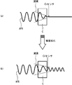
- FIGS. 2 and 3 are diagrams schematically representing the catalyst deterioration diagnosis method according to the present invention, in which the upstream air-fuel ratio AFRu of the catalyst C repeats the transition from one side to the other side of the lean side and the rich side.
- AFRu upstream air-fuel ratio
- the catalyst C is sufficiently functioning, and if the oxygen storage function and the oxygen release function are sufficiently exhibited, as shown in FIG.
- the content is kept substantially constant.
- the oxidation of hydrocarbons (HC) and carbon monoxide (CO) by the release of stored oxygen is promoted, and purification is realized by the action of the reduction promotion of nitrogen oxides (NOx) by the storage of excess oxygen. Be done.
- the oxygen storage amount OSA and the oxygen release amount OPA of the catalyst C are estimated by comparing the air-fuel ratios AFRu and AFRd detected on the upstream side and downstream side of the catalyst C. When these become smaller than a predetermined reference value, the catalyst C is diagnosed as being deteriorated.
- step S1 the fuel injection amount is feedback-controlled by the injection amount control unit 12 so that the air-fuel ratio AFRu of the exhaust gas detected by the upstream sensor 50u is maintained within an arbitrary reference AFR region.
- a range of ⁇ 5% with respect to the ideal air-fuel ratio of 14.55 is permitted as the reference AFR region.
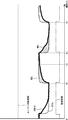
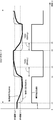
- step S2 at time t1 in FIG. 6, diagnosis injection is repeated in which increase / decrease correction of the fuel injection amount is repeated in a predetermined cycle.
- the fuel injection amount is initially corrected to be increased, whereby the pre-catalyst air-fuel ratio AFRu shifts to the rich side.
- step S3 it is determined in step S3 whether the pre-catalyst air-fuel ratio AFRu detected by the upstream sensor 50u has shifted to the lean side.
- the process proceeds to step S4, and the timer Tc starts clocking.
- step S5 the pre-catalyst air-fuel ratio AFRu detected by the upstream sensor 50u and the post-catalyst air-fuel ratio AFRd detected by the downstream sensor 50d are acquired and stored.
- step S6 the fuel injection amount represented by the engine speed NE and the fuel injection time Tout is acquired and stored.
- step S7 it is determined whether the after-catalyst air-fuel ratio AFRd detected by the downstream sensor 50d exceeds a predetermined OSA threshold. If AFRd ⁇ OSA threshold value, the process returns to step S5, and the acquisition and storage of the air-fuel ratios AFRu and AFRd and the acquisition and storage of the engine speed NE and the fuel injection amount Tout are repeated in a predetermined cycle.
- step S8 the measurement value of the measurement timer Tc is registered as the OSA time Tosa, and the measurement timer Tc is reset.
- step S9 OPA is calculated based on the OSA time Tosa, as described in detail later.
- step S10 it is determined whether or not both OSA and OPA have been calculated. If not calculated, the process proceeds to step S11, where it is determined whether the pre-catalyst air-fuel ratio AFRu detected by the upstream sensor 50u has shifted to the rich side.
- step S11 When the fuel injection amount switches to increase correction again by the diagnosis injection function, and at time t4, the pre-catalyst air-fuel ratio AFRu shifts from the rich side to the lean side and this is detected in step S11, the process proceeds to step S12 and the timer Tc proceeds. Start timing.
- step S13 the pre-catalyst air-fuel ratio AFRu detected by the upstream sensor 50u and the post-catalyst air-fuel ratio AFRd detected by the downstream sensor 50d are acquired and stored.
- step S14 the engine speed NE and the fuel injection amount Tout are acquired and stored.
- step S15 it is determined whether the after-catalyst air-fuel ratio AFRd is lower than a predetermined OPA threshold. If AFRd> OPA threshold value, the process returns to step S13, and acquisition and storage of the air-fuel ratios AFRu and AFRd, and acquisition and storage of the engine rotational speed NE and the fuel injection amount Tout are repeated in a predetermined cycle.
- step S16 the measurement value of the measurement timer Tc is registered as the OPA time Topa, and the count value of the measurement timer Tc is reset.
- step S9 OPA is calculated based on the OPA time Topa.
- the elapsed time Tosc Tosa and / or Topa
- an O 2 sensor It may be determined based on the output voltage of
- FIG. 5 is a flowchart showing the procedure of the OSC calculation process executed in step S9.
- step S31 average values AFRu_ave and AFRd_ave of AFRu and AFRd in the OSC period (OSA period or OPA period) are calculated. Be done.
- step S32 average values Ne_ave and Tout_ave of NE and Tout in the OSC period are calculated.
- step S33 the difference ⁇ AFR between the air-fuel ratio before and after the catalyst detected by each of the sensors 50u and 50d is calculated by the following equation (1).
- ⁇ AFR
- step S34 the fuel injection weight Mfuel per cycle is calculated based on the integrated value of Tout and the injection characteristic.
- step S35 the remaining oxygen amount MO 2 per cycle is calculated based on the air-fuel ratio difference ⁇ AFR and the fuel injection mass Mfuel per cycle.
- step S37 OSA and OPA are calculated based on the following equations (3) and (4).
- OSA (g) M'O 2 x Tosa (3)
- OPA (g) M'O 2 ⁇ Topa (4)
- step S10 since it is determined in step S10 that both OSA and OPA have been calculated, the process proceeds to step S17, and the deterioration state of the catalyst is determined based on OSA and OPA. In the present embodiment, it is judged that the catalyst is deteriorated if either OSA or OPA falls below a predetermined reference value, or if either one of OSA or OPA falls below the reference value.
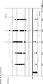
- FIG. 7 is a diagram showing the determination results of OSA and POA measured while changing the throttle opening with a constant number of engine revolutions Ne for a plurality of samples, and the selectivity is high regardless of the engine operating condition. It has been confirmed that diagnostic results can be obtained.
- the present invention is not limited to this, and only one of them is determined, and the catalyst is calculated based on only one of the two. The diagnosis may be performed.
Landscapes
- Engineering & Computer Science (AREA)
- Chemical & Material Sciences (AREA)
- Combustion & Propulsion (AREA)
- Mechanical Engineering (AREA)
- General Engineering & Computer Science (AREA)
- Chemical Kinetics & Catalysis (AREA)
- Health & Medical Sciences (AREA)
- Materials Engineering (AREA)
- Toxicology (AREA)
- Analytical Chemistry (AREA)
- General Chemical & Material Sciences (AREA)
- Oil, Petroleum & Natural Gas (AREA)
- Environmental & Geological Engineering (AREA)
- Biomedical Technology (AREA)
- Exhaust Gas After Treatment (AREA)
- Electrical Control Of Air Or Fuel Supplied To Internal-Combustion Engine (AREA)
- Combined Controls Of Internal Combustion Engines (AREA)
Abstract
Description
なお、上記の実施形態では経過時間Tosc(Tosaおよび/またはTopa)が触媒後空燃比AFRdに基づいて求められるものとして説明したが、本発明はこれのみに限定されるものではなく、O2センサの出力電圧に基づいて求めるようにしても良い。
ΔAFR=│AFRu_ave-AFRd_ave│ …(1)
M'O2=(MO2×NE)/120 …(2)
OSA(g)=M'O2×Tosa …(3)
OPA(g)=M'O2×Topa …(4)
Claims (5)
- 内燃機関の排気通路内に設けられた触媒の上流側および下流側に空燃比センサを設け、各空燃比センサの出力に基づいて触媒の劣化を判定する触媒診断装置において、
触媒の上流側で検知される空燃比がストイキ領域内に設定される基準AFRを挟んでリーン側およびリッチ側の一方から他方に振れるように燃料噴射量を制御する手段(12)と、
上流側の空燃比が前記一方から他方に振れてから下流側の空燃比センサ(50d)で検知される空燃比が所定の閾値条件を満たすまでの経過時間を計時する手段(13)と、
前記経過時間に基づいて触媒の酸素吸蔵能力(OSC)を計算する手段(17)(18)と、
前記酸素吸蔵能力に基づいて触媒の劣化を診断する手段(19)とを具備したことを特徴とする触媒診断装置。 - 前記経過時間を計時する手段は、触媒前の空燃比がリーン側に振れてから下流側の空燃比センサで検知される空燃比が所定の閾値条件を満たすまでの経過時間を計時し、
前記触媒の酸素吸蔵能力を計算する手段は、前記経過時間に基づいて触媒の還元雰囲気における酸素吸蔵量(OSA)を計算(17)することを特徴とする請求項1に記載の触媒診断装置。 - 前記経過時間を計時する手段は、触媒前の空燃比がリッチ側に振れてから下流側の空燃比センサで検知される空燃比が所定の閾値条件を満たすまでの経過時間を計時し、
前記触媒の酸素吸蔵能力を計算する手段は、前記経過時間に基づいて触媒の酸化雰囲気における酸素放出量(OPA)を計算(18)することを特徴とする請求項1または2に記載の触媒診断装置。 - 前記燃料噴射量を制御する前に、触媒前の空燃比をストイキ領域に所定の期間だけ制御する手段(12)をさらに具備したことを特徴とする請求項1ないし3のいずれかに記載の触媒診断装置。
- 前記触媒の酸素吸蔵能力を計算する手段は、
前記経過時間内に各センサが検知した空燃比の平均値の差分を算出する手段(14)と、
エンジンの1サイクル当たりの燃料重量を計算する手段(15)と、
エンジン回転数を算出する手段(16)とを具備し、
触媒の酸素吸蔵能力を、前記空燃比の平均値の差分、燃料重量、エンジン回転数および経過時間の関数として計算することを特徴とする請求項1ないし4のいずれかに記載の触媒診断装置。
Priority Applications (6)
| Application Number | Priority Date | Filing Date | Title |
|---|---|---|---|
| EP16896800.6A EP3438432A4 (en) | 2016-03-29 | 2016-03-29 | CATALYST DIAGNOSIS DEVICE |
| US16/089,216 US10774767B2 (en) | 2016-03-29 | 2016-03-29 | Catalyst diagnosis device |
| BR112018069649-8A BR112018069649B1 (pt) | 2016-03-29 | 2016-03-29 | Dispositivo de diagnóstico de catalisador |
| JP2018507894A JP6611397B2 (ja) | 2016-03-29 | 2016-03-29 | 触媒診断装置 |
| PCT/JP2016/060197 WO2017168580A1 (ja) | 2016-03-29 | 2016-03-29 | 触媒診断装置 |
| CN201680084164.4A CN108884774B (zh) | 2016-03-29 | 2016-03-29 | 催化剂诊断装置 |
Applications Claiming Priority (1)
| Application Number | Priority Date | Filing Date | Title |
|---|---|---|---|
| PCT/JP2016/060197 WO2017168580A1 (ja) | 2016-03-29 | 2016-03-29 | 触媒診断装置 |
Publications (1)
| Publication Number | Publication Date |
|---|---|
| WO2017168580A1 true WO2017168580A1 (ja) | 2017-10-05 |
Family
ID=59962706
Family Applications (1)
| Application Number | Title | Priority Date | Filing Date |
|---|---|---|---|
| PCT/JP2016/060197 WO2017168580A1 (ja) | 2016-03-29 | 2016-03-29 | 触媒診断装置 |
Country Status (6)
| Country | Link |
|---|---|
| US (1) | US10774767B2 (ja) |
| EP (1) | EP3438432A4 (ja) |
| JP (1) | JP6611397B2 (ja) |
| CN (1) | CN108884774B (ja) |
| BR (1) | BR112018069649B1 (ja) |
| WO (1) | WO2017168580A1 (ja) |
Cited By (2)
| Publication number | Priority date | Publication date | Assignee | Title |
|---|---|---|---|---|
| WO2021176671A1 (ja) * | 2020-03-05 | 2021-09-10 | 本田技研工業株式会社 | 触媒劣化診断装置 |
| WO2022091523A1 (ja) * | 2020-10-29 | 2022-05-05 | 日立Astemo株式会社 | 内燃機関の制御装置及び触媒劣化診断方法 |
Families Citing this family (4)
| Publication number | Priority date | Publication date | Assignee | Title |
|---|---|---|---|---|
| FR3101667A1 (fr) * | 2019-10-02 | 2021-04-09 | Psa Automobiles Sa | Procédé de commande d’une boite de vitesse pour une mesure de diagnostic dans une plage de régime moteur prédéterminée |
| JP7151696B2 (ja) * | 2019-12-25 | 2022-10-12 | トヨタ自動車株式会社 | 触媒劣化検出装置 |
| FR3119643B1 (fr) * | 2021-02-08 | 2022-12-23 | Psa Automobiles Sa | Procede de regulation du fonctionnement d'un catalyseur de gaz d'echappement produits par le moteur thermique d'un vehicule automobile |
| US11624333B2 (en) | 2021-04-20 | 2023-04-11 | Kohler Co. | Exhaust safety system for an engine |
Citations (6)
| Publication number | Priority date | Publication date | Assignee | Title |
|---|---|---|---|---|
| JPH0230915A (ja) * | 1988-07-20 | 1990-02-01 | Toyota Motor Corp | 内燃機関の触媒劣化判別装置 |
| JPH0233408A (ja) * | 1988-07-21 | 1990-02-02 | Toyota Motor Corp | 内燃機関の触媒劣化判別装置 |
| JPH02207159A (ja) * | 1989-02-03 | 1990-08-16 | Toyota Motor Corp | 内燃機関の触媒劣化判別装置 |
| JP2005127259A (ja) * | 2003-10-24 | 2005-05-19 | Hitachi Ltd | エンジンの制御装置 |
| JP2005163618A (ja) * | 2003-12-02 | 2005-06-23 | Hitachi Ltd | エンジンの制御装置 |
| JP2008291751A (ja) * | 2007-05-24 | 2008-12-04 | Toyota Motor Corp | 内燃機関の触媒劣化検出装置 |
Family Cites Families (20)
| Publication number | Priority date | Publication date | Assignee | Title |
|---|---|---|---|---|
| US5088281A (en) | 1988-07-20 | 1992-02-18 | Toyota Jidosha Kabushiki Kaisha | Method and apparatus for determining deterioration of three-way catalysts in double air-fuel ratio sensor system |
| JP2003254049A (ja) * | 2002-03-06 | 2003-09-10 | Denso Corp | 排出ガスセンサの異常診断装置 |
| DE10218015A1 (de) * | 2002-04-23 | 2003-11-06 | Bosch Gmbh Robert | Verfahren und Vorrichtung zur Diagnose eines Katalysators |
| DE10257059B4 (de) * | 2002-12-06 | 2013-05-23 | Volkswagen Ag | Verfahren und Vorrichtung zur Diagnose von Katalysatoreinheiten |
| JP3873904B2 (ja) * | 2003-02-26 | 2007-01-31 | 日産自動車株式会社 | 内燃機関の排気浄化装置 |
| JP4042690B2 (ja) * | 2003-12-16 | 2008-02-06 | トヨタ自動車株式会社 | 内燃機関の触媒劣化診断装置 |
| JP2005220901A (ja) * | 2004-01-06 | 2005-08-18 | Toyota Motor Corp | 内燃機関の触媒劣化状態評価装置 |
| JP2006125279A (ja) * | 2004-10-28 | 2006-05-18 | Mitsubishi Electric Corp | 内燃機関制御装置 |
| JP4384129B2 (ja) * | 2006-03-24 | 2009-12-16 | 本田技研工業株式会社 | 触媒劣化検出装置 |
| JP4221026B2 (ja) * | 2006-12-25 | 2009-02-12 | 三菱電機株式会社 | 内燃機関の空燃比制御装置 |
| JP4637213B2 (ja) * | 2008-06-20 | 2011-02-23 | 本田技研工業株式会社 | 触媒の劣化判定装置 |
| JP2009299557A (ja) * | 2008-06-12 | 2009-12-24 | Honda Motor Co Ltd | 触媒の劣化判定装置 |
| JP2010084750A (ja) * | 2008-09-04 | 2010-04-15 | Denso Corp | 排気浄化用触媒の劣化診断装置 |
| EP2538047B1 (en) * | 2010-02-15 | 2017-12-20 | Toyota Jidosha Kabushiki Kaisha | Catalyst deterioration diagnosis device for internal combustion engine |
| US8745971B2 (en) * | 2010-03-11 | 2014-06-10 | Cummins Inc. | System, method, and apparatus for controlling an aftertreatment system having a particulate filter and a rich NOx conversion device |
| JP2012117406A (ja) * | 2010-11-30 | 2012-06-21 | Daihatsu Motor Co Ltd | 内燃機関の触媒異常判定方法 |
| EP2857663A4 (en) | 2012-05-28 | 2016-01-13 | Toyota Motor Co Ltd | CATALYST DEGRADATION DETERMINATION SYSTEM |
| DE102012025002A1 (de) * | 2012-12-20 | 2014-06-26 | Volkswagen Aktiengesellschaft | Verfahren zur Diagnose eines Abgaskatalysators, Diagnoseeinrichtung sowie Kraftfahrzeug mit einer solchen |
| JP6110270B2 (ja) * | 2013-10-02 | 2017-04-05 | トヨタ自動車株式会社 | 内燃機関の異常診断装置 |
| JP6160568B2 (ja) * | 2014-06-20 | 2017-07-12 | トヨタ自動車株式会社 | 排気浄化装置の劣化診断装置 |
-
2016
- 2016-03-29 US US16/089,216 patent/US10774767B2/en active Active
- 2016-03-29 CN CN201680084164.4A patent/CN108884774B/zh active Active
- 2016-03-29 WO PCT/JP2016/060197 patent/WO2017168580A1/ja active Application Filing
- 2016-03-29 EP EP16896800.6A patent/EP3438432A4/en active Pending
- 2016-03-29 BR BR112018069649-8A patent/BR112018069649B1/pt active IP Right Grant
- 2016-03-29 JP JP2018507894A patent/JP6611397B2/ja active Active
Patent Citations (6)
| Publication number | Priority date | Publication date | Assignee | Title |
|---|---|---|---|---|
| JPH0230915A (ja) * | 1988-07-20 | 1990-02-01 | Toyota Motor Corp | 内燃機関の触媒劣化判別装置 |
| JPH0233408A (ja) * | 1988-07-21 | 1990-02-02 | Toyota Motor Corp | 内燃機関の触媒劣化判別装置 |
| JPH02207159A (ja) * | 1989-02-03 | 1990-08-16 | Toyota Motor Corp | 内燃機関の触媒劣化判別装置 |
| JP2005127259A (ja) * | 2003-10-24 | 2005-05-19 | Hitachi Ltd | エンジンの制御装置 |
| JP2005163618A (ja) * | 2003-12-02 | 2005-06-23 | Hitachi Ltd | エンジンの制御装置 |
| JP2008291751A (ja) * | 2007-05-24 | 2008-12-04 | Toyota Motor Corp | 内燃機関の触媒劣化検出装置 |
Non-Patent Citations (1)
| Title |
|---|
| See also references of EP3438432A4 * |
Cited By (4)
| Publication number | Priority date | Publication date | Assignee | Title |
|---|---|---|---|---|
| WO2021176671A1 (ja) * | 2020-03-05 | 2021-09-10 | 本田技研工業株式会社 | 触媒劣化診断装置 |
| JP7372440B2 (ja) | 2020-03-05 | 2023-10-31 | 本田技研工業株式会社 | 触媒劣化診断装置 |
| WO2022091523A1 (ja) * | 2020-10-29 | 2022-05-05 | 日立Astemo株式会社 | 内燃機関の制御装置及び触媒劣化診断方法 |
| JP7454068B2 (ja) | 2020-10-29 | 2024-03-21 | 日立Astemo株式会社 | 内燃機関の制御装置及び触媒劣化診断方法 |
Also Published As
| Publication number | Publication date |
|---|---|
| JP6611397B2 (ja) | 2019-11-27 |
| CN108884774A (zh) | 2018-11-23 |
| BR112018069649B1 (pt) | 2023-02-14 |
| BR112018069649A2 (pt) | 2019-01-29 |
| US20200032730A1 (en) | 2020-01-30 |
| EP3438432A4 (en) | 2019-04-17 |
| CN108884774B (zh) | 2021-07-23 |
| US10774767B2 (en) | 2020-09-15 |
| EP3438432A1 (en) | 2019-02-06 |
| JPWO2017168580A1 (ja) | 2019-02-14 |
Similar Documents
| Publication | Publication Date | Title |
|---|---|---|
| WO2017168580A1 (ja) | 触媒診断装置 | |
| JP3674017B2 (ja) | 排出ガス浄化用触媒劣化検出装置 | |
| US8146346B2 (en) | NOx trapping catalytic converter diagnostic apparatus | |
| JP4798508B2 (ja) | 触媒の劣化診断装置 | |
| JP5024676B2 (ja) | 触媒劣化抑制装置 | |
| EP2052137B1 (en) | Catalyst monitoring system and method | |
| JP3887903B2 (ja) | 内燃機関の空燃比制御装置 | |
| JP3997599B2 (ja) | 内燃機関の空燃比制御装置 | |
| JP2900890B2 (ja) | 内燃機関の触媒劣化判別装置 | |
| WO2007145141A1 (ja) | 触媒劣化検出装置 | |
| JP4637213B2 (ja) | 触媒の劣化判定装置 | |
| JP2020045885A (ja) | 触媒劣化診断システムおよび触媒劣化診断方法 | |
| JP4737482B2 (ja) | 内燃機関の触媒劣化検出装置 | |
| JP2009036172A (ja) | 内燃機関の触媒劣化診断装置 | |
| JP4366976B2 (ja) | 排気ガスセンサの異常検出装置 | |
| JP2010255490A (ja) | 触媒異常診断装置 | |
| JP3520730B2 (ja) | エンジンの触媒劣化診断装置 | |
| JP2004301103A (ja) | 排気ガス浄化触媒の劣化診断装置 | |
| JP4779814B2 (ja) | 内燃機関の触媒代表温度取得装置 | |
| JP4411755B2 (ja) | 排気浄化触媒の劣化状態診断装置 | |
| JP2010168923A (ja) | 触媒劣化診断装置 | |
| JP2004232576A (ja) | 内燃機関の排気浄化装置 | |
| WO2023238361A1 (ja) | 内燃機関の制御方法および制御装置 | |
| JP2011231626A (ja) | 触媒異常診断装置 | |
| JP3624689B2 (ja) | 内燃機関の排気ガス浄化装置 |
Legal Events
| Date | Code | Title | Description |
|---|---|---|---|
| WWE | Wipo information: entry into national phase |
Ref document number: 2018507894 Country of ref document: JP |
|
| NENP | Non-entry into the national phase |
Ref country code: DE |
|
| REG | Reference to national code |
Ref country code: BR Ref legal event code: B01A Ref document number: 112018069649 Country of ref document: BR |
|
| WWE | Wipo information: entry into national phase |
Ref document number: 2016896800 Country of ref document: EP |
|
| ENP | Entry into the national phase |
Ref document number: 2016896800 Country of ref document: EP Effective date: 20181029 |
|
| 121 | Ep: the epo has been informed by wipo that ep was designated in this application |
Ref document number: 16896800 Country of ref document: EP Kind code of ref document: A1 |
|
| ENP | Entry into the national phase |
Ref document number: 112018069649 Country of ref document: BR Kind code of ref document: A2 Effective date: 20180926 |