WO2017168522A1 - 電力変換装置 - Google Patents
電力変換装置 Download PDFInfo
- Publication number
- WO2017168522A1 WO2017168522A1 PCT/JP2016/059931 JP2016059931W WO2017168522A1 WO 2017168522 A1 WO2017168522 A1 WO 2017168522A1 JP 2016059931 W JP2016059931 W JP 2016059931W WO 2017168522 A1 WO2017168522 A1 WO 2017168522A1
- Authority
- WO
- WIPO (PCT)
- Prior art keywords
- voltage
- phase
- inverter
- offset
- offset voltage
- Prior art date
Links
Images


Classifications
-
- H—ELECTRICITY
- H02—GENERATION; CONVERSION OR DISTRIBUTION OF ELECTRIC POWER
- H02M—APPARATUS FOR CONVERSION BETWEEN AC AND AC, BETWEEN AC AND DC, OR BETWEEN DC AND DC, AND FOR USE WITH MAINS OR SIMILAR POWER SUPPLY SYSTEMS; CONVERSION OF DC OR AC INPUT POWER INTO SURGE OUTPUT POWER; CONTROL OR REGULATION THEREOF
- H02M7/00—Conversion of ac power input into dc power output; Conversion of dc power input into ac power output
- H02M7/42—Conversion of dc power input into ac power output without possibility of reversal
- H02M7/44—Conversion of dc power input into ac power output without possibility of reversal by static converters
- H02M7/48—Conversion of dc power input into ac power output without possibility of reversal by static converters using discharge tubes with control electrode or semiconductor devices with control electrode
- H02M7/53—Conversion of dc power input into ac power output without possibility of reversal by static converters using discharge tubes with control electrode or semiconductor devices with control electrode using devices of a triode or transistor type requiring continuous application of a control signal
- H02M7/537—Conversion of dc power input into ac power output without possibility of reversal by static converters using discharge tubes with control electrode or semiconductor devices with control electrode using devices of a triode or transistor type requiring continuous application of a control signal using semiconductor devices only, e.g. single switched pulse inverters
- H02M7/539—Conversion of dc power input into ac power output without possibility of reversal by static converters using discharge tubes with control electrode or semiconductor devices with control electrode using devices of a triode or transistor type requiring continuous application of a control signal using semiconductor devices only, e.g. single switched pulse inverters with automatic control of output wave form or frequency
- H02M7/5395—Conversion of dc power input into ac power output without possibility of reversal by static converters using discharge tubes with control electrode or semiconductor devices with control electrode using devices of a triode or transistor type requiring continuous application of a control signal using semiconductor devices only, e.g. single switched pulse inverters with automatic control of output wave form or frequency by pulse-width modulation
-
- G—PHYSICS
- G01—MEASURING; TESTING
- G01R—MEASURING ELECTRIC VARIABLES; MEASURING MAGNETIC VARIABLES
- G01R31/00—Arrangements for testing electric properties; Arrangements for locating electric faults; Arrangements for electrical testing characterised by what is being tested not provided for elsewhere
- G01R31/40—Testing power supplies
- G01R31/42—AC power supplies
-
- H—ELECTRICITY
- H02—GENERATION; CONVERSION OR DISTRIBUTION OF ELECTRIC POWER
- H02H—EMERGENCY PROTECTIVE CIRCUIT ARRANGEMENTS
- H02H7/00—Emergency protective circuit arrangements specially adapted for specific types of electric machines or apparatus or for sectionalised protection of cable or line systems, and effecting automatic switching in the event of an undesired change from normal working conditions
- H02H7/10—Emergency protective circuit arrangements specially adapted for specific types of electric machines or apparatus or for sectionalised protection of cable or line systems, and effecting automatic switching in the event of an undesired change from normal working conditions for converters; for rectifiers
- H02H7/12—Emergency protective circuit arrangements specially adapted for specific types of electric machines or apparatus or for sectionalised protection of cable or line systems, and effecting automatic switching in the event of an undesired change from normal working conditions for converters; for rectifiers for static converters or rectifiers
- H02H7/122—Emergency protective circuit arrangements specially adapted for specific types of electric machines or apparatus or for sectionalised protection of cable or line systems, and effecting automatic switching in the event of an undesired change from normal working conditions for converters; for rectifiers for static converters or rectifiers for inverters, i.e. dc/ac converters
- H02H7/1225—Emergency protective circuit arrangements specially adapted for specific types of electric machines or apparatus or for sectionalised protection of cable or line systems, and effecting automatic switching in the event of an undesired change from normal working conditions for converters; for rectifiers for static converters or rectifiers for inverters, i.e. dc/ac converters responsive to internal faults, e.g. shoot-through
-
- H—ELECTRICITY
- H02—GENERATION; CONVERSION OR DISTRIBUTION OF ELECTRIC POWER
- H02M—APPARATUS FOR CONVERSION BETWEEN AC AND AC, BETWEEN AC AND DC, OR BETWEEN DC AND DC, AND FOR USE WITH MAINS OR SIMILAR POWER SUPPLY SYSTEMS; CONVERSION OF DC OR AC INPUT POWER INTO SURGE OUTPUT POWER; CONTROL OR REGULATION THEREOF
- H02M1/00—Details of apparatus for conversion
- H02M1/08—Circuits specially adapted for the generation of control voltages for semiconductor devices incorporated in static converters
-
- H—ELECTRICITY
- H02—GENERATION; CONVERSION OR DISTRIBUTION OF ELECTRIC POWER
- H02M—APPARATUS FOR CONVERSION BETWEEN AC AND AC, BETWEEN AC AND DC, OR BETWEEN DC AND DC, AND FOR USE WITH MAINS OR SIMILAR POWER SUPPLY SYSTEMS; CONVERSION OF DC OR AC INPUT POWER INTO SURGE OUTPUT POWER; CONTROL OR REGULATION THEREOF
- H02M1/00—Details of apparatus for conversion
- H02M1/38—Means for preventing simultaneous conduction of switches
-
- H—ELECTRICITY
- H02—GENERATION; CONVERSION OR DISTRIBUTION OF ELECTRIC POWER
- H02M—APPARATUS FOR CONVERSION BETWEEN AC AND AC, BETWEEN AC AND DC, OR BETWEEN DC AND DC, AND FOR USE WITH MAINS OR SIMILAR POWER SUPPLY SYSTEMS; CONVERSION OF DC OR AC INPUT POWER INTO SURGE OUTPUT POWER; CONTROL OR REGULATION THEREOF
- H02M7/00—Conversion of ac power input into dc power output; Conversion of dc power input into ac power output
- H02M7/42—Conversion of dc power input into ac power output without possibility of reversal
- H02M7/44—Conversion of dc power input into ac power output without possibility of reversal by static converters
- H02M7/48—Conversion of dc power input into ac power output without possibility of reversal by static converters using discharge tubes with control electrode or semiconductor devices with control electrode
- H02M7/53—Conversion of dc power input into ac power output without possibility of reversal by static converters using discharge tubes with control electrode or semiconductor devices with control electrode using devices of a triode or transistor type requiring continuous application of a control signal
- H02M7/537—Conversion of dc power input into ac power output without possibility of reversal by static converters using discharge tubes with control electrode or semiconductor devices with control electrode using devices of a triode or transistor type requiring continuous application of a control signal using semiconductor devices only, e.g. single switched pulse inverters
- H02M7/5387—Conversion of dc power input into ac power output without possibility of reversal by static converters using discharge tubes with control electrode or semiconductor devices with control electrode using devices of a triode or transistor type requiring continuous application of a control signal using semiconductor devices only, e.g. single switched pulse inverters in a bridge configuration
- H02M7/53871—Conversion of dc power input into ac power output without possibility of reversal by static converters using discharge tubes with control electrode or semiconductor devices with control electrode using devices of a triode or transistor type requiring continuous application of a control signal using semiconductor devices only, e.g. single switched pulse inverters in a bridge configuration with automatic control of output voltage or current
- H02M7/53875—Conversion of dc power input into ac power output without possibility of reversal by static converters using discharge tubes with control electrode or semiconductor devices with control electrode using devices of a triode or transistor type requiring continuous application of a control signal using semiconductor devices only, e.g. single switched pulse inverters in a bridge configuration with automatic control of output voltage or current with analogue control of three-phase output
-
- G—PHYSICS
- G01—MEASURING; TESTING
- G01R—MEASURING ELECTRIC VARIABLES; MEASURING MAGNETIC VARIABLES
- G01R31/00—Arrangements for testing electric properties; Arrangements for locating electric faults; Arrangements for electrical testing characterised by what is being tested not provided for elsewhere
- G01R31/50—Testing of electric apparatus, lines, cables or components for short-circuits, continuity, leakage current or incorrect line connections
- G01R31/52—Testing for short-circuits, leakage current or ground faults
-
- H—ELECTRICITY
- H02—GENERATION; CONVERSION OR DISTRIBUTION OF ELECTRIC POWER
- H02M—APPARATUS FOR CONVERSION BETWEEN AC AND AC, BETWEEN AC AND DC, OR BETWEEN DC AND DC, AND FOR USE WITH MAINS OR SIMILAR POWER SUPPLY SYSTEMS; CONVERSION OF DC OR AC INPUT POWER INTO SURGE OUTPUT POWER; CONTROL OR REGULATION THEREOF
- H02M1/00—Details of apparatus for conversion
- H02M1/0003—Details of control, feedback or regulation circuits
- H02M1/0009—Devices or circuits for detecting current in a converter
-
- H—ELECTRICITY
- H02—GENERATION; CONVERSION OR DISTRIBUTION OF ELECTRIC POWER
- H02M—APPARATUS FOR CONVERSION BETWEEN AC AND AC, BETWEEN AC AND DC, OR BETWEEN DC AND DC, AND FOR USE WITH MAINS OR SIMILAR POWER SUPPLY SYSTEMS; CONVERSION OF DC OR AC INPUT POWER INTO SURGE OUTPUT POWER; CONTROL OR REGULATION THEREOF
- H02M1/00—Details of apparatus for conversion
- H02M1/0003—Details of control, feedback or regulation circuits
- H02M1/0025—Arrangements for modifying reference values, feedback values or error values in the control loop of a converter
-
- H—ELECTRICITY
- H02—GENERATION; CONVERSION OR DISTRIBUTION OF ELECTRIC POWER
- H02M—APPARATUS FOR CONVERSION BETWEEN AC AND AC, BETWEEN AC AND DC, OR BETWEEN DC AND DC, AND FOR USE WITH MAINS OR SIMILAR POWER SUPPLY SYSTEMS; CONVERSION OF DC OR AC INPUT POWER INTO SURGE OUTPUT POWER; CONTROL OR REGULATION THEREOF
- H02M1/00—Details of apparatus for conversion
- H02M1/44—Circuits or arrangements for compensating for electromagnetic interference in converters or inverters
-
- H—ELECTRICITY
- H02—GENERATION; CONVERSION OR DISTRIBUTION OF ELECTRIC POWER
- H02P—CONTROL OR REGULATION OF ELECTRIC MOTORS, ELECTRIC GENERATORS OR DYNAMO-ELECTRIC CONVERTERS; CONTROLLING TRANSFORMERS, REACTORS OR CHOKE COILS
- H02P27/00—Arrangements or methods for the control of AC motors characterised by the kind of supply voltage
- H02P27/04—Arrangements or methods for the control of AC motors characterised by the kind of supply voltage using variable-frequency supply voltage, e.g. inverter or converter supply voltage
- H02P27/06—Arrangements or methods for the control of AC motors characterised by the kind of supply voltage using variable-frequency supply voltage, e.g. inverter or converter supply voltage using dc to ac converters or inverters
- H02P27/08—Arrangements or methods for the control of AC motors characterised by the kind of supply voltage using variable-frequency supply voltage, e.g. inverter or converter supply voltage using dc to ac converters or inverters with pulse width modulation
Abstract
Description
そのため、出力電圧の歪み率を低減するとともに、騒音、振動を低減することができる。
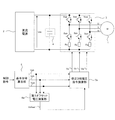
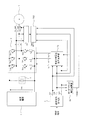
図1は、この発明の実施の形態1に係る電力変換装置を示す全体構成図である。図1において、交流回転機1は、3相巻線U、V、Wを有する交流回転機であり、例えば、永久磁石同期回転機、巻線界磁同期回転機、誘導回転機、シンクロナスリラクタンスモータ等である。

これにより、3相変調の利用範囲を増大することができるとともに、変調方式を切り替える際に、不連続な電圧変化が生じることがない。そのため、出力電圧の歪み率を低減するとともに、騒音、振動を低減することができる。
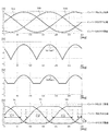
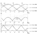
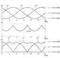
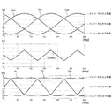
上記実施の形態1において、3相電圧指令の振幅値が4.33Vである図4に比べ、3相電圧指令の振幅値を5.48Vに増大させた場合における3相電圧指令Vub、Vvb、Vwb、第1オフセット電圧Voffset1’、第1オフセット電圧Voffset1および修正3相電圧指令Vu、Vv、Vwを図5に示す。
以下、実施の形態3について述べるが、実施の形態1、2と重複する箇所については説明を省略する。実施の形態3が実施の形態2と異なるのは、第2オフセット電圧演算部6bである。
以下、実施の形態4について述べるが、実施の形態1~3と重複する箇所については説明を省略する。実施の形態4が実施の形態2と異なるのは、第2オフセット電圧演算部6bである。
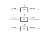
以下、実施の形態5について述べるが、実施の形態1と重複する箇所については説明を省略する。図14は、この発明の実施の形態5に係る電力変換装置を示す全体構成図である。実施の形態5が実施の形態1と異なるのは、出力電圧検出回路501、502、503およびインバータ故障検出部504である。
以下、実施の形態6について述べるが、実施の形態1と重複する箇所については説明を省略する。図17は、この発明の実施の形態6に係る電力変換装置を示す全体構成図である。実施の形態6が実施の形態1と異なるのは、出力電圧検出回路601、602、603およびインバータ故障検出部604である。
以下、実施の形態7について述べるが、実施の形態1と重複する箇所については説明を省略する。図20は、この発明の実施の形態7に係る電力変換装置を示す全体構成図である。実施の形態7が実施の形態1と異なるのは、出力電圧検出回路701およびインバータ故障検出部702である。
Claims (18)
- それぞれ正弦波となる3相電圧指令に基づいて直流電圧を3相電圧に変換して出力する電力変換装置であって、
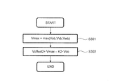
前記3相電圧指令を大きい順に最大相、中間相、最小相としたとき、前記直流電圧に第1定数を乗算した第1直流電圧を、前記最大相から減算して第1オフセット電圧を演算するとともに、前記第1オフセット電圧の符号が負の場合に、前記第1オフセット電圧を0に設定する第1オフセット電圧演算部と、
前記3相電圧指令の各相から前記第1オフセット電圧を減算して、修正3相電圧指令を出力する修正3相電圧指令演算部と、
前記修正3相電圧指令に基づいて、前記3相電圧を出力するインバータと、
を備えた電力変換装置。 - 前記インバータは、下側アームスイッチング素子に直列接続された電流検出用抵抗素子の電圧降下によって、インバータの各相を流れる電流を検出する電流検出部を備え、
前記第1オフセット電圧演算部は、前記下側アームスイッチング素子の通電時間が前記電流検出用抵抗素子で前記電流の検出が可能な下限値となるように前記第1定数を設定する
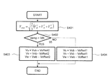
請求項1に記載の電力変換装置。 - 前記電力変換装置は、前記最大相、前記最小相、前記直流電圧の少なくとも2つに基づいて第2オフセット電圧を演算する第2オフセット電圧演算部を備え、
前記修正3相電圧指令部は、前記3相電圧指令の振幅があらかじめ設定された閾値よりも大きい場合に、前記3相電圧指令から前記第2オフセット電圧を減算することで、前記修正3相電圧指令を出力する
請求項1または請求項2に記載の電力変換装置。 - 前記第2オフセット電圧演算部は、前記最大相から前記直流電圧に第2定数を乗算した第2直流電圧を減算することで、前記第2オフセット電圧を演算するものであって、前記第2定数は、前記インバータから出力される電圧のうち、最も大きい相の電圧があらかじめ設定された上限値となるように設定される
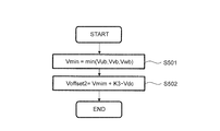
請求項3に記載の電力変換装置。 - 前記第2オフセット電圧演算部は、前記最小相と前記直流電圧に第3定数を乗算した第3直流電圧とを加算することで、前記第2オフセット電圧を演算するものであって、前記第3定数は、前記インバータから出力される電圧のうち、最も小さい相の電圧があらかじめ設定された下限値となるように設定される
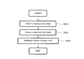
請求項3に記載の電力変換装置。 - 前記第2オフセット電圧演算部は、前記最大相と前記最小相との平均値を第2オフセット電圧とする
請求項3に記載の電力変換装置。 - 前記電力変換装置は、前記インバータから出力される前記3相電圧を検出する出力電圧検出回路を各相に備え、前記3相電圧に基づいて前記インバータの故障を判定する
請求項1から請求項6までの何れか1項に記載の電力変換装置。 - 前記電力変換装置は、前記出力電圧検出回路により検出された前記3相電圧から、その搬送波成分を除去した前記3相電圧に基づいて、前記インバータの故障を判定する
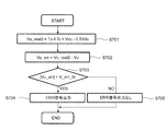
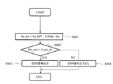
請求項7に記載の電力変換装置。 - 前記電力変換装置は、前記出力電圧検出回路により検出された前記3相電圧から、その搬送波成分を除去した前記3相電圧の各相の加算値があらかじめ設定された閾値から逸脱した場合に、前記インバータの故障を判定する
請求項7に記載の電力変換装置。 - それぞれ正弦波となる3相電圧指令に基づいて直流電圧を3相電圧に変換して出力する電力変換装置であって、
前記3相電圧指令を大きい順に最大相、中間相、最小相としたとき、前記最小相と前記直流電圧に第4定数を乗算した第4直流電圧とを加算することで、第3オフセット電圧を演算し、前記第3オフセット電圧の符号が正の場合に前記第3オフセット電圧を0に修正する第3オフセット電圧演算部と、
前記3相電圧指令の各相から前記第3オフセット電圧で減算して、修正3相電圧指令を出力する修正3相電圧指令演算部と、
前記修正3相電圧指令に基づいて、前記3相電圧を出力するインバータと、
を備えた電力変換装置。 - 前記インバータは、上側アームスイッチング素子に直列接続された電流検出用抵抗素子の電圧降下によって、インバータの各相を流れる電流を検出する電流検出部を備え、
前記第3オフセット電圧演算部は、前記上側アームスイッチング素子の通電時間が前記電流検出用抵抗素子で前記電流の検出が可能な下限値となるように前記第4定数を設定する
請求項10に記載の電力変換装置。 - 前記電力変換装置は、前記最大相、前記最小相、前記直流電圧の少なくとも2つに基づいて第4オフセット電圧を演算する第4オフセット電圧演算部を備え、
前記修正3相電圧指令部は、前記3相電圧指令の振幅があらかじめ設定された閾値よりも大きい場合に、前記3相電圧指令から前記第4オフセット電圧を減算することで、前記修正3相電圧指令を出力する
請求項10または請求項11に記載の電力変換装置。 - 前記第4オフセット電圧演算部は、前記最大相から前記直流電圧に第5定数を乗算した第5直流電圧を減算することで、前記第4オフセット電圧を演算するものであって、前記第5定数は、前記インバータから出力される電圧のうち、最も大きい相の電圧があらかじめ設定された上限値となるように設定される
請求項12に記載の電力変換装置。 - 前記第4オフセット電圧演算部は、前記最小相と前記直流電圧に第6定数を乗算した第6直流電圧とを加算することで、前記第4オフセット電圧を演算するものであって、前記第6定数は、前記インバータから出力される電圧のうち、最も小さい相の電圧があらかじめ設定された下限値となるように設定される
請求項12に記載の電力変換装置。 - 前記第4オフセット電圧演算部は、前記最大相と前記最小相との平均値を第2オフセット電圧とする
請求項12に記載の電力変換装置。 - 前記電力変換装置は、前記インバータから出力される前記3相電圧を検出する出力電圧検出回路を各相に備え、前記3相電圧に基づいて前記インバータの故障を判定する
請求項10から請求項15までの何れか1項に記載の電力変換装置。 - 前記電力変換装置は、前記出力電圧検出回路により検出された前記3相電圧から、その搬送波成分を除去した前記3相電圧に基づいて、前記インバータの故障を判定する
請求項16に記載の電力変換装置。 - 前記電力変換装置は、前記出力電圧検出回路により検出された前記3相電圧から、その搬送波成分を除去した前記3相電圧の各相の加算値があらかじめ設定された閾値から逸脱した場合に、前記インバータの故障を判定する
請求項16に記載の電力変換装置。
Priority Applications (6)
| Application Number | Priority Date | Filing Date | Title |
|---|---|---|---|
| PCT/JP2016/059931 WO2017168522A1 (ja) | 2016-03-28 | 2016-03-28 | 電力変換装置 |
| EP16896742.0A EP3439163B1 (en) | 2016-03-28 | 2016-03-28 | Power converter |
| JP2018507845A JP6525364B2 (ja) | 2016-03-28 | 2016-03-28 | 電力変換装置 |
| EP22183544.0A EP4092901A1 (en) | 2016-03-28 | 2016-03-28 | Power converter |
| CN201680083842.5A CN109121454B (zh) | 2016-03-28 | 2016-03-28 | 功率转换装置 |
| US16/079,176 US10411615B2 (en) | 2016-03-28 | 2016-03-28 | Power converter |
Applications Claiming Priority (1)
| Application Number | Priority Date | Filing Date | Title |
|---|---|---|---|
| PCT/JP2016/059931 WO2017168522A1 (ja) | 2016-03-28 | 2016-03-28 | 電力変換装置 |
Publications (1)
| Publication Number | Publication Date |
|---|---|
| WO2017168522A1 true WO2017168522A1 (ja) | 2017-10-05 |
Family
ID=59963678
Family Applications (1)
| Application Number | Title | Priority Date | Filing Date |
|---|---|---|---|
| PCT/JP2016/059931 WO2017168522A1 (ja) | 2016-03-28 | 2016-03-28 | 電力変換装置 |
Country Status (5)
| Country | Link |
|---|---|
| US (1) | US10411615B2 (ja) |
| EP (2) | EP4092901A1 (ja) |
| JP (1) | JP6525364B2 (ja) |
| CN (1) | CN109121454B (ja) |
| WO (1) | WO2017168522A1 (ja) |
Cited By (3)
| Publication number | Priority date | Publication date | Assignee | Title |
|---|---|---|---|---|
| WO2022181084A1 (ja) * | 2021-02-25 | 2022-09-01 | 日本電産株式会社 | インバータ回路およびモータモジュール |
| WO2022208911A1 (ja) * | 2021-03-30 | 2022-10-06 | 日本電産株式会社 | 電力変換装置およびモータモジュール |
| JP7471414B2 (ja) | 2020-06-16 | 2024-04-19 | 三菱電機株式会社 | 電力変換装置、及び電動パワーステアリング装置 |
Families Citing this family (4)
| Publication number | Priority date | Publication date | Assignee | Title |
|---|---|---|---|---|
| DE102020111901B3 (de) * | 2020-05-03 | 2021-04-22 | Iav Gmbh Ingenieurgesellschaft Auto Und Verkehr | Verfahren und Vorrichtung zur Bestimmung des Zwischenkreisstromes eines Stromrichters |
| EP4030611B1 (en) * | 2020-11-17 | 2022-12-21 | Jiangsu Contemporary Amperex Technology Limited | Control method and device for grid-connected inverter |
| WO2022130480A1 (ja) * | 2020-12-15 | 2022-06-23 | 三菱電機株式会社 | 電力変換装置 |
| CN116054620A (zh) * | 2021-10-28 | 2023-05-02 | 台达电子工业股份有限公司 | 功率转换器的控制方法与功率转换器 |
Citations (2)
| Publication number | Priority date | Publication date | Assignee | Title |
|---|---|---|---|---|
| JP2005253229A (ja) * | 2004-03-05 | 2005-09-15 | Mitsubishi Electric Corp | 相電圧指令値補正方法およびこの相電圧指令値補正方法を使用したモータ制御装置 |
| JP2009189203A (ja) * | 2008-02-08 | 2009-08-20 | Denso Corp | Eps用モータ駆動装置 |
Family Cites Families (10)
| Publication number | Priority date | Publication date | Assignee | Title |
|---|---|---|---|---|
| JP2577738B2 (ja) | 1987-05-20 | 1997-02-05 | 三菱電機株式会社 | Pwmインバ−タ装置 |
| JP2006081327A (ja) * | 2004-09-10 | 2006-03-23 | Mitsubishi Electric Corp | インバータの故障検出装置 |
| JP4082438B2 (ja) * | 2006-08-30 | 2008-04-30 | ダイキン工業株式会社 | 電流制御形電力変換装置 |
| JP5122505B2 (ja) * | 2009-03-09 | 2013-01-16 | 株式会社日立産機システム | 電力変換装置及びその制御方法 |
| WO2010119929A1 (ja) * | 2009-04-16 | 2010-10-21 | 株式会社明電舎 | 電力変換装置の制御方法 |
| JP5354369B2 (ja) | 2009-09-09 | 2013-11-27 | 株式会社デンソー | 電力変換装置 |
| JP5161985B2 (ja) * | 2011-02-16 | 2013-03-13 | 三菱電機株式会社 | 電力変換装置および電動パワーステアリングの制御装置 |
| JP5831444B2 (ja) * | 2012-12-26 | 2015-12-09 | 株式会社デンソー | 回転機の制御装置 |
| US9553540B2 (en) * | 2015-01-21 | 2017-01-24 | Ford Global Technologies, Llc | Power converter with pre-compensation for dead-time insertion |
| JP2019013071A (ja) * | 2017-06-29 | 2019-01-24 | ルネサスエレクトロニクス株式会社 | 演算装置及び処理装置 |
-
2016
- 2016-03-28 EP EP22183544.0A patent/EP4092901A1/en active Pending
- 2016-03-28 EP EP16896742.0A patent/EP3439163B1/en active Active
- 2016-03-28 CN CN201680083842.5A patent/CN109121454B/zh active Active
- 2016-03-28 US US16/079,176 patent/US10411615B2/en active Active
- 2016-03-28 JP JP2018507845A patent/JP6525364B2/ja active Active
- 2016-03-28 WO PCT/JP2016/059931 patent/WO2017168522A1/ja active Application Filing
Patent Citations (2)
| Publication number | Priority date | Publication date | Assignee | Title |
|---|---|---|---|---|
| JP2005253229A (ja) * | 2004-03-05 | 2005-09-15 | Mitsubishi Electric Corp | 相電圧指令値補正方法およびこの相電圧指令値補正方法を使用したモータ制御装置 |
| JP2009189203A (ja) * | 2008-02-08 | 2009-08-20 | Denso Corp | Eps用モータ駆動装置 |
Non-Patent Citations (1)
| Title |
|---|
| See also references of EP3439163A4 * |
Cited By (3)
| Publication number | Priority date | Publication date | Assignee | Title |
|---|---|---|---|---|
| JP7471414B2 (ja) | 2020-06-16 | 2024-04-19 | 三菱電機株式会社 | 電力変換装置、及び電動パワーステアリング装置 |
| WO2022181084A1 (ja) * | 2021-02-25 | 2022-09-01 | 日本電産株式会社 | インバータ回路およびモータモジュール |
| WO2022208911A1 (ja) * | 2021-03-30 | 2022-10-06 | 日本電産株式会社 | 電力変換装置およびモータモジュール |
Also Published As
| Publication number | Publication date |
|---|---|
| US10411615B2 (en) | 2019-09-10 |
| JPWO2017168522A1 (ja) | 2018-06-28 |
| US20190058418A1 (en) | 2019-02-21 |
| EP3439163A4 (en) | 2019-06-19 |
| CN109121454B (zh) | 2020-10-30 |
| EP3439163B1 (en) | 2022-08-31 |
| JP6525364B2 (ja) | 2019-06-05 |
| CN109121454A (zh) | 2019-01-01 |
| EP3439163A1 (en) | 2019-02-06 |
| EP4092901A1 (en) | 2022-11-23 |
Similar Documents
| Publication | Publication Date | Title |
|---|---|---|
| WO2017168522A1 (ja) | 電力変換装置 | |
| US8816612B2 (en) | Controller for multi-phase rotary device | |
| US8339089B2 (en) | Power converter | |
| JP5161985B2 (ja) | 電力変換装置および電動パワーステアリングの制御装置 | |
| US10374503B2 (en) | Power conversion device | |
| US11218107B2 (en) | Control device for power converter | |
| CN107438943B (zh) | 交流旋转电机的控制装置和电动助力转向系统的控制装置 | |
| JP2015208143A (ja) | 電動機駆動装置 | |
| WO2014024460A1 (ja) | モータ制御装置 | |
| JP5278723B2 (ja) | モータの制御装置及びモータの制御方法 | |
| JP2006317425A (ja) | 電力変換回路の交流電圧検出方式 | |
| JP6293401B2 (ja) | 空気調和機のモータ制御装置及び空気調和機 | |
| JP6024245B2 (ja) | インバータ制御装置 | |
| US10526007B2 (en) | Power conversion device, control method for same, and electric power steering control device | |
| JP2006074951A (ja) | 交流電動機の制御装置 | |
| JP2014036539A (ja) | インバータ装置及びインバータ装置のスイッチングタイミング補正方法 | |
| JP5473071B2 (ja) | 負荷制御装置 | |
| US9935575B2 (en) | Power conversion device and control method for same, and electric power steering control device | |
| WO2022130480A1 (ja) | 電力変換装置 | |
| JP6324615B2 (ja) | 交流回転機の制御装置および電動パワーステアリングの制御装置 | |
| CN108432124B (zh) | 电力转换装置和电力转换方法 | |
| JP6575865B2 (ja) | 3レベルインバータの制御方法及び制御装置 | |
| CN115769483A (zh) | 功率转换装置和电动助力转向装置 | |
| US20140097773A1 (en) | Method and device for operating an electronically commutated electric machine |
Legal Events
| Date | Code | Title | Description |
|---|---|---|---|
| ENP | Entry into the national phase |
Ref document number: 2018507845 Country of ref document: JP Kind code of ref document: A |
|
| NENP | Non-entry into the national phase |
Ref country code: DE |
|
| WWE | Wipo information: entry into national phase |
Ref document number: 2016896742 Country of ref document: EP |
|
| ENP | Entry into the national phase |
Ref document number: 2016896742 Country of ref document: EP Effective date: 20181029 |
|
| 121 | Ep: the epo has been informed by wipo that ep was designated in this application |
Ref document number: 16896742 Country of ref document: EP Kind code of ref document: A1 |