WO2017163871A1 - 車両駆動装置 - Google Patents
車両駆動装置 Download PDFInfo
- Publication number
- WO2017163871A1 WO2017163871A1 PCT/JP2017/009156 JP2017009156W WO2017163871A1 WO 2017163871 A1 WO2017163871 A1 WO 2017163871A1 JP 2017009156 W JP2017009156 W JP 2017009156W WO 2017163871 A1 WO2017163871 A1 WO 2017163871A1
- Authority
- WO
- WIPO (PCT)
- Prior art keywords
- gear
- bearing
- drive device
- planetary
- vehicle drive
- Prior art date
- Legal status (The legal status is an assumption and is not a legal conclusion. Google has not performed a legal analysis and makes no representation as to the accuracy of the status listed.)
- Ceased
Links
Images


Classifications
-
- F—MECHANICAL ENGINEERING; LIGHTING; HEATING; WEAPONS; BLASTING
- F16—ENGINEERING ELEMENTS AND UNITS; GENERAL MEASURES FOR PRODUCING AND MAINTAINING EFFECTIVE FUNCTIONING OF MACHINES OR INSTALLATIONS; THERMAL INSULATION IN GENERAL
- F16C—SHAFTS; FLEXIBLE SHAFTS; ELEMENTS OR CRANKSHAFT MECHANISMS; ROTARY BODIES OTHER THAN GEARING ELEMENTS; BEARINGS
- F16C19/00—Bearings with rolling contact, for exclusively rotary movement
- F16C19/02—Bearings with rolling contact, for exclusively rotary movement with bearing balls essentially of the same size in one or more circular rows
- F16C19/14—Bearings with rolling contact, for exclusively rotary movement with bearing balls essentially of the same size in one or more circular rows for both radial and axial load
- F16C19/18—Bearings with rolling contact, for exclusively rotary movement with bearing balls essentially of the same size in one or more circular rows for both radial and axial load with two or more rows of balls
-
- F—MECHANICAL ENGINEERING; LIGHTING; HEATING; WEAPONS; BLASTING
- F16—ENGINEERING ELEMENTS AND UNITS; GENERAL MEASURES FOR PRODUCING AND MAINTAINING EFFECTIVE FUNCTIONING OF MACHINES OR INSTALLATIONS; THERMAL INSULATION IN GENERAL
- F16C—SHAFTS; FLEXIBLE SHAFTS; ELEMENTS OR CRANKSHAFT MECHANISMS; ROTARY BODIES OTHER THAN GEARING ELEMENTS; BEARINGS
- F16C19/00—Bearings with rolling contact, for exclusively rotary movement
- F16C19/22—Bearings with rolling contact, for exclusively rotary movement with bearing rollers essentially of the same size in one or more circular rows, e.g. needle bearings
- F16C19/24—Bearings with rolling contact, for exclusively rotary movement with bearing rollers essentially of the same size in one or more circular rows, e.g. needle bearings for radial load mainly
-
- F—MECHANICAL ENGINEERING; LIGHTING; HEATING; WEAPONS; BLASTING
- F16—ENGINEERING ELEMENTS AND UNITS; GENERAL MEASURES FOR PRODUCING AND MAINTAINING EFFECTIVE FUNCTIONING OF MACHINES OR INSTALLATIONS; THERMAL INSULATION IN GENERAL
- F16C—SHAFTS; FLEXIBLE SHAFTS; ELEMENTS OR CRANKSHAFT MECHANISMS; ROTARY BODIES OTHER THAN GEARING ELEMENTS; BEARINGS
- F16C33/00—Parts of bearings; Special methods for making bearings or parts thereof
- F16C33/30—Parts of ball or roller bearings
- F16C33/58—Raceways; Race rings
- F16C33/64—Special methods of manufacture
-
- F—MECHANICAL ENGINEERING; LIGHTING; HEATING; WEAPONS; BLASTING
- F16—ENGINEERING ELEMENTS AND UNITS; GENERAL MEASURES FOR PRODUCING AND MAINTAINING EFFECTIVE FUNCTIONING OF MACHINES OR INSTALLATIONS; THERMAL INSULATION IN GENERAL
- F16H—GEARING
- F16H48/00—Differential gearings
- F16H48/06—Differential gearings with gears having orbital motion
- F16H48/10—Differential gearings with gears having orbital motion with orbital spur gears
-
- F—MECHANICAL ENGINEERING; LIGHTING; HEATING; WEAPONS; BLASTING
- F16—ENGINEERING ELEMENTS AND UNITS; GENERAL MEASURES FOR PRODUCING AND MAINTAINING EFFECTIVE FUNCTIONING OF MACHINES OR INSTALLATIONS; THERMAL INSULATION IN GENERAL
- F16H—GEARING
- F16H48/00—Differential gearings
- F16H48/38—Constructional details
Definitions
- the present invention relates to a vehicle drive device capable of amplifying a torque difference and transmitting drive torque from two independent drive sources to left and right drive wheels.
- electric motors are arranged on the left and right drive wheels, respectively, and each electric motor is controlled independently to give an appropriate drive torque difference between the left and right wheels, thereby controlling the turning moment of the vehicle It is known to do.
- it is effective to generate a large difference in driving torque between the left and right drive wheels in order to achieve smooth turning of the vehicle and to suppress changes in vehicle behavior such as extreme understeer and extreme oversteer There is. For this reason, it is desirable to amplify the difference between the torques output from the two electric motors and transmit them to the left and right drive wheels.
- Patent Document 1 a differential that is a torque difference amplifying mechanism in which two planetary gear structures with three elements and two degrees of freedom are coaxially arranged between two drive sources and left and right drive wheels.
- a vehicle drive device comprising the device is disclosed.
- the vehicle driving device disclosed in FIG. 5A of Patent Document 1 (hereinafter referred to as Conventional Technology 1) has a configuration as shown in the skeleton diagram shown in FIG.
- the vehicle drive device 100 includes left and right electric motors 102L and 102R mounted on the vehicle, left drive wheels 104L and right drive wheels 104R, a differential device 105 and reduction gear trains 106L and 106R provided therebetween. , 107L, 107R.
- the electric motor 102L and the electric motor 102R operate with electric power from a battery (not shown) mounted on the vehicle, are individually controlled by an electronic control device (not shown), and can generate and output different torques. .
- the output shaft 102aL of the electric motor 102L and the output shaft 102aR of the electric motor 102R are connected to the coupling members 111 and 112 of the differential device 105 through the reduction gear trains 106L and 106R, respectively.
- the output from the differential device 105 is given to the left and right drive wheels 104L, 104R via the reduction gear trains 107L, 107R.
- the differential device 105 is configured by combining two identical planetary gear mechanisms 110L and 110R with three elements and two degrees of freedom on the same axis.
- the single-pinion type planetary gear mechanism includes a sun gear S L , S R and internal gears R L , R R provided on the same axis, and these sun gears S L , S R and internal gears R L , R R.
- a plurality of planetary gears P L and P R and planetary gears P L and P R are rotatably supported, and are provided coaxially with the sun gears S L and S R and the internal gears R L and R R.
- was planet carrier C L is composed of a C R
- the planetary gear P L, P R is engaged the sun gear S L, S R and the internal gear R L, in the R R.
- the sun gear S L, S R and the planetary gears P L, P R is the external gear having gear teeth on the outer circumference
- the internal gear R L, R R is the internal gear having gear teeth on the inner peripheral is there.
- the differential 105 includes a first planetary gear mechanism 110L having a sun gear S L , a planet carrier C L , a planetary gear P L, and an internal gear RL , as well as a sun gear S R , a planetary gear.
- carrier C R, and a second planetary gear mechanism 110R having a planetary gear P R and the internal gear R R is configured by combining coaxially.
- the sun gear S L of the first planetary gear mechanism 110L and the internal gear R R of the second planetary gear mechanism 110R is coupled by a first coupling member 111, and the internal gear R L of the first planetary gear mechanism 110L second
- the sun gear S R of the planetary gear mechanism 110R is coupled by the second coupling member 112.
- the torque TM1 generated by the electric motor 102L is input to the first coupling member 111 via the reduction gear train 106L, and the torque TM2 generated by the electric motor 102R is input to the second coupling member 112 by the reduction gear train 106R. Is input through. Further, the planet carrier C R of the planetary carrier C L and the second planetary gear mechanism 110R of the first planetary gear mechanism 110L, respectively reduction gear train 107L, through 107R left and right drive wheels 104L, the output is connected to the 104R It is taken out.
- Patent Document 2 (hereinafter referred to as Conventional Technology 2) has a configuration as shown in the skeleton diagram shown in FIG.
- the vehicle drive device 100 is provided between a first electric motor 102L and a second electric motor 102R mounted on the vehicle, a left drive wheel 104L and a right drive wheel 104R, and these.
- a differential device 105 and reduction gear trains 106L and 106R are provided.
- the first electric motor 102L and the second electric motor 102R operate with electric power from a battery (not shown) mounted on the vehicle, and are individually controlled by an electronic control device (not shown) to generate different torques. Can be output.
- the output shaft 102aL of the first electric motor 102L and the output shaft 102aR of the second electric motor 102R are connected to the sun gears S L and S R of the differential device 105 via reduction gear trains 106L and 106R, respectively.
- the output from the differential device 105 is given to the left and right drive wheels 104L, 104R.
- the differential device 105 of the prior art 2 is configured by combining two identical planetary gear mechanisms 110L and 110R with three elements and two degrees of freedom on the same axis.
- the planetary gear mechanisms 110L and 110R for example, single-pinion type planetary gear mechanisms are employed.
- the first electric motor 102L torque TM1 generated in is input to the sun gear S L of the first planetary gear mechanism 110L via a reduction gear train 106L, torque TM2 generated by the second electric motor 102R is decelerated It is input to the sun gear S R of the second planetary gear mechanism 110R through a gear train 106R.
- first coupling member 111 and the second coupling member 112 are connected to the left and right drive wheels 104L and 104R, respectively, and outputs are taken out.
- the electric motor 102L input from 102R, the sun gear S L, the sun gear S R, and the drive wheels 104L, output to 104R, the carrier C L and the internal gear R R, and the carrier C R It becomes an internal gear R L.
- the vehicle drive device (prior application example 1) for which the applicant of this application has applied for a patent has the configuration shown in FIGS.
- Gear 300 one of the planet carrier C L and the other of the first coupling member 231 for coupling the sun gear S R, a second coupling member for coupling one of the sun gear S L and the other planet carrier C R 232, the first coupling member 231 and the second coupling member 232 are arranged coaxially, and among the first coupling member 231 and the second coupling member 232, the second coupling member 232 is a hollow shaft,
- the coupling member 231 has a shaft inserted through the hollow shaft, and the shaft passing between the two planetary gear mechanisms 300L and 300R has a double structure, and the internal gear R L of the planetary gear mechanisms 300L and 300R. , R R and the input gear 213 of the speed reduction mechanism are engaged with and connected to external gears 217 provided on the internal gears R L , R R.
- Patent Document 3 discloses a vehicle drive device (prior art 3) provided with a differential device that is a torque difference amplification mechanism.
- the vehicle drive device of Prior Art 3 includes first and second drive sources M 1 and M 2, left and right drive wheels WL and WR, both drive sources M 1 and M 2, A differential device 302 interposed between the drive wheels WL and WR.
- the differential device 302 includes a continuous pinion 320 having a plurality of planetary gears connected to one shaft, and a continuous pinion.
- the rotating mechanism includes sun gears 324 and 325 that mesh with the planetary gears 321 and 322 of 320, a carrier 323 that pivotally supports the continuous pinion 320, and an internal gear 327 that meshes with the planetary gear 322 of the continuous pinion 320. .
- a drive source M1, a drive source M2, and left and right drive wheels WL, WR are connected to the differential device 302.
- the drive source M1 is connected to the internal gear 327 via the hollow shaft 311, and the drive source M2 is connected to the hollow shaft 312.
- the left driving wheel WL is connected to the carrier 323 via the shaft 313L
- the right driving wheel WR is connected to the first sun gear 324 via the shaft 313R.
- the deep groove ball bearing 220 is disposed between the internal gears R L and R R and the planetary carriers C L and C R.
- the deep groove ball bearing 220 includes an inner ring 220a, a rolling element 220b, and an outer ring 220c.
- the bearing elements such as the inner ring 220a, the rolling element 220b, and the outer ring 220c are arranged between the inner gears R L and R R and the planetary carriers C L and C R. Since it is necessary to arrange them, the radial dimension increases by the thickness of the inner ring 220a and the outer ring 220c.
- the vehicle drive device is mounted on the vehicle body, it is advantageous to reduce the mounting space and secure a wide cabin space, and it is essential to reduce the size and weight of the gear device that amplifies the torque difference.
- an object of the present invention is to reduce the size in the radial direction of a torque difference amplification mechanism incorporated in a vehicle drive device.
- the present invention provides a three-element and two-degree-of-freedom planetary gear mechanism coaxially between two drive sources mounted on a vehicle and independently controllable and left and right drive wheels. Two combinations, a specific element of one planetary gear mechanism and a specific element of the other planetary gear mechanism are connected to each other by a first coupling member and a second coupling member to drive left and right from two driving sources.
- a differential device for amplifying and outputting a torque difference is provided on the ring, and the planetary gear mechanism is provided with an internal gear, a planet carrier provided coaxially with the internal gear, and provided coaxially with the internal gear.
- a vehicle drive device having a sun gear and a planetary gear as a revolving gear, an external gear as a speed reduction mechanism connected to the internal gear, and the internal gear supported by the planet carrier via a bearing
- the opposing surface of the internal gear and the planet carrier On at least one side, characterized in that the formation of the raceway surface of the bearing that is hardened.
- the bearing surface of the hardened bearing may be formed on the inner diameter surface of the internal gear, or the raceway surface of the hardened bearing may be formed on the outer diameter surface of the planet carrier.
- the material of the internal gear or planetary carrier is case-hardened steel, and the raceway surface of the bearing can be formed by carburizing and quenching.
- the material of the internal gear or planet carrier may be medium carbon steel, and the raceway surface of the bearing may be formed by induction hardening.
- the teeth of the internal gear may also be induction hardened.
- the bearing can be a deep groove ball bearing, and the cage of the deep groove ball bearing can be a resin crown.
- a cylindrical roller bearing with a cage may be used as the bearing, and a thrust washer may be disposed near the outer end of the raceway surface.
- a slide bearing may be used, and a stepped portion for arranging the slide bearing on the raceway surface may be provided.
- At least one of the outer ring and the inner ring is formed by directly forming the hardened raceway surface of the bearing on at least one of the opposing surfaces of the inner gear and the planetary carrier. Since it can be omitted, the radial dimension can be reduced by the thickness of the inner ring or the outer ring.
- FIG. 5 is an enlarged view showing another embodiment of the gear device surrounded by a two-dot chain line in FIG. 1.
- FIG. 6B is a partially enlarged view of the plain bearing taken along line bb in FIG. 6A.
- FIG. 10 is a skeleton diagram showing a gear configuration of a vehicle drive device according to Prior Art 3.
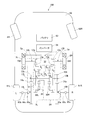
- the electric vehicle AM shown in FIG. 7 is a rear wheel drive system, and includes a chassis 60, drive wheels 61L and 61R as rear wheels, front wheels 62L and 62R, and a two-motor vehicle drive device 1 according to the present invention.
- a battery 63, an inverter 64, and the like are provided.
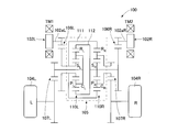
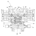
- the gear structure of the vehicle drive device 1 is shown with the skeleton figure.
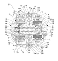
- a vehicle drive device 1 shown in FIG. 1 includes two electric motors 2L and 2R that are mounted on a vehicle and can be controlled independently, and left and right drive wheels 61L and 61R and two electric motors 2L and 2R. 2 left and right reduction gears 3L and 3R provided between them.
- the driving torque of the two-motor type vehicle drive device 1 is transmitted to the left and right drive wheels 61L and 61R via a drive shaft composed of constant velocity joints 65a and 65b and an intermediate shaft 65c.
- a front wheel drive system or a four wheel drive system may be used in addition to the rear wheel drive system shown in FIG.
- the vehicle drive device shown in FIG. 1 may be mounted on both the front wheels or the rear wheels, or may be mounted on one of them, and the other may be another device such as an engine-driven gear device. It may be a drive device.
- the left and right electric motors 2L and 2R in the two-motor type vehicle drive device 1 use electric motors having the same maximum output and the same output characteristics, and are housed in motor housings 4L and 4R as shown in FIG. Has been.
- the motor housings 4L and 4R include cylindrical motor housing bodies 4aL and 4aR, outer walls 4bL and 4bR that close the outer surfaces of the motor housing bodies 4aL and 4aR, and reduction gears on the inner surfaces of the motor housing bodies 4aL and 4aR. It consists of inner walls 4cL and 4cR separated from 3L and 3R. The inner walls 4cL and 4cR are provided with openings through which the motor shaft 5a is drawn.
- the electric motors 2 ⁇ / b> L and 2 ⁇ / b> R are of a radial gap type in which a stator 6 is provided on the inner peripheral surface of the motor housing main body 4 aL and 4 aR, and a rotor 5 is provided with a gap in the inner periphery of the stator 6. I am using something.
- the electric motors 2L and 2R may be axial gap types.
- the rotor 5 has a motor shaft 5a in the center, and the motor shaft 5a is drawn from the openings of the inner walls 4cL and 4cR of the motor housing main bodies 4aL and 4aR to the reduction gears 3L and 3R, respectively.
- a seal member 7 is provided between the periphery of the inner side walls 4cL and 4cR of the motor housing bodies 4aL and 4aR and the motor shaft 5a.
- the motor shaft 5a is rotatably supported by the rolling bearings 8a and 8b on the inner walls 4cL and 4cR and the outer walls 4bL and 4bR of the motor housing bodies 4aL and 4aR (see FIG. 1).
- the bearings 8a and 8b are the same, but different sizes may be combined.
- a reduction gear housing 9 that accommodates two reduction gears 3L and 3R provided in parallel on the left and right is divided into three pieces in a direction perpendicular to the gear shafts of the reduction gears 3L and 3R, as shown in FIG.
- the housing 9a has a three-piece structure including left and right side housings 9bL and 9bR fixed to both side surfaces of the central housing 9a.
- the left and right side housings 9bL and 9bR are fixed to the openings on both sides of the central housing 9a by a plurality of bolts (not shown).
- a plurality of bolts 10 are used to fix side faces 9bL and 9bR of the reduction gear housing 9 on the side of the outboard side (outside the vehicle body) and the inner side walls 4cL and 4cR of the motor housing bodies 4aL and 4aR of the electric motors 2L and 2R.
- the two electric motors 2L and 2R are fixedly arranged on the left and right sides of the reduction gear housing 9 (see FIG. 1).
- the central housing 9a is provided with a partition wall 11 in the center.
- the speed reducer housing 9 is divided into left and right parts by the partition wall 11, and independent left and right accommodation chambers for accommodating the two speed reducers 3L and 3R are provided in parallel.
- the reduction gears 3L and 3R are provided symmetrically and have large input gear shafts 12L and 12R having an input gear 12a to which power is transmitted from the motor shaft 5a, and the input gear 12a.
- Intermediate gear shafts 13L and 13R having both an output side small gear 13b meshing with an input side external gear 13a and an output gear 14a, and an output gear 14a.
- the constant velocity joint 65a is pulled out from the speed reducer housing 9.
- 65 is a parallel shaft gear reducer including output gear shafts 14L and 14R that transmit torque to drive wheels 61L and 61R (see FIG. 7) via an intermediate shaft 65c (see FIG. 7).
- the input gear shafts 12L and 12R, the intermediate gear shafts 13L and 13R, and the output gear shafts 14L and 14R of the left and right reduction gears 3L and 3R are coaxially arranged.
- Both ends of the input gear shafts 12L and 12R of the reduction gears 3L and 3R are respectively connected to bearing fitting holes 16a formed on both left and right sides of the partition wall 11 of the central housing 9a and bearing fitting holes 16b formed on the side housings 9bL and 9bR. It is rotatably supported via rolling bearings 17a and 17b.
- the bearing fitting holes 16a and 16b have a stepped shape having a wall portion with which the outer rings of the rolling bearings 17a and 17b abut. In FIG. 1, the rolling bearings 17a and 17b are the same, but they may be combined in different sizes.
- the end portions on the outboard side of the input gear shafts 12L, 12R are drawn outward from the openings provided in the side housings 9bL, 9bR, and between the openings and the outer ends of the input gear shafts 12L, 12R. Is provided with an oil seal 18 to prevent leakage of the lubricating oil sealed in the speed reducer housing 9.
- the input gear shafts 12L and 12R have a hollow structure, and end portions of the motor shaft 5a are inserted into the hollow input gear shafts 12L and 12R.
- the input gear shafts 12L, 12R and the motor shaft 5a are coupled by splines (including serrations, the same applies hereinafter).
- At least one or more intermediate gear shafts 13L and 13R are arranged.
- the intermediate gear shafts 13L and 13R have a pair of intermediate gear shafts 13L and 13R.
- the intermediate gear shafts 13L and 13R constitute a stepped gear shaft having an input side external gear 13a meshing with the input gear 12a on the outer peripheral surface and an output side small gear 13b meshing with the output gear 14a.
- rolling bearings 20a and 20b are fitted into bearing fitting holes 19a formed on both surfaces of the partition wall 11 of the central housing 9a and bearing fitting holes 19b formed on the side housings 9bL and 9bR. Is supported through.
- the bearing fitting holes 19a and 19b have a stepped shape with a wall portion with which the outer rings of the rolling bearings 20a and 20b come into contact.
- the bearing fitting hole 19a has a first coupling member 31 and a second coupling which will be described later. It penetrates so that member 32 may pass.
- the rolling bearings 20a and 20b have different sizes, but they may be combined with each other.
- the intermediate gear shafts 13L and 13R arranged on the same axis are connected to the intermediate gear shafts 13L and 13R so that the drive torque applied from the two electric motors 2L and 2R is a torque difference between the left and right drive wheels 61L and 61R.
- a gear device 30 for amplifying and distributing the signal is incorporated.
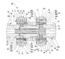
- the gear device 30 is composed of two planetary gear mechanisms 30L and 30R with three elements and two degrees of freedom, which are coaxially combined with a pair of left and right intermediate gear shafts 13L and 13R arranged coaxially.
- the planetary gear mechanisms 30L and 30R constituting the gear device 30 include internal gears R L and R R and internal gears R L and R R incorporated in the large-diameter input side external gear 13a of the intermediate gear shafts 13L and 13R, respectively.
- a plurality of planetary gears P L arranged equally in the circumferential direction as revolving gears meshed with the sun gears S L , S R and the internal gears R L , R R and the sun gears S L , S R provided coaxially with each other.
- a first coupling member 31 that couples the other sun gear S R (the right side of the figure in FIG. 1) with one sun gear S L (the left side of the figure in FIG. 1) and the other sun gear S R a planet carrier C R second coupling member 32 for coupling the (right side in FIG. in FIG.
- the planetary gear mechanisms 30L and 30R constituting the gear device 30 are incorporated only in any one of the pair of intermediate gear shafts 13L and 13R.
- the input-side external gear 13a connected to the internal gears R L , R R is an output-side small gear 13b provided on the drive-side intermediate gear shafts 13L, 13R among the plural pairs of intermediate gear shafts 13L, 13R, or
- An output-side small-diameter gear 13b that is arranged so as to mesh with the input gear 12a of the input gear shafts 12L and 12R and is coaxial with the planetary gear mechanisms 30L and 30R is formed of a plurality of pairs of intermediate gear shafts 13L and 13R.
- the planetary carriers C L and C R are composed of a carrier pin 33 that supports the planetary gears P L and P R , and an outboard side carrier flange that is connected to the outboard side end of the carrier pin 33. 34a and an inboard carrier flange 34b connected to the inboard side end.
- the carrier flange 34a on the outboard side includes a hollow shaft portion 35 extending toward the outboard side, and the end portion on the outboard side of the hollow shaft portion 35 is formed on the side housings 9bL and 9bR of the speed reducer housing 9. It is supported by the fitting hole 19b via the rolling bearing 20b (refer FIG. 1).
- the carrier flange 34b on the inboard side includes a hollow shaft portion 36 extending toward the inboard side, and an end portion on the inboard side of the hollow shaft portion 36 is formed in a bearing fitting hole formed in the partition wall 11 of the central housing 9a. It is supported by 19a via the rolling bearing 20a (refer FIG. 1).
- the output-side small-diameter gear 13b is integrally formed on the outer peripheral surface of the hollow shaft portion 35 of the carrier flange 34a.
- the planetary gears P L and P R are supported by the carrier pin 33 via the needle roller bearing 37.
- each of the carrier flanges 34a, 34b facing surface and a planetary gear P L of, inserting the thrust plate (not shown) between the P R, the planetary gear P L, even working to smooth rotation of the P R Good.
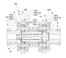
- a bearing 39 is disposed between the outer peripheral surfaces of the carrier flanges 34a and 34b and the internal gears R L and R R.
- a deep groove ball bearing is adopted as the bearing 39 for supporting the internal gears R L and R R on the carrier flanges 34a and 34b.
- the deep groove ball bearing includes an outer ring 39a, an inner ring 39b, and a rolling element 39c.
- the raceway surface of the outer ring 39a is used as the inner diameter surface of the internal gears R L and R R. Formed directly.
- the outer ring 39a By forming the raceway surface of the outer ring 39a directly on the inner diameter surface of the inner gears R L and R R , the outer ring 39a has a thickness corresponding to the thickness of the outer ring than when the outer ring of a separate part is incorporated in the inner diameter surface of the inner gears R L and R R The radial dimension can be reduced.
- gears such as the internal gears R L and R R
- a case-hardened steel that has been subjected to surface hardening and quenching is used in order to sufficiently secure the tooth surface strength and tooth root strength of the teeth.
- bearings that support the rotation of gears also need to withstand high surface pressure generated on the rolling elements and raceways by the load.
- high-carbon chromium alloy steel that has been subjected to core quenching or surface-hardened steel Hardened and hardened. That is, both the gear and the bearing need to have sufficient hardness (for example, a surface hardness of 58 HRC or more) by quenching.
- the internal gears R L and R R are, for example, case-hardened steel, and carburized and quenched as a heat treatment, and the surface hardness of the tooth portion and the bearing raceway surface is It is secured at 58HRC or higher.
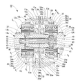
- a deep groove ball bearing is adopted as the bearing 39 for supporting the internal gears R L and R R on the carrier flanges 34a and 34b, as in the embodiment shown in FIGS.
- the raceway surface corresponding to the inner ring 39b of the bearing is formed directly on the outer diameter surfaces of the carrier flanges 34a and 34b.
- the planetary carriers C L and C R provided with the carrier flanges 34a and 34b are, for example, medium carbon steel, and the bearing raceway surface is subjected to induction hardening as a heat treatment, and the surface hardness is secured to 58 HRC or more. Yes.
- the teeth of the output-side small-diameter gear 13b formed on the planetary carriers C L and C R are also heat-treated in the same manner. A portion to be induction-hardened is indicated by a thick dashed line in FIG.
- the rolling bearing 39 is the same on the outboard side and the inboard side, but a combination of different forms may be used. That is, the bearing on the outboard side directly forms the raceway surface of the outer ring 39a on the inner diameter surface of the internal gears R L and R R as shown in FIGS. 1 and 2, and the bearing on the inboard side is the inner ring 39a as shown in FIG.
- the raceway surface may be formed directly on the outer diameter surface of the carrier flanges 34a, 34b.
- the bearing on the inboard side directly forms the raceway surface of the outer ring 39a on the inner diameter surface of the internal gears R L and R R
- the bearing on the outboard side forms the raceway surface of the inner ring 39a on the carrier flanges 34a and 34b. You may form directly on an outer diameter surface.
- the size of the bearing may be different between the bearing on the outboard side and the bearing on the inboard side.
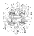
- FIG. 4 employs a cylindrical roller bearing with a cage as the bearing 39 for supporting the internal gears R L and R R on the carrier flanges 34a and 34b.
- the raceway surface of the outer ring 39a is an internal gear R L, are directly formed on the inner diameter surface of the R R, further, the raceway surface of the inner ring 39b is also directly formed on the outer peripheral surface of the carrier flange 34a, 34b Has been.
- a step is provided at the inner end of the raceway surface of the outer ring 39a to restrict the rolling element 39c from moving.
- a thrust ring 39d is provided in the vicinity of the outside of the raceway surface of the inner ring 39b. The thrust ring 39d is regulated so as not to drop off by a retaining ring 39e provided further outside. As a result, the rolling element 39c is restricted from moving in the axial direction by the step and the thrust ring 39d, and is prevented from falling off the bearing 39.
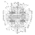
- the embodiment shown in FIG. 5 employs a deep groove ball bearing as the bearing 39 for supporting the internal gears R L and R R on the carrier flanges 34a and 34b as in the embodiment shown in FIGS.
- the bearings 39 are provided on both the outboard side and the inboard side.
- the cantilever is supported only by the bearing 39 on the board side.
- the raceway surface of the outer ring 39a is formed directly on the inner diameter surface of the internal gears R L and R R
- the raceway surface of the inner ring 39b is formed on the carrier flange 34b on the inboard side. It is formed directly on the outer peripheral surface.
- the bearings 39 are provided in a single row, but may be in a double row (not shown).
- a cylindrical roller bearing can be adopted as in the embodiment shown in FIG.
- the outboard side bearing 39 is abolished and is cantilevered only by the inboard side bearing 39, but the inboard side bearing 39 is abolished and the outboard side bearing 39 is supported. You may make it cantilever-support only by 39 (illustration omitted).
- FIG. 6AB employs a plain bearing as the bearing 39 for supporting the internal gears R L and R R on the carrier flanges 34a and 34b.
- the sliding bearing is attached by fitting to the stepped portion provided on the outer peripheral surface of the carrier flanges 34a, 34b, and the sliding surface of the sliding bearing is attached to the inner diameter surface of the internal gears R L , R R. Is formed directly.
- the sliding surfaces of the inner diameter surfaces of the internal gears R L and R R are secured by heat treatment.
- axial and circumferential oil grooves 39f are formed on the outer peripheral surface of the slide bearing so that lubricating oil can be supplied to the sliding surface.
- the collar 40 is disposed between the inboard carrier flange 34b and the rolling bearing 20a that supports the hollow shaft portion 36 of the inboard carrier flange 34b.
- the first coupling member 31 and the second coupling member 32 that couple the two planetary gear mechanisms 30L and 30R that constitute the gear device 30 of the vehicle drive device 1 are the speed reducer housing 9.
- the central housing 9a is incorporated through the partition wall 11 that partitions the left and right.
- the first coupling member 31 and the second coupling member 32 are arranged coaxially, and one coupling member (the second coupling member 32 in each embodiment of FIGS. 1 to 6) is a hollow shaft and the other coupling
- the member (the first coupling member 31 in each embodiment of FIGS. 1 to 6) has a double structure composed of a shaft inserted through the hollow shaft.
- the end portion of the right side of the planetary gear mechanism 30R side in the second coupling member 32 consists of a hollow shaft, and the hollow shaft portion 36 of the carrier flange 34b on the inboard side of the planet carrier C R the spline 41 is provided, it is connected by spline fitting to the second coupling member 32 the planet carrier C R.
- the end portion of the left planetary gear mechanism 30L side of the first coupling member 31, the spline 42 in the hollow shaft portion 35 of the carrier flange 34a on the outboard side of the planet carrier C L provided, the first coupling member 31 to the planet carrier C L are connected by spline fitting.
- the two planetary gear mechanisms 30L, first coupling member 31 of the 30R and a second binding member 32 by connecting the splined to the planet carrier C L and the planet carrier C R, two The planetary gear mechanism can be divided into left and right, and can be incorporated into the three-piece reduction gear housing 9 from the left and right in the same manner as other reduction gear shafts.
- End of the planet carrier C L of the second coupling member 32 has, on its outer peripheral surface, the external gear meshing with the planetary gears P L of the left planetary gear mechanism is formed, the sun the external gear of the left planetary gear mechanism A gear S L is configured.
- the first coupling member 31 inserted through the second coupling member 32 constituted by a hollow shaft has a large diameter portion 43 at an end portion on the right planetary gear mechanism 30R side, and an outer peripheral surface of the large diameter portion 43 is provided. , external gear meshing with the planetary gears P R of the right planetary gear mechanism 30R is formed, the outer gear constitutes the sun gear S R of the right planetary gear mechanism 30R.
- the maximum diameter of the sun gear S R which (in each embodiment the coupling member 31) coupling members on the inner diameter side are connected with the outer diameter side coupling member by (in the embodiments in which the second coupling member 32) is set smaller than the minimum diameter of the spline hole of the inner surface of the hollow shaft portion 36 of the carrier flange 34b on the inboard side of the planet carrier C R for mating is the inner diameter side It is possible to easily incorporate the coupling member (the first coupling member 31 in each embodiment).
- a collar 44 and a collar 44 are provided between the outer peripheral surface of the inner diameter side coupling member (first coupling member 31 in each embodiment) and the inner peripheral surface of the outer diameter side coupling member (second coupling member 32). Needle roller bearings 45 and 46 are interposed at both ends.
- the first coupling member 31 and the second coupling member 32 and the planetary carriers C L and C R are fitted (splines 42 and 41) with a fitting tolerance that can be slid in the axial direction.
- the axial movement of the first coupling member 31 and the second coupling member 32 and the planetary carriers C L and C R due to the sliding movement of the spline (splines 42 and 41) is caused by the outer diameter side coupling member (each implementation).
- the load is supported by providing thrust bearings 47 and 48 at both ends of the second coupling member 32).
- the coupling member (the first coupling member 31 in each embodiment) on the inner diameter side of the dual-structure shaft that couples the two planetary gear mechanisms 30L and 30R is a coupling member (the first coupling member 31 in each embodiment) and the planet.
- the coupling member (the first coupling member 31 in each embodiment) on the inner diameter side of the double-structure shaft that couples the two planetary gear mechanisms 30L and 30R includes the tooth surfaces of the sun gears S L and S R , the planetary gear P L, the tooth surfaces of the P R, in order to supply the lubricating oil, etc, is provided an oil supply hole 50 to the axis.
- the thrust bearings 47 and 48 at both ends of the outer diameter side coupling member (second coupling member 32 in each embodiment) are positioned. Radial oil supply passages 51 and 52 are provided.
- the output gear shafts 14L and 14R have a large-diameter output gear 14a, and are formed in bearing fitting holes 53a formed on both surfaces of the partition wall 11 of the central housing 9a and bearing fitting holes 53b formed on the side housings 9bL and 9bR. It is supported by rolling bearings 54a and 54b.
- the bearing fitting holes 53a and 53b have a stepped shape having a wall portion with which the outer rings of the rolling bearings 54a and 54b come into contact. In FIG. 1, the rolling bearings 54a and 54b are the same, but they may be combined in different sizes.
- Outboard side ends of the output gear shafts 14L and 14R are drawn out of the reduction gear housing 9 from openings formed in the side housings 9bL and 9bR, and are pulled out to the outboard side of the output gear shafts 14L and 14R.
- the outer joint portion of the constant velocity joint 65a is splined to the outer peripheral surface of the end portion.
- the constant velocity joint 65a coupled to the output gear shafts 14L and 14R is connected to the drive wheels 61L and 61R via the intermediate shaft 65c and the constant velocity joint 65b (see FIG. 7).
- An oil seal 55 is provided between the end of the output gear shafts 14L and 14R on the outboard side and the opening formed in the side housings 9bL and 9bR, and leakage of the lubricating oil sealed in the speed reducer housing 9 and the outside Intrusion of muddy water from
- the gear configuration of the two-motor type vehicle drive device 1 of the embodiment shown in FIG. 1 is as shown in the skeleton diagram shown in FIG.
- the left and right electric motors 2 ⁇ / b> L and 2 ⁇ / b> R are operated by electric power supplied via an inverter 64 from a battery 63 mounted on the vehicle.
- the electric motors 2L and 2R are individually controlled by an electronic control device (not shown), and can generate and output different torques.
- the torque of the motor shaft 5a of the electric motors 2L and 2R is the gear ratio between the input gear shaft 12a of the input gear shafts 12L and 12R of the reduction gears 3L and 3R and the large-diameter input side external gear 13a of the intermediate gear shafts 13L and 13R. And transmitted to the internal gears R L and R R of the gear device 30.
- the output side small gear 13b of the intermediate gear shafts 13L and 13R meshes with the large diameter output gear 14a of the output gear shafts 14L and 14R via the gear device 30, and the number of teeth of the output side small gear 13b and the output gear 14a.
- the torque of the motor shafts 5a of the electric motors 2L and 2R is further increased by the ratio and output to the drive wheels 61L and 61R.
- the gear device 30 is configured by combining two planetary gear mechanisms 30L and 30R having the same three-element and two-degree-of-freedom with coaxial intermediate gear shafts 13L and 13R.
- the planetary gear mechanisms 30L and 30R are of a single pinion type.
- a planetary gear mechanism is used.
- the planetary gear mechanisms 30L and 30R are coaxially provided with sun gears S L and S R and internal gears R L and R R, and between these sun gears S L and S R and the internal gears R L and R R.
- a plurality of planetary gears P L, P R is close to the planetary gear P L, provided the P R rotatably supported by the sun gear S L, S R and the internal gear R L, on R R coaxial It is composed of planetary carriers C L and C R.
- the sun gear S L, S R and the planetary gears P L, P R is the external gear having gear teeth on the outer circumference
- the internal gear R L, R R is the internal gear having gear teeth on the inner peripheral is there.
- the planetary gears P L and P R mesh with the sun gears S L and S R and the internal gears R L and R.
- the gear device 30 includes the first planetary gear mechanism 30L having the sun gear S L , the planet carrier C L , the planet gear P L and the internal gear RL , and the sun gear S R and the planet carrier C.
- a second planetary gear mechanism 30R having a planetary gear P R and the internal gear R R is configured by combining coaxially.
- the torque TM1 generated by the electric motor 2L is transmitted to the intermediate gear shaft 13L by meshing the input gear 12a of the input gear shaft 12L and the input side external gear 13a, and the torque transmitted to the intermediate gear shaft 13L is It is transmitted to the output-side small gear 13b of the intermediate gear shaft 13L via the first planetary gear mechanism 30L, and the output-side small gear 13b of the intermediate gear shaft 13L and the output gear 14a of the output gear shaft 14L are engaged with each other to produce an output gear shaft.
- Drive torque TR is output from 14L to drive wheel 61L.
- the torque TM2 generated by the electric motor 2R is transmitted to the intermediate gear shaft 13R when the input gear 12a of the input gear shaft 12R and the input side external gear 13a are meshed, and the torque transmitted to the intermediate gear shaft 13R is the second torque. It is transmitted to the output-side small gear 13b of the intermediate gear shaft 13R via the planetary gear mechanism 30R, and the output-side small gear 13b of the intermediate gear shaft 13R and the output gear 14a of the output gear shaft 14R are meshed to drive from the output gear shaft 14R.
- a driving torque TR is output to the wheel 61R.
- the outputs from the electric motors 2L and 2R are also given to the internal gears R L and R R of the two planetary gear mechanisms 30L and 30R, respectively, and the outputs from the first coupling member 31 and the second coupling member 32 are drive wheels. It is given to 61L and 61R.
- the 2nd coupling member 32 is comprised by the hollow shaft, the 1st coupling member 31 is penetrated in the inside, and the axis
- the first coupling member 31 has one end a rotation shaft of the (right end in the drawing) is the sun gear S R, the other end (left end in the drawing) are provided through the sun gear S L, connected to the planet carrier C L Has been.
- the second coupling member 32 is a hollow shaft, one end (left end in the drawing) has a rotation shaft of the sun gear S L, the other end (right end in the drawing) is connected to the planet carrier C R.
- the first planetary gear mechanisms 30L and 30R are coupled by the first coupling member 31 and the second coupling member 32.
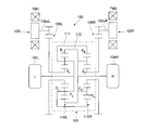
- the gear unit 30 is configured by combining two identical single pinion type planetary gear mechanisms 30L and 30R, it can be represented by two velocity diagrams as shown in FIG.
- the two speed diagrams are shifted up and down, the speed diagram of the left planetary gear mechanism 30L is shown on the upper side, and the speed diagram of the right planetary gear mechanism 30R is shown on the lower side.
- the torques TM1 and TM2 output from the electric motors 2L and 2R are respectively connected to the internal gears via the input side external gears 13a meshing with the input gears 12a of the input gear shafts 12L and 12R.
- the inputs from the electric motors 2L and 2R are the internal gears R L and R R
- the outputs to the drive wheels 61L and 61R are the sun gear S R and the carrier C L
- the sun gear S L and the carrier C R Become.
- the torque difference distributing mechanism is a gear unit 30 two planetary gear mechanism 30L which constitutes the connection of 30R the sun gear S L and the planet carrier C R, the sun gear S R And the planetary carrier C L , a connecting member having a larger diameter than the internal gears R L and R R is not required.
- the torque difference distribution mechanism can be made smaller than those of the prior art 1 and the prior art 2
- the vehicle drive device 1 for an electric vehicle incorporating the torque difference distribution mechanism can be made smaller and lighter.
- the vehicle on which the vehicle drive device 1 is mounted is not limited to an electric vehicle or a hybrid electric vehicle, but may be, for example, a fuel cell vehicle that uses the first electric motor 2L and the second electric motor 2R as driving sources. Good.
- the present invention is not limited to the embodiment described above, and can be implemented in various forms without departing from the gist of the present invention.
Landscapes
- Engineering & Computer Science (AREA)
- General Engineering & Computer Science (AREA)
- Mechanical Engineering (AREA)
- Manufacturing & Machinery (AREA)
- Retarders (AREA)
- Rolling Contact Bearings (AREA)
Applications Claiming Priority (2)
| Application Number | Priority Date | Filing Date | Title |
|---|---|---|---|
| JP2016-062491 | 2016-03-25 | ||
| JP2016062491A JP2017172775A (ja) | 2016-03-25 | 2016-03-25 | 車両駆動装置 |
Publications (1)
| Publication Number | Publication Date |
|---|---|
| WO2017163871A1 true WO2017163871A1 (ja) | 2017-09-28 |
Family
ID=59901232
Family Applications (1)
| Application Number | Title | Priority Date | Filing Date |
|---|---|---|---|
| PCT/JP2017/009156 Ceased WO2017163871A1 (ja) | 2016-03-25 | 2017-03-08 | 車両駆動装置 |
Country Status (2)
| Country | Link |
|---|---|
| JP (1) | JP2017172775A (enExample) |
| WO (1) | WO2017163871A1 (enExample) |
Cited By (1)
| Publication number | Priority date | Publication date | Assignee | Title |
|---|---|---|---|---|
| DE102020126666A1 (de) | 2020-10-12 | 2021-12-23 | Schaeffler Technologies AG & Co. KG | Mehrreihiges Lager für ein Getriebe |
Citations (7)
| Publication number | Priority date | Publication date | Assignee | Title |
|---|---|---|---|---|
| JPH11505309A (ja) * | 1995-05-09 | 1999-05-18 | アルファ ゲトリーベバウ ゲゼルシャフト ミット ベシュレンクテル ハフツング | 2段式遊星歯車装置 |
| JP2000310310A (ja) * | 1999-04-27 | 2000-11-07 | Ntn Corp | 軸受付きボールねじ機構および電動パワーステアリング装置 |
| JP2007211792A (ja) * | 2006-02-07 | 2007-08-23 | Ntn Corp | 車輪用軸受 |
| JP2008295173A (ja) * | 2007-05-23 | 2008-12-04 | Honda Motor Co Ltd | 動力装置 |
| JP2009203526A (ja) * | 2008-02-27 | 2009-09-10 | Nsk Ltd | 転がり軸受 |
| JP2010236598A (ja) * | 2009-03-31 | 2010-10-21 | Jtekt Corp | ボールねじ装置 |
| JP2014206202A (ja) * | 2013-04-11 | 2014-10-30 | 日本精工株式会社 | シェル型ニードル軸受 |
-
2016
- 2016-03-25 JP JP2016062491A patent/JP2017172775A/ja active Pending
-
2017
- 2017-03-08 WO PCT/JP2017/009156 patent/WO2017163871A1/ja not_active Ceased
Patent Citations (7)
| Publication number | Priority date | Publication date | Assignee | Title |
|---|---|---|---|---|
| JPH11505309A (ja) * | 1995-05-09 | 1999-05-18 | アルファ ゲトリーベバウ ゲゼルシャフト ミット ベシュレンクテル ハフツング | 2段式遊星歯車装置 |
| JP2000310310A (ja) * | 1999-04-27 | 2000-11-07 | Ntn Corp | 軸受付きボールねじ機構および電動パワーステアリング装置 |
| JP2007211792A (ja) * | 2006-02-07 | 2007-08-23 | Ntn Corp | 車輪用軸受 |
| JP2008295173A (ja) * | 2007-05-23 | 2008-12-04 | Honda Motor Co Ltd | 動力装置 |
| JP2009203526A (ja) * | 2008-02-27 | 2009-09-10 | Nsk Ltd | 転がり軸受 |
| JP2010236598A (ja) * | 2009-03-31 | 2010-10-21 | Jtekt Corp | ボールねじ装置 |
| JP2014206202A (ja) * | 2013-04-11 | 2014-10-30 | 日本精工株式会社 | シェル型ニードル軸受 |
Cited By (1)
| Publication number | Priority date | Publication date | Assignee | Title |
|---|---|---|---|---|
| DE102020126666A1 (de) | 2020-10-12 | 2021-12-23 | Schaeffler Technologies AG & Co. KG | Mehrreihiges Lager für ein Getriebe |
Also Published As
| Publication number | Publication date |
|---|---|
| JP2017172775A (ja) | 2017-09-28 |
Similar Documents
| Publication | Publication Date | Title |
|---|---|---|
| WO2017141607A1 (ja) | 車両駆動装置 | |
| US11618318B2 (en) | Transmission having a torque vectoring superposition unit | |
| JP2017203503A (ja) | 車両駆動装置 | |
| JP6290342B1 (ja) | 左右輪駆動装置の制御装置 | |
| US11207984B2 (en) | Drive source control device | |
| JP2018155310A (ja) | 四輪駆動車両 | |
| JP2017145931A (ja) | 車両駆動装置 | |
| JP2018039396A (ja) | 2モータ車両駆動装置 | |
| JP2018054053A (ja) | 車両用駆動装置 | |
| WO2018034099A1 (ja) | 車両駆動装置 | |
| JP2018155327A (ja) | 車両駆動装置 | |
| JP2018093612A (ja) | モータ制御装置およびこのモータ制御装置を備えた車両 | |
| JP2017141889A (ja) | 車両駆動装置 | |
| WO2017163871A1 (ja) | 車両駆動装置 | |
| WO2017141617A1 (ja) | 車両駆動装置 | |
| JP2017180559A (ja) | 車両駆動装置 | |
| JP2017061959A (ja) | 車両駆動装置 | |
| JP2018048686A (ja) | 車両駆動装置 | |
| JP6170580B1 (ja) | 車両駆動装置 | |
| JP2018105325A (ja) | 左右輪駆動装置の異常検出装置、異常検出方法およびこの異常検出装置を備えた車両 | |
| JP2017145942A (ja) | 車両駆動装置 | |
| JP6647935B2 (ja) | 遊星歯車装置及びそれを用いた車両駆動装置 | |
| WO2018012189A1 (ja) | 車両駆動装置 | |
| WO2017068913A1 (ja) | 車両駆動装置 | |
| CN109804181B (zh) | 驱动源控制装置和具有该驱动源控制装置的车辆 |
Legal Events
| Date | Code | Title | Description |
|---|---|---|---|
| NENP | Non-entry into the national phase |
Ref country code: DE |
|
| 121 | Ep: the epo has been informed by wipo that ep was designated in this application |
Ref document number: 17769916 Country of ref document: EP Kind code of ref document: A1 |
|
| 122 | Ep: pct application non-entry in european phase |
Ref document number: 17769916 Country of ref document: EP Kind code of ref document: A1 |