WO2017163871A1 - Vehicle drive device - Google Patents
Vehicle drive device Download PDFInfo
- Publication number
- WO2017163871A1 WO2017163871A1 PCT/JP2017/009156 JP2017009156W WO2017163871A1 WO 2017163871 A1 WO2017163871 A1 WO 2017163871A1 JP 2017009156 W JP2017009156 W JP 2017009156W WO 2017163871 A1 WO2017163871 A1 WO 2017163871A1
- Authority
- WO
- WIPO (PCT)
- Prior art keywords
- gear
- bearing
- drive device
- planetary
- vehicle drive
- Prior art date
Links
Images


Classifications
-
- F—MECHANICAL ENGINEERING; LIGHTING; HEATING; WEAPONS; BLASTING
- F16—ENGINEERING ELEMENTS AND UNITS; GENERAL MEASURES FOR PRODUCING AND MAINTAINING EFFECTIVE FUNCTIONING OF MACHINES OR INSTALLATIONS; THERMAL INSULATION IN GENERAL
- F16C—SHAFTS; FLEXIBLE SHAFTS; ELEMENTS OR CRANKSHAFT MECHANISMS; ROTARY BODIES OTHER THAN GEARING ELEMENTS; BEARINGS
- F16C19/00—Bearings with rolling contact, for exclusively rotary movement
- F16C19/02—Bearings with rolling contact, for exclusively rotary movement with bearing balls essentially of the same size in one or more circular rows
- F16C19/14—Bearings with rolling contact, for exclusively rotary movement with bearing balls essentially of the same size in one or more circular rows for both radial and axial load
- F16C19/18—Bearings with rolling contact, for exclusively rotary movement with bearing balls essentially of the same size in one or more circular rows for both radial and axial load with two or more rows of balls
-
- F—MECHANICAL ENGINEERING; LIGHTING; HEATING; WEAPONS; BLASTING
- F16—ENGINEERING ELEMENTS AND UNITS; GENERAL MEASURES FOR PRODUCING AND MAINTAINING EFFECTIVE FUNCTIONING OF MACHINES OR INSTALLATIONS; THERMAL INSULATION IN GENERAL
- F16C—SHAFTS; FLEXIBLE SHAFTS; ELEMENTS OR CRANKSHAFT MECHANISMS; ROTARY BODIES OTHER THAN GEARING ELEMENTS; BEARINGS
- F16C19/00—Bearings with rolling contact, for exclusively rotary movement
- F16C19/22—Bearings with rolling contact, for exclusively rotary movement with bearing rollers essentially of the same size in one or more circular rows, e.g. needle bearings
- F16C19/24—Bearings with rolling contact, for exclusively rotary movement with bearing rollers essentially of the same size in one or more circular rows, e.g. needle bearings for radial load mainly
-
- F—MECHANICAL ENGINEERING; LIGHTING; HEATING; WEAPONS; BLASTING
- F16—ENGINEERING ELEMENTS AND UNITS; GENERAL MEASURES FOR PRODUCING AND MAINTAINING EFFECTIVE FUNCTIONING OF MACHINES OR INSTALLATIONS; THERMAL INSULATION IN GENERAL
- F16C—SHAFTS; FLEXIBLE SHAFTS; ELEMENTS OR CRANKSHAFT MECHANISMS; ROTARY BODIES OTHER THAN GEARING ELEMENTS; BEARINGS
- F16C33/00—Parts of bearings; Special methods for making bearings or parts thereof
- F16C33/30—Parts of ball or roller bearings
- F16C33/58—Raceways; Race rings
- F16C33/64—Special methods of manufacture
-
- F—MECHANICAL ENGINEERING; LIGHTING; HEATING; WEAPONS; BLASTING
- F16—ENGINEERING ELEMENTS AND UNITS; GENERAL MEASURES FOR PRODUCING AND MAINTAINING EFFECTIVE FUNCTIONING OF MACHINES OR INSTALLATIONS; THERMAL INSULATION IN GENERAL
- F16H—GEARING
- F16H48/00—Differential gearings
- F16H48/06—Differential gearings with gears having orbital motion
- F16H48/10—Differential gearings with gears having orbital motion with orbital spur gears
-
- F—MECHANICAL ENGINEERING; LIGHTING; HEATING; WEAPONS; BLASTING
- F16—ENGINEERING ELEMENTS AND UNITS; GENERAL MEASURES FOR PRODUCING AND MAINTAINING EFFECTIVE FUNCTIONING OF MACHINES OR INSTALLATIONS; THERMAL INSULATION IN GENERAL
- F16H—GEARING
- F16H48/00—Differential gearings
- F16H48/38—Constructional details
Definitions
- the present invention relates to a vehicle drive device capable of amplifying a torque difference and transmitting drive torque from two independent drive sources to left and right drive wheels.
- electric motors are arranged on the left and right drive wheels, respectively, and each electric motor is controlled independently to give an appropriate drive torque difference between the left and right wheels, thereby controlling the turning moment of the vehicle It is known to do.
- it is effective to generate a large difference in driving torque between the left and right drive wheels in order to achieve smooth turning of the vehicle and to suppress changes in vehicle behavior such as extreme understeer and extreme oversteer There is. For this reason, it is desirable to amplify the difference between the torques output from the two electric motors and transmit them to the left and right drive wheels.
- Patent Document 1 a differential that is a torque difference amplifying mechanism in which two planetary gear structures with three elements and two degrees of freedom are coaxially arranged between two drive sources and left and right drive wheels.
- a vehicle drive device comprising the device is disclosed.
- the vehicle driving device disclosed in FIG. 5A of Patent Document 1 (hereinafter referred to as Conventional Technology 1) has a configuration as shown in the skeleton diagram shown in FIG.
- the vehicle drive device 100 includes left and right electric motors 102L and 102R mounted on the vehicle, left drive wheels 104L and right drive wheels 104R, a differential device 105 and reduction gear trains 106L and 106R provided therebetween. , 107L, 107R.
- the electric motor 102L and the electric motor 102R operate with electric power from a battery (not shown) mounted on the vehicle, are individually controlled by an electronic control device (not shown), and can generate and output different torques. .
- the output shaft 102aL of the electric motor 102L and the output shaft 102aR of the electric motor 102R are connected to the coupling members 111 and 112 of the differential device 105 through the reduction gear trains 106L and 106R, respectively.
- the output from the differential device 105 is given to the left and right drive wheels 104L, 104R via the reduction gear trains 107L, 107R.
- the differential device 105 is configured by combining two identical planetary gear mechanisms 110L and 110R with three elements and two degrees of freedom on the same axis.
- the single-pinion type planetary gear mechanism includes a sun gear S L , S R and internal gears R L , R R provided on the same axis, and these sun gears S L , S R and internal gears R L , R R.
- a plurality of planetary gears P L and P R and planetary gears P L and P R are rotatably supported, and are provided coaxially with the sun gears S L and S R and the internal gears R L and R R.
- was planet carrier C L is composed of a C R
- the planetary gear P L, P R is engaged the sun gear S L, S R and the internal gear R L, in the R R.
- the sun gear S L, S R and the planetary gears P L, P R is the external gear having gear teeth on the outer circumference
- the internal gear R L, R R is the internal gear having gear teeth on the inner peripheral is there.
- the differential 105 includes a first planetary gear mechanism 110L having a sun gear S L , a planet carrier C L , a planetary gear P L, and an internal gear RL , as well as a sun gear S R , a planetary gear.
- carrier C R, and a second planetary gear mechanism 110R having a planetary gear P R and the internal gear R R is configured by combining coaxially.
- the sun gear S L of the first planetary gear mechanism 110L and the internal gear R R of the second planetary gear mechanism 110R is coupled by a first coupling member 111, and the internal gear R L of the first planetary gear mechanism 110L second
- the sun gear S R of the planetary gear mechanism 110R is coupled by the second coupling member 112.
- the torque TM1 generated by the electric motor 102L is input to the first coupling member 111 via the reduction gear train 106L, and the torque TM2 generated by the electric motor 102R is input to the second coupling member 112 by the reduction gear train 106R. Is input through. Further, the planet carrier C R of the planetary carrier C L and the second planetary gear mechanism 110R of the first planetary gear mechanism 110L, respectively reduction gear train 107L, through 107R left and right drive wheels 104L, the output is connected to the 104R It is taken out.
- Patent Document 2 (hereinafter referred to as Conventional Technology 2) has a configuration as shown in the skeleton diagram shown in FIG.
- the vehicle drive device 100 is provided between a first electric motor 102L and a second electric motor 102R mounted on the vehicle, a left drive wheel 104L and a right drive wheel 104R, and these.
- a differential device 105 and reduction gear trains 106L and 106R are provided.
- the first electric motor 102L and the second electric motor 102R operate with electric power from a battery (not shown) mounted on the vehicle, and are individually controlled by an electronic control device (not shown) to generate different torques. Can be output.
- the output shaft 102aL of the first electric motor 102L and the output shaft 102aR of the second electric motor 102R are connected to the sun gears S L and S R of the differential device 105 via reduction gear trains 106L and 106R, respectively.
- the output from the differential device 105 is given to the left and right drive wheels 104L, 104R.
- the differential device 105 of the prior art 2 is configured by combining two identical planetary gear mechanisms 110L and 110R with three elements and two degrees of freedom on the same axis.
- the planetary gear mechanisms 110L and 110R for example, single-pinion type planetary gear mechanisms are employed.
- the first electric motor 102L torque TM1 generated in is input to the sun gear S L of the first planetary gear mechanism 110L via a reduction gear train 106L, torque TM2 generated by the second electric motor 102R is decelerated It is input to the sun gear S R of the second planetary gear mechanism 110R through a gear train 106R.
- first coupling member 111 and the second coupling member 112 are connected to the left and right drive wheels 104L and 104R, respectively, and outputs are taken out.
- the electric motor 102L input from 102R, the sun gear S L, the sun gear S R, and the drive wheels 104L, output to 104R, the carrier C L and the internal gear R R, and the carrier C R It becomes an internal gear R L.
- the vehicle drive device (prior application example 1) for which the applicant of this application has applied for a patent has the configuration shown in FIGS.
- Gear 300 one of the planet carrier C L and the other of the first coupling member 231 for coupling the sun gear S R, a second coupling member for coupling one of the sun gear S L and the other planet carrier C R 232, the first coupling member 231 and the second coupling member 232 are arranged coaxially, and among the first coupling member 231 and the second coupling member 232, the second coupling member 232 is a hollow shaft,
- the coupling member 231 has a shaft inserted through the hollow shaft, and the shaft passing between the two planetary gear mechanisms 300L and 300R has a double structure, and the internal gear R L of the planetary gear mechanisms 300L and 300R. , R R and the input gear 213 of the speed reduction mechanism are engaged with and connected to external gears 217 provided on the internal gears R L , R R.
- Patent Document 3 discloses a vehicle drive device (prior art 3) provided with a differential device that is a torque difference amplification mechanism.
- the vehicle drive device of Prior Art 3 includes first and second drive sources M 1 and M 2, left and right drive wheels WL and WR, both drive sources M 1 and M 2, A differential device 302 interposed between the drive wheels WL and WR.
- the differential device 302 includes a continuous pinion 320 having a plurality of planetary gears connected to one shaft, and a continuous pinion.
- the rotating mechanism includes sun gears 324 and 325 that mesh with the planetary gears 321 and 322 of 320, a carrier 323 that pivotally supports the continuous pinion 320, and an internal gear 327 that meshes with the planetary gear 322 of the continuous pinion 320. .
- a drive source M1, a drive source M2, and left and right drive wheels WL, WR are connected to the differential device 302.
- the drive source M1 is connected to the internal gear 327 via the hollow shaft 311, and the drive source M2 is connected to the hollow shaft 312.
- the left driving wheel WL is connected to the carrier 323 via the shaft 313L
- the right driving wheel WR is connected to the first sun gear 324 via the shaft 313R.
- the deep groove ball bearing 220 is disposed between the internal gears R L and R R and the planetary carriers C L and C R.
- the deep groove ball bearing 220 includes an inner ring 220a, a rolling element 220b, and an outer ring 220c.
- the bearing elements such as the inner ring 220a, the rolling element 220b, and the outer ring 220c are arranged between the inner gears R L and R R and the planetary carriers C L and C R. Since it is necessary to arrange them, the radial dimension increases by the thickness of the inner ring 220a and the outer ring 220c.
- the vehicle drive device is mounted on the vehicle body, it is advantageous to reduce the mounting space and secure a wide cabin space, and it is essential to reduce the size and weight of the gear device that amplifies the torque difference.
- an object of the present invention is to reduce the size in the radial direction of a torque difference amplification mechanism incorporated in a vehicle drive device.
- the present invention provides a three-element and two-degree-of-freedom planetary gear mechanism coaxially between two drive sources mounted on a vehicle and independently controllable and left and right drive wheels. Two combinations, a specific element of one planetary gear mechanism and a specific element of the other planetary gear mechanism are connected to each other by a first coupling member and a second coupling member to drive left and right from two driving sources.
- a differential device for amplifying and outputting a torque difference is provided on the ring, and the planetary gear mechanism is provided with an internal gear, a planet carrier provided coaxially with the internal gear, and provided coaxially with the internal gear.
- a vehicle drive device having a sun gear and a planetary gear as a revolving gear, an external gear as a speed reduction mechanism connected to the internal gear, and the internal gear supported by the planet carrier via a bearing
- the opposing surface of the internal gear and the planet carrier On at least one side, characterized in that the formation of the raceway surface of the bearing that is hardened.
- the bearing surface of the hardened bearing may be formed on the inner diameter surface of the internal gear, or the raceway surface of the hardened bearing may be formed on the outer diameter surface of the planet carrier.
- the material of the internal gear or planetary carrier is case-hardened steel, and the raceway surface of the bearing can be formed by carburizing and quenching.
- the material of the internal gear or planet carrier may be medium carbon steel, and the raceway surface of the bearing may be formed by induction hardening.
- the teeth of the internal gear may also be induction hardened.
- the bearing can be a deep groove ball bearing, and the cage of the deep groove ball bearing can be a resin crown.
- a cylindrical roller bearing with a cage may be used as the bearing, and a thrust washer may be disposed near the outer end of the raceway surface.
- a slide bearing may be used, and a stepped portion for arranging the slide bearing on the raceway surface may be provided.
- At least one of the outer ring and the inner ring is formed by directly forming the hardened raceway surface of the bearing on at least one of the opposing surfaces of the inner gear and the planetary carrier. Since it can be omitted, the radial dimension can be reduced by the thickness of the inner ring or the outer ring.
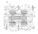
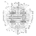
- FIG. 5 is an enlarged view showing another embodiment of the gear device surrounded by a two-dot chain line in FIG. 1.
- FIG. 6B is a partially enlarged view of the plain bearing taken along line bb in FIG. 6A.
- FIG. 10 is a skeleton diagram showing a gear configuration of a vehicle drive device according to Prior Art 3.
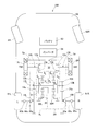
- the electric vehicle AM shown in FIG. 7 is a rear wheel drive system, and includes a chassis 60, drive wheels 61L and 61R as rear wheels, front wheels 62L and 62R, and a two-motor vehicle drive device 1 according to the present invention.
- a battery 63, an inverter 64, and the like are provided.
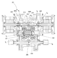
- the gear structure of the vehicle drive device 1 is shown with the skeleton figure.
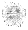
- a vehicle drive device 1 shown in FIG. 1 includes two electric motors 2L and 2R that are mounted on a vehicle and can be controlled independently, and left and right drive wheels 61L and 61R and two electric motors 2L and 2R. 2 left and right reduction gears 3L and 3R provided between them.
- the driving torque of the two-motor type vehicle drive device 1 is transmitted to the left and right drive wheels 61L and 61R via a drive shaft composed of constant velocity joints 65a and 65b and an intermediate shaft 65c.
- a front wheel drive system or a four wheel drive system may be used in addition to the rear wheel drive system shown in FIG.
- the vehicle drive device shown in FIG. 1 may be mounted on both the front wheels or the rear wheels, or may be mounted on one of them, and the other may be another device such as an engine-driven gear device. It may be a drive device.
- the left and right electric motors 2L and 2R in the two-motor type vehicle drive device 1 use electric motors having the same maximum output and the same output characteristics, and are housed in motor housings 4L and 4R as shown in FIG. Has been.
- the motor housings 4L and 4R include cylindrical motor housing bodies 4aL and 4aR, outer walls 4bL and 4bR that close the outer surfaces of the motor housing bodies 4aL and 4aR, and reduction gears on the inner surfaces of the motor housing bodies 4aL and 4aR. It consists of inner walls 4cL and 4cR separated from 3L and 3R. The inner walls 4cL and 4cR are provided with openings through which the motor shaft 5a is drawn.
- the electric motors 2 ⁇ / b> L and 2 ⁇ / b> R are of a radial gap type in which a stator 6 is provided on the inner peripheral surface of the motor housing main body 4 aL and 4 aR, and a rotor 5 is provided with a gap in the inner periphery of the stator 6. I am using something.
- the electric motors 2L and 2R may be axial gap types.
- the rotor 5 has a motor shaft 5a in the center, and the motor shaft 5a is drawn from the openings of the inner walls 4cL and 4cR of the motor housing main bodies 4aL and 4aR to the reduction gears 3L and 3R, respectively.
- a seal member 7 is provided between the periphery of the inner side walls 4cL and 4cR of the motor housing bodies 4aL and 4aR and the motor shaft 5a.
- the motor shaft 5a is rotatably supported by the rolling bearings 8a and 8b on the inner walls 4cL and 4cR and the outer walls 4bL and 4bR of the motor housing bodies 4aL and 4aR (see FIG. 1).
- the bearings 8a and 8b are the same, but different sizes may be combined.
- a reduction gear housing 9 that accommodates two reduction gears 3L and 3R provided in parallel on the left and right is divided into three pieces in a direction perpendicular to the gear shafts of the reduction gears 3L and 3R, as shown in FIG.
- the housing 9a has a three-piece structure including left and right side housings 9bL and 9bR fixed to both side surfaces of the central housing 9a.
- the left and right side housings 9bL and 9bR are fixed to the openings on both sides of the central housing 9a by a plurality of bolts (not shown).
- a plurality of bolts 10 are used to fix side faces 9bL and 9bR of the reduction gear housing 9 on the side of the outboard side (outside the vehicle body) and the inner side walls 4cL and 4cR of the motor housing bodies 4aL and 4aR of the electric motors 2L and 2R.
- the two electric motors 2L and 2R are fixedly arranged on the left and right sides of the reduction gear housing 9 (see FIG. 1).
- the central housing 9a is provided with a partition wall 11 in the center.
- the speed reducer housing 9 is divided into left and right parts by the partition wall 11, and independent left and right accommodation chambers for accommodating the two speed reducers 3L and 3R are provided in parallel.
- the reduction gears 3L and 3R are provided symmetrically and have large input gear shafts 12L and 12R having an input gear 12a to which power is transmitted from the motor shaft 5a, and the input gear 12a.
- Intermediate gear shafts 13L and 13R having both an output side small gear 13b meshing with an input side external gear 13a and an output gear 14a, and an output gear 14a.
- the constant velocity joint 65a is pulled out from the speed reducer housing 9.
- 65 is a parallel shaft gear reducer including output gear shafts 14L and 14R that transmit torque to drive wheels 61L and 61R (see FIG. 7) via an intermediate shaft 65c (see FIG. 7).
- the input gear shafts 12L and 12R, the intermediate gear shafts 13L and 13R, and the output gear shafts 14L and 14R of the left and right reduction gears 3L and 3R are coaxially arranged.
- Both ends of the input gear shafts 12L and 12R of the reduction gears 3L and 3R are respectively connected to bearing fitting holes 16a formed on both left and right sides of the partition wall 11 of the central housing 9a and bearing fitting holes 16b formed on the side housings 9bL and 9bR. It is rotatably supported via rolling bearings 17a and 17b.
- the bearing fitting holes 16a and 16b have a stepped shape having a wall portion with which the outer rings of the rolling bearings 17a and 17b abut. In FIG. 1, the rolling bearings 17a and 17b are the same, but they may be combined in different sizes.
- the end portions on the outboard side of the input gear shafts 12L, 12R are drawn outward from the openings provided in the side housings 9bL, 9bR, and between the openings and the outer ends of the input gear shafts 12L, 12R. Is provided with an oil seal 18 to prevent leakage of the lubricating oil sealed in the speed reducer housing 9.
- the input gear shafts 12L and 12R have a hollow structure, and end portions of the motor shaft 5a are inserted into the hollow input gear shafts 12L and 12R.
- the input gear shafts 12L, 12R and the motor shaft 5a are coupled by splines (including serrations, the same applies hereinafter).
- At least one or more intermediate gear shafts 13L and 13R are arranged.
- the intermediate gear shafts 13L and 13R have a pair of intermediate gear shafts 13L and 13R.
- the intermediate gear shafts 13L and 13R constitute a stepped gear shaft having an input side external gear 13a meshing with the input gear 12a on the outer peripheral surface and an output side small gear 13b meshing with the output gear 14a.
- rolling bearings 20a and 20b are fitted into bearing fitting holes 19a formed on both surfaces of the partition wall 11 of the central housing 9a and bearing fitting holes 19b formed on the side housings 9bL and 9bR. Is supported through.
- the bearing fitting holes 19a and 19b have a stepped shape with a wall portion with which the outer rings of the rolling bearings 20a and 20b come into contact.
- the bearing fitting hole 19a has a first coupling member 31 and a second coupling which will be described later. It penetrates so that member 32 may pass.
- the rolling bearings 20a and 20b have different sizes, but they may be combined with each other.
- the intermediate gear shafts 13L and 13R arranged on the same axis are connected to the intermediate gear shafts 13L and 13R so that the drive torque applied from the two electric motors 2L and 2R is a torque difference between the left and right drive wheels 61L and 61R.
- a gear device 30 for amplifying and distributing the signal is incorporated.
- the gear device 30 is composed of two planetary gear mechanisms 30L and 30R with three elements and two degrees of freedom, which are coaxially combined with a pair of left and right intermediate gear shafts 13L and 13R arranged coaxially.
- the planetary gear mechanisms 30L and 30R constituting the gear device 30 include internal gears R L and R R and internal gears R L and R R incorporated in the large-diameter input side external gear 13a of the intermediate gear shafts 13L and 13R, respectively.
- a plurality of planetary gears P L arranged equally in the circumferential direction as revolving gears meshed with the sun gears S L , S R and the internal gears R L , R R and the sun gears S L , S R provided coaxially with each other.
- a first coupling member 31 that couples the other sun gear S R (the right side of the figure in FIG. 1) with one sun gear S L (the left side of the figure in FIG. 1) and the other sun gear S R a planet carrier C R second coupling member 32 for coupling the (right side in FIG. in FIG.
- the planetary gear mechanisms 30L and 30R constituting the gear device 30 are incorporated only in any one of the pair of intermediate gear shafts 13L and 13R.
- the input-side external gear 13a connected to the internal gears R L , R R is an output-side small gear 13b provided on the drive-side intermediate gear shafts 13L, 13R among the plural pairs of intermediate gear shafts 13L, 13R, or
- An output-side small-diameter gear 13b that is arranged so as to mesh with the input gear 12a of the input gear shafts 12L and 12R and is coaxial with the planetary gear mechanisms 30L and 30R is formed of a plurality of pairs of intermediate gear shafts 13L and 13R.
- the planetary carriers C L and C R are composed of a carrier pin 33 that supports the planetary gears P L and P R , and an outboard side carrier flange that is connected to the outboard side end of the carrier pin 33. 34a and an inboard carrier flange 34b connected to the inboard side end.
- the carrier flange 34a on the outboard side includes a hollow shaft portion 35 extending toward the outboard side, and the end portion on the outboard side of the hollow shaft portion 35 is formed on the side housings 9bL and 9bR of the speed reducer housing 9. It is supported by the fitting hole 19b via the rolling bearing 20b (refer FIG. 1).
- the carrier flange 34b on the inboard side includes a hollow shaft portion 36 extending toward the inboard side, and an end portion on the inboard side of the hollow shaft portion 36 is formed in a bearing fitting hole formed in the partition wall 11 of the central housing 9a. It is supported by 19a via the rolling bearing 20a (refer FIG. 1).
- the output-side small-diameter gear 13b is integrally formed on the outer peripheral surface of the hollow shaft portion 35 of the carrier flange 34a.
- the planetary gears P L and P R are supported by the carrier pin 33 via the needle roller bearing 37.
- each of the carrier flanges 34a, 34b facing surface and a planetary gear P L of, inserting the thrust plate (not shown) between the P R, the planetary gear P L, even working to smooth rotation of the P R Good.
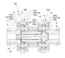
- a bearing 39 is disposed between the outer peripheral surfaces of the carrier flanges 34a and 34b and the internal gears R L and R R.
- a deep groove ball bearing is adopted as the bearing 39 for supporting the internal gears R L and R R on the carrier flanges 34a and 34b.
- the deep groove ball bearing includes an outer ring 39a, an inner ring 39b, and a rolling element 39c.
- the raceway surface of the outer ring 39a is used as the inner diameter surface of the internal gears R L and R R. Formed directly.
- the outer ring 39a By forming the raceway surface of the outer ring 39a directly on the inner diameter surface of the inner gears R L and R R , the outer ring 39a has a thickness corresponding to the thickness of the outer ring than when the outer ring of a separate part is incorporated in the inner diameter surface of the inner gears R L and R R The radial dimension can be reduced.
- gears such as the internal gears R L and R R
- a case-hardened steel that has been subjected to surface hardening and quenching is used in order to sufficiently secure the tooth surface strength and tooth root strength of the teeth.
- bearings that support the rotation of gears also need to withstand high surface pressure generated on the rolling elements and raceways by the load.
- high-carbon chromium alloy steel that has been subjected to core quenching or surface-hardened steel Hardened and hardened. That is, both the gear and the bearing need to have sufficient hardness (for example, a surface hardness of 58 HRC or more) by quenching.
- the internal gears R L and R R are, for example, case-hardened steel, and carburized and quenched as a heat treatment, and the surface hardness of the tooth portion and the bearing raceway surface is It is secured at 58HRC or higher.
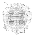
- a deep groove ball bearing is adopted as the bearing 39 for supporting the internal gears R L and R R on the carrier flanges 34a and 34b, as in the embodiment shown in FIGS.
- the raceway surface corresponding to the inner ring 39b of the bearing is formed directly on the outer diameter surfaces of the carrier flanges 34a and 34b.
- the planetary carriers C L and C R provided with the carrier flanges 34a and 34b are, for example, medium carbon steel, and the bearing raceway surface is subjected to induction hardening as a heat treatment, and the surface hardness is secured to 58 HRC or more. Yes.
- the teeth of the output-side small-diameter gear 13b formed on the planetary carriers C L and C R are also heat-treated in the same manner. A portion to be induction-hardened is indicated by a thick dashed line in FIG.
- the rolling bearing 39 is the same on the outboard side and the inboard side, but a combination of different forms may be used. That is, the bearing on the outboard side directly forms the raceway surface of the outer ring 39a on the inner diameter surface of the internal gears R L and R R as shown in FIGS. 1 and 2, and the bearing on the inboard side is the inner ring 39a as shown in FIG.
- the raceway surface may be formed directly on the outer diameter surface of the carrier flanges 34a, 34b.
- the bearing on the inboard side directly forms the raceway surface of the outer ring 39a on the inner diameter surface of the internal gears R L and R R
- the bearing on the outboard side forms the raceway surface of the inner ring 39a on the carrier flanges 34a and 34b. You may form directly on an outer diameter surface.
- the size of the bearing may be different between the bearing on the outboard side and the bearing on the inboard side.
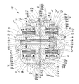
- FIG. 4 employs a cylindrical roller bearing with a cage as the bearing 39 for supporting the internal gears R L and R R on the carrier flanges 34a and 34b.
- the raceway surface of the outer ring 39a is an internal gear R L, are directly formed on the inner diameter surface of the R R, further, the raceway surface of the inner ring 39b is also directly formed on the outer peripheral surface of the carrier flange 34a, 34b Has been.
- a step is provided at the inner end of the raceway surface of the outer ring 39a to restrict the rolling element 39c from moving.
- a thrust ring 39d is provided in the vicinity of the outside of the raceway surface of the inner ring 39b. The thrust ring 39d is regulated so as not to drop off by a retaining ring 39e provided further outside. As a result, the rolling element 39c is restricted from moving in the axial direction by the step and the thrust ring 39d, and is prevented from falling off the bearing 39.
- the embodiment shown in FIG. 5 employs a deep groove ball bearing as the bearing 39 for supporting the internal gears R L and R R on the carrier flanges 34a and 34b as in the embodiment shown in FIGS.
- the bearings 39 are provided on both the outboard side and the inboard side.
- the cantilever is supported only by the bearing 39 on the board side.
- the raceway surface of the outer ring 39a is formed directly on the inner diameter surface of the internal gears R L and R R
- the raceway surface of the inner ring 39b is formed on the carrier flange 34b on the inboard side. It is formed directly on the outer peripheral surface.
- the bearings 39 are provided in a single row, but may be in a double row (not shown).
- a cylindrical roller bearing can be adopted as in the embodiment shown in FIG.
- the outboard side bearing 39 is abolished and is cantilevered only by the inboard side bearing 39, but the inboard side bearing 39 is abolished and the outboard side bearing 39 is supported. You may make it cantilever-support only by 39 (illustration omitted).
- FIG. 6AB employs a plain bearing as the bearing 39 for supporting the internal gears R L and R R on the carrier flanges 34a and 34b.
- the sliding bearing is attached by fitting to the stepped portion provided on the outer peripheral surface of the carrier flanges 34a, 34b, and the sliding surface of the sliding bearing is attached to the inner diameter surface of the internal gears R L , R R. Is formed directly.
- the sliding surfaces of the inner diameter surfaces of the internal gears R L and R R are secured by heat treatment.
- axial and circumferential oil grooves 39f are formed on the outer peripheral surface of the slide bearing so that lubricating oil can be supplied to the sliding surface.
- the collar 40 is disposed between the inboard carrier flange 34b and the rolling bearing 20a that supports the hollow shaft portion 36 of the inboard carrier flange 34b.
- the first coupling member 31 and the second coupling member 32 that couple the two planetary gear mechanisms 30L and 30R that constitute the gear device 30 of the vehicle drive device 1 are the speed reducer housing 9.
- the central housing 9a is incorporated through the partition wall 11 that partitions the left and right.
- the first coupling member 31 and the second coupling member 32 are arranged coaxially, and one coupling member (the second coupling member 32 in each embodiment of FIGS. 1 to 6) is a hollow shaft and the other coupling
- the member (the first coupling member 31 in each embodiment of FIGS. 1 to 6) has a double structure composed of a shaft inserted through the hollow shaft.
- the end portion of the right side of the planetary gear mechanism 30R side in the second coupling member 32 consists of a hollow shaft, and the hollow shaft portion 36 of the carrier flange 34b on the inboard side of the planet carrier C R the spline 41 is provided, it is connected by spline fitting to the second coupling member 32 the planet carrier C R.
- the end portion of the left planetary gear mechanism 30L side of the first coupling member 31, the spline 42 in the hollow shaft portion 35 of the carrier flange 34a on the outboard side of the planet carrier C L provided, the first coupling member 31 to the planet carrier C L are connected by spline fitting.
- the two planetary gear mechanisms 30L, first coupling member 31 of the 30R and a second binding member 32 by connecting the splined to the planet carrier C L and the planet carrier C R, two The planetary gear mechanism can be divided into left and right, and can be incorporated into the three-piece reduction gear housing 9 from the left and right in the same manner as other reduction gear shafts.
- End of the planet carrier C L of the second coupling member 32 has, on its outer peripheral surface, the external gear meshing with the planetary gears P L of the left planetary gear mechanism is formed, the sun the external gear of the left planetary gear mechanism A gear S L is configured.
- the first coupling member 31 inserted through the second coupling member 32 constituted by a hollow shaft has a large diameter portion 43 at an end portion on the right planetary gear mechanism 30R side, and an outer peripheral surface of the large diameter portion 43 is provided. , external gear meshing with the planetary gears P R of the right planetary gear mechanism 30R is formed, the outer gear constitutes the sun gear S R of the right planetary gear mechanism 30R.
- the maximum diameter of the sun gear S R which (in each embodiment the coupling member 31) coupling members on the inner diameter side are connected with the outer diameter side coupling member by (in the embodiments in which the second coupling member 32) is set smaller than the minimum diameter of the spline hole of the inner surface of the hollow shaft portion 36 of the carrier flange 34b on the inboard side of the planet carrier C R for mating is the inner diameter side It is possible to easily incorporate the coupling member (the first coupling member 31 in each embodiment).
- a collar 44 and a collar 44 are provided between the outer peripheral surface of the inner diameter side coupling member (first coupling member 31 in each embodiment) and the inner peripheral surface of the outer diameter side coupling member (second coupling member 32). Needle roller bearings 45 and 46 are interposed at both ends.
- the first coupling member 31 and the second coupling member 32 and the planetary carriers C L and C R are fitted (splines 42 and 41) with a fitting tolerance that can be slid in the axial direction.
- the axial movement of the first coupling member 31 and the second coupling member 32 and the planetary carriers C L and C R due to the sliding movement of the spline (splines 42 and 41) is caused by the outer diameter side coupling member (each implementation).
- the load is supported by providing thrust bearings 47 and 48 at both ends of the second coupling member 32).
- the coupling member (the first coupling member 31 in each embodiment) on the inner diameter side of the dual-structure shaft that couples the two planetary gear mechanisms 30L and 30R is a coupling member (the first coupling member 31 in each embodiment) and the planet.
- the coupling member (the first coupling member 31 in each embodiment) on the inner diameter side of the double-structure shaft that couples the two planetary gear mechanisms 30L and 30R includes the tooth surfaces of the sun gears S L and S R , the planetary gear P L, the tooth surfaces of the P R, in order to supply the lubricating oil, etc, is provided an oil supply hole 50 to the axis.
- the thrust bearings 47 and 48 at both ends of the outer diameter side coupling member (second coupling member 32 in each embodiment) are positioned. Radial oil supply passages 51 and 52 are provided.
- the output gear shafts 14L and 14R have a large-diameter output gear 14a, and are formed in bearing fitting holes 53a formed on both surfaces of the partition wall 11 of the central housing 9a and bearing fitting holes 53b formed on the side housings 9bL and 9bR. It is supported by rolling bearings 54a and 54b.
- the bearing fitting holes 53a and 53b have a stepped shape having a wall portion with which the outer rings of the rolling bearings 54a and 54b come into contact. In FIG. 1, the rolling bearings 54a and 54b are the same, but they may be combined in different sizes.
- Outboard side ends of the output gear shafts 14L and 14R are drawn out of the reduction gear housing 9 from openings formed in the side housings 9bL and 9bR, and are pulled out to the outboard side of the output gear shafts 14L and 14R.
- the outer joint portion of the constant velocity joint 65a is splined to the outer peripheral surface of the end portion.
- the constant velocity joint 65a coupled to the output gear shafts 14L and 14R is connected to the drive wheels 61L and 61R via the intermediate shaft 65c and the constant velocity joint 65b (see FIG. 7).
- An oil seal 55 is provided between the end of the output gear shafts 14L and 14R on the outboard side and the opening formed in the side housings 9bL and 9bR, and leakage of the lubricating oil sealed in the speed reducer housing 9 and the outside Intrusion of muddy water from
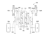
- the gear configuration of the two-motor type vehicle drive device 1 of the embodiment shown in FIG. 1 is as shown in the skeleton diagram shown in FIG.
- the left and right electric motors 2 ⁇ / b> L and 2 ⁇ / b> R are operated by electric power supplied via an inverter 64 from a battery 63 mounted on the vehicle.
- the electric motors 2L and 2R are individually controlled by an electronic control device (not shown), and can generate and output different torques.
- the torque of the motor shaft 5a of the electric motors 2L and 2R is the gear ratio between the input gear shaft 12a of the input gear shafts 12L and 12R of the reduction gears 3L and 3R and the large-diameter input side external gear 13a of the intermediate gear shafts 13L and 13R. And transmitted to the internal gears R L and R R of the gear device 30.
- the output side small gear 13b of the intermediate gear shafts 13L and 13R meshes with the large diameter output gear 14a of the output gear shafts 14L and 14R via the gear device 30, and the number of teeth of the output side small gear 13b and the output gear 14a.
- the torque of the motor shafts 5a of the electric motors 2L and 2R is further increased by the ratio and output to the drive wheels 61L and 61R.
- the gear device 30 is configured by combining two planetary gear mechanisms 30L and 30R having the same three-element and two-degree-of-freedom with coaxial intermediate gear shafts 13L and 13R.
- the planetary gear mechanisms 30L and 30R are of a single pinion type.
- a planetary gear mechanism is used.
- the planetary gear mechanisms 30L and 30R are coaxially provided with sun gears S L and S R and internal gears R L and R R, and between these sun gears S L and S R and the internal gears R L and R R.
- a plurality of planetary gears P L, P R is close to the planetary gear P L, provided the P R rotatably supported by the sun gear S L, S R and the internal gear R L, on R R coaxial It is composed of planetary carriers C L and C R.
- the sun gear S L, S R and the planetary gears P L, P R is the external gear having gear teeth on the outer circumference
- the internal gear R L, R R is the internal gear having gear teeth on the inner peripheral is there.
- the planetary gears P L and P R mesh with the sun gears S L and S R and the internal gears R L and R.
- the gear device 30 includes the first planetary gear mechanism 30L having the sun gear S L , the planet carrier C L , the planet gear P L and the internal gear RL , and the sun gear S R and the planet carrier C.
- a second planetary gear mechanism 30R having a planetary gear P R and the internal gear R R is configured by combining coaxially.
- the torque TM1 generated by the electric motor 2L is transmitted to the intermediate gear shaft 13L by meshing the input gear 12a of the input gear shaft 12L and the input side external gear 13a, and the torque transmitted to the intermediate gear shaft 13L is It is transmitted to the output-side small gear 13b of the intermediate gear shaft 13L via the first planetary gear mechanism 30L, and the output-side small gear 13b of the intermediate gear shaft 13L and the output gear 14a of the output gear shaft 14L are engaged with each other to produce an output gear shaft.
- Drive torque TR is output from 14L to drive wheel 61L.
- the torque TM2 generated by the electric motor 2R is transmitted to the intermediate gear shaft 13R when the input gear 12a of the input gear shaft 12R and the input side external gear 13a are meshed, and the torque transmitted to the intermediate gear shaft 13R is the second torque. It is transmitted to the output-side small gear 13b of the intermediate gear shaft 13R via the planetary gear mechanism 30R, and the output-side small gear 13b of the intermediate gear shaft 13R and the output gear 14a of the output gear shaft 14R are meshed to drive from the output gear shaft 14R.
- a driving torque TR is output to the wheel 61R.
- the outputs from the electric motors 2L and 2R are also given to the internal gears R L and R R of the two planetary gear mechanisms 30L and 30R, respectively, and the outputs from the first coupling member 31 and the second coupling member 32 are drive wheels. It is given to 61L and 61R.
- the 2nd coupling member 32 is comprised by the hollow shaft, the 1st coupling member 31 is penetrated in the inside, and the axis
- the first coupling member 31 has one end a rotation shaft of the (right end in the drawing) is the sun gear S R, the other end (left end in the drawing) are provided through the sun gear S L, connected to the planet carrier C L Has been.
- the second coupling member 32 is a hollow shaft, one end (left end in the drawing) has a rotation shaft of the sun gear S L, the other end (right end in the drawing) is connected to the planet carrier C R.
- the first planetary gear mechanisms 30L and 30R are coupled by the first coupling member 31 and the second coupling member 32.
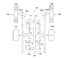
- the gear unit 30 is configured by combining two identical single pinion type planetary gear mechanisms 30L and 30R, it can be represented by two velocity diagrams as shown in FIG.
- the two speed diagrams are shifted up and down, the speed diagram of the left planetary gear mechanism 30L is shown on the upper side, and the speed diagram of the right planetary gear mechanism 30R is shown on the lower side.
- the torques TM1 and TM2 output from the electric motors 2L and 2R are respectively connected to the internal gears via the input side external gears 13a meshing with the input gears 12a of the input gear shafts 12L and 12R.
- the inputs from the electric motors 2L and 2R are the internal gears R L and R R
- the outputs to the drive wheels 61L and 61R are the sun gear S R and the carrier C L
- the sun gear S L and the carrier C R Become.
- the torque difference distributing mechanism is a gear unit 30 two planetary gear mechanism 30L which constitutes the connection of 30R the sun gear S L and the planet carrier C R, the sun gear S R And the planetary carrier C L , a connecting member having a larger diameter than the internal gears R L and R R is not required.
- the torque difference distribution mechanism can be made smaller than those of the prior art 1 and the prior art 2
- the vehicle drive device 1 for an electric vehicle incorporating the torque difference distribution mechanism can be made smaller and lighter.
- the vehicle on which the vehicle drive device 1 is mounted is not limited to an electric vehicle or a hybrid electric vehicle, but may be, for example, a fuel cell vehicle that uses the first electric motor 2L and the second electric motor 2R as driving sources. Good.
- the present invention is not limited to the embodiment described above, and can be implemented in various forms without departing from the gist of the present invention.
Abstract
The present invention addresses the problem of reducing the radial dimension of a gear device 30 mounted in a vehicle drive device 1. In a vehicle drive device, planetary gear mechanisms 30L, 30R which constitute a gear device 30 for distributing, to left and right wheels, power supplied from two electric motors 2L, 2R have: internally toothed gears RL, RR; planetary carriers CL, CR provided coaxially with the internally toothed gears RL, RR; sun gears SL, SR provided coaxially with the internally toothed gears RL, RR; and planetary gears PL, PR as revolving gears. Externally toothed gears 13a as speed reduction mechanisms are connected to the internally toothed gears RL, RR, and the internally toothed gears RL, RR are supported by the planetary carriers CL, CR through bearings 39. The vehicle drive device is characterized in that a hardened raceway surface of the bearing 39 is formed on at least one of the facing surfaces of the internally toothed gear RL, RR and the planetary carrier CL, CR.
Description
この発明は、独立した二つの駆動源からの駆動トルクを左右の駆動輪にトルク差を増幅して伝達することができる車両駆動装置に関するものである。
The present invention relates to a vehicle drive device capable of amplifying a torque difference and transmitting drive torque from two independent drive sources to left and right drive wheels.
電気自動車等の車両において、左右の駆動輪にそれぞれ電動モータを配置して、各電動モータを独立して制御することにより左右輪に適宜駆動トルク差を与えて、これにより車両の旋回モーメントを制御することが知られている。車両のスムーズな旋回走行の実現や、極端なアンダーステア、極端なオーバーステア等の車両の挙動変化を抑制するために、左右の駆動輪の間に大きな駆動トルクの差を発生させることが有効な場合がある。そのため、二つの電動モータから出力されるトルクの差を増幅し、左右の駆動輪に伝達することが望まれる。
In vehicles such as electric cars, electric motors are arranged on the left and right drive wheels, respectively, and each electric motor is controlled independently to give an appropriate drive torque difference between the left and right wheels, thereby controlling the turning moment of the vehicle It is known to do. When it is effective to generate a large difference in driving torque between the left and right drive wheels in order to achieve smooth turning of the vehicle and to suppress changes in vehicle behavior such as extreme understeer and extreme oversteer There is. For this reason, it is desirable to amplify the difference between the torques output from the two electric motors and transmit them to the left and right drive wheels.
特許文献1及び特許文献2には、二つの駆動源と左右の駆動輪との間に、3要素2自由度の遊星歯車構造体を同軸上に二つ組み合わせたトルク差増幅機構である差動装置を備えた車両駆動装置が開示されている。
In Patent Document 1 and Patent Document 2, a differential that is a torque difference amplifying mechanism in which two planetary gear structures with three elements and two degrees of freedom are coaxially arranged between two drive sources and left and right drive wheels. A vehicle drive device comprising the device is disclosed.
特許文献1の図5(a)に開示された車両駆動装置(以下、従来技術1という。)は、図9に示すスケルトン図のような構成になっている。
The vehicle driving device disclosed in FIG. 5A of Patent Document 1 (hereinafter referred to as Conventional Technology 1) has a configuration as shown in the skeleton diagram shown in FIG.
車両駆動装置100は、車両に搭載された左右の電動モータ102L及び電動モータ102Rと、左駆動輪104L及び右駆動輪104Rと、これらの間に設けられる差動装置105と減速ギヤ列106L、106R、107L、107Rとを備えている。
The vehicle drive device 100 includes left and right electric motors 102L and 102R mounted on the vehicle, left drive wheels 104L and right drive wheels 104R, a differential device 105 and reduction gear trains 106L and 106R provided therebetween. , 107L, 107R.
電動モータ102L及び電動モータ102Rは、車両に搭載されたバッテリ(図示省略)からの電力により動作し、電子制御装置(図示省略)により個別に制御され、異なるトルクを発生させて出力することができる。
The electric motor 102L and the electric motor 102R operate with electric power from a battery (not shown) mounted on the vehicle, are individually controlled by an electronic control device (not shown), and can generate and output different torques. .
電動モータ102Lの出力軸102aL、電動モータ102Rの出力軸102aRは、それぞれ減速ギヤ列106L、106Rを介して差動装置105の各結合部材111、112に接続される。差動装置105からの出力は減速ギヤ列107L、107Rを介して左右の駆動輪104L、104Rに与えられる。
The output shaft 102aL of the electric motor 102L and the output shaft 102aR of the electric motor 102R are connected to the coupling members 111 and 112 of the differential device 105 through the reduction gear trains 106L and 106R, respectively. The output from the differential device 105 is given to the left and right drive wheels 104L, 104R via the reduction gear trains 107L, 107R.
差動装置105は、3要素2自由度の同一の遊星歯車機構110L、110Rが同軸上に二つ組み合わされて構成されている。
The differential device 105 is configured by combining two identical planetary gear mechanisms 110L and 110R with three elements and two degrees of freedom on the same axis.
遊星歯車機構110L、110Rには、例えば、シングルピニオン形式の遊星歯車機構が採用されている。シングルピニオン形式の遊星歯車機構は、同軸上に設けられた太陽歯車SL、SR及び内歯車RL、RRと、これら太陽歯車SL、SRと内歯車RL、RRとの間に位置する複数の遊星歯車PL、PRと、遊星歯車PL、PRを回動可能に支持し、太陽歯車SL、SR及び内歯車RL、RRと同軸上に設けられた遊星キャリヤCL、CRとから構成され、遊星歯車PL、PRは太陽歯車SL、SRと内歯車RL、RRとに噛み合っている。ここで、太陽歯車SL、SRと遊星歯車PL、PRは外周にギヤ歯を有する外歯歯車であり、内歯車RL、RRは内周にギヤ歯を有する内歯歯車である。
As the planetary gear mechanisms 110L and 110R, for example, single-pinion type planetary gear mechanisms are employed. The single-pinion type planetary gear mechanism includes a sun gear S L , S R and internal gears R L , R R provided on the same axis, and these sun gears S L , S R and internal gears R L , R R. A plurality of planetary gears P L and P R and planetary gears P L and P R are rotatably supported, and are provided coaxially with the sun gears S L and S R and the internal gears R L and R R. was planet carrier C L, is composed of a C R, the planetary gear P L, P R is engaged the sun gear S L, S R and the internal gear R L, in the R R. Here, the sun gear S L, S R and the planetary gears P L, P R is the external gear having gear teeth on the outer circumference, the internal gear R L, R R is the internal gear having gear teeth on the inner peripheral is there.
この差動装置105は、図9に示すように、太陽歯車SL、遊星キャリヤCL、遊星歯車PL及び内歯車RLを有する第1遊星歯車機構110Lと、同じく太陽歯車SR、遊星キャリヤCR、遊星歯車PR及び内歯車RRを有する第2遊星歯車機構110Rとが同軸上に組み合わされて構成されている。
As shown in FIG. 9, the differential 105 includes a first planetary gear mechanism 110L having a sun gear S L , a planet carrier C L , a planetary gear P L, and an internal gear RL , as well as a sun gear S R , a planetary gear. carrier C R, and a second planetary gear mechanism 110R having a planetary gear P R and the internal gear R R is configured by combining coaxially.
そして、第1遊星歯車機構110Lの太陽歯車SLと第2遊星歯車機構110Rの内歯車RRとが第1結合部材111によって結合され、第1遊星歯車機構110Lの内歯車RLと第2遊星歯車機構110Rの太陽歯車SRとが第2結合部材112によって結合されている。
Then, the sun gear S L of the first planetary gear mechanism 110L and the internal gear R R of the second planetary gear mechanism 110R is coupled by a first coupling member 111, and the internal gear R L of the first planetary gear mechanism 110L second The sun gear S R of the planetary gear mechanism 110R is coupled by the second coupling member 112.
第1結合部材111には、電動モータ102Lで発生されたトルクTM1が減速ギヤ列106Lを介して入力され、第2結合部材112には、電動モータ102Rで発生されたトルクTM2が減速ギヤ列106Rを介して入力される。また、第1遊星歯車機構110Lの遊星キャリヤCL及び第2遊星歯車機構110Rの遊星キャリヤCRは、それぞれ減速ギヤ列107L、107Rを介して左右の駆動輪104L、104Rに接続されて出力が取り出される。
The torque TM1 generated by the electric motor 102L is input to the first coupling member 111 via the reduction gear train 106L, and the torque TM2 generated by the electric motor 102R is input to the second coupling member 112 by the reduction gear train 106R. Is input through. Further, the planet carrier C R of the planetary carrier C L and the second planetary gear mechanism 110R of the first planetary gear mechanism 110L, respectively reduction gear train 107L, through 107R left and right drive wheels 104L, the output is connected to the 104R It is taken out.
次に、特許文献2に開示された車両駆動装置(以下、従来技術2という。)は、図10に示すスケルトン図のような構成になっている。
Next, the vehicle drive device disclosed in Patent Document 2 (hereinafter referred to as Conventional Technology 2) has a configuration as shown in the skeleton diagram shown in FIG.
なお、図10においては、従来技術1との差を分かりやすくするために、左右に電動モータ102L、102Rを配置して従来技術1と同様の図にし、同一構成部分には同一符号を付している。
In FIG. 10, in order to make the difference from the prior art 1 easier to understand, the electric motors 102L and 102R are arranged on the left and right to make the same figure as in the prior art 1, and the same components are denoted by the same reference numerals. ing.
図10に示すように、車両駆動装置100は、車両に搭載された第1の電動モータ102L及び第2の電動モータ102Rと、左駆動輪104L及び右駆動輪104Rと、これらの間に設けられる差動装置105と減速ギヤ列106L、106Rとを備えている。
As shown in FIG. 10, the vehicle drive device 100 is provided between a first electric motor 102L and a second electric motor 102R mounted on the vehicle, a left drive wheel 104L and a right drive wheel 104R, and these. A differential device 105 and reduction gear trains 106L and 106R are provided.
第1の電動モータ102L及び第2の電動モータ102Rは、車両に搭載されたバッテリ(図示省略)からの電力により動作し、電子制御装置(図示省略)により個別に制御され、異なるトルクを発生させて出力することができる。第1の電動モータ102Lの出力軸102aL、第2の電動モータ102Rの出力軸102aRは、それぞれ減速ギヤ列106L、106Rを介して差動装置105の太陽歯車SL、SRに接続される。差動装置105からの出力は左右の駆動輪104L、104Rに与えられる。
The first electric motor 102L and the second electric motor 102R operate with electric power from a battery (not shown) mounted on the vehicle, and are individually controlled by an electronic control device (not shown) to generate different torques. Can be output. The output shaft 102aL of the first electric motor 102L and the output shaft 102aR of the second electric motor 102R are connected to the sun gears S L and S R of the differential device 105 via reduction gear trains 106L and 106R, respectively. The output from the differential device 105 is given to the left and right drive wheels 104L, 104R.
従来技術1と同様に従来技術2の差動装置105は、3要素2自由度の同一の遊星歯車機構110L、110Rが同軸上に二つ組み合わされて構成されている。遊星歯車機構110L、110Rには、例えば、シングルピニオン形式の遊星歯車機構が採用されている。
Like the prior art 1, the differential device 105 of the prior art 2 is configured by combining two identical planetary gear mechanisms 110L and 110R with three elements and two degrees of freedom on the same axis. As the planetary gear mechanisms 110L and 110R, for example, single-pinion type planetary gear mechanisms are employed.
そして、第1の遊星歯車機構110Lの遊星キャリヤCLと第2の遊星歯車機構110Rの内歯車RRとが第1結合部材111によって結合され、第1の遊星歯車機構110Lの内歯車RLと第2の遊星歯車機構110Rの遊星キャリヤCRとが第2結合部材112によって結合されている。
Then, the planet carrier C L of the first planetary gear mechanism 110L and the internal gear R R of the second planetary gear mechanism 110R is coupled by a first coupling member 111, the internal gear R L of the first planetary gear mechanism 110L When the planet carrier C R of the second planetary gear mechanism 110R is coupled by the second coupling member 112.
第1の電動モータ102Lで発生されたトルクTM1が減速ギヤ列106Lを介して第1の遊星歯車機構110Lの太陽歯車SLに入力され、第2の電動モータ102Rで発生されたトルクTM2が減速ギヤ列106Rを介して第2の遊星歯車機構110Rの太陽歯車SRに入力される。
The first electric motor 102L torque TM1 generated in is input to the sun gear S L of the first planetary gear mechanism 110L via a reduction gear train 106L, torque TM2 generated by the second electric motor 102R is decelerated It is input to the sun gear S R of the second planetary gear mechanism 110R through a gear train 106R.
また、第1結合部材111、第2の結合部材112は、それぞれ左右の駆動輪104L、104Rに接続されて出力が取り出される。
Also, the first coupling member 111 and the second coupling member 112 are connected to the left and right drive wheels 104L and 104R, respectively, and outputs are taken out.
この従来技術2では、電動モータ102L、102Rからの入力は、太陽歯車SL、太陽歯車SRとなり、駆動輪104L、104Rへの出力は、キャリヤCLと内歯車RR、キャリヤCRと内歯車RLとなる。
In the prior art 2, the electric motor 102L, input from 102R, the sun gear S L, the sun gear S R, and the drive wheels 104L, output to 104R, the carrier C L and the internal gear R R, and the carrier C R It becomes an internal gear R L.
上記のように、従来技術1及び従来技術2に記載のものにおいては、二つの電動モータ102L、102Rで異なるトルクTM1、TM2を発生させて入力トルク差ΔTINを与えると、差動装置105において入力トルク差ΔTINが増幅され、入力トルク差ΔTINよりも大きな駆動トルク差ΔTOUTを得ることができる。
As described above, in the conventional techniques 1 and 2 described above, when the two electric motors 102 </ b> L and 102 </ b> R generate different torques TM <b> 1 and TM <b> 2 and give the input torque difference ΔTIN, the input is performed in the differential device 105. The torque difference ΔTIN is amplified, and a driving torque difference ΔTOUT larger than the input torque difference ΔTIN can be obtained.
前記従来技術1及び従来技術2では、2つの遊星歯車機構を構成する内歯車RL、RRと結合部材とを接続することによりトルク差を増幅するようにしているため、左右どちらかの内歯車RL、RRと別部材を繋ぐ結合部材の1つが、必ず他方の内歯車RL、RRより大径になるため、装置が大型化するという問題がある。
In the prior art 1 and the prior art 2, since the torque difference is amplified by connecting the internal gears R L and R R constituting the two planetary gear mechanisms and the coupling member, either the right or left inner gear is used. Since one of the coupling members that connect the gears R L and R R to another member always has a larger diameter than the other internal gears R L and R R , there is a problem that the apparatus becomes large.
このため、本願の出願人は、従来技術1と従来技術2におけるトルク差を増幅する歯車装置よりも小型、軽量化を図った車両駆動装置を、既に特許出願を行っている(特願2016-023529号)。
For this reason, the applicant of the present application has already filed a patent application for a vehicle drive device that is smaller and lighter than the gear device that amplifies the torque difference between the prior art 1 and the prior art 2 (Japanese Patent Application No. 2016- No. 023529).
この本願の出願人が特許出願している車両駆動装置(先願例1)は、図11及び図12に示す構成である。
The vehicle drive device (prior application example 1) for which the applicant of this application has applied for a patent has the configuration shown in FIGS.
先願例1の車両駆動装置201における歯車装置300を構成する遊星歯車機構300L、300Rは、それぞれ内歯車RL、RRと、内歯車RL、RRと同軸上に設けられた遊星キャリヤCL、CRと、内歯車RL、RRと同軸上に設けられた太陽歯車SL、SRと、公転歯車としての遊星歯車PL、PRとを有する。歯車装置300は、一方の遊星キャリヤCLと他方の太陽歯車SRとを結合する第1結合部材231と、一方の太陽歯車SLと他方の遊星キャリヤCRとを結合する第2結合部材232を有し、第1結合部材231と第2結合部材232が同軸上に配置されると共に、第1結合部材231および第2結合部材232の内、第2結合部材232が中空軸、第1結合部材231が中空軸に挿通される軸を有し、2つの遊星歯車機構300L、300Rの間を通る軸が二重構造となる構成であって、遊星歯車機構300L、300Rの内歯車RL、RRと減速機構の入力歯車213とを、内歯車RL、RRに設けた外歯車217に係合して連結する構造である。
A planetary gear mechanism 300L constituting the gear device 300 in the vehicle driving apparatus 201 of Sakinegairei 1, 300R, respectively internal gear R L, and R R, the internal gear R L, planet carrier provided on R R coaxial a C L, and C R, the internal gear R L, the sun gear provided on R R coaxial S L, and S R, the planetary gear P L as a revolving wheel, and P R. Gear 300, one of the planet carrier C L and the other of the first coupling member 231 for coupling the sun gear S R, a second coupling member for coupling one of the sun gear S L and the other planet carrier C R 232, the first coupling member 231 and the second coupling member 232 are arranged coaxially, and among the first coupling member 231 and the second coupling member 232, the second coupling member 232 is a hollow shaft, The coupling member 231 has a shaft inserted through the hollow shaft, and the shaft passing between the two planetary gear mechanisms 300L and 300R has a double structure, and the internal gear R L of the planetary gear mechanisms 300L and 300R. , R R and the input gear 213 of the speed reduction mechanism are engaged with and connected to external gears 217 provided on the internal gears R L , R R.
また、特許文献3にも、トルク差増幅機構である差動装置を備えた車両駆動装置(従来技術3)が開示されている。
Also, Patent Document 3 discloses a vehicle drive device (prior art 3) provided with a differential device that is a torque difference amplification mechanism.
従来技術3の車両駆動装置は、図13のスケルトン図に示すように、第1及び第2の駆動源M1、M2と、左右の駆動輪WL、WRと、両駆動源M1、M2と左右の駆動輪WL、WRとの間に介設された差動装置302とを備え、差動装置302は、1本の軸に複数の遊星歯車が連設された連設ピニオン320と、連設ピニオン320の遊星歯車321、322と噛合する太陽歯車324、325、連設ピニオン320を枢支するキャリヤ323、連設ピニオン320の遊星歯車322と噛合する内歯歯車327とをそなえた回転機構である。この差動装置302に対して、駆動源M1、駆動源M2、左右の駆動輪WL、WRが接続され、駆動源M1は中空軸311を介して内歯車327に、駆動源M2は中空軸312を介して第2の太陽歯車325に、左駆動輪WLは軸313Lを介してキャリヤ323に、右駆動輪WRは軸313Rを介して第1の太陽歯車324にそれぞれ接続されている。
As shown in the skeleton diagram of FIG. 13, the vehicle drive device of Prior Art 3 includes first and second drive sources M 1 and M 2, left and right drive wheels WL and WR, both drive sources M 1 and M 2, A differential device 302 interposed between the drive wheels WL and WR. The differential device 302 includes a continuous pinion 320 having a plurality of planetary gears connected to one shaft, and a continuous pinion. The rotating mechanism includes sun gears 324 and 325 that mesh with the planetary gears 321 and 322 of 320, a carrier 323 that pivotally supports the continuous pinion 320, and an internal gear 327 that meshes with the planetary gear 322 of the continuous pinion 320. . A drive source M1, a drive source M2, and left and right drive wheels WL, WR are connected to the differential device 302. The drive source M1 is connected to the internal gear 327 via the hollow shaft 311, and the drive source M2 is connected to the hollow shaft 312. Are connected to the second sun gear 325, the left driving wheel WL is connected to the carrier 323 via the shaft 313L, and the right driving wheel WR is connected to the first sun gear 324 via the shaft 313R.
ところで、前記トルク差増幅機構である差動装置には、いずれも遊星歯車機構が同軸上に二つ組み合わされている。
By the way, in each of the differential gears that are the torque difference amplification mechanism, two planetary gear mechanisms are coaxially combined.
2つの遊星歯車機構の回転要素である内歯車RL、RRと遊星キャリヤCL、CRとの間には、回転を支持する軸受が必要である。
Between the internal gears R L , R R and the planet carriers C L , C R which are the rotating elements of the two planetary gear mechanisms, a bearing for supporting the rotation is required.
従来技術1~3では、回転を支持する軸受の具体例は示されていないが、先願例1では、図11及び図12に示すように、この軸受として、深溝玉軸受を使用している。
In the prior arts 1 to 3, no specific example of a bearing that supports rotation is shown, but in the prior application example 1, as shown in FIGS. 11 and 12, a deep groove ball bearing is used as this bearing. .
すなわち、内歯車RL、RRと遊星キャリヤCL、CRとの間に、深溝玉軸受220を配置している。
That is, the deep groove ball bearing 220 is disposed between the internal gears R L and R R and the planetary carriers C L and C R.
深溝玉軸受220は、内輪220a、転動体220b、外輪220cからなり、内輪220a、転動体220b、外輪220cという軸受要素を内歯車RL、RRと遊星キャリヤCL、CRとの間に配置する必要があるため、内輪220aや外輪220cの厚み分だけ、径方向の寸法が大型化する。
The deep groove ball bearing 220 includes an inner ring 220a, a rolling element 220b, and an outer ring 220c. The bearing elements such as the inner ring 220a, the rolling element 220b, and the outer ring 220c are arranged between the inner gears R L and R R and the planetary carriers C L and C R. Since it is necessary to arrange them, the radial dimension increases by the thickness of the inner ring 220a and the outer ring 220c.
車両駆動装置は、車体に搭載されるため、搭載空間を小さくして車室空間を広く確保することが優位であり、トルク差を増幅する歯車装置の小型化、軽量化は必須である。
Since the vehicle drive device is mounted on the vehicle body, it is advantageous to reduce the mounting space and secure a wide cabin space, and it is essential to reduce the size and weight of the gear device that amplifies the torque difference.
そこで、この発明は、車両駆動装置に組み込むトルク差増幅機構の径方向寸法の小型化を図ることを課題とするものである。
Therefore, an object of the present invention is to reduce the size in the radial direction of a torque difference amplification mechanism incorporated in a vehicle drive device.
前記の課題を解決するために、この発明は、車両に搭載され独立して制御可能な二つの駆動源と左右の駆動輪との間に、3要素2自由度の遊星歯車機構を同軸上に二つ組み合わせ、一方の遊星歯車機構の特定の要素と、他方の遊星歯車機構の特定の要素とを、第1結合部材と第2結合部材により相互に連結して二つの駆動源から左右の駆動輪にトルク差を増幅して出力する差動装置を設け、前記遊星歯車機構は、内歯車と、前記内歯車と同軸上に設けられた遊星キャリヤと、前記内歯車と同軸上に設けられた太陽歯車と、公転歯車としての遊星歯車とを有し、前記内歯車に減速機構としての外歯車が連結され、前記内歯車が前記遊星キャリヤに対して軸受を介して支持されている車両駆動装置において、前記内歯車と遊星キャリヤの対向面の少なくとも一方の面に、焼入れされた前記軸受の軌道面を形成したことを特徴とする。
In order to solve the above-described problems, the present invention provides a three-element and two-degree-of-freedom planetary gear mechanism coaxially between two drive sources mounted on a vehicle and independently controllable and left and right drive wheels. Two combinations, a specific element of one planetary gear mechanism and a specific element of the other planetary gear mechanism are connected to each other by a first coupling member and a second coupling member to drive left and right from two driving sources. A differential device for amplifying and outputting a torque difference is provided on the ring, and the planetary gear mechanism is provided with an internal gear, a planet carrier provided coaxially with the internal gear, and provided coaxially with the internal gear. A vehicle drive device having a sun gear and a planetary gear as a revolving gear, an external gear as a speed reduction mechanism connected to the internal gear, and the internal gear supported by the planet carrier via a bearing The opposing surface of the internal gear and the planet carrier On at least one side, characterized in that the formation of the raceway surface of the bearing that is hardened.
前記内歯車の内径面に、焼入れされた前記軸受の軌道面を形成してもよいし、前記遊星キャリヤの外径面に、焼入れされた前記軸受の軌道面を形成してもよい。
The bearing surface of the hardened bearing may be formed on the inner diameter surface of the internal gear, or the raceway surface of the hardened bearing may be formed on the outer diameter surface of the planet carrier.
前記内歯車または遊星キャリヤの材質を肌焼鋼とし、浸炭焼入れにより前記軸受の軌道面を形成することができる。
The material of the internal gear or planetary carrier is case-hardened steel, and the raceway surface of the bearing can be formed by carburizing and quenching.
また、前記内歯車または遊星キャリヤの材質を中炭素鋼とし、高周波焼入れにより前記軸受の軌道面を形成するようにしてもよい。
Further, the material of the internal gear or planet carrier may be medium carbon steel, and the raceway surface of the bearing may be formed by induction hardening.
前記内歯車の歯部も高周波焼入れするようにしてもよい。
The teeth of the internal gear may also be induction hardened.
前記軸受を深溝玉軸受とし、深溝玉軸受の保持器を樹脂製の冠型にすることができる。
The bearing can be a deep groove ball bearing, and the cage of the deep groove ball bearing can be a resin crown.
前記軸受として、保持器付きの円筒ころ軸受を使用し、前記軌道面の外側端部近傍に、スラストワッシャを配置してもよい。
A cylindrical roller bearing with a cage may be used as the bearing, and a thrust washer may be disposed near the outer end of the raceway surface.
前記軸受として、すべり軸受を使用し、軌道面にすべり軸受を配置する段差部を設けてもよい。
As the bearing, a slide bearing may be used, and a stepped portion for arranging the slide bearing on the raceway surface may be provided.
以上のように、この発明によれば、内歯車と遊星キャリヤの対向面の少なくとも一方の面に、焼入れされた前記軸受の軌道面を直接形成することにより、外輪又は内輪の少なくともいずれか一方を省略できるので、内輪又は外輪の厚み分だけ径方向寸法を小さくすることができる。
As described above, according to the present invention, at least one of the outer ring and the inner ring is formed by directly forming the hardened raceway surface of the bearing on at least one of the opposing surfaces of the inner gear and the planetary carrier. Since it can be omitted, the radial dimension can be reduced by the thickness of the inner ring or the outer ring.
以下、この発明の実施の形態を添付図面に基づいて説明する。
Hereinafter, embodiments of the present invention will be described with reference to the accompanying drawings.
図7に示す電気自動車AMは、後輪駆動方式であり、シャーシ60と、後輪としての駆動輪61L、61Rと、前輪62L、62Rと、この発明に係る2モータ式の車両駆動装置1、バッテリ63、インバータ64等を備える。図7では、車両駆動装置1の歯車構成をスケルトン図で示している。
The electric vehicle AM shown in FIG. 7 is a rear wheel drive system, and includes a chassis 60, drive wheels 61L and 61R as rear wheels, front wheels 62L and 62R, and a two-motor vehicle drive device 1 according to the present invention. A battery 63, an inverter 64, and the like are provided. In FIG. 7, the gear structure of the vehicle drive device 1 is shown with the skeleton figure.
図1に示す車両駆動装置1は、車両に搭載され独立して制御可能な二つの駆動源としての電動モータ2L、2Rと、左右の駆動輪61L、61Rと二つの電動モータ2L、2Rとの間に設けられる左右2基の減速装置3L、3Rとを備える。
A vehicle drive device 1 shown in FIG. 1 includes two electric motors 2L and 2R that are mounted on a vehicle and can be controlled independently, and left and right drive wheels 61L and 61R and two electric motors 2L and 2R. 2 left and right reduction gears 3L and 3R provided between them.
2モータ式の車両駆動装置1の駆動トルクは、等速ジョイント65a、65bと中間シャフト65cからなるドライブシャフトを介して左右の駆動輪61L、61Rに伝達される。
The driving torque of the two-motor type vehicle drive device 1 is transmitted to the left and right drive wheels 61L and 61R via a drive shaft composed of constant velocity joints 65a and 65b and an intermediate shaft 65c.
なお、2モータ式の車両駆動装置1の搭載形態としては、図7に示す後輪駆動方式の他、前輪駆動方式、四輪駆動方式でもよい。四輪駆動方式においては、図1に示す車両駆動装置は前輪又は後輪の双方に搭載してもよく、又はそのいずれか一方に搭載して、もう一方は例えばエンジン駆動の歯車装置など他の駆動装置であってもよい。
In addition, as a mounting form of the two-motor type vehicle drive device 1, a front wheel drive system or a four wheel drive system may be used in addition to the rear wheel drive system shown in FIG. In the four-wheel drive system, the vehicle drive device shown in FIG. 1 may be mounted on both the front wheels or the rear wheels, or may be mounted on one of them, and the other may be another device such as an engine-driven gear device. It may be a drive device.
2モータ式の車両駆動装置1における左右の電動モータ2L、2Rは、同一の最大出力を有する同一の出力特性の電動モータが用いられ、図1に示すように、モータハウジング4L、4R内に収容されている。
The left and right electric motors 2L and 2R in the two-motor type vehicle drive device 1 use electric motors having the same maximum output and the same output characteristics, and are housed in motor housings 4L and 4R as shown in FIG. Has been.
モータハウジング4L、4Rは、円筒形のモータハウジング本体4aL、4aRと、このモータハウジング本体4aL、4aRの外側面を閉塞する外側壁4bL、4bRと、モータハウジング本体4aL、4aRの内側面に減速装置3L、3Rと隔てる内側壁4cL、4cRとからなる。内側壁4cL、4cRには、モータ軸5aを引き出す開口部が設けられている。
The motor housings 4L and 4R include cylindrical motor housing bodies 4aL and 4aR, outer walls 4bL and 4bR that close the outer surfaces of the motor housing bodies 4aL and 4aR, and reduction gears on the inner surfaces of the motor housing bodies 4aL and 4aR. It consists of inner walls 4cL and 4cR separated from 3L and 3R. The inner walls 4cL and 4cR are provided with openings through which the motor shaft 5a is drawn.
電動モータ2L、2Rは、図1に示すように、モータハウジング本体4aL、4aRの内周面にステータ6を設け、このステータ6の内周にすきまをおいてロータ5を設けたラジアルギャップタイプのものを使用している。なお、電動モータ2L、2Rは、アキシャルギャップタイプのものを使用してもよい。
As shown in FIG. 1, the electric motors 2 </ b> L and 2 </ b> R are of a radial gap type in which a stator 6 is provided on the inner peripheral surface of the motor housing main body 4 aL and 4 aR, and a rotor 5 is provided with a gap in the inner periphery of the stator 6. I am using something. The electric motors 2L and 2R may be axial gap types.
ロータ5は、モータ軸5aを中心部に有し、そのモータ軸5aはモータハウジング本体4aL、4aRの内側壁4cL、4cRの開口部からそれぞれ減速装置3L、3R側に引き出されている。モータハウジング本体4aL、4aRの内側壁4cL、4cRの開口部周りとモータ軸5aとの間にはシール部材7が設けられている。
The rotor 5 has a motor shaft 5a in the center, and the motor shaft 5a is drawn from the openings of the inner walls 4cL and 4cR of the motor housing main bodies 4aL and 4aR to the reduction gears 3L and 3R, respectively. A seal member 7 is provided between the periphery of the inner side walls 4cL and 4cR of the motor housing bodies 4aL and 4aR and the motor shaft 5a.
モータ軸5aは、モータハウジング本体4aL、4aRの内側壁4cL、4cRと外側壁4bL、4bRとに転がり軸受8a、8bによって回転自在に支持されている(図1参照)。図1では、軸受8a、8bは同一のものとしているが、異なるサイズのものを組み合わせてもよい。
The motor shaft 5a is rotatably supported by the rolling bearings 8a and 8b on the inner walls 4cL and 4cR and the outer walls 4bL and 4bR of the motor housing bodies 4aL and 4aR (see FIG. 1). In FIG. 1, the bearings 8a and 8b are the same, but different sizes may be combined.
左右並列に設けられた2基の減速装置3L、3Rを収容する減速装置ハウジング9は、減速装置3L、3Rの歯車軸と直交する方向に3ピースに分割され、図1に示すように、中央ハウジング9aとこの中央ハウジング9aの両側面に固定される左右の側面ハウジング9bL、9bRの3ピース構造になっている。左右の側面ハウジング9bL、9bRは、中央ハウジング9aの両側の開口部に複数のボルト(図示省略)によって固定されている。
A reduction gear housing 9 that accommodates two reduction gears 3L and 3R provided in parallel on the left and right is divided into three pieces in a direction perpendicular to the gear shafts of the reduction gears 3L and 3R, as shown in FIG. The housing 9a has a three-piece structure including left and right side housings 9bL and 9bR fixed to both side surfaces of the central housing 9a. The left and right side housings 9bL and 9bR are fixed to the openings on both sides of the central housing 9a by a plurality of bolts (not shown).
減速装置ハウジング9の側面ハウジング9bL、9bRのアウトボード側(車体外側)の側面と電動モータ2L、2Rのモータハウジング本体4aL、4aRの内側壁4cL、4cRとを、複数のボルト10によって固定することにより、減速装置ハウジング9の左右に2基の電動モータ2L、2Rが固定配置される(図1参照)。
A plurality of bolts 10 are used to fix side faces 9bL and 9bR of the reduction gear housing 9 on the side of the outboard side (outside the vehicle body) and the inner side walls 4cL and 4cR of the motor housing bodies 4aL and 4aR of the electric motors 2L and 2R. Thus, the two electric motors 2L and 2R are fixedly arranged on the left and right sides of the reduction gear housing 9 (see FIG. 1).
中央ハウジング9aには、図1に示すように、中央に仕切り壁11が設けられている。減速装置ハウジング9は、この仕切り壁11によって左右に2分割され、2基の減速装置3L、3Rを収容する独立した左右の収容室が並列に設けられている。
As shown in FIG. 1, the central housing 9a is provided with a partition wall 11 in the center. The speed reducer housing 9 is divided into left and right parts by the partition wall 11, and independent left and right accommodation chambers for accommodating the two speed reducers 3L and 3R are provided in parallel.
減速装置3L、3Rは、図1に示すように、左右対称形に設けられ、モータ軸5aから動力が伝達される入力歯車12aを有する入力歯車軸12L、12Rと、この入力歯車12aに噛み合う大径の入力側外歯車13a及び出力歯車14aに噛み合う出力側小径歯車13bの双方を有する中間歯車軸13L、13Rと、出力歯車14aを有し、減速装置ハウジング9から引き出されて等速ジョイント65a、65b、中間シャフト65c(図7参照)を介して駆動輪61L、61R(図7参照)にトルクを伝達する出力歯車軸14L、14Rとを備える平行軸歯車減速機である。左右2基の減速装置3L、3Rの各入力歯車軸12L、12R、各中間歯車軸13L、13R、各出力歯車軸14L、14Rは、それぞれが同軸上に配置されている。
As shown in FIG. 1, the reduction gears 3L and 3R are provided symmetrically and have large input gear shafts 12L and 12R having an input gear 12a to which power is transmitted from the motor shaft 5a, and the input gear 12a. Intermediate gear shafts 13L and 13R having both an output side small gear 13b meshing with an input side external gear 13a and an output gear 14a, and an output gear 14a. The constant velocity joint 65a is pulled out from the speed reducer housing 9. 65 is a parallel shaft gear reducer including output gear shafts 14L and 14R that transmit torque to drive wheels 61L and 61R (see FIG. 7) via an intermediate shaft 65c (see FIG. 7). The input gear shafts 12L and 12R, the intermediate gear shafts 13L and 13R, and the output gear shafts 14L and 14R of the left and right reduction gears 3L and 3R are coaxially arranged.
減速装置3L、3Rの入力歯車軸12L、12Rの両端は、中央ハウジング9aの仕切り壁11の左右両面に形成した軸受嵌合穴16aと側面ハウジング9bL、9bRに形成した軸受嵌合穴16bにそれぞれ転がり軸受17a、17bを介して回転自在に支持されている。軸受嵌合穴16a、16bは、転がり軸受17a、17bの外輪が当接する壁部のある段付き形状になっている。図1では転がり軸受17a、17bは同一のものとしているが、異なるサイズのもので組みあわせてもよい。
Both ends of the input gear shafts 12L and 12R of the reduction gears 3L and 3R are respectively connected to bearing fitting holes 16a formed on both left and right sides of the partition wall 11 of the central housing 9a and bearing fitting holes 16b formed on the side housings 9bL and 9bR. It is rotatably supported via rolling bearings 17a and 17b. The bearing fitting holes 16a and 16b have a stepped shape having a wall portion with which the outer rings of the rolling bearings 17a and 17b abut. In FIG. 1, the rolling bearings 17a and 17b are the same, but they may be combined in different sizes.
入力歯車軸12L、12Rのアウトボード側の端部は、側面ハウジング9bL、9bRに設けた開口部から外側に引き出されており、開口部と入力歯車軸12L、12Rの外側端部との間にはオイルシール18を設け、減速装置ハウジング9に封入された潤滑油の漏洩を防止している。
The end portions on the outboard side of the input gear shafts 12L, 12R are drawn outward from the openings provided in the side housings 9bL, 9bR, and between the openings and the outer ends of the input gear shafts 12L, 12R. Is provided with an oil seal 18 to prevent leakage of the lubricating oil sealed in the speed reducer housing 9.
入力歯車軸12L、12Rは中空構造であり、この中空の入力歯車軸12L、12Rに、モータ軸5aの端部が挿入されている。入力歯車軸12L、12Rとモータ軸5aとは、スプライン(セレーションも含む、以下同じ)結合されている。
The input gear shafts 12L and 12R have a hollow structure, and end portions of the motor shaft 5a are inserted into the hollow input gear shafts 12L and 12R. The input gear shafts 12L, 12R and the motor shaft 5a are coupled by splines (including serrations, the same applies hereinafter).
中間歯車軸13L、13Rは、少なくとも一つ以上配置されており、図1に示す実施形態では、一対の中間歯車軸13L、13Rを有する。
At least one or more intermediate gear shafts 13L and 13R are arranged. In the embodiment shown in FIG. 1, the intermediate gear shafts 13L and 13R have a pair of intermediate gear shafts 13L and 13R.
中間歯車軸13L、13Rは、その外周面に入力歯車12aに噛み合う入力側外歯車13aを有し、また出力歯車14aに噛み合う出力側小径歯車13bを有する段付きの歯車軸を構成している。この中間歯車軸13L、13Rの両端は、中央ハウジング9aの仕切り壁11の両面に形成した軸受嵌合穴19aと側面ハウジング9bL、9bRに形成した軸受嵌合穴19bとに転がり軸受20a、20bを介して支持されている。そして、軸受嵌合穴19a、19bは、転がり軸受20a、20bの外輪が当接する壁部のある段付き形状になっており、軸受嵌合穴19aは後述する第1結合部材31と第2結合部材32が通るように貫通している。図1では、転がり軸受20a、20bは異なるサイズのものとしているが、同一のもので組み合せてもよい。
The intermediate gear shafts 13L and 13R constitute a stepped gear shaft having an input side external gear 13a meshing with the input gear 12a on the outer peripheral surface and an output side small gear 13b meshing with the output gear 14a. At both ends of the intermediate gear shafts 13L and 13R, rolling bearings 20a and 20b are fitted into bearing fitting holes 19a formed on both surfaces of the partition wall 11 of the central housing 9a and bearing fitting holes 19b formed on the side housings 9bL and 9bR. Is supported through. The bearing fitting holes 19a and 19b have a stepped shape with a wall portion with which the outer rings of the rolling bearings 20a and 20b come into contact. The bearing fitting hole 19a has a first coupling member 31 and a second coupling which will be described later. It penetrates so that member 32 may pass. In FIG. 1, the rolling bearings 20a and 20b have different sizes, but they may be combined with each other.
同軸上に配置された中間歯車軸13L、13Rには、この中間歯車軸13L、13Rと同軸上に、二つの電動モータ2L、2Rから与えられる駆動トルクを左右の駆動輪61L、61Rにトルク差を増幅して分配する歯車装置30が組み込まれている。
The intermediate gear shafts 13L and 13R arranged on the same axis are connected to the intermediate gear shafts 13L and 13R so that the drive torque applied from the two electric motors 2L and 2R is a torque difference between the left and right drive wheels 61L and 61R. A gear device 30 for amplifying and distributing the signal is incorporated.
歯車装置30は、同軸に配された左右の1対の中間歯車軸13L、13Rと同軸上に組み合わせた、3要素2自由度の二つの遊星歯車機構30L、30Rからなる。
The gear device 30 is composed of two planetary gear mechanisms 30L and 30R with three elements and two degrees of freedom, which are coaxially combined with a pair of left and right intermediate gear shafts 13L and 13R arranged coaxially.
歯車装置30を構成する遊星歯車機構30L、30Rは、中間歯車軸13L、13Rの大径の入力側外歯車13aにそれぞれ組み込まれた内歯車RL、RRと、内歯車RL、RRと同軸上に設けられた太陽歯車SL、SRと、内歯車RL、RRと太陽歯車SL、SRに噛み合う公転歯車として周方向に等分配置された複数の遊星歯車PL、PRと、遊星歯車PL、PRを回動可能に支持し、内歯車RL、RRと同軸上に設けられた遊星キャリヤCL、CRと、一方の遊星キャリヤCL(図1では図の左側)と他方の太陽歯車SR(図1では図の右側)とを結合する第1結合部材31と、一方の太陽歯車SL(図1では図の左側)と他方の遊星キャリヤCR(図1では図の右側)とを結合する第2結合部材32と、内歯車RL、RRに連結された、入力歯車軸12L、12Rの入力歯車12aと噛み合う中間歯車軸13L、13Rの入力側外歯車13aと、出力歯車軸14L、14Rの出力歯車14aと噛み合う中間歯車軸13L、13Rの出力側小径歯車13bとを有し、中間歯車軸13L、13Rの出力側小径歯車13bを、遊星キャリヤCL、CRに連結した構成である。
The planetary gear mechanisms 30L and 30R constituting the gear device 30 include internal gears R L and R R and internal gears R L and R R incorporated in the large-diameter input side external gear 13a of the intermediate gear shafts 13L and 13R, respectively. A plurality of planetary gears P L arranged equally in the circumferential direction as revolving gears meshed with the sun gears S L , S R and the internal gears R L , R R and the sun gears S L , S R provided coaxially with each other. , P R and the planetary gears P L, the P R rotatably supported internal gear R L, planetary provided on R R coaxial carrier C L, C R and, one of the planet carrier C L ( In FIG. 1, a first coupling member 31 that couples the other sun gear S R (the right side of the figure in FIG. 1) with one sun gear S L (the left side of the figure in FIG. 1) and the other sun gear S R a planet carrier C R second coupling member 32 for coupling the (right side in FIG. in FIG. 1), the internal gear R L, linked to R R, oN An input side external gear 13a of the intermediate gear shafts 13L and 13R meshing with the input gear 12a of the gear shafts 12L and 12R, and an output side small gear 13b of the intermediate gear shafts 13L and 13R meshing with the output gear 14a of the output gear shafts 14L and 14R The output side small-diameter gear 13b of the intermediate gear shafts 13L and 13R is connected to the planetary carriers C L and C R.
なお、中間歯車軸13L、13Rを複数対設けた場合には、歯車装置30を構成する遊星歯車機構30L、30Rは、いずれか一対の中間歯車軸13L、13Rのみに組み込まれる。内歯車RL、RRに連結された入力側外歯車13aは、複数対の中間歯車軸13L、13Rのうち、駆動側の中間歯車軸13L、13Rに設けられた出力側小径歯車13b、または入力歯車軸12L、12Rの入力歯車12aと噛み合うように配置され、また、遊星歯車機構30L、30Rと同軸上に設けられた出力側小径歯車13bが、複数対の中間歯車軸13L、13Rのうちの従動側の中間歯車軸13L、13Rに設けられた入力側外歯車13a、または出力歯車軸14L、14Rの出力歯車14aと噛み合うように配置される。
When a plurality of pairs of intermediate gear shafts 13L and 13R are provided, the planetary gear mechanisms 30L and 30R constituting the gear device 30 are incorporated only in any one of the pair of intermediate gear shafts 13L and 13R. The input-side external gear 13a connected to the internal gears R L , R R is an output-side small gear 13b provided on the drive-side intermediate gear shafts 13L, 13R among the plural pairs of intermediate gear shafts 13L, 13R, or An output-side small-diameter gear 13b that is arranged so as to mesh with the input gear 12a of the input gear shafts 12L and 12R and is coaxial with the planetary gear mechanisms 30L and 30R is formed of a plurality of pairs of intermediate gear shafts 13L and 13R. Are arranged so as to mesh with the input side external gear 13a provided on the driven intermediate gear shafts 13L, 13R or the output gear 14a of the output gear shafts 14L, 14R.
遊星キャリヤCL、CRは、図2に示すように、遊星歯車PL、PRを支持するキャリヤピン33と、キャリヤピン33のアウトボード側端部に連結されたアウトボード側のキャリヤフランジ34aと、インボード側端部に連結されたインボード側のキャリヤフランジ34bを有する。
As shown in FIG. 2, the planetary carriers C L and C R are composed of a carrier pin 33 that supports the planetary gears P L and P R , and an outboard side carrier flange that is connected to the outboard side end of the carrier pin 33. 34a and an inboard carrier flange 34b connected to the inboard side end.
アウトボード側のキャリヤフランジ34aは、アウトボード側に延びる中空軸部35を備えており、中空軸部35のアウトボード側の端部が、減速装置ハウジング9の側面ハウジング9bL、9bRに形成した軸受嵌合穴19bに転がり軸受20bを介して支持されている(図1参照)。
The carrier flange 34a on the outboard side includes a hollow shaft portion 35 extending toward the outboard side, and the end portion on the outboard side of the hollow shaft portion 35 is formed on the side housings 9bL and 9bR of the speed reducer housing 9. It is supported by the fitting hole 19b via the rolling bearing 20b (refer FIG. 1).
インボード側のキャリヤフランジ34bは、インボード側に延びる中空軸部36を備えており、中空軸部36のインボード側の端部が、中央ハウジング9aの仕切り壁11に形成した軸受嵌合穴19aに転がり軸受20aを介して支持されている(図1参照)。
The carrier flange 34b on the inboard side includes a hollow shaft portion 36 extending toward the inboard side, and an end portion on the inboard side of the hollow shaft portion 36 is formed in a bearing fitting hole formed in the partition wall 11 of the central housing 9a. It is supported by 19a via the rolling bearing 20a (refer FIG. 1).
図1及び図2に示す実施形態では、前記出力側小径歯車13bが、キャリヤフランジ34aの中空軸部35の外周面に一体に形成されている。
In the embodiment shown in FIGS. 1 and 2, the output-side small-diameter gear 13b is integrally formed on the outer peripheral surface of the hollow shaft portion 35 of the carrier flange 34a.
遊星歯車PL、PRは、針状ころ軸受37を介してキャリヤピン33によって支持されている。
The planetary gears P L and P R are supported by the carrier pin 33 via the needle roller bearing 37.
ここで、前記各キャリヤフランジ34a、34bの対向面と遊星歯車PL、PRの間にスラスト板(図示省略)を挿入し、遊星歯車PL、PRの回転の円滑化を図ってもよい。
Here, each of the carrier flanges 34a, 34b facing surface and a planetary gear P L of, inserting the thrust plate (not shown) between the P R, the planetary gear P L, even working to smooth rotation of the P R Good.
前記各キャリヤフランジ34a、34bの外周面と内歯車RL、RRとの間には、軸受39を配置している。
A bearing 39 is disposed between the outer peripheral surfaces of the carrier flanges 34a and 34b and the internal gears R L and R R.
この内歯車RL、RRをキャリヤフランジ34a、34bに支持する軸受39は、図1及び図2に示す実施形態では、深溝玉軸受を採用している。そして、深溝玉軸受は、外輪39aと、内輪39bと、転動体39cとからなるが、図1及び図2に示す実施形態では、外輪39aの軌道面を内歯車RL、RRの内径面に直接形成している。
In the embodiment shown in FIGS. 1 and 2, a deep groove ball bearing is adopted as the bearing 39 for supporting the internal gears R L and R R on the carrier flanges 34a and 34b. The deep groove ball bearing includes an outer ring 39a, an inner ring 39b, and a rolling element 39c. In the embodiment shown in FIGS. 1 and 2, the raceway surface of the outer ring 39a is used as the inner diameter surface of the internal gears R L and R R. Formed directly.
外輪39aの軌道面を内歯車RL、RRの内径面に直接形成することにより、別部品の外輪を内歯車RL、RRの内径面に組み込んだ場合よりも、外輪の厚み分だけ径方向寸法を小さくすることができる。
By forming the raceway surface of the outer ring 39a directly on the inner diameter surface of the inner gears R L and R R , the outer ring 39a has a thickness corresponding to the thickness of the outer ring than when the outer ring of a separate part is incorporated in the inner diameter surface of the inner gears R L and R R The radial dimension can be reduced.
内歯車RL、RR等の歯車は、一般にその歯の歯面強度や歯元強度を十分に確保するために、肌焼鋼へ表面硬化焼入れを施されたものが使われる。一方、歯車の回転を支持する軸受も、荷重によって転動体及び軌道面に生じる高面圧に耐える必要があり、例えば、高炭素クロム合金鋼へ無心焼入れを施したものや、肌焼鋼へ表面硬化焼入れを施したものが使われる。つまり歯車・軸受のいずれも焼入れによる十分な硬さ(例えば、表面硬さ58HRC以上)を必要とする。
As the gears such as the internal gears R L and R R , in general, a case-hardened steel that has been subjected to surface hardening and quenching is used in order to sufficiently secure the tooth surface strength and tooth root strength of the teeth. On the other hand, bearings that support the rotation of gears also need to withstand high surface pressure generated on the rolling elements and raceways by the load.For example, high-carbon chromium alloy steel that has been subjected to core quenching or surface-hardened steel Hardened and hardened. That is, both the gear and the bearing need to have sufficient hardness (for example, a surface hardness of 58 HRC or more) by quenching.
図1及び図2の実施形態では、内歯車RL、RRは、例えば、肌焼鋼であり、また、熱処理として浸炭焼入れが施されており、歯部及び軸受軌道面の表面硬さは58HRC以上に確保されている。
In the embodiment of FIGS. 1 and 2, the internal gears R L and R R are, for example, case-hardened steel, and carburized and quenched as a heat treatment, and the surface hardness of the tooth portion and the bearing raceway surface is It is secured at 58HRC or higher.
また、図3に示す実施形態は、内歯車RL、RRをキャリヤフランジ34a、34bに支持する軸受39として、図1及び図2に示す実施形態と同様に、深溝玉軸受を採用するが、図3に示す実施形態では、軸受の内輪39bに相当する軌道面を、キャリヤフランジ34a、34bの外径面に直接形成している。
In the embodiment shown in FIG. 3, a deep groove ball bearing is adopted as the bearing 39 for supporting the internal gears R L and R R on the carrier flanges 34a and 34b, as in the embodiment shown in FIGS. In the embodiment shown in FIG. 3, the raceway surface corresponding to the inner ring 39b of the bearing is formed directly on the outer diameter surfaces of the carrier flanges 34a and 34b.
キャリヤフランジ34a、34bを備える遊星キャリヤCL、CRは、例えば中炭素鋼であり、また、その軸受軌道面には熱処理として高周波焼入れが施され、その表面硬さは58HRC以上に確保されている。遊星キャリヤCL、CRに形成した出力側小径歯車13bの歯もまた同様に熱処理されている。高周波焼入れされる箇所については、図3中に太い一点鎖線で示す。
The planetary carriers C L and C R provided with the carrier flanges 34a and 34b are, for example, medium carbon steel, and the bearing raceway surface is subjected to induction hardening as a heat treatment, and the surface hardness is secured to 58 HRC or more. Yes. The teeth of the output-side small-diameter gear 13b formed on the planetary carriers C L and C R are also heat-treated in the same manner. A portion to be induction-hardened is indicated by a thick dashed line in FIG.
図1乃至図3では転がり軸受39はアウトボード側とインボード側で同一であったが、異なる形態の組み合わせでもよい。即ち、アウトボード側の軸受は図1及び図2のように外輪39aの軌道面を内歯車RL、RRの内径面に直接形成し、インボード側の軸受は図3のように内輪39aの軌道面をキャリヤフランジ34a、34bの外径面に直接形成してもよい。同様に、即ち、インボード側の軸受は外輪39aの軌道面を内歯車RL、RRの内径面に直接形成し、アウトボード側の軸受は内輪39aの軌道面をキャリヤフランジ34a、34bの外径面に直接形成してもよい。アウトボード側の軸受とインボード側の軸受とで軸受のサイズが異なってもよい。
In FIGS. 1 to 3, the rolling bearing 39 is the same on the outboard side and the inboard side, but a combination of different forms may be used. That is, the bearing on the outboard side directly forms the raceway surface of the outer ring 39a on the inner diameter surface of the internal gears R L and R R as shown in FIGS. 1 and 2, and the bearing on the inboard side is the inner ring 39a as shown in FIG. The raceway surface may be formed directly on the outer diameter surface of the carrier flanges 34a, 34b. Similarly, the bearing on the inboard side directly forms the raceway surface of the outer ring 39a on the inner diameter surface of the internal gears R L and R R , and the bearing on the outboard side forms the raceway surface of the inner ring 39a on the carrier flanges 34a and 34b. You may form directly on an outer diameter surface. The size of the bearing may be different between the bearing on the outboard side and the bearing on the inboard side.
次に、図4に示す実施形態は、内歯車RL、RRをキャリヤフランジ34a、34bに支持する軸受39として、保持器付き円筒ころ軸受を採用している。
Next, the embodiment shown in FIG. 4 employs a cylindrical roller bearing with a cage as the bearing 39 for supporting the internal gears R L and R R on the carrier flanges 34a and 34b.
図4に示す実施形態では、外輪39aの軌道面は、内歯車RL、RRの内径面に直接形成され、さらに、内輪39bの軌道面も、キャリヤフランジ34a、34bの外周面に直接形成されている。外輪39aの軌道面の内側端には段差が設けられており、転動体39cが移動するのを規制している。また、内輪39bの軌道面の外側近傍にはスラストリング39dが設けられている。このスラストリング39dは、その更に外側に設けた止め輪39eによって脱落しないように規制されている。これらにより、転動体39cは段差とスラストリング39dとによってその軸方向の移動を規制され、軸受39から抜け落ちることを防いでいる。
In the embodiment shown in FIG. 4, the raceway surface of the outer ring 39a is an internal gear R L, are directly formed on the inner diameter surface of the R R, further, the raceway surface of the inner ring 39b is also directly formed on the outer peripheral surface of the carrier flange 34a, 34b Has been. A step is provided at the inner end of the raceway surface of the outer ring 39a to restrict the rolling element 39c from moving. A thrust ring 39d is provided in the vicinity of the outside of the raceway surface of the inner ring 39b. The thrust ring 39d is regulated so as not to drop off by a retaining ring 39e provided further outside. As a result, the rolling element 39c is restricted from moving in the axial direction by the step and the thrust ring 39d, and is prevented from falling off the bearing 39.
図5に示す実施形態は、内歯車RL、RRをキャリヤフランジ34a、34bに支持する軸受39として、図1及び図2に示す実施形態と同様に、深溝玉軸受を採用するが、図1及び図2に示す実施形態では、軸受39を、アウトボード側とインボード側の両方に設けているのに対し、図5に示す実施形態では、アウトボード側の軸受39を廃止し、インボード側の軸受39のみによって片持ち支持している。
The embodiment shown in FIG. 5 employs a deep groove ball bearing as the bearing 39 for supporting the internal gears R L and R R on the carrier flanges 34a and 34b as in the embodiment shown in FIGS. In the embodiment shown in FIG. 1 and FIG. 2, the bearings 39 are provided on both the outboard side and the inboard side. On the other hand, in the embodiment shown in FIG. The cantilever is supported only by the bearing 39 on the board side.
また、この図5の実施形態においては、外輪39aの軌道面を、内歯車RL、RRの内径面に直接形成し、さらに、内輪39bの軌道面を、インボード側のキャリヤフランジ34bの外周面に直接形成している。
In the embodiment shown in FIG. 5, the raceway surface of the outer ring 39a is formed directly on the inner diameter surface of the internal gears R L and R R , and the raceway surface of the inner ring 39b is formed on the carrier flange 34b on the inboard side. It is formed directly on the outer peripheral surface.
また、図5の実施形態では、軸受39を単列に設けているが、複列にしてもよい(図示省略)。図5の実施形態の軸受39として、図4に示す実施形態のように、円筒ころ軸受を採用することもできる。
Further, in the embodiment of FIG. 5, the bearings 39 are provided in a single row, but may be in a double row (not shown). As the bearing 39 of the embodiment of FIG. 5, a cylindrical roller bearing can be adopted as in the embodiment shown in FIG.
また、図5の実施形態では、アウトボード側の軸受39を廃止し、インボード側の軸受39のみによって片持ち支持しているが、インボード側の軸受39を廃止し、アウトボード側の軸受39のみによって片持ち支持するようにしてもよい(図示省略)。
Further, in the embodiment of FIG. 5, the outboard side bearing 39 is abolished and is cantilevered only by the inboard side bearing 39, but the inboard side bearing 39 is abolished and the outboard side bearing 39 is supported. You may make it cantilever-support only by 39 (illustration omitted).
次に、図6ABに示す実施形態は、内歯車RL、RRをキャリヤフランジ34a、34bに支持する軸受39として、すべり軸受を採用している。
Next, the embodiment shown in FIG. 6AB employs a plain bearing as the bearing 39 for supporting the internal gears R L and R R on the carrier flanges 34a and 34b.
図6ABに示す実施形態では、すべり軸受がキャリヤフランジ34a、34bの外周面に設けた段差部に嵌め合いにより取り付けられており、内歯車RL、RRの内径面にすべり軸受のしゅう動面が直接形成されている。内歯車RL、RRの内径面のしゅう動面は、熱処理によって硬度が確保されている。
In the embodiment shown in FIG. 6AB, the sliding bearing is attached by fitting to the stepped portion provided on the outer peripheral surface of the carrier flanges 34a, 34b, and the sliding surface of the sliding bearing is attached to the inner diameter surface of the internal gears R L , R R. Is formed directly. The sliding surfaces of the inner diameter surfaces of the internal gears R L and R R are secured by heat treatment.
このすべり軸受の外周面には、図6Bの部分拡大図に示すように、軸方向及び周方向の油溝39fを形成し、しゅう動面に潤滑油を供給できるようにしている。
As shown in the partial enlarged view of FIG. 6B, axial and circumferential oil grooves 39f are formed on the outer peripheral surface of the slide bearing so that lubricating oil can be supplied to the sliding surface.
前記各実施形態では、インボード側のキャリヤフランジ34bと、インボード側のキャリヤフランジ34bの中空軸部36を支持する転がり軸受20aとの間には、カラー40を配置している。
In each of the embodiments, the collar 40 is disposed between the inboard carrier flange 34b and the rolling bearing 20a that supports the hollow shaft portion 36 of the inboard carrier flange 34b.
次に、前記各実施形態では、車両駆動装置1の歯車装置30を構成する2つの遊星歯車機構30L、30Rを連結している第1結合部材31および第2結合部材32は、減速装置ハウジング9の中央ハウジング9aを左右に仕切る仕切り壁11を貫通して組み込まれている。
Next, in each of the above-described embodiments, the first coupling member 31 and the second coupling member 32 that couple the two planetary gear mechanisms 30L and 30R that constitute the gear device 30 of the vehicle drive device 1 are the speed reducer housing 9. The central housing 9a is incorporated through the partition wall 11 that partitions the left and right.
この第1結合部材31と第2結合部材32は、同軸上に配置されると共に、一方の結合部材(図1~図6の各実施形態では第2結合部材32)が中空軸、他方の結合部材(図1~図6の各実施形態では第1結合部材31)が中空軸に挿通される軸からなる二重構造になっている。
The first coupling member 31 and the second coupling member 32 are arranged coaxially, and one coupling member (the second coupling member 32 in each embodiment of FIGS. 1 to 6) is a hollow shaft and the other coupling The member (the first coupling member 31 in each embodiment of FIGS. 1 to 6) has a double structure composed of a shaft inserted through the hollow shaft.
以上の各実施形態では、中空軸で構成される第2結合部材32における右側の遊星歯車機構30R側の端部と、遊星キャリヤCRのインボード側のキャリヤフランジ34bの中空軸部36とにスプライン41を設け、第2結合部材32を遊星キャリヤCRに対しスプライン嵌合により連結している。
The above in each embodiment, the end portion of the right side of the planetary gear mechanism 30R side in the second coupling member 32 consists of a hollow shaft, and the hollow shaft portion 36 of the carrier flange 34b on the inboard side of the planet carrier C R the spline 41 is provided, it is connected by spline fitting to the second coupling member 32 the planet carrier C R.
また、各実施形態では、第1結合部材31における左側の遊星歯車機構30L側の端部と、遊星キャリヤCLのアウトボード側のキャリヤフランジ34aの中空軸部35とにスプライン42を設けて、第1結合部材31を遊星キャリヤCLに対しスプライン嵌合により連結している。
In each embodiment, the end portion of the left planetary gear mechanism 30L side of the first coupling member 31, the spline 42 in the hollow shaft portion 35 of the carrier flange 34a on the outboard side of the planet carrier C L provided, the first coupling member 31 to the planet carrier C L are connected by spline fitting.
上記のように、2つの遊星歯車機構30L、30Rの第1結合部材31と第2結合部材32とを、遊星キャリヤCLと遊星キャリヤCRに対しスプライン嵌合によって連結することにより、2つの遊星歯車機構を左右に分割することが可能となり、3ピース構成の減速装置ハウジング9に他の減速歯車軸と同様に左右から組込むことができる。
As described above, the two planetary gear mechanisms 30L, first coupling member 31 of the 30R and a second binding member 32, by connecting the splined to the planet carrier C L and the planet carrier C R, two The planetary gear mechanism can be divided into left and right, and can be incorporated into the three-piece reduction gear housing 9 from the left and right in the same manner as other reduction gear shafts.
第2結合部材32の遊星キャリヤCL側の端部は、その外周面に、左側の遊星歯車機構の遊星歯車PLと噛み合う外歯車が形成され、この外歯車が左側の遊星歯車機構の太陽歯車SLを構成している。
End of the planet carrier C L of the second coupling member 32 has, on its outer peripheral surface, the external gear meshing with the planetary gears P L of the left planetary gear mechanism is formed, the sun the external gear of the left planetary gear mechanism A gear S L is configured.
中空軸で構成される第2結合部材32に挿通される第1結合部材31は、右側の遊星歯車機構30R側の端部に大径部43を有し、この大径部43の外周面に、右側の遊星歯車機構30Rの遊星歯車PRと噛み合う外歯車が形成され、この外歯車が右側の遊星歯車機構30Rの太陽歯車SRを構成している。
The first coupling member 31 inserted through the second coupling member 32 constituted by a hollow shaft has a large diameter portion 43 at an end portion on the right planetary gear mechanism 30R side, and an outer peripheral surface of the large diameter portion 43 is provided. , external gear meshing with the planetary gears P R of the right planetary gear mechanism 30R is formed, the outer gear constitutes the sun gear S R of the right planetary gear mechanism 30R.
第1結合部材31および第2結合部材32のうち、内径側の結合部材(各実施形態では第1結合部材31)と連結している太陽歯車SRの最大径は、外径側の結合部材(各実施形態では第2結合部材32)が嵌め合う遊星キャリヤCRのインボード側のキャリヤフランジ34bの中空軸部36の内面のスプライン穴の最小径よりも小さく設定することにより、内径側の結合部材(各実施形態では第1結合部材31)を容易に組み込むことが可能である。
Of the first coupling member 31 and second coupling member 32, the maximum diameter of the sun gear S R, which (in each embodiment the coupling member 31) coupling members on the inner diameter side are connected with the outer diameter side coupling member by (in the embodiments in which the second coupling member 32) is set smaller than the minimum diameter of the spline hole of the inner surface of the hollow shaft portion 36 of the carrier flange 34b on the inboard side of the planet carrier C R for mating is the inner diameter side It is possible to easily incorporate the coupling member (the first coupling member 31 in each embodiment).
内径側の結合部材(各実施形態では第1結合部材31)の外周面と、外径側の結合部材(第2結合部材32)の内周面との間には、カラー44と、カラー44の両端に針状ころ軸受45、46を介在させている。
A collar 44 and a collar 44 are provided between the outer peripheral surface of the inner diameter side coupling member (first coupling member 31 in each embodiment) and the inner peripheral surface of the outer diameter side coupling member (second coupling member 32). Needle roller bearings 45 and 46 are interposed at both ends.
第1結合部材31および第2結合部材32と遊星キャリヤCL、CRとの嵌合(スプライン42、41)は、軸方向にしゅう動可能な嵌め合い公差とすることにより、入力歯車12aとこれに噛み合う大径の入力側外歯車13a、出力歯車14aとこれに噛み合う出力側小径外歯車13b、太陽歯車SL、SRと遊星歯車PL、PRと内歯車RL、RRの少なくともいずれか一つの噛み合わせにはすば歯車があってアキシアル荷重が発生しても、歯車歯面への偏荷重を防ぐことができる。
The first coupling member 31 and the second coupling member 32 and the planetary carriers C L and C R are fitted (splines 42 and 41) with a fitting tolerance that can be slid in the axial direction. large diameter of the input-side external gear 13a meshing with this, the output gear 14a and the output-side small-diameter external gear 13b meshing with this sun gear S L, S R and the planetary gears P L, P R and the internal gear R L, the R R Even if at least one of the meshes has a helical gear and an axial load is generated, it is possible to prevent an uneven load on the gear tooth surface.
また、第1結合部材31および第2結合部材32と遊星キャリヤCL、CRとのスプライン(スプライン42、41)嵌合部のしゅう動による軸方向移動は、外径側結合部材(各実施形態では第2結合部材32)の両端にスラスト軸受47、48を設けることにより荷重を支持している。
Further, the axial movement of the first coupling member 31 and the second coupling member 32 and the planetary carriers C L and C R due to the sliding movement of the spline (splines 42 and 41) is caused by the outer diameter side coupling member (each implementation). In the embodiment, the load is supported by providing thrust bearings 47 and 48 at both ends of the second coupling member 32).
2つの遊星歯車機構30L、30Rを連結する二重構造の軸の内径側の結合部材(各実施形態では第1結合部材31)は、結合部材(各実施形態では第1結合部材31)と遊星キャリヤ(各の実施形態ではCL)とのスプライン嵌合と反対側の軸端を、他方の遊星キャリヤ(各実施形態ではCR)に対して深溝玉軸受49によって支持している。
The coupling member (the first coupling member 31 in each embodiment) on the inner diameter side of the dual-structure shaft that couples the two planetary gear mechanisms 30L and 30R is a coupling member (the first coupling member 31 in each embodiment) and the planet. the spline fitting opposite axial end of the carrier (C L in the embodiment), and supported by a deep groove ball bearing 49 relative to (C R in the embodiments) other planet carrier.
2つの遊星歯車機構30L、30Rを連結する二重構造の軸の内径側の結合部材(各実施形態では第1結合部材31)には、太陽歯車SL、SRの歯面、遊星歯車PL、PRの歯面、等に潤滑油を供給するために、軸心に給油穴50を設けている。内径側の結合部材(各実施形態では第1結合部材31)の給油穴50には、外径側結合部材(各実施形態では第2結合部材32)の両端のスラスト軸受47、48の位置に、径方向の給油通路51、52を設けている。
The coupling member (the first coupling member 31 in each embodiment) on the inner diameter side of the double-structure shaft that couples the two planetary gear mechanisms 30L and 30R includes the tooth surfaces of the sun gears S L and S R , the planetary gear P L, the tooth surfaces of the P R, in order to supply the lubricating oil, etc, is provided an oil supply hole 50 to the axis. In the oil supply hole 50 of the inner diameter side coupling member (first coupling member 31 in each embodiment), the thrust bearings 47 and 48 at both ends of the outer diameter side coupling member (second coupling member 32 in each embodiment) are positioned. Radial oil supply passages 51 and 52 are provided.
出力歯車軸14L、14Rは、大径の出力歯車14aを有し、中央ハウジング9aの仕切り壁11の両面に形成した軸受嵌合穴53aと側面ハウジング9bL、9bRに形成した軸受嵌合穴53bに転がり軸受54a、54bによって支持されている。そして、軸受嵌合穴53a、53bは、転がり軸受54a、54bの外輪が当接する壁部のある段付き形状になっている。図1では転がり軸受54a、54bは同一のものとしているが、異なるサイズのもので組みあわせてもよい。
The output gear shafts 14L and 14R have a large-diameter output gear 14a, and are formed in bearing fitting holes 53a formed on both surfaces of the partition wall 11 of the central housing 9a and bearing fitting holes 53b formed on the side housings 9bL and 9bR. It is supported by rolling bearings 54a and 54b. The bearing fitting holes 53a and 53b have a stepped shape having a wall portion with which the outer rings of the rolling bearings 54a and 54b come into contact. In FIG. 1, the rolling bearings 54a and 54b are the same, but they may be combined in different sizes.
出力歯車軸14L、14Rのアウトボード側の端部は、側面ハウジング9bL、9bRに形成した開口部から減速装置ハウジング9の外側に引き出され、引き出された出力歯車軸14L、14Rのアウトボード側の端部の外周面に、等速ジョイント65aの外側継手部がスプライン結合されている。
Outboard side ends of the output gear shafts 14L and 14R are drawn out of the reduction gear housing 9 from openings formed in the side housings 9bL and 9bR, and are pulled out to the outboard side of the output gear shafts 14L and 14R. The outer joint portion of the constant velocity joint 65a is splined to the outer peripheral surface of the end portion.
出力歯車軸14L、14Rに結合された等速ジョイント65aは、中間シャフト65c、等速ジョイント65bを介して駆動輪61L、61Rに接続される(図7参照)。
The constant velocity joint 65a coupled to the output gear shafts 14L and 14R is connected to the drive wheels 61L and 61R via the intermediate shaft 65c and the constant velocity joint 65b (see FIG. 7).
出力歯車軸14L、14Rのアウトボード側の端部と側面ハウジング9bL、9bRに形成した開口部との間には、オイルシール55を設け、減速装置ハウジング9に封入された潤滑油の漏洩および外部からの泥水などの侵入を防止している。
An oil seal 55 is provided between the end of the output gear shafts 14L and 14R on the outboard side and the opening formed in the side housings 9bL and 9bR, and leakage of the lubricating oil sealed in the speed reducer housing 9 and the outside Intrusion of muddy water from
図1に示す実施形態の2モータ式の車両駆動装置1の歯車構成は、図7に示すスケルトン図の通りである。
The gear configuration of the two-motor type vehicle drive device 1 of the embodiment shown in FIG. 1 is as shown in the skeleton diagram shown in FIG.
図7に示すように、左右の電動モータ2L及び電動モータ2Rは、車両に搭載されたバッテリ63からインバータ64を介して与えられた電力により動作する。そして、電動モータ2L、2Rは、電子制御装置(図示省略)により個別に制御され、異なるトルクを発生させて出力することができる。
As shown in FIG. 7, the left and right electric motors 2 </ b> L and 2 </ b> R are operated by electric power supplied via an inverter 64 from a battery 63 mounted on the vehicle. The electric motors 2L and 2R are individually controlled by an electronic control device (not shown), and can generate and output different torques.
電動モータ2L、2Rのモータ軸5aのトルクは、減速装置3L、3Rの入力歯車軸12L、12Rの入力歯車12aと中間歯車軸13L、13Rの大径の入力側外歯車13aとの歯数比で増大されて歯車装置30の内歯車RL、RRに伝達される。
The torque of the motor shaft 5a of the electric motors 2L and 2R is the gear ratio between the input gear shaft 12a of the input gear shafts 12L and 12R of the reduction gears 3L and 3R and the large-diameter input side external gear 13a of the intermediate gear shafts 13L and 13R. And transmitted to the internal gears R L and R R of the gear device 30.
そして、歯車装置30を介して中間歯車軸13L、13Rの出力側小径歯車13bが出力歯車軸14L、14Rの大径の出力歯車14aに噛み合って出力側小径歯車13bと出力歯車14aとの歯数比で電動モータ2L、2Rのモータ軸5aのトルクがさらに増大されて、駆動輪61L、61Rに出力される。
Then, the output side small gear 13b of the intermediate gear shafts 13L and 13R meshes with the large diameter output gear 14a of the output gear shafts 14L and 14R via the gear device 30, and the number of teeth of the output side small gear 13b and the output gear 14a. The torque of the motor shafts 5a of the electric motors 2L and 2R is further increased by the ratio and output to the drive wheels 61L and 61R.
歯車装置30は、3要素2自由度の同一の遊星歯車機構30L、30Rが同軸上の中間歯車軸13L、13Rに二つ組み合わされて構成され、遊星歯車機構30L、30Rとして、シングルピニオン形式の遊星歯車機構を採用している。
The gear device 30 is configured by combining two planetary gear mechanisms 30L and 30R having the same three-element and two-degree-of-freedom with coaxial intermediate gear shafts 13L and 13R. The planetary gear mechanisms 30L and 30R are of a single pinion type. A planetary gear mechanism is used.
遊星歯車機構30L、30Rは、同軸上に設けられた太陽歯車SL、SR及び内歯車RL、RRと、これら太陽歯車SL、SRと内歯車RL、RRとの間に位置する複数の遊星歯車PL、PRと、遊星歯車PL、PRを回動可能に支持し太陽歯車SL、SR及び内歯車RL、RRと同軸上に設けられた遊星キャリヤCL、CRとから構成される。ここで、太陽歯車SL、SRと遊星歯車PL、PRは外周にギヤ歯を有する外歯歯車であり、内歯車RL、RRは内周にギヤ歯を有する内歯歯車である。遊星歯車PL、PRは太陽歯車SL、SRと内歯車RL、RRとに噛み合っている。
The planetary gear mechanisms 30L and 30R are coaxially provided with sun gears S L and S R and internal gears R L and R R, and between these sun gears S L and S R and the internal gears R L and R R. a plurality of planetary gears P L, P R is close to the planetary gear P L, provided the P R rotatably supported by the sun gear S L, S R and the internal gear R L, on R R coaxial It is composed of planetary carriers C L and C R. Here, the sun gear S L, S R and the planetary gears P L, P R is the external gear having gear teeth on the outer circumference, the internal gear R L, R R is the internal gear having gear teeth on the inner peripheral is there. The planetary gears P L and P R mesh with the sun gears S L and S R and the internal gears R L and R R.
遊星歯車機構30L、30Rでは、遊星キャリヤCL、CRを固定した場合に太陽歯車SL、SRと内歯車RL、RRとが逆方向に回転するため、図8に示す速度線図で表すと内歯車RL、RR及び太陽歯車SL、SRが遊星キャリヤCL、CRに対して反対側に配置される。
In the planetary gear mechanisms 30L, 30R, when the planet carriers C L , C R are fixed, the sun gears S L , S R and the internal gears R L , R R rotate in opposite directions. In the figure, the internal gears R L and R R and the sun gears S L and S R are arranged on the opposite side to the planetary carriers C L and C R.
この歯車装置30は、前記のように、太陽歯車SL、遊星キャリヤCL、遊星歯車PL及び内歯車RLを有する第1の遊星歯車機構30Lと、同じく太陽歯車SR、遊星キャリヤCR、遊星歯車PR及び内歯車RRを有する第2の遊星歯車機構30Rとが同軸上に組み合わされて構成されている。
As described above, the gear device 30 includes the first planetary gear mechanism 30L having the sun gear S L , the planet carrier C L , the planet gear P L and the internal gear RL , and the sun gear S R and the planet carrier C. R, a second planetary gear mechanism 30R having a planetary gear P R and the internal gear R R is configured by combining coaxially.
そして、第1の遊星歯車機構30Lの遊星キャリヤCLと第2の遊星歯車機構30Rの太陽歯車SRとが結合されて第1結合部材31を形成し、第1の遊星歯車機構30Lの太陽歯車SLと第2の遊星歯車機構30Rの遊星キャリヤCRとが結合されて第2結合部材32を形成している。
Then, coupled with the planet carrier C L of the first planetary gear mechanism 30L and the sun gear S R of the second planetary gear mechanism 30R form a first coupling member 31, the sun of the first planetary gear mechanism 30L a planet carrier C R gear S L and the second planetary gear mechanism 30R form a second coupling member 32 are coupled.
ここで、電動モータ2Lで発生したトルクTM1は、入力歯車軸12Lの入力歯車12aと入力側外歯車13aとが噛み合って中間歯車軸13Lに伝達され、中間歯車軸13Lに伝達されたトルクが、第1の遊星歯車機構30Lを介して中間歯車軸13Lの出力側小径歯車13bに伝達され、中間歯車軸13Lの出力側小径歯車13bと出力歯車軸14Lの出力歯車14aとが噛み合って出力歯車軸14Lから駆動輪61Lに駆動トルクTRが出力される。
Here, the torque TM1 generated by the electric motor 2L is transmitted to the intermediate gear shaft 13L by meshing the input gear 12a of the input gear shaft 12L and the input side external gear 13a, and the torque transmitted to the intermediate gear shaft 13L is It is transmitted to the output-side small gear 13b of the intermediate gear shaft 13L via the first planetary gear mechanism 30L, and the output-side small gear 13b of the intermediate gear shaft 13L and the output gear 14a of the output gear shaft 14L are engaged with each other to produce an output gear shaft. Drive torque TR is output from 14L to drive wheel 61L.
電動モータ2Rで発生したトルクTM2は、入力歯車軸12Rの入力歯車12aと入力側外歯車13aとが噛み合って中間歯車軸13Rに伝達され、中間歯車軸13Rに伝達されたトルクが、第2の遊星歯車機構30Rを介して中間歯車軸13Rの出力側小径歯車13bに伝達され、中間歯車軸13Rの出力側小径歯車13bと出力歯車軸14Rの出力歯車14aとが噛み合って出力歯車軸14Rから駆動輪61Rに駆動トルクTRが出力される。
The torque TM2 generated by the electric motor 2R is transmitted to the intermediate gear shaft 13R when the input gear 12a of the input gear shaft 12R and the input side external gear 13a are meshed, and the torque transmitted to the intermediate gear shaft 13R is the second torque. It is transmitted to the output-side small gear 13b of the intermediate gear shaft 13R via the planetary gear mechanism 30R, and the output-side small gear 13b of the intermediate gear shaft 13R and the output gear 14a of the output gear shaft 14R are meshed to drive from the output gear shaft 14R. A driving torque TR is output to the wheel 61R.
電動モータ2L、2Rからの出力はまた、二つの遊星歯車機構30L、30Rのそれぞれの内歯車RL、RRに与えられ、第1結合部材31、第2結合部材32からの出力が駆動輪61L、61Rに与えられる。
The outputs from the electric motors 2L and 2R are also given to the internal gears R L and R R of the two planetary gear mechanisms 30L and 30R, respectively, and the outputs from the first coupling member 31 and the second coupling member 32 are drive wheels. It is given to 61L and 61R.
第2結合部材32は、中空軸で構成されており、その内部に第1結合部材31が挿通され、第1結合部材31と第2結合部材32を構成する軸は二重構造になっている。
The 2nd coupling member 32 is comprised by the hollow shaft, the 1st coupling member 31 is penetrated in the inside, and the axis | shaft which comprises the 1st coupling member 31 and the 2nd coupling member 32 has a double structure. .
第1結合部材31は、その一端(図中右端)が太陽歯車SRの回転軸であり、他端(図中左端)が太陽歯車SLを貫通して設けられ、遊星キャリヤCLに接続されている。また、中空軸である第2結合部材32は、一端(図中左端)が太陽歯車SLの回転軸となっており、他端(図中右端)は遊星キャリヤCRと接続されている。この第1結合部材31と第2結合部材32によって、二つの遊星歯車機構30L、30Rが結合されている。
The first coupling member 31 has one end a rotation shaft of the (right end in the drawing) is the sun gear S R, the other end (left end in the drawing) are provided through the sun gear S L, connected to the planet carrier C L Has been. The second coupling member 32 is a hollow shaft, one end (left end in the drawing) has a rotation shaft of the sun gear S L, the other end (right end in the drawing) is connected to the planet carrier C R. The first planetary gear mechanisms 30L and 30R are coupled by the first coupling member 31 and the second coupling member 32.
次に、歯車装置30は、二つの同一のシングルピニオン形式の遊星歯車機構30L、30Rを組み合わせて構成されるため、図8に示すように二本の速度線図によって表すことができる。ここでは、分かりやすいように、二本の速度線図を上下にずらし、上側に左側の遊星歯車機構30Lの速度線図を示し、下側に右側の遊星歯車機構30Rの速度線図を示す。本来は、図1の実施形態では、各電動モータ2L、2Rから出力されたトルクTM1及びTM2は、各入力歯車軸12L、12Rの入力歯車12aと噛み合う入力側外歯車13aを介して各内歯車RL、RRに入力されるため減速比が掛かり、また、歯車装置30から取り出された駆動トルクTL、TRは、出力歯車14aと噛み合う出力側小径歯車13bを介し左右の駆動輪61L、61Rへ伝達されるため減速比が掛かる。ここでは理解を容易にするため、以降、図8に示す速度線図及び各計算式の説明においては、減速比を省略し、各内歯車RL、RRに入力されるトルクをTM1及びTM2のまま、駆動トルクはTL、TRのままとし、歯車装置30から取り出された駆動トルクはTL、TRのままとする。
Next, since the gear unit 30 is configured by combining two identical single pinion type planetary gear mechanisms 30L and 30R, it can be represented by two velocity diagrams as shown in FIG. Here, for easy understanding, the two speed diagrams are shifted up and down, the speed diagram of the left planetary gear mechanism 30L is shown on the upper side, and the speed diagram of the right planetary gear mechanism 30R is shown on the lower side. Originally, in the embodiment of FIG. 1, the torques TM1 and TM2 output from the electric motors 2L and 2R are respectively connected to the internal gears via the input side external gears 13a meshing with the input gears 12a of the input gear shafts 12L and 12R. Since it is input to R L and R R , a reduction ratio is applied, and the drive torques TL and TR taken out from the gear device 30 are applied to the left and right drive wheels 61L and 61R via the output-side small gear 13b that meshes with the output gear 14a. Because it is transmitted to, a reduction ratio is applied. Here, for easy understanding, hereinafter, in the description of the velocity diagram and each calculation formula shown in FIG. 8, the reduction ratio is omitted, and the torque input to each of the internal gears R L and R R is TM1 and TM2. The drive torque remains TL and TR, and the drive torque extracted from the gear device 30 remains TL and TR.
歯車装置30を構成する二つの遊星歯車機構30L、30Rは、同一の歯数の歯車要素を使用しているため、速度線図において内歯車RLと遊星キャリヤCLとの距離及び内歯車RRと遊星キャリヤCRとの距離は等しく、これをaとする。また、太陽歯車SLと遊星キャリヤCLとの距離及び太陽歯車SRと遊星キャリヤCRとの距離も等しく、これをbとする。遊星キャリヤCL、CRから内歯車RL、RRまでの長さと遊星キャリヤCL、CRから太陽歯車SL、SRまでの長さの比は、内歯車RL、RRの歯数Zrの逆数(1/Zr)と太陽歯車SL、SRの歯数Zsの逆数(1/Zs)との比と等しい。よって、a=(1/Zr)、b=(1/Zs)と表すことができる。
Since the two planetary gear mechanisms 30L and 30R constituting the gear device 30 use gear elements having the same number of teeth, the distance between the internal gear R L and the planet carrier C L and the internal gear R in the speed diagram. the distance between the R and the planet carrier C R are equal, which is referred to as a. Further, the distance between the sun gear S L and the planet carrier C L and the distance between the sun gear S R and the planet carrier C R are also equal, which is b. The ratio of the length from the planet carrier C L , C R to the internal gear R L , R R and the length from the planet carrier C L , C R to the sun gear S L , S R is the ratio of the internal gear R L , R R It is equal to the ratio of the reciprocal number (1 / Zr) of the number of teeth Zr and the reciprocal number (1 / Zs) of the number of teeth Zs of the sun gears S L and S R. Therefore, it can be expressed as a = (1 / Zr), b = (1 / Zs).
RRの点を基準にしたモーメントMの釣り合いから下記(1)式が算出される。なお、図8において、図中矢印方向Mがモーメントの正方向である。
a・TR+(a+b)・TL-(b+2a)・TM1=0 …(1) The following equation (1) is calculated from the balance of moment M with reference to the point of R R. In FIG. 8, the arrow direction M in the figure is the positive direction of the moment.
a · TR + (a + b) · TL− (b + 2a) · TM1 = 0 (1)
a・TR+(a+b)・TL-(b+2a)・TM1=0 …(1) The following equation (1) is calculated from the balance of moment M with reference to the point of R R. In FIG. 8, the arrow direction M in the figure is the positive direction of the moment.
a · TR + (a + b) · TL− (b + 2a) · TM1 = 0 (1)
RLの点を基準にしたモーメントMの釣り合いから下記(2)式が算出される。
-a・TL-(a+b)・TR+(b+2a)・TM2=0 …(2) The following equation (2) is calculated from the balance of moment M with reference to point R L.
-A.TL- (a + b) .TR + (b + 2a) .TM2 = 0 (2)
-a・TL-(a+b)・TR+(b+2a)・TM2=0 …(2) The following equation (2) is calculated from the balance of moment M with reference to point R L.
-A.TL- (a + b) .TR + (b + 2a) .TM2 = 0 (2)
(1)式と(2)式の和より、下記(3)式が得られる。
-b・(TR-TL)+(2a+b)・(TM2-TM1)=0
(TR-TL)=((2a+b)/b)・(TM2-TM1) …(3) The following formula (3) is obtained from the sum of the formulas (1) and (2).
-B. (TR-TL) + (2a + b). (TM2-TM1) = 0
(TR-TL) = ((2a + b) / b). (TM2-TM1) (3)
-b・(TR-TL)+(2a+b)・(TM2-TM1)=0
(TR-TL)=((2a+b)/b)・(TM2-TM1) …(3) The following formula (3) is obtained from the sum of the formulas (1) and (2).
-B. (TR-TL) + (2a + b). (TM2-TM1) = 0
(TR-TL) = ((2a + b) / b). (TM2-TM1) (3)
(3)式の(2a+b)/bがトルク差増幅率αとなる。a=1/Zr、b=1/Zsを代入すると、α=(Zr+2Zs)/Zrとなり、下記のトルク差増幅率αが得られる。
(2a + b) / b in the expression (3) is the torque difference amplification factor α. When a = 1 / Zr and b = 1 / Zs are substituted, α = (Zr + 2Zs) / Zr, and the following torque difference amplification factor α is obtained.
α=(Zr+2Zs)/Zr
Α = (Zr + 2Zs) / Zr
この発明では、電動モータ2L、2Rからの入力は、内歯車RL、RRとなり、駆動輪61L、61Rへの出力は太陽歯車SRとキャリヤCL、太陽歯車SLとキャリヤCRとなる。
In the present invention, the inputs from the electric motors 2L and 2R are the internal gears R L and R R , and the outputs to the drive wheels 61L and 61R are the sun gear S R and the carrier C L , and the sun gear S L and the carrier C R Become.
そして、二つの電動モータ2L、2Rで異なるトルクTM1、TM2を発生させて入力トルク差ΔTIN(=(TM2-TM1))を与えると、歯車装置30において入力トルク差ΔTINが増幅され、入力トルク差ΔTINよりも大きな駆動トルク差α・ΔTINを得ることができる。すなわち、入力トルク差ΔTINが小さくても、歯車装置30において上記したトルク差増幅率α(=(Zr+2Zs)/Zr)で入力トルク差ΔTINを増幅することができ、左駆動輪61Lと右駆動輪61Rとに伝達される駆動トルクTL、TRに、入力トルク差ΔTINよりも大きな駆動トルク差ΔTOUT(=α・(TM2-TM1))を与えることができる。
When different torques TM1 and TM2 are generated by the two electric motors 2L and 2R to give an input torque difference ΔTIN (= (TM2−TM1)), the gear device 30 amplifies the input torque difference ΔTIN, and the input torque difference A driving torque difference α · ΔTIN larger than ΔTIN can be obtained. That is, even if the input torque difference ΔTIN is small, the input torque difference ΔTIN can be amplified by the above-described torque difference amplification factor α (= (Zr + 2Zs) / Zr) in the gear device 30, and the left drive wheel 61L and the right drive wheel A driving torque difference ΔTOUT (= α · (TM2−TM1)) larger than the input torque difference ΔTIN can be given to the driving torques TL and TR transmitted to 61R.
従来技術1及び従来技術2では、トルク差増幅機構である歯車装置105の、2つの遊星歯車機構の左右接続部材に内歯車Rが含まれるため、左右どちらかの内歯車と別部材を繋ぐ結合部材の1つが必ず他方の内歯車Rより大径にならなければならない。
In the prior art 1 and the prior art 2, since the internal gear R is included in the left and right connecting members of the two planetary gear mechanisms of the gear device 105 that is the torque difference amplifying mechanism, the coupling that connects either the left or right internal gear and another member. One of the members must have a larger diameter than the other internal gear R.
これに対して、この発明の実施形態では、トルク差分配機構である歯車装置30を構成する2つの遊星歯車機構30L、30Rの接続は、太陽歯車SLと遊星キャリヤCR、太陽歯車SRと遊星キャリヤCLであるから、内歯車RL、RRよりも大径の接続部材を必要としない。このため、この発明では、従来技術1及び従来技術2のものに比ベてトルク差分配機構を小さくすることができるので、トルク差分配機構を組み込んだ電気自動車用の車両駆動装置1を小さく軽量化することができる。
In contrast, in the embodiment of the present invention, the torque difference distributing mechanism is a gear unit 30 two planetary gear mechanism 30L which constitutes the connection of 30R the sun gear S L and the planet carrier C R, the sun gear S R And the planetary carrier C L , a connecting member having a larger diameter than the internal gears R L and R R is not required. For this reason, in this invention, since the torque difference distribution mechanism can be made smaller than those of the prior art 1 and the prior art 2, the vehicle drive device 1 for an electric vehicle incorporating the torque difference distribution mechanism can be made smaller and lighter. Can be
電気自動車用の車両駆動装置1を小さく軽量化することにより、車両駆動装置1の車体搭載レイアウトと共に、周辺補機類の車体搭載レイアウトの自由度が向上する。
¡By reducing the size and weight of the vehicle drive device 1 for an electric vehicle, the degree of freedom of the vehicle body mount layout of peripheral accessories is improved along with the vehicle body mount layout of the vehicle drive device 1.
また、車両駆動装置1が小型化することにより、車室空間が拡大する等のメリットがある。
In addition, there is a merit that the vehicle interior space is expanded by reducing the size of the vehicle drive device 1.
図1に示す実施形態では、二つの駆動源として電動モータ2L、2Rを用い、同一の最大出力を有する同一の出力特性の電動モータである場合を例示したが、二つの駆動源はこれに限られない。
In the embodiment shown in FIG. 1, the case where the electric motors 2L and 2R are used as the two drive sources and the electric motors have the same maximum output and the same output characteristics is illustrated, but the two drive sources are not limited to this. I can't.
なお、車両駆動装置1が搭載される車両は、電気自動車やハイブリッド電気自動車に限らず、例えば、第1の電動モータ2L及び第2の電動モータ2Rを駆動源とした燃料電池自動車であってもよい。
The vehicle on which the vehicle drive device 1 is mounted is not limited to an electric vehicle or a hybrid electric vehicle, but may be, for example, a fuel cell vehicle that uses the first electric motor 2L and the second electric motor 2R as driving sources. Good.
この発明は前述した実施形態に何ら限定されるものではなく、この発明の要旨を逸脱しない範囲において、さらに種々の形態で実施し得る。
The present invention is not limited to the embodiment described above, and can be implemented in various forms without departing from the gist of the present invention.
1 :車両駆動装置
2L、2R :電動モータ
3L、3R :減速装置
4L、4R :モータハウジング
4aL、4aR :モータハウジング本体
4bL、4bR :外側壁
4cL、4cR :内側壁
5 :ロータ
5a :モータ軸
6 :ステータ
7 :シール部材
8a、8b :転がり軸受
9 :減速装置ハウジング
9a :中央ハウジング
9bL、9bR :側面ハウジング
10 :ボルト
11 :仕切り壁
12L、12R :入力歯車軸
12a :入力歯車
13L、13R :中間歯車軸
13a :入力側外歯車
13b :出力側小径歯車
14L、14R :出力歯車軸
14a :出力歯車
16a、16b :軸受嵌合穴
17a、17b :転がり軸受
18 :オイルシール
19a、19b :軸受嵌合穴
20a、20b :転がり軸受
30 :歯車装置
30L、30R :遊星歯車機構
31 :第1結合部材
32 :第2結合部材
33 :キャリヤピン
34a、34b :キャリヤフランジ
35、36 :中空軸部
37 :軸受
39 :軸受
39a :外輪
39b :内輪
39c :転動体
39d :スラストリング
39e :止め輪
39f :油溝
40 :カラー
41、42 :スプライン
43 :大径部
44 :カラー
45、46 :軸受
47、48 :スラスト軸受
49 :深溝玉軸受
50 :給油穴
51、52 :給油通路
53a、53b :軸受嵌合穴
54a、54b :転がり軸受
55 :オイルシール
60 :シャーシ
61L、61R :駆動輪
62L、62R :前輪
63 :バッテリ
64 :インバータ
65a、65b :等速ジョイント
65c :中間シャフト
AM :電気自動車
CL、CR :遊星キャリヤ
M :モーメント
PL、PR :遊星歯車
RL、RR :内歯車
SL、SR :太陽歯車
TM1、TM2 :電動モータで発生したトルク
TL、TR :駆動トルク
Zr :内歯車の歯数
Zs :太陽歯車の歯数
a、b :距離
α :トルク差増幅率
ΔTIN :入力トルク差
ΔTOUT :駆動トルク差 1: Vehicle drive device 2L, 2R: Electric motor 3L, 3R: Deceleration device 4L, 4R: Motor housing 4aL, 4aR: Motor housing body 4bL, 4bR: Outer wall 4cL, 4cR: Inner wall 5: Rotor 5a: Motor shaft 6 : Stator 7: Sealing members 8a and 8b: Rolling bearing 9: Reduction gear housing 9a: Central housing 9bL and 9bR: Side housing 10: Bolt 11: Partition walls 12L and 12R: Input gear shaft 12a: Input gear shafts 13L and 13R: Intermediate Gear shaft 13a: Input side external gear 13b: Output side small diameter gears 14L, 14R: Output gear shaft 14a: Output gears 16a, 16b: Bearing fitting holes 17a, 17b: Rolling bearing 18: Oil seals 19a, 19b: Bearing fitting Hole 20a, 20b: Rolling bearing 30 : Gear units 30L, 30R: planetary gear mechanism 31: first coupling member 32: second coupling member 33: carrier pins 34a, 34b: carrier flanges 35, 36: hollow shaft portion 37: bearing 39: bearing 39a: outer ring 39b: Inner ring 39c: rolling element 39d: thrust ring 39e: retaining ring 39f: oil groove 40: collar 41, 42: spline 43: large diameter portion 44: collar 45, 46: bearing 47, 48: thrust bearing 49: deep groove ball bearing 50 : Oil supply holes 51, 52: Oil supply passages 53a, 53b: Bearing fitting holes 54a, 54b: Rolling bearing 55: Oil seal 60: Chassis 61L, 61R: Drive wheels 62L, 62R: Front wheels 63: Battery 64: Inverters 65a, 65b : Constant velocity joint 65c: Intermediate shaft AM Electric vehicle C L, C R: planet carrier M: Moment P L, P R: planetary gear R L, R R: internal gear S L, S R: sun gear TM1, TM2: torque TL, TR generated by the electric motor : Drive torque Zr: Number of teeth of internal gear Zs: Number of teeth of sun gear a, b: Distance α: Torque difference amplification factor ΔTIN: Input torque difference ΔTOUT: Drive torque difference
Claims (11)
- 車両に搭載され独立して制御可能な二つの駆動源と左右の駆動輪との間に、3要素2自由度の遊星歯車機構を同軸上に二つ組み合わせ、一方の遊星歯車機構の特定の要素と、他方の遊星歯車機構の特定の要素とを、第1結合部材と第2結合部材により相互に連結して二つの駆動源から左右の駆動輪にトルク差を増幅して出力する歯車装置を設け、前記遊星歯車機構は、内歯車と、前記内歯車と同軸上に設けられた遊星キャリヤと、前記内歯車と同軸上に設けられた太陽歯車と、公転歯車としての遊星歯車とを有し、前記内歯車に減速機構としての外歯車が連結され、前記内歯車が前記遊星キャリヤに対して軸受を介して支持されている車両駆動装置において、前記内歯車と遊星キャリヤの対向面の少なくとも一方の面に、焼入れされた前記軸受の軌道面を形成したことを特徴とする車両駆動装置。 Two planetary gear mechanisms with three elements and two degrees of freedom are coaxially combined between two drive sources mounted on the vehicle and independently controllable and the left and right drive wheels, and specific elements of one planetary gear mechanism And a specific element of the other planetary gear mechanism by a first coupling member and a second coupling member to amplify a torque difference from two drive sources to the left and right drive wheels and output the gear device The planetary gear mechanism includes an internal gear, a planet carrier provided coaxially with the internal gear, a sun gear provided coaxially with the internal gear, and a planetary gear as a revolving gear. In the vehicle drive device in which an external gear as a speed reduction mechanism is connected to the internal gear, and the internal gear is supported via a bearing with respect to the planet carrier, at least one of the opposing surfaces of the internal gear and the planet carrier On the surface of the hardened said Vehicle driving apparatus characterized by forming the raceway surface of the receiving.
- 前記内歯車の内径面に、焼入れされた前記軸受の軌道面を形成したことを特徴とする請求項1記載の車両駆動装置。 2. The vehicle drive device according to claim 1, wherein a raceway surface of the hardened bearing is formed on an inner diameter surface of the internal gear.
- 前記遊星キャリヤの外径面に、焼入れされた前記軸受の軌道面を形成したことを特徴とする請求項1記載の車両駆動装置。 2. The vehicle drive device according to claim 1, wherein a raceway surface of the hardened bearing is formed on an outer diameter surface of the planetary carrier.
- 前記内歯車または遊星キャリヤの材質が肌焼鋼であり、浸炭焼入れされた前記軸受の軌道面を有する請求項1~3のいずれかに記載の車両駆動装置。 The vehicle drive device according to any one of claims 1 to 3, wherein a material of the internal gear or the planetary carrier is case-hardened steel and has a raceway surface of the carburized and quenched.
- 前記内歯車または遊星キャリヤの材質が中炭素鋼であり、高周波焼入れされた前記軸受の軌道面を有する請求項1~3のいずれかに記載の車両駆動装置。 The vehicle drive device according to any one of claims 1 to 3, wherein a material of the internal gear or the planet carrier is medium carbon steel and has a raceway surface of the bearing that is induction-hardened.
- 前記内歯車の歯部も高周波焼入れされている請求項5に記載の車両駆動装置。 The vehicle drive device according to claim 5, wherein the teeth of the internal gear are also induction-hardened.
- 前記軸受が深溝玉軸受である請求項1~6のいずれかに記載の車両駆動装置。 The vehicle drive device according to any one of claims 1 to 6, wherein the bearing is a deep groove ball bearing.
- 前記深溝玉軸受の保持器が樹脂製の冠型である請求項7に記載の車両駆動装置。 The vehicle drive device according to claim 7, wherein the cage of the deep groove ball bearing is a resin crown type.
- 前記軸受が保持器付きの円筒ころ軸受である請求項1~6のいずれかに記載の車両駆動装置。 The vehicle drive device according to any one of claims 1 to 6, wherein the bearing is a cylindrical roller bearing with a cage.
- 前記軌道面の外側端部近傍に、スラストワッシャを配置したことを特徴とする請求項9に記載の車両駆動装置。 The vehicle drive device according to claim 9, wherein a thrust washer is disposed in the vicinity of an outer end portion of the track surface.
- 前記軸受がすべり軸受であり、軌道輪にすべり軸受を配置する段差部を設けたことを特徴とする請求項1~6のいずれかに記載の車両駆動装置。 The vehicle drive device according to any one of claims 1 to 6, wherein the bearing is a slide bearing, and a step portion for arranging the slide bearing is provided on the bearing ring.
Applications Claiming Priority (2)
| Application Number | Priority Date | Filing Date | Title |
|---|---|---|---|
| JP2016-062491 | 2016-03-25 | ||
| JP2016062491A JP2017172775A (en) | 2016-03-25 | 2016-03-25 | Vehicle drive apparatus |
Publications (1)
| Publication Number | Publication Date |
|---|---|
| WO2017163871A1 true WO2017163871A1 (en) | 2017-09-28 |
Family
ID=59901232
Family Applications (1)
| Application Number | Title | Priority Date | Filing Date |
|---|---|---|---|
| PCT/JP2017/009156 WO2017163871A1 (en) | 2016-03-25 | 2017-03-08 | Vehicle drive device |
Country Status (2)
| Country | Link |
|---|---|
| JP (1) | JP2017172775A (en) |
| WO (1) | WO2017163871A1 (en) |
Cited By (1)
| Publication number | Priority date | Publication date | Assignee | Title |
|---|---|---|---|---|
| DE102020126666A1 (en) | 2020-10-12 | 2021-12-23 | Schaeffler Technologies AG & Co. KG | Multi-row bearing for a gearbox |
Citations (7)
| Publication number | Priority date | Publication date | Assignee | Title |
|---|---|---|---|---|
| JPH11505309A (en) * | 1995-05-09 | 1999-05-18 | アルファ ゲトリーベバウ ゲゼルシャフト ミット ベシュレンクテル ハフツング | Two-stage planetary gear set |
| JP2000310310A (en) * | 1999-04-27 | 2000-11-07 | Ntn Corp | Ball screw mechanism with bearing and electric power steering device |
| JP2007211792A (en) * | 2006-02-07 | 2007-08-23 | Ntn Corp | Wheel bearing |
| JP2008295173A (en) * | 2007-05-23 | 2008-12-04 | Honda Motor Co Ltd | Power device |
| JP2009203526A (en) * | 2008-02-27 | 2009-09-10 | Nsk Ltd | Rolling bearing |
| JP2010236598A (en) * | 2009-03-31 | 2010-10-21 | Jtekt Corp | Ball screw device |
| JP2014206202A (en) * | 2013-04-11 | 2014-10-30 | 日本精工株式会社 | Shell-type needle bearing |
-
2016
- 2016-03-25 JP JP2016062491A patent/JP2017172775A/en active Pending
-
2017
- 2017-03-08 WO PCT/JP2017/009156 patent/WO2017163871A1/en active Application Filing
Patent Citations (7)
| Publication number | Priority date | Publication date | Assignee | Title |
|---|---|---|---|---|
| JPH11505309A (en) * | 1995-05-09 | 1999-05-18 | アルファ ゲトリーベバウ ゲゼルシャフト ミット ベシュレンクテル ハフツング | Two-stage planetary gear set |
| JP2000310310A (en) * | 1999-04-27 | 2000-11-07 | Ntn Corp | Ball screw mechanism with bearing and electric power steering device |
| JP2007211792A (en) * | 2006-02-07 | 2007-08-23 | Ntn Corp | Wheel bearing |
| JP2008295173A (en) * | 2007-05-23 | 2008-12-04 | Honda Motor Co Ltd | Power device |
| JP2009203526A (en) * | 2008-02-27 | 2009-09-10 | Nsk Ltd | Rolling bearing |
| JP2010236598A (en) * | 2009-03-31 | 2010-10-21 | Jtekt Corp | Ball screw device |
| JP2014206202A (en) * | 2013-04-11 | 2014-10-30 | 日本精工株式会社 | Shell-type needle bearing |
Cited By (1)
| Publication number | Priority date | Publication date | Assignee | Title |
|---|---|---|---|---|
| DE102020126666A1 (en) | 2020-10-12 | 2021-12-23 | Schaeffler Technologies AG & Co. KG | Multi-row bearing for a gearbox |
Also Published As
| Publication number | Publication date |
|---|---|
| JP2017172775A (en) | 2017-09-28 |
Similar Documents
| Publication | Publication Date | Title |
|---|---|---|
| WO2017141607A1 (en) | Vehicle-driving apparatus | |
| EP3511189B1 (en) | Control device for left and right wheel drive device | |
| US11207984B2 (en) | Drive source control device | |
| JP2017203503A (en) | Vehicle drive unit | |
| US11618318B2 (en) | Transmission having a torque vectoring superposition unit | |
| JP2018039396A (en) | Two motor vehicle drive device | |
| JP2018054053A (en) | Vehicle drive device | |
| US20220356936A1 (en) | Transmission Having A Torque Vectoring Superposition Unit | |
| JP2018155310A (en) | Four-wheel drive vehicle | |
| JP2018155327A (en) | Vehicle drive unit | |
| JP2017145931A (en) | Vehicle drive device | |
| JP2018093612A (en) | Motor control device and vehicle including motor control device | |
| WO2017163871A1 (en) | Vehicle drive device | |
| JP2017141889A (en) | Vehicle drive device | |
| JP2017180559A (en) | Vehicle driving apparatus | |
| WO2018034099A1 (en) | Vehicle driving device | |
| WO2017141617A1 (en) | Vehicle drive apparatus | |
| WO2018012189A1 (en) | Vehicle drive device | |
| JP6170580B1 (en) | Vehicle drive device | |
| JP2017145942A (en) | Vehicle drive device | |
| JP2018048686A (en) | Vehicle driving device | |
| JP6647935B2 (en) | Planetary gear device and vehicle drive device using the same | |
| WO2017068913A1 (en) | Vehicle-driving apparatus | |
| JP2018048663A (en) | Vehicle drive unit | |
| CN109804181B (en) | Drive source control device and vehicle having the same |
Legal Events
| Date | Code | Title | Description |
|---|---|---|---|
| NENP | Non-entry into the national phase |
Ref country code: DE |
|
| 121 | Ep: the epo has been informed by wipo that ep was designated in this application |
Ref document number: 17769916 Country of ref document: EP Kind code of ref document: A1 |
|
| 122 | Ep: pct application non-entry in european phase |
Ref document number: 17769916 Country of ref document: EP Kind code of ref document: A1 |