WO2017163840A1 - ホーンの音源装置 - Google Patents
ホーンの音源装置 Download PDFInfo
- Publication number
- WO2017163840A1 WO2017163840A1 PCT/JP2017/008787 JP2017008787W WO2017163840A1 WO 2017163840 A1 WO2017163840 A1 WO 2017163840A1 JP 2017008787 W JP2017008787 W JP 2017008787W WO 2017163840 A1 WO2017163840 A1 WO 2017163840A1
- Authority
- WO
- WIPO (PCT)
- Prior art keywords
- iron core
- movable iron
- diaphragm
- fulcrum
- center
- Prior art date
- Legal status (The legal status is an assumption and is not a legal conclusion. Google has not performed a legal analysis and makes no representation as to the accuracy of the status listed.)
- Ceased
Links
Images





Classifications
-
- B—PERFORMING OPERATIONS; TRANSPORTING
- B60—VEHICLES IN GENERAL
- B60C—VEHICLE TYRES; TYRE INFLATION; TYRE CHANGING; CONNECTING VALVES TO INFLATABLE ELASTIC BODIES IN GENERAL; DEVICES OR ARRANGEMENTS RELATED TO TYRES
- B60C5/00—Inflatable pneumatic tyres or inner tubes
-
- G—PHYSICS
- G10—MUSICAL INSTRUMENTS; ACOUSTICS
- G10K—SOUND-PRODUCING DEVICES; METHODS OR DEVICES FOR PROTECTING AGAINST, OR FOR DAMPING, NOISE OR OTHER ACOUSTIC WAVES IN GENERAL; ACOUSTICS NOT OTHERWISE PROVIDED FOR
- G10K9/00—Devices in which sound is produced by vibrating a diaphragm or analogous element, e.g. fog horns, vehicle hooters or buzzers
- G10K9/12—Devices in which sound is produced by vibrating a diaphragm or analogous element, e.g. fog horns, vehicle hooters or buzzers electrically operated
- G10K9/13—Devices in which sound is produced by vibrating a diaphragm or analogous element, e.g. fog horns, vehicle hooters or buzzers electrically operated using electromagnetic driving means
-
- B—PERFORMING OPERATIONS; TRANSPORTING
- B60—VEHICLES IN GENERAL
- B60Q—ARRANGEMENT OF SIGNALLING OR LIGHTING DEVICES, THE MOUNTING OR SUPPORTING THEREOF OR CIRCUITS THEREFOR, FOR VEHICLES IN GENERAL
- B60Q5/00—Arrangement or adaptation of acoustic signal devices
-
- G—PHYSICS
- G10—MUSICAL INSTRUMENTS; ACOUSTICS
- G10K—SOUND-PRODUCING DEVICES; METHODS OR DEVICES FOR PROTECTING AGAINST, OR FOR DAMPING, NOISE OR OTHER ACOUSTIC WAVES IN GENERAL; ACOUSTICS NOT OTHERWISE PROVIDED FOR
- G10K11/00—Methods or devices for transmitting, conducting or directing sound in general; Methods or devices for protecting against, or for damping, noise or other acoustic waves in general
- G10K11/02—Mechanical acoustic impedances; Impedance matching, e.g. by horns; Acoustic resonators
- G10K11/04—Acoustic filters ; Acoustic resonators
-
- G—PHYSICS
- G10—MUSICAL INSTRUMENTS; ACOUSTICS
- G10K—SOUND-PRODUCING DEVICES; METHODS OR DEVICES FOR PROTECTING AGAINST, OR FOR DAMPING, NOISE OR OTHER ACOUSTIC WAVES IN GENERAL; ACOUSTICS NOT OTHERWISE PROVIDED FOR
- G10K9/00—Devices in which sound is produced by vibrating a diaphragm or analogous element, e.g. fog horns, vehicle hooters or buzzers
- G10K9/12—Devices in which sound is produced by vibrating a diaphragm or analogous element, e.g. fog horns, vehicle hooters or buzzers electrically operated
-
- G—PHYSICS
- G10—MUSICAL INSTRUMENTS; ACOUSTICS
- G10K—SOUND-PRODUCING DEVICES; METHODS OR DEVICES FOR PROTECTING AGAINST, OR FOR DAMPING, NOISE OR OTHER ACOUSTIC WAVES IN GENERAL; ACOUSTICS NOT OTHERWISE PROVIDED FOR
- G10K9/00—Devices in which sound is produced by vibrating a diaphragm or analogous element, e.g. fog horns, vehicle hooters or buzzers
- G10K9/18—Details, e.g. bulbs, pumps, pistons, switches or casings
- G10K9/20—Sounding members
-
- G—PHYSICS
- G10—MUSICAL INSTRUMENTS; ACOUSTICS
- G10K—SOUND-PRODUCING DEVICES; METHODS OR DEVICES FOR PROTECTING AGAINST, OR FOR DAMPING, NOISE OR OTHER ACOUSTIC WAVES IN GENERAL; ACOUSTICS NOT OTHERWISE PROVIDED FOR
- G10K9/00—Devices in which sound is produced by vibrating a diaphragm or analogous element, e.g. fog horns, vehicle hooters or buzzers
- G10K9/18—Details, e.g. bulbs, pumps, pistons, switches or casings
- G10K9/22—Mountings; Casings
Definitions
- the present invention relates to a sound source device for a horn mounted on a vehicle.
- Patent Document 1 discloses a vehicular electric horn in which a foreign object intrusion preventing member is attached to a sound wave outlet opening of a resonance tube to prevent foreign objects flying from the front of the vehicle from entering the resonance tube.
- this method has a problem that the cost and weight increase because there are a plurality of horns. Moreover, since the installation space of a horn in a vehicle is limited, it is not preferable to provide a plurality of horns.
- Patent Document 1 is an invention for preventing the intrusion of foreign matter, a chord cannot be output using a single horn.
- An object of the present invention is to provide a sound source device for a horn that outputs a chord from one diaphragm.
- a sound source device is a sound source device of a horn mounted on a vehicle, A diaphragm, A movable iron core connected to the diaphragm via a fulcrum; A drive signal including a first signal component of a first frequency that resonates with the diaphragm and a second signal component of a second frequency that resonates with the movable iron core and has a chordal relationship with the first frequency is input.
- a coil for driving the movable iron core, The fulcrum is provided at a position eccentric from the center of the diaphragm, The movable iron core is configured such that the center of gravity is shifted in the eccentric direction of the fulcrum from the fulcrum.
- the diaphragm resonates at the first frequency, and the first sound is output.
- the movable iron core resonates at the second frequency and vibrates so that the center of gravity swings around the fulcrum.
- the amplitude of the region on the eccentric direction side (first region) with respect to the fulcrum is a region opposite to the eccentric direction with respect to the fulcrum (first region). It becomes larger than the amplitude of the second region).
- the vibrations of the second frequency in the first region and the second region become asymmetric and do not cancel each other, and the second sound is output.
- the second sound with sufficient sound pressure cannot be obtained because the area of the first region is small. Therefore, in this aspect, the center of gravity of the movable iron core is shifted in the eccentric direction. As a result, the force with which the movable iron core pulls the second region during swinging increases, the amplitude of the vibration of the second frequency in the second region increases, and a second sound having sufficient sound pressure can be output. Furthermore, the first frequency and the second frequency have a chordal relationship. Therefore, a chord including the first and second sounds is output from one horn.
- the movable iron core may be arranged to be inclined with respect to an orthogonal direction of the diaphragm.
- the vibration component is subjected to the vibration of the horizontal component in addition to the vibration of the vertical component from the movable iron core. Therefore, the sound pressure of the second sound can be further increased.
- the movable iron core is A support portion that is disposed closer to the diaphragm than the center of gravity and supports the movable iron core at the fulcrum;
- a main body portion connected to an end portion of the support portion on a side opposite to the fulcrum and having a center axis shifted from the center axis of the support portion in the eccentric direction may be provided.
- the center of gravity of the movable iron core is shifted from the fulcrum in the eccentric direction by displacing the main body portion with respect to the central axis of the support portion.
- the length between the fulcrum and the center of gravity may be set to a length at which the target second frequency can be obtained.
- the length of the fulcrum and the movable iron core is set to a length that can obtain the target second frequency, the second sound having the target second frequency is output from the diaphragm. Can do.
- a chord can be output from one horn.
- FIG. 1 It is an internal block diagram of the horn which has a sound source device in embodiment of this invention. It is an external appearance block diagram of the sound source device shown in FIG. It is an internal block diagram of the sound source device shown in FIG. It is the figure which showed the cross section of the bobbin in the internal block diagram of FIG. It is the figure which compared the sound source device of this Embodiment, and the sound source device of a comparative example. It is the figure which showed the relationship between the length of the gravity center of a movable iron core, a fulcrum, and resonance. It is a figure explaining the effect
- FIG. 9 is a close-up view of the movable iron core shown in section (a) of FIG. 8.
- FIG. 9 is a close-up view of the movable iron core shown in section (b) of FIG. 8. It is the figure which compared the sound pressure distribution of the 2nd vibration by the difference in the inclination direction of a movable iron core.
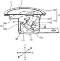
- FIG. 1 is an internal configuration diagram of a horn 1 having a sound source device 10 according to an embodiment of the present invention.
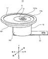
- FIG. 2 is an external configuration diagram of the sound source device 10 shown in FIG.
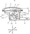
- FIG. 3 is an internal configuration diagram of the sound source device 10 shown in FIG. 4 is a diagram showing a cross section of the bobbin in the internal configuration diagram of FIG.
- the horn 1 will be described with reference to FIGS.
- the upper direction is the upper direction
- the lower direction is the lower direction
- the direction in which the upper and lower directions are collectively referred to as the vertical direction.
- the left direction is referred to as the left direction
- the right direction is referred to as the right direction
- the left direction and the right direction are collectively referred to as the left and right direction with respect to the page.
- the vertical direction and the direction orthogonal to the horizontal direction are referred to as the front-rear direction
- the direction toward the front in the front-rear direction is referred to as the front
- the direction toward the back is referred to as the rear.
- the horn 1 includes a sound source device 10 that generates sound and a resonance tube 20 that is provided above the sound source device 10 and resonates with sound output from the sound source device 10.
- the sound source device 10 includes a diaphragm 11, a movable iron core 12 connected to the diaphragm 11 via a fulcrum region 1211, a fixed iron core 13 provided below the movable iron core 12, a bobbin 14 that constitutes a coil, and a winding.
- a case 16 that accommodates the wire 15, the movable iron core 12, the fixed iron core 13, the bobbin 14, and the winding wire 15; an outer frame 17 that attaches the outer edge of the diaphragm 11 to the outer edge of the case 16;
- a coil case 18 and a bracket 30 attached below the bottom surface of the case 16.
- the diaphragm 11 is made of, for example, a flexible disk-shaped metal, vibrates due to the vibration of the movable iron core 12, and outputs sound.
- the diaphragm 11 is mounted on a circular edge provided on the uppermost side of the case 16 and is fixed to the case 16 by being caulked by the outer frame 17.
- the diaphragm 11 is provided with a taper 11 a in which a certain region surrounding the support portion 121 is inclined in a conical shape downward and is easily vibrated.
- the movable iron core 12 is made of a magnetic material, and includes a support part 121 connected to the diaphragm 11 via a fulcrum region 1211 and a main body part 122 provided below the support part 121.
- the support portion 121 has a columnar shape, and sandwiches the fulcrum region 1211 from both sides in the vertical direction.
- the support portion 121 is provided at a position where the center of the fulcrum region 1211 (hereinafter referred to as “fulcrum 121a”) is eccentric to the right from the center O of the diaphragm 11.
- the direction in which the fulcrum 121a is eccentric (here, the right side) is described as the eccentric direction D1.
- the main body 122 is generally a columnar shape that is longer than the support 121, and the upper end of the center axis C2 is shifted in the eccentric direction D1 with respect to the center axis C1 of the support 121.
- the central axis C1 is directed in the vertical direction, that is, the direction orthogonal to the diaphragm 11, and passes through the fulcrum 121a.
- the central axis C ⁇ b> 2 is inclined obliquely leftward and downward with respect to the vertical direction.
- the gravity center G of the movable iron core 12 is shifted in the eccentric direction D1 from the fulcrum 121a.
- the main body portion 122 includes a cylindrical columnar portion 1222 having a central axis C ⁇ b> 2 as a longitudinal direction, and a bent portion 1221 that is provided above the cylindrical portion 1222 and bends toward the support portion 121.
- the bent portion 1221 protrudes in the eccentric direction D1 in order to shift the center of gravity G in the eccentric direction D1 from the fulcrum 121a. Therefore, the upper surface 1221u of the bent portion 1221 is exposed.
- the fixed iron core 13 includes a pedestal portion 132, a convex portion 131 projecting in the direction of the central axis C2 from the center of the upper surface of the pedestal portion 132, and a fitting portion 133 projecting downward from the lower surface of the pedestal portion 132.
- the pedestal portion 132 has an upper surface 132 a orthogonal to the central axis C ⁇ b> 2 and the bobbin 14 is placed thereon.
- the convex 131 enters the hole 141 provided along the central axis of the bobbin 14 and the bobbin 14 is fitted therein.
- fitting portion 133 is fitted into a hole provided on the bottom surface of case 16. Thereby, the fixed iron core 13 is fixed inside the case 16.
- the bobbin 14 is composed of a drum-shaped member around which the winding wire 15 is wound.
- the movable iron core 12 is inserted into the bobbin 14 from above with respect to the hole 141.
- the diameter of the hole 141 is slightly larger than the diameter of the cylindrical portion 1222 of the movable iron core 12.
- the movable iron core 12 can swing around the fulcrum 121a.
- the lower surface of the cylindrical portion 1222 of the movable iron core 12 is in contact with the upper surface of the convex portion 131.
- a signal generator (not shown) is connected to the winding 15, and a first signal component having a first frequency that resonates with the diaphragm 11 and a second signal component having a second frequency that resonates with the movable iron core 12. Including a driving signal.
- the coil case 18 is provided on the upper side of the pedestal portion 132 so as to cover the upper side of the bobbin 14 and the outer peripheral surface of the winding wire 15.
- a hole for inserting the movable iron core 12 into the bobbin 14 is formed in the center of the upper surface of the coil case 18.
- a packing 181 for supporting the movable iron core 12 is attached to the inner periphery of the hole of the coil case 18 so as to close the space with the movable iron core 12.
- the case 16 includes a disk-shaped upper part 161 and a lower part 162 provided below the upper part 161.
- the upper part 161 has a cross section concentric with the diaphragm 11.
- the lower portion 162 has a cross section that is concentric with the fulcrum 121a, and has a cylindrical shape that is longer in the vertical direction than the upper portion 161.
- the bracket 30 has a strip shape extending rightward from the lower surface of the lower portion 162, and a hole for attaching the horn 1 to the inside of the vehicle is provided at the right end.
- the resonance tube 20 includes a main resonance tube having an opening above the center O of the diaphragm 11 and a branch resonance tube branched from the main resonance tube.
- the main resonance tube and the branch resonance tube are spiral.
- a chord including the first sound and the second sound is input to the main resonance tube.
- the main resonance tube resonates with one of the first sound and the second sound, and outputs one sound from the opening 21.
- the branch resonance tube resonates with either the first sound or the second sound and outputs the other sound from the opening 22.
- the operation of the sound source device 10 shown in FIG. 1 will be briefly described.
- a drive signal from a signal generator (not shown) is applied to the winding 15, the movable iron core 12 is driven by receiving an electromagnetic force from the winding 15.
- the first signal component included in the drive signal has a first frequency that resonates with the diaphragm 11, the diaphragm 11 vibrates in the vertical direction by the movable iron core 12, and the first frequency is set as a fundamental frequency.
- a first sound is generated.
- the second signal component included in the drive signal has a second frequency that resonates with the movable core 12, the movable core 12 swings around the fulcrum 121a. Thereby, the diaphragm 11 generates a second sound having the second frequency as a fundamental frequency.
- an incomplete consonant or a complete consonant may be employed.
- the first and second sounds incomplete harmony with a frequency ratio of 1.25 is employed, but the present invention is not limited to this.
- FIG. 5 is a diagram comparing the sound source device 10 of the present embodiment and the sound source device 10J of the comparative example.
- a characteristic G51 indicates the frequency characteristic of the sound source device 10
- a characteristic G52 indicates the frequency characteristic of the sound source device 10J of the comparative example.
- the vertical axis represents sound pressure
- the horizontal axis represents frequency.
- the sound source device 10J has a movable iron core 12J attached to the center of the diaphragm 11J. Therefore, the characteristic G52 has only one resonance frequency observed in the vicinity of 500 Hz.
- the movable iron core 12 is eccentrically attached to the diaphragm 11 from the center O of the diaphragm 11, and the center of gravity G of the movable iron core 12 is shifted in the eccentric direction D1. Therefore, the characteristic G51 has a resonance frequency due to resonance of the diaphragm 11 observed near 500 Hz and a resonance frequency due to resonance of the movable iron core 12 observed near 400 Hz. Accordingly, the diaphragm 11 generates a chord having a second sound (A sound) due to the resonance of the movable iron core 12 in addition to the first sound (B sound) due to the resonance of the diaphragm 11.
- FIG. 6 is a diagram showing the relationship between the resonance of the length L of the center of gravity G of the movable iron core 12 and the fulcrum 121a.
- the section (a) shown in the first line shows the case where the length L is L1
- the section (b) shown in the second line shows the case where the length L is 0,
- the section shown in the third line (C) shows a case where the length L is 2 ⁇ L1.
- the circle shown at the center indicates the sound pressure distribution 611, 612, 621, 622, 631, 632 of the vibration generated in the diaphragm 11, and as the distance from the center of the concentric circle increases, The sound pressure is low.
- the sound pressure distributions 611, 621, 631 indicate the sound pressure distribution of vibrations (hereinafter referred to as “first vibration”) generated in the diaphragm 11 due to the resonance of the diaphragm 11, and the sound pressure distributions 612, 622, 632. Indicates a sound pressure distribution of vibration (hereinafter referred to as “second vibration”) generated in the diaphragm 11 due to the resonance of the movable iron core 12.
- the frame 651 is a diagram showing the swinging motion of the movable iron core 12.
- the center diagram shows a state S1 (neutral state) in which the movable iron core 12 faces in the up-and-down direction
- the left diagram shows a state S2 in which the movable iron core 12 swings most rightward
- the diagram on the right side shows a state S3 in which the movable iron core 12 is swung to the left.
- states S1 to S3 it can be seen that the movable iron core 12 swings symmetrically due to resonance.
- the vibration of the diaphragm 11 increases in the region on the left side of the fulcrum 121a and increases in the downward direction in the region on the right side of the fulcrum 121a.
- the second vibration has a sound pressure distribution having two peaks symmetrically with respect to the line L6 in the front-rear direction passing through the fulcrum 121a.
- the oscillating motion of the movable iron core 12 can be considered as the oscillating motion of the pendulum with the center of gravity G around the fulcrum 121a. This is shown in the three figures shown in the left column of FIG.
- the center of gravity G coincides with the fulcrum 121a, and the movable iron core 12 does not oscillate. Therefore, as shown in the sound pressure distribution 622, the second vibration does not occur.
- the swinging motion of the movable iron core 12 is considered to be the swinging motion of the pendulum having the center of gravity G. Therefore, when the length L is increased, the resonance frequency of the second vibration generated in the diaphragm 11 by the swinging motion is lowered.
- the second vibration can be generated in the diaphragm 11 by providing the center of gravity G below the fulcrum 121a.
- the center of gravity G is provided directly below the fulcrum 121a, as shown in the states S2 and S3, the second vibration generates amplitude symmetrically with respect to the fulcrum 121a. Therefore, as shown in the schematic diagram 640, the positive vibration and the negative amplitude cancel each other in the second vibration, and the sound due to the second vibration, that is, the second sound is not generated from the diaphragm 11.
- the sound source device 10 has the fulcrum 121a eccentric from the center O of the diaphragm 11 in the eccentric direction D1, as shown in FIG.
- FIG. 7 is a diagram for explaining the operation when the fulcrum 121a is decentered from the center O of the diaphragm 11.
- FIG. Section (a) shows the state of the second vibration when the fulcrum 121a is eccentric from the center O of the diaphragm 11.
- the amplitude of the second vibration is larger on the left side than the right side with respect to the fulcrum 121a.
- the second sound is generated from the diaphragm 11.
- the diaphragm 11 vibrates greatly only in a small area on the left side of the fulcrum 121a, and the second sound with sufficient sound pressure can be obtained. .
- Section (b) of FIG. 7 is a diagram showing the relationship between the eccentric patterns M1, M2, M3 of the center of gravity G of the movable iron core 12 and the sound pressure distributions 721, 722, 723.
- the eccentric pattern M1 is a pattern in which the center of gravity G is shifted in the eccentric direction D1 with respect to the fulcrum 121a, and is the configuration of the present embodiment.
- the eccentric pattern M2 is a pattern in which the center of gravity G is arranged directly below the fulcrum 121a, and is the same pattern as the section (a).
- the eccentric pattern M3 is a pattern in which the center of gravity G is shifted in a direction opposite to the eccentric direction D1 with respect to the fulcrum 121a.
- the sound pressure distribution 722 in the eccentric pattern M2 is the same as the sound pressure distribution 711 in the section (a).
- the diaphragm 11 vibrates greatly as in the eccentric pattern M2.
- the vibration of the diaphragm 11 is smaller than the eccentric pattern M2. Therefore, in the eccentric patterns M2 and M3, the second sound having a sufficient sound pressure cannot be obtained.
- the center of gravity G is shifted to the eccentric direction D1 side. Therefore, when the movable iron core 12 is swung, the diaphragm 11 is greatly pulled by the movable iron core 12 in the region on the right side of the line L7. It is done. Thereby, in the region on the right side of the line L7, the vibration of the diaphragm 11 is larger than the eccentric pattern M2. Thereby, in the eccentric pattern M1, the 2nd sound of sufficient sound pressure is obtained.
- FIG. 8 is a view showing a sound pressure distribution according to the shape of the movable iron core 12.
- the center of gravity G is shifted in the eccentric direction D1, but the shape of the movable iron core 12 is different.
- the shape of the movable iron core 12 is almost the same as the shape shown in FIGS. 1 to 4, but the section (b) is different from the shape shown in FIGS.
- the movable iron core 12 is in a neutral state in which the longitudinal direction is perpendicular to the diaphragm 11, but in FIG. 8, the movable iron core 12 is neutral in both sections (a) and (b). In the state, the longitudinal direction is inclined with respect to the orthogonal direction of the diaphragm 11.
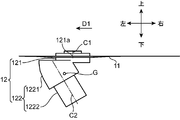
- FIG. 9 is a close-up view of the movable iron core 12 shown in the section (a) of FIG.
- FIG. 10 is a close-up view of the movable iron core 12 shown in the section (b) of FIG.
- the movable core 12 shown in FIG. 9 will be described as the movable core 12 of the first example
- the movable core 12 shown in FIG. 10 will be described as the movable core 12 of the second example.
- the movable iron core 12 of the first example is similar to the movable iron core 12 described above with reference to FIGS. 1 to 4 with respect to the central axis C1 of the support portion 121 and the end portion on the support portion 121 side of the central axis C2 of the main body portion 122.
- the center of gravity G is shifted in the eccentric direction D1 with respect to the fulcrum 121a.
- the movable iron core 12 shown in FIG. 9 has a surface on the fulcrum 121a side of the bent portion 1221 facing the direction parallel to the central axis C2, whereas the movable iron core 12 shown in FIG. Is slightly different in that the surface on the fulcrum 121a side faces in the vertical direction.
- the movable iron core 12 shown in FIG. 9 is not fundamentally different from the movable iron core 12 shown in FIG.
- the center of gravity G is shifted in the eccentric direction D1 by inclining the main body portion 122 with the central axis C2 toward the eccentric direction D1.
- the movable iron core 12 has a cylindrical shape, the center axis C1 is directed in the vertical direction, and is provided with a support portion 121 that passes through the fulcrum 121a as in the first example.
- the movable iron core 12 of the second example includes a substantially cylindrical main body portion 122 whose central axis C2 intersects the central axis C1 at a fulcrum 121a and is inclined toward the eccentric direction D1 side.
- the movable core 12 of the second example has the center of gravity G located on the central axis C2 below the fulcrum 121a, and is shifted to the eccentric direction D1 side with respect to the fulcrum 121a.
- the main body 122 includes an upper cylindrical portion 1221a provided on the support portion 121 side and a lower cylindrical portion 1222a provided below the upper cylindrical portion 1221a.
- the upper cylindrical portion 1221a is made heavier than the lower cylindrical portion 1222a by making the diameter larger than that of the lower cylindrical portion 1222a. Thereby, it is prevented that the position of the center of gravity G is positioned excessively downward.
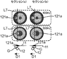
- a large second vibration (here, 400 Hz) is observed in a wide region on the right side of the line L7, which is almost the same. It can be seen that the sound pressure distribution is observed.
- the first vibration (here, 500 Hz) is observed in a wide area around the center O, which is almost the same. It can be seen that the sound pressure distribution is observed.
- FIG. 11 is a diagram comparing the sound pressure distribution of the second vibration due to the difference in the inclination direction of the movable iron core 12.
- Section (a) shows the case where the movable iron core 12 is inclined toward the eccentric direction D1
- section (b) shows the case where the movable iron core 12 is inclined toward the side opposite to the eccentric direction D1.
- the slope pattern of section (a) is referred to as a first slope pattern
- the slope pattern of section (b) is referred to as a second slope pattern.
- the second row shows a neutral state in both inclined patterns
- the third row shows a left maximum swing state in both inclined patterns.
- the center of gravity G is shifted in the eccentric direction D1 by employing the above-described movable iron core 12 of the first example.
- the sound pressure in the region on the right side of the line L7 is slightly higher than that in the second gradient pattern.
- the sound pressure in the region on the left side of the line L7 was slightly lower than that of the second inclined pattern.
- the driving members such as the fixed iron core 13 and the winding wire 15 protrude from the left end of the diaphragm 11.
- the driving members such as the fixed iron core 13 and the winding wire 15 are It can be collected on the center O side. Therefore, the 2nd inclination pattern has the merit that sound source device 10 can be gathered up compactly.
- the component of the force in the left-right direction applied to the diaphragm 11 becomes larger than when the movable iron core 12 is directed vertically. Therefore, the force contributing to the second vibration is increased, and a larger second sound can be generated.
- the diaphragm 11 resonates by the first frequency, and the first sound is output.
- the fulcrum 121a is eccentric from the center O of the diaphragm 11, and the center of gravity G of the movable iron core 12 is shifted from the fulcrum 121a in the eccentric direction D1. Therefore, the movable iron core 12 is swung by the second frequency, and the second sound having a sufficient sound pressure can be output from the diaphragm 11.
- the first frequency and the second frequency have a chordal relationship. Therefore, the sound source device 10 can output a chord including the first and second sounds.
- the movable iron core 12 is inclined, but the movable iron core 12 is not necessarily inclined.
- the movable iron core 12 may face in the up-down direction when neutral. Even in this configuration, the second vibration having a sufficient sound pressure can be obtained as described in the sound pressure distribution 723 of FIG.
- the diameter of the diaphragm 11 may be designed to have a length that resonates with the target first frequency.
- the movable core 12 may be designed to have a full length and a shape so that the length L between the fulcrum 121a and the center of gravity G is a length that resonates with the target second frequency.
Landscapes
- Physics & Mathematics (AREA)
- Engineering & Computer Science (AREA)
- Acoustics & Sound (AREA)
- Multimedia (AREA)
- Electromagnetism (AREA)
- Mechanical Engineering (AREA)
- Audible-Bandwidth Dynamoelectric Transducers Other Than Pickups (AREA)
- Percussion Or Vibration Massage (AREA)
Abstract
本発明の一態様に係るホーン1の音源装置10は、振動板11と、振動板11と支点121aを介して接続された可動鉄心12と、振動板11と共振する第1信号成分と、第1周波数の可動鉄心12と共振し、且つ第1周波数と和音の関係を持つ第2周波数の第2信号成分とを含む駆動信号が入力されるコイル(ボビン14及び巻き線15)とを備える。支点121aは、振動板11の中心Oから偏心した位置に設けられ、可動鉄心12は、支点121aよりも偏心方向D1に重心Gがずれるように構成されている。
Description
本発明は、車両に搭載されるホーンの音源装置に関するものである。
車両には、振動板を可動鉄心で振動させ、振動板で発生した音を共鳴管を通じて外部に出力させるホーンが搭載されている。共鳴管は渦巻き形状を持っているので、水等の異物が侵入して共鳴管内に溜まってしまうと、除去できなくなるという問題がある。そこで、特許文献1は、共鳴管の音波出口開口部に異物侵入防止部材を装着し、車両前方から飛来する異物が共鳴管内に侵入することを防止する車両用電気式ホーンを開示する。
ところで、ホーンから出力される音を和音にすると、搭乗者にとって心地の良い音が出力され、運転の楽しみが増すと考えられる。和音の出力を実現する手法としては、例えば、周波数の異なる音を出力するホーンを複数設ける手法が考えられる。
しかし、この手法ではホーンが複数あるので、コスト及び重量が増大するという問題がある。また、車両においてホーンの設置スペースには限りがあるので、複数のホーンを設けることは好ましくない。
また、特許文献1は、異物の侵入を防止する発明であるので、1つのホーンを用いて和音を出力することはできない。
本発明の目的は、1つの振動板から和音を出力させるホーンの音源装置を提供することである。
本発明の一態様に係る音源装置は、車両に搭載されるホーンの音源装置であって、
振動板と、
前記振動板と支点を介して接続された可動鉄心と、
前記振動板と共振する第1周波数の第1信号成分と、前記可動鉄心と共振し、且つ前記第1周波数と和音の関係を持つ第2周波数の第2信号成分とを含む駆動信号が入力され、
前記可動鉄心を駆動させるコイルとを備え、
前記支点は、振動板の中心から偏心した位置に設けられ、
前記可動鉄心は、前記支点よりも前記支点の偏心方向に重心がずれるように構成されている。
振動板と、
前記振動板と支点を介して接続された可動鉄心と、
前記振動板と共振する第1周波数の第1信号成分と、前記可動鉄心と共振し、且つ前記第1周波数と和音の関係を持つ第2周波数の第2信号成分とを含む駆動信号が入力され、
前記可動鉄心を駆動させるコイルとを備え、
前記支点は、振動板の中心から偏心した位置に設けられ、
前記可動鉄心は、前記支点よりも前記支点の偏心方向に重心がずれるように構成されている。
本態様によれば、第1周波数によって振動板が共振し、第1音が出力される。また、可動鉄心は、第2周波数によって共振し、支点を中心に重心が揺動するように振動する。ここで、支点は振動板の中心から偏心しているので、振動板において、支点に対して偏心方向側の領域(第1領域)の振幅が、支点に対して偏心方向とは反対側の領域(第2領域)の振幅よりも大きくなる。その結果、振動板において、第1領域と第2領域とにおける第2周波数の振動が非対称になって打ち消し合わなくなり、第2音が出力される。
但し、これだけでは、第1領域の面積が小さいので、十分な音圧の第2音が得られない。そこで、本態様では、可動鉄心の重心を偏心方向にずらしている。これにより、揺動時において可動鉄心が第2領域を引っ張る力が増大し、第2領域における第2周波数の振動の振幅が増大し、十分な音圧を持つ第2音が出力できる。更に、第1周波数と第2周波数とは和音の関係を持っている。よって、1つのホーンから第1、第2音を含む和音が出力される。
上記態様において、前記可動鉄心は、前記振動板の直交方向に対して傾斜して配置されていてもよい。
本態様によれば、可動鉄心は斜め方向に傾斜しているので、振動板には、可動鉄心から縦成分の振動に加えて横成分の振動が加えられる。そのため、第2音の音圧をより高くすることができる。
上記態様において、前記可動鉄心は、
前記重心よりも前記振動板側に配置され、前記支点において前記可動鉄心を支持する支持部と、
前記支点とは反対側の前記支持部の端部と接続され、前記支持部の中心軸に対して、中心軸が前記偏心方向にずれて配置された本体部とを備えてもよい。
前記重心よりも前記振動板側に配置され、前記支点において前記可動鉄心を支持する支持部と、
前記支点とは反対側の前記支持部の端部と接続され、前記支持部の中心軸に対して、中心軸が前記偏心方向にずれて配置された本体部とを備えてもよい。
本態様によれば、支持部の中心軸に対して、中心軸をずらして本体部を配置することで、可動鉄心の重心が支点から偏心方向にずらされている。
上記態様において、前記支点と前記重心との長さは、目標の前記第2周波数が得られる長さに設定されていてもよい。
本態様によれば、支点と可動鉄心との長さが目標の第2周波数が得られる長さに設定されているので、振動板から目標となる第2周波数を持つ第2音を出力させることができる。
本発明によれば、1つのホーンから和音を出力することができる。
図1は、本発明の実施の形態における音源装置10を持つホーン1の内部構成図である。図2は、図1に示す音源装置10の外観構成図である。図3は、図2に示す音源装置10の内部構成図である。図4は、図3の内部構成図においてボビンの断面を示した図である。以下、図1~図4を適宜参照しながら、ホーン1を説明する。図1~図4において、紙面に対し、上側の方向を上方、下側の方向を下方、上方及び下方を総称した方向を上下方向と呼ぶ。また、紙面に対し、左側の方向を左方、右側の方向を右方、左方及び右方を総称した方向を左右方向と呼ぶ。更に、上下方向及び左右方向と直交する方向を前後方向と呼び、前後方向において手前に向かう方向を前方、奥側に向かう方向を後方と呼ぶ。
図1に示すように、ホーン1は、音を発生させる音源装置10と、音源装置10の上方に設けられ、音源装置10から出力された音と共鳴する共鳴管20とを備える。
音源装置10は、振動板11と、振動板11と支点領域1211を介して接続された可動鉄心12と、可動鉄心12の下方に設けられた固定鉄心13と、コイルを構成するボビン14及び巻き線15と、可動鉄心12、固定鉄心13、ボビン14、及び巻き線15を収容するケース16と、振動板11の外縁をケース16の外縁に取り付ける外枠17と、ボビン14の上方及び側方を覆うコイルケース18と、ケース16の底面の下方に取り付けられたブラケット30とを備える。
図2を参照し、振動板11は、例えば、可撓性を有する円盤状の金属で構成され、可動鉄心12の振動により振動し、音を出力する。振動板11は、ケース16の最上方に設けられた円形の縁の上に載置され、外枠17によりかしめられることで、ケース16に固定されている。図1を参照し、振動板11は、支持部121を取り囲む一定の領域が下方に向けて円錐状に傾斜したテーパ11aが設けられ、振動し易くされている。
可動鉄心12は、磁性体で構成され、支点領域1211を介して振動板11と接続された支持部121と、支持部121の下側に設けられた本体部122とを備える。
支持部121は、円柱状であり、上下方向の両側から支点領域1211を挟持する。支持部121は、支点領域1211の中心(以下、「支点121a」と記述する。)が振動板11の中心Oよりも右方に偏心した位置に設けられている。ここで、支点121aが偏心した方向(ここでは、右方)を偏心方向D1と記述する。
本体部122は、大局的には、支持部121よりも長い円柱状であり、中心軸C2の上方の端部が支持部121の中心軸C1に対して、偏心方向D1にずれている。なお、中心軸C1は上下方向、すなわち、振動板11と直交する方向を向いており、且つ、支点121aを通過している。図1の例では、中心軸C2は、上下方向に対して左斜め下方に傾斜している。これにより、可動鉄心12の重心Gは、支点121aよりも偏心方向D1にずらされる。具体的には、本体部122は、中心軸C2を長手方向とする円柱状の円柱部1222と、円柱部1222の上方に設けられ、支持部121に向けて屈曲する屈曲部1221とを備える。
図1の例では、重心Gを支点121aよりも偏心方向D1にずらすために、屈曲部1221は、偏心方向D1に突出している。そのため、屈曲部1221の上面1221uは露出している。
固定鉄心13は、台座部132と、台座部132の上面の中心から中心軸C2の方向に突出した凸部131と、台座部132の下面から下方に突出した嵌合部133とを備える。図4を参照し、台座部132は、中心軸C2と直交する上面132aを持ち、ボビン14が載置される。凸部131は、ボビン14の中心軸に沿って設けられた穴141内に侵入し、ボビン14が嵌め込まれる。図1を参照して、嵌合部133は、ケース16の底面に設けられた穴に嵌め込まれる。これにより、固定鉄心13がケース16の内部で固定される。
ボビン14は、巻き線15が巻回されたドラム状の部材で構成されている。図3を参照し、ボビン14は、穴141に対して上方から可動鉄心12が挿入されている。穴141の直径は、可動鉄心12の円柱部1222の直径よりも多少大きくされている。これにより、可動鉄心12は、中心軸C2に沿った振動に加えて、支点121aを中心とする揺動が可能とされている。図4を参照し、可動鉄心12の円柱部1222は、下面が凸部131の上面と当接している。巻き線15には、図略の信号生成装置が接続されており、振動板11と共振する第1周波数の第1信号成分と、可動鉄心12と共振する第2周波数の第2信号成分とを含む駆動信号が入力される。
図1を参照し、コイルケース18は、ボビン14の上方及び巻き線15の外周面を覆うように、台座部132の上側に設けられている。コイルケース18の上面の中央には、可動鉄心12をボビン14に挿入するための穴が形成されている。また、コイルケース18の穴の内周には可動鉄心12との空間を閉塞して、可動鉄心12を支持するパッキン181が取り付けられている。
図2を参照し、ケース16は、円盤状の上部161と、上部161の下方に設けられた下部162とを備える。上部161は、振動板11と同心円状の断面を持つ。下部162は、支点121aと同心円状の断面を持ち、上部161よりも上下方向の長さが長い円柱形状を持つ。
ブラケット30は、下部162の下面から右方に延びる短冊形状を持ち、右端にホーン1を車両の内部に取り付けるための穴が設けられている。
図1を参照し、共鳴管20は、振動板11の中心Oの上側に開口部を持つ主共鳴管と、主共鳴管から分岐した分岐共鳴管とを備える。主共鳴管及び分岐共鳴管は渦巻き状である。主共鳴管には、第1音と第2音とを含む和音が入力される。主共鳴管は、第1音及び第2音のいずれか一方の音と共鳴して、開口部21から一方の音を出力する。分岐共鳴管は、第1音及び第2音のいずれか他方の音と共鳴して、開口部22から他方の音を出力する。
図1に示す音源装置10の動作を簡単に説明する。図略の信号生成装置からの駆動信号が巻き線15に印加されると、可動鉄心12は巻き線15からの電磁気力を受けて駆動される。ここで、駆動信号に含まれる第1信号成分は、振動板11と共振する第1周波数を持っているので、振動板11は可動鉄心12によって上下方向に振動し、第1周波数を基本周波数とする第1音を発生する。また、駆動信号に含まれる第2信号成分は、可動鉄心12と共振する第2周波数を持っているので、可動鉄心12は、支点121aを中心に揺動する。これにより、振動板11は第2周波数を基本周波数とする第2音を発生する。
第1周波数と第2周波数としては、不完全協和音を採用してもよいし、完全協和音を採用してもよい。ここでは、第1、第2音として、周波数比が1.25の関係を持つ不完全協和音を採用するが、これに限定されない。
図5は、本実施の形態の音源装置10と比較例の音源装置10Jとを比較した図である。図5のグラフにおいて、特性G51は音源装置10の周波数特性を示し、特性G52は比較例の音源装置10Jの周波数特性を示している。なお、図5のグラフにおいて、縦軸は音圧を示し、横軸は周波数を示している。
音源装置10Jは、可動鉄心12Jが振動板11Jの中心に取り付けられている。そのため、特性G52は500Hz付近で観測される1つの共振周波数しか持っていない。一方、音源装置10は、可動鉄心12が振動板11の中心Oから偏心して振動板11に取り付けられ、かつ、可動鉄心12の重心Gが偏心方向D1にずれている。そのため、特性G51は、500Hz付近で観測される振動板11の共振による共振周波数と、400Hz付近で観測される可動鉄心12の共振による共振周波数とを持つ。これにより、振動板11は振動板11の共振による第1音(B音)に加えて、可動鉄心12の共振による第2音(A音)を持つ和音を発生する。
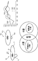
図6は、可動鉄心12の重心Gと支点121aとの長さLと、共振との関係を示した図である。1行目に示すセクション(a)は、長さLをL1にした場合を示し、2行目に示すセクション(b)は、長さLを0にした場合を示し、3行目に示すセクション(c)は長さLを2・L1にした場合を示している。また、セクション(a)~セクション(c)において、中央に示す円は振動板11で発生する振動の音圧分布611,612,621,622,631,632を示し、同心円の中心から離れるにつれて、音圧が低くなっている。音圧分布611,621,631は、振動板11の共振により振動板11で発生する振動(以下、「第1振動」と呼ぶ。)の音圧分布を示し、音圧分布612,622,632は、可動鉄心12の共振により振動板11で発生する振動(以下、「第2振動」と呼ぶ。)の音圧分布を示している。
枠651は、可動鉄心12の揺動運動を示した図である。枠651の例では、中央の図は、可動鉄心12が上下方向を向いた状態S1(中立状態)を示し、左側の図は、可動鉄心12が最も右方に揺動した状態S2を示し、右側の図は、可動鉄心12が最も左方に揺動した状態S3を示している。状態S1~S3に示すように、可動鉄心12は、共振により、左右対称に揺動していることが分かる。
詳細には、振動板11は、状態S1から状態S2に向かうにつれて、支点121aよりも左側の領域における下方への撓みが増大していくと共に、支点121aよりも右側の領域における上方への撓みが増大していく。また、状態S1から状態S3に向かうにつれて、振動板11は、支点121aよりも左側の領域における上方への撓みが増大していくと共に、支点121aよりも右側の領域における下方への撓みが増大していく。これにより、音圧分布612,632に示すように、第2振動は、支点121aを通過する前後方向の線L6に対して対称に2つのピークを持つ音圧分布を持つことになる。
可動鉄心12は、支点121aを中心に左右方向に揺動するので、可動鉄心12の揺動運動は、支点121aを中心とする重心Gの振り子の揺動運動と考えることができる。それを示したのが図6の左列に示した3つの図である。
セクション(a)の例では、長さL=L1の振り子の揺動運動により第2振動の共振周波数は、音圧分布612に示すように、255Hzであった。一方、セクション(c)の例では、長さがセクション(a)の2倍なので、第2振動の共振周波数は、音圧分布632に示すように、セクション(a)の1/2の共振周波数(=128Hz)になった。また、セクション(b)の例では、重心Gが支点121aと一致しており、可動鉄心12は揺動しないので、音圧分布622に示すように、第2振動は発生しなかった。
このように、可動鉄心12の揺動運動は重心Gの振り子の揺動運動と考えられるので、長さLを長くすると、揺動運動により振動板11に発生する第2振動の共振周波数が低くなることが分かる。
一方、第1振動は、振動板11の共振によるものであり、可動鉄心12の揺動運動に依存しないので、セクション(a)~(c)とも、227Hzの同じ共振周波数が得られている。
このように、重心Gを支点121aの下方に設けることで、第2振動を振動板11に発生させることができる。しかし、重心Gを支点121aの真下に設けると、状態S2,S3に示すように、第2振動は、支点121aを中心に点対称に振幅が発生する。そのため、模式図640に示すように、第2振動は、プラスの振幅とマイナスの振幅とが打ち消し合い、振動板11からは第2振動による音、すなわち、第2音は発生しなくなってしまう。
そこで、音源装置10は、図7に示すように、支点121aを振動板11の中心Oから偏心方向D1に偏心させている。図7は、支点121aを振動板11の中心Oから偏心させた場合の作用を説明する図である。セクション(a)は、支点121aを振動板11の中心Oから偏心させた場合の第2振動の様子を示している。セクション(a)の例では、支点121aが、中心Oから偏心方向D1(ここでは、左方)にずらされている。この場合、第2振動の振幅は、模式図730及び音圧分布711に示すように、支点121aに対して左側の方が右側よりも大きくなって、非対称になるので、第2振動は打ち消し合わず、振動板11から第2音が発生する。但し、第2音の音圧は振動面積×振幅で決まるので、支点121aよりも左側の小さい領域でしか振動板11は大きく振動しておらず、十分な音圧の第2音が得られない。
そこで、音源装置10は、可動鉄心12の重心Gを偏心方向D1側にずらしている。図7のセクション(b)は、可動鉄心12の重心Gの偏心パターンM1,M2,M3と音圧分布721,722,723との関係を示す図である。偏心パターンM1は、支点121aに対して、重心Gを偏心方向D1にずらしたパターンであり、本実施の形態の構成である。偏心パターンM2は、重心Gを支点121aの真下に配置したパターンであり、セクション(a)と同じパターンである。偏心パターンM3は、支点121aに対して、重心Gを偏心方向D1とは反対の方向にずらしたパターンである。
偏心パターンM2における音圧分布722は、セクション(a)の音圧分布711と同じである。偏心パターンM3では、音圧分布721に示すように、支点121aを通る前後方向の線L7よりも左側の領域において、振動板11は、偏心パターンM2と同様に、大きく振動しているが、線L7よりも右側の領域において、振動板11の振動は偏心パターンM2よりも小さくなっている。したがって、偏心パターンM2,M3では、十分な音圧を持つ第2音が得られない。
これに対し、偏心パターンM1では、重心Gが偏心方向D1側にずらされているので、可動鉄心12の揺動時に、振動板11は、線L7よりも右側の領域が可動鉄心12により大きく引っ張られる。これにより、線L7よりも右側の領域において、振動板11の振動は偏心パターンM2よりも大きくなっている。これにより、偏心パターンM1では、十分な音圧の第2音が得られる。
図8は、可動鉄心12の形状に応じた音圧分布を示した図である。セクション(a)、(b)とも、重心Gは、偏心方向D1にずらされているが、可動鉄心12の形状が異なっている。セクション(a)では、可動鉄心12の形状は、図1~図4で示した形状とほぼ同一であるが、セクション(b)は、図1~図4で示した形状と異なっている。また、図7では、可動鉄心12は、中立状態において、長手方向が振動板11の直交方向を向いているが、図8は、セクション(a)、(b)とも、可動鉄心12は、中立状態において、長手方向が振動板11の直交方向に対して傾斜している。
図9は、図8のセクション(a)に示す可動鉄心12をクローズアップして示した図である。図10は、図8のセクション(b)に示す可動鉄心12をクローズアップして示した図である。以下、図9に示す可動鉄心12を第1例の可動鉄心12、図10に示す可動鉄心12を第2例の可動鉄心12として説明する。
第1例の可動鉄心12は、図1~図4で上述した可動鉄心12と同様、支持部121の中心軸C1に対して、本体部122の中心軸C2の支持部121側の端部を偏心方向D1にずらすことで、重心Gが支点121aに対して偏心方向D1にずらされている。但し、図9に示す可動鉄心12は、屈曲部1221の支点121a側の面が、中心軸C2と平行な方向を向いているのに対して、図1に示す可動鉄心12は、屈曲部1221の支点121a側の面が上下方向を向いている点で若干相違している。それ以外、図9に示す可動鉄心12は、図1に示す可動鉄心12に対して、本質的な相違はないので、詳細な説明を省く。
第2例の可動鉄心12は、本体部122を中心軸C2を偏心方向D1側に傾斜させることで重心Gが偏心方向D1にずらされている。詳細には、可動鉄心12は、円柱状であり、中心軸C1が上下方向を向いており、支点121aを通過する支持部121を備えている点は第1例と同じである。
また、第2例の可動鉄心12は、中心軸C2が支点121aで中心軸C1と交差し、且つ、偏心方向D1側に傾斜するほぼ円柱状の本体部122を備えている。これにより、第2例の可動鉄心12は、重心Gが、支点121aの下方の中心軸C2上に位置することになり、支点121aに対して偏心方向D1側にずれることになる。より詳細には、本体部122は、支持部121側に設けられた上円柱部1221aと、上円柱部1221aの下方に設けられた下円柱部1222aとを備えている。
ここで、上円柱部1221aは、下円柱部1222aよりも直径を大きくすることで、下円柱部1222aより重くされている。これにより、重心Gの位置が過剰に下方に位置することが防止されている。
図8の1行目に示すように、第1、第2例の可動鉄心12は、線L7よりも右側の広い領域で大きな第2振動(ここでは、400Hz)が観測されており、ほぼ同じ音圧分布が観測されていることが分かる。また、図8の2行目に示すように、第1、第2例の可動鉄心12は、中心Oを中心に広い領域で第1振動(ここでは、500Hz)が観測されており、ほぼ同じ音圧分布が観測されていることが分かる。
図8のセクション(a)、(b)を比較すれば分かるように、可動鉄心12の形状が異なっていても、重心Gが支点121aよりも偏心方向D1にずれていれば、高い音圧の第1、第2振動が得られ、第1音、第2音を発生させることができる。
図11は、可動鉄心12の傾斜方向の違いによる第2振動の音圧分布を比較した図である。セクション(a)は、可動鉄心12を偏心方向D1側に傾斜させた場合を示し、セクション(b)は、可動鉄心12を偏心方向D1とは反対側に傾斜させた場合を示す。以下、セクション(a)の傾斜パターンを第1傾斜パターンと呼び、セクション(b)の傾斜パターンを第2傾斜パターンと呼ぶ。なお、図11において、2行目は、両傾斜パターンにおける中立状態を示し、3行目は、両傾斜パターンにおける左の最大揺動状態を示している。また、第1、第2傾斜パターンとも、上述した第1例の可動鉄心12を採用することで、重心Gが偏心方向D1にずらされている。
セクション(a)、(b)の音圧分布1101,1102を比較すれば分かるように、第1傾斜パターンは、線L7よりも右側の領域における音圧が第2傾斜パターンよりも多少高かったが、線L7よりも左側の領域における音圧が第2傾斜パターンよりも多少低かった。これらの差は、第1、第2傾斜パターンにおける、支点121aに対する偏心方向D1への重心Gのずれ量の相違が原因と考えられる。いずれにせよ、両傾斜パターンとも、トータルでは、十分な音圧を持つ第2振動が得られていることが分かる。
但し、セクション(a)に示すように、第1傾斜パターンでは、可動鉄心12が偏心方向D1側にずれているので、固定鉄心13及び巻き線15等の駆動部材が振動板11の左端からはみ出す可能性がある。一方、セクション(b)に示すように、第2傾斜パターンでは、可動鉄心12が偏心方向D1とは反対側にずれているので、固定鉄心13及び巻き線15等の駆動部材が振動板11の中心O側に集めることができる。そのため、第2傾斜パターンは、音源装置10をコンパクトに纏めることができるといったメリットが得られる。
第1、第2傾斜パターンで示すように、可動鉄心12を傾斜させた場合、振動板11に加わる左右方向の力の成分が可動鉄心12を上下方向に向けた場合に比べて大きくなる。そのため、第2振動に寄与する力が増大し、より大きな第2音を発生させることができる。
以上説明した音源装置10によれば、第1周波数によって、振動板11が共振し、第1音が出力される。また、支点121aが振動板11の中心Oから偏心し、且つ、可動鉄心12の重心Gが支点121aよりも偏心方向D1にずれている。そのため、第2周波数によって可動鉄心12が揺動し、振動板11から十分な音圧を持つ第2音を出力できる。更に、第1周波数と第2周波数とは和音の関係を持っている。よって、音源装置10は、第1、第2音を含む和音を出力できる。
<補足>
(1)図1の例では、可動鉄心12は傾斜しているが、必ずしも可動鉄心12は傾斜している必要はない。例えば、図7の偏心パターンM1に示すように、可動鉄心12は、中立時に、上下方向を向いていても良い。この構成においても、図7の音圧分布723で説明したように十分な音圧を持つ第2振動が得られる。
(1)図1の例では、可動鉄心12は傾斜しているが、必ずしも可動鉄心12は傾斜している必要はない。例えば、図7の偏心パターンM1に示すように、可動鉄心12は、中立時に、上下方向を向いていても良い。この構成においても、図7の音圧分布723で説明したように十分な音圧を持つ第2振動が得られる。
(2)振動板11の直径は、目標の第1周波数と共振する長さとなるように設計されればよい。また、可動鉄心12は、支点121a及び重心G間の長さLが、目標の第2周波数と共振する長さとなるように、全長及び形状が設計されればよい。
C1 中心軸
C2 中心軸
D1 偏心方向
G 重心
O 中心
1 ホーン
10 音源装置
11 振動板
12 可動鉄心
13 固定鉄心
14 ボビン
15 巻き線
16 ケース
17 外枠
18 コイルケース
20 共鳴管
30 ブラケット
121 支持部
121a 支点
122 本体部
1211 支点領域
1221 屈曲部
1221a 上円柱部
1222 円柱部
1222a 下円柱部
C2 中心軸
D1 偏心方向
G 重心
O 中心
1 ホーン
10 音源装置
11 振動板
12 可動鉄心
13 固定鉄心
14 ボビン
15 巻き線
16 ケース
17 外枠
18 コイルケース
20 共鳴管
30 ブラケット
121 支持部
121a 支点
122 本体部
1211 支点領域
1221 屈曲部
1221a 上円柱部
1222 円柱部
1222a 下円柱部
Claims (4)
- 車両に搭載されるホーンの音源装置であって、
振動板と、
前記振動板と支点を介して接続された可動鉄心と、
前記振動板と共振する第1周波数の第1信号成分と、前記可動鉄心と共振し、且つ前記第1周波数と和音の関係を持つ第2周波数の第2信号成分とを含む駆動信号が入力され、前記可動鉄心を駆動させるコイルとを備え、
前記支点は、振動板の中心から偏心した位置に設けられ、
前記可動鉄心は、前記支点よりも前記支点の偏心方向に重心がずれるように構成されている音源装置。 - 前記可動鉄心は、前記振動板の直交方向に対して傾斜して配置されている請求項1記載の音源装置。
- 前記可動鉄心は、
前記重心よりも前記振動板側に配置され、前記支点において前記可動鉄心を支持する支持部と、
前記支点とは反対側の前記支持部の端部と接続され、前記支持部の中心軸に対して、中心軸が前記偏心方向にずれて配置された本体部とを備える請求項1又は2記載の音源装置。 - 前記支点と前記重心との長さは、目標の前記第2周波数の得られる長さに設定されている請求項1~3のいずれかに記載の音源装置。
Priority Applications (3)
| Application Number | Priority Date | Filing Date | Title |
|---|---|---|---|
| CN201780003082.7A CN107924672B (zh) | 2016-03-25 | 2017-03-06 | 喇叭的音源装置 |
| DE112017000219.2T DE112017000219B4 (de) | 2016-03-25 | 2017-03-06 | Hupen-Schallquellenvorrichtung |
| US15/761,072 US10166816B2 (en) | 2016-03-25 | 2017-03-06 | Sound source device of horn |
Applications Claiming Priority (2)
| Application Number | Priority Date | Filing Date | Title |
|---|---|---|---|
| JP2016-061618 | 2016-03-25 | ||
| JP2016061618A JP6197904B1 (ja) | 2016-03-25 | 2016-03-25 | ホーンの音源装置 |
Publications (1)
| Publication Number | Publication Date |
|---|---|
| WO2017163840A1 true WO2017163840A1 (ja) | 2017-09-28 |
Family
ID=59895702
Family Applications (1)
| Application Number | Title | Priority Date | Filing Date |
|---|---|---|---|
| PCT/JP2017/008787 Ceased WO2017163840A1 (ja) | 2016-03-25 | 2017-03-06 | ホーンの音源装置 |
Country Status (5)
| Country | Link |
|---|---|
| US (1) | US10166816B2 (ja) |
| JP (1) | JP6197904B1 (ja) |
| CN (1) | CN107924672B (ja) |
| DE (1) | DE112017000219B4 (ja) |
| WO (1) | WO2017163840A1 (ja) |
Families Citing this family (3)
| Publication number | Priority date | Publication date | Assignee | Title |
|---|---|---|---|---|
| JP6274285B1 (ja) * | 2016-09-30 | 2018-02-07 | マツダ株式会社 | ホーンの音源装置、およびこれを備えたホーン |
| KR102471391B1 (ko) * | 2018-02-21 | 2022-11-29 | 현대자동차주식회사 | 차량용 경음기 |
| US11881204B2 (en) * | 2020-07-30 | 2024-01-23 | Ford Global Technologies, Llc | Dual-tone horn assemblies and methods of use |
Citations (3)
| Publication number | Priority date | Publication date | Assignee | Title |
|---|---|---|---|---|
| JPS5193674U (ja) * | 1975-01-25 | 1976-07-27 | ||
| JP2000318517A (ja) * | 1999-05-07 | 2000-11-21 | Mitsuba Corp | 車両用ホーン |
| JP2012088490A (ja) * | 2010-10-19 | 2012-05-10 | Denso Corp | 車両用警報装置 |
Family Cites Families (14)
| Publication number | Priority date | Publication date | Assignee | Title |
|---|---|---|---|---|
| AU4159600A (en) * | 1999-03-29 | 2000-10-16 | Telefonaktiebolaget Lm Ericsson (Publ) | Vertical buzzer/earphone to reduce humming sounds |
| IT1318298B1 (it) * | 2000-08-01 | 2003-07-28 | Fiamm Spa | Avvisatore acustico elettromeccanico. |
| CN2683453Y (zh) * | 2003-12-16 | 2005-03-09 | 金锡昆 | 一种车辆无触点电喇叭 |
| CN2850186Y (zh) * | 2005-11-22 | 2006-12-20 | 李永慎 | 电喇叭 |
| DE102009008748A1 (de) | 2009-02-13 | 2010-08-26 | Volkswagen Ag | Verfahren zur Bestimmung einer Resonanzfrequenz einer Tonerzeugungseinrichtung und Verfahren zur Ansteuerung einer Tonerzeugungseinrichtung sowie entsprechend ausgestaltete Ansteuervorrichtung und entsprechend ausgestaltete Tonerzeugungseinrichtung |
| JP2010252034A (ja) | 2009-04-15 | 2010-11-04 | Onkyo Corp | スピーカー振動板およびこれを用いた動電型スピーカー |
| JP5410230B2 (ja) | 2009-10-02 | 2014-02-05 | 浜名湖電装株式会社 | 車両用電気式ホーン |
| JP5563939B2 (ja) * | 2010-09-22 | 2014-07-30 | 株式会社ミツバ | ホーン |
| JP2012080480A (ja) * | 2010-10-06 | 2012-04-19 | Sony Corp | スピーカーユニット及びアクティブスピーカー装置 |
| JP5287914B2 (ja) * | 2011-03-22 | 2013-09-11 | 株式会社デンソー | 車両存在通報装置 |
| DE102012013392A1 (de) * | 2012-07-05 | 2014-01-09 | GM Global Technology Operations LLC (n. d. Ges. d. Staates Delaware) | Elektrische Hornvorrichtung für einFahrzeug und Fahrzeug |
| JP6359923B2 (ja) * | 2014-09-12 | 2018-07-18 | 株式会社ミツバ | ホーン装置 |
| JP2016218110A (ja) * | 2015-05-14 | 2016-12-22 | 浜名湖電装株式会社 | 車両用警音器 |
| JP6373814B2 (ja) * | 2015-10-05 | 2018-08-15 | 丸子警報器株式会社 | 車両用ホーン |
-
2016
- 2016-03-25 JP JP2016061618A patent/JP6197904B1/ja active Active
-
2017
- 2017-03-06 CN CN201780003082.7A patent/CN107924672B/zh active Active
- 2017-03-06 US US15/761,072 patent/US10166816B2/en active Active
- 2017-03-06 WO PCT/JP2017/008787 patent/WO2017163840A1/ja not_active Ceased
- 2017-03-06 DE DE112017000219.2T patent/DE112017000219B4/de active Active
Patent Citations (3)
| Publication number | Priority date | Publication date | Assignee | Title |
|---|---|---|---|---|
| JPS5193674U (ja) * | 1975-01-25 | 1976-07-27 | ||
| JP2000318517A (ja) * | 1999-05-07 | 2000-11-21 | Mitsuba Corp | 車両用ホーン |
| JP2012088490A (ja) * | 2010-10-19 | 2012-05-10 | Denso Corp | 車両用警報装置 |
Also Published As
| Publication number | Publication date |
|---|---|
| US20180257559A1 (en) | 2018-09-13 |
| DE112017000219B4 (de) | 2022-01-13 |
| JP2017173688A (ja) | 2017-09-28 |
| CN107924672B (zh) | 2022-01-14 |
| DE112017000219T5 (de) | 2018-08-16 |
| US10166816B2 (en) | 2019-01-01 |
| JP6197904B1 (ja) | 2017-09-20 |
| CN107924672A (zh) | 2018-04-17 |
Similar Documents
| Publication | Publication Date | Title |
|---|---|---|
| US20180170228A1 (en) | Vibration generator | |
| JPWO2009016743A1 (ja) | スピーカ装置 | |
| CN107404693A (zh) | 辐射器及双悬边扬声器和音箱及其应用 | |
| KR20120113232A (ko) | 복합 스피커 | |
| JP6197904B1 (ja) | ホーンの音源装置 | |
| JP2018207265A (ja) | スピーカ | |
| JP2006005852A (ja) | スピーカー装置 | |
| JP6197905B1 (ja) | ホーンの共鳴管 | |
| JP6274285B1 (ja) | ホーンの音源装置、およびこれを備えたホーン | |
| JP5626787B2 (ja) | スピーカ | |
| JP2009284064A (ja) | スピーカ | |
| KR102471391B1 (ko) | 차량용 경음기 | |
| JP6249074B1 (ja) | ホーンの共鳴管、およびこれを備えたホーン | |
| JP7126762B2 (ja) | 音響用の加振装置および前記加振装置を使用した発音装置 | |
| JP4597776B2 (ja) | スピーカ | |
| KR101345335B1 (ko) | 스피커 | |
| KR101722527B1 (ko) | 박형 스피커 | |
| JP7350428B2 (ja) | 音響用の加振装置および前記加振装置を使用した車載音響装置 | |
| JP2005175859A (ja) | スピーカ用振動板の駆動体および該駆動体を使用したスピーカ | |
| US1719227A (en) | Loud-speaker unit | |
| JP5178108B2 (ja) | 振動板及びこれを備えたスピーカ | |
| JPS6162298A (ja) | スピ−カ装置 | |
| JP6339990B2 (ja) | 車両用ホーン | |
| JP2024017030A (ja) | スピーカー装置、及び、スピーカー装置の製造方法 | |
| TWI483626B (zh) | 具懸邊改良結構之振膜 |
Legal Events
| Date | Code | Title | Description |
|---|---|---|---|
| WWE | Wipo information: entry into national phase |
Ref document number: 15761072 Country of ref document: US |
|
| WWE | Wipo information: entry into national phase |
Ref document number: 112017000219 Country of ref document: DE |
|
| 121 | Ep: the epo has been informed by wipo that ep was designated in this application |
Ref document number: 17769885 Country of ref document: EP Kind code of ref document: A1 |
|
| 122 | Ep: pct application non-entry in european phase |
Ref document number: 17769885 Country of ref document: EP Kind code of ref document: A1 |