WO2017163437A1 - 放射能汚染検査装置 - Google Patents
放射能汚染検査装置 Download PDFInfo
- Publication number
- WO2017163437A1 WO2017163437A1 PCT/JP2016/068963 JP2016068963W WO2017163437A1 WO 2017163437 A1 WO2017163437 A1 WO 2017163437A1 JP 2016068963 W JP2016068963 W JP 2016068963W WO 2017163437 A1 WO2017163437 A1 WO 2017163437A1
- Authority
- WO
- WIPO (PCT)
- Prior art keywords
- measurement
- radioactive contamination
- detection unit
- unit
- inspection apparatus
- Prior art date
- Legal status (The legal status is an assumption and is not a legal conclusion. Google has not performed a legal analysis and makes no representation as to the accuracy of the status listed.)
- Ceased
Links
Images


Classifications
-
- G—PHYSICS
- G01—MEASURING; TESTING
- G01T—MEASUREMENT OF NUCLEAR OR X-RADIATION
- G01T1/00—Measuring X-radiation, gamma radiation, corpuscular radiation, or cosmic radiation
- G01T1/16—Measuring radiation intensity
- G01T1/169—Exploration, location of contaminated surface areas
-
- G—PHYSICS
- G01—MEASURING; TESTING
- G01B—MEASURING LENGTH, THICKNESS OR SIMILAR LINEAR DIMENSIONS; MEASURING ANGLES; MEASURING AREAS; MEASURING IRREGULARITIES OF SURFACES OR CONTOURS
- G01B11/00—Measuring arrangements characterised by the use of optical techniques
- G01B11/26—Measuring arrangements characterised by the use of optical techniques for measuring angles or tapers; for testing the alignment of axes
-
- G—PHYSICS
- G01—MEASURING; TESTING
- G01C—MEASURING DISTANCES, LEVELS OR BEARINGS; SURVEYING; NAVIGATION; GYROSCOPIC INSTRUMENTS; PHOTOGRAMMETRY OR VIDEOGRAMMETRY
- G01C3/00—Measuring distances in line of sight; Optical rangefinders
- G01C3/02—Details
-
- G—PHYSICS
- G01—MEASURING; TESTING
- G01T—MEASUREMENT OF NUCLEAR OR X-RADIATION
- G01T1/00—Measuring X-radiation, gamma radiation, corpuscular radiation, or cosmic radiation
- G01T1/16—Measuring radiation intensity
- G01T1/167—Measuring radioactive content of objects, e.g. contamination
-
- G—PHYSICS
- G01—MEASURING; TESTING
- G01T—MEASUREMENT OF NUCLEAR OR X-RADIATION
- G01T1/00—Measuring X-radiation, gamma radiation, corpuscular radiation, or cosmic radiation
- G01T1/16—Measuring radiation intensity
- G01T1/20—Measuring radiation intensity with scintillation detectors
-
- G—PHYSICS
- G01—MEASURING; TESTING
- G01T—MEASUREMENT OF NUCLEAR OR X-RADIATION
- G01T1/00—Measuring X-radiation, gamma radiation, corpuscular radiation, or cosmic radiation
- G01T1/16—Measuring radiation intensity
- G01T1/24—Measuring radiation intensity with semiconductor detectors
-
- G—PHYSICS
- G01—MEASURING; TESTING
- G01T—MEASUREMENT OF NUCLEAR OR X-RADIATION
- G01T7/00—Details of radiation-measuring instruments
Definitions
- the present invention relates to an apparatus for inspecting the presence or absence of radioactive contamination of an object by detecting radiation, and in particular, considering the case where a transport vehicle is withdrawn from a management area at a decommissioning site or an intermediate storage facility.
- the present invention relates to a radioactive contamination inspection apparatus.
- the Ionizing Radiation Hazard Prevention Regulation stipulates that if a radioactivity exceeding a certain value is handled, a control area is set up and if an article is taken out of the control area, the contamination due to the radioactivity is inspected. . Therefore, article inspection monitors are used in nuclear facilities.
- Patent Documents 1 to 4 Patent Documents 1 to 4). 4).
- Patent Document 1 discloses a method of measuring the radioactivity concentration (surface contamination density) on the surface of an object to be measured using a detector sensitive to ⁇ rays or ⁇ rays.
- Patent Document 2 discloses a method of performing measurement by placing a measurement object in a container formed of a scintillation detector that can be deformed in order to inspect the measurement object having a complicated shape.
- Patent Document 3 discloses a method of detecting the characteristic X-rays emitted with the decay of radioactive cesium and measuring the radioactivity concentration on the measurement target surface or inside the measurement target.
- Patent Document 4 discloses a method for measuring the radioactivity concentration (surface contamination density) on the surface of an object using a ⁇ -ray (X-ray) camera in which elements sensitive to ⁇ -rays or X-rays are arranged in an array. It is shown.
- Patent Document 5 there is a conventional technique related to a plastic scintillator and an optical fiber type large area radiation monitor capable of measuring radiation with high sensitivity and uniformity over the entire detection section (large area) (see, for example, Patent Document 5).
- this patent document 5 light emitted from a plastic scintillator is collected by an optical fiber, and the plastic scintillator and the optical fiber are molded in accordance with the shape of the measurement object, whereby the radiation of the measurement object having a curved surface shape is obtained. Can be measured.
- JP 2005-172771 A Japanese Patent No. 5669782 Japanese Patent Laying-Open No. 2015-180872 No. 5400988 Japanese Patent Laid-Open No. 9-243752
- the size of the detector, the condensing device, and the optoelectronic converter is increased, and it is difficult to physically approach a narrow portion, and it is difficult to accurately measure the measurement object having a complicated shape. Therefore, for example, in the case of a narrow portion such as a tire house of a vehicle or the bottom surface of a vehicle, or a surface having a complicated shape such as a mixer car, the prior art disclosed in the above Patent Documents 1 to 4 is used. The method failed to check for radioactive contamination.
- Patent Document 5 a laminated plastic scintillator and a radiation detection optical fiber that can change the shape of the sensitive region have been proposed in order to perform surface contamination inspection of narrow portions and curved surfaces.
- the object to be measured is ⁇ -ray and is affected by environmental radiation, there is a problem that the detection limit cannot be made sufficiently lower than the reference value.
- a radiation detector using laminated plastic scintillators and optical fibers needs to be shielded reliably and has poor light collection efficiency, so that it is difficult to realize a practical one.
- the present invention has been made to solve the above-described problems.
- the shape of a vehicle tire house, the bottom of a vehicle, or the like is complicated, and it is difficult to bring a normal radiation detector close to the device.
- the object is to obtain a radioactive contamination inspection apparatus capable of efficiently performing contamination inspection of a part.
- the detection unit having the shape of the sensitive surface matched to the shape of the object surface to be measured for the amount of radioactive contamination, and the distance from the sensitive surface to the object surface are preset.
- a mechanism unit that holds the detection unit in a state within the desired range, and a measurement unit that calculates the amount of radioactive contamination on the surface of the object based on the measurement result of the detection unit.
- the detection unit having the shape of the sensitive surface matched to the shape of the object surface that is the measurement target of the radioactive contamination amount is in a state where the distance from the sensitive surface to the object surface is within the desired range. It has a configuration that can be held. By having such a configuration, the thickness of the measuring device can be reduced compared to the conventional one, and the area and shape of the semiconductor detector necessary for ensuring the detection efficiency can be determined according to the detection efficiency of the measurement target. Can be selected corresponding to As a result, for example, radioactive contamination inspection that can efficiently perform contamination inspection of narrow parts that are complex in shape and difficult to approach normal radiation detectors, such as vehicle tire houses and vehicle bottom surfaces. A device can be obtained.
- Embodiment 2 of this invention It is a figure which shows another structure of the radioactive contamination inspection apparatus in Embodiment 2 of this invention. It is a figure which shows the structural example of the detector unit in Embodiment 2 of this invention. It is a figure which shows the structural example of the detector unit used in Embodiment 2 of this invention. In Embodiment 2 of this invention, it is the figure which showed the relationship between the depth from an incident surface in case measurement object is radioactive cesium, and a reflectance. In Embodiment 2 of this invention, it is a circuit diagram in the case of employ
- Embodiment 2 of this invention it is the figure which showed an example of the relationship between a carrier generation position (depth from an entrance plane) and the movement time until a carrier reaches
- Embodiment 1 FIG.
- a transport vehicle (hereinafter simply referred to as a vehicle) that retreats from a management area such as a decommissioning site or an intermediate storage facility will be described as a measurement target.
- Region A tire vertical surface A1, tire upper surface A2, tire house upper surface A3, and tire house deep vertical surface A4 related to the front wheel tire
- Region B tire vertical surface B1, tire upper surface B2, tire house upper surface B3, and rear vertical surface B4 of the tire house related to the rear wheel tire Area
- C Vehicle bottom surface C1
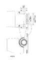
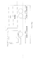
- FIG. 1 is an explanatory diagram of a region to be inspected corresponding to region A in Embodiment 1 of the present invention.
- FIG. 1 shows a side view including a front tire portion and a front view, and illustrates each surface corresponding to A1 to A4 and the shape of the detector.
- the tire vertical surface A1 corresponds to the vertical surface outside the front wheel tire, and by using the circular detector 11, quantitative measurement of radioactive contamination is performed.
- the tire upper surface A2 corresponds to a portion where the front tire contacts the running surface, and quantitative measurement of radioactive contamination is performed by using the semicircular detector 12.
- the upper surface A3 of the tire house and the vertical surface A4 at the back of the tire house are subjected to quantitative measurement of radioactive contamination by using the same semicircular detector 12 as that of the tire upper surface A2. As shown in FIG. 1, the semicircular detector 12 is tilted when measuring the vertical plane A4 at the back of the tire house.
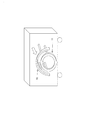
- FIG. 2 is an explanatory diagram related to the radioactive contamination inspection apparatus including the detectors 11 and 12 for performing the measurement of the region A in Embodiment 1 of the present invention.
- the detectors 11 and 12 are set on the front wheel tires by manually pushing in the arm portions as shown in FIG.
- Each of the detectors 11 and 12 needs to be arranged on the front tire so that the distance from the surface to be measured is a predetermined value or less.
- FIG. 3 is an explanatory diagram of a region to be inspected corresponding to the region B in Embodiment 1 of the present invention.
- FIG. 3 shows a side view including a rear wheel tire portion and a rear view, and illustrates each surface corresponding to B1 to B4 and the shape of the detector.
- the rear wheel tire has two trains in the traveling direction, and each of the left and right tires has two trains in the width direction. Therefore, in the measurement of the rear wheel tire, it is necessary to measure the amount of radioactive contamination for a total of eight tires.
- the tire vertical surface B1 corresponds to the vertical surface outside the rear wheel tire, and, like the front wheel, the circular detector 11 is used to quantitatively measure the radioactive contamination.
- the tire upper surface B2 corresponds to a portion where the rear tire is in contact with the running surface, and quantitative measurement of radioactive contamination is performed by using the semicircular detector 12 as in the case of the front wheel.
- the upper surface B3 of the tire house and the vertical surface B4 at the back of the tire house are used to detect radioactive contamination by using a detector 13 that can be manually changed to a U-shape. Quantitative measurements are made.
- the detector 13 is different in the shape when performing the inspection relating to the front-side rear wheel tire and the shape when performing the inspection relating to the rear-side rear wheel tire, and the portion bent into a U-shape is different. It will be deformed into individual shapes and inspected in two steps.
- two rear wheel tires that are double in the width direction can be inspected together by the detector 12. Further, the detector 13 is tilted when measuring the vertical plane B4 at the back of the tire house.
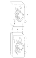
- FIG. 4 is an explanatory diagram relating to a radioactive contamination inspection apparatus provided with detectors 11, 12, and 13 for measuring the region B in Embodiment 1 of the present invention.
- the shape of the tire house is different between the front side and the rear side.
- FIG. 4A is an explanatory view of the front side
- FIG. 4B is an explanatory view of the rear side. .
- Detectors 11, 12, and 13 are set on the rear tires by manually pushing in the arm portions as shown in FIG. Each of the detectors 11, 12, and 13 needs to be disposed on the rear tire so that the distance from the surface to be measured is a predetermined value or less.
- the detector lengths of the detectors 11 and 12 are the same as those of the front wheel tire, and the detector length of the detector 13 is roughly as follows. Detector length of detector 13: 150 cm
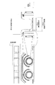
- FIG. 5 is an explanatory diagram of a region to be inspected corresponding to the region C in Embodiment 1 of the present invention.
- the tire spacing of the front wheels is 176 cm in the example shown in FIG.
- the tire interval of the rear wheels is 128 cm in the example shown in FIG. Therefore, in FIG. 5, the region C is divided into two parts, a front side with respect to the rear wheel and a rear side including the rear wheel, and the inspection is performed.
- the front side inspection of the vehicle bottom surface is performed using the detector 14 shown in FIG. 1, and the rear side inspection is performed using the detector 15 shown in FIG. .
- the detector lengths of the detectors 14 and 15 are roughly as follows, as shown in FIGS. Detector length of detector 14: 150 cm Detector length of detector 15: 100 cm
- a distance sensor is attached to each detector block, and the average distance between the detector and the bottom surface of the vehicle is calculated with the distance sensor for each fixed travel distance, and then the counting rate is calculated.
- the surface contamination area is calculated by performing the distance correction.
- the following second method may be adopted.
- the detectors 14 and 15 instead of using the detectors 14 and 15, the detectors are arranged at equal intervals on the ground at the vehicle stop position, and the count rate is measured. In this case, attach a distance sensor to each detector block, calculate the average distance between the detector and the bottom of the vehicle using the distance sensor, and then correct the count rate distance to calculate the surface contamination value. It will be.
- the above-mentioned detectors 11 to 15 ensure a detection efficiency by arranging a plurality of small and thin radiation detectors (for example, semiconductor detectors) in order to cope with inspection objects of various shapes. Can do. At the same time, the detectors 11 to 15 can be attached to a flexible base or a base formed in advance according to the shape of the object to be inspected. Can be efficiently inspected.
- small and thin radiation detectors for example, semiconductor detectors
- the first embodiment by using a thin radiation detector that can be deformed according to the shape of the inspection object, it is possible to efficiently inspect a narrow part or an object having a complicated shape.
- a radioactive contamination inspection device can be obtained.
- Embodiment 2 FIG. The first embodiment has been described on the assumption that the detector is manually set. On the other hand, in this Embodiment 2, the radioactive contamination inspection apparatus provided with the control mechanism which pinpoints the insertion position of a detector is demonstrated.
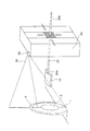
- FIG. 6 is a diagram showing the configuration of the radioactive contamination inspection apparatus according to Embodiment 2 of the present invention.
- the radioactive contamination inspection apparatus according to the second embodiment includes a detector unit 10, an arm 20, a laser distance meter 30, and a drive control device 40.
- the drive control device 40 includes a signal processing unit 41, a drive control unit 42, and a measurement unit 43.
- the detector unit 10 is a detector for quantitatively measuring the amount of radioactive contamination to be inspected.
- the detectors 11 to 15 in the first embodiment correspond to the detector unit 10.
- the detector unit 10 is attached to one end 20a of the arm 20.
- the arm 20 is attached such that the other end 20 b penetrates the drive control device 40.
- the laser distance meter 30 is a sensor that is attached to the upper part of the drive control device 40 and measures the shape of the measurement target.
- FIG. 6 shows a state in which a laser 31 is irradiated from the laser distance meter 30 toward the tire 1, the foil 2, and the tire house 3 that are measurement targets.
- the signal processing unit 41 in the drive control device 40 has a function of reconfiguring the 3D shape to be measured based on the measurement result of the laser distance meter 30.
- the drive control unit 42 in the drive control device 40 drives the positions of the detector unit 10 and the arm 20 in the vertical direction, the horizontal direction, and the depth direction of the measurement target based on the reconfigured 3D shape of the measurement target. It has a controllable configuration and functions.
- the measurement unit 43 has a function of processing a signal from the detector unit 10 and quantitatively evaluating the radiation dose.
- the signal processing unit 41 determines the positions of the tire and the tire house based on the data of the laser distance meter 30, and the drive control unit 42 Then, the measurement is performed by inserting the detector unit 10 into a desired region.
- the means for measuring the distance to the surface to be measured is not limited to the laser distance meter 30, and any means that can measure the distance to the surface to be measured with necessary accuracy, such as a stereo camera, a contact sensor, or an ultrasonic sensor. Any of these may be used.
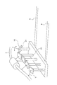
- FIG. 7 is a diagram showing another configuration of the radioactive contamination inspection apparatus according to Embodiment 2 of the present invention.
- FIG. 7 shows a case where the measurement target is the lower part of the vehicle body (that is, the region C described in the first embodiment).
- the lower part of the vehicle body is not a flat surface, and there is a measurement object having a complicated shape such as an exhaust pipe 4, for example. Therefore, when the position of the detector unit 10 is fixed, the detection sensitivity varies.
- the arm 20 that supports the detector unit 10 is movable so that the distance L from the measurement target to the detector unit 10 is constant. Variations in sensitivity are suppressed.
- the shape of the lower part of the vehicle body is a 3D shape reconstructed as in the case of FIG.
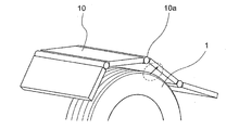
- FIG. 8 is a diagram illustrating a configuration example of the detector unit 10 according to the second embodiment of the present invention.
- the detector unit 10 adopts a structure in which the detector unit 10 is held using a hinge 10 a that can swing with respect to the arm 20.
- the detector unit 10 can be inclined obliquely toward the tire surface or the ground, and measurement according to the shape of the lower part of the vehicle body is possible.
- FIG. 7 shows a case where the drive control device 40 to which a plurality of detector units 10 are attached moves on the rail 5 to scan the lower part of the vehicle body.
- the drive control device 40 having the detector unit 10 by fixing the drive control device 40 having the detector unit 10 and passing the vehicle over the drive control device 40 having the detector unit 10 by using an external force such as self-propelled or towing, As in FIG. 7, it is possible to scan the lower part of the vehicle body.
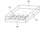
- FIG. 9 is a diagram illustrating a configuration example of the detector unit 10 used in Embodiment 2 of the present invention.
- the detector unit 10 can be a semiconductor array 100 that is a surface detector by arranging the semiconductor elements 101 in an array.
- the semiconductor elements 101 are arranged on a circuit board 102 and covered with an electromagnetic shield housing 103. Then, depending on the number of semiconductor elements 101, for example, a sensitive surface with a size of about 10 cm ⁇ 10 cm can be formed. Further, if the number of semiconductor elements 101 is further increased, a larger sensitive surface can be formed.
- the size of the sensitive surface is the extent to which the variation in distance from the measurement target surface does not affect the detection sensitivity with respect to the assumed shape of the measurement target, for example, in the case of a tire house, with respect to the curvature of the tire. What is necessary is just to determine the size of a sensitive surface.
- each semiconductor element 101 can be connected to an individual preamplifier. It is also possible to connect a plurality of semiconductor elements 101 together to one preamplifier. When a plurality of semiconductor elements 101 are used, if they are simply connected in parallel, the direct current component of the dark current is added, increasing noise.
- the semiconductor element 101 not only a silicon diode but also a compound semiconductor such as CdTe can be used. Further, the semiconductor element 101 may have either an ohmic junction or a Schottky barrier junction. Further, the thickness of the semiconductor element 101 is determined by the air dose at the place where the measurement is performed and the energy of the radiation to be measured.
- FIG. 10 is a diagram showing the relationship between the depth from the incident surface and the reflectance when the measurement target is radioactive cesium in the second embodiment of the present invention.
- the detection sensitivity can be optimized by selecting the thickness of the semiconductor according to the energy of the radiation to be measured.
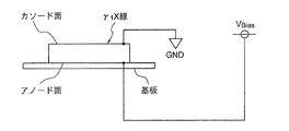
- FIG. 11 is a circuit diagram in the case where CdTe is employed as the semiconductor element 101 in the second embodiment of the present invention.
- the semiconductor element 101 such as CdTe is greatly different in the mobility of carriers (electrons and holes) generated by interaction with radiation.
- carriers electron and holes
- radiation is incident from the cathode surface, which is the cathode, as shown in FIG. 11 so that the holes can easily reach the cathode.
- the pulse output from the detector unit 10 is input to the signal processing unit 41 at the subsequent stage. Then, the signal processing unit 41 selectively counts only the radiation in the energy region to be measured.
- the energy region can be selected by using an energy window that can select only pulses having a pulse height in a predetermined range, or by using a filter based on the difference in pulse waveform.
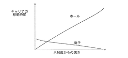
- FIG. 12 is a diagram showing an example of the relationship between the carrier generation position (depth from the incident surface) and the movement time until the carrier reaches the electrode in the second embodiment of the present invention. As shown in FIG. 12, the time for holes to reach the cathode when carriers are generated near the anode is significantly longer than the time for electrons to reach the anode when carriers are generated near the cathode.
- the characteristic X-ray of 32 keV reacts mostly in the vicinity of the cathode, so that the arrival time of both electrons and holes to the electrode is short.
- the 662 keV ⁇ -ray reacts even at a considerably deep position near the anode, so that the time for the holes to reach the electrode is particularly long.
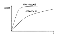
- FIG. 13 is a diagram illustrating the characteristics of the output pulse from the semiconductor element 101 according to the second embodiment of the present invention.
- the vertical axis represents the pulse peak value indicating the X-ray energy
- the horizontal axis represents time. .
- the rise time of the 662 keV ⁇ -ray tends to be slower than the 32 keV characteristic X-ray of the output pulse from the semiconductor element 101 when detecting radiation. That is, it becomes a slow pulse.
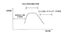
- FIG. 14 is a diagram showing the frequency characteristics of the bandpass filter according to the second embodiment of the present invention.
- FIG. 15 is a diagram showing an energy region of the semiconductor element 101 after passing through the band-pass filter in the second embodiment of the present invention.
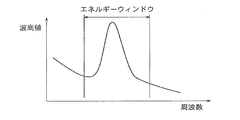
- FIG. 16 is a diagram showing a general energy window. 14 to 16, the vertical axis represents the pulse peak value indicating the X-ray energy, and the horizontal axis represents the frequency.
- the frequency characteristic of the amplifier circuit in the subsequent stage can be adjusted to the frequency band corresponding to the energy region of the characteristic X-ray of 32 keV using a band pass filter.
- the sensitivity in the energy region other than the peak of the 32 keV characteristic X-ray can be reduced.
- the signal processing unit 41 selectively counts only the radiation in the energy region to be measured, and passes the coefficient value to the measurement unit.
- the measurement unit 43 calculates the radioactivity concentration on the measurement target surface from the detection sensitivity determined by the distance between the detector unit 10 and the measurement target surface and the background count rate based on the count value of only the radiation in the energy region of the measurement target. Is calculated.
- the detection sensitivity is obtained by performing physical calculation, obtaining the sensitivity at a predetermined range of distance in advance, and storing it in the measurement unit 43 as a data table.
- the background can be measured before measurement of the measurement target, and can be obtained by calculation from the air dose rate.
- the measurement unit 43 can generate an alarm if the reference value of the radioactivity concentration (surface contamination density) is input and the radioactivity concentration on the measurement target surface is equal to or higher than the reference value.
- the measuring unit 43 can also record the contaminated position and display it on the display unit.
- the thin detector unit can be inserted at an appropriate position based on the 3D shape of the measurement object reconfigured based on the measurement result of the distance to the measurement object. It has. As a result, it is possible to efficiently inspect a narrow part or an object having a complicated shape.
- Embodiment 3 differs from the second embodiment only in that radiation is detected by using a scintillator instead of using a semiconductor element sensitive to radiation as the detector unit 10.
- the scintillator may be an organic scintillator such as a plastic scintillator, for example, and may be an inorganic scintillator such as sodium iodide or cesium iodide.
- the incident window is made thin enough to allow transmission of ⁇ rays and ⁇ rays, thereby directly measuring ⁇ rays and ⁇ rays emitted by radioactive substances adhering to the measurement target surface. Is possible.
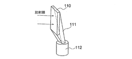
- FIG. 17 is a diagram showing a configuration example when the scintillator 110 is used as the detector unit 10 in the third embodiment of the present invention.
- the scintillator 110 is used as the detector unit 10
- scintillation light generated by detecting radiation is detected by the light receiving element 112
- a light guide 111 that collects the scintillation light is necessary.
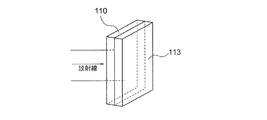
- FIG. 18 is a diagram showing another configuration example when the scintillator 110 is used as the detector unit 10 in the third embodiment of the present invention.
- a thin plate-like light receiving element 113 such as a photodiode array is optically coupled to the plate-like scintillator 110, so that the vehicle tire
- the detector unit 10 can be inserted into a narrow gap such as the house 3.
- Embodiment 4 FIG.
- the fourth embodiment is different from the third embodiment only in that the detector unit 10 is composed of a flexible scintillator. Since the detector unit itself bends, it is not necessary to connect a plurality of detector units 10. As a result, it is possible to match the detector unit itself to the shape of the surface to be measured.
- a flexible light guide such as a jelly-like one or oil. Even when the light guide is not flexible, the scintillator and the light guide are optically coupled with a flexible material, so that the light collecting efficiency of the scintillation light can be adjusted to a complicated shape without decreasing. . By this method, the variation in distance can be further reduced.
- the case where the physical quantity to be measured is the surface contamination density has been described.
- the radioactivity concentration (Bq / kg) including the inside of the measurement object by using a semiconductor element or scintillator as the detector unit 10.
- the detection sensitivity in this case is obtained by performing a physical calculation considering not only the geometric shape and the distance to the detector, but also the size and density of the measurement object. Further, the internal radioactivity concentration can also be obtained by using a radiation source simulating the measurement target.
- the radioactive substance to be measured is radioactive cesium
- the contamination state of the surface of the measurement object can be detected with high accuracy by measuring characteristic X-rays.
- characteristic X-rays it is not necessary to use a shielding structure that is required when detecting ⁇ -rays. Therefore, by specializing in the detection of characteristic X-rays, radioactive contamination on the surface of the transport vehicle can be detected with high accuracy with a simple structure.
Landscapes
- Physics & Mathematics (AREA)
- General Physics & Mathematics (AREA)
- Health & Medical Sciences (AREA)
- Life Sciences & Earth Sciences (AREA)
- High Energy & Nuclear Physics (AREA)
- Molecular Biology (AREA)
- Spectroscopy & Molecular Physics (AREA)
- Electromagnetism (AREA)
- Engineering & Computer Science (AREA)
- Radar, Positioning & Navigation (AREA)
- Remote Sensing (AREA)
- Measurement Of Radiation (AREA)
Priority Applications (2)
| Application Number | Priority Date | Filing Date | Title |
|---|---|---|---|
| US16/087,867 US20210181360A1 (en) | 2016-03-25 | 2016-06-27 | Radioactive contamination inspection device |
| EP16895462.6A EP3435119A4 (en) | 2016-03-25 | 2016-06-27 | DEVICE FOR TESTING RADIOACTIVE CONTAMINATION |
Applications Claiming Priority (2)
| Application Number | Priority Date | Filing Date | Title |
|---|---|---|---|
| JP2016-061907 | 2016-03-25 | ||
| JP2016061907A JP6301386B2 (ja) | 2016-03-25 | 2016-03-25 | 放射能汚染検査装置 |
Publications (1)
| Publication Number | Publication Date |
|---|---|
| WO2017163437A1 true WO2017163437A1 (ja) | 2017-09-28 |
Family
ID=59900988
Family Applications (1)
| Application Number | Title | Priority Date | Filing Date |
|---|---|---|---|
| PCT/JP2016/068963 Ceased WO2017163437A1 (ja) | 2016-03-25 | 2016-06-27 | 放射能汚染検査装置 |
Country Status (4)
| Country | Link |
|---|---|
| US (1) | US20210181360A1 (enExample) |
| EP (1) | EP3435119A4 (enExample) |
| JP (1) | JP6301386B2 (enExample) |
| WO (1) | WO2017163437A1 (enExample) |
Families Citing this family (5)
| Publication number | Priority date | Publication date | Assignee | Title |
|---|---|---|---|---|
| JP7079666B2 (ja) * | 2018-05-31 | 2022-06-02 | 三菱重工業株式会社 | 放射能濃度表示装置、放射能濃度算出装置、放射能濃度表示方法及び放射能濃度算出方法 |
| JP2020159870A (ja) * | 2019-03-27 | 2020-10-01 | 三菱電機プラントエンジニアリング株式会社 | タイヤハウス汚染自動検査方法 |
| JP2021038970A (ja) * | 2019-09-02 | 2021-03-11 | 三菱電機プラントエンジニアリング株式会社 | タイヤハウス汚染検査装置 |
| JP7183140B2 (ja) * | 2019-11-19 | 2022-12-05 | 三菱電機株式会社 | 放射線検出器 |
| JP7498205B2 (ja) * | 2022-02-18 | 2024-06-11 | 三菱電機プラントエンジニアリング株式会社 | 放射能汚染測定装置 |
Citations (10)
| Publication number | Priority date | Publication date | Assignee | Title |
|---|---|---|---|---|
| JPS54988B1 (enExample) | 1969-06-20 | 1979-01-18 | ||
| JPH0784054A (ja) * | 1993-09-16 | 1995-03-31 | Toshiba Corp | 放射線検出器および放射線測定装置 |
| JPH09243752A (ja) | 1996-03-07 | 1997-09-19 | Toshiba Corp | 光ファイバ型大面積放射線モニタ |
| JP2002350552A (ja) * | 2001-05-28 | 2002-12-04 | Mitsubishi Electric Corp | 放射線検出装置 |
| JP2005172771A (ja) | 2003-12-15 | 2005-06-30 | Nuclear Fuel Ind Ltd | α・β線検出装置及びα・β線検出方法 |
| JP2005195459A (ja) * | 2004-01-07 | 2005-07-21 | Toshiba Corp | 物品搬出モニタ装置 |
| JP2014126555A (ja) * | 2012-12-27 | 2014-07-07 | Canon Electronics Inc | 放射線量測定装置 |
| JP5669782B2 (ja) | 2012-03-29 | 2015-02-18 | 三菱電機株式会社 | 放射能検査装置 |
| JP2015180872A (ja) | 2014-03-05 | 2015-10-15 | エヌ・エム・ピイビジネスサポート株式会社 | 放射能測定装置および放射能測定方法 |
| WO2015198708A1 (ja) * | 2014-06-24 | 2015-12-30 | 日立Geニュークリア・エナジー株式会社 | 総合情報管理システム |
Family Cites Families (3)
| Publication number | Priority date | Publication date | Assignee | Title |
|---|---|---|---|---|
| JP4697353B2 (ja) * | 2009-04-28 | 2011-06-08 | 富士電機システムズ株式会社 | 物品搬出モニタ |
| US8908831B2 (en) * | 2011-02-08 | 2014-12-09 | Rapiscan Systems, Inc. | Covert surveillance using multi-modality sensing |
| JP5950015B2 (ja) * | 2015-11-16 | 2016-07-13 | 富士電機株式会社 | 放射線モニタ |
-
2016
- 2016-03-25 JP JP2016061907A patent/JP6301386B2/ja active Active
- 2016-06-27 EP EP16895462.6A patent/EP3435119A4/en not_active Withdrawn
- 2016-06-27 WO PCT/JP2016/068963 patent/WO2017163437A1/ja not_active Ceased
- 2016-06-27 US US16/087,867 patent/US20210181360A1/en not_active Abandoned
Patent Citations (10)
| Publication number | Priority date | Publication date | Assignee | Title |
|---|---|---|---|---|
| JPS54988B1 (enExample) | 1969-06-20 | 1979-01-18 | ||
| JPH0784054A (ja) * | 1993-09-16 | 1995-03-31 | Toshiba Corp | 放射線検出器および放射線測定装置 |
| JPH09243752A (ja) | 1996-03-07 | 1997-09-19 | Toshiba Corp | 光ファイバ型大面積放射線モニタ |
| JP2002350552A (ja) * | 2001-05-28 | 2002-12-04 | Mitsubishi Electric Corp | 放射線検出装置 |
| JP2005172771A (ja) | 2003-12-15 | 2005-06-30 | Nuclear Fuel Ind Ltd | α・β線検出装置及びα・β線検出方法 |
| JP2005195459A (ja) * | 2004-01-07 | 2005-07-21 | Toshiba Corp | 物品搬出モニタ装置 |
| JP5669782B2 (ja) | 2012-03-29 | 2015-02-18 | 三菱電機株式会社 | 放射能検査装置 |
| JP2014126555A (ja) * | 2012-12-27 | 2014-07-07 | Canon Electronics Inc | 放射線量測定装置 |
| JP2015180872A (ja) | 2014-03-05 | 2015-10-15 | エヌ・エム・ピイビジネスサポート株式会社 | 放射能測定装置および放射能測定方法 |
| WO2015198708A1 (ja) * | 2014-06-24 | 2015-12-30 | 日立Geニュークリア・エナジー株式会社 | 総合情報管理システム |
Non-Patent Citations (1)
| Title |
|---|
| See also references of EP3435119A4 |
Also Published As
| Publication number | Publication date |
|---|---|
| JP6301386B2 (ja) | 2018-03-28 |
| EP3435119A4 (en) | 2019-11-13 |
| EP3435119A9 (en) | 2019-08-21 |
| US20210181360A1 (en) | 2021-06-17 |
| JP2017173239A (ja) | 2017-09-28 |
| EP3435119A1 (en) | 2019-01-30 |
Similar Documents
| Publication | Publication Date | Title |
|---|---|---|
| JP6301386B2 (ja) | 放射能汚染検査装置 | |
| US8084748B2 (en) | Radioactive material detecting and identifying device and method | |
| EP2994776B1 (en) | Apparatus and method for the evaluation of gamma radiation events | |
| US9018586B2 (en) | Apparatuses for large area radiation detection and related method | |
| US8274056B2 (en) | Method, apparatus and system for low-energy beta particle detection | |
| JP4462429B2 (ja) | 放射線モニタ | |
| JP2015501435A (ja) | スキャン方法及び装置 | |
| EP3306352A1 (en) | Radioactive contamination inspection device | |
| JP6524484B2 (ja) | 放射線計測方法及び放射線計測装置 | |
| JPH11352233A (ja) | 核医学診断装置 | |
| JP3616036B2 (ja) | 物品放射能検出装置および物品放射能検出システム | |
| US11262462B2 (en) | Detection method and detector apparatus for correcting count rate for dead time | |
| JPH08220029A (ja) | 放射性汚染物質用非破壊検査装置と検査方法 | |
| AU2014372384B2 (en) | Radiation measurement apparatus and method | |
| JP4601838B2 (ja) | 燃焼度評価方法および装置 | |
| CN116519726B (zh) | 一种用于薄膜样品表征的正电子湮没寿命高效测量系统及方法 | |
| JP5450356B2 (ja) | 放射線検出方法 | |
| JPH01152390A (ja) | 高速中性子検出器 | |
| JP6878220B2 (ja) | 放射線測定装置及び放射線測定方法 | |
| JP2008122088A (ja) | 放射能測定装置 | |
| JP6818579B2 (ja) | 土壌放射能汚染検査装置 | |
| JP6139391B2 (ja) | 放射能検査装置及び方法 | |
| KR102382482B1 (ko) | 방사선의 검출을 이용한 검사 장치 | |
| NL2025411B1 (en) | Radiation monitoring device and inspection system. | |
| JP2007114145A (ja) | 形状可変型放射線検出器 |
Legal Events
| Date | Code | Title | Description |
|---|---|---|---|
| NENP | Non-entry into the national phase |
Ref country code: DE |
|
| WWE | Wipo information: entry into national phase |
Ref document number: 2016895462 Country of ref document: EP |
|
| ENP | Entry into the national phase |
Ref document number: 2016895462 Country of ref document: EP Effective date: 20181025 |
|
| 121 | Ep: the epo has been informed by wipo that ep was designated in this application |
Ref document number: 16895462 Country of ref document: EP Kind code of ref document: A1 |