WO2017159545A1 - カメラ - Google Patents
カメラ Download PDFInfo
- Publication number
- WO2017159545A1 WO2017159545A1 PCT/JP2017/009576 JP2017009576W WO2017159545A1 WO 2017159545 A1 WO2017159545 A1 WO 2017159545A1 JP 2017009576 W JP2017009576 W JP 2017009576W WO 2017159545 A1 WO2017159545 A1 WO 2017159545A1
- Authority
- WO
- WIPO (PCT)
- Prior art keywords
- dial
- display
- image
- brightness
- displayed
- Prior art date
- Legal status (The legal status is an assumption and is not a legal conclusion. Google has not performed a legal analysis and makes no representation as to the accuracy of the status listed.)
- Ceased
Links
Images










Classifications
-
- G—PHYSICS
- G03—PHOTOGRAPHY; CINEMATOGRAPHY; ANALOGOUS TECHNIQUES USING WAVES OTHER THAN OPTICAL WAVES; ELECTROGRAPHY; HOLOGRAPHY
- G03B—APPARATUS OR ARRANGEMENTS FOR TAKING PHOTOGRAPHS OR FOR PROJECTING OR VIEWING THEM; APPARATUS OR ARRANGEMENTS EMPLOYING ANALOGOUS TECHNIQUES USING WAVES OTHER THAN OPTICAL WAVES; ACCESSORIES THEREFOR
- G03B17/00—Details of cameras or camera bodies; Accessories therefor
- G03B17/02—Bodies
-
- H—ELECTRICITY
- H04—ELECTRIC COMMUNICATION TECHNIQUE
- H04N—PICTORIAL COMMUNICATION, e.g. TELEVISION
- H04N23/00—Cameras or camera modules comprising electronic image sensors; Control thereof
- H04N23/70—Circuitry for compensating brightness variation in the scene
- H04N23/71—Circuitry for evaluating the brightness variation
-
- G—PHYSICS
- G02—OPTICS
- G02F—OPTICAL DEVICES OR ARRANGEMENTS FOR THE CONTROL OF LIGHT BY MODIFICATION OF THE OPTICAL PROPERTIES OF THE MEDIA OF THE ELEMENTS INVOLVED THEREIN; NON-LINEAR OPTICS; FREQUENCY-CHANGING OF LIGHT; OPTICAL LOGIC ELEMENTS; OPTICAL ANALOGUE/DIGITAL CONVERTERS
- G02F1/00—Devices or arrangements for the control of the intensity, colour, phase, polarisation or direction of light arriving from an independent light source, e.g. switching, gating or modulating; Non-linear optics
- G02F1/01—Devices or arrangements for the control of the intensity, colour, phase, polarisation or direction of light arriving from an independent light source, e.g. switching, gating or modulating; Non-linear optics for the control of the intensity, phase, polarisation or colour
- G02F1/13—Devices or arrangements for the control of the intensity, colour, phase, polarisation or direction of light arriving from an independent light source, e.g. switching, gating or modulating; Non-linear optics for the control of the intensity, phase, polarisation or colour based on liquid crystals, e.g. single liquid crystal display cells
- G02F1/1313—Devices or arrangements for the control of the intensity, colour, phase, polarisation or direction of light arriving from an independent light source, e.g. switching, gating or modulating; Non-linear optics for the control of the intensity, phase, polarisation or colour based on liquid crystals, e.g. single liquid crystal display cells specially adapted for a particular application
-
- G—PHYSICS
- G03—PHOTOGRAPHY; CINEMATOGRAPHY; ANALOGOUS TECHNIQUES USING WAVES OTHER THAN OPTICAL WAVES; ELECTROGRAPHY; HOLOGRAPHY
- G03B—APPARATUS OR ARRANGEMENTS FOR TAKING PHOTOGRAPHS OR FOR PROJECTING OR VIEWING THEM; APPARATUS OR ARRANGEMENTS EMPLOYING ANALOGOUS TECHNIQUES USING WAVES OTHER THAN OPTICAL WAVES; ACCESSORIES THEREFOR
- G03B13/00—Viewfinders; Focusing aids for cameras; Means for focusing for cameras; Autofocus systems for cameras
- G03B13/02—Viewfinders
- G03B13/06—Viewfinders with lenses with or without reflectors
- G03B13/08—Viewfinders with lenses with or without reflectors with reflected image of frame
-
- G—PHYSICS
- G03—PHOTOGRAPHY; CINEMATOGRAPHY; ANALOGOUS TECHNIQUES USING WAVES OTHER THAN OPTICAL WAVES; ELECTROGRAPHY; HOLOGRAPHY
- G03B—APPARATUS OR ARRANGEMENTS FOR TAKING PHOTOGRAPHS OR FOR PROJECTING OR VIEWING THEM; APPARATUS OR ARRANGEMENTS EMPLOYING ANALOGOUS TECHNIQUES USING WAVES OTHER THAN OPTICAL WAVES; ACCESSORIES THEREFOR
- G03B13/00—Viewfinders; Focusing aids for cameras; Means for focusing for cameras; Autofocus systems for cameras
- G03B13/02—Viewfinders
- G03B13/10—Viewfinders adjusting viewfinders field
-
- G—PHYSICS
- G03—PHOTOGRAPHY; CINEMATOGRAPHY; ANALOGOUS TECHNIQUES USING WAVES OTHER THAN OPTICAL WAVES; ELECTROGRAPHY; HOLOGRAPHY
- G03B—APPARATUS OR ARRANGEMENTS FOR TAKING PHOTOGRAPHS OR FOR PROJECTING OR VIEWING THEM; APPARATUS OR ARRANGEMENTS EMPLOYING ANALOGOUS TECHNIQUES USING WAVES OTHER THAN OPTICAL WAVES; ACCESSORIES THEREFOR
- G03B17/00—Details of cameras or camera bodies; Accessories therefor
- G03B17/18—Signals indicating condition of a camera member or suitability of light
-
- H—ELECTRICITY
- H04—ELECTRIC COMMUNICATION TECHNIQUE
- H04N—PICTORIAL COMMUNICATION, e.g. TELEVISION
- H04N21/00—Selective content distribution, e.g. interactive television or video on demand [VOD]
- H04N21/40—Client devices specifically adapted for the reception of or interaction with content, e.g. set-top-box [STB]; Operations thereof
- H04N21/47—End-user applications
-
- H—ELECTRICITY
- H04—ELECTRIC COMMUNICATION TECHNIQUE
- H04N—PICTORIAL COMMUNICATION, e.g. TELEVISION
- H04N23/00—Cameras or camera modules comprising electronic image sensors; Control thereof
- H04N23/50—Constructional details
-
- H—ELECTRICITY
- H04—ELECTRIC COMMUNICATION TECHNIQUE
- H04N—PICTORIAL COMMUNICATION, e.g. TELEVISION
- H04N23/00—Cameras or camera modules comprising electronic image sensors; Control thereof
- H04N23/50—Constructional details
- H04N23/51—Housings
-
- H—ELECTRICITY
- H04—ELECTRIC COMMUNICATION TECHNIQUE
- H04N—PICTORIAL COMMUNICATION, e.g. TELEVISION
- H04N23/00—Cameras or camera modules comprising electronic image sensors; Control thereof
- H04N23/60—Control of cameras or camera modules
- H04N23/63—Control of cameras or camera modules by using electronic viewfinders
-
- H—ELECTRICITY
- H04—ELECTRIC COMMUNICATION TECHNIQUE
- H04N—PICTORIAL COMMUNICATION, e.g. TELEVISION
- H04N23/00—Cameras or camera modules comprising electronic image sensors; Control thereof
- H04N23/70—Circuitry for compensating brightness variation in the scene
- H04N23/74—Circuitry for compensating brightness variation in the scene by influencing the scene brightness using illuminating means
-
- H—ELECTRICITY
- H04—ELECTRIC COMMUNICATION TECHNIQUE
- H04N—PICTORIAL COMMUNICATION, e.g. TELEVISION
- H04N21/00—Selective content distribution, e.g. interactive television or video on demand [VOD]
- H04N21/40—Client devices specifically adapted for the reception of or interaction with content, e.g. set-top-box [STB]; Operations thereof
- H04N21/47—End-user applications
- H04N21/485—End-user interface for client configuration
Definitions
- the present invention relates to a camera, and more particularly to a camera provided with a rotary dial on a camera body.
- the rotary dial has a drawback that it is difficult to operate in a dark place because it is operated while looking at the dial.
- Patent Document 1 proposes that a dial having a lock function incorporates illumination and that the illumination in the dial is turned on in conjunction with the unlocking operation of the dial. Patent Document 1 proposes that an image of a dial is displayed on an image display monitor provided on the back of the camera body in conjunction with the unlocking operation of the dial.
- Patent Document 2 proposes that an image of a dial is displayed on an image display monitor provided on the back of the camera body in conjunction with the operation of an illumination button.
- Patent Document 3 proposes detecting contact with a dial and displaying an image of the dial on an image display monitor provided on the back of the camera body.
- the present invention has been made in view of such circumstances, and an object thereof is to provide a camera with good operability without depending on the brightness of the surrounding environment.
- a plurality of selectable items are displayed along the rotation direction, a rotary dial that selects an item to be set according to an index, a brightness detection unit that detects the brightness of the surrounding environment, a display unit, A display control unit that controls display of the display unit, and the display control unit displays the setting content of the camera on the display unit, and when the brightness detected by the brightness detection unit is less than the specified brightness A camera that displays an image representing a dial setting state on a display unit.
- the setting content of the camera is displayed on the display unit in a situation where the surrounding environment is bright.
- an image representing the dial setting state is displayed on the display unit.
- the dial can be appropriately operated even in a dark environment.
- an image representing the dial setting state is displayed on the display unit only under dark conditions, the operability of the camera under bright conditions is not impaired.
- the display on the display unit changes according to the dial rotation operation. That is, the image representing the dial setting state changes according to the dial rotation operation.
- the display is linked to the operation of the dial, and a desired item can be easily selected.
- a contact detection unit that detects contact with the dial is further provided, and the display control unit detects that the brightness detected by the brightness detection unit is equal to or lower than a specified brightness, and the contact detection unit contacts the dial.
- the camera according to (1) wherein an image representing a dial setting state is displayed on the display unit when the is detected.
- an image indicating the dial setting state is not displayed.
- an image indicating the dial setting state is displayed on the display unit. Is done. Thereby, an image representing the dial setting state can be displayed on the display unit only when it is really necessary, and the operability of the entire camera can be further improved.
- the display control unit displays an image indicating the setting state of the dial on the display unit when the brightness detected by the brightness detection unit is equal to or lower than the predetermined brightness and the dial is rotated.
- the camera according to (1) wherein an image representing a dial setting state is changed according to a dial rotation operation.
- an image indicating the dial setting state is not displayed.
- an image indicating the dial setting state is displayed on the display unit.
- the dial image is displayed on the display unit as an image representing the dial setting state.
- the display control unit displays an image image obtained by cutting out a part of the dial on the display unit when the dial image is displayed on the display unit as an image representing the setting state of the dial. Camera.
- the image image obtained by cutting out a part of the dial is displayed as an image representing the setting state of the dial.
- the display control unit displays an image representing the dial setting state on the display unit
- the display setting unit reduces the setting content of the camera and displays it on the display unit. Any one of (1) to (6) above camera.
- the image representing the dial setting state and the camera setting content are displayed on the display unit.
- the setting contents of the camera are displayed smaller than normal.
- the normal time means when an image representing the dial setting state is not displayed, and is when the surrounding environment is bright.
- the dial is provided on the top surface of the camera body. Dial settings can be easily confirmed.
- the dial and the display unit are provided on the top surface of the camera body. Therefore, when the image showing the setting state of the dial is displayed on the display unit, the relationship between the dial and the display on the display unit can be clarified, and the operability can be further improved. Further, since the dial and the display unit are arranged on the same surface, the dial can be easily operated while viewing the display unit. In order to enable a more intuitive operation, it is preferable to arrange the display unit and the dial close to each other.
- the display unit is configured by a reflective liquid crystal display provided with illumination.
- a reflective liquid crystal display provided with illumination.
- the display unit is configured by electronic paper provided with illumination. Therefore, regarding the display of a display part, favorable visibility can be ensured even in an environment where the surrounding is bright. Even when the camera is turned off, the display on the display unit can be confirmed.
- the display unit is configured by a memory liquid crystal display provided with illumination.
- a memory liquid crystal display provided with illumination.
- An illumination control unit that controls illumination is further provided, and the illumination control unit turns on the illumination when the brightness detected by the brightness detection unit is less than or equal to the specified brightness. ) Any one of the cameras.
- the illumination when the surrounding environment becomes dark, the illumination is turned on. Thereby, favorable visibility can be secured even in a dark environment.
- the brightness of the surrounding environment is detected based on the photographing light.
- the photographing light is light that enters the camera for photographing, and is light that enters the camera through a lens.
- the brightness of the surrounding environment can be easily detected.
- the brightness of the top surface can be appropriately detected by detecting the brightness of the surrounding environment based on the photographing light. That is, since the brightness of the top surface substantially matches the brightness of the photographing light, the brightness of the top surface can be detected by detecting the brightness of the surrounding environment based on the photographing light.
- the display of a display part can be controlled appropriately according to the brightness of surrounding environment.
- At least one of shutter speed, aperture value, and sensitivity is displayed as the setting content of the camera.
- a camera with good operability can be provided without depending on the brightness of the surrounding environment.
- FIG. 1 Front view showing the external structure of the digital camera Rear view showing external configuration of digital camera Top view showing the external structure of the digital camera Left side view showing the external structure of the digital camera Top view of a digital camera equipped with a lens
- FIG. 1 An enlarged plan view around the shutter speed dial Block diagram showing schematic configuration of control system of digital camera
- Functional block diagram of the display controller The flowchart which shows the procedure of the display process to a sub display by a display control part
- Functional block diagram of the display controller The flowchart which shows the procedure of the display process to a sub display by a display control part
- the figure which shows another example of the image showing the setting state of a dial The figure which shows another example of the image showing the setting state of a dial
- the figure which shows another example of the image showing the setting state of a dial The figure which shows another example of the image showing
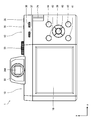
- FIG. 2 is a front view, a rear view, a plan view, and a left side view, respectively, showing the external configuration of the digital camera.
- the direction along the optical axis L is the front-rear direction
- the subject side is the front direction.
- the direction along the long side of the image sensor 50 is the horizontal direction or the left-right direction
- the direction along the short side of the image sensor 50 is the vertical direction or vertical direction.
- the digital camera 1 of the present embodiment is an interchangeable lens digital camera and a non-reflex digital camera.
- the interchangeable lens type is a digital camera that can exchange lenses.
- the non-reflex type is a digital camera without a reflex mirror for guiding incident light from a lens to an optical viewfinder. Also called mirrorless.
- FIG. 5 is a plan view of a digital camera equipped with a lens.
- the digital camera 1 of the present embodiment is used with a lens 2 attached to a camera body 10.
- the camera body 10 includes a lens mount 14, a main display 16, a sub display 18, an electronic viewfinder 20, various operation buttons, and the like.
- the camera body 10 has a rectangular box shape with a small thickness in the front-rear direction.
- the camera body 10 has an end portion on one side (left side in FIG. 1) configured as a grip portion 12.
- the grip portion 12 includes a grip 22 on the front side and a thumb rest 24 on the back side.
- the lens mount 14 is a mounting portion for the lens 2. As shown in FIG. 1, the lens mount 14 is provided in front of the camera body 10.
- the main display 16 is a large screen display for displaying images and the like.
- the main display 16 is used for displaying captured images, displaying live view images, and mainly displaying images.
- the main display 16 is used as a setting screen for performing various settings. That is, the main display 16 is also used as a GUI (GUI: Graphical User Interface).
- GUI Graphical User Interface
- the main display 16 is provided on the back surface of the camera body 10.
- the main display 16 is composed of, for example, a color LCD (LCD: Liquid Crystal Display).
- the sub display 18 is a small screen display for displaying the setting contents of the camera. As shown in FIG. 3, the sub-display 18 and the top surface of the camera body 10 are provided.
- the sub display 18 is configured by, for example, a reflective LCD (reflective liquid crystal display) with illumination.
- the electronic viewfinder 20 is provided on the top surface of the camera body 10. As shown in FIG. 2, the eyepiece 20 ⁇ / b> A of the electronic viewfinder 20 is disposed on the back surface of the camera body 10.
- the camera body 10 has operation buttons such as a shutter button 30, a power lever 31, a front command dial 32, a shutter speed dial 33, an illumination button 35, a function button 36, a first rear command dial 37, and a second rear command dial 38. , A selector button 39, a menu button 40, a cancel button 41, a playback button 42, an erase button 43, a shooting condition setting button 44, and the like.
- the shutter button 30 is a member that instructs execution of shooting.
- the shutter button 30 is composed of a two-stage switch composed of a so-called half press and a full press. When the shutter button 30 is half-pressed, photometry, distance measurement, and the like are performed, and when the shutter button 30 is fully pressed, actual photographing is performed.
- the shutter button 30 is provided on the top of the grip 22.
- the power lever 31 is a member that switches the power on and off.
- the power lever 31 is disposed coaxially with the shutter button 30 and is rotated between an on position and an off position.
- the front command dial 32 is a member that is rotated, and various functions are assigned depending on the setting status of the digital camera 1.
- the front command dial 32 can be rotated endlessly and can be pushed in.
- the pushing operation is an operation for pushing in a direction orthogonal to the rotation axis.
- the front command dial 32 has a click mechanism, and when it is rotated, a click feeling is generated at regular angular intervals.
- the front command dial 32 is provided on the grip 22, and a part of the front command dial 32 is disposed so as to be exposed on the outer surface of the grip 22.
- the user rotates the front command dial 32 by turning the part exposed from the outer surface of the grip 22 with a finger. Further, the front command dial 32 is pushed in by pushing the portion exposed from the outer surface of the grip 22 into the grip with a finger.
- the shutter speed dial 33 is a member for setting the shutter speed. As shown in FIG. 2, the shutter speed dial 33 is provided on the top surface of the camera body 10. The shutter speed dial 33 is disposed adjacent to the sub display 18.
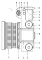
- FIG. 6 is an enlarged plan view around the shutter speed dial.
- the shutter speed dial 33 is composed of a rotary dial.
- the shutter speed dial 33 has a disk shape and is configured to be rotatable endlessly about an axis.
- the shutter speed dial 33 has a dial 33a on the top surface (upper surface).
- the dial 33a displays a plurality of selectable shutter speed values as selectable items. Selectable shutter speed values are displayed at regular intervals along the direction of rotation. In the digital camera 1 of the present embodiment, selectable shutter speed values are 1, 1/2, 1/4, 1/8, 1/15, 1/30, 1/60, 1/125, 1 / 180, 1/250, 1/500, 1/1000, 1/2000, 1/4000, 1/8000 (second) are prepared. The notation on the dial is displayed as an inverse.
- 1, 1/2, 1/4, 1/8, 1/15, 1/30, 1/60, 1/125, 1/180, 1/250, 1/500, 1/1000, 1 / 2000, 1/4000, and 1/8000 (seconds) are displayed as 1, 2, 4, 6, 15, 30, 60, 125, 180, 250, 500, 1000, 200, 4000, and 8000, respectively. Therefore, for example, when “60” on the dial is selected, the shutter speed is set to 1/60 second.
- a time shooting mode and a bulb shooting mode are prepared as items that can be selected by the shutter speed dial 33. The notation on the dial of each item is T and B. When “T” on the dial is selected, the time shooting mode is set, and when “B” is selected, the bulb shooting mode is set.
- the time shooting mode is a mode in which exposure is performed for a time arbitrarily designated by the user.
- the bulb shooting mode is a mode in which exposure is performed only while the shutter button 30 is pressed. Both are selected when it is necessary to expose for a time longer than 1 second.
- an indicator 34 for selecting the shutter speed is provided in the vicinity of the shutter speed dial 33.
- an index 34 is provided between the shutter speed dial 33 and the sub display 18 (provided at the 3 o'clock position as viewed from the shutter speed dial 33). The user selects the shutter speed by matching the notation of the desired shutter speed with the position of the index 34. For example, when 1/60 second is selected as the shutter speed, the shutter speed dial 33 is rotated so that “60” on the dial 33 a is aligned with the index 34.
- the shutter speed dial 33 has a click mechanism.
- a click feeling is generated in accordance with the pitch indicated on the dial 33a.
- the click stop position coincides with the position of the indicator 34. Therefore, when the shutter speed dial 33 is rotated in the forward direction (the clockwise direction indicated by the arrow R + in FIG. 6), the notation is incremented by one for each click.
- the shutter speed dial 33 is rotated in the reverse direction (counterclockwise direction indicated by arrow R- in FIG. 6), the notation is incremented by one for each click.
- the illumination button 35 is a member that switches on / off the illumination provided in the sub-display 18. Each time the illumination button 35 is pressed, the illumination of the sub display 18 is switched on and off.
- the illumination button 35 is provided on the top surface of the camera body 10.
- the function button 36 is assigned various functions according to the setting status of the digital camera 1.
- the function button 36 is provided on the top surface of the camera body 10.
- the function button 36 and the illumination button 35 are arranged in parallel and are arranged in the vicinity of the sub display 18.
- the first rear command dial 37 is a member to be rotated, and various functions are assigned according to the setting status of the digital camera 1.
- the first rear command dial 37 is configured to be capable of rotating endlessly and being pushed in. Further, the first rear command dial 37 has a click mechanism, and when it is rotated, a click feeling is generated at regular angular intervals.
- the first rear command dial 37 is provided on the back surface of the camera body 10, and a part of the first rear command dial 37 is disposed so as to be exposed from the back surface of the camera body 10.
- the second rear command dial 38 is a member that is rotated, and various functions are assigned according to the setting status of the digital camera 1.
- the second rear command dial 38 is configured to be able to rotate endlessly and to be pushed in. Further, the second rear command dial 38 has a click mechanism, and when it is rotated, a click feeling is generated at a constant angular interval.
- the second rear command dial 38 is provided on the back surface of the camera body 10, and a part of the second rear command dial 38 is disposed so as to be exposed from the back surface of the camera body 10.
- the first rear command dial 37 and the second rear command dial 38 are arranged in parallel on the rear surface of the camera body 10 and are arranged so as to be rotatable in the horizontal direction.
- the first rear command dial 37 and the second rear command dial 38 are arranged in parallel in the vicinity of the thumb rest 24 so that it can be operated with the thumb of the hand gripping the camera body 10.
- a part of the digital camera 1 is disposed so as to overlap the sub-display 18. That is, the first rear command dial 37 and the second rear command dial 38 are arranged so as to be hidden under the sub display 18.
- the selector button 39 is a button that can give instructions in four directions, up, down, left, and right, and is composed of four buttons arranged on the same circle. Functions corresponding to the setting status of the digital camera 1 are assigned to the buttons in each direction.
- the selector button 39 is provided on the back surface of the camera body 10.
- the menu button 40 is a button for calling a menu screen. By pressing the menu button 40, a menu screen for performing various settings is displayed on the main display 16.
- the menu button 40 also functions as a confirmation button (OK button) and is used for confirmation of selection items.
- the menu button 40 is provided on the back surface of the camera body 10.
- the cancel button 41 is a button for instructing cancellation of the operation. By pressing the cancel button 41, an instruction to cancel the selection item or the like is input.
- the cancel button 41 is provided on the back surface of the camera body 10.
- the playback button 42 is a button for instructing switching to the playback mode. By pressing the playback button 42, the mode of the digital camera 1 is switched to the playback mode. When the playback mode is set, the captured image is read from the memory card and displayed on the main display 16 for playback.
- the playback button 42 is provided on the back surface of the camera body 10.
- the delete button 43 is a button for instructing deletion of a captured image.
- the erase button 43 is provided on the back surface of the camera body 10.
- the shooting condition setting button 44 is a button for calling a shooting condition setting screen. By pressing the shooting condition setting button 44, a shooting condition setting screen is displayed on the main display 16. The shooting condition setting button 44 is provided on the back of the camera body 10.
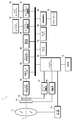
- FIG. 7 is a block diagram illustrating a schematic configuration of a control system of the digital camera.
- the digital camera 1 includes an image sensor 50, an image sensor driving unit 52, a shutter 54, a shutter driving unit 56, an analog signal processing unit 58, an image data input unit 60, a work memory 62, a data memory 64, a digital signal processing unit 66, a recording A control unit 68, a main display driving unit 70, a sub display driving unit 72, an operation unit 74, a brightness detection unit 76, a system controller 80, and the like are included.
- the image sensor 50 converts the optical image of the subject formed through the lens 2 into an electrical signal and outputs it.
- a known image sensor such as a CCD image sensor (CCD: “Charged” Coupled Device) or a CMOS image sensor (CMOS: “Complementary” Metal ”Oxide” Semiconductor) is used.
- the image sensor driving unit 52 drives the image sensor 50 in response to a command from the system controller 80.
- the shutter 54 is composed of a square-type focal plane shutter and is disposed immediately before the image sensor 50.
- the shutter drive unit 56 drives the shutter 54 in response to a command from the system controller 80.
- the analog signal processing unit 58 takes in the signal output from the image sensor 50 and performs necessary signal processing such as correlated double sampling processing and amplification processing.
- the analog signal processing unit 58 converts the analog image signal subjected to the required signal processing into a digital image signal and outputs the digital image signal.
- the image data input unit 60 takes in a digital image signal output from the analog signal processing unit 58 in response to a command from the system controller 80.
- the captured image data for one sheet is stored in the work memory 62.
- the work memory 62 is used as a working memory.
- the data memory 64 is composed of a nonvolatile memory, and stores various data necessary for control and the like.
- the digital signal processing unit 66 performs necessary signal processing such as demosaicing processing, white balance correction, gamma correction, contour correction, etc. on the image data captured in the work memory 62 to obtain luminance data (Y data) and color difference. Predetermined image data composed of data (Cr, Cb data) is generated.
- the recording control unit 68 accesses the memory card 78 in accordance with a command from the system controller 80 and reads / writes data. Image data obtained by shooting is recorded in the memory card 78.
- the main display driving unit 70 drives the main display 16 in response to a command from the system controller 80.
- the sub display driving unit 72 drives the sub display 18 in response to a command from the system controller 80.
- the operation unit 74 includes a shutter button 30, a power lever 31, a front command dial 32, a shutter speed dial 33, an illumination button 35, a function button 36, a first rear command dial 37, a second rear command dial 38, a selector button 39, A menu button 40, a cancel button 41, a playback button 42, an erase button 43, and the like are included.
- the operation unit 74 outputs a signal corresponding to the operation of each operation member to the system controller 80.
- the brightness detection unit 76 detects the brightness of the surrounding environment.
- the brightness of the surrounding environment is detected based on the photographing light. That is, the brightness of the surrounding environment is detected based on the image data obtained by shooting.
- the brightness detection unit 76 acquires image data from the digital signal processing unit 66, and detects the brightness of the surrounding environment based on the obtained image data. Specifically, the brightness of the surrounding environment is calculated based on the luminance data.
- the system controller 80 is a control unit that controls the operation of each unit of the digital camera 1.
- the system controller 80 is composed of a microcomputer. That is, the microcomputer functions as the system controller 80 by executing a predetermined control program, and functions as a control unit that controls the operation of each unit of the digital camera 1.
- the system controller 80 functions even if it functions as the control unit of the lens 2.
- the system controller 80 controls the operation of the lens 2 via the lens driving unit 2 a provided in the lens 2.
- the lens 2 includes a diaphragm, a focus lens, and the like.
- the lens driving unit 2a includes a diaphragm driving unit that drives a diaphragm, a focus lens driving unit that drives a focus lens, and the like.
- the display of the sub display 18 that is a display unit is switched based on the brightness of the surrounding environment. That is, in a situation where the surrounding environment is bright, the setting contents of the digital camera 1 are displayed on the sub display 18. On the other hand, when the surrounding environment becomes dark, an image representing the setting state of the shutter speed dial 33 is displayed on the sub display 18.
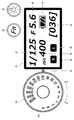
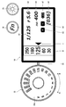
- FIG. 6 shows an example of the display on the sub display 18 when the surrounding environment is bright.
- the current setting content of the digital camera 1 is displayed on the sub display 18.
- This display is a normal display.
- the setting contents include shutter speed A1, aperture value (F value) A2, ISO sensitivity A3 (ISO: International Organization for Standardization), shootable number A4, and shooting mode.
- Information on A5, image size A6, and remaining battery charge A7 is displayed. Each information is displayed at a specified position.
- the digital camera 1 of the present embodiment is provided with a program mode, a shutter speed priority mode, an aperture priority mode, and a manual mode as shooting modes, and an icon corresponding to each mode is displayed at the shooting mode display position.
- the program mode is a mode in which the camera automatically determines the aperture value and the shutter speed so as to achieve proper exposure.
- the shutter speed priority mode is a mode in which the camera automatically determines the aperture value so that the exposure is appropriate for the shutter speed selected by the user.
- the aperture priority mode is a mode in which the camera automatically determines the shutter speed so that an appropriate exposure is obtained for the aperture value selected by the user.
- the manual mode is a mode in which the user decides the shutter speed and aperture value and shoots.
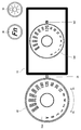
- FIG. 8 is a diagram illustrating an example of a sub-display display when the surrounding environment is dark.
- the image image Im1 of the shutter speed dial 33 is displayed on the sub display 18 together with the image image Im2 of the index 34 as an image representing the setting state of the shutter speed dial 33.
- the image image is an image imitating the appearance of the shutter speed dial 33.
- an image obtained by cutting out a part of the shutter speed dial 33 is displayed on the sub display 18 as an image image Im1.
- the selected shutter speed is enlarged and displayed so that the shutter speed selected by the shutter speed dial 33 becomes clear.
- the current settings of the digital camera 1 are displayed in the margin area. At this time, the layout is changed as necessary to reduce the display. In addition, display items are thinned out as necessary. For example, only the aperture value and ISO sensitivity are displayed.
- the image representing the setting state of the shutter speed dial 33 is displayed on the sub display 18 so that the shutter speed dial 33 can be operated even in a dark situation.
- Display control of the sub display 18 is performed by the system controller 80.
- the system controller 80 functions as the display control unit 80a of the sub display 18 by executing a predetermined control program.
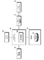
- FIG. 9 is a functional block diagram of the display control unit.
- the display control unit 80 a acquires the brightness detection result from the brightness detection unit 76. Then, the acquired brightness and the threshold value are compared. That is, it is determined whether the brightness of the surrounding environment is equal to or less than the specified brightness. When the brightness exceeds the threshold value, it is determined that the surrounding environment is bright, and the display on the sub-display 18 is set as a normal display. That is, as shown in FIG. 6, the current setting contents of the digital camera 1 are displayed on the sub display 18. On the other hand, if the brightness is less than or equal to the threshold value, it is determined that the surrounding environment is dark, and an image representing the setting state of the shutter speed dial 33 is displayed on the sub display 18.
- the data memory 64 stores image data of the image image Im1 of the shutter speed dial 33 and image data of the image image Im2 of the index 34.
- the display control unit 80a stores image data of the image image Im1 of the shutter speed dial 33 and image data of the image image Im2 of the index 34.
- Data obtained from the memory 64 and displayed on the sub-display 18 is generated.
- the sub display driving unit 72 is driven to display information on the sub display 18.
- the image representing the setting state of the shutter speed dial 33 is also changed.
- the image image Im1 of the shutter speed dial 33 is rotated in conjunction with the rotation of the shutter speed dial 33. That is, the image Im is rotated like an animation.
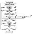
- FIG. 10 is a flowchart showing the procedure of display processing on the sub display by the display control unit.
- step S11 information on the brightness of the surrounding environment is acquired.
- Information on the brightness of the surrounding environment is acquired from the brightness detection unit 76.
- step S12 based on the acquired brightness information, it is determined whether the brightness of the surrounding environment is equal to or less than a threshold value (step S12). That is, it is determined whether the brightness of the surrounding environment is equal to or less than a certain brightness.
- the display control unit 80a sets the display of the sub display 18 to normal display (step S13). That is, the current setting information of the digital camera 1 is acquired, and the current setting contents of the digital camera 1 are displayed on the sub-display 18 in a predetermined layout as shown in FIG.
- the display control unit 80a sets the display on the sub-display 18 to the dark place display (step S14). That is, the current setting information of the digital camera 1 and the setting information of the shutter speed dial 33 are acquired, and as shown in FIG. 8, an image showing the current setting contents of the digital camera 1 and the setting state of the shutter speed dial 33 Is displayed on the sub-display 18.
- step S15 it is determined whether or not the power is turned off. If the power is turned off, the process ends. On the other hand, if the power is not turned off, the process returns to step S11 and the above processes are repeatedly executed.
- the display of the sub-display 18 is switched according to the brightness of the surrounding environment, and the setting content of the camera is displayed on the display unit in a bright situation.
- the surrounding environment becomes dark, an image representing the setting state of the shutter speed dial 33 is displayed.
- the shutter speed dial 33 can be appropriately operated even in a dark environment. Further, since an image representing the setting state of the shutter speed dial 33 is displayed only under dark conditions, the operability under bright conditions is not impaired.
- the sub display 18 is disposed adjacent to the shutter speed dial 33, and the image image Im1 of the shutter speed dial 33 is displayed in a direction close to the shutter speed dial 33, so that the relationship between the two is more clearly shown. it can.
- FIG. 11 is a flowchart showing a procedure of display processing on the sub display by the display control unit.
- step S21 information on the brightness of the surrounding environment is acquired.
- Information on the brightness of the surrounding environment is acquired from the brightness detection unit 76.
- step S22 based on the acquired brightness information, it is determined whether the brightness of the surrounding environment is equal to or less than a threshold value (step S22). That is, it is determined whether the brightness of the surrounding environment is equal to or less than a certain brightness.
- the display control unit 80a sets the display of the sub display 18 to normal display (step S27). That is, as shown in FIG. 6, the current setting contents of the digital camera 1 are displayed on the sub display 18.
- step S23 it is determined whether or not the shutter speed dial 33 has been rotated based on information from the operation unit 74 (step S23).
- the display control unit 80a sets the display on the sub display 18 to normal display (step S27). That is, the current setting information of the digital camera 1 is acquired, and the current setting contents of the digital camera 1 are displayed on the sub-display 18 in a predetermined layout as shown in FIG.
- the display control unit 80a sets the display on the sub-display 18 to the dark place display (step S24). That is, the current setting information of the digital camera 1 and the setting information of the shutter speed dial 33 are acquired, and as shown in FIG. 8, an image representing the current setting contents of the digital camera 1 and the setting state of the shutter speed dial 33 Is displayed on the sub-display 18.
- the display control unit 80a sets the display on the sub-display 18 to a dark place display during the rotation operation of the shutter speed dial 33. At this time, the display is changed in conjunction with the operation of the shutter speed dial 33.
- the display control unit 80a is linked with the rotation operation of the shutter speed dial 33 to display the image image Im. Rotate.
- the display control unit 80a determines whether or not the rotation operation of the shutter speed dial 33 has been completed (step S25). During the operation, the display on the sub-display 18 is continuously used as the display for the dark place.
- the display control unit 80a determines whether or not a predetermined time has elapsed since the operation was completed (step S26). That is, even when the operation is completed, the dark place display is continued for a certain time.
- the display control unit 80a switches the display on the sub-display 18 to the normal display (step S27).
- step S28 it is determined whether or not the power is turned off. If the power is turned off, the process ends. On the other hand, if the power is not turned off, the process returns to step S21, and the above processes are repeated.
- the display on the sub-display 18 is a dark display only when the shutter speed dial 33 is rotated. That is, even when the surrounding environment is dark, the normal display is maintained unless the shutter speed dial 33 is rotated. Thereby, the display on the sub-display 18 can be made suitable for the usage status of the digital camera 1, and the operability of the entire digital camera can be further improved.
- FIG. 12 is a functional block diagram of the display control unit.
- the shutter speed dial 33 is provided with a touch sensor 33T as a contact detection unit.
- the touch sensor 33T detects contact with the shutter speed dial 33.
- the touch sensor 33T is provided on the dial 33a of the shutter speed dial 33, for example.
- the display control unit 80 a controls the display of the sub display 18 based on information from the brightness detection unit 76 and the operation unit 74.
- FIG. 13 is a flowchart showing the procedure of display processing on the sub-display by the display control unit.
- step S31 information on the brightness of the surrounding environment is acquired.
- Information on the brightness of the surrounding environment is acquired from the brightness detection unit 76.
- step S32 based on the acquired brightness information, it is determined whether the brightness of the surrounding environment is equal to or less than a threshold value (step S32). That is, it is determined whether the brightness of the surrounding environment is equal to or less than a certain brightness.
- the display control unit 80a sets the display of the sub display 18 to normal display (step S37). That is, as shown in FIG. 6, the current setting contents of the digital camera 1 are displayed on the sub display 18.
- step S33 it is determined based on information from the operation unit 74 whether or not the shutter speed dial 33 has been touched. Specifically, it is determined whether or not the shutter speed dial 33 is touched based on the output from the touch sensor 33T.
- the display control unit 80a sets the display of the sub display 18 to the normal display (step S37). That is, the current setting information of the digital camera 1 is acquired, and the current setting contents of the digital camera 1 are displayed on the sub-display 18 in a predetermined layout as shown in FIG.
- the display control unit 80a sets the display on the sub-display 18 to the dark place display (step S34). That is, the current setting information of the digital camera 1 and the setting information of the shutter speed dial 33 are acquired, and as shown in FIG. 8, an image representing the current setting contents of the digital camera 1 and the setting state of the shutter speed dial 33 Is displayed on the sub-display 18.
- the display control unit 80a sets the display on the sub-display 18 as a dark place display while the shutter speed dial 33 is being touched. At this time, if the shutter speed dial 33 is rotated, the display is changed in conjunction with the rotation.
- the display control unit 80a determines whether or not the touch on the shutter speed dial 33 is finished (step S35). While the shutter speed dial 33 is being touched, the display control unit 80a continues to display the sub display 18 as a dark place display.
- the display control unit 80a determines whether or not a certain time has passed since the touch was finished (step S36). That is, even after the touch is finished, the dark display is continued for a certain time.
- the display control unit 80a switches the display of the sub display 18 to the normal display (step S37).
- step S38 it is determined whether or not the power is turned off. If the power is turned off, the process ends. On the other hand, if the power is not turned off, the process returns to step S31, and the above processes are repeated.
- the display on the sub-display 18 is a dark place display only when the shutter speed dial 33 is touched. That is, even when the surrounding environment is dark, the normal display is maintained unless the shutter speed dial 33 is touched. Thereby, the display on the sub-display 18 can be made suitable for the usage status of the digital camera 1, and the operability of the entire digital camera can be further improved.
- FIG. 14 is a diagram illustrating another example of an image representing a dial setting state.
- the shutter speed currently selected for the window images W + 2, W + 1, W ⁇ 0, W-1, and W-2 arranged in an arc shape and the shutter speed dial 33 are rotated in the forward direction.
- the shutter speed that can be selected sometimes and the shutter speed that can be selected when the shutter speed dial 33 is rotated in the reverse direction are displayed, and an image representing the setting state of the shutter speed dial is displayed.
- the currently selected shutter speed is displayed as an inverse number.
- the center window image W ⁇ 0 is displayed larger than the other window images.
- the center window image W ⁇ 0 is indicated by the index image I.
- window images W + 1 and W + 2 shutter speeds that can be selected when the shutter speed dial 33 is rotated in the forward direction are displayed as reciprocal numbers.
- window image W + 1 shutter speeds that can be selected when the shutter speed dial 33 is rotated one step (one click) in the forward direction are displayed as reciprocal numbers.
- window image W + 2 shutter speeds that can be selected when the shutter speed dial 33 is rotated in two steps (two clicks) in the forward direction are displayed as reciprocal numbers.
- window images W-1 and W-2 shutter speeds that can be selected when the shutter speed dial 33 is rotated in the reverse direction are displayed as reciprocal numbers.
- the shutter speeds that can be selected when the shutter speed dial 33 is rotated one step in the reverse direction are displayed as reciprocal numbers.
- window image W-2 shutter speeds that can be selected when the shutter speed dial 33 is rotated by two steps in the reverse direction are displayed as reciprocal numbers.
- the entire window images W + 2, W + 1, W ⁇ 0, W-1, and W-2 rotate clockwise, and the display is switched.
- the entire window images W + 2, W + 1, W ⁇ 0, W-1, and W-2 are rotated counterclockwise, and the display is switched.
- the operating direction of the shutter speed dial 33 with respect to the index 34 matches the direction in which the display is switched. For this reason, operation is easy. In addition, since the selected shutter speed is enlarged and displayed, the selection operation can be easily performed.
- the shutter speed up to two steps ahead is displayed.
- FIG. 15 is a diagram showing another example of an image representing a dial setting state.
- the currently selected shutter speed the shutter speed that can be selected when the shutter speed dial 33 is rotated in the forward direction
- the shutter speed dial 33 that is selected when the shutter speed dial 33 is rotated in the reverse direction.
- the possible shutter speeds are displayed vertically in the band-like area B, and an image representing the setting state of the shutter speed dial is obtained.
- the currently selected shutter speed is displayed as an inverse.
- the currently selected shutter speed is displayed larger than other displays.
- the currently selected shutter speed is indicated by the index image I.
- the shutter speed that can be selected when the shutter speed dial 33 is rotated in the forward direction is displayed as an inverse number.
- an example in which shutter speeds up to two steps ahead are displayed is shown.
- the shutter speeds that can be selected when the shutter speed dial 33 is rotated in the reverse direction are displayed as reciprocal numbers.
- an example in which shutter speeds up to two steps ahead are displayed is shown.
- the display in the area B slides downward as a whole, and the display is switched. Further, when the shutter speed dial 33 is rotated by one step in the reverse direction, the display in the region B slides upward as a whole, and the display is switched.
- the operation direction of the shutter speed dial 33 with respect to the index 34 and the direction in which the display is switched are almost the same. For this reason, operation is easy. In addition, since the selected shutter speed is enlarged and displayed, the selection operation can be easily performed.
- the shutter speed up to two steps ahead is displayed.
- FIG. 16 is a diagram showing another example of an image representing a dial setting state.
- an image obtained by cutting out and enlarging a part of the shutter speed dial 33 is displayed as the image image Im, and is displayed so as to be larger than the actual shutter speed dial 33.
- FIG. 17 is a diagram illustrating another example of an image representing a dial setting state.
- the dark place display may be configured to display only an image representing the dial setting state.
- dials In the above embodiment, the case where the dial provided in the camera body is a shutter speed dial has been described as an example. However, the dial provided in the camera body is not limited to this. In addition, the camera body has a sensitivity dial for setting the ISO sensitivity, an exposure correction dial for setting the exposure correction value, a shooting mode dial for setting the shooting mode, and the setting state of these dials. It is also possible to adopt a configuration in which an image representing is displayed on the sub-display 18.
- the dial image image an image obtained by planarly viewing the dial is displayed, but a stereoscopic image may be displayed.
- FIG. 18 is a plan view showing an external configuration of a digital camera provided with a sensitivity dial and a shutter speed dial on the camera body.
- FIG. 19 is a plan view of the sensitivity dial.
- a shutter speed dial 33 and a sensitivity dial 45 are disposed on the top surface of the camera body 10 with the electronic viewfinder 20 interposed therebetween.
- the sensitivity dial 45 is composed of a rotary dial.
- the sensitivity dial 45 has a disk shape and is configured to be rotatable endlessly about an axis.
- the sensitivity dial 45 has a dial 45a on the top surface (upper surface).
- the dial 45a displays selectable sensitivity values as selectable items. Selectable sensitivity values are displayed at regular intervals along the rotational direction.
- 100, 200, 400, 800, 1600, 3200, 6400, 12800, and 25600 are prepared as selectable sensitivity values.
- auto sensitivity is prepared as an item selectable by the sensitivity dial 45.
- Auto sensitivity is a mode in which a digital camera automatically sets sensitivity. The notation on the dial of the auto sensitivity is “A”. When “A” on the dial is selected, sensitivity auto is set.
- an index 46 for selecting sensitivity is provided in the vicinity of the sensitivity dial 45.
- the indicator 46 is provided at the 3 o'clock position as viewed from the sensitivity dial 45. The user selects the sensitivity by matching the notation of sensitivity desired to be selected with the position of the index 46. For example, when the sensitivity 400 is selected, the sensitivity dial 45 is rotated so that “400” written on the dial 45 a matches the index 46.
- the sensitivity dial 45 has a click mechanism, and when it is rotated, a click feeling is generated in accordance with the pitch indicated on the dial 45a.
- the position at which the click is stopped coincides with the position of the index 46. Therefore, when the sensitivity dial 45 is rotated in the forward direction (the clockwise direction indicated by the arrow R + in FIG. 19), the notation is incremented by one for each click. Further, when the sensitivity dial 45 is rotated in the reverse direction (counterclockwise direction indicated by an arrow R- in FIG. 19), the notation is incremented by one for each click.
- FIG. 20 is a flowchart showing a procedure of display processing on the sub-display by the display control unit.
- step S41 information on the brightness of the surrounding environment is acquired.
- Information on the brightness of the surrounding environment is acquired from the brightness detection unit 76.
- step S42 based on the acquired brightness information, it is determined whether the brightness of the surrounding environment is equal to or less than a threshold value (step S42). That is, it is determined whether the brightness of the surrounding environment is equal to or less than a certain brightness.
- the display control unit 80a sets the display of the sub display 18 to normal display (step S49). That is, as shown in FIG. 6, the current setting contents of the digital camera 1 are displayed on the sub display 18.
- the display control unit 80a determines whether or not the dial has been operated based on information from the operation unit 74 (step S43).
- step S44 When the dial is operated (step S44), it is determined whether or not the operated dial is the sensitivity dial 45 (step S45).
- the display on the sub-display 18 is used as the dark place display for the sensitivity dial 45 (step S46).
- FIG. 21 is a diagram showing an example of a dark display on the sub display when the sensitivity dial is operated.
- the sensitivity dial when the sensitivity dial is operated in a dark environment, the current setting content of the digital camera 1 and an image showing the setting state of the sensitivity dial 45 are displayed on the sub-display 18.
- the image image Im1 of the sensitivity dial 45 is displayed on the sub display 18 together with the image image Im2 of the index 46 as an image representing the setting state of the sensitivity dial 45.
- a part of the image image Im1 of the sensitivity dial 45 is displayed on the sub-display 18 together with the image image Im2 of the index 46.
- the selected sensitivity is enlarged and displayed so that the sensitivity selected with the sensitivity dial 45 becomes clear.
- the current settings of the digital camera 1 are displayed in the margin area.
- the sensitivity dial 45 can be operated even in a dark situation by displaying an image representing the setting state of the sensitivity dial 45 on the sub display 18.
- Step S46 When the operated dial is not the sensitivity dial 45, that is, when the operated dial is the shutter speed dial 33, as shown in FIG. 8, the display of the sub-display 18 is changed to the dark place display for the shutter speed dial 33. (Step S46).
- the display control unit 80a sets the display on the sub-display 18 as a dark place display during the dial rotation operation. At this time, the display is changed in conjunction with the dial operation.
- the display control unit 80a determines whether or not the dial rotation operation has been completed (step S47). During the operation, the display on the sub-display 18 is continuously used as the display for dark place.
- the display control unit 80a determines whether or not a predetermined time has elapsed from the end of the operation (step S48). That is, even when the operation is completed, the dark place display is continued for a certain time.
- the display control unit 80a switches the display on the sub-display 18 to the normal display (step S49).
- step S50 it is determined whether or not the power is turned off. If the power is turned off, the process ends. On the other hand, if the power is not turned off, the process returns to step S41, and the above processes are repeated.
- the display of the sub display 18 is switched in conjunction with the operation.
- the display of the sub display 18 may be switched in conjunction with a touch on the dial. In this case, when the sensitivity dial 45 is touched, the display for the dark place for the sensitivity dial 45 is set, and when the shutter speed dial 33 is touched, the display for the dark place for the shutter speed dial 33 is set.
- FIG. 22 is a perspective view showing another form of the dial.
- the dial 100 shown in the figure is a dial having a combination of a disc-shaped first dial 100A and a ring-shaped second dial 100B.
- the first dial 100A and the second dial 100B are arranged on the same axis.
- the first dial 100A has a dial 100Aa on the top surface, and selects an item displayed on the dial 100Aa by matching an item (not shown) displayed on the dial 100Aa with the index 102.
- the second dial 100B rotates around the outer periphery of the base of the first dial 100A.
- the second dial 100B has a dial 100Ba on the outer peripheral surface, and the items (P, S, A, M) displayed on the dial 100Ba are aligned with the index 102, and the items displayed on the dial 100Ba are displayed. select.
- the mode dial is a dial for setting the shooting mode.
- P indicates a program mode
- S indicates a shutter speed priority mode
- A indicates an aperture priority mode
- M indicates a manual mode.
- the dial provided in the camera body can be ring-shaped.
- the dial is arrange
- positions a dial is not limited to this. For example, it can be placed on the back of the camera body.
- the sub display is configured by a reflective LCD with illumination, but the configuration of the sub display is not limited to this. In addition, for example, it can also be configured by electronic paper with illumination, memory liquid crystal display with illumination, and the like.
- Electrode paper is a thin display with the same level of thinness and visibility as paper, and means that the display content can be rewritten.
- the memory liquid crystal display is a liquid crystal display having a function capable of maintaining the contents displayed on the screen even when the power is turned off. Both can ensure good visibility even in bright surroundings. Even when the camera is turned off, the display on the display unit can be confirmed.
- the illumination of the sub display may be controlled according to the brightness of the surrounding environment. That is, the illumination may be automatically turned on when the surrounding environment becomes dark.
- the system controller 80 controls the illumination of the sub display 18.
- the system controller 80 functions as the illumination control unit 80b of the sub display 18 by executing a predetermined control program.
- FIG. 23 is a functional block diagram of the illumination control unit.
- the sub-display 18 includes a sub-display illumination 18a.
- the sub display illumination driving unit 82 drives the sub display illumination 18a in response to a command from the system controller 80 which is the illumination control unit 80b.
- the illumination control unit 80b controls lighting of the sub display illumination 18a according to the brightness of the surrounding environment. Specifically, the brightness detection result is acquired from the brightness detector 76, the acquired brightness is compared with a threshold value, and the sub-display illumination 18a is turned on when the brightness is equal to or less than the threshold value. This makes it easy to see the display on the sub-display 18 even in a dark environment.
- the threshold value may be the same as the threshold value used in the display control of the sub display 18. Further, a plurality of threshold values may be prepared, and the brightness of the sub display illumination 18a may be changed step by step. Thereby, it is possible to achieve a display with higher visibility.
- the sub-display illumination 18a may be interlocked with a dial operation or a touch in the same manner as the display of the sub-display 18. That is, it may be configured to automatically turn on when the surrounding environment becomes dark and the dial is operated or touched, and to automatically turn off when the operation is finished or the touch is finished.
- the brightness of the surrounding environment is detected using the photographing light.
- the means for detecting the brightness of the surrounding environment is not limited to this.
- a sensor for detecting brightness may be provided in the camera body to directly detect the brightness of the surrounding environment. In this case, it is preferable to provide a sensor for detecting brightness near the dial.
- the main display 16 is fixed to the camera body 10, but it may be moved in any direction. That is, the main display 16 may be a so-called vari-angle display.
- FIG. 24 is a left side view showing an example of a digital camera in which the main display is a vari-angle display.
- the main display 16 is supported by the main display support mechanism 110 so as to be tiltable. That is, the main display 16 is a vari-angle display.
- an image representing the dial setting state may be displayed on the main display 16 in conjunction with the tilting operation of the main display 16.
- an image representing the dial setting state is displayed on the main display 16. Is done.
- the main display 16 is leveled, an image representing the dial setting state is displayed on the main display 16.
- Horizontal in this case means a state parallel to the optical axis L.
- Sub-displays can be configured with vari-angle displays as well. Also in this case, the display of the sub display can be controlled in conjunction with the inclination of the sub display.
- ⁇ Camera settings> information about the shutter speed, aperture value, ISO sensitivity, number of storable images, shooting mode, image size, and remaining battery capacity are displayed on the sub-display as camera settings.
- the information displayed on the sub-display is not limited to this.
- the information displayed on the sub display can be appropriately increased or decreased according to the size of the sub display.
- the display contents may be different from the display contents of the normal display.
- normal display information on shutter speed, aperture value, ISO sensitivity, number of storable images, shooting mode, image size, and remaining battery level is displayed.
- dark display only shutter speed, aperture value, and ISO sensitivity are displayed. You may make it display.
- the display contents may be appropriately selected by the user.
- the present invention is applied to a non-reflex type camera has been described as an example.
- the present invention can be similarly applied to a reflex type camera.
Landscapes
- Physics & Mathematics (AREA)
- General Physics & Mathematics (AREA)
- Engineering & Computer Science (AREA)
- Multimedia (AREA)
- Signal Processing (AREA)
- Nonlinear Science (AREA)
- Chemical & Material Sciences (AREA)
- Crystallography & Structural Chemistry (AREA)
- Optics & Photonics (AREA)
- Studio Devices (AREA)
- Indication In Cameras, And Counting Of Exposures (AREA)
- Camera Bodies And Camera Details Or Accessories (AREA)
Abstract
周囲環境の明るさに拠らずに操作性のよいカメラを提供する。カメラに備えられた明るさ検出部により周囲環境の明るさを検出する。周囲環境が明るい状況では、カメラの設定内容をサブディスプレー18に表示する。周囲環境が暗い場合は、カメラの設定内容、及び、シャッタースピードダイヤル33の設定状態を表わす画像をサブディスプレー18に表示する。
Description
本発明は、カメラに係り、特にカメラボディに回転式のダイヤルを備えたカメラに関する。
レンズ交換式カメラなどの高級なカメラの多くは、古くから回転式のダイヤルを主体とした操作系を採用している。回転式のダイヤルを主体とした操作系は、直感的な操作が可能であり、また、設定状況も一目で確認できるため、現在も多くのカメラで採用されている。
しかし、回転式のダイヤルは、文字盤を見ながらの操作になるため、暗所では操作しづらいという欠点がある。
特許文献1には、ロック機能を備えたダイヤルに照明を内蔵し、ダイヤルのロック解除動作に連動させて、ダイヤル内の照明を点灯させることが提案されている。また、特許文献1には、ダイヤルのロック解除動作に連動させて、ダイヤルのイメージ画像をカメラボディの背面に備えられた画像表示用のモニタに表示させることが提案されている。
また、特許文献2には、照明ボタンの操作に連動させて、ダイヤルのイメージ画像をカメラボディの背面に備えられた画像表示用のモニタに表示させることが提案されている。
また、特許文献3には、ダイヤルへの接触を検出して、ダイヤルのイメージ画像をカメラボディの背面に備えられた画像表示用のモニタに表示させることが提案されている。
しかしながら、特許文献1のように、ダイヤルに照明を内蔵すると、ダイヤルの内部構造が複雑化し、かつ、コスト高になるという欠点がある。
また、特許文献1のように、ダイヤルのロック解除動作に連動させて、ダイヤルのイメージ画像を画像表示用のモニタに表示させると、文字盤を視認できる環境下でもダイヤルのイメージ画像が画像表示用のモニタに表示されてしまい、却って操作性が低下するという問題がある。特許文献3のように、ダイヤルへの接触を検出して、ダイヤルのイメージ画像をカメラボディの背面に備えられた画像表示用のモニタに表示させる場合も同種の問題が生じる。
また、特許文献2のように、照明ボタンの操作に連動させて、ダイヤルのイメージ画像を画像表示用のモニタに表示させる構成では、直感的な操作感が損なわれるという欠点がある。
本発明は、このような事情に鑑みてなされたもので、周囲環境の明るさに拠らずに操作性のよいカメラを提供することを目的とする。
上記課題を解決するための手段は、次のとおりである。
(1)選択可能な項目が回転方向に沿って複数表示され、設定する項目を指標に合わせて選択する回転式のダイヤルと、周囲環境の明るさを検出する明るさ検出部と、表示部と、表示部の表示を制御する表示制御部と、を備え、表示制御部は、カメラの設定内容を表示部に表示し、明るさ検出部で検出される明るさが規定の明るさ以下になると、ダイヤルの設定状態を表わす画像を表示部に表示する、カメラ。
本態様によれば、周囲環境が明るい状況下では、カメラの設定内容が表示部に表示される。一方、周囲環境が暗くなると、ダイヤルの設定状態を表わす画像が表示部に表示される。これにより、周囲環境が暗い状況でもダイヤルを適切に操作できる。また、暗い状況下でのみダイヤルの設定状態を表わす画像が表示部に表示されるので、明るい状況下でのカメラの操作性を損なうことがない。
(2)表示制御部は、ダイヤルの回転操作に応じて、ダイヤルの設定状態を表わす画像を変化させる、上記(1)のカメラ。
本態様によれば、ダイヤルの回転操作に応じて表示部の表示が変化する。すなわち、ダイヤルの回転操作に応じて、ダイヤルの設定状態を表わす画像が変化する。これにより、ダイヤルの操作に連動した表示となり、所望の項目を簡単に選択できる。
(3)ダイヤルへの接触を検出する接触検出部を更に備え、表示制御部は、明るさ検出部で検出される明るさが規定の明るさ以下となり、かつ、接触検出部でダイヤルへの接触が検出されると、ダイヤルの設定状態を表わす画像を表示部に表示する、上記(1)のカメラ。
本態様によれば、単に周囲環境が暗くなっただけでは、ダイヤルの設定状態を表わす画像は表示されず、ダイヤルへの接触が検出されると、ダイヤルの設定状態を表わす画像が表示部に表示される。これにより、真に必要な場合にのみダイヤルの設定状態を表わす画像を表示部に表示でき、カメラ全体の操作性をより向上させることができる。
(4)表示制御部は、明るさ検出部で検出される明るさが規定の明るさ以下となり、かつ、ダイヤルが回転操作されると、ダイヤルの設定状態を表わす画像を表示部に表示し、かつ、ダイヤルの回転操作に応じて、ダイヤルの設定状態を表わす画像を変化させる、上記(1)のカメラ。
本態様によれば、単に周囲環境が暗くなっただけでは、ダイヤルの設定状態を表わす画像は表示されず、ダイヤルが回転操作されると、ダイヤルの設定状態を表わす画像が表示部に表示される。これにより、真に必要な場合にのみダイヤルの設定状態を表わす画像を表示部に表示でき、カメラ全体の操作性をより向上させることができる。また、表示された画像は、ダイヤルの回転操作に応じて変化するため、所望の項目を簡単に選択できる。
(5)表示制御部は、ダイヤルの設定状態を表わす画像としてダイヤルのイメージ画像を表示部に表示する、上記(1)から(4)のいずれか1のカメラ。
本態様によれば、ダイヤルの設定状態を表わす画像としてダイヤルのイメージ画像が表示部に表示される。これにより、表示部の表示とダイヤルとの関連性が明確になり、直感的な操作が可能になる。
(6)表示制御部は、ダイヤルの設定状態を表わす画像としてダイヤルのイメージ画像を表示部に表示する場合、ダイヤルの一部を切り出したイメージ画像を表示部に表示する、上記(5)に記載のカメラ。
本態様によれば、ダイヤルの一部を切り出したイメージ画像が、ダイヤルの設定状態を表わす画像として表示される。これにより、表示部のサイズが小さい場合であっても、良好な視認性を確保でき、所望の項目を簡単に選択できる。
(7)表示制御部は、ダイヤルの設定状態を表わす画像を表示部に表示する場合、カメラの設定内容を縮小して表示部に表示する、上記(1)から(6)のいずれか1のカメラ。
本態様によれば、ダイヤルの設定状態を表わす画像を表示する場合、ダイヤルの設定状態を表わす画像、及び、カメラの設定内容が表示部に表示される。この際、カメラの設定内容が通常時よりも縮小して表示される。通常時とは、ダイヤルの設定状態を表わす画像を表示していない時の意味であり、周囲環境が明るい時である。カメラの設定内容も表示することにより、その確認も可能になり、カメラの操作性をより向上させることができる。また、縮小して表示させることにより、ダイヤルの設定状態を表わす画像を見やすくすることができる。
(8)ダイヤルがカメラボディの天面に配置される、上記(1)から(7)のいずれか1のカメラ。
本態様によれば、ダイヤルがカメラボディの天面に備えられる。ダイヤルの設定の確認を容易にできる。
(9)表示部がカメラボディの天面に配置される、上記(8)のカメラ。
本態様によれば、ダイヤル及び表示部がカメラボディの天面に備えられる。これにより、表示部にダイヤルの設定状態を表わす画像を表示させた際、ダイヤルと表示部の表示との関連性をより明確にでき、操作性を更に向上させることができる。また、ダイヤルと表示部とが同じ面に配置されることにより、表示部を見ながらダイヤルを簡単に操作できる。なお、より直感的な操作を可能にするためには、表示部とダイヤルを近接して配置することが好ましい。
(10)表示部は、照明を備えた反射型液晶ディスプレーで構成される、上記(1)から(9)のいずれか1のカメラ。
本態様によれば、表示部が、照明を備えた反射型液晶ディスプレーで構成される。これにより、表示部の表示に関して、周囲が明るい環境でも良好な視認性を確保できる。
(11)表示部は、照明を備えた電子ペーパーで構成される、(1)から(9)のいずれか1のカメラ。
本態様によれば、表示部が、照明を備えた電子ペーパーで構成される。これにより、表示部の表示に関して、周囲が明るい環境でも良好な視認性を確保できる。また、カメラの電源をオフした場合であっても表示部の表示を確認できる。
(12)表示部は、照明を備えたメモリ液晶ディスプレーで構成される、(1)から(9)のいずれか1のカメラ。
本態様によれば、表示部が、照明を備えたメモリ液晶ディスプレーで構成される。これにより、表示部の表示に関して、周囲が明るい環境でも良好な視認性を確保できる。また、カメラの電源をオフした場合であっても表示部の表示を確認できる。
(13)照明を制御する照明制御部を更に備え、照明制御部は、明るさ検出部で検出される明るさが規定の明るさ以下となると、照明を点灯させる、上記(10)から(12)のいずれか1のカメラ。
本態様によれば、周囲環境が暗くなると、照明が点灯される。これにより、暗い環境下でも良好な視認性を確保できる。
(14)明るさ検出部は、撮影光に基づいて、周囲環境の明るさを検出する、(1)から(13)のいずれか1のカメラ。
本態様によれば、撮影光に基づいて、周囲環境の明るさが検出される。撮影光とは、撮影のためにカメラに入射する光のことであり、レンズを通してカメラに入射する光である。撮影光に基づいて周囲環境の明るさを検出することにより、周囲環境の明るさを簡単に検出できる。特に、カメラボディの天面にダイヤルが備えられている場合、撮影光に基づいて周囲環境の明るさを検出することにより、天面の明るさを適切に検出できる。すなわち、天面の明るさは、撮影光の明るさとほぼ一致するため、撮影光に基づいて周囲環境の明るさを検出することにより、天面の明るさを検出できる。これにより、周囲環境の明るさに応じて、適切に表示部の表示を制御できる。
(15)表示部に表示するカメラの設定内容には、設定されているシャッタースピード、絞り値、感度の少なくとも1つが含まれる、上記(1)から(14)のいずれか1のカメラ。
本態様によれば、カメラの設定内容として、シャッタースピード、絞り値、感度の少なくとも1つが表示される。
本発明によれば、周囲環境の明るさに拠らずに操作性のよいカメラを提供できる。
以下、添付図面にしたがって本発明を実施するための好ましい形態について詳説する。
[第1の実施の形態]
《外観構成》
図1、図2、図3、図4は、それぞれデジタルカメラの外観構成を示す正面図、背面図、平面図、左側面図である。
《外観構成》
図1、図2、図3、図4は、それぞれデジタルカメラの外観構成を示す正面図、背面図、平面図、左側面図である。
本明細書では、光軸Lに沿う方向を前後方向とし、被写体側を前方向とする。また、光軸Lと直交する面において、イメージセンサー50の長辺に沿う方向(図1のx方向)を横方向又は左右方向とし、イメージセンサー50の短辺に沿う方向(図1のy方向)を縦方向又は上下方向とする。
本実施の形態のデジタルカメラ1は、レンズ交換式のデジタルカメラであり、かつ、ノンレフレックス型のデジタルカメラである。レンズ交換式とは、レンズを交換できるデジタルカメラのことである。ノンレフレックス型とは、レンズからの入射光を光学式ファインダーに導くためのレフレックスミラーのないデジタルカメラのことである。ミラーレスとも称される。
図5は、レンズを装着したデジタルカメラの平面図である。同図に示すように、本実施の形態のデジタルカメラ1は、カメラボディ10にレンズ2を装着して使用する。カメラボディ10には、レンズマウント14、メインディスプレー16、サブディスプレー18、電子ビューファインダー20、各種操作ボタン類等が備えられる。
〈カメラボディ〉
カメラボディ10は、前後方向の厚みの薄い矩形の箱形状を有する。カメラボディ10は、一方側(図1において左側)の端部がグリップ部12として構成される。グリップ部12には、正面側にグリップ22が備えられ、背面側にサムレスト24が備えられる。
カメラボディ10は、前後方向の厚みの薄い矩形の箱形状を有する。カメラボディ10は、一方側(図1において左側)の端部がグリップ部12として構成される。グリップ部12には、正面側にグリップ22が備えられ、背面側にサムレスト24が備えられる。
〈レンズマウント〉
レンズマウント14は、レンズ2の取り付け部である。図1に示すように、レンズマウント14は、カメラボディ10の正面に備えられる。
レンズマウント14は、レンズ2の取り付け部である。図1に示すように、レンズマウント14は、カメラボディ10の正面に備えられる。
〈メインディスプレー〉
メインディスプレー16は、画像等を表示するための大画面ディスプレーである。メインディスプレー16は、撮影済み画像を表示したり、ライブビュー画像を表示したり、主として画像の表示に利用される。また、メインディスプレー16は、各種設定を行うための設定画面として利用される。すなわち、メインディスプレー16は、GUI(GUI: Graphical User Interface)としても利用される。図2に示すように、メインディスプレー16は、カメラボディ10の背面に備えられる。メインディスプレー16は、たとえば、カラーLCD(LCD:Liquid Crystal Display(液晶ディスプレー))で構成される。
メインディスプレー16は、画像等を表示するための大画面ディスプレーである。メインディスプレー16は、撮影済み画像を表示したり、ライブビュー画像を表示したり、主として画像の表示に利用される。また、メインディスプレー16は、各種設定を行うための設定画面として利用される。すなわち、メインディスプレー16は、GUI(GUI: Graphical User Interface)としても利用される。図2に示すように、メインディスプレー16は、カメラボディ10の背面に備えられる。メインディスプレー16は、たとえば、カラーLCD(LCD:Liquid Crystal Display(液晶ディスプレー))で構成される。
〈サブディスプレー〉
サブディスプレー18は、カメラの設定内容等を表示するための小画面ディスプレーである。図3に示すように、サブディスプレー18、カメラボディ10の天面に備えられる。サブディスプレー18は、たとえば、照明を備えた反射型LCD(反射型液晶ディスプレー)で構成される。
サブディスプレー18は、カメラの設定内容等を表示するための小画面ディスプレーである。図3に示すように、サブディスプレー18、カメラボディ10の天面に備えられる。サブディスプレー18は、たとえば、照明を備えた反射型LCD(反射型液晶ディスプレー)で構成される。
〈電子ビューファインダー〉
電子ビューファインダー20は、カメラボディ10の天面に備えられる。図2に示すように、カメラボディ10の背面には、電子ビューファインダー20の接眼部20Aが配置される。
電子ビューファインダー20は、カメラボディ10の天面に備えられる。図2に示すように、カメラボディ10の背面には、電子ビューファインダー20の接眼部20Aが配置される。
〈操作ボタン類〉
カメラボディ10には、操作ボタン類として、シャッターボタン30、電源レバー31、フロントコマンドダイヤル32、シャッタースピードダイヤル33、照明ボタン35、ファンクションボタン36、第1リアコマンドダイヤル37、第2リアコマンドダイヤル38、セレクターボタン39、メニューボタン40、キャンセルボタン41、再生ボタン42、消去ボタン43、撮影条件設定ボタン44等が備えられる。
カメラボディ10には、操作ボタン類として、シャッターボタン30、電源レバー31、フロントコマンドダイヤル32、シャッタースピードダイヤル33、照明ボタン35、ファンクションボタン36、第1リアコマンドダイヤル37、第2リアコマンドダイヤル38、セレクターボタン39、メニューボタン40、キャンセルボタン41、再生ボタン42、消去ボタン43、撮影条件設定ボタン44等が備えられる。
シャッターボタン30は、撮影の実行を指示する部材である。シャッターボタン30は、いわゆる半押しと全押しとからなる二段式のスイッチで構成される。シャッターボタン30が半押しされると、測光、測距等が行われ、全押しされると、本撮影が実行される。シャッターボタン30は、グリップ22の頂部に備えられる。
電源レバー31は、電源のオン、オフを切り替える部材である。電源レバー31は、シャッターボタン30と同軸上に配置され、オン位置とオフ位置との間を回転操作される。
フロントコマンドダイヤル32は、回転操作される部材であり、デジタルカメラ1の設定状況に応じて種々の機能が割り当てられる。フロントコマンドダイヤル32は、エンドレスに回転可能、かつ、押し込み操作可能に構成される。押し込み操作とは、回転軸と直交する方向に押し込む操作である。また、フロントコマンドダイヤル32は、クリック機構を有し、回転操作されると、一定の角度間隔でクリック感が発生する。フロントコマンドダイヤル32は、グリップ22に備えられ、その一部がグリップ22の外表面に露出して配置される。ユーザーは、グリップ22の外表面から露出した部分を指で回して、フロントコマンドダイヤル32を回転操作する。また、グリップ22の外表面から露出した部分をグリップ内に向けて指で押し込むことにより、フロントコマンドダイヤル32を押し込み操作する。
シャッタースピードダイヤル33は、シャッタースピードを設定する部材である。図2に示すように、シャッタースピードダイヤル33は、カメラボディ10の天面に備えられる。シャッタースピードダイヤル33は、サブディスプレー18に隣接して配置される。
図6は、シャッタースピードダイヤルの周辺を拡大した平面図である。
シャッタースピードダイヤル33は、回転式のダイヤルで構成される。シャッタースピードダイヤル33は、円盤形状を有し、軸を中心にエンドレスに回転可能に構成される。
シャッタースピードダイヤル33は、天面(上面)に文字盤33aを有する。文字盤33aには、選択可能な項目として、選択可能なシャッタースピードの値が複数表示される。選択可能なシャッタースピードの値は、回転方向に沿って一定の間隔で表示される。本実施の形態のデジタルカメラ1では、選択可能なシャッタースピードの値として、1、1/2、1/4、1/8、1/15、1/30、1/60、1/125、1/180、1/250、1/500、1/1000、1/2000、1/4000、1/8000(秒)が用意される。なお、文字盤上での表記は逆数で表示される。すなわち、1、1/2、1/4、1/8、1/15、1/30、1/60、1/125、1/180、1/250、1/500、1/1000、1/2000、1/4000、1/8000(秒)は、それぞれ1、2、4、6、15、30、60、125、180、250、500、1000、200、4000、8000と表示される。したがって、たとえば、文字盤上の「60」を選択すると、シャッタースピードは1/60秒に設定される。また、シャッタースピードダイヤル33で選択可能な項目として、タイム撮影モード及びバルブ撮影モードが用意される。各項目の文字盤上での表記は、T、Bである。文字盤上の「T」を選択すると、タイム撮影モードに設定され、「B」を選択すると、バルブ撮影モードに設定される。なお、タイム撮影モードとは、ユーザーが任意に指定した時間だけ露光するモードである。バルブ撮影モードとは、シャッターボタン30を押している間だけ露光するモードである。いずれも1秒よりも長い時間露光する必要がある場合に選択される。
シャッタースピードダイヤル33の近傍には、シャッタースピードを選択するための指標34が備えられる。本実施の形態のデジタルカメラ1では、シャッタースピードダイヤル33とサブディスプレー18の間に指標34が備えられる(シャッタースピードダイヤル33から見て3時の位置に備えられる。)。ユーザーは、選択を希望するシャッタースピードの表記を指標34の位置に合わせて、シャッタースピードを選択する。たとえば、シャッタースピードとして1/60秒を選択する場合、シャッタースピードダイヤル33を回転させて、文字盤33aの表記の「60」を指標34に合わせる。
シャッタースピードダイヤル33は、クリック機構を有し、回転操作されると、文字盤33aの表記のピッチに合わせてクリック感が発生する。クリックストップする位置は、指標34の位置と一致する。したがって、シャッタースピードダイヤル33を正方向(図6において、矢印R+で示す時計回りの方向)に回転させると、1クリックごとに表記が1ずつ繰り上がる。また、シャッタースピードダイヤル33を逆方向(図6において、矢印R-で示す反時計回りの方向)に回転させると、1クリックごとに表記が1ずつ繰り下がる。
照明ボタン35は、サブディスプレー18に備えられた照明のオン、オフを切り替える部材である。照明ボタン35を押すたびにサブディスプレー18の照明の点灯、消灯が切り替えられる。照明ボタン35は、カメラボディ10の天面に備えられる。
ファンクションボタン36は、デジタルカメラ1の設定状況に応じて種々の機能が割り当てられる。ファンクションボタン36は、カメラボディ10の天面に備えられる。ファンクションボタン36と照明ボタン35は、並列して配置され、サブディスプレー18の近傍に配置される。
第1リアコマンドダイヤル37は、回転操作される部材であり、デジタルカメラ1の設定状況に応じて種々の機能が割り当てられる。第1リアコマンドダイヤル37は、エンドレスに回転可能、かつ、押し込み操作可能に構成される。また、第1リアコマンドダイヤル37は、クリック機構を有し、回転操作されると、一定の角度間隔でクリック感が発生する。第1リアコマンドダイヤル37は、カメラボディ10の背面に備えられ、その一部がカメラボディ10の背面から露出して配置される。
第2リアコマンドダイヤル38は、回転操作される部材であり、デジタルカメラ1の設定状況に応じて種々の機能が割り当てられる。第2リアコマンドダイヤル38は、エンドレスに回転可能、かつ、押し込み操作可能に構成される。また、第2リアコマンドダイヤル38は、クリック機構を有し、回転操作されると、一定の角度間隔でクリック感が発生する。第2リアコマンドダイヤル38は、カメラボディ10の背面に備えられ、その一部がカメラボディ10の背面から露出して配置される。
第1リアコマンドダイヤル37及び第2リアコマンドダイヤル38は、カメラボディ10の背面に並列して配置され、水平方向に回転操作可能に配置される。特に、本実施の形態のデジタルカメラ1では、カメラボディ10をグリップする手の親指で操作できるように、第1リアコマンドダイヤル37及び第2リアコマンドダイヤル38が、サムレスト24の近傍に並列して配置されている。また、本実施の形態のデジタルカメラ1では、その一部がサブディスプレー18に重なるように配置されている。すなわち、サブディスプレー18の下に隠れるように、第1リアコマンドダイヤル37及び第2リアコマンドダイヤル38が配置される。
セレクターボタン39は、上下左右の4方向の指示が可能なボタンであり、同一円上に配置された4つのボタンで構成される。各方向のボタンには、デジタルカメラ1の設定状況に応じた機能が割り当てられる。セレクターボタン39は、カメラボディ10の背面に備えられる。
メニューボタン40は、メニュー画面の呼び出すボタンである。メニューボタン40を押すことにより、各種設定を行うためのメニュー画面がメインディスプレー16に表示される。メニューボタン40は、確定ボタン(OKボタン)としても機能し、選択事項の確定等に使用される。メニューボタン40は、カメラボディ10の背面に備えられる。
キャンセルボタン41は、操作の取り消しを指示するボタンである。キャンセルボタン41を押すことにより、選択事項等の取り消しの指示が入力される。キャンセルボタン41は、カメラボディ10の背面に備えられる。
再生ボタン42は、再生モードへの切り替えを指示するボタンである。再生ボタン42を押すことにより、デジタルカメラ1のモードが再生モードに切り替えられる。再生モードに設定されると、メモリーカードから撮影済みの画像が読み出され、メインディスプレー16に再生表示される。再生ボタン42は、カメラボディ10の背面に備えられる。
消去ボタン43は、撮影済み画像の消去を指示するボタンである。画像再生中に消去ボタン43を押すと、再生中の画像がメモリーカードから消去される。消去ボタン43は、カメラボディ10の背面に備えられる。
撮影条件設定ボタン44は、撮影条件の設定画面を呼び出すボタンである。撮影条件設定ボタン44を押すことにより、撮影条件の設定画面がメインディスプレー16に表示される。撮影条件設定ボタン44は、カメラボディ10の背面に備えられる。
《制御系》
図7は、デジタルカメラの制御系の概略構成を示すブロック図である。
図7は、デジタルカメラの制御系の概略構成を示すブロック図である。
デジタルカメラ1は、イメージセンサー50、イメージセンサー駆動部52、シャッター54、シャッター駆動部56、アナログ信号処理部58、画像データ入力部60、ワークメモリ62、データメモリ64、デジタル信号処理部66、記録制御部68、メインディスプレー駆動部70、サブディスプレー駆動部72、操作部74、明るさ検出部76、システムコントローラー80等を有する。
イメージセンサー50は、レンズ2を介して結像した被写体の光学像を電気信号に変換して出力する。イメージセンサー50には、CCDイメージセンサー(CCD: Charged Coupled Device)、CMOSイメージセンサー(CMOS: Complementary Metal Oxide Semiconductor)等の公知のイメージセンサーが使用される。
イメージセンサー駆動部52は、システムコントローラー80からの指令に応じて、イメージセンサー50を駆動する。
シャッター54は、スクエア型のフォーカルプレーンシャッターで構成され、イメージセンサー50の直前に配置される。
シャッター駆動部56は、システムコントローラー80からの指令に応じて、シャッター54を駆動する。
アナログ信号処理部58は、イメージセンサー50から出力された信号を取り込み、相関二重サンプリング処理、増幅処理等の所要の信号処理を施す。また、アナログ信号処理部58は、所要の信号処理を施したアナログの画像信号をデジタルの画像信号に変換して出力する。
画像データ入力部60は、システムコントローラー80からの指令に応じて、アナログ信号処理部58から出力されるデジタルの画像信号を取り込む。取り込まれた1枚分の画像データは、ワークメモリ62に格納される。
ワークメモリ62は、作業用のメモリとして利用される。データメモリ64は、不揮発性メモリで構成され、制御等に必要な各種データが記憶される。
デジタル信号処理部66は、ワークメモリ62に取り込まれた画像データに対して、デモザイキング処理、ホワイトバランス補正、ガンマ補正、輪郭補正等の所要の信号処理を施し、輝度データ(Yデータ)と色差データ(Cr,Cbデータ)とからなる所定の画像データを生成する。
記録制御部68は、システムコントローラー80からの指令に応じて、メモリーカード78にアクセスし、データを読み書きする。撮影により得られた画像データは、メモリーカード78に記録される。
メインディスプレー駆動部70は、システムコントローラー80からの指令に応じて、メインディスプレー16を駆動する。
サブディスプレー駆動部72は、システムコントローラー80からの指令に応じて、サブディスプレー18を駆動する。
操作部74には、シャッターボタン30、電源レバー31、フロントコマンドダイヤル32、シャッタースピードダイヤル33、照明ボタン35、ファンクションボタン36、第1リアコマンドダイヤル37、第2リアコマンドダイヤル38、セレクターボタン39、メニューボタン40、キャンセルボタン41、再生ボタン42、消去ボタン43等が含まれる。操作部74は、各操作部材の操作に応じた信号をシステムコントローラー80に出力する。
明るさ検出部76は、周囲環境の明るさを検出する。本実施の形態のデジタルカメラ1では、撮影光に基づいて周囲環境の明るさを検出する。すなわち、撮影により得られた画像データに基づいて、周囲環境の明るさを検出する。明るさ検出部76は、デジタル信号処理部66から画像データを取得し、得られた画像データに基づいて周囲環境の明るさを検出する。具体的には、輝度データに基づいて、周囲環境の明るさを算出する。
システムコントローラー80は、デジタルカメラ1の各部の動作を制御する制御部である。システムコントローラー80は、マイクロコンピューターで構成される。すなわち、マイクロコンピューターが所定の制御プログラムを実行することによりシステムコントローラー80として機能し、デジタルカメラ1の各部の動作を制御する制御部として機能する。
システムコントローラー80は、レンズ2の制御部として機能しても機能する。システムコントローラー80は、レンズ2に備えられたレンズ駆動部2aを介して、レンズ2の動作を制御する。レンズ2は、絞り、フォーカスレンズ等を備える。レンズ駆動部2aは、絞りを駆動する絞り駆動部、フォーカスレンズを駆動するフォーカスレンズ駆動部等を備える。
《サブディスプレーの表示制御》
本実施の形態のデジタルカメラ1では、周囲環境の明るさに基づいて、表示部であるサブディスプレー18の表示が切り替えられる。すなわち、周囲環境が明るい状況では、デジタルカメラ1の設定内容がサブディスプレー18に表示される。一方、周囲環境が暗くなると、シャッタースピードダイヤル33の設定状態を表わす画像がサブディスプレー18に表示される。
本実施の形態のデジタルカメラ1では、周囲環境の明るさに基づいて、表示部であるサブディスプレー18の表示が切り替えられる。すなわち、周囲環境が明るい状況では、デジタルカメラ1の設定内容がサブディスプレー18に表示される。一方、周囲環境が暗くなると、シャッタースピードダイヤル33の設定状態を表わす画像がサブディスプレー18に表示される。
〈周囲環境が明るい場合〉
図6は、周囲環境が明るい場合のサブディスプレー18の表示の一例を示している。
図6は、周囲環境が明るい場合のサブディスプレー18の表示の一例を示している。
同図に示すように、周囲環境が明るい場合、サブディスプレー18には、デジタルカメラ1の現在の設定内容が表示される。この表示を通常表示とする。本実施の形態のデジタルカメラ1では、設定内容として、シャッタースピードA1、絞り値(F値)A2、ISO感度A3(ISO:国際標準化機構(International Organization for Standardization))、撮影可能枚数A4、撮影モードA5、画像サイズA6、バッテリー残量A7の各情報が表示される。各情報は、規定の位置に表示される。
シャッタースピードA1、絞り値A2、ISO感度A3、及び、撮影可能枚数A4については、実際の設定値が数値で表示される。
また、撮影モードA5及び画像サイズA6については、設定内容に応じたアイコンが表示される。本実施の形態のデジタルカメラ1は、撮影モードとして、プログラムモード、シャッタースピード優先モード、絞り優先モード、マニュアルモードが用意されているものとし、各モードに応じたアイコンが、撮影モードの表示位置に表示される。ここで、プログラムモードとは、適正露出となるように、絞り値及びシャッタースピードをカメラが自動的に決定するモードである。シャッタースピード優先モードとは、ユーザーが選択したシャッタースピードに対して適正露出となるように、絞り値をカメラが自動的に決定するモードである。絞り優先モードとは、ユーザーが選択した絞り値に対して適正露出となるように、シャッタースピードをカメラが自動的に決定するモードである。マニュアルモードとは、ユーザーが、シャッタースピード及び絞り値を決定して撮影するモードである。
バッテリー残量A7については、バッテリーの残量に応じたアイコンが表示される。
〈周囲環境が暗い場合〉
図8は、周囲環境が暗い場合のサブディスプレーの表示の一例を示す図である。
図8は、周囲環境が暗い場合のサブディスプレーの表示の一例を示す図である。
同図に示すように、周囲環境が暗い場合、デジタルカメラ1の現在の設定内容、及び、シャッタースピードダイヤル33の設定状態を表わす画像が表示される。この表示を暗所用表示とする。
同図に示す例では、シャッタースピードダイヤル33の設定状態を表わす画像として、シャッタースピードダイヤル33のイメージ画像Im1を指標34のイメージ画像Im2とともにサブディスプレー18に表示している。ここで、イメージ画像とは、シャッタースピードダイヤル33の外観を模した画像のことである。特に、図8に示す例では、シャッタースピードダイヤル33の一部(図8に示す例では半分)を切り出した画像をイメージ画像Im1として、サブディスプレー18に表示している。また、図8に示す例では、シャッタースピードダイヤル33で選択されているシャッタースピードが明確になるように、選択されているシャッタースピードを拡大して表示している。
デジタルカメラ1の現在の設定内容については、余白領域に表示される。この際、必要に応じてレイアウトを変更し、縮小して表示される。また、必要に応じて表示項目を間引いて表示する。たとえば、絞り値とISO感度のみ表示する。
このように、周囲環境が暗い場合にシャッタースピードダイヤル33の設定状態を表わす画像をサブディスプレー18に表示することにより、暗い状況でもシャッタースピードダイヤル33の操作が可能になる。
〈表示制御〉
サブディスプレー18の表示制御は、システムコントローラー80によって行われる。システムコントローラー80は、所定の制御プログラムを実行することにより、サブディスプレー18の表示制御部80aとして機能する。
サブディスプレー18の表示制御は、システムコントローラー80によって行われる。システムコントローラー80は、所定の制御プログラムを実行することにより、サブディスプレー18の表示制御部80aとして機能する。
図9は、表示制御部の機能ブロック図である。
表示制御部80aは、明るさ検出部76から明るさの検出結果を取得する。そして、取得した明るさと閾値とを比較する。すなわち、周囲環境の明るさが規定の明るさ以下か否かを判定する。明るさが閾値を超えている場合は、周囲環境が明るいと判断し、サブディスプレー18の表示を通常表示とする。すなわち、図6に示すように、デジタルカメラ1の現在の設定内容をサブディスプレー18に表示する。一方、明るさが閾値以下の場合は、周囲環境が暗いと判断し、シャッタースピードダイヤル33の設定状態を表わす画像をサブディスプレー18に表示する。
データメモリ64には、シャッタースピードダイヤル33のイメージ画像Im1の画像データ、及び、指標34のイメージ画像Im2の画像データが格納されている。シャッタースピードダイヤル33の設定状態を表わす画像をサブディスプレー18に表示する場合、表示制御部80aは、シャッタースピードダイヤル33のイメージ画像Im1の画像データ、及び、指標34のイメージ画像Im2の画像データをデータメモリ64から取得し、サブディスプレー18への表示用のデータを生成する。そして、生成した表情のデータに基づいて、サブディスプレー駆動部72を駆動し、サブディスプレー18に情報を表示する。
なお、シャッタースピードダイヤル33の設定状態を表わす画像の表示中、シャッタースピードダイヤル33が回転操作された場合は、シャッタースピードダイヤル33の設定状態を表わす画像も変化させる。シャッタースピードダイヤル33の設定状態を表わす画像として、シャッタースピードダイヤル33のイメージ画像Im1を表示する場合は、シャッタースピードダイヤル33の回転に連動させて、イメージ画像Imを回転させる。すなわち、アニメーションのようにイメージ画像Imを回転させる。
図10は、表示制御部によるサブディスプレーへの表示処理の手順を示すフローチャートである。
まず、周囲環境の明るさの情報を取得する(ステップS11)。周囲環境の明るさの情報は、明るさ検出部76から取得する。
次に、取得した明るさの情報に基づいて、周囲環境の明るさが閾値以下か否かを判定する(ステップS12)。すなわち、周囲環境の明るさが一定の明るさ以下か否かを判定する。
周囲環境の明るさが閾値以下ではない場合、すなわち、周囲環境が明るい場合、表示制御部80aはサブディスプレー18の表示を通常表示とする(ステップS13)。すなわち、現在のデジタルカメラ1の設定情報を取得し、図6に示すように、デジタルカメラ1の現在の設定内容を所定のレイアウトでサブディスプレー18に表示する。
一方、周囲環境の明るさが閾値以下の場合、すなわち、周囲環境が暗い場合、表示制御部80aはサブディスプレー18の表示を暗所用表示とする(ステップS14)。すなわち、現在のデジタルカメラ1の設定情報、シャッタースピードダイヤル33の設定情報を取得し、図8に示すように、デジタルカメラ1の現在の設定内容、及び、シャッタースピードダイヤル33の設定状態を表わす画像をサブディスプレー18に表示する。
この後、電源がオフされたか否かを判定する(ステップS15)。電源がオフされた場合は、処理を終了する。一方、電源がオフされていない場合は、ステップS11に戻り、上記の各処理を繰り返し実行する。
以上説明したように、本実施の形態のデジタルカメラ1では、周囲環境の明るさに応じてサブディスプレー18の表示が切り替えられ、明るい状況下ではカメラの設定内容が表示部に表示される。一方、周囲環境が暗くなると、シャッタースピードダイヤル33の設定状態を表わす画像が表示される。これにより、周囲環境が暗い状況でもシャッタースピードダイヤル33を適切に操作できる。また、暗い状況下でのみシャッタースピードダイヤル33の設定状態を表わす画像が表示されるので、明るい状況下での操作性を損なうことがない。
また、シャッタースピードダイヤル33の設定状態を表わす画像を表示する際、シャッタースピードダイヤル33を模したイメージ画像Im1を表示するので、シャッタースピードダイヤル33とサブディスプレー18の表示との関連性が明確になり、直感的で明瞭な操作系を提供できる。
更に、サブディスプレー18は、シャッタースピードダイヤル33に隣接して配置され、シャッタースピードダイヤル33のイメージ画像Im1は、シャッタースピードダイヤル33に近接する方向に表示されるので、両者の関連性をより明瞭にできる。
また、サブディスプレー18の表示は、シャッタースピードダイヤル33の操作に連動して変化するので、良好な操作性を確保できる。
[第2の実施の形態]
本実施の形態のデジタルカメラでは、周囲環境が暗くなり、かつ、シャッタースピードダイヤルが回転操作されると、シャッタースピードダイヤルの設定状態を表わす画像がサブディスプレーに表示される。
本実施の形態のデジタルカメラでは、周囲環境が暗くなり、かつ、シャッタースピードダイヤルが回転操作されると、シャッタースピードダイヤルの設定状態を表わす画像がサブディスプレーに表示される。
なお、サブディスプレーの表示制御に関わる構成以外は、第1の実施の形態のデジタルカメラ1の構成と同じである。したがって、ここでは、サブディスプレーの表示制御に関わる点についてのみ説明する。
図11は、表示制御部によるサブディスプレーへの表示処理の手順を示すフローチャートである。
まず、周囲環境の明るさの情報を取得する(ステップS21)。周囲環境の明るさの情報は、明るさ検出部76から取得する。
次に、取得した明るさの情報に基づいて、周囲環境の明るさが閾値以下か否かを判定する(ステップS22)。すなわち、周囲環境の明るさが一定の明るさ以下か否かを判定する。
周囲環境の明るさが閾値以下ではない場合、表示制御部80aは、サブディスプレー18の表示を通常表示とする(ステップS27)。すなわち、図6に示すように、デジタルカメラ1の現在の設定内容をサブディスプレー18に表示する。
一方、周囲環境の明るさが閾値以下の場合、操作部74からの情報に基づいて、シャッタースピードダイヤル33が回転操作されたか否かを判定する(ステップS23)。
シャッタースピードダイヤル33が回転操作されていない場合、表示制御部80aは、サブディスプレー18の表示を通常表示とする(ステップS27)。すなわち、現在のデジタルカメラ1の設定情報を取得し、図6に示すように、デジタルカメラ1の現在の設定内容を所定のレイアウトでサブディスプレー18に表示する。
一方、シャッタースピードダイヤル33が回転操作された場合、表示制御部80aは、サブディスプレー18の表示を暗所用表示とする(ステップS24)。すなわち、現在のデジタルカメラ1の設定情報及びシャッタースピードダイヤル33の設定情報を取得し、図8に示すように、デジタルカメラ1の現在の設定内容、及び、シャッタースピードダイヤル33の設定状態を表わす画像をサブディスプレー18に表示する。
表示制御部80aは、シャッタースピードダイヤル33の回転操作中、サブディスプレー18の表示を暗所用表示とする。この際、シャッタースピードダイヤル33の操作に連動して、表示を変化させる。シャッタースピードダイヤル33の設定状態を表わす画像としてシャッタースピードダイヤル33のイメージ画像Im1をサブディスプレー18に表示させた場合、表示制御部80aは、シャッタースピードダイヤル33の回転操作に連動させて、イメージ画像Imを回転させる。
表示制御部80aは、シャッタースピードダイヤル33の回転操作が終了したか否かを判定する(ステップS25)。操作中は継続してサブディスプレー18の表示を暗所用表示とする。
シャッタースピードダイヤル33の回転操作が終了すると、表示制御部80aは、操作終了から一定時間が経過したか否かを判定する(ステップS26)。すなわち、操作が終了しても、一定時間は暗所用表示が継続される。
シャッタースピードダイヤル33の回転操作が終了後、一定時間が経過すると、表示制御部80aは、サブディスプレー18の表示を通常表示に切り替える(ステップS27)。
この後、電源がオフされたか否かを判定する(ステップS28)。電源がオフされた場合は、処理を終了する。一方、電源がオフされていない場合は、ステップS21に戻り、上記の各処理を繰り返し実行する。
このように、本実施の形態のデジタルカメラでは、シャッタースピードダイヤル33が回転操作された場合のみサブディスプレー18の表示が暗所用表示とされる。すなわち、周囲環境が暗い場合であっても、シャッタースピードダイヤル33が回転操作されない限り、通常表示が維持される。これにより、サブディスプレー18の表示をデジタルカメラ1の使用状況に適した表示にでき、デジタルカメラ全体の操作性を更に向上させることができる。
[第3の実施の形態]
本実施の形態のデジタルカメラでは、周囲環境が暗くなり、かつ、シャッタースピードダイヤルが指でタッチされると、シャッタースピードダイヤルの設定状態を表わす画像がサブディスプレーに表示される。
本実施の形態のデジタルカメラでは、周囲環境が暗くなり、かつ、シャッタースピードダイヤルが指でタッチされると、シャッタースピードダイヤルの設定状態を表わす画像がサブディスプレーに表示される。
なお、サブディスプレーの表示制御に関わる構成以外は、第1の実施の形態のデジタルカメラ1の構成と同じである。したがって、ここでは、サブディスプレーの表示制御に関わる点についてのみ説明する。
図12は、表示制御部の機能ブロック図である。
シャッタースピードダイヤル33には、接触検出部としてのタッチセンサー33Tが備えられる。タッチセンサー33Tは、シャッタースピードダイヤル33への接触を検出する。タッチセンサー33Tは、たとえば、シャッタースピードダイヤル33の文字盤33aに備えられる。
表示制御部80aは、明るさ検出部76及び操作部74からの情報に基づいて、サブディスプレー18の表示を制御する。
図13は、表示制御部によるサブディスプレーへの表示処理の手順を示すフローチャートである。
まず、周囲環境の明るさの情報を取得する(ステップS31)。周囲環境の明るさの情報は、明るさ検出部76から取得する。
次に、取得した明るさの情報に基づいて、周囲環境の明るさが閾値以下か否かを判定する(ステップS32)。すなわち、周囲環境の明るさが一定の明るさ以下か否かを判定する。
周囲環境の明るさが閾値以下ではない場合、表示制御部80aは、サブディスプレー18の表示を通常表示とする(ステップS37)。すなわち、図6に示すように、デジタルカメラ1の現在の設定内容をサブディスプレー18に表示する。
一方、周囲環境の明るさが閾値以下の場合、操作部74からの情報に基づいて、シャッタースピードダイヤル33がタッチされたか否かを判定する(ステップS33)。具体的には、タッチセンサー33Tからの出力に基づいて、シャッタースピードダイヤル33がタッチされたか否かを判定する。
シャッタースピードダイヤル33がタッチされていない場合、表示制御部80aは、サブディスプレー18の表示を通常表示とする(ステップS37)。すなわち、現在のデジタルカメラ1の設定情報を取得し、図6に示すように、デジタルカメラ1の現在の設定内容を所定のレイアウトでサブディスプレー18に表示する。
一方、シャッタースピードダイヤル33がタッチされた場合、表示制御部80aは、サブディスプレー18の表示を暗所用表示とする(ステップS34)。すなわち、現在のデジタルカメラ1の設定情報及びシャッタースピードダイヤル33の設定情報を取得し、図8に示すように、デジタルカメラ1の現在の設定内容、及び、シャッタースピードダイヤル33の設定状態を表わす画像をサブディスプレー18に表示する。
表示制御部80aは、シャッタースピードダイヤル33がタッチされている間、サブディスプレー18の表示を暗所用表示とする。この際、シャッタースピードダイヤル33が回転操作された場合は、その回転連動して表示を変化させる。
表示制御部80aは、シャッタースピードダイヤル33へのタッチが終了したか否かを判定する(ステップS35)。表示制御部80aは、シャッタースピードダイヤル33がタッチされている間、継続してサブディスプレー18の表示を暗所用表示とする。
シャッタースピードダイヤル33へのタッチが終了すると、表示制御部80aは、タッチ終了から一定時間が経過したか否かを判定する(ステップS36)。すなわち、タッチが終了しても、一定時間は暗所用表示が継続される。
シャッタースピードダイヤル33のタッチ終了後、一定時間が経過すると、表示制御部80aは、サブディスプレー18の表示を通常表示に切り替える(ステップS37)。
この後、電源がオフされたか否かを判定する(ステップS38)。電源がオフされた場合は、処理を終了する。一方、電源がオフされていない場合は、ステップS31に戻り、上記の各処理を繰り返し実行する。
このように、本実施の形態のデジタルカメラでは、シャッタースピードダイヤル33がタッチされた場合のみサブディスプレー18の表示が暗所用表示とされる。すなわち、周囲環境が暗い場合であっても、シャッタースピードダイヤル33がタッチされない限り、通常表示が維持される。これにより、サブディスプレー18の表示をデジタルカメラ1の使用状況に適した表示にでき、デジタルカメラ全体の操作性を更に向上させることができる。
[その他の実施の形態]
《ダイヤルの設定状態を表わす画像の他の例》
上記実施の形態では、ダイヤルの設定状態を表わす画像として、シャッタースピードダイヤル33の外観を模したイメージ画像Imを表示させているが、シャッタースピードダイヤルの設定状態を表わす画像は、これに限定されるものではない。
《ダイヤルの設定状態を表わす画像の他の例》
上記実施の形態では、ダイヤルの設定状態を表わす画像として、シャッタースピードダイヤル33の外観を模したイメージ画像Imを表示させているが、シャッタースピードダイヤルの設定状態を表わす画像は、これに限定されるものではない。
〈例1〉
図14は、ダイヤルの設定状態を表わす画像の他の一例を示す図である。
図14は、ダイヤルの設定状態を表わす画像の他の一例を示す図である。
同図に示す例では、円弧状に配列した窓画像W+2、W+1、W±0、W-1、W-2に現在選択されているシャッタースピードと、シャッタースピードダイヤル33を正方向に回転させたときに選択可能なシャッタースピードと、シャッタースピードダイヤル33を逆方向に回転させたときに選択可能なシャッタースピードとを表示して、シャッタースピードダイヤルの設定状態を表わす画像としている。
中央の窓画像W±0には、現在選択されているシャッタースピードが逆数で表示される。中央の窓画像W±0は、他の窓画像よりも大きく表示される。また、中央の窓画像W±0は、指標画像Iで指し示される。
窓画像W+1、W+2には、シャッタースピードダイヤル33を正方向に回転させたときに選択可能なシャッタースピードが逆数で表示される。窓画像W+1には、シャッタースピードダイヤル33を正方向に1段(1クリック)回転させたときに選択可能なシャッタースピードが逆数で表示される。窓画像W+2には、シャッタースピードダイヤル33を正方向に2段(2クリック)回転させたときに選択可能なシャッタースピードが逆数で表示される。
窓画像W-1、W-2には、シャッタースピードダイヤル33を逆方向に回転させたときに選択可能なシャッタースピードが逆数で表示される。窓画像W-1には、シャッタースピードダイヤル33を逆方向に1段回転させたときに選択可能なシャッタースピードが逆数で表示される。窓画像W-2には、シャッタースピードダイヤル33を逆方向に2段回転させたときに選択可能なシャッタースピードが逆数で表示される。
シャッタースピードダイヤル33を正方向に1段回転させると、窓画像W+2、W+1、W±0、W-1、W-2の全体が時計回りに回転し、表示が切り替わる。また、シャッタースピードダイヤル33を逆方向に1段回転させると、窓画像W+2、W+1、W±0、W-1、W-2の全体が反時計回りに回転し、表示が切り替わる。
指標34に対するシャッタースピードダイヤル33の操作方向と、表示が切り替わる方向は一致する。このため、操作が容易である。また、選択したシャッタースピードが拡大して表示されるため、選択の操作も容易にできる。
本例では、2段階先までのシャッタースピードを表示する構成としているが、この表示数は、サブディスプレー18のサイズ等に応じて適宜設定することが好ましい。
〈例2〉
図15は、ダイヤルの設定状態を表わす画像の他の一例を示す図である。
図15は、ダイヤルの設定状態を表わす画像の他の一例を示す図である。
同図に示す例では、現在選択されているシャッタースピードと、シャッタースピードダイヤル33を正方向に回転させたときに選択可能なシャッタースピードと、シャッタースピードダイヤル33を逆方向に回転させたときに選択可能なシャッタースピードとを帯状の領域Bに縦に並べて表示して、シャッタースピードダイヤルの設定状態を表わす画像としている。
中央には、現在選択されているシャッタースピードが逆数で表示される。現在選択されているシャッタースピードは、他の表示よりも大きく表示される。また、現在選択されているシャッタースピードは指標画像Iで指し示される。
現在選択されているシャッタースピードの上方には、シャッタースピードダイヤル33を正方向に回転させたときに選択可能なシャッタースピードが逆数で表示される。本例では、2段階先までのシャッタースピードが表示された例が示されている。
現在選択されているシャッタースピードの下方には、シャッタースピードダイヤル33を逆方向に回転させたときに選択可能なシャッタースピードが逆数で表示される。本例では、2段階先までのシャッタースピードが表示された例が示されている。
シャッタースピードダイヤル33を正方向に1段回転させると、領域B内の表示が全体的に下方向にスライドし、表示が切り替わる。また、シャッタースピードダイヤル33を逆方向に1段回転させると、領域B内の表示が全体的に上方向にスライドし、表示が切り替わる。
指標34に対するシャッタースピードダイヤル33の操作方向と、表示が切り替わる方向は、ほぼ一致する。このため、操作が容易である。また、選択したシャッタースピードが拡大して表示されるため、選択の操作も容易にできる。
本例では、2段階先までのシャッタースピードを表示する構成としているが、この表示数は、サブディスプレー18のサイズ等に応じて適宜設定することが好ましい。
〈例3〉
図16は、ダイヤルの設定状態を表わす画像の他の一例を示す図である。
図16は、ダイヤルの設定状態を表わす画像の他の一例を示す図である。
同図に示す例では、イメージ画像Imとして、シャッタースピードダイヤル33の一部を切り出して拡大した画像を表示しており、実際のシャッタースピードダイヤル33よりも大きくなるように表示している。
このように、ダイヤルの一部を切り出して拡大した画像をイメージ画像Imとして表示することにより、文字盤の数値を見やすくでき、操作性を更に向上させることができる。また、デジタルカメラ1の設定内容を表示するスペースも確保でき、サブディスプレー18を有効に利用できる。
〈例4〉
図17は、ダイヤルの設定状態を表わす画像の他の一例を示す図である。
図17は、ダイヤルの設定状態を表わす画像の他の一例を示す図である。
同図に示す例では、暗所用表示として、サブディスプレー18にダイヤルの設定状態を表わす画像のみを表示している。また、シャッタースピードダイヤル33の全体のイメージ画像Imを表示している。
このように、暗所用表示はダイヤルの設定状態を表わす画像のみを表示する構成とすることもできる。
《ダイヤルの他の例》
上記実施の形態では、カメラボディに備えられるダイヤルが、シャッタースピードダイヤルである場合を例に説明したが、カメラボディに備えられるダイヤルは、これに限定されるものではない。この他、ダイヤルとしてISO感度を設定するための感度ダイヤル、露出補正値を設定するための露出補正ダイヤル、撮影モードを設定するための撮影モードダイヤル等をカメラボディに備え、これらのダイヤルの設定状態を表わす画像をサブディスプレー18に表示する構成とすることもできる。
上記実施の形態では、カメラボディに備えられるダイヤルが、シャッタースピードダイヤルである場合を例に説明したが、カメラボディに備えられるダイヤルは、これに限定されるものではない。この他、ダイヤルとしてISO感度を設定するための感度ダイヤル、露出補正値を設定するための露出補正ダイヤル、撮影モードを設定するための撮影モードダイヤル等をカメラボディに備え、これらのダイヤルの設定状態を表わす画像をサブディスプレー18に表示する構成とすることもできる。
また、上記実施の形態では、ダイヤルのイメージ画像として、ダイヤルを平面視した画像を表示しているが、立体視した画像を表示してもよい。
〈ダイヤルが複数備えられる場合〉
上記実施の形態では、カメラボディにシャッタースピードダイヤルのみが備えられたカメラに本発明を適用した場合を例に説明したが、カメラボディには複数のダイヤルを備えることができる。
上記実施の形態では、カメラボディにシャッタースピードダイヤルのみが備えられたカメラに本発明を適用した場合を例に説明したが、カメラボディには複数のダイヤルを備えることができる。
図18は、カメラボディに感度ダイヤルとシャッタースピードダイヤルとを備えたデジタルカメラの外観構成を示す平面図である。また、図19は、感度ダイヤルの平面図である。
図18に示すように、カメラボディ10の天面には、電子ビューファインダー20を挟んでシャッタースピードダイヤル33と感度ダイヤル45とが配置される。
感度ダイヤル45は、回転式のダイヤルで構成される。感度ダイヤル45は、円盤形状を有し、軸を中心にエンドレスに回転可能に構成される。
図19に示すように、感度ダイヤル45は、天面(上面)に文字盤45aを有する。文字盤45aには、選択可能な項目として、選択可能な感度の値が表示される。選択可能な感度の値は、回転方向に沿って一定の間隔で表示される。本実施の形態のデジタルカメラ1では、選択可能な感度の値として、100、200、400、800、1600、3200、6400、12800、25600が用意される。また、感度ダイヤル45で選択可能な項目として、オート感度が用意される。オート感度とは、デジタルカメラが自動的に感度を設定するモードである。オート感度の文字盤上での表記は「A」である。文字盤上の「A」を選択すると、感度オートに設定される。
感度ダイヤル45の近傍には、感度を選択するための指標46が備えられる。指標46は、感度ダイヤル45から見て3時の位置に備えられる。ユーザーは、選択を希望する感度の表記を指標46の位置に合わせて、感度を選択する。たとえば、感度400を選択する場合、感度ダイヤル45を回転させて、文字盤45aの表記の「400」を指標46に合わせる。
シャッタースピードダイヤル33と同様に感度ダイヤル45は、クリック機構を有し、回転操作されると、文字盤45aの表記のピッチに合わせてクリック感が発生する。クリックストップする位置は、指標46の位置と一致する。したがって、感度ダイヤル45を正方向(図19において、矢印R+で示す時計回りの方向)に回転させると、1クリックごとに表記が1ずつ繰り上がる。また、感度ダイヤル45を逆方向(図19において、矢印R-で示す反時計回りの方向)に回転させると、1クリックごとに表記が1ずつ繰り下がる。
本例のデジタルカメラ1のように、カメラボディ10に感度ダイヤル45とシャッタースピードダイヤル33とが備えられている場合、周囲環境が暗くなると、操作したダイヤルの設定状態を表わす画像がサブディスプレー18に表示される。
図20は、表示制御部によるサブディスプレーへの表示処理の手順を示すフローチャートである。
まず、周囲環境の明るさの情報を取得する(ステップS41)。周囲環境の明るさの情報は、明るさ検出部76から取得する。
次に、取得した明るさの情報に基づいて、周囲環境の明るさが閾値以下か否かを判定する(ステップS42)。すなわち、周囲環境の明るさが一定の明るさ以下か否かを判定する。
周囲環境の明るさが閾値以下ではない場合、表示制御部80aは、サブディスプレー18の表示を通常表示とする(ステップS49)。すなわち、図6に示すように、デジタルカメラ1の現在の設定内容をサブディスプレー18に表示する。
一方、周囲環境の明るさが閾値以下の場合、表示制御部80aは、操作部74からの情報に基づいて、ダイヤルが操作されたか否かを判定する(ステップS43)。
ダイヤルが操作された場合は(ステップS44)、操作されたダイヤルが感度ダイヤル45か否かを判定する(ステップS45)。
操作されたダイヤルが感度ダイヤル45の場合、サブディスプレー18の表示を感度ダイヤル45についての暗所用表示とする(ステップS46)。
図21は、感度ダイヤルが操作された場合のサブディスプレーの暗所用表示の一例を示す図である。
同図に示すように、周囲環境が暗い状況で感度ダイヤルが操作されると、デジタルカメラ1の現在の設定内容、及び、感度ダイヤル45の設定状態を表わす画像がサブディスプレー18に表示される。
同図に示す例では、感度ダイヤル45の設定状態を表わす画像として、感度ダイヤル45のイメージ画像Im1を指標46のイメージ画像Im2とともにサブディスプレー18に表示している。特に、図21に示す例では、感度ダイヤル45の一部のイメージ画像Im1を指標46のイメージ画像Im2とともにサブディスプレー18に表示している。また、図21に示す例では、感度ダイヤル45で選択されている感度が明確になるように、選択されている感度を拡大して表示している。
デジタルカメラ1の現在の設定内容については、余白領域に表示される。
このように、周囲環境が暗い場合に感度ダイヤル45の設定状態を表わす画像をサブディスプレー18に表示することにより、暗い状況でも感度ダイヤル45の操作が可能になる。
操作されたダイヤルが感度ダイヤル45ではない場合、すなわち、操作されたダイヤルが、シャッタースピードダイヤル33の場合、図8に示すように、サブディスプレー18の表示をシャッタースピードダイヤル33についての暗所用表示とする(ステップS46)。
表示制御部80aは、ダイヤルの回転操作中、サブディスプレー18の表示を暗所用表示とする。この際、ダイヤルの操作に連動して、表示を変化させる。
表示制御部80aは、ダイヤルの回転操作が終了したか否かを判定する(ステップS47)。操作中は継続してサブディスプレー18の表示を暗所用表示とする。
ダイヤルの回転操作が終了すると、表示制御部80aは、操作終了から一定時間が経過したか否かを判定する(ステップS48)。すなわち、操作が終了しても、一定時間は暗所用表示が継続される。
ダイヤルの回転操作が終了後、一定時間が経過すると、表示制御部80aは、サブディスプレー18の表示を通常表示に切り替える(ステップS49)。
この後、電源がオフされたか否かを判定する(ステップS50)。電源がオフされた場合は、処理を終了する。一方、電源がオフされていない場合は、ステップS41に戻り、上記の各処理を繰り返し実行する。
このように、カメラボディに複数のダイヤルが備えられている場合、暗所用表示として、操作したダイヤルの設定状態を表わす画像がサブディスプレー18に表示される。
なお、上記の例では、操作に連動して、サブディスプレー18の表示を切り替える構成としているが、ダイヤルへのタッチに連動して、サブディスプレー18の表示を切り替える構成としてもよい。この場合、感度ダイヤル45がタッチされると、感度ダイヤル45についての暗所用表示とし、シャッタースピードダイヤル33がタッチされると、シャッタースピードダイヤル33についての暗所用表示とする。
〈ダイヤルの他の形態〉
上記実施の形態では、ダイヤルの形状を円盤形状としているが、回転式のダイヤルの形態は、これに限定されるものではない。
上記実施の形態では、ダイヤルの形状を円盤形状としているが、回転式のダイヤルの形態は、これに限定されるものではない。
図22は、ダイヤルの他の形態を示す斜視図である。
同図に示すダイヤル100は、円盤状の第1ダイヤル100Aと、リング状の第2ダイヤル100Bとを組み合わせた構成のダイヤルである。第1ダイヤル100A及び第2ダイヤル100Bは、同軸上に配置される。
第1ダイヤル100Aは、天面に文字盤100Aaを有し、その文字盤100Aaに表示された項目(不図示)を指標102に合わせて、文字盤100Aaに表示された項目を選択する。
第2ダイヤル100Bは、第1ダイヤル100Aの基部の外周を回転する。第2ダイヤル100Bは、外周面に文字盤100Baを有し、その文字盤100Baに表示された項目(P、S、A、M)を指標102に合わせて、文字盤100Baに表示された項目を選択する。なお、図22に示す例は、第2ダイヤル100Bをモードダイヤルとして使用した場合を示している。モードダイヤルとは、撮影モードを設定するダイヤルのことである。Pはプログラムモード、Sはシャッタースピード優先モード、Aは絞り優先モード、Mはマニュアルモードを示している。
第2ダイヤル100Bのように、カメラボディに備えるダイヤルは、リング形状とすることもできる。
〈ダイヤルの配置〉
上記実施の形態では、ダイヤルをカメラボディの天面に配置しているが、ダイヤルを配置する位置は、これに限定されるものではない。たとえば、カメラボディの背面に配置することができる。
上記実施の形態では、ダイヤルをカメラボディの天面に配置しているが、ダイヤルを配置する位置は、これに限定されるものではない。たとえば、カメラボディの背面に配置することができる。
《サブディスプレーの他の例》
上記実施の形態では、サブディスプレーを照明付きの反射型LCDで構成しているが、サブディスプレーの構成は、これに限定されるものではない。この他、たとえば、照明を備えた電子ペーパー、照明を備えたメモリ液晶ディスプレー等で構成することもできる。
上記実施の形態では、サブディスプレーを照明付きの反射型LCDで構成しているが、サブディスプレーの構成は、これに限定されるものではない。この他、たとえば、照明を備えた電子ペーパー、照明を備えたメモリ液晶ディスプレー等で構成することもできる。
電子ペーパーとは、紙と同レベルの薄さ、視認性を備えた薄型ディスプレーのことであり、表示内容を書き換えられるものをいう。メモリ液晶ディスプレーとは、電源をオフしても、画面に表示させた内容を維持できる機能を備えた液晶ディスプレーのことである。いずれも周囲が明るい環境でも良好な視認性を確保できる。また、カメラの電源をオフした場合であっても表示部の表示を確認できる。
〈サブディスプレーの照明の制御〉
周囲環境の明るさに応じてサブディスプレーの照明を制御してもよい。すなわち、周囲環境が暗くなると、自動的に照明を点灯させるようにしてもよい。
周囲環境の明るさに応じてサブディスプレーの照明を制御してもよい。すなわち、周囲環境が暗くなると、自動的に照明を点灯させるようにしてもよい。
サブディスプレー18の照明の制御は、システムコントローラー80が行う。システムコントローラー80は、所定の制御プログラムを実行することにより、サブディスプレー18の照明制御部80bとして機能する。
図23は、照明制御部の機能ブロック図である。
サブディスプレー18は、サブディスプレー照明18aを備える。サブディスプレー照明駆動部82は、照明制御部80bであるシステムコントローラー80からの指令に応じて、サブディスプレー照明18aを駆動する。
照明制御部80bは、周囲環境の明るさに応じて、サブディスプレー照明18aの点灯を制御する。具体的には、明るさ検出部76から明るさの検出結果を取得し、取得した明るさと閾値とを比較し、閾値以下の場合、サブディスプレー照明18aを点灯する。これにより、周囲が暗い状況でもサブディスプレー18の表示を見やすくできる。
なお、閾値は、サブディスプレー18の表示制御の際に使用する閾値と同じでよい。また、複数の閾値を用意し、段階的にサブディスプレー照明18aの明るさを変化させてもよい。これにより、より視認性に優れた表示にできる。
また、サブディスプレー照明18aのオン/オフは、サブディスプレー18の表示と同様に、ダイヤルの操作又はタッチに連動させてもよい。すなわち、周囲環境が暗くなり、ダイヤルが操作又はタッチされると、自動でオンし、操作が終了又はタッチが終了すると、自動でオフする構成としてもよい。
《明るさ検出部》
上記実施の形態では、撮影光を利用して周囲環境の明るさを検出する構成としているが、周囲環境の明るさを検出する手段は、これに限定されるものではない。明るさを検出するセンサーをカメラボディに設けて、直接、周囲環境の明るさを検出する構成としてもよい。この場合、明るさを検出するセンサーは、ダイヤルの近傍に備えることが好ましい。
上記実施の形態では、撮影光を利用して周囲環境の明るさを検出する構成としているが、周囲環境の明るさを検出する手段は、これに限定されるものではない。明るさを検出するセンサーをカメラボディに設けて、直接、周囲環境の明るさを検出する構成としてもよい。この場合、明るさを検出するセンサーは、ダイヤルの近傍に備えることが好ましい。
《メインディスプレー》
上記実施の形態では、周囲環境が暗くなった場合、ダイヤルの設定状態を表わす画像をサブディスプレーに表示する構成としているが、メインディスプレーに表示してもよい。
上記実施の形態では、周囲環境が暗くなった場合、ダイヤルの設定状態を表わす画像をサブディスプレーに表示する構成としているが、メインディスプレーに表示してもよい。
また、上記実施の形態では、メインディスプレー16をカメラボディ10に固定しているが、自由な方向に動かせるようにしてもよい。すなわち、メインディスプレー16については、いわゆるバリアングルディスプレーで構成してもよい。
図24は、メインディスプレーがバリアングルディスプレーで構成されたデジタルカメラの一例を示す左側面図である。
同図に示すように、本例のデジタルカメラ1は、メインディスプレー16がメインディスプレー支持機構110によって傾斜可能に支持される。すなわち、メインディスプレー16がバリアングルディスプレーで構成される。
このようにメインディスプレー16がバリアングルディスプレーで構成されている場合、メインディスプレー16の傾斜動作に連動させて、ダイヤルの設定状態を表わす画像をメインディスプレー16に表示させるようにしてもよい。この場合、明るさ検出部で検出される明るさが規定の明るさ以下になり、かつ、メインディスプレー16が規定の角度に設定されると、ダイヤルの設定状態を表わす画像がメインディスプレー16に表示される。たとえば、メインディスプレー16が水平にされると、ダイヤルの設定状態を表わす画像がメインディスプレー16に表示されるようにする。この場合の水平とは、光軸Lと平行な状態をいう。ダイヤルの設定状態を表わす画像を表示する場合、メインディスプレー16への表示内容には、デジタルカメラ1の設定内容の情報を含めることができる。
サブディスプレーについても同様にバリアングルディスプレーで構成することができる。この場合もサブディスプレーの傾斜に連動させて、サブディスプレーの表示を制御することができる。
《カメラの設定内容》
上記実施の形態では、通常表示の際、カメラの設定内容として、シャッタースピード、絞り値、ISO感度、撮影可能枚数、撮影モード、画像サイズ、バッテリー残量の各情報をサブディスプレーに表示しているが、サブディスプレーに表示する情報は、これに限定されるものではない。サブディスプレーに表示する情報は、サブディスプレーのサイズ等に応じて適宜増減できる。
上記実施の形態では、通常表示の際、カメラの設定内容として、シャッタースピード、絞り値、ISO感度、撮影可能枚数、撮影モード、画像サイズ、バッテリー残量の各情報をサブディスプレーに表示しているが、サブディスプレーに表示する情報は、これに限定されるものではない。サブディスプレーに表示する情報は、サブディスプレーのサイズ等に応じて適宜増減できる。
また、暗所用表示において余白領域にカメラの設定内容を表示する場合、その表示内容は通常表示の表示内容と異なっていてもよい。たとえば、通常表示では、シャッタースピード、絞り値、ISO感度、撮影可能枚数、撮影モード、画像サイズ、バッテリー残量の各情報を表示し、暗所用表示では、シャッタースピード、絞り値、ISO感度のみを表示するようにしてもよい。
また、表示内容は、ユーザーが適宜選択できるようにしてもよい。
《その他の実施の形態》
上記実施の形態では、デジタルカメラに本発明を適用した場合を例に説明したが、本発明の適用は、これに限定されるものではない。銀塩フイルムを使用したカメラにも同様に適用できる。
上記実施の形態では、デジタルカメラに本発明を適用した場合を例に説明したが、本発明の適用は、これに限定されるものではない。銀塩フイルムを使用したカメラにも同様に適用できる。
また、上記実施の形態では、レンズ交換式のカメラに本発明を適用した場合を例に説明したが、レンズ一体式のカメラにも同様に適用できる。
更に、上記実施の形態では、ノンレフレックス型のカメラに本発明を適用した場合を例に説明したが、レフレックス型のカメラにも同様に適用できる。
1 デジタルカメラ
2 レンズ
2a レンズ駆動部
10 カメラボディ
12 グリップ部
14 レンズマウント
16 メインディスプレー
18 サブディスプレー
18a サブディスプレー照明
20 電子ビューファインダー
20A 接眼部
22 グリップ
24 サムレスト
30 シャッターボタン
31 電源レバー
32 フロントコマンドダイヤル
33 シャッタースピードダイヤル
33T タッチセンサー
33a 文字盤
34 指標
35 照明ボタン
36 ファンクションボタン
37 第1リアコマンドダイヤル
38 第2リアコマンドダイヤル
39 セレクターボタン
40 メニューボタン
41 キャンセルボタン
42 再生ボタン
43 消去ボタン
44 撮影条件設定ボタン
45 感度ダイヤル
45a 文字盤
46 指標
50 イメージセンサー
52 イメージセンサー駆動部
54 シャッター
56 シャッター駆動部
58 アナログ信号処理部
60 画像データ入力部
62 ワークメモリ
64 データメモリ
66 デジタル信号処理部
68 記録制御部
70 メインディスプレー駆動部
72 サブディスプレー駆動部
74 操作部
76 明るさ検出部
78 メモリーカード
80 システムコントローラー
80a 表示制御部
80b 照明制御部
82 サブディスプレー照明駆動部
100 ダイヤル
100A 第1ダイヤル
100Aa 文字盤
100B 第2ダイヤル
100Ba 文字盤
102 指標
110 メインディスプレー支持機構
400 感度
A1 シャッタースピード
A2 絞り値
A3 ISO感度
A4 撮影可能枚数
A5 撮影モード
A6 画像サイズ
A7 バッテリー残量
B 領域
I 指標画像
Im イメージ画像
Im1 イメージ画像
Im2 イメージ画像
L 光軸
R 矢印
W 窓画像
W-1 窓画像
W-2 窓画像
S11~S15 サブディスプレーへの表示処理手順
S21~S28 サブディスプレーへの表示処理手順
S31~S38 サブディスプレーへの表示処理手順
S41~S50 サブディスプレーへの表示処理手順
2 レンズ
2a レンズ駆動部
10 カメラボディ
12 グリップ部
14 レンズマウント
16 メインディスプレー
18 サブディスプレー
18a サブディスプレー照明
20 電子ビューファインダー
20A 接眼部
22 グリップ
24 サムレスト
30 シャッターボタン
31 電源レバー
32 フロントコマンドダイヤル
33 シャッタースピードダイヤル
33T タッチセンサー
33a 文字盤
34 指標
35 照明ボタン
36 ファンクションボタン
37 第1リアコマンドダイヤル
38 第2リアコマンドダイヤル
39 セレクターボタン
40 メニューボタン
41 キャンセルボタン
42 再生ボタン
43 消去ボタン
44 撮影条件設定ボタン
45 感度ダイヤル
45a 文字盤
46 指標
50 イメージセンサー
52 イメージセンサー駆動部
54 シャッター
56 シャッター駆動部
58 アナログ信号処理部
60 画像データ入力部
62 ワークメモリ
64 データメモリ
66 デジタル信号処理部
68 記録制御部
70 メインディスプレー駆動部
72 サブディスプレー駆動部
74 操作部
76 明るさ検出部
78 メモリーカード
80 システムコントローラー
80a 表示制御部
80b 照明制御部
82 サブディスプレー照明駆動部
100 ダイヤル
100A 第1ダイヤル
100Aa 文字盤
100B 第2ダイヤル
100Ba 文字盤
102 指標
110 メインディスプレー支持機構
400 感度
A1 シャッタースピード
A2 絞り値
A3 ISO感度
A4 撮影可能枚数
A5 撮影モード
A6 画像サイズ
A7 バッテリー残量
B 領域
I 指標画像
Im イメージ画像
Im1 イメージ画像
Im2 イメージ画像
L 光軸
R 矢印
W 窓画像
W-1 窓画像
W-2 窓画像
S11~S15 サブディスプレーへの表示処理手順
S21~S28 サブディスプレーへの表示処理手順
S31~S38 サブディスプレーへの表示処理手順
S41~S50 サブディスプレーへの表示処理手順
Claims (15)
- 選択可能な項目が回転方向に沿って複数表示され、設定する項目を指標に合わせて選択する回転式のダイヤルと、
周囲環境の明るさを検出する明るさ検出部と、
表示部と、
前記表示部の表示を制御する表示制御部と、
を備え、
前記表示制御部は、カメラの設定内容を前記表示部に表示し、前記明るさ検出部で検出される明るさが規定の明るさ以下になると、前記ダイヤルの設定状態を表わす画像を前記表示部に表示する、
カメラ。 - 前記表示制御部は、前記ダイヤルの回転操作に応じて、前記ダイヤルの設定状態を表わす画像を変化させる、
請求項1に記載のカメラ。 - 前記ダイヤルへの接触を検出する接触検出部を更に備え、
前記表示制御部は、前記明るさ検出部で検出される明るさが規定の明るさ以下となり、かつ、前記接触検出部で前記ダイヤルへの接触が検出されると、前記ダイヤルの設定状態を表わす画像を前記表示部に表示する、
請求項1に記載のカメラ。 - 前記表示制御部は、前記明るさ検出部で検出される明るさが規定の明るさ以下となり、かつ、前記ダイヤルが回転操作されると、前記ダイヤルの設定状態を表わす画像を前記表示部に表示し、かつ、前記ダイヤルの回転操作に応じて、前記ダイヤルの設定状態を表わす画像を変化させる、
請求項1に記載のカメラ。 - 前記表示制御部は、前記ダイヤルの設定状態を表わす画像として前記ダイヤルのイメージ画像を前記表示部に表示する、
請求項1から4のいずれか1項に記載のカメラ。 - 前記表示制御部は、前記ダイヤルの設定状態を表わす画像として前記ダイヤルのイメージ画像を前記表示部に表示する場合、前記ダイヤルの一部を切り出したイメージ画像を前記表示部に表示する、
請求項5に記載のカメラ。 - 前記表示制御部は、前記ダイヤルの設定状態を表わす画像を前記表示部に表示する場合、前記カメラの設定内容を縮小して前記表示部に表示する、
請求項1から6のいずれか1項に記載のカメラ。 - 前記ダイヤルがカメラボディの天面に配置される、
請求項1から7のいずれか1項に記載のカメラ。 - 前記表示部が前記カメラボディの天面に配置される、
請求項8に記載のカメラ。 - 前記表示部は、照明を備えた反射型液晶ディスプレーで構成される、
請求項1から9のいずれか1項に記載のカメラ。 - 前記表示部は、照明を備えた電子ペーパーで構成される、
請求項1から9のいずれか1項に記載のカメラ。 - 前記表示部は、照明を備えたメモリ液晶ディスプレーで構成される、
請求項1から9のいずれか1項に記載のカメラ。 - 前記照明を制御する照明制御部を更に備え、
前記照明制御部は、前記明るさ検出部で検出される明るさが規定の明るさ以下となると、前記照明を点灯させる、
請求項10から12のいずれか1項に記載のカメラ。 - 前記明るさ検出部は、撮影光に基づいて、周囲環境の明るさを検出する、
請求項1から13のいずれか1項に記載のカメラ。 - 前記表示部に表示するカメラの設定内容には、設定されているシャッタースピード、絞り値、感度の少なくとも1つが含まれる、
請求項1から14のいずれか1項に記載のカメラ。
Priority Applications (9)
| Application Number | Priority Date | Filing Date | Title |
|---|---|---|---|
| DE112017000819.0T DE112017000819T5 (de) | 2016-03-15 | 2017-03-09 | Kamera |
| JP2018505883A JP6472929B2 (ja) | 2016-03-15 | 2017-03-09 | カメラ |
| CN201780016798.0A CN108886565B (zh) | 2016-03-15 | 2017-03-09 | 相机 |
| US16/130,162 US10616494B2 (en) | 2016-03-15 | 2018-09-13 | Camera |
| US16/785,135 US10873705B2 (en) | 2016-03-15 | 2020-02-07 | Camera |
| US17/032,885 US11330188B2 (en) | 2016-03-15 | 2020-09-25 | Camera |
| US17/729,806 US11838642B2 (en) | 2016-03-15 | 2022-04-26 | Camera |
| US17/854,416 US11477389B1 (en) | 2016-03-15 | 2022-06-30 | Camera |
| US18/493,530 US12464250B2 (en) | 2016-03-15 | 2023-10-24 | Camera |
Applications Claiming Priority (2)
| Application Number | Priority Date | Filing Date | Title |
|---|---|---|---|
| JP2016-051285 | 2016-03-15 | ||
| JP2016051285 | 2016-03-15 |
Related Child Applications (1)
| Application Number | Title | Priority Date | Filing Date |
|---|---|---|---|
| US16/130,162 Continuation US10616494B2 (en) | 2016-03-15 | 2018-09-13 | Camera |
Publications (1)
| Publication Number | Publication Date |
|---|---|
| WO2017159545A1 true WO2017159545A1 (ja) | 2017-09-21 |
Family
ID=59850311
Family Applications (1)
| Application Number | Title | Priority Date | Filing Date |
|---|---|---|---|
| PCT/JP2017/009576 Ceased WO2017159545A1 (ja) | 2016-03-15 | 2017-03-09 | カメラ |
Country Status (5)
| Country | Link |
|---|---|
| US (6) | US10616494B2 (ja) |
| JP (1) | JP6472929B2 (ja) |
| CN (1) | CN108886565B (ja) |
| DE (1) | DE112017000819T5 (ja) |
| WO (1) | WO2017159545A1 (ja) |
Families Citing this family (8)
| Publication number | Priority date | Publication date | Assignee | Title |
|---|---|---|---|---|
| JP6472929B2 (ja) | 2016-03-15 | 2019-02-20 | 富士フイルム株式会社 | カメラ |
| CN108886569B (zh) | 2016-03-31 | 2019-08-06 | 富士胶片株式会社 | 数码相机及数码相机的显示方法 |
| DE112017003231B4 (de) | 2016-06-28 | 2021-10-28 | Fujifilm Corporation | Kamera, einstellungsverfahren für die anzeige einer kamera und einstellungsprogramm für eine kamera |
| CN109792480B (zh) * | 2016-09-21 | 2021-02-09 | 富士胶片株式会社 | 相机及其显示控制方法 |
| JP6827860B2 (ja) * | 2017-03-16 | 2021-02-10 | キヤノン株式会社 | 電子機器およびその制御方法 |
| JP1633295S (ja) * | 2018-05-23 | 2019-06-03 | ||
| JP1632925S (ja) * | 2018-05-23 | 2019-06-03 | ||
| US12394344B1 (en) * | 2021-10-20 | 2025-08-19 | Axon Enterprise, Inc. | Adaptive brightness display for recording device |
Citations (2)
| Publication number | Priority date | Publication date | Assignee | Title |
|---|---|---|---|---|
| JP2003110882A (ja) * | 2001-09-26 | 2003-04-11 | Canon Inc | カメラ |
| JP2004040254A (ja) * | 2002-06-28 | 2004-02-05 | Olympus Corp | デジタルカメラ |
Family Cites Families (36)
| Publication number | Priority date | Publication date | Assignee | Title |
|---|---|---|---|---|
| JPH0376225A (ja) | 1989-08-18 | 1991-04-02 | Fujitsu Ltd | 半導体装置の製造方法 |
| US6510287B1 (en) * | 1992-09-04 | 2003-01-21 | Nikon Corporation | Camera display apparatus having rotating elements to indicate information |
| US6275212B1 (en) * | 1993-12-02 | 2001-08-14 | Nikon Corporation | Rotary pointer display device |
| JPH07281274A (ja) * | 1994-02-15 | 1995-10-27 | Nikon Corp | 情報入力/表示機能を有するカメラ |
| US5742853A (en) * | 1994-06-09 | 1998-04-21 | Asahi Kogaku Kogyo Kabushiki Kaisha | Information setting and display device for a camera |
| JPH0876225A (ja) | 1994-09-02 | 1996-03-22 | Nikon Corp | カメラの情報入力表示装置 |
| US7133608B1 (en) * | 1995-06-08 | 2006-11-07 | Minolta Co., Ltd. | Camera |
| US6295088B1 (en) * | 1997-02-17 | 2001-09-25 | Nikon Corporation | Portable display device |
| JPH11231408A (ja) | 1998-02-17 | 1999-08-27 | Olympus Optical Co Ltd | 銀塩撮影および電子撮像兼用カメラ |
| US6809759B1 (en) * | 2000-06-19 | 2004-10-26 | Benq Corporation | Remote control unit with previewing device for an image-capturing device |
| CA2448678C (en) * | 2001-05-30 | 2008-03-25 | Panavision, Inc. | Hand-held remote control and display system for film and video cameras and lenses |
| JP2003315896A (ja) * | 2002-04-25 | 2003-11-06 | Olympus Optical Co Ltd | 指示装置 |
| US7379666B2 (en) * | 2003-09-30 | 2008-05-27 | Matsushita Electric Industrial Co., Ltd. | Electronic appliance |
| CN100423545C (zh) * | 2003-10-02 | 2008-10-01 | 奥林巴斯株式会社 | 照相机及其附件、以及照相机系统 |
| US7275231B2 (en) | 2004-09-15 | 2007-09-25 | Fujitsu Limited | High level validation of designs and products |
| JP2007041540A (ja) * | 2005-07-01 | 2007-02-15 | Matsushita Electric Ind Co Ltd | 一眼レフカメラシステム |
| JP2007235391A (ja) * | 2006-02-28 | 2007-09-13 | Canon Inc | ヘルプ機能を備えた撮像装置、ヘルプ機能を備えた撮像装置の制御方法及びプログラム |
| JP4855155B2 (ja) * | 2006-06-27 | 2012-01-18 | 株式会社リコー | 撮像装置及びこれを用いた撮影方法 |
| JP4859600B2 (ja) * | 2006-09-13 | 2012-01-25 | Hoya株式会社 | 撮像装置 |
| JP2008275732A (ja) * | 2007-04-26 | 2008-11-13 | Sony Corp | 撮像装置 |
| US20090135295A1 (en) * | 2007-11-20 | 2009-05-28 | Keiji Kunishige | Imaging device and control method for imaging device |
| JP4829380B2 (ja) * | 2008-09-11 | 2011-12-07 | パナソニック株式会社 | 撮像装置 |
| JP2011166679A (ja) * | 2010-02-15 | 2011-08-25 | Seiko Epson Corp | 画像表示装置、明るさ制御方法および明るさ制御プログラム |
| US8964298B2 (en) * | 2010-02-28 | 2015-02-24 | Microsoft Corporation | Video display modification based on sensor input for a see-through near-to-eye display |
| JP2012118802A (ja) * | 2010-12-01 | 2012-06-21 | Canon Inc | 情報処理装置及びその制御方法、プログラム、並びに記憶媒体 |
| WO2012096670A1 (en) * | 2011-01-14 | 2012-07-19 | Hewlett-Packard Development Company, L.P. | A button with a lens for a display housing |
| US20120218312A1 (en) * | 2011-02-24 | 2012-08-30 | Research In Motion Limited | System and method for adjusting display regions for a display on an electronic device |
| US20120236173A1 (en) | 2011-03-17 | 2012-09-20 | Telek Michael J | Digital camera user interface which adapts to environmental conditions |
| JP2013125196A (ja) * | 2011-12-15 | 2013-06-24 | Canon Inc | 表示制御装置及び表示制御装置の制御方法 |
| JP5845350B2 (ja) * | 2012-06-29 | 2016-01-20 | 富士フイルム株式会社 | カメラおよびその動作制御方法 |
| JP2014068145A (ja) * | 2012-09-25 | 2014-04-17 | Kyocera Corp | 携帯端末、表示制御プログラムおよび表示制御方法 |
| CN105075240B (zh) * | 2013-03-27 | 2018-07-17 | 富士胶片株式会社 | 镜头可换式数码相机 |
| EP3386183A1 (en) * | 2013-08-30 | 2018-10-10 | Nikon Corporation | Image processing device and image processing program |
| JP2015154323A (ja) | 2014-02-17 | 2015-08-24 | リコーイメージング株式会社 | 撮像装置 |
| CN105224272B (zh) * | 2015-09-24 | 2019-12-10 | 宇龙计算机通信科技(深圳)有限公司 | 一种图像显示方法及汽车显示装置 |
| JP6472929B2 (ja) * | 2016-03-15 | 2019-02-20 | 富士フイルム株式会社 | カメラ |
-
2017
- 2017-03-09 JP JP2018505883A patent/JP6472929B2/ja active Active
- 2017-03-09 DE DE112017000819.0T patent/DE112017000819T5/de active Pending
- 2017-03-09 WO PCT/JP2017/009576 patent/WO2017159545A1/ja not_active Ceased
- 2017-03-09 CN CN201780016798.0A patent/CN108886565B/zh active Active
-
2018
- 2018-09-13 US US16/130,162 patent/US10616494B2/en active Active
-
2020
- 2020-02-07 US US16/785,135 patent/US10873705B2/en active Active
- 2020-09-25 US US17/032,885 patent/US11330188B2/en active Active
-
2022
- 2022-04-26 US US17/729,806 patent/US11838642B2/en active Active
- 2022-06-30 US US17/854,416 patent/US11477389B1/en active Active
-
2023
- 2023-10-24 US US18/493,530 patent/US12464250B2/en active Active
Patent Citations (2)
| Publication number | Priority date | Publication date | Assignee | Title |
|---|---|---|---|---|
| JP2003110882A (ja) * | 2001-09-26 | 2003-04-11 | Canon Inc | カメラ |
| JP2004040254A (ja) * | 2002-06-28 | 2004-02-05 | Olympus Corp | デジタルカメラ |
Also Published As
| Publication number | Publication date |
|---|---|
| US20190014248A1 (en) | 2019-01-10 |
| US20210014400A1 (en) | 2021-01-14 |
| US11330188B2 (en) | 2022-05-10 |
| CN108886565B (zh) | 2020-07-21 |
| US20220256067A1 (en) | 2022-08-11 |
| CN108886565A (zh) | 2018-11-23 |
| JPWO2017159545A1 (ja) | 2018-12-20 |
| US20220337733A1 (en) | 2022-10-20 |
| DE112017000819T5 (de) | 2018-10-25 |
| US11477389B1 (en) | 2022-10-18 |
| US11838642B2 (en) | 2023-12-05 |
| JP6472929B2 (ja) | 2019-02-20 |
| US12464250B2 (en) | 2025-11-04 |
| US10616494B2 (en) | 2020-04-07 |
| US20240056689A1 (en) | 2024-02-15 |
| US10873705B2 (en) | 2020-12-22 |
| US20200177783A1 (en) | 2020-06-04 |
Similar Documents
| Publication | Publication Date | Title |
|---|---|---|
| JP6472929B2 (ja) | カメラ | |
| US12003847B2 (en) | Camera, setting method of camera, and setting program of camera | |
| JP6484761B2 (ja) | カメラ、及び、その設定方法 | |
| WO2018092413A1 (ja) | カメラ、カメラの設定方法、及び、カメラの設定プログラム | |
| JP6490872B2 (ja) | 設定装置、設定方法、設定プログラム及びカメラ | |
| WO2018020789A1 (ja) | カメラ、カメラの設定方法、及び、カメラの設定プログラム | |
| JP6491398B2 (ja) | 設定装置及びカメラ | |
| WO2018062181A1 (ja) | カメラ、カメラの表示制御方法、及び、カメラの表示制御プログラム | |
| JP6694070B2 (ja) | カメラ、及び、その表示制御方法 | |
| JP6498847B2 (ja) | カメラ、カメラの設定方法、及び、カメラの設定プログラム | |
| JP6470871B2 (ja) | 設定装置及びカメラ |
Legal Events
| Date | Code | Title | Description |
|---|---|---|---|
| WWE | Wipo information: entry into national phase |
Ref document number: 2018505883 Country of ref document: JP |
|
| WWE | Wipo information: entry into national phase |
Ref document number: 112017000819 Country of ref document: DE |
|
| 121 | Ep: the epo has been informed by wipo that ep was designated in this application |
Ref document number: 17766546 Country of ref document: EP Kind code of ref document: A1 |
|
| 122 | Ep: pct application non-entry in european phase |
Ref document number: 17766546 Country of ref document: EP Kind code of ref document: A1 |