WO2017159406A1 - スライドドア機構 - Google Patents
スライドドア機構 Download PDFInfo
- Publication number
- WO2017159406A1 WO2017159406A1 PCT/JP2017/008512 JP2017008512W WO2017159406A1 WO 2017159406 A1 WO2017159406 A1 WO 2017159406A1 JP 2017008512 W JP2017008512 W JP 2017008512W WO 2017159406 A1 WO2017159406 A1 WO 2017159406A1
- Authority
- WO
- WIPO (PCT)
- Prior art keywords
- passage
- door
- elastic member
- switching position
- air
- Prior art date
- Legal status (The legal status is an assumption and is not a legal conclusion. Google has not performed a legal analysis and makes no representation as to the accuracy of the status listed.)
- Ceased
Links
Images



Classifications
-
- B—PERFORMING OPERATIONS; TRANSPORTING
- B60—VEHICLES IN GENERAL
- B60H—ARRANGEMENTS OF HEATING, COOLING, VENTILATING OR OTHER AIR-TREATING DEVICES SPECIALLY ADAPTED FOR PASSENGER OR GOODS SPACES OF VEHICLES
- B60H1/00—Heating, cooling or ventilating devices
-
- B—PERFORMING OPERATIONS; TRANSPORTING
- B60—VEHICLES IN GENERAL
- B60H—ARRANGEMENTS OF HEATING, COOLING, VENTILATING OR OTHER AIR-TREATING DEVICES SPECIALLY ADAPTED FOR PASSENGER OR GOODS SPACES OF VEHICLES
- B60H1/00—Heating, cooling or ventilating devices
- B60H1/02—Heating, cooling or ventilating devices the heat being derived from the propulsion plant
- B60H1/04—Heating, cooling or ventilating devices the heat being derived from the propulsion plant from cooling liquid of the plant
- B60H1/08—Heating, cooling or ventilating devices the heat being derived from the propulsion plant from cooling liquid of the plant from other radiator than main radiator
- B60H1/10—Heating, cooling or ventilating devices the heat being derived from the propulsion plant from cooling liquid of the plant from other radiator than main radiator the other radiator being situated in a duct capable of being connected to atmosphere outside vehicle
- B60H1/12—Heating, cooling or ventilating devices the heat being derived from the propulsion plant from cooling liquid of the plant from other radiator than main radiator the other radiator being situated in a duct capable of being connected to atmosphere outside vehicle using an air blower
-
- F—MECHANICAL ENGINEERING; LIGHTING; HEATING; WEAPONS; BLASTING
- F24—HEATING; RANGES; VENTILATING
- F24F—AIR-CONDITIONING; AIR-HUMIDIFICATION; VENTILATION; USE OF AIR CURRENTS FOR SCREENING
- F24F13/00—Details common to, or for air-conditioning, air-humidification, ventilation or use of air currents for screening
- F24F13/08—Air-flow control members, e.g. louvres, grilles, flaps or guide plates
- F24F13/10—Air-flow control members, e.g. louvres, grilles, flaps or guide plates movable, e.g. dampers
Definitions
- the present invention relates to a sliding door mechanism including a sliding door that opens and closes a passage in a case.
- Such a sliding door mechanism is provided so as to be movable in the case of the vehicle air conditioner and includes a sliding door that opens and closes a passage in the case.
- the case is provided with a sealing surface to which the sliding door is in close contact.
- the sliding door is provided with an elastic member that seals between the case and the sliding door.
- the elastic member is provided on the seal surface side of the case among the both surfaces of the slide door.
- the elastic member of the sliding door that moves in the case comes into close contact with the sealing surface of the case, so that the elastic member is elastically deformed to seal between the sliding door and the case.
- the present invention has been made to solve the above-mentioned problems, and reduces the sliding resistance between the elastic member that seals between the sliding door and the case and the sealing surface, thereby reducing the driving force of the sliding door.
- An object of the present invention is to provide a sliding door mechanism that can be used.
- the present invention includes a case provided with a first passage and a second passage, and a sliding door that slides between a first switching position that closes the first passage and a second switching position that closes the second passage.
- the case is provided with a vertical seal surface in which the left and right edges of the slide door are in close contact with each other during the movement between the first switching position and the second switching position, and the first passage and the second passage.
- An intermediate horizontal sealing surface is provided at the position of partitioning between the first switching position and the second switching position.
- an elastic member provided on the side of the vertical seal surface and the intermediate horizontal seal surface, and the adhesive force between the intermediate horizontal seal surface and the elastic member is lower than the adhesive force between the vertical seal surface and the elastic member It is characterized by being.
- the door main body may be a concave surface in which the surface corresponding to the intermediate horizontal sealing surface is recessed from the surface corresponding to the vertical sealing surface.
- the elastic member may be formed such that the region corresponding to the intermediate horizontal sealing surface is thinner than the region corresponding to the vertical sealing surface.
- the case may be an air conditioning case in which an evaporator and a heater core are arranged.
- path may be a channel
- the second passage may be a passage through which the air that has passed through the evaporator bypasses the heater core.
- the slide door may be an air mix door that varies a mixing ratio of hot air and cold air.
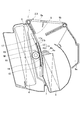
- FIG. 1 is a perspective view of a sliding door mechanism according to the first embodiment of the present invention.
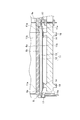
- FIG. 2 is a longitudinal sectional view of the sliding door mechanism according to the first embodiment of the present invention.
- FIG. 3 is a cross-sectional view of the sliding door mechanism according to the first embodiment of the present invention in a cross section that does not intersect the intermediate horizontal seal surface.
- FIG. 4 is a cross-sectional view of the sliding door mechanism according to the first embodiment of the present invention at a cross section intersecting with the intermediate horizontal seal surface.
- FIG. 5 is a perspective view of the door body according to the first embodiment of the present invention.
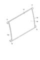
- FIG. 6 is a perspective view of a slide door including a door body and an elastic member according to the first embodiment of the present invention.
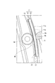
- FIG. 7 is an enlarged cross-sectional view of a main part of the slide door mechanism according to the first embodiment of the present invention.
- (First embodiment) 1 to 7 show a first embodiment of the present invention.
- FIG. 1 is a perspective view of a sliding door mechanism M according to this embodiment.
- FIG. 2 is a longitudinal sectional view of the sliding door mechanism M according to this embodiment.
- the sliding door mechanism M of this embodiment is provided in the vehicle air conditioner 1 shown in FIG.
- vertical direction and lateral direction are defined based on the moving direction of the air mix door 11 described later. Specifically, the “vertical direction” is defined as the moving direction of the air mix door 11, and the “lateral direction” is a direction in which the air mix door 11 extends and is orthogonal to the moving direction of the air mix door 11. Defined as the direction to do.
- the vehicle air conditioner 1 has air conditioning units 2 and 3 arranged on both sides in the vehicle width direction, and independently air-conditions a driver seat and a passenger seat in a passenger compartment (not shown).
- Each air conditioning unit 2 and 3 is provided with an air conditioning case 6 (case) in which an evaporator 4 and a heater core 5 are arranged.
- the air conditioning case 6 includes a first passage 7 through which the air passing through the evaporator 4 passes through the heater core 5 and a second passage 8 through which the air passing through the evaporator 4 bypasses the heater core 5.
- an outside air introduction port (not shown) for introducing outside air that is air outside the vehicle compartment and an inside air introduction port for introducing inside air that is air inside the vehicle compartment (see FIG. Not shown).
- the sucked air is converted into conditioned air at a desired temperature by the evaporator 4 and the heater core 5. Downstream of the heater core 5, a defroster outlet 9a, a vent outlet 9b, and a foot outlet 9c for blowing conditioned air into the passenger compartment are provided.
- the sliding door mechanism M of the present embodiment slides between a first switching position that closes the first passage 7 and a second switching position that closes the second passage 8.
- the air mix door 11 (sliding door) is provided to change the mixing ratio of the hot air and the cold air.
- the air mix door 11 moves to an intermediate position between the first switching position and the second switching position, and the first passage 7 and the second passage 8 are partially opened. .
- a part of the blast is heated by the heater core 5 to create an intermediate temperature blast.
- the air mix door 11 rises to the second switching position and closes the second passage 8, so that all the air is heated by the heater core 5 through the first passage 7 and hot air is created.
- the ratio between the air flowing through the heater core 5 and the air blowing bypassing the heater core 5 is adjusted. By adjusting this ratio, conditioned air having a desired temperature is generated.
- the air mix door 11 has a door body 12 and an elastic member 13.
- the elastic member 13 is provided with respect to the door main body 12 on the side of the vertical seal surface 6a and the intermediate horizontal seal surface 6b described later (the right side in FIG. 2).
- the elastic member 13 is formed of a urethane foam material and is attached to the door body 12.
- the door body 12 extends in the moving direction of the air mix door 11 and is formed in a rectangular shape that is long in the lateral direction.
- the door body 12 is curved toward the downstream direction of air blowing (the right direction in FIG. 2).
- the door body 12 is provided with a rack 14 arranged in the moving direction of the air mix door 11 and a pair of left and right guide pins 15 protruding from the door body 12 in a direction perpendicular to the moving direction of the air mix door 11. Yes.
- the racks 14 are arranged on both the left and right sides of the door body 12 in the lateral direction.
- the guide pins 15 are arranged at four places in total on the left and right sides of the door body 12 and on the upper and lower sides.
- the air conditioning case 6 meshes with the rack 14 and is driven by an electric motor (not shown), and a pair of guide grooves 17 extending in the moving direction of the air mix door 11 and guiding each guide pin 15. And are provided.
- the air conditioning case 6 is provided with a pair of left and right vertical seal surfaces 6a extending in the vertical direction and an intermediate horizontal seal surface 6b extending in the horizontal direction.
- FIG. 3 and 4 show how the air mix door 11, the vertical seal surface 6a, and the intermediate horizontal seal surface 6b are in close contact with each other in the slide door mechanism M at the intermediate position.
- FIG. 3 is a cross-sectional view of the slide door mechanism M according to the present embodiment in a cross section that does not intersect the intermediate horizontal seal surface 6b.
- FIG. 4 is a cross-sectional view of the slide door mechanism M according to this embodiment in a cross section that intersects the intermediate horizontal seal surface 6b.
- the intermediate horizontal seal surface 6b is provided on an intermediate member 6c disposed at a position where the first passage 7 and the second passage 8 are partitioned.
- the door body 12 is formed with a surface 12 a that faces the vertical seal surface 6 a with the elastic member 13 interposed therebetween in the movement process between the first switching position and the second switching position. Yes. Further, the door body 12 is formed with a surface 12b that faces the intermediate lateral seal surface 6b with the elastic member 13 interposed therebetween in the process of movement between the first switching position and the second switching position.
- the surface 12b is formed as a concave surface that is recessed from the surface 12a. Therefore, the distance Hb to the surface 12b along the vertical direction with respect to the intermediate horizontal seal surface 6b when the intermediate horizontal seal surface 6b and the surface 12b face each other is the distance when the vertical seal surface 6a and the surface 12a face each other.
- the distance Ha is greater than the distance Ha to the surface 12a along the vertical direction with respect to the vertical seal surface 6a.
- the distance Hb is greater than the distance Ha, and therefore when sandwiched between the intermediate lateral seal surface 6b and the surface 12b.
- the amount of deformation of the elastic member 13 is smaller than the amount of deformation of the elastic member 13 when sandwiched between the vertical seal surface 6a and the surface 12a.
- the pressure applied to the intermediate horizontal seal surface 6b from the elastic member 13 in contact with the intermediate horizontal seal surface 6b is smaller than the pressure applied to the vertical seal surface 6a from the elastic member 13 in contact with the vertical seal surface 6a. Therefore, the contact force between the intermediate horizontal seal surface 6 b and the elastic member 13 is configured to be lower than the contact force between the vertical seal surface 6 a and the elastic member 13.
- the upper end and lower end of the door body 12 are closer to the vertical seal surface 6a and the intermediate horizontal seal surface 6b than the surface 12b corresponding to the intermediate horizontal seal surface 6b, similarly to the surface 12a corresponding to the vertical seal surface 6a. It protrudes.
- the door main body 12 corresponds to the intermediate horizontal seal surface 6b. Since the surface 12b to be depressed is formed as a concave surface that is recessed from the surface 12a corresponding to the vertical seal surface 6a, the central portion 11b is recessed from the peripheral edge 11a of the air mix door 11 as shown in FIG.
- the left and right peripheral edges 11a of the air mix door 11 are in close contact with the vertical seal surface 6a and on the vertical seal surface 6a. Slide. Therefore, the elastic member 13 is elastically deformed from the position indicated by the two-dot chain line in FIG. 4 to the position indicated by the solid line in FIG. 4 at the left and right peripheral edges 11 a of the air mix door 11 and the vertical seal between the air mix door 11 and the air conditioning case 6. The space between the surface 6 a is sealed, and a sliding resistance is generated between the elastic member 13 and the vertical sealing surface 6 a of the air conditioning case 6.
- the central portion 11b of the air mix door 11 is in close contact with the intermediate horizontal seal surface 6b and slides on the intermediate horizontal seal surface 6b. Therefore, the elastic member 13 is elastically deformed from the position shown by the two-dot chain line in FIG. 4 to the position shown by the solid line in FIG. The space between the surface 6b is sealed.
- the contact force between the intermediate horizontal sealing surface 6b and the elastic member 13 is the vertical sealing surface 6a and the elastic member 13. Therefore, the sliding resistance between the elastic member 13 and the intermediate horizontal sealing surface 6b of the air conditioning case 6 can be reduced.
- the position of the surface 12b is used as a method of configuring the contact force between the intermediate horizontal seal surface 6b and the elastic member 13 to be lower than the contact force between the vertical seal surface 6a and the elastic member 13, the position of the surface 12b is used.
- the method of making the deformation amount of a certain elastic member 13 smaller than the deformation amount of the elastic member 13 at the position of the surface 12a has been described, the present invention is not limited to this.
- the elastic member may be formed such that the thickness of the elastic member itself in the region corresponding to the intermediate horizontal sealing surface of the case is thinner than the thickness of the elastic member itself in the region corresponding to the vertical sealing surface.
- the distance between the case's intermediate horizontal seal surface and the slide door slide locus position is set to the distance between the vertical seal surface and the slide door slide locus position. It can also arrange
- the left and right edges of the slide door are in close contact with the vertical seal surface of the case and slide on the vertical seal surface. Therefore, the elastic member is elastically deformed at the left and right peripheral edges of the slide door to seal between the slide door and the sealing surface of the case. Further, when the center portion of the sliding door is in close contact with the intermediate horizontal seal surface and slides on the intermediate horizontal seal surface, the close contact force between the intermediate horizontal seal surface and the elastic member is the close contact force between the vertical seal surface and the elastic member. Lower. Therefore, the sliding resistance between the elastic member and the intermediate lateral seal surface of the case can be reduced. Therefore, the driving force of the slide door can be reduced.
Landscapes
- Engineering & Computer Science (AREA)
- Mechanical Engineering (AREA)
- Chemical & Material Sciences (AREA)
- Combustion & Propulsion (AREA)
- Physics & Mathematics (AREA)
- Thermal Sciences (AREA)
- General Engineering & Computer Science (AREA)
- Air-Conditioning For Vehicles (AREA)
Abstract
ケース(6)に、第1切換位置と第2切換位置との間でスライド移動するエアミッスドア(11)と、第1切換位置と第2切換位置の間の移動過程でドア(11)の左右の周縁(11a)が密着する縦シール面(6a)と、移動過程でドア(11)の左右の周縁(11a)より中央部(11b)が密着する中間横シール面(6b)とが設けられ、ドア(11)は、ドア本体(12)と、シール面(6a,6b)側に設けられた弾性部材(13)とを有し、中間横シール面(6b)と弾性部材(13)間の密着力が縦シール面(6a)と弾性部材(13)間の密着力より低く構成されている。
Description
本発明は、ケース内の通路を開閉するスライドドアを備えたスライドドア機構に関する。
従来、ケース内の通路を開閉するスライドドアを備えたスライドドア機構が提案されている(特許文献1参照)。
このようなスライドドア機構は、車両用空調装置のケースに移動可能に設けられ、ケース内の通路を開閉するスライドドアを備えている。ケースには、スライドドアが密着するシール面が設けられている。
スライドドアには、ケースとスライドドアとの間をシールする弾性部材が配置されている。弾性部材は、スライドドアの両面のうち、ケースのシール面の側に設けられている。
上記構成では、ケース内で移動するスライドドアの弾性部材がケースのシール面に密着することにより、弾性部材が弾性変形してスライドドアとケースとの間がシールされる。
しかしながら、特許文献1のスライドドア機構では、スライドドアの弾性部材との接触面積が大きいシール面において弾性部材との摺動抵抗が大きい。そのため、スライドドアを駆動するために比較的大きな力を要するという課題がある。
本発明は、前述した課題を解決すべくなされた発明であり、スライドドアとケースとの間をシールする弾性部材とシール面との間の摺動抵抗を減らして、スライドドアの駆動力を低減することができるスライドドア機構を提供することを目的とする。
本発明は、第1通路と第2通路を設けたケースと、第1通路を閉塞する第1切換位置と第2通路を閉塞する第2切換位置との間でスライド移動するスライドドアと、を有するスライドドア機構であって、ケースには、第1切換位置と第2切換位置の間の移動過程でスライドドアの左右の周縁が密着する縦シール面が設けられ、第1通路と第2通路の間を仕切る位置には、第1切換位置と第2切換位置の間の移動過程でスライドドアの左右の周縁より中央部が密着する中間横シール面が設けられ、スライドドアは、ドア本体と、縦シール面及び中間横シール面の側に設けられた弾性部材とを有し、中間横シール面と弾性部材の間の密着力が、縦シール面と弾性部材の間の密着力より低く構成されていることを特徴とする。
本発明において、ドア本体には、中間横シール面に対応する面が縦シール面に対応する面より窪む凹面としてされていてもよい。
本発明において、弾性部材は、中間横シール面に対応する領域が縦シール面に対応する領域より肉厚が薄く形成されていてもよい。
本発明において、ケースは、内部にエバポレータとヒータコアが配置された空調ケースであってもよい。また、第1通路は、エバポレータを通過した送風がヒータコアを通る通路であってもよい。第2通路は、エバポレータを通過した送風がヒータコアをバイパスする通路であってもよい。スライドドアは、送風の温風と冷風の混合割合を可変するエアミックスドアであってもよい。
以下、本発明の実施形態を図面に基づいて説明する。
(第1実施形態)
図1~図7は本発明の第1実施形態を示す。
図1~図7は本発明の第1実施形態を示す。
図1は、本実施形態に係るスライドドア機構Mの斜視図である。また、図2は、本実施形態に係るスライドドア機構Mの縦断面図である。本実施形態のスライドドア機構Mは、図2に示す車両用空調装置1に設けられている。
「縦方向」「横方向」との用語は、後述するエアミックスドア11の移動方向に基づいて定義される。具体的には、「縦方向」は、エアミックスドア11の移動方向として定義され、「横方向」は、エアミックスドア11の延在する方向であって、エアミックスドア11の移動方向と直交する方向として定義される。
車両用空調装置1は、車両幅方向の両側に配置される空調部2、3を有し、車室(図示せず)の運転席と助手席を独立して空調する。
各空調部2、3には、内部にエバポレータ4とヒータコア5が配置された空調ケース6(ケース)が設けられている。
空調ケース6は、エバポレータ4を通過した送風がヒータコア5を通る第1通路7と、エバポレータ4を通過した送風がヒータコア5をバイパスする第2通路8を有する。
第1通路7及び第2通路8の最上流には、車室外の空気である外気を導入する外気導入口(図示せず)と、車室内の空気である内気を導入する内気導入口(図示せず)が設けられている。
送風機(図示せず)によって第1通路7及び第2通路8に内気や外気を吸い込むと、吸い込まれた空気は、エバポレータ4とヒータコア5によって所望温度の空調風とされる。ヒータコア5の下流には、車室内に空調風を吹き出すデフロスタ吹出口9aとベント吹出口9bとフット吹出口9cが設けられている。
図1及び図2に示すように、本実施形態のスライドドア機構Mは、第1通路7を閉塞する第1切換位置と第2通路8を閉塞する第2切換位置との間でスライド移動し、送風の温風と冷風の混合割合を可変するエアミックスドア11(スライドドア)を備えている。
図2に示すように、中間モードでは、第1切換位置と第2切換位置の間の中間位置にエアミックスドア11が移動して、第1通路7及び第2通路8がそれぞれ部分的に開く。その結果、送風の一部がヒータコア5で加熱され、中間温度の送風が作成される。
フルクールモードでは、エアミックスドア11が第1切換位置まで下降して第1通路7を閉じるので、全ての送風が第2通路8を通ってヒータコア5をバイパスして冷風が生成される。
フルホットモードでは、エアミックスドア11が第2切換位置まで上昇して第2通路8を閉じるので、全ての送風が第1通路7を通ってヒータコア5で加熱され、温風が作成される。
エアミックスドア11が、第1切換位置と第2切換位置との間で連続的にスライド移動することにより、ヒータコア5を流れる送風とヒータコア5をバイパスする送風との割合が調整される。この割合の調整によって所望温度の空調風を生成する。
エアミックスドア11は、ドア本体12と、弾性部材13とを有する。弾性部材13は、ドア本体12に対して、後述する縦シール面6a及び中間横シール面6bの側(図2の右側)に設けられる。
弾性部材13は、ウレタンフォーム材から形成され、ドア本体12に貼り付けられている。ドア本体12は、エアミックスドア11の移動方向に延びると共に、横方向に長い四角形状に形成されている。ドア本体12は、送風の下流方向(図2の右方向)に向かって湾曲している。
ドア本体12には、エアミックスドア11の移動方向に配置されるラック14と、ドア本体12からエアミックスドア11の移動方向と直交する方向へ突出する左右一対のガイドピン15とが設けられている。
ラック14は、ドア本体12の横方向における左右両側に配置されている。ガイドピン15は、ドア本体12の左右両側、且つ、上部及び下部の合計で4箇所に配置されている。
空調ケース6には、ラック14と噛み合い、電動モータ(図示せず)で駆動される駆動歯車16と、エアミックスドア11の移動方向に延びて、各ガイドピン15を案内する一対のガイド溝17とが設けられている。
空調ケース6には、縦方向に延びる左右一対の縦シール面6aと、横方向に延びる中間横シール面6bが設けられている。
図3及び図4には、中間位置にあるスライドドア機構Mにおける、エアミックスドア11と縦シール面6a及び中間横シール面6bとの密着の様子が示されている。図3は、本実施形態に係るスライドドア機構Mの、中間横シール面6bと交差しない断面での横断面図である。また、図4は、本実施形態に係るスライドドア機構Mの、中間横シール面6bと交差する断面での横断面図である。
図3及び図4に示すように、第1切換位置と第2切換位置の間の移動過程で、エアミックスドア11の左右の周縁11aが各縦シール面6aに密着する。
また、図4に示すように、第1切換位置と第2切換位置の間の移動過程で、左右の周縁11aによって挟まれるエアミックスドア11の中央部11bが、中間横シール面6bに密着する。
中間横シール面6bは、第1通路7と第2通路8の間を仕切る位置に配置された中間部材6cに設けられている。
ここで、図5に示すように、ドア本体12には、第1切換位置と第2切換位置の間の移動過程において弾性部材13を挟んで縦シール面6aと対向する面12aが形成されている。また、ドア本体12には、第1切換位置と第2切換位置の間の移動過程において弾性部材13を挟んで中間横シール面6bと対向する面12bが形成されている。
なお、面12bは、面12aより窪む凹面として形成されている。よって、中間横シール面6bと面12bとが対向する際の中間横シール面6bに対して垂直方向に沿った面12bまでの距離Hbは、縦シール面6aと面12aとが対向する際の、縦シール面6aに対して垂直方向に沿った面12aまでの距離Haよりも大きくなる。
挟まれる前の弾性部材13の肉厚が、ドア本体12の全面にわたって同程度に形成されている場合、距離Hbは距離Haよりも大きいため、中間横シール面6bと面12bで挟まれたときの弾性部材13の変形量は、縦シール面6aと面12aで挟まれたときの弾性部材13の変形量よりも小さくなる。
よって、中間横シール面6bと接する弾性部材13から中間横シール面6bに加わる圧力は、縦シール面6aと接する弾性部材13から縦シール面6aに加わる圧力よりも小さくなる。そのため、中間横シール面6bと弾性部材13間の密着力は、縦シール面6aと弾性部材13間の密着力より低くなるように構成されている。
なお、ドア本体12の上端及び下端は、縦シール面6aに対応する面12aと同様に、中間横シール面6bに対応する面12bよりも、縦シール面6a及び中間横シール面6bの側に突出している。
上記構成において、エアミックスドア11の組立時にドア本体12に対して縦シール面6a及び中間横シール面6bの側に弾性部材13を貼り付けると、ドア本体12に、中間横シール面6bに対応する面12bが縦シール面6aに対応する面12aより窪む凹面が形成されているので、図6に示すように、エアミックスドア11の周縁11aより中央部11bが窪む。
このようにして組み立てたエアミックスドア11の第1切換位置と第2切換位置の間の移動過程では、エアミックスドア11の左右の周縁11aが縦シール面6aに密着して縦シール面6a上を摺動する。そのため、エアミックスドア11の左右の周縁11aで弾性部材13が、図4の二点鎖線で示す位置から図4の実線で示す位置まで弾性変形してエアミックスドア11と空調ケース6の縦シール面6aとの間がシールされ、弾性部材13と空調ケース6の縦シール面6aとの間で摺動抵抗が生じる。
また、エアミックスドア11の中央部11bが中間横シール面6bに密着して中間横シール面6b上を摺動する。そのため、エアミックスドア11の中央部11bで弾性部材13が、図4の二点鎖線で示す位置から図4の実線で示す位置まで弾性変形してエアミックスドア11と空調ケース6の中間横シール面6bとの間がシールされる。
本実施形態によれば、エアミックスドア11の第1切換位置と第2切換位置の間の移動過程において、中間横シール面6bと弾性部材13間の密着力が縦シール面6aと弾性部材13間の密着力より低いので、弾性部材13と空調ケース6の中間横シール面6bとの間の摺動抵抗を減らすことができる。
従って、弾性部材13と空調ケース6との間の摺動抵抗を減らすことができ、エアミックスドア11の駆動力を低減することができる。
(変形例)
前述した第1実施形態では、車両用空調装置1の空調ケース6に設けられるエアミックスドア11を例示したが、本発明はこれに限定されない。エアミックスドアの代わりに、他のスライドドアであってもよい。
前述した第1実施形態では、車両用空調装置1の空調ケース6に設けられるエアミックスドア11を例示したが、本発明はこれに限定されない。エアミックスドアの代わりに、他のスライドドアであってもよい。
上述した第1実施形態では、中間横シール面6bと弾性部材13間の密着力を、縦シール面6aと弾性部材13間の密着力より低くなるように構成する方法として、面12bの位置にある弾性部材13の変形量を、面12aの位置にある弾性部材13の変形量より小さくするという方法を説明したが、本発明はこれに限定されない。
例えば、ケースの中間横シール面に対応する領域における弾性部材自体の肉厚が、縦シール面に対応する領域における弾性部材自体の肉厚より薄くなるように、弾性部材を形成してもよい。
また、ケースの中間横シール面をスライドドアから離間させることで、ケースの中間横シール面とスライドドアのスライド軌跡位置の間の距離を、縦シール面とスライドドアのスライド軌跡位置の間の距離よりも大きくなるように配置することもできる。この場合も、スライドドアの第1切換位置と第2切換位置の間の移動過程では、弾性部材とケースの中間横シール面との間の摺動抵抗を減らすことができるので、スライドドアの駆動力を低減できる。
以上、本発明の実施形態について説明したが、これらの実施形態は本発明の理解を容易にするために記載された単なる例示に過ぎず、本発明は当該実施形態に限定されるものではない。本発明の技術的範囲は、上記実施形態で開示した具体的な技術事項に限らず、そこから容易に導きうる様々な変形、変更、代替技術なども含むものである。
本出願は、2016年3月14日に出願された日本国特許願第2016-049387号に基づく優先権を主張しており、この出願の全内容が参照により本明細書に組み込まれる。
本発明によれば、スライドドアの第1切換位置と第2切換位置の間の移動過程において、スライドドアの左右の周縁がケースの縦シール面に密着して縦シール面上を摺動する。そのため、スライドドアの左右の周縁で弾性部材が弾性変形してスライドドアとケースのシール面との間がシールされる。また、スライドドアの中央部が中間横シール面に密着して中間横シール面上を摺動する際、この中間横シール面と弾性部材間の密着力が縦シール面と弾性部材間の密着力より低い。そのため、弾性部材とケースの中間横シール面との間の摺動抵抗を減らすことができる。従って、スライドドアの駆動力を低減することができる。
M スライドドア機構
4 エバポレータ
5 ヒータコア
6 空調ケース(ケース)
6a 縦シール面
6b 中間横シール面
7 第1通路
8 第2通路
11 エアミックスドア(スライドドア)
11a 周縁
11b 中央部
12 ドア本体
12a、12b 面
13 弾性部材
4 エバポレータ
5 ヒータコア
6 空調ケース(ケース)
6a 縦シール面
6b 中間横シール面
7 第1通路
8 第2通路
11 エアミックスドア(スライドドア)
11a 周縁
11b 中央部
12 ドア本体
12a、12b 面
13 弾性部材
Claims (4)
- 第1通路と第2通路を設けたケースと、
前記第1通路を閉塞する第1切換位置と前記第2通路を閉塞する第2切換位置との間でスライド移動するスライドドアと、
を有するスライドドア機構であって、
前記ケースには、前記第1切換位置と前記第2切換位置の間の移動過程で前記スライドドアの左右の周縁が密着する縦シール面が設けられ、
前記第1通路と前記第2通路の間を仕切る位置には、前記第1切換位置と前記第2切換位置の間の移動過程で前記スライドドアの左右の周縁より中央部が密着する中間横シール面が設けられ、
前記スライドドアは、ドア本体と、前記縦シール面及び前記中間横シール面の側に設けられた弾性部材とを有し、
前記中間横シール面と前記弾性部材の間の密着力が、前記縦シール面と前記弾性部材の間の密着力より低く構成されていること
を特徴とするスライドドア機構。 - 請求項1に記載のスライドドア機構であって、
前記ドア本体には、前記中間横シール面に対応する面が前記縦シール面に対応する面より窪む凹面として形成されていること
を特徴とするスライドドア機構。 - 請求項1又は2に記載のスライドドア機構であって、
前記弾性部材は、前記中間横シール面に対応する領域が前記縦シール面に対応する領域より肉厚が薄く形成されていること
を特徴とするスライドドア機構。 - 請求項1~3のいずれか1項に記載のスライドドア機構であって、
前記ケースは、内部にエバポレータとヒータコアが配置された空調ケースであり、
前記第1通路は、前記エバポレータを通過した送風が前記ヒータコアを通る通路であり、
前記第2通路は、前記エバポレータを通過した送風が前記ヒータコアをバイパスする通路であり、
前記スライドドアは、送風の温風と冷風の混合割合を可変するエアミックスドアであること
を特徴とするスライドドア機構。
Applications Claiming Priority (2)
| Application Number | Priority Date | Filing Date | Title |
|---|---|---|---|
| JP2016049387A JP2017165121A (ja) | 2016-03-14 | 2016-03-14 | スライドドア機構 |
| JP2016-049387 | 2016-03-14 |
Publications (1)
| Publication Number | Publication Date |
|---|---|
| WO2017159406A1 true WO2017159406A1 (ja) | 2017-09-21 |
Family
ID=59851842
Family Applications (1)
| Application Number | Title | Priority Date | Filing Date |
|---|---|---|---|
| PCT/JP2017/008512 Ceased WO2017159406A1 (ja) | 2016-03-14 | 2017-03-03 | スライドドア機構 |
Country Status (2)
| Country | Link |
|---|---|
| JP (1) | JP2017165121A (ja) |
| WO (1) | WO2017159406A1 (ja) |
Citations (4)
| Publication number | Priority date | Publication date | Assignee | Title |
|---|---|---|---|---|
| JPH1058947A (ja) * | 1996-08-26 | 1998-03-03 | Denso Corp | 空気通路切替装置および車両用空調装置 |
| JP2001347820A (ja) * | 2000-01-13 | 2001-12-18 | Denso Corp | 空気通路切替装置および車両用空調装置 |
| JP2004338605A (ja) * | 2003-05-16 | 2004-12-02 | Keihin Corp | 通路切換装置 |
| JP2009179200A (ja) * | 2008-01-31 | 2009-08-13 | Denso Corp | 空調装置 |
-
2016
- 2016-03-14 JP JP2016049387A patent/JP2017165121A/ja active Pending
-
2017
- 2017-03-03 WO PCT/JP2017/008512 patent/WO2017159406A1/ja not_active Ceased
Patent Citations (4)
| Publication number | Priority date | Publication date | Assignee | Title |
|---|---|---|---|---|
| JPH1058947A (ja) * | 1996-08-26 | 1998-03-03 | Denso Corp | 空気通路切替装置および車両用空調装置 |
| JP2001347820A (ja) * | 2000-01-13 | 2001-12-18 | Denso Corp | 空気通路切替装置および車両用空調装置 |
| JP2004338605A (ja) * | 2003-05-16 | 2004-12-02 | Keihin Corp | 通路切換装置 |
| JP2009179200A (ja) * | 2008-01-31 | 2009-08-13 | Denso Corp | 空調装置 |
Also Published As
| Publication number | Publication date |
|---|---|
| JP2017165121A (ja) | 2017-09-21 |
Similar Documents
| Publication | Publication Date | Title |
|---|---|---|
| CN104097486B (zh) | 具有柔性叶片的空气管道组件 | |
| CN105517819B (zh) | 车辆用空调单元 | |
| JP6318931B2 (ja) | 空気吹出装置 | |
| JP5568642B2 (ja) | 車両用空気調和装置 | |
| US20130149951A1 (en) | Air discharge system of hvac system for vehicle | |
| US20160311291A1 (en) | Air conditioning unit | |
| JP2000135912A (ja) | 通風路切替装置 | |
| JP2015164837A (ja) | 車両用空気調和装置 | |
| CN103237672A (zh) | 车辆用空调装置 | |
| CN103158493B (zh) | 车辆用空调装置 | |
| WO2016002128A1 (ja) | 車両用シート空調装置 | |
| CN102216108B (zh) | 车辆用内部装饰部件以及其制造方法和其成形金属模 | |
| WO2014155805A1 (ja) | 車両用空気調和システム | |
| WO2017159406A1 (ja) | スライドドア機構 | |
| JP2008100593A (ja) | 通風路切替装置および車両用空調装置 | |
| JP2017171136A (ja) | スライドドア機構 | |
| JP2009179200A (ja) | 空調装置 | |
| CN106103150A (zh) | 车辆用空调装置 | |
| JP2001198955A (ja) | 通風路切替用ドアの製造方法 | |
| WO2017159417A1 (ja) | スライドドア機構 | |
| JP2015123834A (ja) | スライドドア装置 | |
| JP4277644B2 (ja) | 車両用空調装置 | |
| US20170057324A1 (en) | Motor vehicle ventilation device | |
| JP2008105562A (ja) | 通風路切替装置および車両用空調装置 | |
| JP6118607B2 (ja) | 車両用空気調和装置 |
Legal Events
| Date | Code | Title | Description |
|---|---|---|---|
| NENP | Non-entry into the national phase |
Ref country code: DE |
|
| 121 | Ep: the epo has been informed by wipo that ep was designated in this application |
Ref document number: 17766409 Country of ref document: EP Kind code of ref document: A1 |
|
| 122 | Ep: pct application non-entry in european phase |
Ref document number: 17766409 Country of ref document: EP Kind code of ref document: A1 |