WO2014155805A1 - 車両用空気調和システム - Google Patents
車両用空気調和システム Download PDFInfo
- Publication number
- WO2014155805A1 WO2014155805A1 PCT/JP2013/079748 JP2013079748W WO2014155805A1 WO 2014155805 A1 WO2014155805 A1 WO 2014155805A1 JP 2013079748 W JP2013079748 W JP 2013079748W WO 2014155805 A1 WO2014155805 A1 WO 2014155805A1
- Authority
- WO
- WIPO (PCT)
- Prior art keywords
- air
- vehicle
- outlet
- conditioning system
- air conditioning
- Prior art date
Links
Images


Classifications
-
- B—PERFORMING OPERATIONS; TRANSPORTING
- B60—VEHICLES IN GENERAL
- B60H—ARRANGEMENTS OF HEATING, COOLING, VENTILATING OR OTHER AIR-TREATING DEVICES SPECIALLY ADAPTED FOR PASSENGER OR GOODS SPACES OF VEHICLES
- B60H1/00—Heating, cooling or ventilating [HVAC] devices
- B60H1/24—Devices purely for ventilating or where the heating or cooling is irrelevant
- B60H1/241—Devices purely for ventilating or where the heating or cooling is irrelevant characterised by the location of ventilation devices in the vehicle
- B60H1/246—Devices purely for ventilating or where the heating or cooling is irrelevant characterised by the location of ventilation devices in the vehicle located in the interior of the vehicle or in or below the floor
-
- B—PERFORMING OPERATIONS; TRANSPORTING
- B60—VEHICLES IN GENERAL
- B60H—ARRANGEMENTS OF HEATING, COOLING, VENTILATING OR OTHER AIR-TREATING DEVICES SPECIALLY ADAPTED FOR PASSENGER OR GOODS SPACES OF VEHICLES
- B60H1/00—Heating, cooling or ventilating [HVAC] devices
- B60H1/00271—HVAC devices specially adapted for particular vehicle parts or components and being connected to the vehicle HVAC unit
- B60H1/00285—HVAC devices specially adapted for particular vehicle parts or components and being connected to the vehicle HVAC unit for vehicle seats
Definitions
- the present invention relates to an air conditioning system for a vehicle that efficiently performs air conditioning between a front seat side and a rear seat side.
- the vehicle air conditioning system 100 shown in FIG. 17 converts the air sucked into the air passage by the blower into the desired conditioned air by the heat exchange unit, and this conditioned air is blown out (the def outlet 111, the vent outlet 112). And from the foot outlet 113).
- the vehicle air conditioning system 100 includes air outlets 111, 112, 113, an air conditioner 110, and a suction duct 120 that extends from the air conditioner 110 to below the front seat 130.
- the suction duct 120 has a front seat lower suction port 121 for sucking conditioned air blown from the blower outlet below the front seat 130.
- the front seat 130 can be preferentially air-conditioned, but in order to blow the conditioned air toward the rear seat 140 side, as shown by a two-dot chain line in FIG.
- the suction duct 120 installation spaces had to be secured.
- An object of the present invention is to provide a vehicle air conditioning system that can be used.
- the present invention has the following characteristics.
- the first feature of the present invention is that an air conditioner that converts air sucked into a blower passage by a blower into a desired conditioned air by a heat exchange unit and blows the air into a passenger compartment, and the heat exchange unit of the blower passage.
- a blow duct having a blowout port that extends from the downstream side to the lower side of the front seat and blows the conditioned air into the vehicle compartment under the front seat, and a wind direction adjusting means that adjusts the direction of the conditioned air blown from the blowout port It is a summary to provide.
- the air outlet is composed of a front air outlet that blows conditioned air toward the front of the vehicle and a rear air outlet that blows conditioned air toward the rear of the vehicle, and the wind direction adjusting means is an air conditioned air that blows out from the front air outlet and the rear air outlet. It is preferable to adjust the air volume.
- the wind direction adjusting means is preferably constituted by an opening / closing member capable of opening and closing the air outlet by the conditioned air passing through the air outlet duct.
- the wind direction adjusting means may include partition means for rotating between a partition position that partitions the lower space of the front seat into a front side and a rear side of the vehicle and an open position that does not partition the front side and the rear side of the vehicle. preferable.
- the partitioning unit is provided apart from the air outlet, and blows air in front of the vehicle when the conditioned air blows at the partition position, and blows the air conditioned air to the rear of the vehicle at the open position by opening the air outlet.
- the partition means preferably has a guide portion that guides the conditioned air to the front of the vehicle at the partition position.
- An expansion / contraction partitioning means that communicates with the blowout duct and is provided below the front seat and extends and contracts in the vertical direction by the conditioned air passing through the blowout duct to partition the space under the front seat into the front side and the rear side of the vehicle. It is preferable to provide.
- the blowout duct includes a main body duct and a tip member that is provided so as to be rotatable with respect to the main body duct and has one blower outlet.
- the wind direction adjusting means rotates the tip member to change the direction of the blower outlet. It is preferable to have switching means for switching to the front or rear of the vehicle.
- the air conditioner has a foot air outlet that blows conditioned air from the front of the vehicle to the lower part of the front seat, and the conditioned air blown from the air outlet to the front of the vehicle is preferably larger than the air conditioned air that blows from the foot air outlet. .
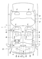
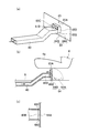
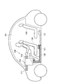
- FIG. 1 is a schematic side view showing the vehicle air conditioning system according to the first embodiment.
- FIG. 2 is a schematic plan view showing the vehicle air conditioning system according to the first embodiment.
- FIG. 3 is a schematic configuration diagram of the vehicle air conditioning system according to the first embodiment.
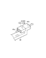
- FIG. 4 is a perspective view showing only the tip of the blowout duct according to the first embodiment.
- Fig.5 (a) is a perspective view which shows only the front-end
- FIG.5 (b) is a plane of the blowing duct which concerns on the modification 1 of 1st Embodiment.
- FIG. FIG. 6 is a perspective view showing only the tip of the outlet duct according to the second modification of the first embodiment.
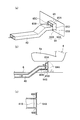
- FIG. 7 is a schematic configuration diagram of a vehicle air conditioning system according to the second embodiment.
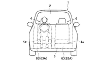
- FIG. 8 is a schematic front view showing the vehicle air conditioning system according to the second embodiment.
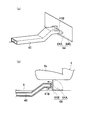
- Fig.9 (a) is a perspective view which shows the front-end
- FIG.9 (b) is a cross section showing the side which shows the front-end
- FIG. 10 (a), 10 (b), and 10 (c) are a perspective view, a cross-sectional view showing a side, and a cross-section showing a plan view, respectively, of the tip of a blowout duct according to Modification 1 of the third embodiment.
- FIG. 10 (a), 10 (b), and 10 (c) are a perspective view, a cross-sectional view showing a side, and a cross-section showing a plan view, respectively, of the tip of a
- FIG. 11 (a), 11 (b), and 11 (c) are a perspective view, a cross-sectional view showing a side, and a cross-section showing a plan view, respectively, of the tip of a blowout duct according to Modification 2 of the third embodiment.
- FIG. 12 (a), 12 (b), and 12 (c) are a perspective view, a cross-sectional view showing a side, and a cross-section showing a plan view, respectively, of the tip of a blowout duct according to Modification 3 of the third embodiment.
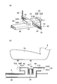
- FIG. FIG. 13 is a schematic side view showing the vehicle air conditioning system according to the fourth embodiment.
- FIG. 14 is a schematic configuration diagram of a vehicle air conditioning system according to the fourth embodiment.
- FIG. 15B are a perspective view and a cross-sectional view showing the side of the tip (contracted state of the expansion / contraction part) of the blowout duct according to the fourth embodiment, respectively.
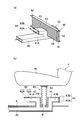
- FIG. 16A and FIG. 16B are a perspective view and a cross-sectional view showing the side of the tip (extended state of the expansion / contraction part) of the blowout duct according to the fourth embodiment, respectively.
- FIG. 17 is a schematic side view showing a vehicle air conditioning system according to the background art.
- the vehicle air conditioning system 10 is provided in an instrument panel 3 provided in the foremost part of the passenger compartment 2 of the vehicle 1.
- the passenger compartment 2 two front seats 4 for a driver seat and a passenger seat and one long rear seat 5 (see FIG. 2) are provided.
- Each front seat 4 has a seat cushion 4a, a seat back 4b, and a headrest 4c.
- the rear seat 5 has a seat cushion 5a, a seat back 5b, and two headrests 5c.
- a vehicle air conditioning system 10 provided in such a vehicle 1 includes an air conditioner 20 that supplies desired conditioned air into the passenger compartment 2, and a front seat 4 (seats).
- the blower duct 40 having the blower outlet 41 for blowing the conditioned air into the passenger compartment 2 below the cushion 4a), the wind direction adjusting means 60 for adjusting the direction of the conditioned air blown from the blower outlet 41, and the air conditioner 20 are operated.
- An operation panel (not shown) and a control unit (not shown) for controlling each part and performing various calculations are provided.
- the air conditioner 20 has an air conditioning unit 21 arranged inside the instrument panel 3. As shown in FIG. 3, an air passage 22 is formed in the air conditioning unit 21. In the uppermost stream of the air passage 22, an outside air introduction port 23 for introducing outside air that is air outside the passenger compartment 2 and an inside air that is provided below the seat cushion 4 a and introduces inside air that is air inside the passenger compartment 2. An inlet 24 is provided. The outside air introduction port 23 and the inside air introduction port 24 are opened and closed by two intake doors 25a and 25b.
- a blower 26 is provided for sucking inside air and outside air into the air passage 22 by rotation of the fan.
- an evaporator 27 and a heater core 28, which are heat exchange units, are arranged in this order, and a mix door 29 is provided between the evaporator 27 and the heater core 28.
- the evaporator 27 is a cooling source for blowing air.
- the evaporator 27 is arranged so that all the air passing through the air passage 22 passes through, and cools the air.
- the heater core 28 is a heat source for blowing air.
- the heater core 28 is disposed in a substantially half region of the air passage 22 and heats the air.
- the mix door 29 adjusts the ratio of the airflow that flows through the heater core 28 and the airflow that bypasses the heater core 28. Air-conditioned air at a desired temperature is produced according to the ratio of the air volume sent.
- an air conditioning outlet 30 for blowing conditioned air into the passenger compartment 2 is provided downstream of the heater core 28.
- the air-conditioning outlet 30 emits conditioned air toward the upper body of each occupant of the front seat 4 (driver seat side and passenger seat side) and the defroster outlet 31 that blows air-conditioned air toward the windshield (not shown). Vent outlets 32a and 32b for blowing out, and foot outlets 33a and 33b) as foot outlets for blowing air-conditioned air toward the lower body of each occupant on the driver's seat and passenger seat side.
- the defroster outlet 31 is opened and closed by a differential door 34, the vent outlets 32a and 32b are opened and closed by a vent door 35, and the foot outlets 33a and 33b are opened and closed by a foot door 36.
- the blowout duct 40 extends from the downstream side of the heat exchange part (evaporator 27 and heater core 28) of the air passage 22 to the lower side of the front seat 4, and is opened and closed by the blowout duct door 37. Specifically, the blowout duct 40 passes through the lower side of the floor portion 6 (floor panel) from the air passage 22, bends at a substantially right angle below the front seat 4, passes through the floor portion 6, and moves forward of the vehicle 1. And it branches back and is provided in T shape seeing from the side.
- the air outlet 41 described above is provided at the tip of the air outlet duct 40.
- the air outlet 41 includes a front air outlet 41A that blows conditioned air to the front of the vehicle 1 below the front seat 4, and a rear air outlet 41B that blows conditioned air to the rear of the vehicle 1 below the front seat 4. Yes.
- a wind direction adjusting means 60 is provided between the front air outlet 41A and the rear air outlet 41B.
- the wind direction adjusting means 60 adjusts the direction in which the conditioned air blows out toward at least one of the foot side of the front seat 4 and the foot side of the rear seat 5.
- the wind direction adjusting means 60 is configured by one open / close door 61 as an open / close member that can open and close the front air outlet 41A and the rear air outlet 41B.
- the open / close door 61 is provided at a branch point of the front outlet 41A and the rear outlet 41B of the outlet duct 40.
- the open / close door 61 includes a door main body 61A and a rotation shaft 61B provided on the front seat 4 side and serving as a rotation center of the door main body 61A.
- Such an open / close door 61 adjusts the air volume of the conditioned air blown from the front outlet 41A and the rear outlet 41B according to the stop position together with the outlet duct door 37.
- an actuator or a manual is mentioned.
- An operation panel (not shown) can command various air conditioning states. On the operation panel, an overall air conditioning mode for air conditioning the entire interior of the passenger compartment 2 and a zone air conditioning mode for preferentially air conditioning the space of the front seat 4 in the passenger compartment 2 can be selected.
- a control unit controls the air conditioner 20 by a command from an operation panel (not shown), and various doors (intake doors 25a and 25b, a mix door 29, a differential door 34, a vent door 35, a foot door 36, The switching of the blowout duct door 37 and the open / close door 61) is controlled.
- the control unit performs control so as to blow conditioned air from the rear outlet 41B.
- the control unit stops the conditioned air blown from the rear outlet 41B, and from the front outlet 41A. Control to blow conditioned air. Specific switching contents will be described later.
- the vehicle air conditioning system 10 includes the overall air conditioning mode (so-called normal air conditioning mode) and the zone air conditioning mode.
- the overall air conditioning mode so-called normal air conditioning mode
- the zone air conditioning mode is demonstrated.
- the foot air outlets 33a and 33b are opened and the air outlet 41 (the front air outlet 41A and the rear air outlet 41B) is also opened, and the conditioned air is blown out from the opened air outlet. Therefore, the conditioned air blown out from the air conditioner 20 into the passenger compartment 2 flows to almost the entire area of the passenger compartment 2, and the entire interior of the passenger compartment 2 is air-conditioned.
- the open / close door 61 does not necessarily need to open the front outlet 41A and the rear outlet 41B.
- the open / close door 61 can have the front outlet 41A as a closed position and the rear outlet 41B as an open position. The amount of conditioned air blown out from the front outlet 41A and the rear outlet 41B is adjusted by the stop position of the open / close door 61.
- Zone air conditioning mode In the zone air-conditioning mode, the conditioned air at a desired temperature is blown into the passenger compartment 2 from the foot outlets 33a and 33b and the front outlet 41A, as in the overall air-conditioning mode. That is, the foot outlets 33a and 33b are opened, the rear outlet 41B is closed and the front outlet 41A is opened, and the conditioned air is blown out from the opened outlet. At this time, the conditioned air blown out from the front outlet 41A to the front of the vehicle 1 is larger than the conditioned air blown out from the foot outlets 33a and 33b.
- the conditioned air blown into the passenger compartment 2 intensively passes around the front seat 4 (mainly the height position of the lower body of the occupant) and is connected to the inside air inlet 24 (step suction inlet 38 ( 2), the air is sucked by the suction force of the blower 26 and returned to the air conditioning unit 21.
- the conditioned air can be prevented from flowing into the space of the rear seat 5, and a zone air-conditioning region is formed in the front seat 4 in the passenger compartment 2.
- the air that the air conditioning apparatus 20 has sucked into the air passage 22 by the blower 26 is converted into desired conditioned air by the evaporator 27 and the heater core 28 that are heat exchange units. Convert. And the blower outlet 41 (front blower outlet 41A and rear blower outlet 41B) of the blower duct 40 extended from the downstream side of the evaporator 27 and heater core 28 which are the heat exchange parts arrange
- the conditioned air can be blown forward of the vehicle 1 when it is desired to air-condition the front seat 4,
- conditioned air can be blown out to the rear of the vehicle 1. That is, the conditioned air can be blown from either the front air outlet 41A or the rear air outlet 41B or both. For this reason, even if it does not extend the blowing duct 40 to the rear seat 5 side, the rear seat 5 can be air-conditioned. Therefore, the air conditioning of the front seat 4 side and the rear seat 5 side can be efficiently performed without securing the installation space for the blowout duct 40 on the rear seat 5 side.
- the blower outlet 41 of the blower duct 40 is comprised by 41 A of front blower outlets, and the rear blower outlet 41B, and it blows off air-conditioning wind only from 41 A of front blower outlets, or only from the rear blower outlet 41B.
- the conditioned air can be blown out from both the front outlet 41A and the rear outlet 41B.
- the opening / closing door 61 is provided in each of the front air outlet 41A and the rear air outlet 41B by adjusting the air volume of the conditioned air blown from the front air outlet 41A and the rear air outlet 41B depending on the stop position of the door 61. Compared to the case, only one open / close door 61 is required, and conditioned air can be blown out from at least one of the front outlet 41A and the rear outlet 41B.
- the air-conditioning air blown from the front air outlet 41 ⁇ / b> A to the front of the vehicle 1 blows out from the foot air outlets 33 a and 33 b that are foot air outlets that blow air-conditioned air from the front of the vehicle 1 to the lower side of the front seat 4.
- the foot air outlets 33 a and 33 b are foot air outlets that blow air-conditioned air from the front of the vehicle 1 to the lower side of the front seat 4.
- FIGS. 5A and 5B are diagrams showing only the tip of the blowout duct 40 according to the first modification.
- the blowout duct 40 is bent at a substantially right angle in the width direction of the vehicle 1, and is further bent at a substantially right angle in front of the vehicle 1. That is, the blowing duct 40 is provided in a U shape in plan view.
- the blowout duct 40 is bent and a front blowout port 41A is provided at the front end, and a rear blowout port 41B is provided on the rear side before the blowout duct 40 is bent.
- An opening / closing door 61 as a wind direction adjusting means 60 is provided at the position of the rear outlet 41B.
- the space between the front seat 4 side and the rear seat 5 side is ensured without securing the installation space for the blowing duct 40 on the rear seat 5 side. Air conditioning can be performed efficiently.
- the opening / closing door 61 is provided in each of the front air outlet 41A and the rear air outlet 41B by adjusting the air volume of the conditioned air blown from the front air outlet 41A and the rear air outlet 41B depending on the stop position of the door 61. Compared to the case, only one open / close door 61 is required, and conditioned air can be blown out from at least one of the front outlet 41A and the rear outlet 41B.
- FIG. 6 is a perspective view showing only the tip of the blowing duct 40 according to the second modification.
- the blowing duct 40 includes a main body duct 40A and a cylindrical tip member 40B that is provided so as to be rotatable with respect to the main body duct 40A and has one outlet 41.
- the distal end member 40B extends upward from the upper end of the distal end of the main body duct 40A and is bent at a substantially right angle. That is, the tip member 40B is provided in an L shape in side view.
- the wind direction adjustment means 60 has the switching means (for example, actuator) which is not shown in figure which switches the direction of one blower outlet 41 to the front or back of the vehicle 1 by rotating the front-end
- the space between the front seat 4 side and the rear seat 5 side is ensured without securing the installation space for the blowing duct 40 on the rear seat 5 side. Air conditioning can be performed efficiently.
- the wind direction adjusting means 60 switches the direction of one air outlet 41 to the front or rear of the vehicle 1 by rotating the tip member 40B, and to the front seat 4 side and the rear seat 5 side depending on the stop position.
- the ratio of the flowing air volume can be adjusted, and air conditioning between the front seat 4 side and the rear seat 5 side can be performed efficiently.
- FIG.7 and FIG.8 is a figure which shows the air conditioning system 10 for vehicles which concerns on 2nd Embodiment.
- symbol is attached
- the vehicle air conditioning system 10 according to the second embodiment differs from the vehicle air conditioning system 10 according to the first embodiment in the configuration of the wind direction adjusting means 60.
- the wind direction adjusting means 60 is configured by a front opening / closing door 62 that opens and closes the front outlet 41A and a rear opening / closing door 63 as a partitioning means that opens and closes the rear outlet 41B. ing.
- the front opening / closing door 62 has a door main body 62A and a rotation shaft 62B provided on the front seat 4 side and serving as a rotation center of the door main body 62A.
- the front opening / closing door 62 can open and close the front outlet 41 ⁇ / b> A by conditioned air (internal pressure) passing through the outlet duct 40.
- conditioned air internal pressure
- the front opening / closing door 62 closes the front outlet 41A.
- the rear opening / closing door 63 as a partition means does not partition the partition position (solid line in FIG. 7) that partitions the lower space of the front seat 4 into the front side and the rear side of the vehicle 1 and the front side and the rear side of the vehicle 1. It rotates between the open positions (two-dot chain lines in FIG. 7).
- the rear opening / closing door 63 has a door main body 63A and a rotation shaft 63B provided on the floor 6 side and serving as a rotation center of the door main body 63A.
- the door main body 63A has a width wider than the width of the seat cushion 4a in order to partition the lower space of the seat cushion 4a into the front side and the rear side of the vehicle 1.
- an actuator or a manual is mentioned.
- the rear opening / closing door 63 In the overall air conditioning mode, as shown by a two-dot chain line in FIG. 7, the rear opening / closing door 63 is in the open position to open the rear outlet 41B, and the conditioned air flows from the rear outlet 41B into the passenger compartment 2 (of the vehicle 1). Be blown out backward).
- the front opening / closing door 62 Since the internal pressure of the conditioned air in the blowing duct 40 does not increase, the front opening / closing door 62 is in the closed position and closes the front outlet 41A. Therefore, the conditioned air blown out from the air conditioner 20 into the passenger compartment 2 flows to almost the entire area of the passenger compartment 2, and the entire interior of the passenger compartment 2 is air-conditioned.
- the rear opening / closing door 63 is in the closed position and closes the rear outlet 41B.
- the front air outlet 41A is opened by the conditioned air (internal pressure) passing through the air outlet duct 40, the front air outlet 41A is opened, and the air conditioned air passes through the front air outlet 41A in the vehicle compartment 2 (front of the vehicle 1). Is blown out. Therefore, the conditioned air blown into the passenger compartment 2 intensively passes around the front seat 4 (mainly the height position of the lower body of the occupant) and from the foot suction port 38 connected to the inside air introduction port 24.
- the air is sucked by the suction force of the blower 26 and returned to the air conditioning unit 21.
- the conditioned air can be prevented from flowing into the space of the rear seat 5, and a zone air-conditioning region is formed in the front seat 4 in the passenger compartment 2.
- the front seat 4 side and the rear seat 5 side can be provided without securing the installation space for the outlet duct 40 on the rear seat 5 side. Air conditioning can be performed efficiently.
- the wind direction adjusting means 60 is constituted by the front opening / closing door 62 which is an opening / closing member capable of opening / closing the front outlet 41A by the conditioned air passing through the blowing duct 40, thereby rotating the front opening / closing door 62.
- a mechanism such as an actuator to be moved becomes unnecessary.
- the rear opening / closing door 63 as a partitioning means partitions the lower space of the front seat 4 into the front side and the rear side of the vehicle 1 so as to blow out air from the foot outlets 33a and 33b in the zone air conditioning mode.
- the wind can be prevented from flowing to the rear seat 5 side.
- the door main body 63A of the rear opening / closing door 63 has been described as having a width wider than the width of the seat cushion 4a, but is not limited to this, and is divided into a front side and a rear side of the vehicle 1. If it is not necessary, the size may be a size capable of opening and closing the rear outlet 41 ⁇ / b> B, such as the front opening / closing door 62.
- FIG.9 (a) is a perspective view which shows the front-end
- FIG.9 (b) represents the side surface which shows the front-end
- symbol is attached
- the blowout duct 40 according to the third embodiment differs from the vehicle air conditioning system 10 according to the first and second embodiments in the configuration of the tip of the blowout duct 40 and the configuration of the open / close door.
- the blowout duct 40 includes only a rear outlet 41 ⁇ / b> B that blows conditioned air behind the vehicle 1.
- the wind direction adjusting means is a partition means that moves between a partition position that partitions the lower space of the front seat 4 into the front side and the rear side of the vehicle 1 and an open position that does not partition the front side and the rear side of the vehicle 1.
- the partition door 64 is configured.
- the partition door 64 is provided behind the vehicle outlet 1 from the rear outlet 41B.
- the partition door 64 has a door body 64A and a rotation shaft 64B provided on the floor 6 and serving as a rotation center of the door body 64A.
- the door main body 64A has a width wider than the width of the seat cushion 4a in order to partition the lower space of the seat cushion 4a into the front side and the rear side of the vehicle 1.
- an actuator or a manual is mentioned.
- the partition door 64 as the partitioning unit is in the open position, the rear outlet 41B is opened toward the rear seat 5, and the conditioned air is generated.
- the air is blown into the passenger compartment 2 (rear of the vehicle 1) from the rear outlet 41B. Therefore, the conditioned air blown out from the air conditioner 20 into the passenger compartment 2 flows to almost the entire area of the passenger compartment 2, and the entire interior of the passenger compartment 2 is air-conditioned.
- the partition door 64 as the partition means is the partition position.
- the partition door 64 since the partition door 64 is located at a position separated from the rear outlet 41 ⁇ / b> B, the air is blown forward of the vehicle 1 by the conditioned air blowing against the partition door 64. Therefore, the conditioned air blown into the passenger compartment 2 intensively passes around the front seat 4 (mainly the height position of the lower body of the occupant) and from the foot suction port 38 connected to the inside air introduction port 24. The air is sucked by the suction force of the blower 26 and returned to the air conditioning unit 21. As a result, the conditioned air can be prevented from flowing into the space of the rear seat 5, and a zone air-conditioning region is formed in the front seat 4 in the passenger compartment 2.
- the front seat 4 side and the rear seat can be secured without securing the installation space for the blowing duct 40 on the rear seat 5 side. Air conditioning with the 5 side can be performed efficiently.
- the partition door 64 partitions the lower space of the front seat 4 into the front side and the rear side of the vehicle 1. It is possible to prevent the conditioned air blown from the foot outlets 33a and 33b and the rear outlet 41B from flowing to the rear seat 5 side.
- FIGS. 10A, 10 ⁇ / b> B, and 10 ⁇ / b> C are diagrams showing the tip of the blowing duct 40 according to the first modification.
- the partition door 64 includes a door body 64A and a rotation shaft 64B provided on the floor 6 and serving as a rotation center of the door body 64A.
- the door main body 64 ⁇ / b> A has a guide portion 65 that guides the conditioned air to the front of the vehicle 1 at the partition position of the partition door 64.
- the guide portion 65 is provided at a position corresponding to the rear outlet 41 ⁇ / b> B at the partition position of the partition door 64.
- the guide part 65 is formed larger than the rear outlet 41B.
- the guide portion 65 includes an upper wall 65A, a bottom wall 65B, and a pair of side walls 65C and 65D.
- the upper wall 65 ⁇ / b> A, the bottom wall 65 ⁇ / b> B, and the side walls 65 ⁇ / b> C and 65 ⁇ / b> D are provided apart from the blowing duct 40. That is, a gap through which conditioned air can pass is provided between each of the upper wall 65A, the bottom wall 65B, the side walls 65C and 65D, and the blowing duct 40.
- Such a partition door 64 becomes a partition position in the zone air-conditioning mode, and air is blown to the front of the vehicle 1 through the gap when the conditioned air blows against the partition door 64.
- description here is abbreviate
- the partition door 64 partitions the lower space of the front seat 4 into the front side and the rear side of the vehicle 1, thereby enabling the zone air conditioning mode. At this time, the conditioned air blown from the foot outlets 33a and 33b and the rear outlet 41B can be prevented from flowing to the rear seat 5 side.
- the guide portion 65 in the door main body 64A the conditioned air blown from the rear outlet 41B in the zone air conditioning mode is easily guided to the front of the vehicle 1 without being diffused to the surroundings.
- FIGS. 11A, 11 ⁇ / b> B, and 11 ⁇ / b> C are diagrams illustrating the tip of the blowout duct 40 according to the second modification.
- the door body 64A of the partition door 64 emits conditioned air at the partition position of the partition door 64 in the same manner as in the first modification described above.
- a guide portion 65 for guiding the vehicle 1 forward is provided.
- the upper wall 65A of the guide portion 65 is provided apart from the blowout duct 40, and the bottom wall 65B and the side walls 65C and 65D are in contact with the leading edge of the blowout duct 40 at the partitioning position of the partition door 64. It is provided in the state. That is, a gap through which the conditioned air can pass is provided between the upper wall 65A and the blowout duct 40.
- Such a partition door 64 becomes a partition position in the zone air-conditioning mode, and air is blown to the front of the vehicle 1 through the gap when the conditioned air blows against the partition door 64.
- description here is abbreviate
- the partition door 64 partitions the lower space of the front seat 4 into the front side and the rear side of the vehicle 1 in the zone air conditioning mode, as in the operation and effect of the modified example 1 described above.
- the conditioned air blown from the foot outlets 33a, 33b and the rear outlet 41B can be prevented from flowing to the rear seat 5 side.
- the guide portion 65 in the door main body 64A the conditioned air blown from the rear outlet 41B in the zone air conditioning mode is easily guided to the front of the vehicle 1 without being diffused to the surroundings.
- FIGS. 12A, 12 ⁇ / b> B, and 12 ⁇ / b> C are views showing the tip of the blowing duct 40 according to the third modification.
- the rotation shaft 64 ⁇ / b> B of the partition door 64 is fixed not to the floor 6 but to the rear outlet 41 ⁇ / b> B of the outlet duct 40. That is, the rotation shaft 64B connects the front end edge of the rear outlet 41B and the front end of the bottom wall 65B.
- the configuration of the door main body 64A of the partition door 64 is the same as that of the above-described modification example 2, and thus the description thereof is omitted here.
- the partition door 64 partitions the lower space of the front seat 4 into the front side and the rear side of the vehicle 1, thereby enabling zone air conditioning. It is possible to prevent the conditioned air blown from the foot outlets 33a and 33b and the rear outlet 41B from flowing to the rear seat 5 side in the mode.
- the guide portion 65 in the door main body 64A by providing the guide portion 65 in the door main body 64A, the conditioned air blown from the rear outlet 41B in the zone air conditioning mode is easily guided to the front of the vehicle 1 without being diffused to the surroundings.
- the rotating shaft 64B of the partition door 64 is fixed to the rear outlet 41B of the outlet duct 40, so that the outlet duct 40 and the partition door 64 are set as one set without being fixed on the floor portion 6. It can be attached below the front seat 4 and contributes to simplification of the attachment process.
- FIGS. 13 to 16 (a) and 16 (b) show the vehicle air conditioning system 10 according to the fourth embodiment.
- the same parts as those in the vehicle air conditioning system 10 according to the first to third embodiments described above are denoted by the same reference numerals, and different parts will be mainly described.
- the blowout duct 40 according to the fourth embodiment is different from the vehicle air conditioning system 10 according to the first to third embodiments in the configuration of the tip of the blowout duct 40 and the configuration of the open / close door.
- the vehicle air conditioning system 10 includes, in addition to the air conditioning apparatus 20, the blowout duct 40, and the wind direction adjusting means described above, There is further provided expansion / contraction partition means 80 that communicates with the blowing duct 40 and is provided below the front seat 4.
- the blowout duct 40 is branched below the front seat 4 into a front duct 43 in which a front blowout port 41A is formed and a rear duct 44 in which a rear blowout port 41B is formed.
- the wind direction adjusting means includes a front opening / closing door 62 for opening / closing the front outlet 41A and a rear opening / closing door 63 for opening / closing the rear outlet 41B.
- the front opening / closing door 62 has a door main body 62A and a rotation shaft 62B provided on the front seat 4 side and serving as a rotation center of the door main body 62A.
- the rear opening / closing door 63 has a door main body 63A and a rotation shaft 63B provided on the front seat 4 side and serving as a rotation center of the door main body 63A.
- the rear opening / closing door 63 is formed in the same size as the front opening / closing door 62.
- the telescopic partitioning means 80 is provided between the front duct 43 and the rear duct 44 of the blowing duct 40 and communicates with the blowing duct 40 below the front seat 4.
- the expansion / contraction partitioning means 80 can partition the lower space of the front seat 4 into the front side and the rear side of the vehicle 1 by expanding and contracting in the vertical direction by the conditioned air (internal pressure) passing through the blowing duct 40. .
- the expansion / contraction partition means 80 has a lower plate portion 81 fixed to the floor portion 6.
- a bar-shaped guide portion 82 provided at both ends of the lower plate portion 81 and extending in the vertical direction in the lower space of the front seat 4, and an upper plate portion 83 movable in the vertical direction along the guide portion 82,
- An expansion / contraction portion 84 made of a bellows-like non-breathable material (for example, synthetic resin or synthetic fiber) that is fixed to the lower plate portion 81 and the upper plate portion 83 and that can expand and contract in the vertical direction is provided.
- the front opening / closing door 62 is closed and the front outlet 41A is closed, and the rear opening / closing door 63 is opened and rearward.
- the blower outlet 41B opens.
- the conditioned air is blown out into the passenger compartment 2 (rear of the vehicle 1) from the rear outlet 41B.
- the expansion / contraction part 84 of the expansion / contraction partition means 80 is in a contracted state without increasing the internal pressure of the conditioned air in the blowing duct 40. Therefore, the conditioned air blown out from the air conditioner 20 into the passenger compartment 2 flows to almost the entire area of the passenger compartment 2, and the entire interior of the passenger compartment 2 is air-conditioned.
- the rear opening / closing door 63 is closed and the rear outlet 41B is closed.
- the blowout duct door 37 since the blowout duct door 37 is in the open position, the conditioned air directed toward the rear outlet 41B loses its destination, the internal pressure of the conditioned air in the blowout duct 40 increases, and the conditioned air expands and contracts the telescopic partition means 80. The air is blown into the portion 84.
- the expansion / contraction part 84 of the expansion / contraction partition means 80 is in an extended state, and the lower space of the front seat 4 is partitioned into the front side and the rear side of the vehicle 1.
- the front air outlet 41A is opened toward the front side of the vehicle 1, so that the conditioned air is blown out from the front air outlet 41A to the front of the vehicle 1. Therefore, the conditioned air blown into the passenger compartment 2 intensively passes around the front seat 4 (mainly the height position of the lower body of the occupant) and from the foot suction port 38 connected to the inside air introduction port 24. The air is sucked by the suction force of the blower 26 and returned to the air conditioning unit 21. As a result, the conditioned air can be prevented from flowing into the space of the rear seat 5, and a zone air-conditioning region is formed in the front seat 4 in the passenger compartment 2.
- the expansion partition means 80 expands and contracts in the vertical direction, so that the lower space of the front seat 4 is moved to the front side and the rear side of the vehicle 1.
- partitioning in the air conditioning mode it is possible to prevent the conditioned air blown from the foot outlets 33a and 33b and the rear outlet 41B from flowing to the rear seat 5 side in the zone air conditioning mode.
- the expansion / contraction partitioning means 80 described above expands and contracts up and down by the internal pressure of the conditioned air in the blowout duct 40, a mechanism such as an actuator becomes unnecessary.
- the embodiment of the present invention can be modified as follows.
- the vehicle air conditioning system 10 is not limited to that described in each embodiment, and the items described in each embodiment are merely examples, and various configurations described in each embodiment. May be combined.
- vehicle air conditioning system 10 has been described by taking the case of heating in the passenger compartment 2 as an example.
- the present invention is not limited to this, and is not limited to this.
- the present invention can also be applied to the bi-level method.
- blowout duct 40, the wind direction adjusting means, and the expansion / contraction partitioning means 80 have been described as being provided on the driver seat side and the passenger seat side, but the present invention is not limited thereto, and at least one of them (for example, driving) It may be provided on the seat side only). It may be controlled to drive only one of the driver seat side and the passenger seat side.
- blowout duct 40 and the wind direction adjusting means are not necessarily provided in the driver seat or the passenger seat, and may be provided, for example, between the driver seat and the passenger seat.
- the blowout duct 40 may be configured by a rear duct that supplies conditioned air to the foot side of the rear seat 5.
- a foot blower outlet It may be substantially the same as or slightly less than the conditioned air blown from 33a, 33b.
- wind direction adjusting means has been described as being constituted by a rotary door, it is not limited thereto, and for example, it may be constituted by a sliding door.
- the air direction adjusting means adjusts the direction of the conditioned air blown out from the air outlet of the blowout duct extending from the air passage to the lower part of the front seat, so that the air conditioning that prioritizes the front seat is performed.
- the wind can be blown forward of the vehicle, while the conditioned air can be blown rearward of the vehicle when it is desired to air-condition the rear seat. For this reason, it is possible to air-condition the rear seat without extending the outlet duct to the rear seat side. Therefore, it is possible to efficiently perform air conditioning on the front seat side and the rear seat side without securing an installation space for the blowout duct on the rear seat side.
- Air conditioning system for vehicles 20 Air conditioning apparatus 22 Blower path 26 Blower 27 Evaporator (heat exchange part) 28 Heater core (heat exchanger) 30 Air outlet 33a, 33b Foot outlet (foot outlet) 40 air outlet duct 40A main body duct 40B tip member 41 air outlet 41A front air outlet 41B rear air outlet 60 air direction adjusting means 61 opening / closing door (opening / closing member) 62 Front open / close door 63 Rear door (opening / closing member) 64 Partition door (partitioning means) 65 Guide part 80 Telescopic partitioning means
Abstract
本発明に係る車両用空気調和システム(10)は、送風機(26)によって送風路(22)内に吸い込んだ空気をエバポレータ(27)及びヒータコア(28)によって所望の空調風に変換して車室(2)内に吹き出す空気調和装置(20)と、送風路(22)のエバポレータ(27)及びヒータコア(28)の下流側から前席(4)の下方まで延び、前席(4)の下方で車室(2)内に空調風を吹き出す吹出口(41)を有する吹出ダクト(40)と、前記吹出口から吹き出す空調風の向きを調整する風向調整手段(60)とを備える。
Description
本発明は、前席側と後席側との空調を効率的に行う車両用空気調和システムに関する。
従来から、前席のみに着座した乗員の周囲を優先して空調するゾーン空調(いわゆる、内気循環)を行う車両用空気調和システムについて、様々な提案がなされている。かかる車両用空気調和システムの一例として、図17を参照しながら説明する(例えば、特許文献1参照)。
図17に示す車両用空気調和システム100は、送風機によって送風路内に吸い込んだ空気を熱交換部によって所望の空調風に変換し、この空調風を吹出口(デフ吹出口111、ベント吹出口112及びフット吹出口113)から吹き出す。車両用空気調和システム100は、吹出口111、112、113と、空気調和装置110と、空気調和装置110から前席130の下方まで延びる吸込ダクト120を備えている。吸込ダクト120は、前席130の下方で吹出口から吹き出した空調風を吸い込む前席下吸込口121を有する。
この車両用空気調和システムでは、例えば暖房時においてフット吹出口113より車室101内に吹き出した空調風を前席下吸込口121で吸い込む。これにより、特に暖房時に充分に暖まっていない冷たい空気(後席140の空気)が前席130の乗員の足元を通過することを極力防止でき、前席130を優先して空調するゾーン空調を実現している。
しかしながら、上述した従来の車両用空気調和システムでは、前席130を優先して空調することができるものの、後席140側に空調風を送風するためには、図17において二点鎖線で示すように、吸込ダクト120を後席140側まで延長する必要があった。この場合、フット吹出口113から吹き出した空調風は、必ず前席130を通過した後に後席140に送風されるため、後席140側を効率的に空調するには限界があるとともに、吸込ダクト120の設置スペースを確保しなければならなかった。
そこで、本発明は、上述した課題を解決すべくなされたものであり、後席側でダクトの設置スペースを確保することなく、前席側と後席側との空調を効率的に行うことができる車両用空気調和システムの提供を目的とする。
上述した課題を解決するため、本発明は、次のような特徴を有している。まず、本発明の第1の特徴は、送風機によって送風路内に吸い込んだ空気を熱交換部によって所望の空調風に変換して車室内に吹き出す空気調和装置と、前記送風路の前記熱交換部の下流側から前席の下方まで延び、前記前席の下方で前記車室内に前記空調風を吹き出す吹出口を有する吹出ダクトと、前記吹出口から吹き出す前記空調風の向きを調整する風向調整手段とを備えることを要旨とする。
吹出口は、車両の前方に空調風を吹き出す前方吹出口及びと、車両の後方に空調風を吹き出す後方吹出口とによって構成され、風向調整手段は、前方吹出口及び後方吹出口から吹き出す空調風の風量を調整することが好ましい。
風向調整手段は、吹出ダクトを通過する空調風により吹出口を開閉可能な開閉部材によって構成されることが好ましい。
風向調整手段は、前席の下方空間を車両の前方側と後方側とに仕切る仕切位置と、車両の前方側と後方側を仕切らない開放位置との間を回動する仕切手段を備えることが好ましい。
仕切手段は、吹出口から離間して設けられ、仕切位置では空調風が吹き当たることにより車両の前方に送風し、開放位置では吹出口を開放して空調風を車両の後方に吹き出すことが好ましい。
仕切手段は、仕切位置において空調風を車両の前方に案内するガイド部を有することが好ましい。
吹出ダクトに連通して前席の下方に設けられ、吹出ダクトを通過する空調風により上下方向に伸縮することによって前席の下方空間を車両の前方側と後方側とに仕切る伸縮仕切手段をさらに備えることが好ましい。
吹出ダクトは、本体ダクトと、本体ダクトに対して回動可能に設けられて1つの吹出口を有する先端部材とを備え、風向調整手段は、先端部材を回動させることにより吹出口の向きを車両の前方又は後方に切り替える切替手段を有することが好ましい。
空気調和装置は、車両の前方から前席の下方に空調風を吹き出す足元吹出口を有し、吹出口から車両の前方に吹き出す空調風は、足元吹出口から吹き出す空調風よりも大きいことが好ましい。
次に、本発明に係る車両用空気調和システムの実施形態について、図面を参照しながら説明する。なお、以下の図面の記載において、同一または類似の部分には、同一または類似の符号を付している。ただし、図面は模式的なものであり、各寸法の比率などは現実のものとは異なることに留意すべきである。したがって、具体的な寸法などは以下の説明を参酌して判断すべきである。また、図面相互間においても互いの寸法の関係や比率が異なる部分が含まれ得る。
なお、以下に示す実施例はこの発明の技術的思想を具体化するための装置や方法を例示するものであって、この発明の技術的思想は各構成部品の配置等を下記のものに特定するものでない。この発明の技術的思想は、特許請求の範囲において、種々の変更を加えることができる。
[第1実施形態]
(車両用空気調和システムの構成)
まず、第1実施形態に係る車両用空気調和システム10の構成について、図面を参照しながら説明する。図1~図4は、第1実施形態に係る車両用空気調和システム10を示す図である。
(車両用空気調和システムの構成)
まず、第1実施形態に係る車両用空気調和システム10の構成について、図面を参照しながら説明する。図1~図4は、第1実施形態に係る車両用空気調和システム10を示す図である。
図1及び図2に示すように、車両用空気調和システム10は、車両1の車室2の最前部に設けられたインストルメントパネル3内に設けられている。車室2内には、運転席及び助手席の2つの前席4と、1つの長い後席5(図2参照)とが設けられている。各前席4は、シートクッション4aと、シートバック4bと、ヘッドレスト4cとを有している。後席5は、シートクッション5aと、シートバック5bと、2つのヘッドレスト5cとを有している。
このような車両1に設けられた車両用空気調和システム10は、図1~図3に示すように、所望の空調風を車室2内に供給する空気調和装置20と、前席4(シートクッション4a)の下方で車室2内に空調風を吹き出す吹出口41を有する吹出ダクト40と、吹出口41から吹き出す空調風の向きを調整する風向調整手段60と、空気調和装置20を操作する図示されていない操作パネルと、各部の制御や各種演算を行う図示されていない制御部とを備えている。
空気調和装置20は、インストルメントパネル3の内側に配置された空調ユニット21を有する。図3に示すように、空調ユニット21内には、送風路22が形成されている。送風路22の最上流には、車室2外の空気である外気を導入する外気導入口23と、シートクッション4aよりも下方に設けられて車室2内の空気である内気を導入する内気導入口24とが設けられている。外気導入口23と内気導入口24とは、2枚のインテークドア25a、25bによって開閉される。
送風路22内には、ファンの回転によって送風路22に内気や外気を吸い込む送風機26が設けられている。この送風機26の下流側には、熱交換部であるエバポレータ27及びヒータコア28がこの順に配置され、このエバポレータ27とヒータコア28との間にミックスドア29が設けられている。
エバポレータ27は、送風の冷却源である。このエバポレータ27は、送風路22を通る全ての送風が通るように配置され、送風を冷却する。ヒータコア28は、送風の加熱源である。このヒータコア28は、送風路22のほぼ半分領域に配置され、送風を加熱する。ミックスドア29は、ヒータコア28を流れる送風と、ヒータコア28をバイパスする送風との割合を調整する。この送付する風量の割合によって所望の温度の空調風を作製する。
ヒータコア28の下流には、車室2内に空調風を吹き出す空調用吹出口30が設けられている。空調用吹出口30は、図示されていないフロントガラスに向かって、空調風を吹き出すデフロスタ吹出口31と、前席4(運転席側及び助手席側)の各乗員の上半身に向かって空調風を吹き出すベント吹出口32a、32bと、運転席側及び助手席側の各乗員の下半身に向かって空調風を吹き出す足元吹出口としてのフット吹出口33a、33b)とによって構成されている。
デフロスタ吹出口31は、デフドア34によって開閉され、ベント吹出口32a、32bは、ベントドア35によって開閉され、フット吹出口33a、33bは、フットドア36によって開閉される。
吹出ダクト40は、送風路22の熱交換部(エバポレータ27及びヒータコア28)の下流側から前席4の下方まで延び、吹出ダクトドア37によって開閉される。具体的には、吹出ダクト40は、送風路22から床部6(フロアパネル)の下側を通って、前席4の下方で略直角に折れ曲がって床部6を貫通し、車両1の前方及び後方に分岐して側面から見てT字状に設けられている。この吹出ダクト40の先端に、上述した吹出口41が設けられている。
吹出口41は、前席4の下方で車両1の前方に空調風を吹き出す前方吹出口41Aと、前席4の下方で車両1の後方に空調風を吹き出す後方吹出口41Bとによって構成されている。前方吹出口41Aと後方吹出口41Bとの間には、風向調整手段60が設けられている。
風向調整手段60は、前席4の足元側及び後席5の足元側の少なくとも一方に向けて、空調風が吹き出す向きを調整している。前方吹出口41A及び後方吹出口41Bをそれぞれ開閉可能な開閉部材としての1つの開閉ドア61によって、風向調整手段60は構成されている。
開閉ドア61は、吹出ダクト40の前方吹出口41A及び後方吹出口41Bの分岐箇所に設けられている。開閉ドア61は、ドア本体61Aと、前席4側に設けられてドア本体61Aの回動中心となる回動軸61Bとを有している。このような開閉ドア61は、吹出ダクトドア37とともに停止位置によって前方吹出口41A及び後方吹出口41Bから吹き出す空調風の風量を調整している。なお、開閉ドア61の回動については、アクチュエータ又は手動などが挙げられる。
図示されていない操作パネルは、種々の空調状態を指令できる。操作パネルでは、車室2内の全体を空調する全体空調モードと、車室2内における前席4の空間を優先空調するゾーン空調モードを選択できるようになっている。
図示されていない制御部は、図示されていない操作パネルからの指令等によって空気調和装置20を制御すると共に、各種ドア(インテークドア25a、25b、ミックスドア29、デフドア34、ベントドア35、フットドア36、吹出ダクトドア37及び開閉ドア61)の切り替えを制御する。例えば、制御部は、図示されていない操作パネルにより全体空調モードが選択されると、後方吹出口41Bから空調風を吹き出すように制御する。一方、制御部は、操作パネルによって車室2内の前席空間を優先的に空調するゾーン空調モードが選択されると、後方吹出口41Bからの吹き出す空調風を停止し、前方吹出口41Aから空調風を吹き出すように制御する。なお、具体的な切り替え内容については、後述する。
(車両用空気調和システムの動作)
次に、上述した車両用空気調和システム10の動作について、図3及び図4を参照しながら説明する。
次に、上述した車両用空気調和システム10の動作について、図3及び図4を参照しながら説明する。
ここで、車両用空気調和システム10には、上述したように、全体空調モード(いわゆる、通常空調モード)と、ゾーン空調モードとが含まれている。なお、各モードについては、車室2内の冷房時の機能も有するが、乗員の足元から暖める暖房時について説明する。
(全体空調モード)
全体空調モードでは、図3に示すように、空気調和装置20が駆動されると、送風機26によって外気導入口23や内気導入口24より空気が送風路22内に吸い込まれる。吸い込まれた空気は、エバポレータ27とヒータコア28とによって所望温度の空調風とされ、その空調風がフット吹出口33a、33b及び吹出口41(前方吹出口41A及び後方吹出口41B)から車室2内に吹き出される。図3及び図4に示すように、フット吹出口33a、33bを開放するとともに吹出口41(前方吹出口41A及び後方吹出口41B)も開放し、開放された吹出口から空調風が吹き出す。従って、空気調和装置20から車室2内に吹き出された空調風は、車室2内のほぼ全域に行き渡るような流れとなり、車室2内の全体が空調される。
全体空調モードでは、図3に示すように、空気調和装置20が駆動されると、送風機26によって外気導入口23や内気導入口24より空気が送風路22内に吸い込まれる。吸い込まれた空気は、エバポレータ27とヒータコア28とによって所望温度の空調風とされ、その空調風がフット吹出口33a、33b及び吹出口41(前方吹出口41A及び後方吹出口41B)から車室2内に吹き出される。図3及び図4に示すように、フット吹出口33a、33bを開放するとともに吹出口41(前方吹出口41A及び後方吹出口41B)も開放し、開放された吹出口から空調風が吹き出す。従って、空気調和装置20から車室2内に吹き出された空調風は、車室2内のほぼ全域に行き渡るような流れとなり、車室2内の全体が空調される。
ここで、全体空調モードにおいて、開閉ドア61は、必ずしも前方吹出口41A及び後方吹出口41Bを開放する必要はない。例えば、開閉ドア61は、前方吹出口41Aを閉位置として後方吹出口41Bのみを開位置とすることもできる。この開閉ドア61の停止位置によって前方吹出口41A及び後方吹出口41Bから吹き出す空調風の風量を調整している。
(ゾーン空調モード)
ゾーン空調モードでは、全体空調モードと同様に、所望温度の空調風がフット吹出口33a、33b及び前方吹出口41Aから車室2内に吹き出される。つまり、フット吹出口33a、33bが開放するとともに、後方吹出口41Bが閉鎖して前方吹出口41Aが開放し、開放された吹出口から空調風が吹き出す。このとき、前方吹出口41Aから車両1の前方に吹き出す空調風は、フット吹出口33a、33bから吹き出す空調風よりも大きい。
ゾーン空調モードでは、全体空調モードと同様に、所望温度の空調風がフット吹出口33a、33b及び前方吹出口41Aから車室2内に吹き出される。つまり、フット吹出口33a、33bが開放するとともに、後方吹出口41Bが閉鎖して前方吹出口41Aが開放し、開放された吹出口から空調風が吹き出す。このとき、前方吹出口41Aから車両1の前方に吹き出す空調風は、フット吹出口33a、33bから吹き出す空調風よりも大きい。
そして、車室2内に吹き出された空調風は、前席4の周辺(主に乗員の下半身の高さ位置)を集中的に通って、内気導入口24に接続される足元吸込口38(図2参照)より送風機26の吸引力によって吸い込まれ、空調ユニット21に戻される。これにより、空調風が後席5の空間に流れるのを阻止でき、車室2内の前席4にゾーン空調領域が形成される。
(作用・効果)
以上説明した第1実施形態の車両用空気調和システムでは、空気調和装置20が、送風機26によって送風路22内に吸込んだ空気を、熱交換部であるエバポレータ27及びヒータコア28によって所望の空調風に変換する。そして、送風路22に配置された熱交換部であるエバポレータ27及びヒータコア28の下流側から、前席の下方まで延びた吹出ダクト40の、吹出口41(前方吹出口41A及び後方吹出口41B)から車室2内に吹き出す空調風の向きを、風向調整手段60が調整することによって、前席4を優先して空調したい場合には空調風を車両1の前方に吹き出すことができ、一方、後席5を空調したい場合には空調風を車両1の後方に吹き出すことができる。つまり、前方吹出口41A又は後方吹出口41Bの何れか或いはその両方から空調風を吹き出すことができる。このため、吹出ダクト40を後席5側に延長しなくても、後席5を空調できる。従って、後席5側で吹出ダクト40の設置スペースを確保することなく、前席4側と後席5側との空調を効率的に行うことができる。
以上説明した第1実施形態の車両用空気調和システムでは、空気調和装置20が、送風機26によって送風路22内に吸込んだ空気を、熱交換部であるエバポレータ27及びヒータコア28によって所望の空調風に変換する。そして、送風路22に配置された熱交換部であるエバポレータ27及びヒータコア28の下流側から、前席の下方まで延びた吹出ダクト40の、吹出口41(前方吹出口41A及び後方吹出口41B)から車室2内に吹き出す空調風の向きを、風向調整手段60が調整することによって、前席4を優先して空調したい場合には空調風を車両1の前方に吹き出すことができ、一方、後席5を空調したい場合には空調風を車両1の後方に吹き出すことができる。つまり、前方吹出口41A又は後方吹出口41Bの何れか或いはその両方から空調風を吹き出すことができる。このため、吹出ダクト40を後席5側に延長しなくても、後席5を空調できる。従って、後席5側で吹出ダクト40の設置スペースを確保することなく、前席4側と後席5側との空調を効率的に行うことができる。
第1実施形態では、吹出ダクト40の吹出口41が前方吹出口41Aと後方吹出口41Bとによって構成されることによって、前方吹出口41Aのみから空調風を吹き出すことや、後方吹出口41Bのみから空調風を吹き出すことに加えて、前方吹出口41A及び後方吹出口41Bの両方からも空調風を吹き出すことができる。
特に、開閉ドア61の停止位置によって前方吹出口41A及び後方吹出口41Bから吹き出す空調風の風量を調整していることによって、前方吹出口41A及び後方吹出口41Bのそれぞれに開閉ドア61が設けられる場合と比較して、開閉ドア61は1つで済み、前方吹出口41A及び後方吹出口41Bの少なくとも1つから空調風を吹き出すことができる。
第1実施形態では、前方吹出口41Aから車両1の前方に吹き出す空調風が、車両1の前方から前席4の下方に空調風を吹き出す足元吹出口であるフット吹出口33a、33bから吹き出す空調風よりも大きいことによって、空調風が後席5の空間に流れるのを確実に阻止できるとともに、空調風が足元吸込口38(図2参照)より吸い込まれ易くなり、前席4を優先して空調するゾーン空調を効率的に行うことができる。
(第1実施形態の変更例)
次に、上述した第1実施形態に係る吹出ダクト40の変更例について、図面を参照しながら説明する。以下で説明する各変更例では、上述した第1実施形態に係る吹出ダクト40の先端の構成が相違している。なお、上述した第1実施形態に係る吹出ダクト40と同一部分には同一の符号を付して、相違する部分を主として説明する。
次に、上述した第1実施形態に係る吹出ダクト40の変更例について、図面を参照しながら説明する。以下で説明する各変更例では、上述した第1実施形態に係る吹出ダクト40の先端の構成が相違している。なお、上述した第1実施形態に係る吹出ダクト40と同一部分には同一の符号を付して、相違する部分を主として説明する。
(第1実施形態の変更例1)
まず、変更例1に係る吹出ダクト40の構成について、図面を参照しながら説明する。図5(a)、図5(b)は、変更例1に係る吹出ダクト40の先端のみを示す図である。
まず、変更例1に係る吹出ダクト40の構成について、図面を参照しながら説明する。図5(a)、図5(b)は、変更例1に係る吹出ダクト40の先端のみを示す図である。
図5(a)、図5(b)に示すように、吹出ダクト40は、車両1の幅方向に略直角に折れ曲がり、さらに車両1の前方に略直角に折れ曲がっている。すなわち、吹出ダクト40は、平面視U字状に設けられている。
吹出ダクト40が折れ曲がって前方側の先端に前方吹出口41Aが設けられ、吹出ダクト40が折れ曲がる前の後方側に後方吹出口41Bが設けられている。この後方吹出口41Bの位置に、風向調整手段60としての開閉ドア61が設けられている。
以上説明した変更例1では、上述した第1実施形態の作用・効果と同様に、後席5側で吹出ダクト40の設置スペースを確保することなく、前席4側と後席5側との空調を効率的に行うことができる。
特に、開閉ドア61の停止位置によって前方吹出口41A及び後方吹出口41Bから吹き出す空調風の風量を調整していることによって、前方吹出口41A及び後方吹出口41Bのそれぞれに開閉ドア61が設けられる場合と比較して、開閉ドア61は1つで済み、前方吹出口41A及び後方吹出口41Bの少なくとも1つから空調風を吹き出すことができる。
(第1実施形態の変更例2)
次に、変更例2に係る吹出ダクト40の構成について、図面を参照しながら説明する。図6は、変更例2に係る吹出ダクト40の先端のみを示す斜視図である。
次に、変更例2に係る吹出ダクト40の構成について、図面を参照しながら説明する。図6は、変更例2に係る吹出ダクト40の先端のみを示す斜視図である。
図6に示すように、変更例2では、吹出ダクト40は、本体ダクト40Aと、本体ダクト40Aに対して回動可能に設けられて1つの吹出口41を有する円筒状の先端部材40Bとを備えている。先端部材40Bは、本体ダクト40Aの先端上部から上方に延びて略直角に折れ曲がっている。すなわち、先端部材40Bは、側面視L字状に設けられている。そして、風向調整手段60は、先端部材40Bを回動させることによって1つの吹出口41の向きを車両1の前方又は後方に切り替える、図示されていない切替手段(例えば、アクチュエータ)を有している。この図示されていない切替手段によって、1つの吹出口41が車両1の前方又は後方に向くようになっている。
以上説明した変更例2では、上述した第1実施形態の作用・効果と同様に、後席5側で吹出ダクト40の設置スペースを確保することなく、前席4側と後席5側との空調を効率的に行うことができる。
特に、風向調整手段60は、先端部材40Bを回動させることによって1つの吹出口41の向きを車両1の前方又は後方に切り替え、またその停止位置によって前席4側と後席5側とに流れる風量の比率を調整することができ、前席4側と後席5側との空調を効率的に行うことができる。
[第2実施形態]
以下において、第2実施形態に係る車両用空気調和システム10について、図面を参照しながら説明する。図7及び図8は、第2実施形態に係る車両用空気調和システム10を示す図である。なお、上述した第1実施形態に係る車両用空気調和システム10と同一部分には同一の符号を付して、相違する部分を主として説明する。
以下において、第2実施形態に係る車両用空気調和システム10について、図面を参照しながら説明する。図7及び図8は、第2実施形態に係る車両用空気調和システム10を示す図である。なお、上述した第1実施形態に係る車両用空気調和システム10と同一部分には同一の符号を付して、相違する部分を主として説明する。
第2実施形態に係る車両用空気調和システム10は、第1実施形態に係る車両用空気調和システム10と比較すると、風向調整手段60の構成が相違している。
具体的には、図7に示すように、風向調整手段60は、前方吹出口41Aを開閉する前方開閉ドア62と、後方吹出口41Bを開閉する仕切手段としての後方開閉ドア63とによって構成されている。
前方開閉ドア62は、ドア本体62Aと、前席4側に設けられてドア本体62Aの回動中心となる回動軸62Bとを有している。前方開閉ドア62は、吹出ダクト40を通過する空調風(内圧)により前方吹出口41Aを開閉可能となっている。なお、吹出ダクト40に空調風が送風されない場合(すなわち、吹出ダクト40内の空調風の内圧が上がらない場合)には、前方開閉ドア62は、前方吹出口41Aを閉塞している。
仕切手段としての後方開閉ドア63は、前席4の下方空間を車両1の前方側と後方側とに仕切る仕切位置(図7の実線)と、車両1の前方側と後方側とを仕切らない開放位置(図7の二点鎖線)との間を回動する。
後方開閉ドア63は、ドア本体63Aと、床部6側に設けられてドア本体63Aの回動中心となる回動軸63Bとを有している。図8に示すように、ドア本体63Aは、シートクッション4aの下側空間を車両1の前方側と後方側とに仕切るために、シートクッション4aの幅よりも広い幅を有している。なお、ドア本体63Aの回動については、アクチュエータ又は手動などが挙げられる。
全体空調モードでは、図7の二点鎖線に示すように、後方開閉ドア63が開位置となって後方吹出口41Bを開放し、空調風が後方吹出口41Bから車室2内(車両1の後方)に吹き出される。このとき、吹出ダクト40内の空調風の内圧が上がらないため、前方開閉ドア62が閉位置となって前方吹出口41Aを閉塞している。従って、空気調和装置20から車室2内に吹き出された空調風は、車室2内のほぼ全域に行き渡るような流れとなり、車室2内の全体が空調される。
一方、ゾーン空調モードでは、図7の実線に示すように、後方開閉ドア63が閉位置となって後方吹出口41Bを閉塞する。そして、吹出ダクト40を通過する空調風(内圧)により前方吹出口41Aを開位置となって前方吹出口41Aが開放し、空調風が前方吹出口41Aから車室2内(車両1の前方)に吹き出される。従って、車室2内に吹き出された空調風は、前席4の周辺(主に乗員の下半身の高さ位置)を集中的に通って、内気導入口24に接続される足元吸込口38より送風機26の吸引力によって吸い込まれ、空調ユニット21に戻される。これにより、空調風が後席5の空間に流れるのを阻止でき、車室2内の前席4にゾーン空調領域が形成される。
以上説明した第2実施形態では、上述した第1実施形態の作用・効果と同様に、後席5側で吹出ダクト40の設置スペースを確保することなく、前席4側と後席5側との空調を効率的に行うことができる。
第2実施形態では、風向調整手段60が、吹出ダクト40を通過する空調風により前方吹出口41Aを開閉可能な開閉部材である前方開閉ドア62によって構成されることによって、前方開閉ドア62を回動させるアクチュエータ等の機構が不要となる。
第2実施形態では、仕切手段としての後方開閉ドア63が前席4の下方空間を車両1の前方側と後方側とに仕切ることによって、ゾーン空調モード時においてフット吹出口33a、33bから吹き出す空調風が後席5側に流れることを防止できる。
ここで、後方開閉ドア63のドア本体63Aは、シートクッション4aの幅よりも広い幅を有するものとして説明したが、これに限定されるものではなく、車両1の前方側と後方側とに仕切る必要がない場合には、例えば前方開閉ドア62のように後方吹出口41Bを開閉可能な大きさであればよい。
[第3実施形態]
以下において、第3実施形態に係る車両用空気調和システム10について、図面を参照しながら説明する。図9(a)は、第3実施形態に係る吹出ダクト40の先端を示す斜視図であり、図9(b)は、第3実施形態に係る吹出ダクトの先端と仕切ドアを示す側面を表す断面図である。なお、上述した第1、第2実施形態に係る車両用空気調和システム10と同一部分には同一の符号を付して、相違する部分を主として説明する。
以下において、第3実施形態に係る車両用空気調和システム10について、図面を参照しながら説明する。図9(a)は、第3実施形態に係る吹出ダクト40の先端を示す斜視図であり、図9(b)は、第3実施形態に係る吹出ダクトの先端と仕切ドアを示す側面を表す断面図である。なお、上述した第1、第2実施形態に係る車両用空気調和システム10と同一部分には同一の符号を付して、相違する部分を主として説明する。
第3実施形態に係る吹出ダクト40は、第1、第2実施形態に係る車両用空気調和システム10と比較すると、吹出ダクト40の先端の構成や開閉ドアの構成が相違している。
具体的には、図9(a)、図9(b)に示すように、吹出ダクト40は、車両1の後方に空調風を吹き出す後方吹出口41Bのみを備えている。風向調整手段は、前席4の下方空間を車両1の前方側と後方側とに仕切る仕切位置と、車両1の前方側と後方側とを仕切らない開放位置との間を移動する仕切手段としての仕切ドア64によって構成されている。
仕切ドア64は、後方吹出口41Bから車両1の後方に離間して設けられている。仕切ドア64は、ドア本体64Aと、床部6上に設けられてドア本体64Aの回動中心となる回動軸64Bとを有している。ドア本体64Aは、シートクッション4aの下側空間を車両1の前方側と後方側とに仕切るために、シートクッション4aの幅よりも広い幅を有している。なお、ドア本体64Aの回動については、アクチュエータ又は手動などが挙げられる。
全体空調モードでは、図9(b)の二点鎖線に示すように、仕切手段としての仕切ドア64が開放位置となって後方吹出口41Bが後席5側に向けて開放し、空調風が後方吹出口41Bから車室2内(車両1の後方)に吹き出される。従って、空気調和装置20から車室2内に吹き出された空調風は、車室2内のほぼ全域に行き渡るような流れとなり、車室2内の全体が空調される。
一方、ゾーン空調モードでは、図9(a)、図9(b)の実線に示すように、仕切手段としての仕切ドア64が仕切位置となる。このとき後方吹出口41Bから離間した位置に仕切ドア64はあるので、仕切ドア64に空調風が吹き当たることにより車両1の前方に送風される。従って、車室2内に吹き出された空調風は、前席4の周辺(主に乗員の下半身の高さ位置)を集中的に通って、内気導入口24に接続される足元吸込口38より送風機26の吸引力によって吸い込まれ、空調ユニット21に戻される。これにより、空調風が後席5の空間に流れるのを阻止でき、車室2内の前席4にゾーン空調領域が形成される。
以上説明した第3実施形態では、上述した第1、第2実施形態の作用・効果と同様に、後席5側で吹出ダクト40の設置スペースを確保することなく、前席4側と後席5側との空調を効率的に行うことができる。
第3実施形態では、上述した第2実施形態の作用・効果と同様に、仕切ドア64が前席4の下方空間を車両1の前方側と後方側とに仕切ることによって、ゾーン空調モード時においてフット吹出口33a、33b及び後方吹出口41Bから吹き出す空調風が後席5側に流れることを防止できる。
(第3実施形態の変更例)
次に、上述した第3実施形態に係る吹出ダクト40の変更例について、図面を参照しながら説明する。以下で説明する各変更例では、上述した第3実施形態に係る仕切ドア64の構成が相違しており、上述した第3実施形態に係る仕切ドア64と同一部分には同一の符号を付して、相違する部分を主として説明する。
次に、上述した第3実施形態に係る吹出ダクト40の変更例について、図面を参照しながら説明する。以下で説明する各変更例では、上述した第3実施形態に係る仕切ドア64の構成が相違しており、上述した第3実施形態に係る仕切ドア64と同一部分には同一の符号を付して、相違する部分を主として説明する。
(第3実施形態の変更例1)
まず、変更例1に係る仕切ドア64の構成について、図面を参照しながら説明する。図10(a)、図10(b)、図10(c)は、変更例1に係る吹出ダクト40の先端を示す図である。
まず、変更例1に係る仕切ドア64の構成について、図面を参照しながら説明する。図10(a)、図10(b)、図10(c)は、変更例1に係る吹出ダクト40の先端を示す図である。
図10(b)に示すように、仕切ドア64は、ドア本体64Aと、床部6上に設けられてドア本体64Aの回動中心となる回動軸64Bとを有している。ドア本体64Aは、仕切ドア64の仕切位置において空調風を車両1の前方に案内するガイド部65を有している。
ガイド部65は、仕切ドア64の仕切位置において後方吹出口41Bと対応する位置に設けられている。ガイド部65は、後方吹出口41Bよりも大きく形成されている。具体的には、ガイド部65は、上壁65Aと、底壁65Bと、一対の側壁65C、65Dとによって構成されている。図10(b)及び図10(c)に示すように、これらの上壁65A、底壁65B及び側壁65C、65Dは、吹出ダクト40から離間して設けられている。すなわち、上壁65A、底壁65B及び側壁65C、65Dのそれぞれと吹出ダクト40との間には、空調風が通過可能な隙間が設けられている。
このような仕切ドア64は、ゾーン空調モードの際に仕切位置となり、仕切ドア64に空調風が吹き当たることにより、上記隙間から車両1の前方に送風される。なお、全体空調モードについては、上述した第3実施形態と同様であるため、ここでの説明は省略する。
以上説明した変更例1では、上述した第3実施形態の作用・効果と同様に、仕切ドア64が前席4の下方空間を車両1の前方側と後方側とに仕切ることによって、ゾーン空調モード時においてフット吹出口33a、33b及び後方吹出口41Bから吹き出す空調風が後席5側に流れることを防止できる。その上、ドア本体64Aにガイド部65が設けられることによって、ゾーン空調モード時において後方吹出口41Bから吹き出す空調風が周囲に拡散することなく車両1の前方に案内され易くなる。
(第3実施形態の変更例2)
次に、変更例2に係る仕切ドア64の構成について、図面を参照しながら説明する。図11(a)、図11(b)、図11(c)は、変更例2に係る吹出ダクト40の先端を示す図である。
次に、変更例2に係る仕切ドア64の構成について、図面を参照しながら説明する。図11(a)、図11(b)、図11(c)は、変更例2に係る吹出ダクト40の先端を示す図である。
図11(a)、図11(b)、図11(c)に示すように、仕切ドア64のドア本体64Aは、上述した変更例1と同様に、仕切ドア64の仕切位置において空調風を車両1の前方に案内するガイド部65を有している。このガイド部65の上壁65Aは、吹出ダクト40から離間して設けられ、底壁65B及び側壁65C、65Dは、仕切ドア64の仕切位置の際に吹出ダクト40の先端縁部と当接した状態で設けられている。すなわち、上壁65Aと吹出ダクト40との間には、空調風が通過可能な隙間が設けられている。
このような仕切ドア64は、ゾーン空調モードの際に仕切位置となり、仕切ドア64に空調風が吹き当たることにより、上記隙間から車両1の前方に送風される。なお、全体空調モードについては、上述した第3実施形態と同様であるため、ここでの説明は省略する。
以上説明した変更例2では、上述した変更例1の作用・効果と同様に、仕切ドア64が前席4の下方空間を車両1の前方側と後方側とに仕切ることによって、ゾーン空調モード時においてフット吹出口33a、33b及び後方吹出口41Bから吹き出す空調風が後席5側に流れることを防止できる。その上、ドア本体64Aにガイド部65が設けられることによって、ゾーン空調モード時において後方吹出口41Bから吹き出す空調風が周囲に拡散することなく車両1の前方に案内され易くなる。
(第3実施形態の変更例3)
次に、変更例3に係る仕切ドア64の構成について、図面を参照しながら説明する。図12(a)、図12(b)、図12(c)は、変更例3に係る吹出ダクト40の先端を示す図である。
次に、変更例3に係る仕切ドア64の構成について、図面を参照しながら説明する。図12(a)、図12(b)、図12(c)は、変更例3に係る吹出ダクト40の先端を示す図である。
図12(b)に示すように、仕切ドア64の回動軸64Bは、床部6上ではなく、吹出ダクト40の後方吹出口41Bに固定されている。つまり、回動軸64Bは、後方吹出口41Bの先端縁部にと底壁65Bの先端とを連結している。なお、仕切ドア64のドア本体64Aの構成については、上述した変更例2と同様であるため、ここでの説明は省略する。
以上説明した変更例3では、上述した変更例1、2の作用・効果と同様に、仕切ドア64が前席4の下方空間を車両1の前方側と後方側とに仕切ることによって、ゾーン空調モード時においてフット吹出口33a、33b及び後方吹出口41Bから吹き出す空調風が後席5側に流れることを防止できる。その上、ドア本体64Aにガイド部65が設けられることによって、ゾーン空調モード時において後方吹出口41Bから吹き出す空調風が周囲に拡散することなく車両1の前方に案内され易くなる。
変更例3では、仕切ドア64の回動軸64Bが吹出ダクト40の後方吹出口41Bに固定されることによって、床部6上に固定することなく、吹出ダクト40及び仕切ドア64を1セットとして前席4の下方に取り付けることができ、取付工程の簡略化に寄与する。
[第4実施形態]
以下において、第4実施形態に係る車両用空気調和システム10について、図面を参照しながら説明する。図13~図16(a)、図16(b)は、第4実施形態に係る車両用空気調和システム10を示す。なお、上述した第1~第3実施形態に係る車両用空気調和システム10と同一部分には同一の符号を付して、相違する部分を主として説明する。
以下において、第4実施形態に係る車両用空気調和システム10について、図面を参照しながら説明する。図13~図16(a)、図16(b)は、第4実施形態に係る車両用空気調和システム10を示す。なお、上述した第1~第3実施形態に係る車両用空気調和システム10と同一部分には同一の符号を付して、相違する部分を主として説明する。
第4実施形態に係る吹出ダクト40は、第1~第3実施形態に係る車両用空気調和システム10と比較すると、吹出ダクト40の先端の構成や開閉ドアの構成が相違している。
具体的には、図13~図16(a)、図16(b)に示すように、車両用空気調和システム10は、上述した空気調和装置20、吹出ダクト40及び風向調整手段に加えて、吹出ダクト40に連通して前席4の下方に設けられる伸縮仕切手段80をさらに備えている。
吹出ダクト40は、前席4の下方において、前方吹出口41Aが形成された前方ダクト43と、後方吹出口41Bが形成された後方ダクト44とに分岐している。
風向調整手段は、前方吹出口41Aを開閉する前方開閉ドア62と、後方吹出口41Bを開閉する後方開閉ドア63とによって構成されている。前方開閉ドア62は、ドア本体62Aと、前席4側に設けられてドア本体62Aの回動中心となる回動軸62Bとを有している。一方、後方開閉ドア63は、ドア本体63Aと、前席4側に設けられてドア本体63Aの回動中心となる回動軸63Bとを有している。なお、後方開閉ドア63は、前方開閉ドア62と同様の大きさにより形成されている。
伸縮仕切手段80は、吹出ダクト40の前方ダクト43と後方ダクト44との間に設けられ、前席4の下方で吹出ダクト40に連通している。この伸縮仕切手段80は、吹出ダクト40を通過する空調風(内圧)により上下方向に伸縮することによって、前席4の下方空間を車両1の前方側と後方側とに仕切ることが可能である。
具体的には、図15(a)、図15(b)、図16(a)、図16(b)に示すように、伸縮仕切手段80は、床部6に固定される下側板部81と、下側板部81の両端部に設けられて前席4の下方空間で上下方向に沿った棒状の案内部82と、案内部82に沿って上下方向に移動可能な上側板部83と、下側板部81及び上側板部83に固定されて上下方向に伸縮可能な蛇腹状の非通気性材(例えば、合成樹脂や合成繊維)からなる伸縮部84とを備えている。
全体空調モードでは、図15(a)、図15(b)に示すように、前方開閉ドア62が閉位置となって前方吹出口41Aが閉塞し、後方開閉ドア63が開位置となって後方吹出口41Bが開放する。すると、空調風が後方吹出口41Bから車室2内(車両1の後方)に吹き出される。このとき、吹出ダクト40内の空調風の内圧が増大することなく、伸縮仕切手段80の伸縮部84が収縮した状態となっている。従って、空気調和装置20から車室2内に吹き出された空調風は、車室2内のほぼ全域に行き渡るような流れとなり、車室2内の全体が空調される。
一方、ゾーン空調モードでは、図16(a)、図16(b)に示すように、後方開閉ドア63が閉位置となって後方吹出口41Bが閉塞する。このとき、吹出ダクトドア37が開位置であるため、後方吹出口41B側に向かった空調風が行き先を失って吹出ダクト40内の空調風の内圧が増大し、空調風が伸縮仕切手段80の伸縮部84内に送風される。これにより、伸縮仕切手段80の伸縮部84が伸張した状態となり、前席4の下方空間を車両1の前方側と後方側とに仕切る。
また、前方吹出口41Aが車両1の前方側に向けて開放されることで、空調風が前方吹出口41Aから車両1の前方に吹き出される。従って、車室2内に吹き出された空調風は、前席4の周辺(主に乗員の下半身の高さ位置)を集中的に通って、内気導入口24に接続される足元吸込口38より送風機26の吸引力によって吸い込まれ、空調ユニット21に戻される。これにより、空調風が後席5の空間に流れるのを阻止でき、車室2内の前席4にゾーン空調領域が形成される。
以上説明した第4実施形態では、上述した第3実施形態の作用・効果と同様に、伸縮仕切手段80が上下方向に伸縮することで前席4の下方空間を車両1の前方側と後方側とに仕切ることによって、ゾーン空調モード時においてフット吹出口33a、33b及び後方吹出口41Bから吹き出す空調風が後席5側に流れることを防止できる。
特に、上述した伸縮仕切手段80は吹出ダクト40内の空調風の内圧によって上下に伸縮するものであるため、アクチュエータ等の機構が不要となる。
[その他の実施形態]
上述したように、本発明の実施形態を通じて本発明の内容を開示したが、この開示の一部をなす論述及び図面は、本発明を限定するものであると理解すべきではない。この開示から当業者には様々な代替実施の形態、実施例及び運用技術が明らかとなる。
上述したように、本発明の実施形態を通じて本発明の内容を開示したが、この開示の一部をなす論述及び図面は、本発明を限定するものであると理解すべきではない。この開示から当業者には様々な代替実施の形態、実施例及び運用技術が明らかとなる。
例えば、本発明の実施形態は、次のように変更することができる。具体的には、車両用空気調和システム10は、各実施形態に記載したものに限定されるものではなく、各実施形態での記載事項はあくまでも一例に過ぎず、各実施形態で説明した各種構成をそれぞれ組み合わせてもよい。
また、車両用空気調和システム10は、車室2内の暖房時を例に説明したが、これに限定されるものではなく、車室2内の冷房時や、暖房と冷房との中間時(バイレベル)にも適用できることは勿論である。
また、吹出ダクト40や風向調整手段、伸縮仕切手段80は、運転席側と助手席側とに設けられるものとして説明したが、これに限定されるものではなく、少なくとも何れか一方(例えば、運転席側のみ)に設けられていてもよい。なお、運転席側と助手席側との何れかのみを駆動するように制御されるものであってもよい。
また、吹出ダクト40や風向調整手段は、必ずしも運転席又は助手席に設けられる必要はなく、例えば、運転席と助手席との間に設けられていてもよい。なお、吹出ダクト40は、後席5の足元側に空調風を供給するリアダクトによって構成されていてもよい。
また、前方吹出口41Aから車両1の前方に吹き出す空調風は、フット吹出口33a、33bから吹き出す空調風よりも大きいものとして説明したが、これに限定されるものではなく、例えば、フット吹出口33a、33bから吹き出す空調風とほぼ同等或いは若干少ないものであってもよい。
さらに、風向調整手段は、回動式のドアによって構成されるものとして説明したが、これに限定されるものではなく、例えば、スライド式のドアによって構成されていてもよい。
このように、本発明は、ここでは記載していない様々な実施の形態などを含むことは勿論である。したがって、本発明の技術的範囲は、上述の説明から妥当な特許請求の範囲に係る発明特定事項によってのみ定められる。
本出願は、2013年3月29日に出願された日本国特許願第2013-072249号に基づく優先権を主張しており、この出願の全内容が参照により本明細書に組み込まれる。
本発明の特徴によれば、風向調整手段が送風路から前席の下方まで延びた吹出ダクトの吹出口から吹き出す空調風の向きを調整することによって、前席を優先した空調したい場合には空調風を車両の前方に吹き出すことができ、一方、後席を空調したい場合には空調風を車両の後方に吹き出すことができる。このため、吹出ダクトを後席側に延長しなくても、後席を空調できる。従って、後席側で吹出ダクトの設置スペースを確保することなく、前席側と後席側との空調を効率的に行うことができる。
1 車両
2 車室
4 前席
5 後席
10 車両用空気調和システム
20 空気調和装置
22 送風路
26 送風機
27 エバポレータ(熱交換部)
28 ヒータコア(熱交換部)
30 空調用吹出口
33a、33b フット吹出口(足元吹出口)
40 吹出ダクト
40A 本体ダクト
40B 先端部材
41 吹出口
41A 前方吹出口
41B 後方吹出口
60 風向調整手段
61 開閉ドア(開閉部材)
62 前方開閉ドア(開閉部材)
63 後方開閉ドア(開閉部材)
64 仕切ドア(仕切手段)
65 ガイド部
80 伸縮仕切手段
2 車室
4 前席
5 後席
10 車両用空気調和システム
20 空気調和装置
22 送風路
26 送風機
27 エバポレータ(熱交換部)
28 ヒータコア(熱交換部)
30 空調用吹出口
33a、33b フット吹出口(足元吹出口)
40 吹出ダクト
40A 本体ダクト
40B 先端部材
41 吹出口
41A 前方吹出口
41B 後方吹出口
60 風向調整手段
61 開閉ドア(開閉部材)
62 前方開閉ドア(開閉部材)
63 後方開閉ドア(開閉部材)
64 仕切ドア(仕切手段)
65 ガイド部
80 伸縮仕切手段
Claims (9)
- 送風機によって送風路内に吸い込んだ空気を熱交換部によって所望の空調風に変換して車室内に吹き出す空気調和装置と、
前記送風路の前記熱交換部の下流側から前席の下方まで延び、前記前席の下方で前記車室内に前記空調風を吹き出す吹出口を有する吹出ダクトと、
前記吹出口から吹き出す前記空調風の向きを調整する風向調整手段と
を備えることを特徴とする車両用空気調和システム。 - 請求項1に記載の車両用空気調和システムであって、
前記吹出口は、車両の前方に前記空調風を吹き出す前方吹出口と、車両の後方に前記空調風を吹き出す後方吹出口とによって構成され、
前記風向調整手段は、前記前方吹出口及び前記後方吹出口から吹き出す前記空調風の風量を調整することを特徴とする車両用空気調和システム。 - 請求項1又は請求項2に記載の車両用空気調和システムであって、
前記風向調整手段は、前記吹出ダクトを通過する前記空調風により前記吹出口を開閉可能な開閉部材によって構成されることを特徴とする車両用空気調和システム。 - 請求項1乃至請求項3の何れかに記載の車両用空気調和システムであって、
前記風向調整手段は、前記前席の下方空間を車両の前方側と後方側とに仕切る仕切位置と、車両の前方側と後方側を仕切らない開放位置との間を回動する仕切手段を備えることを特徴とする車両用空気調和システム。 - 請求項4に記載の車両用空気調和システムであって、
前記仕切手段は、前記吹出口から離間して設けられ、前記仕切位置では前記空調風が吹き当たることにより車両の前方に送風し、前記開放位置では前記吹出口を開放して前記空調風を車両の後方に吹き出すことを特徴とする車両用空気調和システム。 - 請求項5に記載の車両用空気調和システムであって、
前記仕切手段は、前記仕切位置において前記空調風を車両の前方に案内するガイド部を有することを特徴とする車両用空気調和システム。 - 請求項1乃至請求項3の何れかに記載の車両用空気調和システムであって、
前記吹出ダクトに連通して前記前席の下方に設けられ、前記吹出ダクトを通過する前記空調風により上下方向に伸縮することによって前記前席の下方空間を車両の前方側と後方側とに仕切る伸縮仕切手段をさらに備えることを特徴とする車両用空気調和システム。 - 請求項1に記載の車両用空気調和システムであって、
前記吹出ダクトは、本体ダクトと、前記本体ダクトに対して回動可能に設けられて1つの前記吹出口を有する先端部材とを備え、
前記風向調整手段は、前記先端部材を回動させることにより前記吹出口の向きを車両の前方又は後方に切り替える切替手段を有することを特徴とする車両用空気調和システム。 - 請求項1乃至請求項8の何れかに記載の車両用空気調和システムであって、
前記空気調和装置は、車両の前方から前記前席の下方に前記空調風を吹き出す足元吹出口を有し、
前記吹出口から車両の前方に吹き出す前記空調風は、前記足元吹出口から吹き出す前記空調風よりも大きいことを特徴とする車両用空気調和システム。
Applications Claiming Priority (2)
| Application Number | Priority Date | Filing Date | Title |
|---|---|---|---|
| JP2013-072249 | 2013-03-29 | ||
| JP2013072249A JP2014196026A (ja) | 2013-03-29 | 2013-03-29 | 車両用空気調和システム |
Publications (1)
| Publication Number | Publication Date |
|---|---|
| WO2014155805A1 true WO2014155805A1 (ja) | 2014-10-02 |
Family
ID=51622842
Family Applications (1)
| Application Number | Title | Priority Date | Filing Date |
|---|---|---|---|
| PCT/JP2013/079748 WO2014155805A1 (ja) | 2013-03-29 | 2013-11-01 | 車両用空気調和システム |
Country Status (2)
| Country | Link |
|---|---|
| JP (1) | JP2014196026A (ja) |
| WO (1) | WO2014155805A1 (ja) |
Cited By (2)
| Publication number | Priority date | Publication date | Assignee | Title |
|---|---|---|---|---|
| CN112088101A (zh) * | 2018-05-07 | 2020-12-15 | 株式会社电装 | 吹出装置 |
| WO2023112631A1 (ja) * | 2021-12-16 | 2023-06-22 | サンデン株式会社 | 車両用空調装置 |
Families Citing this family (1)
| Publication number | Priority date | Publication date | Assignee | Title |
|---|---|---|---|---|
| JP6942106B2 (ja) * | 2018-09-25 | 2021-09-29 | 日立建機株式会社 | 作業機械の運転室及び作業機械 |
Citations (7)
| Publication number | Priority date | Publication date | Assignee | Title |
|---|---|---|---|---|
| JPS56174312U (ja) * | 1980-05-27 | 1981-12-23 | ||
| JPS5732506U (ja) * | 1980-07-31 | 1982-02-20 | ||
| JPS6130520U (ja) * | 1984-07-30 | 1986-02-24 | 河西工業株式会社 | エアダクト付サンバイザ |
| JPS61200713U (ja) * | 1985-06-06 | 1986-12-16 | ||
| JPS645814U (ja) * | 1987-06-30 | 1989-01-13 | ||
| WO2004085181A1 (en) * | 2003-03-25 | 2004-10-07 | Jae Soo Ryu | Apparatus for adjusting direction of wind in vehicle warming and cooling system |
| JP2010269706A (ja) * | 2009-05-21 | 2010-12-02 | Toyota Boshoku Corp | 車両天井構造 |
-
2013
- 2013-03-29 JP JP2013072249A patent/JP2014196026A/ja active Pending
- 2013-11-01 WO PCT/JP2013/079748 patent/WO2014155805A1/ja active Application Filing
Patent Citations (7)
| Publication number | Priority date | Publication date | Assignee | Title |
|---|---|---|---|---|
| JPS56174312U (ja) * | 1980-05-27 | 1981-12-23 | ||
| JPS5732506U (ja) * | 1980-07-31 | 1982-02-20 | ||
| JPS6130520U (ja) * | 1984-07-30 | 1986-02-24 | 河西工業株式会社 | エアダクト付サンバイザ |
| JPS61200713U (ja) * | 1985-06-06 | 1986-12-16 | ||
| JPS645814U (ja) * | 1987-06-30 | 1989-01-13 | ||
| WO2004085181A1 (en) * | 2003-03-25 | 2004-10-07 | Jae Soo Ryu | Apparatus for adjusting direction of wind in vehicle warming and cooling system |
| JP2010269706A (ja) * | 2009-05-21 | 2010-12-02 | Toyota Boshoku Corp | 車両天井構造 |
Cited By (3)
| Publication number | Priority date | Publication date | Assignee | Title |
|---|---|---|---|---|
| CN112088101A (zh) * | 2018-05-07 | 2020-12-15 | 株式会社电装 | 吹出装置 |
| CN112088101B (zh) * | 2018-05-07 | 2023-05-02 | 株式会社电装 | 吹出装置 |
| WO2023112631A1 (ja) * | 2021-12-16 | 2023-06-22 | サンデン株式会社 | 車両用空調装置 |
Also Published As
| Publication number | Publication date |
|---|---|
| JP2014196026A (ja) | 2014-10-16 |
Similar Documents
| Publication | Publication Date | Title |
|---|---|---|
| JP5706923B2 (ja) | 車両用空気調和装置 | |
| JP6318931B2 (ja) | 空気吹出装置 | |
| JP2015164837A (ja) | 車両用空気調和装置 | |
| JP2009202687A (ja) | 車両用空調装置 | |
| JP2014180985A (ja) | 車両用空気調和システム | |
| JP2014141236A (ja) | 車両用空気調和システム | |
| EP2500192A1 (en) | Vehicle air conditioning apparatus | |
| WO2014155805A1 (ja) | 車両用空気調和システム | |
| WO2012077670A1 (ja) | 車両用空気調和システム | |
| JP6627976B2 (ja) | 車両用空調装置 | |
| JP2006240539A (ja) | 車両用空調装置 | |
| WO2014103610A1 (ja) | 車両用空気調和システム | |
| JP2014196028A (ja) | 車両用空気調和システム | |
| JP4364581B2 (ja) | 乗用車の空気案内構造 | |
| JP2008183959A (ja) | 車両用空調装置 | |
| JP2013132925A (ja) | 車両用空気調和システムの吸込口装置 | |
| JP2005153826A (ja) | 車両用空調装置 | |
| JP6481631B2 (ja) | 車両用空気吹き出し装置 | |
| JP2012121482A (ja) | 車両用空気調和システム | |
| JP7231460B2 (ja) | 空気吹出装置 | |
| JP4333306B2 (ja) | 車両用空調装置 | |
| JP6801478B2 (ja) | 空調装置 | |
| JP2012245804A (ja) | 車両用空気調和システム | |
| JP4333307B2 (ja) | 車両用空調装置 | |
| JP4812509B2 (ja) | 自動車用空気調和装置 |
Legal Events
| Date | Code | Title | Description |
|---|---|---|---|
| 121 | Ep: the epo has been informed by wipo that ep was designated in this application |
Ref document number: 13879860 Country of ref document: EP Kind code of ref document: A1 |
|
| NENP | Non-entry into the national phase |
Ref country code: DE |
|
| 122 | Ep: pct application non-entry in european phase |
Ref document number: 13879860 Country of ref document: EP Kind code of ref document: A1 |