WO2017159150A1 - 磁気回路部品の温度調整装置 - Google Patents
磁気回路部品の温度調整装置 Download PDFInfo
- Publication number
- WO2017159150A1 WO2017159150A1 PCT/JP2017/004936 JP2017004936W WO2017159150A1 WO 2017159150 A1 WO2017159150 A1 WO 2017159150A1 JP 2017004936 W JP2017004936 W JP 2017004936W WO 2017159150 A1 WO2017159150 A1 WO 2017159150A1
- Authority
- WO
- WIPO (PCT)
- Prior art keywords
- cooling
- temperature
- magnetic circuit
- circuit component
- reactor
- Prior art date
- Legal status (The legal status is an assumption and is not a legal conclusion. Google has not performed a legal analysis and makes no representation as to the accuracy of the status listed.)
- Ceased
Links
Images









Classifications
-
- H—ELECTRICITY
- H01—ELECTRIC ELEMENTS
- H01F—MAGNETS; INDUCTANCES; TRANSFORMERS; SELECTION OF MATERIALS FOR THEIR MAGNETIC PROPERTIES
- H01F27/00—Details of transformers or inductances, in general
- H01F27/08—Cooling; Ventilating
- H01F27/10—Liquid cooling
-
- H—ELECTRICITY
- H02—GENERATION; CONVERSION OR DISTRIBUTION OF ELECTRIC POWER
- H02M—APPARATUS FOR CONVERSION BETWEEN AC AND AC, BETWEEN AC AND DC, OR BETWEEN DC AND DC, AND FOR USE WITH MAINS OR SIMILAR POWER SUPPLY SYSTEMS; CONVERSION OF DC OR AC INPUT POWER INTO SURGE OUTPUT POWER; CONTROL OR REGULATION THEREOF
- H02M1/00—Details of apparatus for conversion
- H02M1/32—Means for protecting converters other than automatic disconnection
-
- H—ELECTRICITY
- H01—ELECTRIC ELEMENTS
- H01F—MAGNETS; INDUCTANCES; TRANSFORMERS; SELECTION OF MATERIALS FOR THEIR MAGNETIC PROPERTIES
- H01F27/00—Details of transformers or inductances, in general
- H01F27/24—Magnetic cores
-
- H—ELECTRICITY
- H02—GENERATION; CONVERSION OR DISTRIBUTION OF ELECTRIC POWER
- H02M—APPARATUS FOR CONVERSION BETWEEN AC AND AC, BETWEEN AC AND DC, OR BETWEEN DC AND DC, AND FOR USE WITH MAINS OR SIMILAR POWER SUPPLY SYSTEMS; CONVERSION OF DC OR AC INPUT POWER INTO SURGE OUTPUT POWER; CONTROL OR REGULATION THEREOF
- H02M7/00—Conversion of AC power input into DC power output; Conversion of DC power input into AC power output
- H02M7/42—Conversion of DC power input into AC power output without possibility of reversal
- H02M7/44—Conversion of DC power input into AC power output without possibility of reversal by static converters
- H02M7/48—Conversion of DC power input into AC power output without possibility of reversal by static converters using discharge tubes with control electrode or semiconductor devices with control electrode
- H02M7/53—Conversion of DC power input into AC power output without possibility of reversal by static converters using discharge tubes with control electrode or semiconductor devices with control electrode using devices of a triode or transistor type requiring continuous application of a control signal
- H02M7/537—Conversion of DC power input into AC power output without possibility of reversal by static converters using discharge tubes with control electrode or semiconductor devices with control electrode using devices of a triode or transistor type requiring continuous application of a control signal using semiconductor devices only, e.g. single switched pulse inverters
- H02M7/5387—Conversion of DC power input into AC power output without possibility of reversal by static converters using discharge tubes with control electrode or semiconductor devices with control electrode using devices of a triode or transistor type requiring continuous application of a control signal using semiconductor devices only, e.g. single switched pulse inverters in a bridge configuration
- H02M7/53871—Conversion of DC power input into AC power output without possibility of reversal by static converters using discharge tubes with control electrode or semiconductor devices with control electrode using devices of a triode or transistor type requiring continuous application of a control signal using semiconductor devices only, e.g. single switched pulse inverters in a bridge configuration with automatic control of output voltage or current
- H02M7/53875—Conversion of DC power input into AC power output without possibility of reversal by static converters using discharge tubes with control electrode or semiconductor devices with control electrode using devices of a triode or transistor type requiring continuous application of a control signal using semiconductor devices only, e.g. single switched pulse inverters in a bridge configuration with automatic control of output voltage or current with analogue control of three-phase output
-
- H—ELECTRICITY
- H05—ELECTRIC TECHNIQUES NOT OTHERWISE PROVIDED FOR
- H05K—PRINTED CIRCUITS; CASINGS OR CONSTRUCTIONAL DETAILS OF ELECTRIC APPARATUS; MANUFACTURE OF ASSEMBLAGES OF ELECTRICAL COMPONENTS
- H05K7/00—Constructional details common to different types of electric apparatus
- H05K7/20—Modifications to facilitate cooling, ventilating, or heating
- H05K7/2089—Modifications to facilitate cooling, ventilating, or heating for power electronics, e.g. for inverters for controlling motor
- H05K7/20927—Liquid coolant without phase change
-
- H—ELECTRICITY
- H05—ELECTRIC TECHNIQUES NOT OTHERWISE PROVIDED FOR
- H05K—PRINTED CIRCUITS; CASINGS OR CONSTRUCTIONAL DETAILS OF ELECTRIC APPARATUS; MANUFACTURE OF ASSEMBLAGES OF ELECTRICAL COMPONENTS
- H05K7/00—Constructional details common to different types of electric apparatus
- H05K7/20—Modifications to facilitate cooling, ventilating, or heating
- H05K7/2089—Modifications to facilitate cooling, ventilating, or heating for power electronics, e.g. for inverters for controlling motor
- H05K7/20945—Thermal management, e.g. inverter temperature control
-
- H—ELECTRICITY
- H02—GENERATION; CONVERSION OR DISTRIBUTION OF ELECTRIC POWER
- H02M—APPARATUS FOR CONVERSION BETWEEN AC AND AC, BETWEEN AC AND DC, OR BETWEEN DC AND DC, AND FOR USE WITH MAINS OR SIMILAR POWER SUPPLY SYSTEMS; CONVERSION OF DC OR AC INPUT POWER INTO SURGE OUTPUT POWER; CONTROL OR REGULATION THEREOF
- H02M1/00—Details of apparatus for conversion
- H02M1/0048—Circuits or arrangements for reducing losses
-
- H—ELECTRICITY
- H02—GENERATION; CONVERSION OR DISTRIBUTION OF ELECTRIC POWER
- H02M—APPARATUS FOR CONVERSION BETWEEN AC AND AC, BETWEEN AC AND DC, OR BETWEEN DC AND DC, AND FOR USE WITH MAINS OR SIMILAR POWER SUPPLY SYSTEMS; CONVERSION OF DC OR AC INPUT POWER INTO SURGE OUTPUT POWER; CONTROL OR REGULATION THEREOF
- H02M1/00—Details of apparatus for conversion
- H02M1/0067—Converter structures employing plural converter units, other than for parallel operation of the units on a single load
- H02M1/007—Plural converter units in cascade
-
- H—ELECTRICITY
- H02—GENERATION; CONVERSION OR DISTRIBUTION OF ELECTRIC POWER
- H02M—APPARATUS FOR CONVERSION BETWEEN AC AND AC, BETWEEN AC AND DC, OR BETWEEN DC AND DC, AND FOR USE WITH MAINS OR SIMILAR POWER SUPPLY SYSTEMS; CONVERSION OF DC OR AC INPUT POWER INTO SURGE OUTPUT POWER; CONTROL OR REGULATION THEREOF
- H02M1/00—Details of apparatus for conversion
- H02M1/32—Means for protecting converters other than automatic disconnection
- H02M1/327—Means for protecting converters other than automatic disconnection against abnormal temperatures
-
- Y—GENERAL TAGGING OF NEW TECHNOLOGICAL DEVELOPMENTS; GENERAL TAGGING OF CROSS-SECTIONAL TECHNOLOGIES SPANNING OVER SEVERAL SECTIONS OF THE IPC; TECHNICAL SUBJECTS COVERED BY FORMER USPC CROSS-REFERENCE ART COLLECTIONS [XRACs] AND DIGESTS
- Y02—TECHNOLOGIES OR APPLICATIONS FOR MITIGATION OR ADAPTATION AGAINST CLIMATE CHANGE
- Y02B—CLIMATE CHANGE MITIGATION TECHNOLOGIES RELATED TO BUILDINGS, e.g. HOUSING, HOUSE APPLIANCES OR RELATED END-USER APPLICATIONS
- Y02B70/00—Technologies for an efficient end-user side electric power management and consumption
- Y02B70/10—Technologies improving the efficiency by using switched-mode power supplies [SMPS], i.e. efficient power electronics conversion e.g. power factor correction or reduction of losses in power supplies or efficient standby modes
Definitions
- the present disclosure relates to a temperature adjustment device for a magnetic circuit component for adjusting the temperature of a magnetic circuit component that is incorporated in a power conversion device and includes a magnetic core and a coil wound around the magnetic core.
- a hybrid vehicle having both an internal combustion engine and an electric motor as a driving source an automobile having an electric motor as a driving source, and the like are equipped with a driving device called a power control unit that drives and controls the electric motor.
- a driving device called a power control unit that drives and controls the electric motor.
- this type of power control unit there is one configured by incorporating a power conversion device such as a large-capacity inverter device or a DC-DC converter in a case (see, for example, Patent Document 1).
- Patent Document 1 discloses a configuration in which a stacked first cooler provided so as to sandwich a plurality of power modules and a second cooler attached to a reactor are provided. Yes.
- the refrigerant water
- the refrigerant discharged from the first cooler is introduced into the second cooler, and is discharged from the second cooler. Circulation is performed to return the refrigerant to the refrigerant supply device.
- the temperature of the reactor may be 10 ° C. or less. At such a low temperature, the power loss is relatively large. This is advantageous. In other words, the efficiency of the magnetic core of the magnetic circuit component is improved by raising the temperature rather than cooling it at low temperatures.
- the cooling device of Patent Document 1 since cooling is always performed in the same manner with respect to the power module and the reactor, it has been operated in a state where the power loss of the reactor is large.
- This disclosure is intended to provide a temperature adjustment device for a magnetic circuit component that can suppress the power loss of the magnetic circuit relatively low.
- a temperature adjustment device for a magnetic circuit component for adjusting the temperature of a magnetic circuit component incorporated in a power conversion device and including a magnetic core and a coil wound around the magnetic core.
- a cooling device for cooling the magnetic circuit component a temperature estimating device for estimating the temperature of the magnetic circuit component, and a target temperature at which the loss is reduced from the relationship between the temperature and the loss of the magnetic circuit component.
- a target temperature determining device to determine, and the temperature of the magnetic circuit component estimated by the temperature estimating device is less than a predetermined temperature lower than the target temperature by the cooling device so as to be the target temperature.
- a cooling suppression device that suppresses cooling of the magnetic circuit components.
- the temperature characteristic indicating the relationship between temperature and loss differs depending on the material of the magnetic core, but the loss is relatively large at a low temperature and slightly lower than the heat-resistant temperature, for example, 80 to 100 The loss is minimized at about 0 ° C. (see FIGS. 6A and 6B).
- the magnetic circuit component incorporated in the power converter is cooled by the cooling device.
- the target temperature at which the loss is reduced is determined by the target temperature determination device. Cooling by the cooling device is suppressed by the cooling suppression device so that the temperature of the magnetic circuit component estimated by the temperature estimation device is equal to or lower than the predetermined temperature lower than the target temperature.
- the temperature is quickly increased to the target temperature, and as a result, the power loss of the magnetic circuit can be suppressed relatively low.
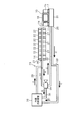
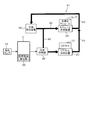
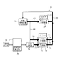
- FIG. 1 shows a first embodiment, and is a diagram schematically showing a cooling structure in an inverter device.
- FIG. 2 is a diagram schematically showing the configuration of the cooling device
- FIG. 3 is a flowchart showing a control procedure for the cooling suppressor
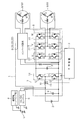
- FIG. 4 is a diagram schematically showing an overall circuit configuration of the power control unit.
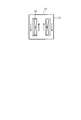
- FIG. 5 is a cross-sectional view schematically showing the reactor
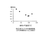
- FIG. 6A is a characteristic diagram showing temperature characteristics related to a magnetic core made of MnZn-based ferrite;
- FIG. 1 shows a first embodiment, and is a diagram schematically showing a cooling structure in an inverter device.
- FIG. 2 is a diagram schematically showing the configuration of the cooling device
- FIG. 3 is a flowchart showing a control procedure for the cooling suppressor
- FIG. 4 is a diagram schematically showing an overall circuit configuration of the power control unit.
- FIG. 5 is a cross-sectional view schematically showing the reactor
- FIG. 6A
- FIG. 6B is a characteristic diagram showing temperature characteristics of a magnetic core made of an Fe—Si—Al alloy
- FIG. 7A is a characteristic diagram showing temperature characteristics of an amorphous magnetic core alone
- FIG. 7B is a characteristic diagram showing temperature characteristics regarding a reactor using an amorphous magnetic core alone
- FIG. 8 shows the second embodiment and is a diagram schematically showing a cooling structure in the inverter device.
- FIG. 9 is a diagram schematically showing the configuration of the cooling device
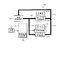
- FIG. 10 shows the third embodiment and is a diagram schematically showing a cooling structure in the inverter device.
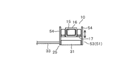
- FIG. 11 is a diagram schematically showing the configuration of the cooling suppressor part
- FIG. 12 is a diagram schematically showing a cooling structure in the inverter device according to the fourth embodiment.
- FIG. 13 shows a fifth embodiment, and is a diagram schematically showing a cooling structure in an inverter device.
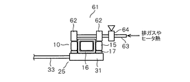
- FIG. 14 is a diagram schematically showing the configuration of the heating device portion
- FIG. 15 is a diagram schematically illustrating a cooling structure in the inverter device according to the sixth embodiment.
- FIG. 16 shows the seventh embodiment, and is a diagram schematically showing a cooling structure in the inverter device.
- FIG. 17 is a diagram schematically showing the structure of the cooling device for the reactor
- FIG. 18 is a diagram schematically illustrating a cooling structure in the inverter device according to the eighth embodiment.
- FIG. 4 schematically shows an overall circuit configuration of a hybrid vehicle drive device called a power control unit.
- This drive device includes an inverter device 1 as a power conversion device according to the present embodiment for driving a motor / generator.
- the hybrid vehicle is provided with two motor generators MG1 and MG2 for traveling and power generation, and a control device 3 for controlling the HV battery 2 for power source, the inverter device 1 and the like.
- a control device 3 for controlling the HV battery 2 for power source, the inverter device 1 and the like.
- Auxiliary equipment (on-vehicle electrical components) 4 such as a headlamp, an auxiliary battery 5, a DC-DC converter 6 for driving the auxiliary equipment, and the like are also provided.
- the voltage of the HV battery 2 is, for example, 201.6V
- the voltage of the auxiliary battery 5 is, for example, 12V.
- the DC-DC converter 6 converts the DC high voltage of the HV battery 2 into a low voltage (for example, 14 V), and supplies it to the auxiliary machinery 4 or charges the auxiliary battery 5.
- the inverter device 1 includes a boost converter 7 that boosts the voltage of the HV battery 2 to, for example, a maximum of 650V.
- the inverter device 1 includes two sets of three-phase inverter circuits 8 and 8 that convert the boosted DC voltage into three-phase AC and drive the motor generators MG1 and MG2.
- the boost converter 7 and the inverter circuits 8 and 8 are controlled by the control device 3.
- the boost converter 7 includes an input capacitor 9, a reactor 10, two switching elements 11 and 11 such as IGBTs, diodes 12 and 12 connected in reverse parallel to the switching elements 11 and 11, and an output capacitor 13. ing.
- the two sets of switching elements 11 and 11 and diodes 12 and 12 are configured as a semiconductor module 14 molded in a thin package.
- the package is provided with a cooling plate made of metal such as aluminum or copper on both sides or one side.
- the reactor 10 includes, for example, an EE type magnetic core 15 having two winding gaps and a coil 16 wound in adjacent winding gaps. Has been.
- a current is passed through the coil 16 in the direction shown in FIG. 5, a magnetic flux having a closed magnetic path as shown by an arrow in the figure is generated in the magnetic core 15.
- a pair of terminals of the coil 16 are drawn out and connected to other electric elements.
- the following can be employ
- a powder magnetic core, a powder or non-compact magnetic core made of amorphous Fe powder, a ferrite, a laminated iron core, or the like As schematically shown in FIG. 2, the bottom of the reactor 10 is thermally connected to a cooling plate 31 described later via an insulating layer 17 having a thickness of several ⁇ m to several mm.
- the insulating layer 17 is made of a heat radiation resin containing a filler that enhances thermal conductivity in the resin. It is good also as a structure which accommodates the reactor 10 in metal cases.
- the reactor 10 is provided with a temperature sensor 19 (see FIGS. 1 and 4) such as a thermistor for detecting the temperature inside the reactor 10.
- a temperature sensor 19 such as a thermistor for detecting the temperature inside the reactor 10.
- a sensor such as a thermocouple or a platinum resistance thermometer can be used.
- the temperature sensor 19 can be provided in the reactor 10 on the surface of the magnetic core 15, the inside of the magnetic core 15, the surface of the reactor 10 including the coil 16, and the inside of the reactor 10. Or it is good also as a structure which detects the temperature of the vicinity of the reactor 10 and estimates the reactor 10 temperature from there.
- each inverter circuit 8 includes six switching elements 20 such as IGBTs, and diodes 21 connected to the respective switching elements 20 in antiparallel.
- a circuit in which a parallel connection circuit of a switching element 20 and a diode 21 constituting upper and lower arms is connected in series is provided as a semiconductor module 22 (see FIG. 2).
- the semiconductor module 22 is configured by molding two sets of switching elements 20 and diodes 21 in a thin package.
- metal cooling plates are arranged on both sides or one side of the package.
- the inverter device 1 incorporates a boost converter 7 and inverter circuits 8 and 8 in a case (not shown), and a cooling mechanism 23 (see FIGS. 1 and 2) for cooling each component constituting them.
- the cooling mechanism 23 includes a module cooling device 24 that cools the semiconductor modules 14 and 22.
- the cooling mechanism 23 supplies a reactor cooling device 25 as a cooling device for cooling the reactor 10 and a refrigerant (for example, antifreeze) as a low-temperature cooling fluid to the module cooling device 24 and the reactor cooling device 25.
- a refrigerant supply device 26 for example, antifreeze
- the module cooling device 24 is composed of a well-known stacked type cooler. That is, as shown in FIG. 2, the module cooling device 24 includes a plurality of (eight in the drawing) cooling plates 27 arranged in parallel in the horizontal direction in the drawing.
- the cooling plate 27 is made of a metal such as aluminum in a hollow shape that is thin (flat) in the left-right direction in the figure, and a refrigerant inlet is provided on the rear end side in the figure.
- a refrigerant outlet is provided on the front end side in the figure.
- the inlet portion of each cooling plate 27 is connected to an inlet-side header portion that is located on the back side in the drawing and is long in the left-right direction in the drawing.
- the outlet portion of each cooling plate 27 is connected to an outlet-side header portion 28 that is located on the near side in the drawing and is long in the left-right direction in the drawing.
- the low-temperature refrigerant supplied from the refrigerant supply device 26 is supplied to the inlet side header portion through the first supply pipe 29 constituting the cooling path. Then, the refrigerant flows in each cooling plate 27 from the back side toward the front side in the drawing, and is discharged from the outlet side header portion 28 to the intermediate discharge pipe 30 constituting the cooling path.
- the semiconductor module 14 and the six semiconductor modules 22 are arranged in order from the left in the drawing. Thus, the semiconductor module 14 and each semiconductor module 22 are cooled by the module cooling device 24.
- the reactor cooling device 25 includes a cooling plate 31 that is a cooling member disposed in a thermal contact state with the bottom of the reactor 10.
- the cooling plate 31 is made of a metal such as aluminum into a thin hollow shape, and has a refrigerant inlet portion and an outlet portion for supplying and discharging the refrigerant therein.
- the refrigerant inlet on the back side is connected to the second supply pipe 32 constituting the cooling path, and the refrigerant is supplied from the second supply pipe 32 into the cooling plate 31.
- the 2nd discharge pipe 33 which comprises a cooling path
- the refrigerant supply device 26 includes a pump for circulating and supplying the refrigerant through a cooling path, and a heat exchanger (radiator) for cooling the high-temperature refrigerant.
- the cooling path is provided in a form in which the cooling path of the module cooling device 24 and the cooling path of the reactor cooling device 25 are connected. That is, as shown in FIG. 1, the refrigerant discharged from the refrigerant supply device 26 is supplied to the module cooling device 24 through the first supply pipe 29. The refrigerant discharged from the module cooling device 24 is supplied to the cooling suppressor 34 through the intermediate discharge pipe 30.
- the cooling suppressor 34 is composed of, for example, a switching valve having one inlet and first and second two outlets, and the fluid (refrigerant) entering from the inlet is first and second. It is configured to be switchable so as to selectively flow to either one of the outlets.
- the first outlet is connected to the intermediate return pipe 35
- the second outlet is connected to the second supply pipe 32.
- second state a state where the cooling suppressor 34 is switched to the second outlet side (this is referred to as “second state”), as indicated by arrows A and C in FIG.
- the refrigerant discharged from the intermediate discharge pipe 30 after being supplied is supplied to the reactor cooling device 25 through the second supply pipe 32.
- the refrigerant is configured to return to the refrigerant supply device 26 from the second discharge pipe 33. That is, the refrigerant is supplied to both the module cooling device 24 and the reactor cooling device 25, and both the semiconductor modules 14 and 22 and the reactor 10 are cooled.
- the cooling suppressor 34 is controlled to be switched by the control device 3.
- a detection signal of a temperature sensor 19 that detects the temperature of the reactor 10 is input to the control device 3.
- the control apparatus 3 has the target temperature calculation part 36 which determines the target temperature of the said reactor 10 mainly by the software structure.
- the target temperature is determined as follows. That is, the target temperature is the temperature around the temperature at which the loss is minimum, that is, the minimum point, from the heat resistance temperature of the reactor 10 and the temperature characteristics indicating the relationship between the temperature of the reactor 10 (the magnetic core 15 or the entire reactor 10) and power loss.
- the temperature is determined to be slightly lower than that.
- the heat-resistant temperature of the reactor 10 is determined from the heat-resistant temperature of the coating material of the coil 16, the Curie point of the magnetic core 15, the heat-resistant temperature of the binder material such as resin forming the magnetic core 15, and the like. However, if there is a component having a low heat resistant temperature around the reactor 10, the heat resistant temperature corresponding to the heat resistant temperature of the peripheral component is set.
- the control device 3 keeps the cooling suppressor 34 in the second state during normal operation.
- a predetermined temperature for example, 10 ° C.
- the temperature is quickly raised to the target temperature. Therefore, by switching the cooling suppressor 34 to the first state, the refrigerant flow to the reactor cooling device 25 is interrupted, that is, the cooling of the reactor 10 is suppressed.
- the temperature adjusting device of the reactor 10 according to the present embodiment is configured by the reactor cooling device 25, the cooling suppressor 34, the control device 3, and the like.
- the operation of the above configuration will be described with reference to FIGS. 3, 6A, 6B, 7A, and 7B.
- the relationship between the power loss of the reactor 10 and the temperature will be described.
- the magnetic circuit components such as the reactor 10 differ depending on the material of the magnetic core 15, but the temperature characteristics indicating the relationship between the temperature and the loss are compared with each other at a low temperature, for example, about 20 ° C. Become bigger.
- the loss tends to decrease as the temperature increases up to 100 ° C. (see, for example, Japanese Unexamined Patent Publication No. 2007-51052 and International Publication No. WO2011 / 016207A1). .
- FIG. 6A shows the temperature characteristics when the material of the magnetic core 15 is MnZn-based ferrite, that is, the loss ratio when the loss at 20 ° C. is 1. As the temperature rises from 20 ° C., the power loss decreases and there is a minimum loss near 100 ° C. In this case, if the heat resistant temperature of the reactor 10 is set to 150 ° C., the target temperature is determined to be 80 ° C., which is slightly lower than 100 ° C. which is the lowest point.
- FIG. 6B shows the temperature characteristics when the material of the magnetic core 15 is an Fe—Si—Al alloy, that is, the loss ratio when the loss at 20 ° C. is 1. In the case of this material, there is a minimum loss point around 120 ° C. Also in this case, if the heat resistant temperature of the reactor 10 is set to 150 ° C., the target temperature is determined to be 100 ° C., which is slightly lower than 120 ° C., which is the lowest point.
- FIGS. 7A and 7B show the case where the material of the magnetic core 15 is amorphous.
- FIG. 7A shows the relationship between the power loss and the temperature in the magnetic core 15 alone, that is, the loss ratio which is the temperature characteristic when the loss at 0 ° C. is 1. In the case of this amorphous magnetic core 15, there is not much change in loss due to temperature, and the magnetic core 15 alone hardly shows temperature dependence.
- FIG. 7B shows temperature characteristics when the reactor 10 in which the amorphous magnetic core 15 is sealed with an insulating layer such as an epoxy resin is incorporated in the case (loss ratio when loss at 30 ° C. is 1). Is shown. As the temperature increases from 30 ° C., the power loss decreases, and there is a minimum loss point near 80 ° C.
- the target temperature is determined to be 60 ° C., which is slightly lower than 80 ° C., which is the lowest point, in consideration of the heat-resistant temperature.
- the control apparatus 3 is making the switching valve of the cooling suppression device 34 into a 2nd state (2nd exit side) in normal time.
- the refrigerant is supplied to both the module cooling device 24 and the reactor cooling device 25.
- the cooling mechanism 23 cools the semiconductor modules 14 and 22 and the reactor 10 which are heat generating components.
- the control device 3 increases the temperature to the target temperature early.
- the cooling suppressor 34 is operated.
- the on-off valve is switched to the first state (first outlet side), and the refrigerant flow is switched to the direction indicated by arrows A and B in FIG. . Accordingly, the refrigerant is not supplied to the reactor cooling device 25, and the cooling of the reactor 10 is suppressed, that is, the temperature increase of the reactor 10 is promoted.
- step S1 the heat resistant temperature of the reactor 10, for example, 150 ° C. is set.
- step S2 the target temperature is calculated. As described above, this target temperature is a temperature lower than the heat-resistant temperature of the reactor 10, and is determined to be a temperature slightly lower than the lowest point of loss from the temperature characteristics of the magnetic core 15 alone or the entire reactor 10. .
- the target temperature when the material of the magnetic core 15 is MnZn-based ferrite, the target temperature can be set to 80 ° C. As shown in FIG. 6B, when the material of the magnetic core 15 is an Fe—Si—Al alloy, the target temperature can be set to 100 ° C. Furthermore, as shown in FIG. 7B, when the magnetic core 15 is made of an amorphous material, the target temperature can be set to 60 ° C.
- the temperature characteristics as shown in FIGS. 6A and 6B and FIGS. 7A and 7B are experimentally measured in advance, and the target temperature is calculated and determined after taking into consideration the heat resistance temperature of the reactor 10 or peripheral components. can do.
- step S3 it is determined whether or not the temperature of the reactor 10 detected by the temperature sensor 19 is equal to or lower than a predetermined temperature.
- the predetermined temperature is a predetermined temperature lower than the target temperature.
- the predetermined temperature is set to 10 ° C., for example, in consideration of the start of the vehicle in winter.
- cooling suppressor 34 does not operate and remains in the second state.
- coolant is supplied to both the module cooling device 24 and the reactor cooling device 25, and cooling of the semiconductor modules 14 and 22 and the reactor 10 is achieved.
- Step S3 when the temperature of the reactor 10 is equal to or lower than the predetermined temperature (Yes in Step S3), the cooling suppressor 34 is operated in Step S4 and switched to the first state. Thereby, the refrigerant is supplied only to the module cooling device 24 side and is not supplied to the reactor cooling device 25. Thus, cooling of the semiconductor modules 14 and 22 is continued, and the temperature of the reactor 10 is increased.
- Step S5 it is determined whether the temperature of the reactor 10 detected by the temperature sensor 19 has reached the target temperature or whether an abnormal operation has been detected.
- step S5 If the temperature of reactor 10 has not reached the target temperature, or if an abnormal operation is not detected (No in step S5), the process returns to step S4, and the operation (first state) of cooling suppressor 34 is continued.
- the process returns to step S4, and the operation (first state) of cooling suppressor 34 is continued.
- cooling suppressor 34 is returned to the normal second state, and the process ends. .
- the reactor 10 when the target temperature at which the power loss of the reactor 10 is reduced is determined and the temperature of the reactor 10 is equal to or lower than the predetermined temperature lower than the target temperature, the reactor 10 is cooled by the cooling suppressor 34. It was comprised so that the cooling of could be suppressed. As a result, the reactor 10 can be quickly raised to the target temperature. For example, at the start in winter, the temperature of the reactor 10 does not increase easily, and the loss is prevented from increasing. The power loss of the reactor 10 can be kept relatively low.
- the target temperature is set to a temperature slightly lower than the temperature at which the loss is minimized.
- the target temperature is set to the minimum point, the actual temperature of the reactor 10 exceeds the target temperature, and there is a possibility that the loss rapidly increases and thermal runaway occurs.
- the target temperature may be set near the minimum point if there is no problem near the minimum point even if the variation is taken into consideration as a result of the prior measurement.
- the present embodiment not only the relationship between the temperature and loss of the magnetic core 15 constituting the reactor 10 but also the temperature and loss of the reactor 10 as a whole when the material of the magnetic core 15 is amorphous.
- the target temperature was set using the relationship.
- the magnetic core 15 alone has no temperature dependency, when the magnetic core 15 is incorporated in the power conversion device as the reactor 10, the loss decreases as the temperature rises.
- the power loss of the reactor 10 can be kept low.
- a cooling path for circulating and supplying the refrigerant is connected in series. And it was comprised so that cooling of the reactor 10 might be suppressed by interrupting
- the refrigerant supply device 26 and a part of the cooling path can be shared between the reactor cooling device 25 and the module cooling device 24, and the cooling mechanism 23 can be configured with a relatively simple configuration.
- during the operation of the cooling suppressor 34 (first state) it is possible to improve the cooling efficiency for the semiconductor modules 14 and 22 by shortening the cooling path, in other words, to reduce the driving power of the refrigerant supply device 26 pump. .
- FIGS. 8 and 9 show a second embodiment.
- This second embodiment is different from the first embodiment in the configuration of the cooling path of the cooling mechanism 41 for cooling the semiconductor modules 14 and 22 and the reactor 10.
- the refrigerant from the refrigerant supply device 26 is flowed in series with respect to the module cooling device 24 and the reactor cooling device 25.
- the cooling mechanism 41 of the second embodiment is configured so that the refrigerant flows in parallel to the module cooling device 24 and the reactor cooling device 25.
- the refrigerant discharged from the refrigerant supply device 26 is supplied to the module cooling device 24 (inlet side header portion) through the first supply pipe 42 as shown by an arrow A in FIG.
- the discharged refrigerant is returned to the refrigerant supply device 26 through the first discharge pipe 43.
- a second supply pipe 44 is provided so as to branch from the middle of the first supply pipe 42, and the refrigerant is supplied to the reactor cooling device 25 through the second supply pipe 44 as indicated by an arrow C in FIG. 9.
- the refrigerant discharged from the reactor cooling device 25 joins the intermediate portion of the first discharge pipe 43 through the second discharge pipe 45 and is returned to the refrigerant supply device 26.
- a cooling suppressor 46 is provided in the middle of the second supply pipe 44.
- the cooling suppressor 46 is composed of an on-off valve that opens and closes the second supply pipe 44 and is controlled to be opened and closed by the control device 3. In a normal time, the cooling suppressor 46 is in an open state, and the refrigerant is supplied to both the module cooling device 24 and the reactor cooling device 25, and the circulation returning to the refrigerant supply device 26 is performed. And the control apparatus 3 has the target temperature calculation part 36 similarly to the said 1st Embodiment, and controls the cooling inhibitor 46. FIG. Thus, when the detected temperature of the reactor 10 detected by the temperature sensor 19 is a predetermined temperature lower than the target temperature, for example, 10 ° C. or less, the cooling suppressor 46 is configured to increase the temperature to the target temperature early. Be operated.
- the on-off valve of the cooling suppressor 46 is switched to the closed state, and the circulation of the refrigerant in the second supply pipe 44 is interrupted.
- the refrigerant is supplied only to the module cooling device 24, the semiconductor modules 14 and 22 are cooled, and no refrigerant is supplied to the reactor cooling device 25, so that the cooling of the reactor 10 is suppressed, that is, the reactor 10 Temperature rise is promoted. Therefore, also by this 2nd Embodiment, the effect
- FIG. 10 and FIG. 11 show a third embodiment.
- the configuration of the cooling mechanism 52 including the cooling suppressor 51 is different from that of the first embodiment. That is, in the present embodiment, as shown in FIG. 11, the cooling suppressor 51 includes a moving mechanism 53 that moves the reactor 10 in the contact / separation direction with respect to the cooling plate 31 of the reactor cooling device 25 and its drive source. It is configured.
- the reactor 10 is supported by the slide rail 54 so as to be movable in the vertical direction with respect to the cooling plate 31 in the drawing.
- the reactor 10 is moved by the moving mechanism 53 between a lowered position that contacts the cooling plate 31 and an elevated position that is physically separated from the cooling plate 31.
- the moving mechanism 53 can be configured with a motor, a solenoid, a hydraulic mechanism, or the like (not shown) as a drive source, and is controlled by a control device 3 having a target temperature calculation unit 36 as shown in FIG.
- the cooling mechanism 52 has a structure in which the intermediate return pipe 35 and the cooling suppressor 34 are removed from the cooling mechanism 23 (see FIG. 1) of the first embodiment. That is, the refrigerant discharged from the refrigerant supply device 26 is supplied to the module cooling device 24 (inlet side header portion), and the refrigerant discharged from the outlet side header portion 28 passes through the second supply pipe 55 in the reactor cooling device 25. It is supplied to the cooling plate 31. The refrigerant discharged from the cooling plate 31 is circulated back to the refrigerant supply device 26 through the second discharge pipe 33.
- the controller 3 normally places the reactor 10 in the lowered position, and the semiconductor modules 14 and 22 and the reactor 10 are cooled by the module cooling device 24 and the reactor cooling device 25. Then, similarly to the first embodiment, the control device 3 operates the cooling suppressor 51 when the detected temperature of the reactor 10 detected by the temperature sensor 19 is equal to or lower than a predetermined temperature lower than the target temperature. Then, the reactor 10 is moved to the raised position. As a result, the reactor 10 is separated from the cooling plate 31 and the cooling is suppressed, and the temperature is quickly raised to the target temperature. Therefore, also in the third embodiment, it is possible to obtain operations and effects such as that the power loss of the reactor 10 can be kept relatively low, as in the first embodiment. In addition, the intended purpose can be achieved with a relatively simple configuration.
- FIG. 12 shows the fourth embodiment.
- the difference from the third embodiment is the configuration of the cooling mechanism 56. That is, the cooling mechanism 56 of the fourth embodiment includes a cooling suppressor 51 similar to that of the third embodiment, instead of the cooling suppressor 46 (see FIG. 8) in the second embodiment. Yes.
- the refrigerant discharged from the refrigerant supply device 26 is supplied to the module cooling device 24 (inlet side header portion) through the first supply pipe 42. Then, the refrigerant discharged from the outlet side header portion 28 is returned to the refrigerant supply device 26 through the first discharge pipe 43.
- a second supply pipe 44 branched from the middle of the first supply pipe 42 is provided, and the refrigerant is supplied to the cooling plate 31 of the reactor cooling device 25 through the second supply pipe 44.
- the refrigerant discharged from the reactor cooling device 25 joins the intermediate portion of the first discharge pipe 43 through the second discharge pipe 45 and is returned to the refrigerant supply device 26.
- the control device 3 positions the reactor 10 in the lowered position during normal operation. Then, when the detected temperature of the reactor 10 detected by the temperature sensor 19 is equal to or lower than a predetermined temperature lower than the target temperature, the control device 3 operates the cooling suppressor 51 and moves the reactor 10 to the raised position. Suppresses cooling. Therefore, also in the fourth embodiment, similar to the first embodiment and the like, it is possible to obtain operations and effects such as that the power loss of the reactor 10 can be kept relatively low.
- FIG. 13 and FIG. 14 show a fifth embodiment.
- the fifth embodiment is different from the first embodiment in that a heating device 61 for heating the reactor 10 is provided in addition to providing the cooling mechanism 23.
- the heating device 61 includes, for example, a heating plate 62 formed in a hollow shape from aluminum or copper, a heat supply pipe 63 for supplying a heating medium to the heating plate 62, and the heat supply pipe.
- An on-off valve 64 provided in the middle of 63 is provided.
- the heating plate 62 is in thermal contact with the upper surface portion of the reactor 10 in the figure of the magnetic core 15.
- the heat supply pipe 63 is supplied with a heating medium having a high temperature using exhaust heat or combustion heat of the vehicle.
- the on-off valve 64 is closed. By opening the on-off valve 64, a high-temperature heating medium is supplied to the heating plate 62 through the heat supply pipe 63, and the magnetic core 15 of the reactor 10 is heated.
- the opening / closing valve 64 is controlled to be opened and closed by the control device 3.
- the control device 3 performs the same control as the first embodiment on the cooling suppressor 34 and controls the on-off valve 64 as follows. That is, in the normal time, the control device 3 sets the cooling suppressor 34 to the second state and closes the on-off valve 64. And the control apparatus 3 switches the cooling suppressor 34 to a 1st state, and stops supply of a refrigerant
- the cooling of the reactor 10 is suppressed (stopped), and the magnetic core 15 of the reactor 10 is forcibly heated, so that the temperature is increased more quickly to the target temperature.
- the cooling suppressor 34 is returned to the second state, and the on-off valve 64 is closed. Therefore, according to the fifth embodiment, in addition to the operation and effect of the first embodiment, the temperature increase up to the target temperature of the reactor 10 can be further promoted, and the power loss can be reduced. , Become more effective.
- exhaust heat or combustion heat of the vehicle is used as the heat source of the heating device 61, the exhaust heat can be effectively used.
- FIG. 15 shows a sixth embodiment.
- a cooling mechanism 41 similar to that of the second embodiment is provided, and a heating device 61 for heating the reactor 10 similar to that of the fifth embodiment is provided.
- the control device 3 sets the cooling suppressor 46 so that the temperature is increased to the target temperature early. Close. At the same time, the control device 3 opens the on-off valve 64 of the heating device 61.
- the temperature increase up to the target temperature of the reactor 10 can be further promoted, and it is more effective in reducing the power loss. Excellent effects such as can be obtained.
- FIGS. 16 and 17 show a seventh embodiment.
- the seventh embodiment is different from the first embodiment in the cooling path of the cooling mechanism 71, the configuration of the reactor cooling device 72, and the like.
- the reactor cooling device 72 includes a core cooling unit 73 for cooling the magnetic core 15 of the reactor 10 and a coil cooling unit 74 for cooling the coil 16.
- the core cooling unit 73 includes a cooling plate, which is a cooling member made of a metal such as aluminum, in a hollow shape and is in thermal contact with the bottom of the magnetic core 15.
- the coil cooling unit 74 includes a cooling plate that is a cooling member made of a metal such as aluminum in a hollow shape at the bottom of the coil 16 in a thermal contact state.
- the coil cooling unit 74 (cooling plate) is supplied with the refrigerant through the coil side supply pipe 75 and is discharged through the coil side discharge pipe 76.
- the core cooling unit 73 is supplied with the refrigerant through the core side supply pipe 77 and is discharged through the core side discharge pipe 78.
- a cooling suppressor 79 including an on-off valve is provided in the middle of the core side supply pipe 77.
- the refrigerant discharged from the refrigerant supply device 26 is supplied to the module cooling device 24 through the first supply pipe 29 and used for cooling the semiconductor modules 14 and 22.
- the refrigerant discharged from the module cooling device 24 is discharged through the intermediate discharge pipe 30.
- the coil side supply pipe 75 and the core side supply pipe 77 are connected so as to branch into two from the intermediate discharge pipe 30.
- the distal end of the coil side discharge pipe 76 is connected to the refrigerant supply device 26, and the distal end of the core side discharge pipe 78 is connected to the middle part of the coil side discharge pipe 76.
- the refrigerant that has passed through the intermediate discharge pipe 30 is supplied to the coil cooling unit 74 through the coil side supply pipe 75.
- it is supplied to the core cooling section 73 through the core side supply pipe 77, and both the coil 16 and the magnetic core 15 of the reactor 10 are cooled.
- the refrigerant contributing to the cooling is returned to the refrigerant supply device 26 through the coil side discharge pipe 76 and the core side discharge pipe 78.
- the refrigerant that has passed through the intermediate discharge pipe 30 is supplied to the coil cooling section 74 through the coil side supply pipe 75 to cool the coil 16.
- the flow of the refrigerant in the core-side supply pipe 77 is interrupted and is not supplied to the core cooling unit 73, and cooling of the magnetic core 15 is suppressed.
- the refrigerant is returned to the refrigerant supply device 26 through the coil side discharge pipe 76.
- the cooling suppressor 79 is controlled to open and close by the control device 3.
- the control device 3 keeps the cooling suppressor 79 open in a normal state, and the semiconductor modules 14 and 22 and the reactor 10 are cooled by the module cooling device 24 and the reactor cooling device 72.
- both the magnetic core 15 and the coil 16 of the reactor 10 are cooled by supplying the refrigerant to both the core cooling unit 73 and the coil cooling unit 74.
- the control device 3 operates the cooling suppressor 79 to close the on-off valve.
- the reactor cooling device 72 the refrigerant is supplied to the coil cooling unit 74, and the refrigerant supply to the core cooling unit 73 is stopped.
- the reactor 10 there is a situation in which the power loss increases at a low temperature with respect to the magnetic core 15, but it is desirable to cool the coil 16 because the resistance value increases and the loss increases at a high temperature.
- the present embodiment even when the temperature of the reactor 10 is equal to or lower than the predetermined temperature, cooling of only the magnetic core 15 in the reactor 10 is suppressed, and the coil 16 is cooled. Thereby, while the temperature rise of the coil 16 is suppressed, the temperature of the magnetic core 15 is quickly raised to the target temperature. Therefore, according to the seventh embodiment, by providing the core cooling unit 73 and the coil cooling unit 74 and individually controlling them, the loss can be further reduced and the efficiency can be increased.
- FIG. 18 shows the eighth embodiment, and the difference from the seventh embodiment is the configuration of the refrigerant flow path of the cooling mechanism 81.
- the reactor cooling device 72 having the core cooling unit 73 and the coil cooling unit 74 is provided, and the cooling suppressor 79 allows the refrigerant to flow therethrough. Be controlled.
- the refrigerant discharged from the refrigerant supply device 26 is supplied to the module cooling device 24 through the first supply pipe 42 and returned to the refrigerant supply device 26 through the first discharge pipe 43.
- a second supply pipe 44 is provided so as to branch from the middle of the first supply pipe 42, and a coil side supply pipe 75 and a core side supply pipe 77 are branched from the second supply pipe 44 into two. Is connected.
- a cooling suppressor 79 is provided in the middle of the core side supply pipe 77.
- the tip of the core side discharge pipe 78 is connected to the middle part of the coil side discharge pipe 76, and the tip of the coil side discharge pipe 76 is connected to the middle part of the first discharge pipe 43.
- a cooling suppression device reduces a refrigerant
- the cooling method is not limited to the circulation of the refrigerant, and may be an air-cooling type in which cooling air is supplied by a fan or the like. In this case, the cooling air is blocked and the flow rate is reduced to suppress the cooling. Can do.
- a dedicated heater may be provided.
- the present invention is applied to an inverter device for a hybrid vehicle.
- the power conversion device may be a device that converts power into DC-DC, a device that converts AC-AC, or the like.
- the magnetic circuit component is not limited to the reactor of the boost converter, but can also be applied to a PFC reactor mounted on a charger, a smoothing choke, a transformer component of an insulating converter, and the like.
- the detailed configuration such as the specific configuration of the cooling device and the cooling path can be variously modified in addition to the above.
Landscapes
- Engineering & Computer Science (AREA)
- Power Engineering (AREA)
- Microelectronics & Electronic Packaging (AREA)
- Physics & Mathematics (AREA)
- Thermal Sciences (AREA)
- Inverter Devices (AREA)
- Dc-Dc Converters (AREA)
- Transformer Cooling (AREA)
- Housings And Mounting Of Transformers (AREA)
Abstract
電力変換装置(1)に組込まれ、磁性コア(15)と、この磁性コア(15)に巻装されたコイル(16)とを含む磁気回路部品(10)の、温度を調整するための磁気回路部品の温度調整装置は、前記磁気回路部品(10)を冷却するための冷却装置(25,72)と、前記磁気回路部品(10)の温度を推定する温度推定装置(19)と、前記磁気回路部品(10)の温度と損失との関係から損失が小さくなる目標温度を決定する目標温度決定装置(36)と、前記温度推定装置(19)が推定した前記磁気回路部品(10)の温度が、前記目標温度よりも低い所定温度以下であったときに、前記目標温度となるように前記冷却装置(25)による該磁気回路部品の冷却を抑制する冷却抑制装置(34,46,51,79)とを備える。
Description
本出願は、2016年3月17日に出願された日本出願番号2016-053787号に基づくもので、ここにその記載内容を援用する。
本開示は、電力変換装置に組込まれ、磁性コアとこの磁性コアに巻装されたコイルとを含む磁気回路部品の、温度を調整するための磁気回路部品の温度調整装置に関する。
例えば、駆動源として内燃機関と電気モータとの両方を有するハイブリッド自動車や、駆動源として電気モータを備えた自動車等では、電気モータを駆動制御するパワーコントロールユニットと称される駆動装置が搭載される。この種のパワーコントロールユニットとしては、ケース内に、大容量のインバータ装置やDC-DCコンバータといった電力変換装置を組込んで構成されるものがある(例えば特許文献1参照)。
このとき、電力変換装置を構成する部品のうち、特に、スイッチング素子を含むパワーモジュールやリアクトルといった発熱源となる部品を冷却するための冷却装置が設けられる。そのような冷却装置として、特許文献1では、複数個のパワーモジュールを挟むように設けられる積層型の第1冷却器と、リアクトルに添接される第2冷却器とを設ける構成が開示されている。この構成では、冷媒供給装置から、配管を通して冷媒(水)を第1冷却器に導入し、第1冷却器から排出された冷媒を第2冷却器に導入し、第2冷却器から排出された冷媒を冷媒供給装置に戻すという循環を行わせるようになっている。
ところで、磁気回路部品としてのリアクトルを構成する磁性コアにあっては、フェライト系、Fe-Si-Al合金系、アモルファス系等の各種の材料が採用されるが、材質による相違はあるものの、温度によって電力損失が変動することが知られている。近年の研究においては、低温度でリアクトルの損失が大きくなり、耐熱温度よりもやや低い、80~100℃程度で、損失が最低となることが指摘されてきている。
そのため、例えば冬季における始動時などにおいては、リアクトルの温度が10℃以下となっていることがあり、そのような低温では電力損失が比較的大きく、むしろ早く昇温させた方が、損失低減の面で有利となる。つまり、磁気回路部品の磁性コアについては、低温時においては、冷却を行わずに、むしろ昇温を図った方が、効率が良くなることになる。しかし、特許文献1の冷却装置にあっては、パワーモジュール及びリアクトルに対して、冷却が常に同様に行われるため、リアクトルの電力損失が大きい状態で運転されてしまうことが起こっていた。
本開示は、磁気回路の電力損失を比較的低く抑えることができる磁気回路部品の温度調整装置を提供することを目的とする。
本開示の第一の態様において、電力変換装置に組込まれ、磁性コアと、この磁性コアに巻装されたコイルとを含む磁気回路部品の、温度を調整するための磁気回路部品の温度調整装置であって、前記磁気回路部品を冷却するための冷却装置と、前記磁気回路部品の温度を推定する温度推定装置と、前記磁気回路部品の温度と損失との関係から損失が小さくなる目標温度を決定する目標温度決定装置と、前記温度推定装置が推定した前記磁気回路部品の温度が、前記目標温度よりも低い所定温度以下であったときに、前記目標温度となるように前記冷却装置による該磁気回路部品の冷却を抑制する冷却抑制装置とを備える。
ここで、磁気回路部品においては、磁性コアの材質により相違するが、温度と損失との関係を示す温度特性は、低温において損失が比較的大きくなり、耐熱温度よりもやや低い、例えば80~100℃程度で、損失が最低となる(図6A、図6B参照)。
上記構成によれば、電力変換装置に組込まれた磁気回路部品は、冷却装置によって冷却される。このとき、目標温度決定装置により、損失が小さくなる目標温度が決定される。温度推定装置により推定された磁気回路部品の温度が、前記目標温度よりも低い所定温度以下であったときに、前記目標温度となるように、冷却抑制装置により冷却装置による冷却が抑制される。
従って、冷却が抑制されることによって、目標温度までの上昇が速やかに行われるようになり、この結果、磁気回路の電力損失を比較的低く抑えることができる。
本開示についての上記目的およびその他の目的、特徴や利点は、添付の図面を参照しながら下記の詳細な記述により、より明確になる。その図面は、
図1は、第1の実施形態を示すものであり、インバータ装置における冷却構造を模式的に示す図であり、
図2は、冷却装置の構成を概略的に示す図であり、
図3は、冷却抑制器に対する制御手順を示すフローチャートであり、
図4は、パワーコントロールユニットの全体的な回路構成を概略的に示す図であり、
図5は、リアクトルを概略的に示す断面図であり、
図6Aは、MnZn系フェライトからなる磁性コアに関する温度特性を示す特性図であり、
図6Bは、Fe-Si-Al合金からなる磁性コアに関する温度特性を示す特性図であり、
図7Aは、アモルファス系磁性コア単体に関する温度特性を示す特性図であり、
図7Bは、アモルファス系磁性コア単体を用いたリアクトル)に関する温度特性を示す特性図であり、
図8は、第2の実施形態を示すもので、インバータ装置における冷却構造を模式的に示す図であり、
図9は、冷却装置の構成を概略的に示す図であり、
図10は、第3の実施形態を示すもので、インバータ装置における冷却構造を模式的に示す図であり、
図11は、冷却抑制器部分の構成を概略的に示す図であり、
図12は、第4の実施形態におけるインバータ装置における冷却構造を模式的に示す図であり、
図13は、第5の実施形態を示すもので、インバータ装置における冷却構造を模式的に示す図であり、
図14は、加熱装置部分の構成を概略的に示す図であり、
図15は、第6の実施形態におけるインバータ装置における冷却構造を模式的に示す図であり、
図16は、第7の実施形態を示すもので、インバータ装置における冷却構造を模式的に示す図であり、
図17は、リアクトルに対する冷却装置の構造を概略的に示す図であり、
図18は、第8の実施形態におけるインバータ装置における冷却構造を模式的に示す図である。
(1)第1の実施形態
以下、第1の実施形態について、図1~図7Bを参照しながら説明する。尚、以下に述べる各実施形態では、本開示を、ハイブリッド車に搭載されるインバータ装置に適用したものである。図4は、パワーコントロールユニットと称されるハイブリッド車の駆動装置の全体的な回路構成を概略的に示している。この駆動装置は、モータ・ジェネレータ駆動用の、本実施形態に係る電力変換装置としてのインバータ装置1を含んでいる。
以下、第1の実施形態について、図1~図7Bを参照しながら説明する。尚、以下に述べる各実施形態では、本開示を、ハイブリッド車に搭載されるインバータ装置に適用したものである。図4は、パワーコントロールユニットと称されるハイブリッド車の駆動装置の全体的な回路構成を概略的に示している。この駆動装置は、モータ・ジェネレータ駆動用の、本実施形態に係る電力変換装置としてのインバータ装置1を含んでいる。
ここで、ハイブリッド車には、走行用及び発電用の2個のモータ・ジェネレータMG1、MG2が設けられていると共に、動力源用のHVバッテリ2、前記インバータ装置1等を制御する制御装置3が設けられている。また、ヘッドランプ等の補機類(車載電装品)4、補機用バッテリ5、補機駆動用のDC-DCコンバータ6等も設けられている。尚、前記HVバッテリ2の電圧は、例えば201.6Vとされ、前記補機用バッテリ5の電圧は、例えば12Vとされている。DC-DCコンバータ6は、前記HVバッテリ2の直流高電圧を、低電圧(例えば14V)に変換し、補機類4に供給したり、補機用バッテリ5に充電したりするものである。
前記インバータ装置1は、前記HVバッテリ2の電圧を、例えば最大650Vに昇圧する昇圧コンバータ7を備えている。これと共に、インバータ装置1は、昇圧された直流電圧を三相交流に変換して前記各モータ・ジェネレータMG1、MG2を駆動する2組の三相のインバータ回路8、8を備えている。それら昇圧コンバータ7及びインバータ回路8、8は、前記制御装置3により制御される。
そのうち、前記昇圧コンバータ7は、入力コンデンサ9、リアクトル10、2個のIGBT等のスイッチング素子11,11、それらスイッチング素子11,11に夫々逆並列接続されたダイオード12,12、出力コンデンサ13を備えている。このとき、図2にも示すように、2組のスイッチング素子11,11及びダイオード12,12は、薄型パッケージ内にモールドされた半導体モジュール14として構成されている。詳しく図示はしないが、このパッケージには、両面又は片面に位置して、アルミ、銅等の金属製の冷却プレートが配置されている。
図5、図2に示すように、前記リアクトル10は、例えば、2個の巻回隙間を有するEE型の磁性コア15と、隣り合う巻回隙間に巻回されたコイル16とを備えて構成されている。前記コイル16に対し、図5に示す方向に電流を通電すると、磁性コア15には、図に矢印で示すような閉磁路をもつ磁束が発生する。図示はしないが、コイル16の一対の端子が外部に引出され、他の電気素子と接続されている。
尚、前記磁性コア15の材質としては、次のようなものを採用することができる。例えば、Fe-Si合金、Fe-Si-Al合金、Feのアモルファス、Fe-Si合金の粉からなる圧粉または非圧粉の磁心、Fe-Si-Al合金の粉からなる圧粉または非圧粉の磁心、Feのアモルファスの粉からなる圧粉または非圧粉の磁心、フェライト、又は積層鉄心などを採用することができる。また、図2に模式的に示すように、リアクトル10の底部は、数μmから数mm程度の厚みの絶縁層17を介して、後述する冷却プレート31に熱的に接続されている。前記絶縁層17は、樹脂内に熱伝導性を高めるフィラーを含む放熱樹脂から構成されている。リアクトル10を金属製のケース内に収容する構成としても良い。
そして、リアクトル10には、該リアクトル10の内部の温度を検出するための例えばサーミスタ等の温度センサ19(図1、図4参照)が設けられている。温度センサ19としては、サーミスタ以外でも、熱伝対、白金測温抵抗体などのセンサを利用することができる。温度センサ19は、リアクトル10のうち、磁性コア15の表面、磁性コア15の内部、コイル16を含むリアクトル10の表面、リアクトル10の内部、に設けることができる。或いは、リアクトル10の近傍の温度を検出し、そこからリアクトル10温度を推定する構成としても良い。
前記各インバータ回路8は、周知のように、6個のIGBT等のスイッチング素子20と、それら各スイッチング素子20に夫々逆並列接続されたダイオード21とを有して構成されている。このとき、U、V、Wの各相に関し、上下アームを構成するスイッチング素子20とダイオード21との並列接続回路を直列接続した回路が、半導体モジュール22(図2参照)として供される。詳しい図示は省略するが、半導体モジュール22は、2組のスイッチング素子20及びダイオード21を薄型のパッケージ内にモールドして構成される。これと共に、パッケージの両面又は片面に金属製の冷却プレートを配して構成されている。
さて、前記インバータ装置1は、図示しないケース内に、昇圧コンバータ7及びインバータ回路8、8を組込むと共に、それらを構成する各部品を冷却するための冷却機構23(図1、図2参照)を組込んでユニット化されている。図1、図2に示すように、本実施形態では、冷却機構23は、前記各半導体モジュール14,22を冷却するモジュール冷却装置24を含んでいる。さらに、冷却機構23は、前記リアクトル10を冷却するための冷却装置たるリアクトル冷却装置25と、それらモジュール冷却装置24及びリアクトル冷却装置25に対して低温の冷却流体としての冷媒(例えば不凍液)を供給する冷媒供給装置26とを含む。
そのうちモジュール冷却装置24は、周知の積層型冷却器から構成されている。即ち、図2に示すように、モジュール冷却装置24は、図で左右方向に並んで並列配置される複数個(図で8個)の冷却プレート27を備えている。詳しく図示はしないが、冷却プレート27は、アルミニウム等の金属から、図で左右方向に薄型(偏平)の中空状に構成されており、その図で後端部側に、冷媒の入口部が設けられると共に、図で前端部側に、冷媒の出口部が設けられている。各冷却プレート27の入口部は、図で奥側に位置して図で左右方向に長い入口側ヘッダ部に接続されている。また、各冷却プレート27の出口部は、図で手前側に位置して図で左右方向に長い出口側ヘッダ部28に接続されている。
後述するように、冷媒供給装置26から供給される低温の冷媒は、冷却経路を構成する第1供給管29を通して入口側ヘッダ部に供給される。そして、その冷媒は、各冷却プレート27内を図で奥側から手前に向けて流れ、出口側ヘッダ部28から、冷却経路を構成する中間排出管30に対して排出される。各冷却プレート27同士間のなす7つの空間部に、図で左から順に、半導体モジュール14、6個の半導体モジュール22が夫々配置されている。これにて、モジュール冷却装置24により半導体モジュール14及び各半導体モジュール22が冷却される。
これに対し、前記リアクトル冷却装置25は、前記リアクトル10の底部に熱的接触状態で配置された冷却部材たる冷却プレート31を備えている。この冷却プレート31は、アルミニウム等の金属から、薄型の中空状に構成されており、その内部に冷媒を供給、排出するための冷媒入口部及び出口部を有している。図で奥側の冷媒入口部は、冷却経路を構成する第2供給管32に接続され、第2供給管32から冷却プレート31内に冷媒が供給される。そして、図で手前側の冷媒出口部に、冷却経路を構成する第2排出管33が接続され、冷却プレート31内から冷媒が排出される。
前記冷媒供給装置26は、詳しく図示はしないが、冷媒を、冷却経路を通して循環供給させるためのポンプや、高温の冷媒を冷却するための熱交換器(ラジエータ)を備えている。本実施形態では、冷却経路は、モジュール冷却装置24の冷却経路とリアクトル冷却装置25の冷却経路とを接続した形態で設けられている。即ち、図1にも示すように、冷媒供給装置26から吐出された冷媒は、第1供給管29を通して、モジュール冷却装置24に供給される。モジュール冷却装置24から排出された冷媒は、中間排出管30を通して冷却抑制器34に供給される。
この冷却抑制器34は、この場合、例えば1個の入口と、第1及び第2の2個の出口とを有する切替弁からなり、入口から入った流体(冷媒)を第1、第2のどちらか一方の出口に選択的に流すように切替え可能に構成されている。例えば、第1の出口は、中間戻り管35に接続されており、第2の出口は、前記第2供給管32に接続されている。これにて、冷却抑制器34が第1の出口側に切替えられている状態(これを「第1状態」という)では、図2に矢印A、矢印Bで示すように、モジュール冷却装置24に供給された後の中間排出管30からの冷媒が、そのまま冷媒供給装置26に戻されるように構成されている。つまり、モジュール冷却装置24にのみ冷媒が供給され、各半導体モジュール14,22が冷却される。
これに対し、冷却抑制器34が第2の出口側に切替えられている状態(これを「第2状態」という)では、図2に矢印A、矢印Cで示すように、モジュール冷却装置24に供給された後の中間排出管30から排出された冷媒が、第2供給管32を通してリアクトル冷却装置25に供給される。その後、冷媒は、第2排出管33から冷媒供給装置26に戻されるように構成されている。つまり、冷媒は、モジュール冷却装置24及びリアクトル冷却装置25の双方に供給され、各半導体モジュール14,22並びにリアクトル10の双方が冷却される。
このとき、冷却抑制器34は、前記制御装置3により切替え制御される。制御装置3には、前記リアクトル10の温度を検出する温度センサ19の検出信号が入力されるようになっている。そして、制御装置3は、主としてそのソフトウエア的構成により、前記リアクトル10の目標温度を決定する目標温度算出部36を有している。
詳しくは次の作用説明にて述べるように、目標温度は次のように決定される。即ち、目標温度はリアクトル10の耐熱温度、及び、リアクトル10(磁性コア15、或いはリアクトル10全体)の温度と電力損失との関係を示す温度特性から、損失が最小となる温度付近、即ち最小点よりもやや低い温度に決定される。尚、リアクトル10の耐熱温度は、コイル16の被膜や、磁性コア15のキュリー点、磁性コア15成形している樹脂等のバインダ材の耐熱温度等から決定される。但し、リアクトル10の周辺に耐熱温度が低い部品があれば、その周辺部品の耐熱温度に応じた耐熱温度が設定される。
そして、制御装置3は、通常時には、前記冷却抑制器34を第2状態にしている。この場合、温度センサ19により検出したリアクトル10の検出温度が、目標温度よりも低い所定温度(例えば10℃)以下であるときに、目標温度まで早期に温度上昇させるようにする。そのために、前記冷却抑制器34を第1状態に切替えることで、リアクトル冷却装置25に対する冷媒の流通を遮断する、つまりリアクトル10の冷却を抑制するようになっている。これにて、リアクトル冷却装置25や冷却抑制器34、制御装置3等から、本実施形態に係るリアクトル10の温度調整装置が構成されている。
次に、上記構成の作用について、図3、図6A、図6B、図7A、図7Bも参照して述べる。ここでまず、リアクトル10の電力損失と温度との関係について述べる。図6A、Bに示すように、リアクトル10等の磁気回路部品においては、磁性コア15の材質により相違するが、温度と損失との関係を示す温度特性は、低温例えば20℃程度において損失が比較的大きくなる。そして、例えば100℃までの間で、温度が高くなるにつれ、損失が低減する傾向を示すことが知られている(例えば、日本国特開2007-51052号公報、国際公開WO2011/016207A1公報参照)。
図6Aは、磁性コア15の材質が、MnZn系フェライトの場合の、温度特性、つまり20℃における損失を1とした場合の損失比を示している。20℃から温度が上昇するにつれ、電力損失が低下し、100℃付近に損失の最低点が存在する。この場合、リアクトル10の耐熱温度が150℃と設定されているとすると、目標温度が、最低点である100℃よりもやや低い80℃に決定される。
また、図6Bは、磁性コア15の材質が、Fe-Si-Al合金の場合の、温度特性、つまり20℃における損失を1とした場合の損失比を示している。この材質の場合には、120℃付近に損失の最低点が存在する。この場合も、リアクトル10の耐熱温度が150℃と設定されているとすると、目標温度が、最低点である120℃よりもやや低い100℃に決定される。
これに対し、図7A、Bは、磁性コア15の材質が、アモルファス系の場合を示している。図7Aは、磁性コア15単体における電力損失と温度との関係、つまり0℃における損失を1とした場合の温度特性である損失比を示している。このアモルファス系の磁性コア15の場合、温度による損失にあまり変化はなく、磁性コア15単体では温度依存性はほとんど見られない。
ところが、本発明者の研究によれば、アモルファス系コアの場合、磁性コア15単体では、電力損失に温度依存性がなくても、リアクトル10としてインバータ装置1(ユニット)に組込んだ場合に、温度上昇に応じて損失が減少する現象が見られた.図7Bは、アモルファス系の磁性コア15を例えばエポキシ樹脂等の絶縁層で封止したリアクトル10を、ケース内に組込んだ場合の温度特性(30℃における損失を1とした場合の損失比)を示している。30℃から温度が上昇するにつれ、電力損失が低下し、80℃付近に損失の最低点が存在する。
このような現象が生ずる理由としては、磁性コア15を封止する絶縁樹脂の硬化収縮時や、リアクトル10の固定時において、磁性コア15に応力が印加され、ヤング率が高い低温時においては、残存する応力によって磁性コア15に歪みが生じて損失が大きくなる。ところが、温度上昇に伴い、ヤング率が低くなり、磁性コア15にかかる応力が緩和されることによって、損失が減少するものと推測される。このような場合にも、やはり耐熱温度を考慮して、目標温度が、例えば最低点である80℃よりもやや低い60℃に決定される。
さて、インバータ装置1が動作されると、制御装置3は、通常時においては、冷却抑制器34の切替弁を第2状態(第2の出口側)にしている。このとき、図2に矢印A、矢印Cに示すように、冷媒が、モジュール冷却装置24及びリアクトル冷却装置25の双方に供給される。これにて、冷却機構23により、発熱部品である半導体モジュール14,22並びにリアクトル10の冷却が図られる。
これに対し、制御装置3は、温度センサ19により検出したリアクトル10の検出温度が、目標温度よりも低い所定温度(例えば10℃)以下であるときに、目標温度まで早期に温度上昇させるように、前記冷却抑制器34を動作させる。これにより、開閉弁が第1状態(第1の出口側)に切替えられ、冷媒の流れが、図2に矢印A、矢印Bで示す方向、つまりリアクトル冷却装置25を通らない循環形態に切替えられる。従って、リアクトル冷却装置25に冷媒が供給されなくなり、リアクトル10の冷却が抑制される、つまりリアクトル10の温度上昇が促進されるようになる。
図3のフローチャートは、制御装置3が実行する、リアクトル10に対する温度調整、つまり冷却抑制器34の弁の切替えに関する制御手順を示している。即ち、ステップS1では、リアクトル10の耐熱温度、例えば150℃が設定される。次のステップS2では、目標温度が算出される。この目標温度は、上記したように、リアクトル10の耐熱温度よりも低い温度であり、且つ、磁性コア15単体或いはリアクトル10全体の温度特性から、損失の最低点よりもやや低い温度に決定される。
具体例を上げると、図6Aに示したように、磁性コア15の材質がMnZn系フェライトの場合には、目標温度を80℃とすることができる。図6Bに示したように、磁性コア15の材質がFe-Si-Al合金の場合には、目標温度を100℃とすることができる。更に、図7Bに示したように、磁性コア15の材質がアモルファス系の場合には、目標温度を60℃とすることができる。図6A、B及び図7A、Bに示したような温度特性を、事前に実験的に測定しておき、リアクトル10或いは周辺部品の耐熱温度を考慮に入れた上で、目標温度を算出・決定することができる。
図3に戻って、ステップS3では、前記温度センサ19が検出したリアクトル10の温度が、所定温度以下かどうかが判断される。所定温度とは、目標温度よりも低い所定温度であり、この場合、冬季における車両の始動時等を考慮して、例えば10℃に設定される。リアクトル10の温度が、所定温度を超えている場合には(ステップS3にてNo)、冷却抑制器34は動作せず、第2状態のままとされる。これにより、上記のように、冷媒が、モジュール冷却装置24及びリアクトル冷却装置25の双方に供給され、半導体モジュール14,22並びにリアクトル10の冷却が図られる。
これに対し、リアクトル10の温度が、所定温度以下の場合には(ステップS3にてYes)、ステップS4にて、冷却抑制器34を動作させ、第1状態に切替えられる。これにより、冷媒が、モジュール冷却装置24側にのみ供給され、リアクトル冷却装置25に供給されなくなる。これにて、各半導体モジュール14,22に対する冷却は継続される一方、リアクトル10の温度上昇が図られる。次のステップS5では、温度センサ19が検出したリアクトル10の温度が目標温度に達したか、又は異常動作が検出されたかどうかが判断される。
リアクトル10の温度が目標温度にまで達していない場合、或いは異常動作が検出されない場合には(ステップS5にてNo)、ステップS4に戻り、冷却抑制器34の動作(第1状態)が継続される。そして、リアクトル10の温度が目標温度に達した場合,或いは異常動作が検出された場合には(ステップS5にてYes)、冷却抑制器34が通常の第2状態に戻され、処理が終了する。
このように本実施形態によれば、リアクトル10の電力損失が小さくなる目標温度が決定され、リアクトル10の温度が、前記目標温度よりも低い所定温度以下であるときには、冷却抑制器34によりリアクトル10の冷却を抑制するように構成した。これにより、リアクトル10の目標温度までの上昇が速やかに行われるようになり、例えば冬季の始動時などにおいて、リアクトル10の温度がなかなか上昇せずに、損失が大きくなってしまうことを防止し、リアクトル10の電力損失を比較的低く抑えることができる。
また、本実施形態では、目標温度を、損失が最小となる温度よりもやや低い温度に設定するようにした。ここで、目標温度を最小点に設定してしまうと、実際のリアクトル10の温度が、その目標温度を超えてしまい、損失が急激に増加して熱暴走する虞がある。ところが、本実施形態のように目標温度を最小点よりもやや低い温度に設定することにより、そのような不具合を防止することができる。もちろん事前測定した結果、ばらつきを考慮しても最小点付近で不具合が無い場合は目標温度を最小点付近に設定しても良い。
特に本実施形態では、リアクトル10を構成する磁性コア15単体における温度と損失との関係を利用するだけでなく、磁性コア15の材質がアモルファスの場合において、リアクトル10全体としての温度と損失との関係を利用して、目標温度を設定するようにした。これにより、磁性コア15単体では、電力損失に温度依存性がない場合でも、リアクトル10として電力変換装置に組込んだ場合に、温度上昇に応じて損失が減少する関係を利用して、同様に、リアクトル10の電力損失を低く抑えることができる。
更に、本実施形態では、リアクトル冷却装置25及びモジュール冷却装置24(冷却機構23)の具体的構成として、冷媒を循環供給するための冷却経路を直列につないだ。そして、切替弁からなる冷却抑制器34により、リアクトル冷却装置25側への冷媒の流通を遮断することにより、リアクトル10の冷却を抑制するように構成した。これにより、冷媒供給装置26や冷却経路の一部を、リアクトル冷却装置25とモジュール冷却装置24との間で共用でき、比較的簡単な構成により、冷却機構23を構成することができる。また、冷却抑制器34の動作時(第1状態)においては、冷却経路の短縮による半導体モジュール14,22に対する冷却効率の向上、言い換えれば冷媒供給装置26ポンプの駆動電力の低減を図ることができる。
(2)第2の実施形態
図8及び図9は、第2の実施形態を示している。この第2の実施形態が、上記第1の実施形態と異なるところは、半導体モジュール14,22並びにリアクトル10を冷却するための、冷却機構41の冷却経路の構成にある。上記第1の実施形態では、モジュール冷却装置24及びリアクトル冷却装置25に対し、冷媒供給装置26からの冷媒をいわば直列に流すようにしていた。ところが、この第2の実施形態の冷却機構41では、モジュール冷却装置24及びリアクトル冷却装置25に対しいわば並列に冷媒を流すように構成されている。
図8及び図9は、第2の実施形態を示している。この第2の実施形態が、上記第1の実施形態と異なるところは、半導体モジュール14,22並びにリアクトル10を冷却するための、冷却機構41の冷却経路の構成にある。上記第1の実施形態では、モジュール冷却装置24及びリアクトル冷却装置25に対し、冷媒供給装置26からの冷媒をいわば直列に流すようにしていた。ところが、この第2の実施形態の冷却機構41では、モジュール冷却装置24及びリアクトル冷却装置25に対しいわば並列に冷媒を流すように構成されている。
即ち、冷媒供給装置26から吐出された冷媒は、図9に矢印Aで示すように、第1供給管42を通して、モジュール冷却装置24(入口側ヘッダ部)に供給され、出口側ヘッダ部28から排出された冷媒は、第1排出管43を通して冷媒供給装置26に戻される。前記第1供給管42の途中から分岐するようにして、第2供給管44が設けられ、図9に矢印Cで示すように、冷媒がこの第2供給管44を通してリアクトル冷却装置25に供給される。リアクトル冷却装置25から排出される冷媒は、第2排出管45を通して第1排出管43の途中部位に合流し、冷媒供給装置26に戻される。このとき、前記第2供給管44の途中部に、冷却抑制器46が設けられている。
この冷却抑制器46は、第2供給管44を開閉する開閉弁からなり、制御装置3により開閉制御される。通常時においては、冷却抑制器46は開状態にあり、モジュール冷却装置24及びリアクトル冷却装置25の双方に冷媒が供給され、冷媒供給装置26に戻される循環が行われる。そして、制御装置3は、上記第1の実施形態と同様に、目標温度算出部36を有し、冷却抑制器46を制御する。これにて、温度センサ19により検出したリアクトル10の検出温度が、目標温度よりも低い所定温度、例えば10℃以下であるときに、目標温度まで早期に温度上昇させるように、冷却抑制器46が動作される。
これにより、冷却抑制器46の開閉弁が閉状態に切替えられ、第2供給管44の冷媒の流通が遮断される。この状態では、モジュール冷却装置24のみに冷媒が供給されて、半導体モジュール14,22が冷却されると共に、リアクトル冷却装置25に冷媒が供給されなくなり、リアクトル10の冷却が抑制される、つまりリアクトル10の温度上昇が促進される。従って、この第2の実施形態によっても、上記第1の実施形態と同様に、リアクトル10の電力損失を比較的低く抑えることができる等の作用・効果を得ることができる。
(3)第3、第4の実施形態
図10及び図11は、第3の実施形態を示している。この第3の実施形態では、冷却抑制器51を含む冷却機構52の構成が、上記第1の実施形態等と異なっている。即ち、本実施形態では、図11に示すように、冷却抑制器51は、リアクトル冷却装置25の冷却プレート31に対し、リアクトル10を接離方向に移動させる移動機構53及びその駆動源を備えて構成されている。
図10及び図11は、第3の実施形態を示している。この第3の実施形態では、冷却抑制器51を含む冷却機構52の構成が、上記第1の実施形態等と異なっている。即ち、本実施形態では、図11に示すように、冷却抑制器51は、リアクトル冷却装置25の冷却プレート31に対し、リアクトル10を接離方向に移動させる移動機構53及びその駆動源を備えて構成されている。
この場合、リアクトル10は、スライドレール54によって冷却プレート31に対し図で上下方向に移動可能に支持されている。そして、リアクトル10は、移動機構53によって、冷却プレート31に接触する下降位置と、冷却プレート31から物理的に離間する上昇位置との間で移動される。前記移動機構53は、図示しないモータやソレノイド、油圧機構などを駆動源として構成することができ、図10に示すように、目標温度算出部36を有する制御装置3により制御される。
図10に示すように、前記冷却機構52は、上記第1の実施形態の冷却機構23(図1参照)に対し、中間戻り管35及び冷却抑制器34を取り除いた構成を備えている。即ち、冷媒供給装置26から吐出された冷媒は、モジュール冷却装置24(入口側ヘッダ部)に供給され、出口側ヘッダ部28から排出された冷媒は、第2供給管55を通してリアクトル冷却装置25の冷却プレート31に供給される。冷却プレート31から排出された冷媒は、第2排出管33を通して冷媒供給装置26に戻される循環が行われる。
制御装置3は、通常時においては、リアクトル10を下降位置に位置させており、モジュール冷却装置24及びリアクトル冷却装置25によって、半導体モジュール14,22並びにリアクトル10が冷却される。そして、制御装置3は、上記第1の実施形態と同様に、温度センサ19により検出したリアクトル10の検出温度が、目標温度よりも低い所定温度以下であるときに、冷却抑制器51を動作させ、リアクトル10を上昇位置に移動させる。これにより、リアクトル10が冷却プレート31から離間して冷却が抑制され、目標温度まで早期に温度上昇されるようになる。従って、この第3の実施形態によっても、上記第1の実施形態等と同様に、リアクトル10の電力損失を比較的低く抑えることができる等の作用・効果を得ることができる。また、比較的簡単な構成で、所期の目的を達成することができる。
図12は、第4の実施形態を示すもので、上記第3の実施形態と異なるところは、冷却機構56の構成にある。即ち、この第4の実施形態の冷却機構56では、上記第2の実施形態における、冷却抑制器46(図8参照)に代えて、第3の実施形態と同様の冷却抑制器51を備えている。
冷却機構56においては、第2の実施形態とほぼ同様に、冷媒供給装置26から吐出された冷媒は、第1供給管42を通して、モジュール冷却装置24(入口側ヘッダ部)に供給される。そして、出口側ヘッダ部28から排出された冷媒は、第1排出管43を通して冷媒供給装置26に戻される。前記第1供給管42の途中から分岐する第2供給管44が設けられ、冷媒がこの第2供給管44を通してリアクトル冷却装置25の冷却プレート31に供給される。リアクトル冷却装置25から排出される冷媒は、第2排出管45を通して第1排出管43の途中部位に合流し、冷媒供給装置26に戻される。
制御装置3は、通常時においては、リアクトル10を下降位置に位置させている。そして、制御装置3は、温度センサ19により検出したリアクトル10の検出温度が、目標温度よりも低い所定温度以下であるときに、冷却抑制器51を動作させ、リアクトル10を上昇位置に移動させて冷却を抑制する。従って、この第4の実施形態によっても、上記第1の実施形態等と同様に、リアクトル10の電力損失を比較的低く抑えることができる等の作用・効果を得ることができる。
(4)第5、第6の実施形態
図13及び図14は、第5の実施形態を示している。この第5の実施形態が、上記第1の実施形態と異なるところは、冷却機構23を設けることに加えて、前記リアクトル10を加熱するための加熱装置61を設けるようにした点にある。この加熱装置61は、図14に示すように、例えばアルミや銅等から中空状に構成された加熱プレート62、この加熱プレート62に加熱媒体を供給するための熱供給管63、この熱供給管63の途中部に設けられた開閉弁64を備えて構成されている。
図13及び図14は、第5の実施形態を示している。この第5の実施形態が、上記第1の実施形態と異なるところは、冷却機構23を設けることに加えて、前記リアクトル10を加熱するための加熱装置61を設けるようにした点にある。この加熱装置61は、図14に示すように、例えばアルミや銅等から中空状に構成された加熱プレート62、この加熱プレート62に加熱媒体を供給するための熱供給管63、この熱供給管63の途中部に設けられた開閉弁64を備えて構成されている。
このとき、前記加熱プレート62は、リアクトル10のうち、磁性コア15の図で上面部分に熱的に接触されている。前記熱供給管63には、車両の排気熱又は燃焼熱を利用して高温とされた加熱媒体が供給される。通常時においては、開閉弁64は閉塞状態とされている。開閉弁64が開放されることにより、高温の加熱媒体が熱供給管63を通して加熱プレート62に供給され、リアクトル10の磁性コア15が加熱される。
図13に示すように、前記開閉弁64は、制御装置3により開閉制御されるようになっている。制御装置3は、冷却抑制器34に対しては、上記第1の実施形態と同様の制御を行うと共に、開閉弁64を次のように制御する。即ち、通常時においては、制御装置3は、冷却抑制器34を第2状態とすると共に、開閉弁64を閉塞状態としている。そして、制御装置3は、温度センサ19により検出したリアクトル10の検出温度が、目標温度よりも低い所定温度以下であるときに、冷却抑制器34を第1状態に切替えて冷媒の供給を停止すると共に、開閉弁64を開放状態とする。
これにより、リアクトル10の冷却が抑制(停止)されると共に、リアクトル10の磁性コア15が強制的に加熱されるようになり、目標温度までより速やかに温度上昇されるようになる。温度センサ19により検出したリアクトル10の検出温度が、目標温度に達したときに、冷却抑制器34が第2状態に戻され、開閉弁64は閉塞状態とされる。従って、この第5の実施形態によれば、上記第1の実施形態の作用・効果に加えて、リアクトル10の目標温度までの温度上昇をより促進することができ、電力損失の低減の面で、より効果的となる。また、加熱装置61の熱源に、車両の排気熱又は燃焼熱を利用するようにしたので、排熱の有効利用を図ることができる。
図15は、第6の実施形態を示すものである。この第6の実施形態においては、上記第2の実施形態と同様の冷却機構41を備えると共に、上記第5の実施形態と同様の、リアクトル10を加熱する加熱装置61を備えている。この場合、制御装置3は、温度センサ19により検出したリアクトル10の検出温度が、目標温度よりも低い所定温以下であるときに、目標温度まで早期に温度上昇させるように、冷却抑制器46を閉状態にする。これと共に、制御装置3は、加熱装置61の開閉弁64を開放状態とする。
従って、この第6の実施形態によっても、上記第5の実施形態と同様に、リアクトル10の目標温度までの温度上昇をより促進することができ、電力損失の低減の面で、より効果的となる等の優れた効果を得ることができる。
(5)第7、第8の実施形態、その他の実施形態
図16及び図17は、第7の実施形態を示すものである。この第7の実施形態が上記第1の実施形態と異なるところは、冷却機構71の冷却経路及びリアクトル冷却装置72の構成等にある。前記リアクトル冷却装置72は、リアクトル10の磁性コア15を冷却するためのコア冷却部73と、コイル16を冷却するためのコイル冷却部74とを備えている。
図16及び図17は、第7の実施形態を示すものである。この第7の実施形態が上記第1の実施形態と異なるところは、冷却機構71の冷却経路及びリアクトル冷却装置72の構成等にある。前記リアクトル冷却装置72は、リアクトル10の磁性コア15を冷却するためのコア冷却部73と、コイル16を冷却するためのコイル冷却部74とを備えている。
図17に示すように、コア冷却部73は、アルミニウム等の金属から中空状に構成された冷却部材たる冷却プレートを、磁性コア15底部に熱的接触状態で備えている。また、コイル冷却部74は、アルミニウム等の金属から中空状に構成された冷却部材たる冷却プレートを、コイル16底部に熱的接触状態で備えている。そして、図16にも示すように、コイル冷却部74(冷却プレート)には、コイル側供給管75により冷媒が供給され、コイル側排出管76を通して冷媒が排出されるようになっている。
これに対し、前記コイル冷却部74の冷却経路と並列状態に、コア冷却部73には、コア側供給管77により冷媒が供給され、コア側排出管78を通して冷媒が排出されるようになる。コア側供給管77の途中部に、開閉弁からなる冷却抑制器79が設けられている。冷媒供給装置26から吐出された冷媒は、第1供給管29を通して、モジュール冷却装置24に供給され、半導体モジュール14,22の冷却に供される。モジュール冷却装置24から排出された冷媒は、中間排出管30を通して排出される。
中間排出管30から2つに分岐するように、前記コイル側供給管75とコア側供給管77とが接続される。また、前記コイル側排出管76の先端部は、前記冷媒供給装置26に接続され、コア側排出管78の先端部は、前記コイル側排出管76の途中部に接続されている。これにて、冷却抑制器79の開閉弁の開放状態では、中間排出管30を通った冷媒が、コイル側供給管75を通してコイル冷却部74に供給される。これと共に、コア側供給管77を通してコア冷却部73に供給され、リアクトル10のコイル16及び磁性コア15の双方が冷却される。冷却に寄与した冷媒は、コイル側排出管76及びコア側排出管78を通して冷媒供給装置26に戻される。
これに対し、冷却抑制器79の開閉弁の閉塞状態では、中間排出管30を通った冷媒が、コイル側供給管75を通してコイル冷却部74に供給されてコイル16を冷却する。ところが、コア側供給管77の冷媒の流通が遮断され、コア冷却部73には供給されることがなくなり、磁性コア15に対する冷却が抑制される。この場合、冷媒は、コイル側排出管76を通して冷媒供給装置26に戻される。
前記冷却抑制器79は、制御装置3により開閉制御される。即ち、制御装置3は、通常時においては、冷却抑制器79を開放状態としており、モジュール冷却装置24及びリアクトル冷却装置72によって、半導体モジュール14,22並びにリアクトル10が冷却される。このとき、コア冷却部73及びコイル冷却部74の双方に冷媒が供給されることにより、リアクトル10の磁性コア15及びコイル16の双方が冷却される。
そして、制御装置3は、温度センサ19により検出したリアクトル10の検出温度が、目標温度よりも低い所定温度以下であるときに、冷却抑制器79を動作させ、開閉弁を閉塞状態とする。これにより、リアクトル冷却装置72においては、コイル冷却部74に対する冷媒の供給がなされ、コア冷却部73に対する冷媒供給が停止される。ここで、リアクトル10において、磁性コア15に関しては低温で電力損失が大きくなる事情があるが、コイル16に関しては、高温で抵抗値が増加し損失が大きくなるので、冷却することが望ましい。
本実施形態では、リアクトル10の温度が所定温度以下であるときにも、リアクトル10のうち磁性コア15のみの冷却が抑制され、コイル16については冷却が実行される。これにより、コイル16の温度上昇が抑えられながら、磁性コア15が、目標温度まで早期に温度上昇されるようになる。従って、この第7の実施形態によれば、コア冷却部73とコイル冷却部74とを設けて、それらを個別に制御することによって、より損失を減少して効率を高めることができる。
図18は、第8の実施形態を示すものであり、上記第7の実施形態と異なる点は、冷却機構81の冷媒流路の構成にある。この第8の実施形態では、上記第7の実施形態と同様に、コア冷却部73とコイル冷却部74とを有するリアクトル冷却装置72を備えており、冷却抑制器79によってそれらに対する冷媒の流通が制御される。
この場合、冷媒供給装置26から吐出された冷媒は、第1供給管42を通して、モジュール冷却装置24に供給され、第1排出管43を通して冷媒供給装置26に戻される。第1供給管42の途中から分岐するようにして、第2供給管44が設けられ、この第2供給管44から2つに分岐するように、コイル側供給管75とコア側供給管77とが接続される。コア側供給管77の途中部に冷却抑制器79が設けられている。また、コア側排出管78の先端部は、コイル側排出管76の途中部に接続され、コイル側排出管76の先端部は、第1排出管43の途中部に接続されている。このような構成によっても、上記第7の実施形態と同様の作用・効果を得ることができる。
尚、図示は省略するが、次のような拡張、変更が可能である。即ち、上記各実施形態では、リアクトル冷却装置に対する冷媒の流通を遮断することにより、リアクトルの冷却を抑制するように構成したが、冷却抑制装置を、例えば流量調整弁等により冷媒流通量を低減させるように構成しても良い。冷却方法としては、冷媒の流通に限らず、ファン等により冷却風を供給する空冷式であっても良く、この場合、冷却風の遮断や流量の低減により、冷却を抑制するように構成することができる。加熱装置としては、専用のヒータを設けるようにしても良い。
また、上記実施形態では、ハイブリッド車両用のインバータ装置に適用したが、電力変換装置としては、電力を直流-直流変換する装置、交流-交流変換する装置等であっても良い。更に、磁気回路部品としても、昇圧コンバータのリアクトルに限らず、充電器に搭載されるPFC用リアクトルや平滑チョーク、絶縁型コンバータのトランス部品などに適用することも可能である。その他、冷却装置や冷却経路の具体的構成等の詳細な構成については、上記した以外にも様々な変形が可能である。
本開示は、実施例に準拠して記述されたが、本開示は当該実施例や構造に限定されるものではないと理解される。本開示は、様々な変形例や均等範囲内の変形をも包含する。加えて、様々な組み合わせや形態、さらには、それらに一要素のみ、それ以上、あるいはそれ以下、を含む他の組み合わせや形態をも、本開示の範疇や思想範囲に入るものである。
Claims (8)
- 電力変換装置(1)に組込まれ、磁性コア(15)と、この磁性コア(15)に巻装されたコイル(16)とを含む磁気回路部品(10)の、温度を調整するための磁気回路部品の温度調整装置であって、
前記磁気回路部品(10)を冷却するための冷却装置(25,72)と、
前記磁気回路部品(10)の温度を推定する温度推定装置(19)と、
前記磁気回路部品(10)の温度と損失との関係から損失が小さくなる目標温度を決定する目標温度決定装置(36)と、
前記温度推定装置(19)が推定した前記磁気回路部品(10)の温度が、前記目標温度よりも低い所定温度以下であったときに、前記目標温度となるように前記冷却装置(25)による該磁気回路部品の冷却を抑制する冷却抑制装置(34,46,51,79)とを備える、磁気回路部品の温度調整装置。 - 前記目標温度決定装置(36)は、予め測定された、前記磁気回路部品(10)の磁性コア(15)の温度と損失との関係、或いは、前記磁気回路部品(10)全体の温度と損失との関係に基づいて、目標温度を、損失が最小となる温度又はその近傍温度に設定する請求項1記載の磁気回路部品の温度調整装置。
- 前記冷却装置(25、72)は、冷却経路に対して冷却流体を流すことにより前記磁気回路部品(10)を冷却するように構成され、
前記冷却抑制装置(34,46,51,79)は、前記冷却経路に対する冷却流体の流通を遮断する、或いは、減少させることにより、該磁気回路部品(10)の冷却を抑制するように構成されている請求項1又は2記載の磁気回路部品の温度調整装置。 - 前記冷却装置(25)は、前記磁気回路部品の近傍に冷却部材(31)を配置して構成され、
前記冷却抑制装置(51)は、前記磁気回路部品(10)を前記冷却部材(31)から物理的に離間させることにより、該磁気回路部品(10)の冷却を抑制するように構成されている請求項1又は2記載の磁気回路部品の温度調整装置。 - 前記電力変換装置(1)は、半導体素子を内蔵したモジュール(14,22)を備えていると共に、当該モジュール(14,22)を冷却するためのモジュール冷却装置(24)を備え、
前記冷却装置(25,72)と前記モジュール冷却装置(24)とは、冷却経路を接続した形態で設けられており、
前記冷却抑制装置(34,46,51,79)は、前記冷却経路のうち該冷却装置(25,72)側に対する制御により、前記磁気回路部品(10)の冷却を抑制するように構成されている請求項1から4のいずれか一項に記載の磁気回路部品の温度調整装置。 - 前記温度推定装置(19)が推定した前記磁気回路部品(10)の温度が、前記目標温度よりも低い所定温度以下であったときに、前記目標温度となるように当該磁気回路部品(10)を加熱するための加熱装置(61)を備える請求項1から5のいずれか一項に記載の磁気回路部品の温度調整装置。
- 前記電力変換装置(1)は、車両に搭載されるものであって、
前記加熱装置(61)は、当該車両の排気熱又は燃焼熱を利用して加熱を行うように構成されている請求項6記載の磁気回路部品の温度調整装置。 - 前記冷却装置(72)は、前記磁気回路部品(10)の前記磁性コア(15)を冷却するためのコア冷却部(73)と、前記コイル(16)を冷却するためのコイル冷却部(74)とを備えており、
前記冷却抑制装置(79)は、前記コア冷却部(73)における冷却を抑制するように構成されている請求項1から7のいずれか一項に記載の磁気回路部品の温度調整装置。
Priority Applications (1)
| Application Number | Priority Date | Filing Date | Title |
|---|---|---|---|
| US16/080,030 US11430596B2 (en) | 2016-03-17 | 2017-02-10 | Temperature regulating device for magnetic circuit component |
Applications Claiming Priority (2)
| Application Number | Priority Date | Filing Date | Title |
|---|---|---|---|
| JP2016053787A JP6439725B2 (ja) | 2016-03-17 | 2016-03-17 | 磁気回路部品の温度調整装置 |
| JP2016-053787 | 2016-03-17 |
Publications (1)
| Publication Number | Publication Date |
|---|---|
| WO2017159150A1 true WO2017159150A1 (ja) | 2017-09-21 |
Family
ID=59850238
Family Applications (1)
| Application Number | Title | Priority Date | Filing Date |
|---|---|---|---|
| PCT/JP2017/004936 Ceased WO2017159150A1 (ja) | 2016-03-17 | 2017-02-10 | 磁気回路部品の温度調整装置 |
Country Status (3)
| Country | Link |
|---|---|
| US (1) | US11430596B2 (ja) |
| JP (1) | JP6439725B2 (ja) |
| WO (1) | WO2017159150A1 (ja) |
Cited By (1)
| Publication number | Priority date | Publication date | Assignee | Title |
|---|---|---|---|---|
| CN111665882A (zh) * | 2019-03-05 | 2020-09-15 | 北京北方华创微电子装备有限公司 | 温度控制方法及系统 |
Families Citing this family (6)
| Publication number | Priority date | Publication date | Assignee | Title |
|---|---|---|---|---|
| JP6439725B2 (ja) * | 2016-03-17 | 2018-12-19 | 株式会社デンソー | 磁気回路部品の温度調整装置 |
| JP6954176B2 (ja) * | 2018-02-21 | 2021-10-27 | トヨタ自動車株式会社 | ユニット |
| GB2602338B (en) * | 2020-12-23 | 2023-03-15 | Yasa Ltd | A Method and Apparatus for Cooling One or More Power Devices |
| US11716014B2 (en) * | 2021-12-27 | 2023-08-01 | GM Global Technology Operations LLC | Method for detecting early degradation within the inverter module |
| US12349325B2 (en) * | 2022-08-10 | 2025-07-01 | Raytheon Company | Two-phase liquid-cooled electrical power apparatus |
| US12549073B2 (en) | 2022-11-22 | 2026-02-10 | Raytheon Company | Two-phase liquid-cooled alternating current (AC) rotating electrical machine |
Citations (2)
| Publication number | Priority date | Publication date | Assignee | Title |
|---|---|---|---|---|
| JPH1097934A (ja) * | 1996-09-24 | 1998-04-14 | Nippon Koei Co Ltd | 変圧器運転シミュレータ |
| JP2003514384A (ja) * | 1999-11-17 | 2003-04-15 | ロンガードナー,ロバート,エル. | 電力変圧器の冷却装置とその方法 |
Family Cites Families (29)
| Publication number | Priority date | Publication date | Assignee | Title |
|---|---|---|---|---|
| US6795780B1 (en) * | 2001-09-27 | 2004-09-21 | Thomas Allen Hyde | Fluid energy pulse test system—transient, ramp, steady state tests |
| JP4762929B2 (ja) * | 2007-02-14 | 2011-08-31 | トヨタ自動車株式会社 | 半導体電力変換装置 |
| JP4450082B2 (ja) * | 2008-03-10 | 2010-04-14 | トヨタ自動車株式会社 | 電動機駆動装置およびその制御方法 |
| JP5460519B2 (ja) * | 2010-08-09 | 2014-04-02 | 本田技研工業株式会社 | 半導体素子の駆動装置及び方法 |
| JP5541118B2 (ja) * | 2010-11-26 | 2014-07-09 | 日立工機株式会社 | 遠心分離機 |
| JP5856410B2 (ja) | 2011-08-31 | 2016-02-09 | トヨタ自動車株式会社 | 電気自動車用の電力変換装置および電気自動車 |
| US9427160B2 (en) * | 2013-03-04 | 2016-08-30 | Hello Inc. | Wearable device with overlapping ends coupled by magnets positioned in the wearable device by an undercut |
| US20160045841A1 (en) * | 2013-03-15 | 2016-02-18 | Transtar Group, Ltd. | New and improved system for processing various chemicals and materials |
| HK1218096A1 (zh) * | 2013-03-15 | 2017-02-03 | Nanobiosym, Inc. | 用於移动设备分析核酸和蛋白质的系统和方法 |
| JP6366264B2 (ja) * | 2013-12-18 | 2018-08-01 | キヤノン株式会社 | 像加熱装置及び画像形成装置 |
| WO2016069802A1 (en) * | 2014-10-28 | 2016-05-06 | Advanced Charging Technologies, LLC | Electrical circuit for delivering power to consumer electronic devices |
| US20170127480A1 (en) * | 2015-02-26 | 2017-05-04 | Inductive Engineering Technology, LLC | Heating system |
| JP6460329B2 (ja) * | 2015-02-27 | 2019-01-30 | 株式会社オートネットワーク技術研究所 | リアクトル |
| JP6500601B2 (ja) * | 2015-05-27 | 2019-04-17 | 株式会社Ihi | 冷却システム及び非接触給電システム |
| US20170099011A1 (en) * | 2015-10-02 | 2017-04-06 | Advanced Charging Technologies, LLC | Electrical circuit for delivering power to consumer electronic devices |
| JP2017097144A (ja) * | 2015-11-24 | 2017-06-01 | キヤノン株式会社 | 定着装置および加熱回転体 |
| JP6439725B2 (ja) * | 2016-03-17 | 2018-12-19 | 株式会社デンソー | 磁気回路部品の温度調整装置 |
| US20200225655A1 (en) * | 2016-05-09 | 2020-07-16 | Strong Force Iot Portfolio 2016, Llc | Methods, systems, kits and apparatuses for monitoring and managing industrial settings in an industrial internet of things data collection environment |
| JP6602266B2 (ja) * | 2016-06-06 | 2019-11-06 | 株式会社東芝 | 半導体装置、電力変換装置、及び、車両 |
| JP6491632B2 (ja) * | 2016-11-09 | 2019-03-27 | 株式会社Subaru | 車両用冷却装置 |
| US11368031B2 (en) * | 2017-11-08 | 2022-06-21 | Eaton Intelligent Power Limited | Power distribution and circuit protection for a mobile application having a high efficiency inverter |
| JP6973184B2 (ja) * | 2018-03-05 | 2021-11-24 | トヨタ自動車株式会社 | 燃料電池システムおよび燃料電池システムの制御方法 |
| US20200133254A1 (en) * | 2018-05-07 | 2020-04-30 | Strong Force Iot Portfolio 2016, Llc | Methods and systems for data collection, learning, and streaming of machine signals for part identification and operating characteristics determination using the industrial internet of things |
| US11303111B2 (en) * | 2018-12-26 | 2022-04-12 | Eaton Intelligent Power Limited | Configurable modular hazardous location compliant circuit protection devices, systems and methods |
| US11041474B2 (en) * | 2019-05-13 | 2021-06-22 | Toyota Motor Engineering & Manufacturing North America, Inc. | Vehicle start and stop control based on seat heater actuation |
| US11491843B2 (en) * | 2019-05-13 | 2022-11-08 | Toyota Motor Engineering & Manufacturing North America, Inc. | Rear cabin thermal management systems and methods |
| JP7259555B2 (ja) * | 2019-05-31 | 2023-04-18 | 沖電気工業株式会社 | 画像形成装置 |
| US11015563B2 (en) * | 2019-06-03 | 2021-05-25 | Toyota Motor Engineering & Manufacturing North America, Inc. | Auto start/stop control based on cooled seat signal systems and methods |
| JP7339784B2 (ja) * | 2019-06-17 | 2023-09-06 | 株式会社Subaru | 車両 |
-
2016
- 2016-03-17 JP JP2016053787A patent/JP6439725B2/ja active Active
-
2017
- 2017-02-10 US US16/080,030 patent/US11430596B2/en active Active
- 2017-02-10 WO PCT/JP2017/004936 patent/WO2017159150A1/ja not_active Ceased
Patent Citations (2)
| Publication number | Priority date | Publication date | Assignee | Title |
|---|---|---|---|---|
| JPH1097934A (ja) * | 1996-09-24 | 1998-04-14 | Nippon Koei Co Ltd | 変圧器運転シミュレータ |
| JP2003514384A (ja) * | 1999-11-17 | 2003-04-15 | ロンガードナー,ロバート,エル. | 電力変圧器の冷却装置とその方法 |
Cited By (2)
| Publication number | Priority date | Publication date | Assignee | Title |
|---|---|---|---|---|
| CN111665882A (zh) * | 2019-03-05 | 2020-09-15 | 北京北方华创微电子装备有限公司 | 温度控制方法及系统 |
| CN111665882B (zh) * | 2019-03-05 | 2022-04-22 | 北京北方华创微电子装备有限公司 | 温度控制方法及系统 |
Also Published As
| Publication number | Publication date |
|---|---|
| JP6439725B2 (ja) | 2018-12-19 |
| US20190066899A1 (en) | 2019-02-28 |
| JP2017168722A (ja) | 2017-09-21 |
| US11430596B2 (en) | 2022-08-30 |
Similar Documents
| Publication | Publication Date | Title |
|---|---|---|
| JP6439725B2 (ja) | 磁気回路部品の温度調整装置 | |
| JP4591896B2 (ja) | 燃料電池電源システムが搭載された車両 | |
| CN105656308B (zh) | 电源系统 | |
| CN110943650B (zh) | 电动汽车用的电力转换器 | |
| CN103166430A (zh) | 电力转换装置的冷却系统 | |
| CN102378557A (zh) | 用于冷却混合电动车的部件的结构 | |
| JP7788620B2 (ja) | 電力変換装置 | |
| JP7821967B2 (ja) | 電力変換装置 | |
| US20220289017A1 (en) | Motor unit, temperature control system, and vehicle | |
| CN113965049B (zh) | 功率转换装置 | |
| JP6575391B2 (ja) | 電力変換装置 | |
| KR101382663B1 (ko) | 방전 프로파일에 따라 배터리의 방전을 유도하는 방전 시스템에서 사용되는 냉각 장치 및 그 장치의 제조 방법 | |
| JP2017200262A (ja) | 電力変換装置 | |
| JP2020088180A (ja) | 冷却構造及び電動車両 | |
| JP2006103537A (ja) | 冷却システム | |
| JP2013208002A (ja) | 蓄熱部を備えた発電システム | |
| US20160339759A1 (en) | Cooling Loops Including Selective Direction Of Working Fluid and Vehicles Incorporating The Same | |
| JP7379958B2 (ja) | 電力変換装置 | |
| JP5369753B2 (ja) | 電源システム | |
| CN114945261A (zh) | 电动车辆的冷却装置 | |
| JP2022131904A (ja) | バッテリ温度制御システム及びバッテリ温度制御方法 | |
| JP2018078075A (ja) | 電源装置、及び電力供給システム | |
| JP7791011B2 (ja) | 加熱装置 | |
| JP2013204847A (ja) | 冷却システムの制御装置 | |
| JP2020120564A (ja) | 電力変換器の製造方法 |
Legal Events
| Date | Code | Title | Description |
|---|---|---|---|
| NENP | Non-entry into the national phase |
Ref country code: DE |
|
| 121 | Ep: the epo has been informed by wipo that ep was designated in this application |
Ref document number: 17766158 Country of ref document: EP Kind code of ref document: A1 |
|
| 122 | Ep: pct application non-entry in european phase |
Ref document number: 17766158 Country of ref document: EP Kind code of ref document: A1 |