WO2017158946A1 - Procédé de formation de motifs d'élément électroluminescent organique et dispositif de formation de motifs - Google Patents
Procédé de formation de motifs d'élément électroluminescent organique et dispositif de formation de motifs Download PDFInfo
- Publication number
- WO2017158946A1 WO2017158946A1 PCT/JP2016/085680 JP2016085680W WO2017158946A1 WO 2017158946 A1 WO2017158946 A1 WO 2017158946A1 JP 2016085680 W JP2016085680 W JP 2016085680W WO 2017158946 A1 WO2017158946 A1 WO 2017158946A1
- Authority
- WO
- WIPO (PCT)
- Prior art keywords
- organic
- light
- mask
- patterning
- irradiation
- Prior art date
Links
- 238000000059 patterning Methods 0.000 title claims abstract description 69
- 238000000034 method Methods 0.000 title claims abstract description 38
- 238000001816 cooling Methods 0.000 claims abstract description 65
- 239000002346 layers by function Substances 0.000 claims abstract description 25
- 230000001678 irradiating effect Effects 0.000 claims abstract description 23
- 238000005401 electroluminescence Methods 0.000 claims description 154
- 239000010410 layer Substances 0.000 description 66
- 239000003570 air Substances 0.000 description 49
- 239000011521 glass Substances 0.000 description 22
- 238000007664 blowing Methods 0.000 description 19
- 239000000463 material Substances 0.000 description 19
- 239000000758 substrate Substances 0.000 description 19
- 239000010408 film Substances 0.000 description 16
- 238000002347 injection Methods 0.000 description 15
- 239000007924 injection Substances 0.000 description 15
- XLYOFNOQVPJJNP-UHFFFAOYSA-N water Substances O XLYOFNOQVPJJNP-UHFFFAOYSA-N 0.000 description 13
- 238000004519 manufacturing process Methods 0.000 description 12
- 238000005507 spraying Methods 0.000 description 12
- 238000000151 deposition Methods 0.000 description 9
- 230000008021 deposition Effects 0.000 description 9
- 229910052782 aluminium Inorganic materials 0.000 description 8
- XAGFODPZIPBFFR-UHFFFAOYSA-N aluminium Chemical compound [Al] XAGFODPZIPBFFR-UHFFFAOYSA-N 0.000 description 8
- 230000005525 hole transport Effects 0.000 description 8
- 230000000903 blocking effect Effects 0.000 description 7
- 230000008859 change Effects 0.000 description 6
- 238000006073 displacement reaction Methods 0.000 description 6
- 230000000694 effects Effects 0.000 description 6
- 239000011651 chromium Substances 0.000 description 5
- 230000007423 decrease Effects 0.000 description 5
- 238000000605 extraction Methods 0.000 description 5
- 230000020169 heat generation Effects 0.000 description 5
- 239000011368 organic material Substances 0.000 description 5
- 239000003566 sealing material Substances 0.000 description 5
- 238000007740 vapor deposition Methods 0.000 description 5
- VQGHOUODWALEFC-UHFFFAOYSA-N 2-phenylpyridine Chemical compound C1=CC=CC=C1C1=CC=CC=N1 VQGHOUODWALEFC-UHFFFAOYSA-N 0.000 description 4
- UFVXQDWNSAGPHN-UHFFFAOYSA-K bis[(2-methylquinolin-8-yl)oxy]-(4-phenylphenoxy)alumane Chemical compound [Al+3].C1=CC=C([O-])C2=NC(C)=CC=C21.C1=CC=C([O-])C2=NC(C)=CC=C21.C1=CC([O-])=CC=C1C1=CC=CC=C1 UFVXQDWNSAGPHN-UHFFFAOYSA-K 0.000 description 4
- XCJYREBRNVKWGJ-UHFFFAOYSA-N copper(II) phthalocyanine Chemical compound [Cu+2].C12=CC=CC=C2C(N=C2[N-]C(C3=CC=CC=C32)=N2)=NC1=NC([C]1C=CC=CC1=1)=NC=1N=C1[C]3C=CC=CC3=C2[N-]1 XCJYREBRNVKWGJ-UHFFFAOYSA-N 0.000 description 4
- 238000010586 diagram Methods 0.000 description 4
- IBHBKWKFFTZAHE-UHFFFAOYSA-N n-[4-[4-(n-naphthalen-1-ylanilino)phenyl]phenyl]-n-phenylnaphthalen-1-amine Chemical compound C1=CC=CC=C1N(C=1C2=CC=CC=C2C=CC=1)C1=CC=C(C=2C=CC(=CC=2)N(C=2C=CC=CC=2)C=2C3=CC=CC=C3C=CC=2)C=C1 IBHBKWKFFTZAHE-UHFFFAOYSA-N 0.000 description 4
- VYZAMTAEIAYCRO-UHFFFAOYSA-N Chromium Chemical compound [Cr] VYZAMTAEIAYCRO-UHFFFAOYSA-N 0.000 description 3
- 239000004698 Polyethylene Substances 0.000 description 3
- VYPSYNLAJGMNEJ-UHFFFAOYSA-N Silicium dioxide Chemical compound O=[Si]=O VYPSYNLAJGMNEJ-UHFFFAOYSA-N 0.000 description 3
- BQCADISMDOOEFD-UHFFFAOYSA-N Silver Chemical compound [Ag] BQCADISMDOOEFD-UHFFFAOYSA-N 0.000 description 3
- 239000000498 cooling water Substances 0.000 description 3
- QSHDDOUJBYECFT-UHFFFAOYSA-N mercury Chemical compound [Hg] QSHDDOUJBYECFT-UHFFFAOYSA-N 0.000 description 3
- 229910052753 mercury Inorganic materials 0.000 description 3
- 229920000573 polyethylene Polymers 0.000 description 3
- 238000002360 preparation method Methods 0.000 description 3
- 239000004065 semiconductor Substances 0.000 description 3
- 229910052709 silver Inorganic materials 0.000 description 3
- 239000004332 silver Substances 0.000 description 3
- 239000007921 spray Substances 0.000 description 3
- 239000010409 thin film Substances 0.000 description 3
- OKTJSMMVPCPJKN-UHFFFAOYSA-N Carbon Chemical compound [C] OKTJSMMVPCPJKN-UHFFFAOYSA-N 0.000 description 2
- 238000009825 accumulation Methods 0.000 description 2
- 239000000853 adhesive Substances 0.000 description 2
- 230000001070 adhesive effect Effects 0.000 description 2
- 239000005354 aluminosilicate glass Substances 0.000 description 2
- 239000012298 atmosphere Substances 0.000 description 2
- 239000005388 borosilicate glass Substances 0.000 description 2
- 229910052799 carbon Inorganic materials 0.000 description 2
- 230000000052 comparative effect Effects 0.000 description 2
- 230000009477 glass transition Effects 0.000 description 2
- 239000002241 glass-ceramic Substances 0.000 description 2
- 238000005286 illumination Methods 0.000 description 2
- 230000007246 mechanism Effects 0.000 description 2
- -1 polyethylene Polymers 0.000 description 2
- 229920005989 resin Polymers 0.000 description 2
- 239000011347 resin Substances 0.000 description 2
- VFUDMQLBKNMONU-UHFFFAOYSA-N 9-[4-(4-carbazol-9-ylphenyl)phenyl]carbazole Chemical compound C12=CC=CC=C2C2=CC=CC=C2N1C1=CC=C(C=2C=CC(=CC=2)N2C3=CC=CC=C3C3=CC=CC=C32)C=C1 VFUDMQLBKNMONU-UHFFFAOYSA-N 0.000 description 1
- IJGRMHOSHXDMSA-UHFFFAOYSA-N Atomic nitrogen Chemical compound N#N IJGRMHOSHXDMSA-UHFFFAOYSA-N 0.000 description 1
- ZOKXTWBITQBERF-UHFFFAOYSA-N Molybdenum Chemical compound [Mo] ZOKXTWBITQBERF-UHFFFAOYSA-N 0.000 description 1
- CDBYLPFSWZWCQE-UHFFFAOYSA-L Sodium Carbonate Chemical compound [Na+].[Na+].[O-]C([O-])=O CDBYLPFSWZWCQE-UHFFFAOYSA-L 0.000 description 1
- 238000010521 absorption reaction Methods 0.000 description 1
- 230000009471 action Effects 0.000 description 1
- 239000005407 aluminoborosilicate glass Substances 0.000 description 1
- 239000012080 ambient air Substances 0.000 description 1
- 229910052804 chromium Inorganic materials 0.000 description 1
- 150000001875 compounds Chemical class 0.000 description 1
- 230000006866 deterioration Effects 0.000 description 1
- 229910001873 dinitrogen Inorganic materials 0.000 description 1
- 239000002019 doping agent Substances 0.000 description 1
- 239000003822 epoxy resin Substances 0.000 description 1
- 230000008020 evaporation Effects 0.000 description 1
- 238000001704 evaporation Methods 0.000 description 1
- 238000002474 experimental method Methods 0.000 description 1
- 239000010419 fine particle Substances 0.000 description 1
- 230000004907 flux Effects 0.000 description 1
- 239000011888 foil Substances 0.000 description 1
- 108010025899 gelatin film Proteins 0.000 description 1
- 230000017525 heat dissipation Effects 0.000 description 1
- 238000010438 heat treatment Methods 0.000 description 1
- RBTKNAXYKSUFRK-UHFFFAOYSA-N heliogen blue Chemical compound [Cu].[N-]1C2=C(C=CC=C3)C3=C1N=C([N-]1)C3=CC=CC=C3C1=NC([N-]1)=C(C=CC=C3)C3=C1N=C([N-]1)C3=CC=CC=C3C1=N2 RBTKNAXYKSUFRK-UHFFFAOYSA-N 0.000 description 1
- 230000006872 improvement Effects 0.000 description 1
- 229910052746 lanthanum Inorganic materials 0.000 description 1
- FZLIPJUXYLNCLC-UHFFFAOYSA-N lanthanum atom Chemical compound [La] FZLIPJUXYLNCLC-UHFFFAOYSA-N 0.000 description 1
- 230000008018 melting Effects 0.000 description 1
- 238000002844 melting Methods 0.000 description 1
- 229910052751 metal Inorganic materials 0.000 description 1
- 239000002184 metal Substances 0.000 description 1
- 229910001507 metal halide Inorganic materials 0.000 description 1
- 150000005309 metal halides Chemical class 0.000 description 1
- 239000007769 metal material Substances 0.000 description 1
- 229910052750 molybdenum Inorganic materials 0.000 description 1
- 239000011733 molybdenum Substances 0.000 description 1
- 239000012299 nitrogen atmosphere Substances 0.000 description 1
- 150000002894 organic compounds Chemical class 0.000 description 1
- 239000005365 phosphate glass Substances 0.000 description 1
- 229920000647 polyepoxide Polymers 0.000 description 1
- 230000008569 process Effects 0.000 description 1
- 230000001681 protective effect Effects 0.000 description 1
- 230000007261 regionalization Effects 0.000 description 1
- 230000004044 response Effects 0.000 description 1
- 238000004904 shortening Methods 0.000 description 1
- 239000005368 silicate glass Substances 0.000 description 1
- 238000004088 simulation Methods 0.000 description 1
- 239000005361 soda-lime glass Substances 0.000 description 1
- 239000007787 solid Substances 0.000 description 1
- 230000001629 suppression Effects 0.000 description 1
- KKEYFWRCBNTPAC-UHFFFAOYSA-L terephthalate(2-) Chemical compound [O-]C(=O)C1=CC=C(C([O-])=O)C=C1 KKEYFWRCBNTPAC-UHFFFAOYSA-L 0.000 description 1
- 238000002834 transmittance Methods 0.000 description 1
- WFKWXMTUELFFGS-UHFFFAOYSA-N tungsten Chemical compound [W] WFKWXMTUELFFGS-UHFFFAOYSA-N 0.000 description 1
- 229910052721 tungsten Inorganic materials 0.000 description 1
- 239000010937 tungsten Substances 0.000 description 1
- 238000009281 ultraviolet germicidal irradiation Methods 0.000 description 1
- 238000001771 vacuum deposition Methods 0.000 description 1
- 229910052724 xenon Inorganic materials 0.000 description 1
- FHNFHKCVQCLJFQ-UHFFFAOYSA-N xenon atom Chemical compound [Xe] FHNFHKCVQCLJFQ-UHFFFAOYSA-N 0.000 description 1
Images


Classifications
-
- H—ELECTRICITY
- H10—SEMICONDUCTOR DEVICES; ELECTRIC SOLID-STATE DEVICES NOT OTHERWISE PROVIDED FOR
- H10K—ORGANIC ELECTRIC SOLID-STATE DEVICES
- H10K71/00—Manufacture or treatment specially adapted for the organic devices covered by this subclass
- H10K71/10—Deposition of organic active material
- H10K71/16—Deposition of organic active material using physical vapour deposition [PVD], e.g. vacuum deposition or sputtering
- H10K71/166—Deposition of organic active material using physical vapour deposition [PVD], e.g. vacuum deposition or sputtering using selective deposition, e.g. using a mask
-
- G—PHYSICS
- G03—PHOTOGRAPHY; CINEMATOGRAPHY; ANALOGOUS TECHNIQUES USING WAVES OTHER THAN OPTICAL WAVES; ELECTROGRAPHY; HOLOGRAPHY
- G03F—PHOTOMECHANICAL PRODUCTION OF TEXTURED OR PATTERNED SURFACES, e.g. FOR PRINTING, FOR PROCESSING OF SEMICONDUCTOR DEVICES; MATERIALS THEREFOR; ORIGINALS THEREFOR; APPARATUS SPECIALLY ADAPTED THEREFOR
- G03F7/00—Photomechanical, e.g. photolithographic, production of textured or patterned surfaces, e.g. printing surfaces; Materials therefor, e.g. comprising photoresists; Apparatus specially adapted therefor
- G03F7/20—Exposure; Apparatus therefor
-
- H—ELECTRICITY
- H01—ELECTRIC ELEMENTS
- H01L—SEMICONDUCTOR DEVICES NOT COVERED BY CLASS H10
- H01L21/00—Processes or apparatus adapted for the manufacture or treatment of semiconductor or solid state devices or of parts thereof
- H01L21/02—Manufacture or treatment of semiconductor devices or of parts thereof
- H01L21/027—Making masks on semiconductor bodies for further photolithographic processing not provided for in group H01L21/18 or H01L21/34
-
- H—ELECTRICITY
- H05—ELECTRIC TECHNIQUES NOT OTHERWISE PROVIDED FOR
- H05B—ELECTRIC HEATING; ELECTRIC LIGHT SOURCES NOT OTHERWISE PROVIDED FOR; CIRCUIT ARRANGEMENTS FOR ELECTRIC LIGHT SOURCES, IN GENERAL
- H05B33/00—Electroluminescent light sources
- H05B33/10—Apparatus or processes specially adapted to the manufacture of electroluminescent light sources
Definitions
- the present invention relates to an organic electroluminescence element patterning method and an organic electroluminescence element patterning apparatus. More specifically, the present invention relates to a method for patterning an organic electroluminescent element and a patterning apparatus for an organic electroluminescent element that are capable of patterning with high productivity and high dimensional accuracy.
- organic light emitting panels are attracting attention as thin light emitting devices.
- an organic light-emitting element (hereinafter also referred to as “organic EL element”) using electroluminescence (EL) of an organic material can emit light at a low voltage of about several V to several tens V, and has low High luminance can be obtained with electric power, it is excellent in terms of visibility, response speed, life, and power consumption, and has many excellent features such as being thin and lightweight.
- various displays using organic EL elements as panels, backlights thereof, display boards such as signboards and emergency lights, and surface light emitters such as illumination light sources have attracted attention in recent years.
- Such an organic EL panel has a configuration in which a light emitting layer made of an organic material is disposed between two electrodes, and emitted light generated in the light emitting layer passes through the electrode and is extracted outside. For this reason, at least one of the two electrodes is configured as a transparent electrode, and emitted light is extracted from the transparent electrode side.
- Patent Document 2 discloses a method of suppressing thermal deformation by intermittently irradiating ultraviolet rays.
- this method mentions irradiation of a resist as an object to be exposed in consideration of semiconductor manufacturing.
- resist In the case of a resist, there is a problem that resist pieces or foreign matters adhere to the mask when it is brought into contact with the mask.
- proximity exposure in which exposure is performed with a gap between the mask and the resist is the mainstream.
- the patterning method of the prior art document 1 also exposes the mask and the organic EL element apart.
- Patent Document 4 describes a method of proximity exposure and mask contact exposure of a circuit pattern by irradiating pulse light from an LED (Light Emitting Diode) light source. However, no consideration is given to the suppression of thermal deformation of the mask when the irradiance is high.
- LED Light Emitting Diode
- the present invention has been made in view of the above-described problems and situations, and a problem to be solved is to provide a patterning method for an organic electroluminescence element that can be patterned with high productivity and high dimensional accuracy. Moreover, it is providing the patterning apparatus of an organic electroluminescent element.
- the present inventor has placed the organic EL element on the cooling table.
- the inventors have found that the above-mentioned problems can be solved by bringing a mask into close contact with an organic EL element and intermittently irradiating light, and have reached the present invention. Therefore, accurate patterning with reduced mask deformation is possible even at high irradiance.
- a patterning method for an organic electroluminescence element wherein a pattern is formed by irradiating light to an organic functional layer of an organic electroluminescence element through a mask, wherein the organic electroluminescence element is in close contact with the mask and placed on a cooling table In the state, the said light irradiation is intermittently performed,
- the patterning method of the organic electroluminescent element characterized by the above-mentioned.
- the thickness of the said organic electroluminescent element is 0.5 mm or less,
- Item 4 The method for patterning an organic electroluminescence element according to any one of Items 1 to 3, wherein air is blown to a light irradiation surface side of the mask.
- the said light irradiation is ultraviolet light irradiation
- the irradiance is 1 W / cm ⁇ 2 > or more
- Item 1 to Item 5 characterized in that an irradiation time of one cycle of the light irradiation performed intermittently is within a range of 1 to 150 seconds and a duty ratio is within a range of 10 to 80%.
- a patterning device for an organic electroluminescence element comprising a light source section, a mask for patterning irradiation light from the light source section and irradiating the organic electroluminescence element with light, and a patterning device for an organic electroluminescence element, wherein the organic electroluminescence element is the mask
- An apparatus for patterning an organic electroluminescence element comprising: means for placing the light source on the cooling table; and means for intermittently irradiating the light by the light source unit.
- the above-described means of the present invention can provide a patterning method for an organic electroluminescence element that can be patterned with high productivity and high dimensional accuracy. Moreover, the patterning apparatus of an organic electroluminescent element can be provided. Moreover, since the organic EL element after completion is solid on the front and back surfaces, even if the mask is brought into close contact, the mask is not soiled or damaged, and the mask can be used for a long period of time, thereby reducing the manufacturing cost.
- the expression mechanism or action mechanism of the effect of the present invention is not clear, but is presumed as follows. Since the organic EL element is thin, it is considered that the heat of the mask can be released to the cooling table via the organic EL element by irradiating the mask with the organic EL element in close contact. For this reason, it is presumed that even if light irradiation is performed with high illumination intensity, the temperature rise of the mask is suppressed and accurate patterning is possible.
- the organic electroluminescent element patterning method of the present invention is a patterning method of an organic electroluminescent element that forms a pattern by irradiating light onto an organic functional layer of the organic electroluminescent element through a mask, wherein the organic electroluminescent element is The light irradiation is intermittently performed in a state of being in close contact with the mask and placed on a cooling table.
- This feature is a technical feature common to the claimed invention.
- the mask has a light-shielding film, and the light irradiation is intermittently performed with the light-shielding film side in close contact with the organic electroluminescence element, so that the mask can be effectively cooled.
- the thickness of the organic electroluminescence element is preferably 0.5 mm or less in order to reduce thermal deformation of the mask.
- the light irradiation is preferably ultraviolet light irradiation, and the irradiance is preferably 1 W / cm 2 or more.
- the irradiation time of one cycle of the intermittent light irradiation is within the range of 1 to 150 seconds and the duty ratio is within the range of 10 to 80%.
- the light source of the said light irradiation is an LED light source from a viewpoint of the controllability improvement of intermittent irradiation, and the lifetime of a light source and a mask.
- an organic light emitting device including a light source part, a mask for patterning irradiation light from the light source part and irradiating the organic electroluminescence element with light, and a cooling table.
- An electroluminescence element patterning apparatus comprising: means for placing the organic electroluminescence element in close contact with the mask and placing the organic electroluminescence element on the cooling table; and means for intermittently irradiating the light source unit. preferable.
- ⁇ is used to mean that the numerical values described before and after it are included as a lower limit value and an upper limit value.
- the organic electroluminescence element patterning method of the present invention is a patterning method of an organic electroluminescence element in which a pattern is formed by irradiating the organic functional layer of the organic electroluminescence element with a light through a mask, wherein the organic electroluminescence element comprises: The light irradiation is intermittently performed in a state of being in close contact with the mask and placed on a cooling table. By performing light irradiation with the mask in close contact with the organic EL element, the heat of the mask can be released to the cooling table via the organic EL element, so that the temperature rise of the mask is suppressed even when light is irradiated with high irradiance. Accurate patterning becomes possible.
- FIG. 1 is a conceptual diagram of an example of a patterning apparatus of the present invention.
- the organic electroluminescence element patterning apparatus 1 of the present invention includes a light source unit 2, a mask 10 for patterning irradiation light 7 from the light source unit 2 and irradiating the organic electroluminescence element 11 with light, and a cooling table 12.
- An organic electroluminescence element patterning device wherein the organic electroluminescence element 11 is placed in close contact with the mask 10 and placed on the cooling table 12, and the light source section intermittently performs the light irradiation; It is characterized by having.
- the light source unit 2 includes an LED light source 4 including an LED 4a that is a light source and an LED substrate 4b.
- the light source unit 2 can further include a heat radiating plate 3 that releases heat generated by the light source to the outside, and a lens array 5 and a cover 6 that shape the divergent light emitted from the light source into a luminous flux having a predetermined divergence angle.
- Light irradiation from the light source is performed intermittently while increasing the irradiance and utilizing the reciprocity failure characteristic. Control of the amount and time of light irradiation performed intermittently can be adjusted by a control unit (not shown).
- the organic EL element 11 is placed on the cooling table 12, and the mask 10 is positioned at a predetermined relative position with the organic EL element 11 and is placed in close contact with the organic EL element 11.
- the mask 10 In order to enhance the cooling effect of the mask 10 having the base material 10a and the light shielding film 10b, the mask 10 needs to be in close contact with the organic EL element 11.
- the light shielding film 10b of the mask 10 which is a heat generation source, it is preferable that the light shielding film 10b is in close contact with the organic EL element 11.
- the cooling table 12 includes a water cooling tube 13 inside and cools the organic EL element 11 by a water cooling method in which water is supplied to the cooling table 13.
- the air blowing portion 8 is provided, and the mask surface can be cooled by blowing air onto the light irradiation surface of the mask 10.
- the air stream 9 to be sprayed is preferably laminar.
- Dimensional change (displacement) of the mask 10 caused by light irradiation can be measured with a laser displacement meter S at the corner of the mask.
- light irradiation is intermittently performed in a state where the organic EL element is in close contact with the mask and placed on a cooling table.
- the heat of the mask can be released to the cooling table via the organic EL element.
- the total amount of light irradiated to the organic EL element can be reduced using the reciprocity failure characteristic, and the heat generated from the light source can be reduced.
- the “reciprocity law” refers to the Bunsen-Rosco law that the amount of change in the organic functional layer is constant when the integrated light quantity, which is the product of the intensity of irradiation light and irradiation time, is constant.
- “reciprocity failure” means a reciprocity law in which the amount of change in the organic functional layer is constant when the integrated light quantity, which is the product of the intensity of irradiation light and irradiation time, is constant. Is not established.
- the “reciprocity failure characteristic” is the relationship between the light intensity and irradiation time and the amount of change in the organic functional layer, and the reciprocity when the light intensity and irradiation time take any value. It refers to what causes a law failure, and may include a region where a reciprocity law is partially established.
- the relative light emission luminance of the organic EL element is different when the intensity of the irradiation light is different.
- the relative light emission luminance of the organic functional layer is different if the intensity and irradiation time of the irradiation light are different even if the integrated light amount is constant, that is, It has been shown that reciprocity failure occurs. And it is shown that the pattern of desired relative light emission luminance is obtained with small integrated light quantity, so that the intensity
- this phenomenon can be seen not only when a semiconductor laser having a wavelength of 404 nm is used as a light source but also when the light source is an LED having a wavelength of 365 nm or a wavelength of 385 nm.
- the irradiation time of one cycle of intermittent light irradiation is in the range of 1 to 150 seconds, and the duty ratio (irradiation time / (irradiation time + extinguishing time)) is in the range of 10 to 80%. More preferably, the irradiation time of one cycle of intermittent light irradiation is in the range of 5 to 60 seconds, and the duty ratio is in the range of 20 to 60%.
- the irradiance to be irradiated at one time is high because the change amount of the organic functional layer is large even if the integrated light amount is the same, but the heat generation amount is also increased.
- the duty ratio is preferably 80% or less. More preferably, it is in the range of 20 to 60%.
- the irradiation time and duty ratio of one period of light irradiation performed intermittently can be determined by the relationship between the heat generated by one period of light irradiation and the heat dissipation during the time when light is not emitted and the reciprocity failure characteristics of the organic EL element.
- the duty ratio is desirably 80% or less.
- the duty ratio is preferably 25 to 60% in order to suppress heat accumulation.
- the duty ratio is shortened, the accumulated turn-off time becomes longer and the tact time becomes longer, so 45% to 55% is more preferable.
- the control unit controls lighting, extinguishing, irradiation output and lighting time during lighting, and light irradiation is performed intermittently.
- the light source unit includes a light source. Any light source may be used as long as the function of the organic functional layer is inhibited by light irradiation to reduce the light emitting function.
- the irradiance of a normal semiconductor exposure apparatus is several tens to several hundreds mW / cm 2 , but in the case of the present invention using an organic EL element, it is preferable to irradiate with light of 1 W / cm 2 or more. More preferably, it is 4 W / cm 2 or more. If it is 1 W / cm 2 or more, it is easy to increase productivity by utilizing reciprocity failure characteristics.
- the irradiation time at an irradiance of 100 mW / cm 2 is about 12 hours, but when the irradiance is changed to 1 W / cm 2 , it is 70 minutes, and at 2 W / cm 2 it is 30 minutes, at 4 W / cm 2 10 minutes, and the tact time is greatly shortened by increasing the irradiance.
- the upper limit of the irradiance is about 7 W / cm 2 because of the exothermic property of the mask and the availability of the light source.
- Examples of the light source for irradiation include a range of 100 to 410 nm emitted from an ultrahigh pressure mercury lamp, a high pressure mercury lamp, a low pressure mercury lamp, a carbon arc, a metal halide lamp, a xenon arc lamp, a carbon arc lamp, an excimer lamp, a UV light laser, an LED, and the like.
- light having a wavelength range of 200 to 410 nm can be used.
- the LED light source can be preferably used because of its small heat generation, the ability to accurately perform irradiation / extinguishing at high speed by current control, and the long life.
- an LED light source having a wavelength of 360 to 410 nm is preferably used, and a UV-LED having a wavelength of 365 nm or 385 nm can be preferably used.
- the LED light source since the heat generation of the LED itself can be suppressed by intermittently irradiating light, it is possible to suppress a decrease in light emission efficiency due to the heat generation of the LED.
- the light source is preferably arranged in a two-dimensional manner, and divergent light emitted from the light source can be shaped into a predetermined light beam by a known lens array and irradiated with light.
- a cover can be provided on the light emitting unit to prevent a decrease in the amount of ultraviolet light irradiated from the light emitting unit, and the light amount can be made uniform. Therefore, it is preferable that the inner surface is covered with a reflective material. Since the reflective material is resistant to heat and durable, a metal material can be used. For example, aluminum is preferably used because it is lightweight.
- the mask has a base material and a light shielding film.
- the light shielding film has a pattern and has a role of changing the amount of light irradiated to the organic EL element.
- a substrate having a high ultraviolet transmittance and a low thermal deformation is preferable.
- an organic EL panel having a light emission pattern can be produced.
- a photographic image can be produced by using a black and white photographic negative image in which silver fine particles are dispersed in a gelatin film.
- a thin film of metal such as Cr (chromium) can be used as the light shielding film. Cr is preferable because the absorption rate of ultraviolet light is as low as about 50% and the calorific value can be reduced.
- the “pattern” referred to here means a design (design or pattern of a figure), characters, images, etc. displayed on the organic EL panel. “Patterning” refers to providing these pattern display functions.
- the “light emission pattern” refers to a light emission intensity (brightness) that varies depending on the position of the light emitting surface based on a predetermined design (pattern or pattern), characters, images, etc. when the organic EL panel emits light.
- the glass substrate is not particularly limited as a material, and for example, a known glass material used for optics or a substrate can be used. Specifically, glass ceramics such as aluminosilicate glass, soda lime glass, soda aluminosilicate glass, aluminoborosilicate glass, borosilicate glass, quartz glass, chain silicate glass, crystallized glass, phosphate glass or lanthanum glass Etc.
- glass ceramics such as aluminosilicate glass, soda lime glass, soda aluminosilicate glass, aluminoborosilicate glass, borosilicate glass, quartz glass, chain silicate glass, crystallized glass, phosphate glass or lanthanum glass Etc.
- the linear expansion coefficient of the substrate is preferably 3 ⁇ 10 ⁇ 6 / ° C. or less.
- examples of such glass include heat-resistant glass such as quartz glass, glass ceramic, and borosilicate glass (for example, Tempax Float (registered trademark) manufactured by Schott).
- the thickness of the glass mask is not particularly limited, but a glass mask having a thickness of 3 to 10 mm can be used.
- the organic EL element patterning apparatus of the present invention has means for placing the organic EL element on the cooling table in close contact with the mask. By closely contacting, it is possible to suppress changes in the dimension of the mask due to heat generated by light irradiation.
- the mask and the organic EL element When irradiating light to the organic EL element through the mask, the mask and the organic EL element may be positioned vertically or horizontally, but from the viewpoint of adhesion between the mask and the organic EL element, The organic EL element is preferably positioned in the horizontal direction.
- the “cooling table” is a table on which the organic EL element is placed, and includes a device that circulates the heat medium and maintains the target portion at a constant temperature.
- the cooling table is provided in contact with the surface opposite to the surface of the organic EL element irradiated with light.
- the organic EL element is preferably thin.
- the thickness of the organic EL element is preferably 0.5 mm or less. More preferably, it is in the range of 0.1 to 0.35 mm.
- the increase in the surface temperature of the organic EL element is PET (polyethylene) generally used as a substrate for the organic EL element. Since the glass transition temperature of terephthalate) can be set to 70 ° C. or lower, the substrate of the organic EL element can be prevented from melting and adhering to the mask, and the life of the mask can be improved. Moreover, it can prevent that a board
- the adhesion between the cooling table and the organic EL element is also important, and the surface emitting panel to which the organic EL element adheres is preferably a flat surface. Further, if necessary, a cooling table suction device can be provided to closely contact the organic EL element.
- cooling table a known cooling table can be mentioned, but a water-cooled cooling table is preferable because it is simple and effective.
- FIG. 2 is an example of a conceptual diagram of the cooling table.
- FIG. 2 shows an example in which the cooling table 12 flows two systems of circulating water.
- a water cooling pipe is provided inside the cooling table, and cold water is introduced through the water cooling pipe (introduction) 13a and discharged from the water cooling pipe (discharge) 13b.
- the water that has absorbed heat by the cooling table is sent to a chiller unit installed outside (not shown), heat is exchanged inside the chiller unit, and cooling water whose temperature is lowered is supplied to the cooling table. Cooling water circulates through the chiller unit and the cooling stand.
- the temperature of the water introduced into the cooling table is preferably 30 ° C. or less as long as the organic EL element and the mask are not condensed. 10 to 20 ° C. is more preferable.
- the material of the cooling table is preferably a material with high thermal conductivity.
- aluminum can be used.
- Air blowing part ⁇ As shown in FIG. 1, when the light irradiation is performed intermittently in close contact with the organic EL element, air is blown to the light irradiation surface side of the mask from the viewpoint of further suppressing the dimensional change due to the heat of the mask. preferable.
- the air blowing portion 8 is preferably arranged in the vicinity of the upper surface of the mask so that air is blown in parallel to the mask and in the central direction of the mask through the gap between the mask 10 and the cover 6.
- To spray in parallel means to spray at an angle within ⁇ 2 degrees with respect to the plane of the mask 10.
- the angle is within 2 degrees upward with respect to the glass mask plane, the glass mask is sufficiently cooled.
- it is within 2 degrees downward with respect to the glass mask plane, it is possible to suppress the occurrence of turbulence in the air blown to the glass mask, and there is no uneven cooling of the glass mask.
- the gap between the mask 10 and the lower end of the cover 6 has a function of an inlet / outlet of air to / from the inside of the cover 6, but also affects the air 9 blown through the cover 6 efficiently.
- This gap is preferably in the range of 2 to 20 mm. Preferably, it is in the range of 3 to 10 mm. If the gap is within 20 mm, the air is efficiently circulated in the cover 6, and if it is 2 mm or more, a sufficient air volume for cooling can be obtained.
- the air blowing part 8 has a cooling effect even if it is provided only on one side of the upper surface of the mask, as shown in FIG. 1, it is more efficient to have a pair of air blowing parts 8 facing each other. This is preferable because the inside of the cover 6 can be circulated and not only the mask but also the light source and the side of the cover can be cooled. In this case, it is preferable that the air volume of the pair of air blowing portions is the same.
- the air spraying part is preferably a spraying part having a slit-like or nozzle-like tip. It is more preferable that the sprayed portion has a slit-shaped tip.
- FIG. 3 is a side view of an example of an air blowing portion having a slit-shaped tip.
- the air blowing unit 8 provided with the slit-shaped tip 14 can spray a layered air flow 9.
- a layered air flow 9 For example, an air flow ejected at a high speed from a thin slit having a gap of about 50 to 100 ⁇ m can entrain a large amount of ambient air and blow layered air. By blowing such layered air, the mask can be efficiently cooled.
- a nozzle having a nozzle-like spraying part can be used instead of the slit-like spraying part, but in that case, the number of nozzles should be large, and the number of nozzles may be one at intervals of 5 to 20 mm. preferable. The size of the nozzle diameter can be adjusted as appropriate.
- a commercially available product can be used as the spraying part having the slit-shaped tip.
- a layered airflow generator 750 type manufactured by Sanwa Enterprise, a blower knife air nozzle manufactured by Spraying System Japan, or the like can be used.
- the amount of air flow blown from the blowing unit can be 1000 to 4000 L / min.
- the air blowing part is preferably connected to an air compressor. According to the light quantity of light irradiation, it can adjust to a desired air volume and a wind speed suitably.
- a known air compressor can be used.
- the air to be blown is temperature-adjusted. If necessary, the cooling efficiency of the mask can be increased by using air whose temperature is adjusted to about 5 to 15 ° C., for example.
- the organic EL element patterning method of the present invention forms a pattern by irradiating light onto the organic functional layer of the organic EL element through a mask.
- the organic EL device according to the present invention includes one or a plurality of organic functional layers between at least a pair of electrodes.
- the organic functional layer in the present invention refers to a layer containing an organic compound. Examples thereof include a hole injection layer, a hole transport layer, a light emitting layer (including a blue light emitting layer, a green light emitting layer, and a red light emitting layer), an electron transport layer, and an electron injection layer.
- the organic EL element according to the present invention can take various configurations, and an example is shown in FIG. Note that FIG. 4 is not accurate for the sake of explanation.
- the organic EL element 100 is provided on a substrate 113, and is configured by using a first electrode (transparent electrode) 21, an organic material, and the like in order from the substrate 113 side.
- the functional layer 23 and the second electrode (counter electrode) 25a are stacked in this order.
- An extraction electrode 116 is provided at the end of the first electrode 21 (consisting of the base layer 21a and the electrode layer 21b).
- the first electrode 21 and an external power source (not shown) are electrically connected via the extraction electrode 116.
- the organic EL element 100 is configured to extract the generated light (emitted light h) from at least the substrate 113 side.
- the layer structure of the organic EL element 100 is not limited and may be a general layer structure.
- the first electrode 21 functions as an anode (that is, an anode)
- the second electrode 25a functions as a cathode (that is, a cathode).
- the organic functional layer 23 has a structure in which a hole injection layer 23a / a hole transport layer 23b / a light emitting layer 23c / an electron transport layer 23d / an electron injection layer 23e are stacked in this order from the first electrode 21 side which is an anode. Of these, it is essential to have at least the light emitting layer 23c formed using an organic material.
- the hole injection layer 23a and the hole transport layer 23b may be provided as a hole transport injection layer.
- the electron transport layer 23d and the electron injection layer 23e may be provided as an electron transport injection layer.
- the organic functional layer 23 may be laminated with a hole blocking layer, an electron blocking layer, or the like at a necessary position as necessary.
- the light emitting layer 23c may have a structure in which each color light emitting layer that generates emitted light in each wavelength region is laminated, and each of these color light emitting layers is laminated via a non-light emitting intermediate layer.
- the intermediate layer may function as a hole blocking layer and an electron blocking layer.
- the second electrode 25a which is a cathode, may also have a laminated structure as necessary. In such a configuration, only the portion where the organic functional layer 23 is sandwiched between the first electrode 21 and the second electrode 25 a becomes a light emitting region in the organic EL element 100.
- the auxiliary electrode 115 may be provided in contact with the electrode layer 21 b of the first electrode 21 for the purpose of reducing the resistance of the first electrode 21.
- the organic EL element 100 having the above-described configuration is sealed on the substrate 113 with a sealing material 117 to be described later for the purpose of preventing deterioration of the organic functional layer 23 formed using an organic material or the like. Yes.
- the sealing material 117 is fixed to the substrate 113 side with an adhesive 119.
- the terminal portions of the first electrode 21 (extraction electrode 116) and the second electrode 25a are provided on the substrate 113 in a state where they are exposed from the sealing material 117 while being insulated from each other by the organic functional layer 23. ing.
- Example 1 [Production of organic EL element] ⁇ Production of Organic EL Element 101 >> On a transparent resin substrate of PET (Cosmo Shine A4300, manufactured by Toyobo Co., Ltd.) having a thickness of 125 ⁇ m, a nitrogen-containing compound N-1 represented by the following structural formula was formed to a thickness of 25 nm in a vacuum deposition apparatus, and then a mask was formed. A silver film having a thickness of 10 nm was used as an anode.
- CuPc copper phthalocyanine
- ⁇ -NPD hole transport material
- CBP a host compound of the green light emitting layer
- Ir (ppy) 3 a dopant of the green light emitting layer
- BAlq a hole blocking material
- Alq 3 an electron transporting material
- LiF an electron injecting material
- N-1 The structural formulas of N-1, CuPc, ⁇ -NPD, CBP, Ir (ppy) 3 , BAlq, and Alq 3 are shown below.
- the deposition crucible containing CuPc was energized and heated, and CuPc was deposited on the silver electrode side of the resin substrate at a deposition rate of 0.1 nm / second, A hole injection layer having a layer thickness of 15 nm was provided.
- the deposition crucible containing ⁇ -NPD is energized and heated, and ⁇ -NPD is deposited on the hole injection layer at a deposition rate of 0.1 nm / second to provide a hole transport layer having a thickness of 25 nm. It was.
- the evaporation crucible containing 5% by mass of Ir (ppy) 3 and CBP was energized and heated, and Ir (ppy) 3 and CBP were added to the hole transport layer at a total deposition rate of 0.1 nm / second. Co-evaporated on top, a green light emitting layer with a layer thickness of 10 nm was provided.
- the deposition crucible containing BAlq was energized and heated, and BAlq was deposited on the green light emitting layer at a deposition rate of 0.1 nm / second to provide a hole blocking layer having a layer thickness of 15 nm.
- the crucible for vapor deposition containing Alq 3 was energized and heated, and Alq 3 was vapor-deposited on the hole blocking layer at a vapor deposition rate of 0.1 nm / second to provide an electron transport layer having a layer thickness of 30 nm.
- the deposition crucible containing LiF was energized and heated, LiF was deposited on the electron transport layer at a deposition rate of 0.1 nm / second, and an electron injection layer having a thickness of 1 nm was provided. In this way, an organic functional layer was formed.
- the organic EL element 101 was produced.
- the thickness of the organic EL element was 0.337 mm.
- ⁇ Glass mask> A quartz glass substrate having a thickness of 5 mm and a size of 81.3 ⁇ 137.9 cm, a line and space with a half pitch of 0.3 mm (a length of 2 mm in which white (transparent) and black alternate every 0.3 mm)
- the organic EL element 101 was placed in contact with the organic EL element by the weight of the glass mask at the center of the glass mask on the cooling stand, with the light emitting surface of the organic EL element 101 facing up.
- Gap between cover and glass mask 5.0mm ⁇ Light emitting part>
- Light source LEDs having a wavelength of 385 nm (manufactured by Nichia Corporation) were two-dimensionally arranged and shaped with a lens array to a collimation half angle of 45 °.
- Irradiance 4 W / cm 2 ⁇ Cooling stand> Water having a temperature of 20 ° C. was circulated at a speed of 5 m 3 / min using a cooling stand having a water-cooled tube having a diameter of 10 mm ⁇ in aluminum having a thickness of 60 mm.
- the Z direction (vertical direction) deformation amount ⁇ Z of the mask corner when irradiated with light continuously under these conditions was measured using a laser displacement meter S (LK-H150, manufactured by Keyence) shown in FIG.
- FIG. 5 shows the amount of mask deformation when the light irradiation is continuously performed in the first embodiment.
- the deformation allowable range of 45 ⁇ m was exceeded after an irradiation time of 150 seconds.
- the mask deformation exceeded the allowable value during the light irradiation, and accurate patterning could not be performed.
- This allowable amount of 45 ⁇ m derives the shape at the time of thermal deformation of the mask when the amount of deformation of the mask in the Z direction at the end of the light emitting area of the organic EL element is 30 ⁇ m, which is derived from an experiment, through simulation.
- the amount of deformation ⁇ Z of the corner is calculated.
- Preparation of patterned organic EL panel 102 In the production of the organic EL panel 101, light irradiation was performed by changing the irradiation time of the LED in the light emitting portion as follows. Other than that, the organic EL panel 102 of the comparative example was produced in the same manner as the production of the organic EL panel 101.
- Irradiance 2 W / cm 2 Irradiation time: 600 seconds
- the amount of deformation ⁇ Z in the case of continuous light irradiation under these conditions was similarly measured with a laser displacement meter.
- the deformation amount was less than the allowable range of 45 ⁇ m, but the light emitting function of the organic functional layer could not be sufficiently lowered. For this reason, further light irradiation time was required, and productivity was not good.
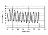
- Preparation of patterned organic EL panel 103 In production of the organic EL panel 101, the irradiation time of the LED in the light emitting part was intermittently irradiated as follows. Other than that, the organic EL panel 103 of the present invention was prepared in the same manner as the organic EL panel 101.
- Irradiance 4 W / cm 2 20 cycles of intermittent irradiation with a period of irradiation time of 15 seconds and a turn-off time of 15 seconds (duty ratio 50%) were performed (total 600 seconds).
- FIG. 6 shows the mask deformation when the light irradiation is performed intermittently in the third embodiment.
- the maximum value of the mask deformation ⁇ Z was 39.8 ⁇ m, which was within the allowable range. Further, it was found that the light emitting function of the organic functional layer was sufficiently lowered and accurate patterning was possible.
- Air blowing part The tip of the spraying part was sprayed in the center direction of the glass mask using a pair of opposed layered air spraying parts having a slit shape.
- the spraying conditions of the pair of layered air spraying portions were the same.
- the patterning method of the organic electroluminescence element of the present invention is highly productive, enables patterning with high dimensional accuracy, and can be preferably applied to a thin organic light-emitting panel.
Landscapes
- Engineering & Computer Science (AREA)
- Manufacturing & Machinery (AREA)
- Physics & Mathematics (AREA)
- General Physics & Mathematics (AREA)
- Condensed Matter Physics & Semiconductors (AREA)
- Computer Hardware Design (AREA)
- Microelectronics & Electronic Packaging (AREA)
- Power Engineering (AREA)
- Electroluminescent Light Sources (AREA)
Abstract
La présente invention aborde le problème de la fourniture d'un procédé de formation de motifs d'élément électroluminescent organique qui a une grande flexibilité et peut effectuer une formation de motifs ayant une précision dimensionnelle élevée. La présente invention aborde également le problème de la fourniture d'un dispositif de formation de motifs d'élément électroluminescent organique. Ce procédé de formation de motifs d'élément électroluminescent organique, dans lequel un motif est formé par exposition d'une couche fonctionnelle organique d'un élément électroluminescent organique à de la lumière par l'intermédiaire d'un masque, est caractérisé en ce que l'exposition à la lumière est effectuée par intermittence dans un état dans lequel l'élément électroluminescent organique est étroitement lié au masque et est placé sur un support de refroidissement.
Priority Applications (1)
| Application Number | Priority Date | Filing Date | Title |
|---|---|---|---|
| JP2018505248A JPWO2017158946A1 (ja) | 2016-03-18 | 2016-12-01 | 有機エレクトロルミネッセンス素子のパターニング方法及びパターニング装置 |
Applications Claiming Priority (2)
| Application Number | Priority Date | Filing Date | Title |
|---|---|---|---|
| JP2016-054616 | 2016-03-18 | ||
| JP2016054616 | 2016-03-18 |
Publications (1)
| Publication Number | Publication Date |
|---|---|
| WO2017158946A1 true WO2017158946A1 (fr) | 2017-09-21 |
Family
ID=59850694
Family Applications (1)
| Application Number | Title | Priority Date | Filing Date |
|---|---|---|---|
| PCT/JP2016/085680 WO2017158946A1 (fr) | 2016-03-18 | 2016-12-01 | Procédé de formation de motifs d'élément électroluminescent organique et dispositif de formation de motifs |
Country Status (2)
| Country | Link |
|---|---|
| JP (1) | JPWO2017158946A1 (fr) |
| WO (1) | WO2017158946A1 (fr) |
Citations (9)
| Publication number | Priority date | Publication date | Assignee | Title |
|---|---|---|---|---|
| JPH04255692A (ja) * | 1991-02-07 | 1992-09-10 | Idemitsu Kosan Co Ltd | 有機エレクトロルミネッセンス素子のパターン化方法 |
| JP2002318555A (ja) * | 2000-12-21 | 2002-10-31 | Semiconductor Energy Lab Co Ltd | 発光装置及びその作製方法 |
| JP2008103409A (ja) * | 2006-10-17 | 2008-05-01 | Fujitsu Hitachi Plasma Display Ltd | 露光装置 |
| WO2012053532A1 (fr) * | 2010-10-20 | 2012-04-26 | 株式会社アルバック | Appareil pour formation de film organique et procédé pour formation de film organique |
| JP2012145869A (ja) * | 2011-01-14 | 2012-08-02 | Hitachi High-Technologies Corp | 露光方法及びその装置 |
| JP2013502063A (ja) * | 2009-08-11 | 2013-01-17 | ズス・マイクロテック・リソグラフィ・ゲゼルシャフト・ミット・ベシュレンクテル・ハフツング | マスクの大きさを一定に維持するための方法および装置 |
| JP2013129866A (ja) * | 2011-12-20 | 2013-07-04 | Ulvac Japan Ltd | 薄膜製造方法、薄膜製造装置 |
| WO2014128848A1 (fr) * | 2013-02-20 | 2014-08-28 | 株式会社日立製作所 | Procédé de formation et dispositif de formation d'un motif à film mince organique |
| WO2015005412A1 (fr) * | 2013-07-11 | 2015-01-15 | コニカミノルタ株式会社 | Procédé et appareil permettant de fabriquer un élément électroluminescent organique et module électroluminescent organique |
-
2016
- 2016-12-01 WO PCT/JP2016/085680 patent/WO2017158946A1/fr active Application Filing
- 2016-12-01 JP JP2018505248A patent/JPWO2017158946A1/ja active Pending
Patent Citations (9)
| Publication number | Priority date | Publication date | Assignee | Title |
|---|---|---|---|---|
| JPH04255692A (ja) * | 1991-02-07 | 1992-09-10 | Idemitsu Kosan Co Ltd | 有機エレクトロルミネッセンス素子のパターン化方法 |
| JP2002318555A (ja) * | 2000-12-21 | 2002-10-31 | Semiconductor Energy Lab Co Ltd | 発光装置及びその作製方法 |
| JP2008103409A (ja) * | 2006-10-17 | 2008-05-01 | Fujitsu Hitachi Plasma Display Ltd | 露光装置 |
| JP2013502063A (ja) * | 2009-08-11 | 2013-01-17 | ズス・マイクロテック・リソグラフィ・ゲゼルシャフト・ミット・ベシュレンクテル・ハフツング | マスクの大きさを一定に維持するための方法および装置 |
| WO2012053532A1 (fr) * | 2010-10-20 | 2012-04-26 | 株式会社アルバック | Appareil pour formation de film organique et procédé pour formation de film organique |
| JP2012145869A (ja) * | 2011-01-14 | 2012-08-02 | Hitachi High-Technologies Corp | 露光方法及びその装置 |
| JP2013129866A (ja) * | 2011-12-20 | 2013-07-04 | Ulvac Japan Ltd | 薄膜製造方法、薄膜製造装置 |
| WO2014128848A1 (fr) * | 2013-02-20 | 2014-08-28 | 株式会社日立製作所 | Procédé de formation et dispositif de formation d'un motif à film mince organique |
| WO2015005412A1 (fr) * | 2013-07-11 | 2015-01-15 | コニカミノルタ株式会社 | Procédé et appareil permettant de fabriquer un élément électroluminescent organique et module électroluminescent organique |
Also Published As
| Publication number | Publication date |
|---|---|
| JPWO2017158946A1 (ja) | 2019-01-17 |
Similar Documents
| Publication | Publication Date | Title |
|---|---|---|
| JP5228268B2 (ja) | 有機エレクトロルミネッセンス素子及び液晶表示装置 | |
| JP5635560B2 (ja) | バルーン型投光機 | |
| JP2008235178A (ja) | 有機elディスプレイの製造方法及び有機elディスプレイ | |
| TW201422056A (zh) | 雷射轉印方法及使用彼之雷射轉印設備 | |
| WO2017158943A1 (fr) | Dispositif de formation de motif et procédé de fabrication d'élément électroluminescent organique | |
| TW486725B (en) | Mercury arc lamp | |
| WO2016151902A1 (fr) | Appareil de formation des motifs et procédé de formation des motifs d'élément électroluminescent organique à l'aide de ce dernier | |
| JP3221121U (ja) | Led面光源ランプ | |
| TW201338656A (zh) | 圖案形成方法及圖案形成基板的製造方法 | |
| JP4946190B2 (ja) | Led紫外線照射装置 | |
| WO2017158946A1 (fr) | Procédé de formation de motifs d'élément électroluminescent organique et dispositif de formation de motifs | |
| JP2008135359A (ja) | 照明装置 | |
| KR100876221B1 (ko) | 발광 다이오드 모듈과 그 제조방법 | |
| US20090203283A1 (en) | Method for sealing an electronic device | |
| WO2017158936A1 (fr) | Procédé de formation des motifs d'élément électroluminescent organique, et dispositif de formation des motifs | |
| JP2001319778A (ja) | 有機el素子 | |
| WO2017158929A1 (fr) | Procédé de formation de motif d'élément électroluminescent organique et dispositif de formation de motif | |
| WO2017158931A1 (fr) | Procédé de formation de motif d'émission de lumière pour un élément électroluminescent organique | |
| WO2017158937A1 (fr) | Procédé de fabrication de corps de formation de motif | |
| JP2010217336A (ja) | 表示装置 | |
| JP2019079596A (ja) | 発光パターン形成用マスク及び有機エレクトロルミネッセンス素子の製造方法 | |
| KR200416139Y1 (ko) | 기판 건조장치 | |
| JP6621629B2 (ja) | 車両用灯具 | |
| WO2017158925A1 (fr) | Mécanisme de maintien de masque et dispositif de formation de motifs le comprenant | |
| GB2261320A (en) | Light emitting panel |
Legal Events
| Date | Code | Title | Description |
|---|---|---|---|
| ENP | Entry into the national phase |
Ref document number: 2018505248 Country of ref document: JP Kind code of ref document: A |
|
| NENP | Non-entry into the national phase |
Ref country code: DE |
|
| 121 | Ep: the epo has been informed by wipo that ep was designated in this application |
Ref document number: 16894563 Country of ref document: EP Kind code of ref document: A1 |
|
| 122 | Ep: pct application non-entry in european phase |
Ref document number: 16894563 Country of ref document: EP Kind code of ref document: A1 |