WO2017158929A1 - Procédé de formation de motif d'élément électroluminescent organique et dispositif de formation de motif - Google Patents
Procédé de formation de motif d'élément électroluminescent organique et dispositif de formation de motif Download PDFInfo
- Publication number
- WO2017158929A1 WO2017158929A1 PCT/JP2016/084390 JP2016084390W WO2017158929A1 WO 2017158929 A1 WO2017158929 A1 WO 2017158929A1 JP 2016084390 W JP2016084390 W JP 2016084390W WO 2017158929 A1 WO2017158929 A1 WO 2017158929A1
- Authority
- WO
- WIPO (PCT)
- Prior art keywords
- light irradiation
- light
- organic
- region
- organic electroluminescence
- Prior art date
Links
- 238000000059 patterning Methods 0.000 title claims abstract description 118
- 238000000034 method Methods 0.000 title claims abstract description 61
- 230000001678 irradiating effect Effects 0.000 claims abstract description 24
- 238000005401 electroluminescence Methods 0.000 claims description 216
- 230000001186 cumulative effect Effects 0.000 abstract 1
- 230000002401 inhibitory effect Effects 0.000 abstract 1
- 239000007789 gas Substances 0.000 description 45
- 239000010410 layer Substances 0.000 description 41
- 239000011521 glass Substances 0.000 description 34
- 239000010408 film Substances 0.000 description 31
- 238000001816 cooling Methods 0.000 description 24
- 230000008569 process Effects 0.000 description 20
- 150000001875 compounds Chemical class 0.000 description 18
- 238000010586 diagram Methods 0.000 description 16
- 239000000463 material Substances 0.000 description 15
- 230000004888 barrier function Effects 0.000 description 13
- 230000007246 mechanism Effects 0.000 description 13
- 238000007789 sealing Methods 0.000 description 13
- 239000000498 cooling water Substances 0.000 description 12
- 239000002346 layers by function Substances 0.000 description 11
- 239000000758 substrate Substances 0.000 description 11
- 230000006866 deterioration Effects 0.000 description 10
- 229920005989 resin Polymers 0.000 description 8
- 239000011347 resin Substances 0.000 description 8
- 229910052782 aluminium Inorganic materials 0.000 description 7
- XAGFODPZIPBFFR-UHFFFAOYSA-N aluminium Chemical compound [Al] XAGFODPZIPBFFR-UHFFFAOYSA-N 0.000 description 7
- 238000004519 manufacturing process Methods 0.000 description 7
- 238000005507 spraying Methods 0.000 description 7
- XLYOFNOQVPJJNP-UHFFFAOYSA-N water Substances O XLYOFNOQVPJJNP-UHFFFAOYSA-N 0.000 description 7
- VYPSYNLAJGMNEJ-UHFFFAOYSA-N Silicium dioxide Chemical compound O=[Si]=O VYPSYNLAJGMNEJ-UHFFFAOYSA-N 0.000 description 5
- 238000000151 deposition Methods 0.000 description 5
- 230000008021 deposition Effects 0.000 description 5
- 230000006870 function Effects 0.000 description 5
- 238000005338 heat storage Methods 0.000 description 5
- 238000010438 heat treatment Methods 0.000 description 5
- 238000002347 injection Methods 0.000 description 5
- 239000007924 injection Substances 0.000 description 5
- VYZAMTAEIAYCRO-UHFFFAOYSA-N Chromium Chemical compound [Cr] VYZAMTAEIAYCRO-UHFFFAOYSA-N 0.000 description 4
- BQCADISMDOOEFD-UHFFFAOYSA-N Silver Chemical compound [Ag] BQCADISMDOOEFD-UHFFFAOYSA-N 0.000 description 4
- 238000007664 blowing Methods 0.000 description 4
- 229910052804 chromium Inorganic materials 0.000 description 4
- 239000011651 chromium Substances 0.000 description 4
- 230000007423 decrease Effects 0.000 description 4
- 238000002360 preparation method Methods 0.000 description 4
- 229910052709 silver Inorganic materials 0.000 description 4
- 239000004332 silver Substances 0.000 description 4
- 239000007921 spray Substances 0.000 description 4
- 238000010521 absorption reaction Methods 0.000 description 3
- 239000000853 adhesive Substances 0.000 description 3
- 230000001070 adhesive effect Effects 0.000 description 3
- 238000009826 distribution Methods 0.000 description 3
- 239000002019 doping agent Substances 0.000 description 3
- 230000000694 effects Effects 0.000 description 3
- 230000005525 hole transport Effects 0.000 description 3
- QSHDDOUJBYECFT-UHFFFAOYSA-N mercury Chemical compound [Hg] QSHDDOUJBYECFT-UHFFFAOYSA-N 0.000 description 3
- 229910052753 mercury Inorganic materials 0.000 description 3
- 239000011368 organic material Substances 0.000 description 3
- 238000001771 vacuum deposition Methods 0.000 description 3
- OKTJSMMVPCPJKN-UHFFFAOYSA-N Carbon Chemical compound [C] OKTJSMMVPCPJKN-UHFFFAOYSA-N 0.000 description 2
- 229920002284 Cellulose triacetate Polymers 0.000 description 2
- NNLVGZFZQQXQNW-ADJNRHBOSA-N [(2r,3r,4s,5r,6s)-4,5-diacetyloxy-3-[(2s,3r,4s,5r,6r)-3,4,5-triacetyloxy-6-(acetyloxymethyl)oxan-2-yl]oxy-6-[(2r,3r,4s,5r,6s)-4,5,6-triacetyloxy-2-(acetyloxymethyl)oxan-3-yl]oxyoxan-2-yl]methyl acetate Chemical compound O([C@@H]1O[C@@H]([C@H]([C@H](OC(C)=O)[C@H]1OC(C)=O)O[C@H]1[C@@H]([C@@H](OC(C)=O)[C@H](OC(C)=O)[C@@H](COC(C)=O)O1)OC(C)=O)COC(=O)C)[C@@H]1[C@@H](COC(C)=O)O[C@@H](OC(C)=O)[C@H](OC(C)=O)[C@H]1OC(C)=O NNLVGZFZQQXQNW-ADJNRHBOSA-N 0.000 description 2
- 239000005354 aluminosilicate glass Substances 0.000 description 2
- 230000015572 biosynthetic process Effects 0.000 description 2
- 229910052799 carbon Inorganic materials 0.000 description 2
- 230000008859 change Effects 0.000 description 2
- 230000000052 comparative effect Effects 0.000 description 2
- 239000011888 foil Substances 0.000 description 2
- 230000020169 heat generation Effects 0.000 description 2
- 238000004020 luminiscence type Methods 0.000 description 2
- 239000012044 organic layer Substances 0.000 description 2
- 230000009467 reduction Effects 0.000 description 2
- 238000004904 shortening Methods 0.000 description 2
- 238000001179 sorption measurement Methods 0.000 description 2
- 239000012780 transparent material Substances 0.000 description 2
- WFKWXMTUELFFGS-UHFFFAOYSA-N tungsten Chemical compound [W] WFKWXMTUELFFGS-UHFFFAOYSA-N 0.000 description 2
- 229910052721 tungsten Inorganic materials 0.000 description 2
- 239000010937 tungsten Substances 0.000 description 2
- 238000007738 vacuum evaporation Methods 0.000 description 2
- RZVAJINKPMORJF-UHFFFAOYSA-N Acetaminophen Chemical compound CC(=O)NC1=CC=C(O)C=C1 RZVAJINKPMORJF-UHFFFAOYSA-N 0.000 description 1
- IJGRMHOSHXDMSA-UHFFFAOYSA-N Atomic nitrogen Chemical compound N#N IJGRMHOSHXDMSA-UHFFFAOYSA-N 0.000 description 1
- CDBYLPFSWZWCQE-UHFFFAOYSA-L Sodium Carbonate Chemical compound [Na+].[Na+].[O-]C([O-])=O CDBYLPFSWZWCQE-UHFFFAOYSA-L 0.000 description 1
- WGLPBDUCMAPZCE-UHFFFAOYSA-N Trioxochromium Chemical compound O=[Cr](=O)=O WGLPBDUCMAPZCE-UHFFFAOYSA-N 0.000 description 1
- 238000009825 accumulation Methods 0.000 description 1
- 230000009471 action Effects 0.000 description 1
- 239000005407 aluminoborosilicate glass Substances 0.000 description 1
- QVGXLLKOCUKJST-UHFFFAOYSA-N atomic oxygen Chemical compound [O] QVGXLLKOCUKJST-UHFFFAOYSA-N 0.000 description 1
- 239000005388 borosilicate glass Substances 0.000 description 1
- 238000006243 chemical reaction Methods 0.000 description 1
- 229910000423 chromium oxide Inorganic materials 0.000 description 1
- 230000003749 cleanliness Effects 0.000 description 1
- 238000000576 coating method Methods 0.000 description 1
- 238000007796 conventional method Methods 0.000 description 1
- 230000009849 deactivation Effects 0.000 description 1
- 230000006837 decompression Effects 0.000 description 1
- 229910001873 dinitrogen Inorganic materials 0.000 description 1
- 230000009977 dual effect Effects 0.000 description 1
- 239000003822 epoxy resin Substances 0.000 description 1
- 238000005530 etching Methods 0.000 description 1
- 238000001704 evaporation Methods 0.000 description 1
- 230000008020 evaporation Effects 0.000 description 1
- 239000010419 fine particle Substances 0.000 description 1
- 108010025899 gelatin film Proteins 0.000 description 1
- 239000002241 glass-ceramic Substances 0.000 description 1
- 238000005286 illumination Methods 0.000 description 1
- 238000009434 installation Methods 0.000 description 1
- 229910052746 lanthanum Inorganic materials 0.000 description 1
- FZLIPJUXYLNCLC-UHFFFAOYSA-N lanthanum atom Chemical compound [La] FZLIPJUXYLNCLC-UHFFFAOYSA-N 0.000 description 1
- 238000012538 light obscuration Methods 0.000 description 1
- 239000004973 liquid crystal related substance Substances 0.000 description 1
- 229910052751 metal Inorganic materials 0.000 description 1
- 239000002184 metal Substances 0.000 description 1
- 229910001507 metal halide Inorganic materials 0.000 description 1
- 150000005309 metal halides Chemical class 0.000 description 1
- 239000007769 metal material Substances 0.000 description 1
- 238000002156 mixing Methods 0.000 description 1
- 239000012299 nitrogen atmosphere Substances 0.000 description 1
- 150000002894 organic compounds Chemical class 0.000 description 1
- 239000001301 oxygen Substances 0.000 description 1
- 229910052760 oxygen Inorganic materials 0.000 description 1
- 239000005365 phosphate glass Substances 0.000 description 1
- 238000000206 photolithography Methods 0.000 description 1
- 229920002120 photoresistant polymer Polymers 0.000 description 1
- 229920000647 polyepoxide Polymers 0.000 description 1
- NROKBHXJSPEDAR-UHFFFAOYSA-M potassium fluoride Chemical compound [F-].[K+] NROKBHXJSPEDAR-UHFFFAOYSA-M 0.000 description 1
- 238000003825 pressing Methods 0.000 description 1
- 239000005297 pyrex Substances 0.000 description 1
- 230000007261 regionalization Effects 0.000 description 1
- 230000004044 response Effects 0.000 description 1
- 238000005096 rolling process Methods 0.000 description 1
- 239000004065 semiconductor Substances 0.000 description 1
- 238000007493 shaping process Methods 0.000 description 1
- 239000005368 silicate glass Substances 0.000 description 1
- 239000005361 soda-lime glass Substances 0.000 description 1
- 239000007787 solid Substances 0.000 description 1
- 239000000243 solution Substances 0.000 description 1
- 229920001187 thermosetting polymer Polymers 0.000 description 1
- 239000010409 thin film Substances 0.000 description 1
- 238000009281 ultraviolet germicidal irradiation Methods 0.000 description 1
- 238000007740 vapor deposition Methods 0.000 description 1
- 229910052724 xenon Inorganic materials 0.000 description 1
- FHNFHKCVQCLJFQ-UHFFFAOYSA-N xenon atom Chemical compound [Xe] FHNFHKCVQCLJFQ-UHFFFAOYSA-N 0.000 description 1
Images


Classifications
-
- H—ELECTRICITY
- H05—ELECTRIC TECHNIQUES NOT OTHERWISE PROVIDED FOR
- H05B—ELECTRIC HEATING; ELECTRIC LIGHT SOURCES NOT OTHERWISE PROVIDED FOR; CIRCUIT ARRANGEMENTS FOR ELECTRIC LIGHT SOURCES, IN GENERAL
- H05B33/00—Electroluminescent light sources
- H05B33/10—Apparatus or processes specially adapted to the manufacture of electroluminescent light sources
-
- H—ELECTRICITY
- H10—SEMICONDUCTOR DEVICES; ELECTRIC SOLID-STATE DEVICES NOT OTHERWISE PROVIDED FOR
- H10K—ORGANIC ELECTRIC SOLID-STATE DEVICES
- H10K50/00—Organic light-emitting devices
- H10K50/10—OLEDs or polymer light-emitting diodes [PLED]
- H10K50/11—OLEDs or polymer light-emitting diodes [PLED] characterised by the electroluminescent [EL] layers
Definitions
- the present invention relates to a patterning method and a patterning device for an organic electroluminescence element. More specifically, the present invention relates to a patterning method and a patterning device for an organic electroluminescence element that are highly productive, prevent deterioration of the light emitting performance of the organic electroluminescence element, and enable accurate patterning.
- organic light emitting panels are attracting attention as thin light emitting devices.
- an organic electric luminescence element (hereinafter also referred to as an “organic EL element”) using electroluminescence (EL) of an organic material is a thin film that can emit light at a low voltage of about several V to several tens V.
- This is a complete solid panel of a mold, can obtain high brightness with low power, has excellent features such as visibility, response speed, life and power consumption, and can be made thin and lightweight.
- various displays using organic EL elements as panels, backlights thereof, display boards such as signboards and emergency lights, and surface light emitters such as illumination light sources have attracted attention in recent years.
- Such an organic EL panel has a configuration in which a light emitting layer made of an organic material is disposed between two electrodes, and emitted light generated in the light emitting layer passes through the electrode and is extracted outside. For this reason, at least one of the two electrodes is configured as a transparent electrode, and emitted light is extracted from the transparent electrode side.
- the organic functional layer of the organic EL element laminated on the substrate is irradiated with ultraviolet rays to deactivate the irradiated portion.
- a method for manufacturing an organic EL element that forms a light-emitting pattern having a non-light-emitting region has been disclosed (for example, see Patent Document 1).
- the organic EL element which has a light emission pattern can also be manufactured by changing the irradiation light quantity to an organic EL element through an image-like mask.
- Patent Document 1 when patterning is performed by irradiating each individual organic EL element, patterning of a plurality of organic EL elements requires a lot of man-hours and is inferior in productivity. In addition, there is a problem that even if a large number of irradiation devices for light irradiation are prepared and a plurality of elements are patterned at the same time, it takes time to arrange a large number of elements.
- a film-like or panel-like member (hereinafter referred to as “organic electroluminescence sheet”) in which a plurality of organic EL elements are provided on the plane of the substrate is irradiated with ultraviolet rays all over the entire surface, so that many Patterning can be performed on the organic EL element.
- the organic EL element itself is more vulnerable to heat because the structure of the organic EL element is more complex than that of a photoresist used in the manufacture of circuits such as semiconductors and liquid crystal display devices.
- the film quality of the organic material changes due to heat, resulting in a change in luminous efficiency, chromaticity, and a decrease in lifetime.
- white light is emitted by mixing blue light, green light, and red light
- color tolerance is difficult to maintain because the color balance is difficult to maintain, and color balance is easily lost due to heat.
- Patent Document 3 discloses a technique for irradiating light by emitting light while changing the light irradiation conditions of a plurality of pulsed light when irradiating the applied photosensitive material. Further, it is described that the pattern forming body mounting table may be moved stepwise to sequentially irradiate the entire surface with light. However, even if the light irradiation condition is changed as in Patent Document 3, it is insufficient for an organic EL element that is easily affected by heat as described above. In addition, when a plurality of pulsed light irradiations are performed, the turn-off time of intermittent irradiation is wasted and the tact time is increased, resulting in poor productivity. In particular, in an organic EL device having poor heat stability, it is necessary to make the intermittent irradiation extinguishing time longer, and the productivity is greatly inferior.
- the present invention has been made in view of the above-mentioned problems and situations, and its solution is high in productivity, while preventing deterioration of the light emitting performance of the organic electroluminescence element and suppressing the thermal deformation of the mask and accurately. It is to provide a patterning method for an organic EL element that can be patterned. Moreover, it is providing the patterning apparatus of the organic EL element for it.
- the present inventors divided light irradiation regions of an organic electroluminescence sheet provided with a plurality of organic EL elements into a plurality of light irradiation regions and sequentially performed light irradiation. By repeating the light irradiation to the same region again, it was found that the productivity was high, the light emitting performance of the organic electroluminescence element was prevented from being deteriorated, and the mask was accurately deformed by suppressing thermal deformation. It was.
- An organic electroluminescence element patterning method for forming an emission pattern of an organic electroluminescence element by irradiating an organic electroluminescence sheet provided with a plurality of organic electroluminescence elements with light through a mask, the mask comprising: A first light irradiation step in which light irradiation is performed in one light irradiation region (A) of the plurality of light irradiation regions; and After the one light irradiation step, after the second light irradiation step, a second light irradiation step of performing light irradiation in one light irradiation region (B) of the light irradiation regions other than the light irradiation region (A) An additional light irradiation step of performing light irradiation again on the light irradiation region (A) of the first light irradiation step, and the integrated irradiation light amount in the plurality of light irradiation regions is So that a predetermined amount of light
- At least one light source unit performs light irradiation on one light irradiation region (A) among the plurality of light irradiation regions, thereby performing the first light irradiation step, and after the first light irradiation step.
- the step moves between the plurality of light irradiation regions by changing the relative position between the light source unit and the organic electroluminescence sheet, and after the step movement, the light irradiation is performed in the first light irradiation step.
- the plurality of light irradiation regions are associated with one of a plurality of light source units for performing light irradiation, and the light source corresponding to one light irradiation region (A) among the plurality of light irradiation regions.
- the light irradiation region (A) is irradiated with light by the unit to perform the first light irradiation step, and after the first light irradiation step, the positions of the plurality of light source units and the relative position of the organic electroluminescence sheet By irradiating the light irradiation region (B) with the light source unit corresponding to the light irradiation region (B) other than the light irradiation region subjected to the light irradiation in the first light irradiation step without changing the position. 2.
- a pattern-forming object mounting table that holds an organic electroluminescence sheet provided with a plurality of organic electroluminescence elements, at least one light source unit that irradiates light to a plurality of light irradiation regions of the organic electroluminescence sheet, and A step moving unit that changes a relative position between the position of the light source unit and the pattern-formed object mounting table, and a light source unit so that an integrated light amount in each of the plurality of light irradiation regions is a predetermined amount in each light irradiation region
- the step moving unit performs light irradiation in at least one light irradiation region (A) among the plurality of light irradiation regions, and then performs light other than the light irradiation region (A).
- a light source part or a pattern forming body mounting table is moved to a position where light irradiation is performed in at least one light irradiation area (B) of the irradiation areas, and the light irradiation area
- An organic electroluminescence device which is a step moving unit that moves the light source unit or the pattern-formed-body mounting table to a position where light irradiation is performed again in the light irradiation region (A) after performing light irradiation in B) Patterning equipment.
- a pattern-forming object mounting table that holds an organic electroluminescence sheet provided with a plurality of organic electroluminescence elements, a plurality of light source units that irradiate light to a plurality of light irradiation regions of the organic electroluminescence sheet, and the plurality
- a patterning device for an organic electroluminescence sheet comprising a control unit for controlling a light source unit, wherein the positions of the plurality of light source units are fixed, and the plurality of light irradiation regions are any of the plurality of light source units.
- the control unit controls a plurality of light source units and performs light irradiation in the light irradiation region (A) by the light source unit corresponding to at least one light irradiation region (A).
- the light source unit corresponding to at least one light irradiation region (B) of the light irradiation regions other than the light irradiation region (A) is used for the light.
- the light irradiation is performed in the irradiation region (B), the light irradiation is performed in the light irradiation region (B), and then the light irradiation region (A) is irradiated again.
- a patterning device for an organic electroluminescence element wherein the light source unit is controlled so as to be a predetermined amount in each light irradiation region.
- the present invention it is possible to provide a patterning method for an organic electroluminescence device that is highly productive, prevents deterioration of the light emitting performance of the organic electroluminescence device, and can perform accurate patterning by suppressing thermal deformation of the mask. it can. Moreover, the patterning apparatus of the organic electroluminescent element for that can be provided.
- the expression mechanism or action mechanism of the effect of the present invention is as follows.
- a light emitting pattern having a non-light emitting region by irradiating the organic functional layer of the organic EL element with ultraviolet light and deactivating the ultraviolet light irradiated portion
- the mask is deformed by heat storage.
- intermittent irradiation is performed by pulsed light irradiation to prevent heat storage
- the tact time becomes longer by the extinguishing time at the time of intermittent operation, resulting in poor productivity.
- the turn-off time is shortened for shortening the tact time, heat storage is not sufficiently prevented, which is particularly problematic in the case of an organic EL element that is easily affected by heat and easily changes in color balance.
- a light irradiation area of an organic electroluminescence sheet (hereinafter also referred to as “organic EL sheet”) having a plurality of organic EL elements in a planar shape is divided into a plurality of light irradiation areas to reduce the light irradiation area.
- organic EL sheet organic electroluminescence sheet
- the amount of heat generated by the mask is suppressed and light irradiation is sequentially performed, and then light irradiation is repeated on the same region again. Since the first light irradiation area is allowed to cool while the light irradiation is sequentially performed on a plurality of light irradiation areas, the turn-off time is not required when intermittent irradiation is performed by the pulse light irradiation. Time is shortened. Further, heat storage is sufficiently prevented, and accurate patterning can be performed even on an organic EL element that is easily affected by heat and easily changes in color balance.
- FIG. 1 Schematic diagram of organic EL sheet Schematic diagram of mask Schematic diagram of an example of light irradiation area
- FIG. 1 The perspective view of an example of the light irradiation part of the patterning apparatus of this invention
- FIG. 1 is an overall configuration diagram of an example of a patterning apparatus of the present invention (a diagram viewed from the X-axis direction).
- 1 is an overall configuration diagram of an example of a patterning apparatus of the present invention (a diagram viewed from the Y-axis direction).
- Operation flow diagram of an example of patterning method of the present invention Cross-sectional view of an example of an organic EL element Schematic diagram of another example of light irradiation area
- the organic electroluminescent element patterning method of the present invention is a method for forming an organic electroluminescent element light-emitting pattern by irradiating an organic electroluminescent sheet provided with a plurality of organic electroluminescent elements through a mask.
- a region irradiated with light through the mask is divided into a plurality of light irradiation regions, and light is emitted from one light irradiation region (A) among the plurality of light irradiation regions.
- the additional light that irradiates the light irradiation region (A) in the first light irradiation step again.
- Morphism includes the step, accumulated light quantity of the plurality of light irradiation region, so that a predetermined amount of each of the light irradiation region, and a light irradiation process is repeated. This feature is a technical feature common to the claimed invention.
- the second light irradiation step is performed by irradiating the light irradiation region (B) other than the light irradiation region subjected to the light irradiation in the first light irradiation step with the light source unit.
- productivity is high and it is possible to prevent deterioration of the light emitting performance of the organic electroluminescence element and to perform more accurate patterning while suppressing thermal deformation of the mask.
- region is matched with either of the several light source parts for light irradiation, The position of the said several light source part, and the said organic electroluminescent sheet
- a patterning device for an organic electroluminescence element used in the present invention As a patterning device for an organic electroluminescence element used in the present invention, a pattern forming body mounting table for holding an organic electroluminescence sheet provided with a plurality of organic electroluminescence elements, and a plurality of light irradiations of the organic electroluminescence sheet At least one light source unit that irradiates the region with light, a step moving unit that changes a relative position between the position of the light source unit and the pattern forming object mounting table, and an integrated light amount in the plurality of light irradiation regions.
- a control unit that controls the light source unit so that a predetermined amount is obtained in each light irradiation region, and the step moving unit performs light irradiation in at least one light irradiation region (A) among the plurality of light irradiation regions. After performing, at least one light irradiation region (B) of the light irradiation regions other than the light irradiation region (A). After moving the light source unit or the pattern forming body mounting table to the position where light irradiation is performed in step, and performing light irradiation in the light irradiation region (B), the light source is moved to the position where light irradiation is performed again on the light irradiation region (A).
- the patterning device for an organic electroluminescence element is a step moving unit for moving the unit or the pattern forming body mounting table.
- productivity is high, deterioration of the light emitting performance of the organic electroluminescence element can be prevented, and more accurate patterning can be performed.
- a patterning device for the organic electroluminescence element used in the present invention a pattern forming body mounting table that holds an organic electroluminescence sheet provided with a plurality of organic electroluminescence elements, and a plurality of organic electroluminescence sheets
- a patterning device for an organic electroluminescence sheet comprising a plurality of light source units for irradiating light to a light irradiation region and a control unit for controlling the plurality of light source units, wherein the positions of the plurality of light source units are fixed
- the plurality of light irradiation regions are associated with one of the plurality of light source units, and the control unit controls the plurality of light source units to correspond to at least one light irradiation region (A).
- the light irradiation region (A) After performing light irradiation in the light irradiation region (A) by the light irradiation unit, the light irradiation region (A) Light irradiation was performed in the light irradiation region (B) by the light source unit corresponding to at least one light irradiation region (B) in the outside light irradiation region, and light irradiation was performed in the light irradiation region (B). Later, the light irradiation area (A) is again irradiated with light, and the patterning of the organic electroluminescence element that controls the light source unit so that the accumulated light quantity in the plurality of light irradiation areas becomes a predetermined amount in each light irradiation area. An apparatus is preferred. Thereby, productivity is high, and while the deterioration of the light emission performance of an organic electroluminescent element can be prevented, more accurate patterning can be performed.
- ⁇ is used to mean that the numerical values described before and after it are included as a lower limit value and an upper limit value.
- the patterning method of the present invention is a method for patterning an organic electroluminescent element in which a light emitting pattern of an organic electroluminescent element is formed by irradiating an organic electroluminescent sheet provided with a plurality of organic electroluminescent elements through a mask.
- the region irradiated with light through the mask is divided into a plurality of light irradiation regions, and light irradiation is performed in one light irradiation region (A) among the plurality of light irradiation regions.
- the light irradiation region (A) of the first light irradiation step includes an additional light irradiation step of performing light irradiation again, and the plurality of light irradiation regions Definitive total irradiation quantity of light, to a predetermined amount in each of the light irradiation region, and a light irradiation process is repeated.
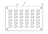
- FIG. 1A and 1B are schematic views of an organic EL sheet and a mask.
- FIG. 1A is a schematic diagram of an organic EL sheet.
- a plurality of organic EL elements 12 are formed on the organic EL sheet 11, and organic EL alignment marks 13 are formed at the four corners. This alignment mark is used for alignment of a film formation mask when forming an electrode or an organic layer in the manufacture of an organic EL element.
- FIG. 1B is a schematic diagram of a mask.
- a predetermined light irradiation pattern 15 (character A in the example in the figure) is formed on the mask 14 at a position corresponding to each organic EL element, and a mask alignment mark 16 corresponding to the position of the alignment mark 13 on the organic EL sheet 11. Is formed.
- the blackened portion shields the ultraviolet rays by the light shielding film. Therefore, the organic EL element is irradiated with ultraviolet light in a light emitting area other than the letter A and does not emit light, and only the letter A emits light as the organic EL element.
- the mask substrate is preferably quartz glass or heat-resistant glass (Pyrex (registered trademark) or Tempax) having a small linear expansion coefficient
- the light-shielding film is preferably a chromium film or a chromium oxide film having a low ultraviolet absorption rate.
- the organic EL sheet 11 is cut for each organic EL element 12.
- Each individual organic EL element thus cut is used to be individually loaded into a display device or the like.
- FIG. 2 is a schematic diagram showing a light irradiation region.
- the dotted line portion in the figure is a plurality of light irradiation regions, and in the case of FIG. 2, the case where it is divided into four light irradiation regions (P1 to P4) is illustrated.
- the tact time in the case where the four light irradiation areas are irradiated 10 times with one pulse light irradiation is illustrated.
- 1 pulse light irradiation irradiance 4 ⁇ 10 4 W / m 2
- is irradiated for 30 seconds light amount 1.2 ⁇ 10 6 J / m 2
- One pulse light irradiation is applied for 30 seconds.
- each of the light irradiation regions P3 and P4 is also irradiated with one pulse of light for 30 seconds.
- one-pulse irradiation is sequentially repeated.
- the light irradiation is repeated 10 times until the integrated light quantity at each position becomes 1.2 ⁇ 10 7 J / m 2 (circumferential light irradiation method).
- There is a waiting time of 94 seconds before returning to the light irradiation region P1 and since the light irradiation region P1 is sufficiently cooled during this time, heat accumulation in the mask and the organic EL sheet does not occur during light irradiation. .
- the tact time required to complete the light irradiation is (light irradiation 30 seconds + step movement 1 second) ⁇ 4 steps ⁇ 10 times, which is 1240 seconds.
- the tact time in the case where the four light irradiation regions are completed by one round of multipulse light irradiation (intermittent light irradiation) (when the present invention is not used) is exemplified.
- one pulse light irradiation (irradiance 4 ⁇ 10 4 W / m 2 ) is irradiated for 30 seconds (light amount 1.2 ⁇ 10 6 J / m 2 ) and then turned off for 30 seconds.
- This intermittent light irradiation is repeated 10 times, and light irradiation is performed until the integrated light amount becomes 1.2 ⁇ 10 7 J / m 2 .
- the light irradiation region P2 is moved in 1 second and the same light irradiation is performed.
- the same light irradiation is performed for the light irradiation region P3 and the light irradiation region P4.
- the tact time is (irradiation 30 hours seconds + light-off time 30 seconds) ⁇ 10 times ⁇ 4 positions + step movement 1 second ⁇ 3 steps, 2403 seconds.
- the tact time can be reduced to almost half of the comparative intermittent light irradiation.
- the light irradiation area in the present invention is divided into a plurality of parts.
- the number of light irradiation regions to be divided is not particularly limited, but is preferably 9 or less, and more preferably 4 or less from the viewpoint of shortening the tact time. More preferably, it is divided into two.
- a repetition order of the light irradiation region for example, a case where (light irradiation region P1 ⁇ light irradiation region P2 ⁇ light irradiation region P1 ⁇ light irradiation region P2) is repeated may be mentioned, but re-lighting is performed in at least one light irradiation region. As long as irradiation is performed, any light irradiation order may be sufficient.
- the light irradiation order may be different from the light irradiation order of the first round.
- the shape of the light irradiation region to be divided may be any of square, rectangle and the like.
- the irradiance and the light irradiation time of one pulse may be changed at each position.
- one pattern may be formed with a plurality of organic EL elements (for example, 100 organic EL elements in a total of 10 rows and 10 rows).
- the plurality of organic EL elements form different patterns, and operate as an organic EL panel that displays one pattern as a whole.
- a pattern forming body mounting table for holding an organic electroluminescence sheet provided with a plurality of organic electroluminescence elements, and a plurality of light irradiation regions of the organic electroluminescence sheet
- At least one light source unit that performs light irradiation
- a step moving unit that changes a relative position between the position of the light source unit and the pattern forming body mounting table, and an integrated light amount in each of the plurality of light irradiation regions
- a control unit that controls the light source unit so that a predetermined amount is obtained in the light irradiation region, and the step moving unit performs light irradiation in at least one light irradiation region (A) among the plurality of light irradiation regions.
- At least one light irradiation region (B) other than the light irradiation region (A) is irradiated with light.
- the light source part or the pattern forming body mounting table is moved to the light irradiation area (B), and then the light irradiation area (A) is irradiated with light again.
- a patterning device for an organic electroluminescence element which is a step moving unit for moving the mounting table is preferable.
- FIG. 3 is a perspective view of an example (first embodiment) of the light irradiation unit of the patterning apparatus of the present invention. *
- a light source section 35 for example, a UV-LED having a wavelength of 365 nm or 385 nm
- the heat of the LED generated at the time of irradiation escapes to the heat radiating plate 33 and prevents the light emission efficiency of the LED from being lowered. It is more preferable to provide a cooling pipe inside the heat radiating plate 33 and circulate cooling water to cool the LED with water.
- the divergent light emitted from the light source unit 35 is used as irradiation light 38 shaped into a light beam having a predetermined divergence angle by the lens array 37.
- Irradiation light 38 is confined by a cover 39 whose inner surface is a reflective surface to prevent a decrease in the amount of light, and the organic EL sheet 11 is irradiated with light through the mask 14 with a uniform amount of light.
- the gap WD between the lower end of the cover and the mask should be as narrow as possible, preferably about 5 mm. If it is this space
- the light emitted from the light source unit 35 is preferably ultraviolet light whose deactivation reaction rate of the organic functional layer is fast from the viewpoint of reducing the tact time.
- the light irradiation performed in one light irradiation step is preferably pulsed light irradiation. Furthermore, it is more preferable that it is 1 pulse light irradiation.
- the intermittent time (total of light extinction time) between one light irradiation steps, It is preferably 25% or less, more preferably 10% or less, of the time required for the single light irradiation step. Most preferably, the intermittent time is 0%.
- the light source unit 35 (LED) is irradiated with light by being controlled by the light source control unit 56 to be turned on / off or irradiated and turned on.
- the lens array 37 is used for divergence angle shaping, a condensing mirror such as a compound parabolic concentrator may be used.
- the organic EL sheet 11 is placed on the pattern forming body placing table 43, and the mask 14 is adjusted to a predetermined relative position with the organic EL sheet 11 and placed on the sheet.
- the organic EL sheet 11 is preferably fixed by adsorption.
- PET or PEN is used for the substrate, the organic EL sheet is easily deformed, such as curling, but by adsorbing the entire surface of the sheet, it can be fixed to the pattern forming object mounting table with good flatness and prevent light irradiation blur of patterning it can.
- the pattern forming body mounting table 43 cools the organic EL sheet by a water cooling method. Cooling pipes 44a and 44b are provided inside the pattern forming body mounting table to cool the heat generated in the mask and the organic EL sheet by ultraviolet irradiation.
- the water that has absorbed the heat in the pattern forming body mounting table is sent to a chiller unit 58 installed outside (not shown), heat is exchanged inside the chiller unit, and the cooling water whose temperature is lowered is supplied to the pattern forming body mounting table. Supplied.
- the cooling water circulates through the chiller unit and the pattern forming body mounting table. The cooling function is always operated while the device is in operation.
- the water temperature introduced into the pattern forming body mounting table is preferably 30 ° C. or less as long as the organic EL sheet and the mask do not condense. 10 to 20 ° C. is more preferable.
- the material of the pattern forming body mounting table is preferably a metal having high thermal conductivity. For example, aluminum can be used.
- Gas is blown out from the gas flow generation unit 40 in a line shape, and the gas flow 41 cools the mask surface.
- the gas blown by the gas flow generating part is not particularly limited as long as it can cool the mask and does not impair the effects of the present invention.
- air or nitrogen gas can be suitably used.
- the glass mask 14 irradiated with ultraviolet rays becomes high temperature and thermally expands, and patterning with high dimensional accuracy is likely to be difficult. Moreover, the organic EL sheet 11 is heated, and the light emission performance of the organic EL element is likely to be deteriorated.
- the light irradiation area of the organic EL sheet is divided into a plurality of light irradiation areas to reduce the light irradiation area, thereby suppressing the heat generation amount of the mask and sequentially performing the light irradiation, and then the same again.
- the productivity is high, the deterioration of the light emitting performance of the organic electroluminescence element is prevented, and accurate patterning can be performed.
- the light irradiation unit 32 irradiates the first light irradiation region P ⁇ b> 1 of the organic EL sheet 11
- the light irradiation unit 32 and the pattern forming body mounting table 43 move stepwise.
- the next light irradiation region P2 is irradiated with light.
- the light irradiation region P1 is again irradiated with light.
- the glass mask 14 is prevented from being deformed by heat and the color balance of the organic EL sheet 11 is prevented from being accurately patterned. Further, the time tact for patterning can be shortened, and productivity can be improved.
- a patterning apparatus used in the patterning method of the present invention, a pattern forming body mounting table for holding an organic electroluminescence sheet provided with a plurality of organic electroluminescence elements, and a plurality of light irradiation regions of the organic electroluminescence sheet
- a patterning device for an organic electroluminescence sheet comprising a plurality of light source units for irradiating light and a control unit for controlling the plurality of light source units, wherein the positions of the plurality of light source units are fixed,
- the light irradiation region is associated with one of the plurality of light source units, and the control unit controls the plurality of light source units by the light irradiation unit corresponding to at least one light irradiation region (A).
- the light source corresponding to at least one light irradiation region (B) is irradiated with light in the light irradiation region (B), and after the light irradiation is performed in the light irradiation region (B), the light irradiation region (A
- the light source unit is controlled so that the integrated light quantity in the plurality of light irradiation regions becomes a predetermined amount in each light irradiation region. Preferably there is.
- FIG. 4 is a perspective view of another example (second embodiment) of the light irradiation unit of the patterning apparatus of the present invention.
- a plurality of light source sections 35 are arranged, and the light irradiation area of the light emitted from the entire light irradiation section 32 is an area that can cover the entire area where the organic EL element of the sheet is disposed. . That is, when all the light source parts 35 are turned on, the light irradiation area covers all the light irradiation areas P1, P2, P3 and P4 in FIG.
- the light source unit 35 can be controlled for each group, and in the first light irradiation step, only the LED light source unit of the first group is turned on, and the irradiation light 1 (38a) that irradiates the light irradiation region P1 in FIG. ) Is emitted.
- irradiation light 2 (38b) for irradiating the light irradiation region P2 in FIG. 2 is emitted.
- irradiation light 2 (38b) for irradiating the light irradiation region P2 in FIG. 2 is emitted.
- the light source unit 35 in one light irradiation unit 32 is sequentially turned on.
- a plurality of (for example, four) light irradiation units 32 in the first embodiment of the patterning device described above are arranged, and each light Each light irradiation unit 32 may be caused to emit light sequentially in accordance with the light irradiation of the irradiation regions (P1 to P4).
- the gas flow generating unit 40 is arranged at a position facing the upper surface of the glass mask 14 such that gas is blown in parallel to the glass mask 3 and toward the center of the glass mask 14 through the gap WD between the glass mask 14 and the cover 39. Has been.
- the gas flow generating unit 40 is disposed on the upper surface of the glass mask 14 and sprayed in parallel with the glass mask 14, whereby the gas flow 41 to be sprayed travels on the glass mask 14 evenly and joins at the center of the glass mask.
- To spray in parallel means to spray at an angle within ⁇ 2 degrees with respect to the plane of the glass mask 3.
- the gas flow generation unit 40 is disposed in parallel to the opposing position on the upper surface of the glass mask 14.
- the distance 42 between the cover 39 and the gas flow generating unit 40 is not particularly limited as long as air is efficiently blown onto the mask, but is preferably within a range of 10 to 200 mm. More preferably, it is within the range of 30 to 100 mm.
- the length of the gas flow generating part is preferably the same as or larger than the width of the cover on the side to be sprayed.
- the pair of gas flow generation units 40 is disposed at a symmetrical position with respect to the central portion of the glass mask 14.
- cooling pattern pipes 44a and 44b are provided inside the pattern forming body mounting table 43, and a chiller unit 58 that cools the organic EL sheet and the mask by circulating cooling water through the cooling pipe is preferably provided.
- the gas flow generation unit 40 is preferably provided with a slit-shaped or nozzle-shaped sprayed portion. It is more preferable to have a slit-shaped spraying part.
- the number of nozzles is preferably large, and the number of nozzles is preferably one at intervals of 5 to 20 mm.
- the size of the nozzle diameter can be adjusted as appropriate.
- a commercially available product can be used as the slit-shaped spraying part used for the spraying part.
- a layered airflow generator 750 type manufactured by Sanwa Enterprise, a blower knife air nozzle manufactured by Spraying System Japan, or the like can be used.
- the air volume blown from the pair of blowing parts is the same.
- the air volume can be 1000 to 4000 L / min.
- the gas flow generator is preferably connected to an air compressor. According to the irradiation light quantity of an ultraviolet-ray, it can adjust to a desired air volume and a wind speed suitably.
- a known air compressor can be used.
- the air to be blown is temperature-adjusted. If necessary, the cooling efficiency can be increased by using air whose temperature is adjusted to about 5 to 15 ° C., for example.
- the cover has a reflection light guiding function that prevents a reduction in the amount of ultraviolet light emitted from the lens array and irradiates the glass mask with a uniform amount of light. Therefore, it is preferable that the inner surface is covered with a reflective material. Since the reflective material is resistant to heat and durable, a metal material can be used. For example, aluminum is preferably used because it is lightweight.
- the height and bottom area are not particularly limited, and the organic EL sheet irradiates ultraviolet rays. It can be set according to the size of.
- the bottom surface is preferably larger than the area where the organic EL elements are arranged.
- the height of the cover can be adjusted as appropriate based on the amount of ultraviolet light and unevenness in the amount of irradiation light. For example, it can be about 0.5 to 5 m.
- a light source that emits ultraviolet rays is attached to the light source unit.
- the light source is not particularly limited as long as it is a light source that emits a desired amount of ultraviolet light.
- Ultraviolet light having a wavelength range of 400 nm can be used. It is desirable to use a UV-LED that can easily control pulse irradiation electrically and can increase the output of the light source.
- One or a plurality of light sources may be used for the light source unit, but it is preferable to arrange a plurality of light sources in a two-dimensional manner to form one light source unit.
- the integrated light irradiation amount for performing the patterning method of the present invention is 2 ⁇ 10 6 to 5 ⁇ 10 7 J / m 2 , although it depends on the layer structure, film thickness, panel size, etc. of the organic EL element. Irradiation with a light amount is preferable from the viewpoint of high productivity and accurate patterning with good contrast between the light emitting portion and the non-light emitting portion. Further, it is preferable that one pulse of ultraviolet irradiation time is in the range of 1 to 300 seconds.
- a mask has a role which changes the light quantity irradiated to an organic EL element.
- a glass mask having a negative pattern on a glass substrate can be manufactured using a known mask material that can change the amount of transmitted ultraviolet light. By irradiating the organic EL element with ultraviolet rays through this mask, an organic EL element having a light emission pattern can be produced.
- a photographic image can be produced by using a black and white photographic negative image in which silver fine particles are dispersed in a gelatin film.
- the “pattern” here means a design (design or pattern of a figure), characters, images, etc. displayed by the organic EL element. “Patterning” refers to providing these pattern display functions.
- the “light emission pattern” refers to light emitted from an organic EL element that emits light with varying light emission intensity (luminance) depending on the position of the light emitting surface, based on a predetermined design (pattern or pattern in the figure), characters, images, etc.
- the glass substrate is not particularly limited as a material, and for example, a known glass material used for optics or a substrate can be used.
- glass ceramics such as aluminosilicate glass, soda lime glass, soda aluminosilicate glass, aluminoborosilicate glass, borosilicate glass, quartz glass, chain silicate glass, crystallized glass, heat-resistant glass, phosphate glass or Examples thereof include lanthanum-based glass.
- Quartz glass and heat-resistant glass can be preferably used.
- the thickness of the glass mask is not particularly limited, but a glass mask having a thickness of 3 to 10 mm can be used.
- ⁇ Chiller> In addition to cooling with the gas blown from the gas flow generation unit, it is preferable to cool the organic EL sheet and the mask by providing the pattern forming body mounting table with a cooling function. Since the organic EL sheet is as thin as 0.1 to 0.5 mm, the heat generated in the light shielding film of the mask due to ultraviolet irradiation is also cooled through the organic EL sheet. As a cooling method, a known method can be mentioned, but a water cooling method is preferable because it is simple and effective. A cooling pipe is provided inside the pattern forming body mounting table, and cooling water flows through the cooling pipe and absorbs heat generated in the mask and the organic EL sheet by ultraviolet irradiation.
- the cooling water that has absorbed heat by the pattern forming body mounting table is sent to the chiller unit installed outside, heat is exchanged inside the chiller unit, and the cooling water whose temperature is lowered is supplied to the pattern forming body mounting table.
- the cooling water circulates through the chiller unit and the pattern forming body mounting table.
- the “chiller” refers to a device that circulates a heat medium and keeps the target part at a constant temperature.
- the chiller unit has a built-in cooler for heat exchange and a pump for circulating cooling water.
- FIG. 3 and FIG. 4 show an example in which the cooling pipes 44a and 44b provided on the pattern forming body mounting table 43 flow circulating water. Cooling water is introduced through the cooling pipe (introduction) 44a and discharged from the cooling pipe (discharge) 44b, and the discharged water is cooled again and circulated to cool the organic EL sheet 11 and the mask 14 irradiated with ultraviolet rays. be able to.
- the material of the pattern forming body mounting table preferably has a high thermal conductivity.
- aluminum can be used.
- ⁇ Circular light irradiation mechanism> In the present invention, after the light irradiation area of the organic EL sheet is divided into a plurality of light irradiation areas and sequentially irradiated with light, the same area is repeatedly irradiated with light again, and a predetermined integrated light irradiation amount is obtained in each light irradiation area. Repeat the light irradiation until Therefore, it is necessary to control the light irradiation area so as to go around.
- FIG. 5 is an overall configuration diagram (a diagram viewed from the X-axis direction) of an example of the patterning device of the present invention (a first mode of the patterning device).
- FIG. 6 is an overall configuration diagram (a diagram viewed from the Y-axis direction) of an example of the patterning device of the present invention (a first embodiment of the patterning device).
- the pattern forming body mounting table 43 moves along the linear guide 64 in the X-axis direction.
- the screw shaft 66 is rotated by the motor 67, and the rotational movement is converted into the straight movement by the ball screw 65 attached to the bottom surface of the pattern forming object mounting table 43, and moved.
- the reference position is determined by a position sensor (not shown), and the movement amount is controlled by the number of rotations of the motor 67 from there.
- the light irradiation unit 32 is similarly moved in the Y-axis direction by the linear guide 68.
- the linear guide 68 of the light irradiation unit is installed on a base on which a support is placed.
- the operation unit 52 has a built-in memory, and stores light irradiation conditions such as irradiance per light irradiation at each position, light irradiation time, number of times of light irradiation, coordinates of each light irradiation position, and movement order. ing.
- the desired light irradiation conditions are selected by the operation unit 52, and the control unit 53 controls the following mechanisms according to the conditions.
- the control unit 53 includes a mask alignment control unit 54, a movement mechanism control unit 55, a light source control unit 56, and an air flow control unit 57.
- the light source control unit 56 controls the irradiance, light irradiation time, the number of times of light irradiation, etc. of the light source unit 35.
- the movement mechanism control unit 55 controls the positions of the pattern forming body mounting table 43 and the light irradiation unit 32 via the motor 67 and the motor 61.
- the mask alignment control unit 54 controls the mask alignment device 69 in a state where the pattern forming object mounting table 43 is at the mask alignment position, and places the mask 14 at a predetermined position on the organic EL sheet 11.
- the air flow control unit 57 controls on / off of the operation of the air flow generation unit 40.
- FIG. 7 is a flowchart showing an operation flow of an example of the patterning method of the present invention (when the first embodiment of the patterning apparatus is used and there are four light irradiation regions).
- step S101 light irradiation conditions are selected. Light irradiation conditions are selected using a touch panel (not shown) of the operation unit 52. Further, the ID number of the organic EL sheet 13 is input. Next, the process proceeds to step S102.
- step S ⁇ b> 102 the organic EL sheet 11 is set on the pattern forming body mounting table 43.
- the pattern forming body mounting table 43 is in a position retracted from the light source unit, and the organic EL sheet 11 is installed and collected at this position.
- a suction start button is pressed on a touch panel (not shown) of the operation unit 52, and the organic EL sheet 11 is sucked and fixed in a suction hole (not shown) provided on the pattern forming body mounting table 43.
- the process proceeds to step S103.
- step S103 mask alignment is performed, and the mask 14 is placed at a predetermined position of the organic EL sheet 11.
- a light irradiation start button is pressed on a touch panel (not shown) of the operation unit 52, the pattern forming body mounting table 43 on which the organic EL sheet 11 is mounted moves to the mask alignment position.
- Mask alignment is performed by the mask alignment apparatus 69, and the mask 14 is placed in close contact with the organic EL sheet 11.
- the process proceeds to step S104.
- step S104 circular step light irradiation is performed.
- the pattern forming body mounting table 43 When the circular step light irradiation is started, the pattern forming body mounting table 43 first moves to the light irradiation position.
- the moving mechanism control unit 55 moves the pattern forming body mounting table 43 through the ball screw 65 so as to be a predetermined place in the light irradiation region P1.
- the gas flow control unit 57 operates the gas flow generation unit 40 to start air cooling.
- the moving mechanism control unit 55 moves the light irradiation unit 32 through the ball screw 63 so that the light irradiation region P1 is at a predetermined place.
- the light source control unit 56 operates the light source unit 35 to perform predetermined one-pulse light irradiation.
- the moving mechanism control unit 55 moves the pattern forming body mounting table 43 through the ball screw 65 so as to be a predetermined place in the light irradiation region P2.
- the light source control unit 56 operates the light source unit 35 to perform predetermined one-pulse light irradiation.
- the moving mechanism control unit 55 moves the light irradiation unit 32 through the ball screw 63 so that the light irradiation unit 32 is located at a predetermined position in the light irradiation region P3.
- the light source control unit 56 operates the light source unit 35 to perform predetermined one-pulse light irradiation.
- the moving mechanism control unit 55 moves the pattern forming body mounting table 43 through the ball screw 65 so as to be a predetermined place in the light irradiation region P4.
- the light source control unit 56 operates the light source unit 35 to perform predetermined one-pulse light irradiation.
- the control unit 53 determines whether a predetermined number of times of light irradiation has been performed. If the predetermined number of times of light irradiation has not been performed, the light irradiation region P1 is moved and light irradiation is repeated.
- step S105 the air control unit 57 stops the operation of the gas flow generation unit 40 and stops air cooling.
- step S106 the process proceeds to step S106.
- step S106 the pattern forming body mounting table 43 moves to the mask alignment position. Next, the process proceeds to step S107.
- step S107 the mask 14 is separated from the organic EL sheet. Next, the process proceeds to step S108.
- step S108 the pattern forming body mounting table 43 moves to the retracted position.
- step S109 the process proceeds to step S109.
- step S109 the adsorption of the pattern forming body mounting table 43 is stopped, and the organic EL sheet is collected.
- the step movement of the circulating light irradiation can be performed immediately by controlling the light emission switching of the light source group in the plurality of light source units (LEDs) 35 by the light source control unit 56. .
- the tact time can be shortened by the time of step movement.
- Other processes can be performed in the same manner as in the second embodiment.
- the organic EL device includes one or a plurality of organic functional layers between at least a pair of electrodes.
- the organic functional layer in the present invention refers to a layer containing an organic compound. Examples thereof include a hole injection layer, a hole transport layer, a light emitting layer (including a blue light emitting layer, a green light emitting layer, and a red light emitting layer), an electron transport layer, and an electron injection layer.
- the organic EL element according to the present invention can take various configurations, and an example is shown in FIG. In FIG. 8, the aspect ratio is not accurate for explanation.
- an organic functional layer unit (117) having a light emitting layer and a second electrode (118) serving as a cathode are laminated on a first electrode (116) serving as an anode. Furthermore, the gas barrier film (101), the sealing resin layer (119), and the sealing member (120) are solid-sealed.
- the 1st electrode (116) used as an anode is comprised as a translucent electrode. In such a configuration, only a portion where the organic functional layer unit (117) is sandwiched between the first electrode (116) and the second electrode (118) is a light emitting region in the organic EL element (101).
- the organic EL element (12) is configured as a bottom emission type in which generated light (hereinafter referred to as emitted light (h)) is extracted from at least the gas barrier film (101) side. ing.
- the organic EL element (12) includes a sealing resin layer (119) covering the first electrode (116), the organic functional layer unit (117), and the second electrode (118) on one surface of the gas barrier film (101). ) Through which the sealing member (120) is bonded.
- the solid-sealed organic EL element (12) is attached to the bonding surface of the sealing member (120) or the gas barrier layer (104) and the second electrode (118) of the gas barrier film (101).
- An uncured resin material is applied, and the gas barrier film (101) and the sealing member (120) are integrated by thermocompression bonding with the resin material interposed therebetween.
- the organic EL device (12) according to the present invention is not limited to the bottom emission type, but is a top emission type configuration in which light is extracted from the second electrode (118) side, or a dual emission type in which light is extracted from both sides. It is good also as a structure. If the organic EL element (12) is a top emission type, a transparent material is used for the second electrode (118), and the emitted light h is extracted from the second electrode (118) side. Further, when the organic EL element (12) is a double-sided light emitting type, a transparent material is used for the second electrode (118), and the emitted light h is extracted from both sides.
- a hard coat and a gas barrier layer were formed on the surface of the prepared triacetyl cellulose film to obtain a base film.
- an organic EL element 12A was produced according to the following method using the produced base film.
- the base film was fixed to a base holder of a commercially available vacuum deposition apparatus, and the following compound No. 10 was put in a resistance heating boat made of tungsten, and the base film holder and the heating boat were mounted in the first vacuum chamber of the vacuum deposition apparatus. Moreover, silver (Ag) was put into the resistance heating boat made from tungsten, and it attached in the 2nd vacuum chamber of a vacuum evaporation system.
- a heating boat containing 10 was energized and heated, and the base layer of the first electrode was provided with a layer thickness of 10 nm at a deposition rate of 0.1 to 0.2 nm / second.
- the base film on which the underlayer was formed was transferred to the second vacuum chamber while maintaining a vacuum, and after the pressure in the second vacuum chamber was reduced to 4 ⁇ 10 ⁇ 4 Pa, the heating boat containing silver was energized and heated.
- a first electrode made of silver having a thickness of 8 nm was formed at a deposition rate of 0.1 to 0.2 nm / second.
- the following compound HT-1 was deposited on the formed first electrode while moving the base film, with a deposition rate of 0 Evaporation was performed at a rate of 1 nm / second, and a 20 nm hole transport layer (HTL) was provided.
- the following compound A-3 blue light emitting dopant
- the following compound A-1 green light emitting dopant
- the following compound A-2 red light emitting dopant
- the following compound H-1 host compound
- -3 changes the deposition rate so that the content is linear with respect to the layer thickness direction and the gradient is 35% to 5%, and the compound A-1 and the compound A-2 do not depend on the layer thickness.
- the compound H-1 has a gradient concentration of 64.6% to 94.6% in the layer thickness direction so that each concentration is constant at 0.2% by mass.
- the vapor deposition rate was changed so that a co-deposited light emitting layer having a layer thickness of 70 nm was formed.
- the following compound ET-1 was deposited on the light emitting layer to form an electron transport layer having a thickness of 30 nm, and potassium fluoride (KF) was further deposited to form an electron injection layer having a thickness of 2 nm. Furthermore, aluminum was vapor-deposited to form a second electrode having a layer thickness of 110 nm.
- KF potassium fluoride
- thermosetting sheet adhesive epoxy resin
- a sealing resin layer on one surface of the aluminum foil with a thickness of 20 ⁇ m.
- the resin base material prepared up to the second electrode was superposed.
- the adhesive forming surface of the sealing member and the organic functional layer surface of the element were continuously overlapped so that the ends of the lead wires of the first electrode and the second electrode were exposed.
- the sample including the gas barrier film was placed in a decompression device, and kept under a reduced pressure condition of 90 ° C. and 0.1 MPa for 5 minutes while applying pressure to the stacked sample and the sealing member. Subsequently, the sample including the gas barrier film was returned to the atmospheric pressure environment and further heated at 120 ° C. for 30 minutes to cure the adhesive.
- the sealing process is performed under atmospheric pressure and in a nitrogen atmosphere with a moisture content of 1 ppm or less in accordance with JIS B 9920.
- the measured cleanliness is class 100, the dew point temperature is ⁇ 80 ° C. or less, and the oxygen concentration is 0.8 ppm or less. At atmospheric pressure.
- an organic EL element 12A was produced.
- the size of one organic EL element was 60 mm ⁇ 150 mm.
- the organic EL elements 12A were arranged in 6 rows and 6 rows, and a total of 36 organic EL elements were prepared to obtain an organic EL sheet 11A.
- the size of the organic EL sheet 11A was 610 mm ⁇ 11500 mm.
- One time of light irradiation was irradiation with 1 pulse light, and irradiation with irradiance of 4 ⁇ 10 4 W / m 2 was performed for 30 seconds to obtain a light amount of 1.2 ⁇ 10 6 J / m 2 .
- the integrated light quantity in one region was set to 1.2 ⁇ 10 7 J / m 2 .
- Other patterning conditions are shown below.
- ⁇ Glass mask> After patterning the pattern shown in FIG. 1B by laser drawing on a resist applied to a glass substrate (quartz glass) having a thickness of 5 mm and a size of 850 ⁇ 1400 mm and having a chromium film formed on the entire surface, etching is performed. Then, an unnecessary chromium film was removed, and a glass mask on which the chromium film having the pattern was formed was used.
- the organic EL sheet 11A was adsorbed and fixed on the pattern forming body mounting table with the light emitting surface facing up, and a glass mask was placed in close contact with the organic EL sheet 11A at a predetermined position.
- Light source LED irradiation area with a wavelength of 385 nm: 290 mm ⁇ 560 mm ⁇ Gas flow generator>
- the spray part sprayed with the same air volume from the direction of both short sides to the center direction of the glass mask using the slit-like layered gas flow generation part. Air was used as the gas.
- Slit position of spraying part 3mm above glass
- Angle of sprayed part of gas flow generating part parallel to glass mask (0 degree)
- a pair of gas flow generation portions was attached at a position facing the short side of the cover with a gap of 8:40 mm between the gas flow generation portion and the cover side surface.
- Air temperature 25 ° C
- Compressed air pressure 0.2 MPa
- Air consumption 1000L / min ⁇ Chiller>
- a cooling pipe having a diameter of 18 mm was provided inside the pattern-formed body mounting table made of aluminum, and cooling water having a temperature of 20 ° C. was circulated at a flow rate of 9 L / min.
- the organic EL sheet patterned in this manner was used as an organic EL sheet 11B (present invention), which was cut into a total of 36 organic EL elements in 6 rows and 6 rows. Using this one organic EL element, an organic EL display device was obtained, and the display performance was visually evaluated.
- the total tact time required for the patterning light irradiation step was 1240 seconds. Further, the color of the light emitting portion patterned into the letter A was not deviated from white, and the heel border line was emitted without any disturbance in shape. Further, the width of the luminance distribution in the region where the luminance decreases from the light emitting portion to the non-light emitting portion at the boundary line was obtained with edges of 80 ⁇ m and less than 100 ⁇ m, and it was possible to pattern clearly. Furthermore, the ratio of the luminance of the light emitting part to the luminance of the non-light emitting part was 67, which was a high contrast with respect to the target of 50 or more.
- Example 2 ⁇ Preparation of Organic EL Sheet 11C (Comparative Example)>
- an organic EL sheet 11C was produced in the same manner as in Example 1 except that the light irradiation conditions were changed as follows.
- the circular pattern of the light irradiation was performed once (light irradiation region P1 ⁇ light irradiation region P2 ⁇ light irradiation region P3 ⁇ light irradiation region P4).
- the light irradiation of one region was multi-pulse light irradiation in which pulse light irradiation with irradiation time of 20 seconds was repeated 10 times after irradiation with irradiance 4 ⁇ 10 4 W / m 2 for 30 seconds.
- the integrated light quantity was set to 1.2 ⁇ 10 7 J / m 2 .
- the turn-off time was set to 20 seconds.
- the total tact time required for the patterning light irradiation process was 2003 seconds.
- the organic EL element disposed near the center of the sheet obtained a light emission pattern equivalent to the patterning result of the organic EL sheet 11B, but the organic EL element disposed in the corner portion of the sheet has a target luminance ratio of 54.
- the luminance distribution width at the pattern boundary in a specific direction was as large as 190 ⁇ m. This was caused by warping of the mask due to heat storage by multipulse light irradiation, and a gap was generated between the mask and the organic EL sheet at the corner of the mask.
- Example 3 ⁇ Preparation of organic EL sheet 11D (present invention)>
- an organic EL sheet 11D was produced in the same manner as in Example 1 except that the light irradiation device was changed to the light irradiation device (second form) shown in FIG. .
- the irradiation area is 580 mm ⁇ 1120 mm.
- the total tact time required for the patterning light irradiation process was 1236 seconds.
- Example 4 ⁇ Production of Organic EL Sheet 11E (Invention)>
- an organic EL sheet 11D was produced in the same manner as in Example 1 except that the light irradiation region was changed to two regions (P1 and P2) shown in FIG.
- the total tact time required for the patterning light irradiation process was 620 seconds.
- the patterning method and patterning device of the present invention are highly productive, prevent deterioration of the light emitting performance of the organic electroluminescent element, and can perform accurate patterning by suppressing thermal deformation of the mask, thereby patterning the organic electroluminescent element. It can be used for various displays used as a panel.
Landscapes
- Engineering & Computer Science (AREA)
- Manufacturing & Machinery (AREA)
- Electroluminescent Light Sources (AREA)
Abstract
La présente invention traite le problème de fourniture d'un procédé de formation de motif d'élément électroluminescent organique (EL) qui a un rendement élevé et peut réaliser une formation de motif précise tout en empêchant la déformation thermique d'un masque. Le procédé de formation de motif d'élément électroluminescent organique de la présente invention, dans lequel un motif d'émission de lumière d'un élément électroluminescent organique est formé par exposition à une lumière par l'intermédiaire d'un masque, est caractérisé en ce qu'il comprend : une première étape d'exposition à une lumière, dans laquelle une région pour une exposition à une lumière par l'intermédiaire du masque est segmentée en une pluralité de régions d'exposition à une lumière, et une région d'exposition à une lumière (A) parmi les régions d'exposition à une lumière est exposée à une lumière ; une deuxième étape d'exposition à une lumière, dans laquelle une région d'exposition à une lumière (B) parmi les régions d'exposition à une lumière autres que la région d'exposition à une lumière (A) est exposée à une lumière ; et une étape d'exposition à une lumière supplémentaire, dans laquelle la région d'exposition à une lumière (A) provenant de la première étape d'exposition à une lumière est de nouveau exposée à une lumière. Le procédé de formation de motif d'élément électroluminescent organique est en outre caractérisé en ce que les étapes d'exposition à une lumière sont répétées de telle sorte que la quantité cumulative de lumière émise atteint une quantité prédéterminée dans chaque région d'exposition à une lumière.
Applications Claiming Priority (2)
| Application Number | Priority Date | Filing Date | Title |
|---|---|---|---|
| JP2016054623A JP2019079595A (ja) | 2016-03-18 | 2016-03-18 | 有機エレクトロルミネッセンス素子のパターニング方法及びパターニング装置 |
| JP2016-054623 | 2016-03-18 |
Publications (1)
| Publication Number | Publication Date |
|---|---|
| WO2017158929A1 true WO2017158929A1 (fr) | 2017-09-21 |
Family
ID=59851398
Family Applications (1)
| Application Number | Title | Priority Date | Filing Date |
|---|---|---|---|
| PCT/JP2016/084390 WO2017158929A1 (fr) | 2016-03-18 | 2016-11-21 | Procédé de formation de motif d'élément électroluminescent organique et dispositif de formation de motif |
Country Status (2)
| Country | Link |
|---|---|
| JP (1) | JP2019079595A (fr) |
| WO (1) | WO2017158929A1 (fr) |
Citations (4)
| Publication number | Priority date | Publication date | Assignee | Title |
|---|---|---|---|---|
| JPH0267713A (ja) * | 1988-09-02 | 1990-03-07 | Canon Inc | 多重露光方法 |
| JPH0276212A (ja) * | 1988-09-13 | 1990-03-15 | Canon Inc | 多重露光方法 |
| JP2010147203A (ja) * | 2008-12-18 | 2010-07-01 | Nikon Corp | 露光方法及びデバイス製造方法 |
| JP2016029484A (ja) * | 2011-11-04 | 2016-03-03 | 株式会社ニコン | パターン形成方法、及びパターン形成装置 |
-
2016
- 2016-03-18 JP JP2016054623A patent/JP2019079595A/ja active Pending
- 2016-11-21 WO PCT/JP2016/084390 patent/WO2017158929A1/fr active Application Filing
Patent Citations (4)
| Publication number | Priority date | Publication date | Assignee | Title |
|---|---|---|---|---|
| JPH0267713A (ja) * | 1988-09-02 | 1990-03-07 | Canon Inc | 多重露光方法 |
| JPH0276212A (ja) * | 1988-09-13 | 1990-03-15 | Canon Inc | 多重露光方法 |
| JP2010147203A (ja) * | 2008-12-18 | 2010-07-01 | Nikon Corp | 露光方法及びデバイス製造方法 |
| JP2016029484A (ja) * | 2011-11-04 | 2016-03-03 | 株式会社ニコン | パターン形成方法、及びパターン形成装置 |
Also Published As
| Publication number | Publication date |
|---|---|
| JP2019079595A (ja) | 2019-05-23 |
Similar Documents
| Publication | Publication Date | Title |
|---|---|---|
| TWI621291B (zh) | 有機發光二極體顯示器之製造裝置及使用其製造有機發光二極體顯示器之方法 | |
| JP5190812B2 (ja) | 表示素子の製造方法、表示素子の製造装置、及び表示装置 | |
| WO2017158943A1 (fr) | Dispositif de formation de motif et procédé de fabrication d'élément électroluminescent organique | |
| US8741535B2 (en) | Laser irradiation device and method of fabricating organic light emitting display device using the same | |
| JP6694558B2 (ja) | フレキシブル発光デバイスの製造方法および製造装置 | |
| TW201422056A (zh) | 雷射轉印方法及使用彼之雷射轉印設備 | |
| US20200181755A1 (en) | Vapor deposition mask, vapor deposition apparatus, vapor deposition mask production method, and electroluminescent display apparatus production method | |
| US20090203283A1 (en) | Method for sealing an electronic device | |
| JP6692003B2 (ja) | フレキシブル発光デバイスの製造方法および製造装置 | |
| JP4946190B2 (ja) | Led紫外線照射装置 | |
| WO2016151902A1 (fr) | Appareil de formation des motifs et procédé de formation des motifs d'élément électroluminescent organique à l'aide de ce dernier | |
| WO2017158929A1 (fr) | Procédé de formation de motif d'élément électroluminescent organique et dispositif de formation de motif | |
| JP6674591B1 (ja) | フレキシブル発光デバイスの製造方法および製造装置 | |
| CN109315043A (zh) | 蒸镀掩模的制造方法及制造装置 | |
| WO2017158936A1 (fr) | Procédé de formation des motifs d'élément électroluminescent organique, et dispositif de formation des motifs | |
| JP2005183045A (ja) | 有機elパネルの製造方法 | |
| WO2017158931A1 (fr) | Procédé de formation de motif d'émission de lumière pour un élément électroluminescent organique | |
| WO2017158934A1 (fr) | Masque de formation de motif d'émission de lumière, et procédé de fabrication d'un élément électroluminescent organique | |
| WO2017158946A1 (fr) | Procédé de formation de motifs d'élément électroluminescent organique et dispositif de formation de motifs | |
| KR20220047341A (ko) | 전자 디바이스 제조를 위해 기판 상에 증착된 재료를 건조하기 위한 시스템, 장치 및 방법 | |
| WO2017158937A1 (fr) | Procédé de fabrication de corps de formation de motif | |
| JP2020115238A (ja) | フレキシブル発光デバイスの製造方法および製造装置 | |
| WO2017158925A1 (fr) | Mécanisme de maintien de masque et dispositif de formation de motifs le comprenant | |
| JP2016181360A (ja) | 有機エレクトロルミネッセンスパネル及び照明装置 | |
| JP2004179108A (ja) | 有機el装置 |
Legal Events
| Date | Code | Title | Description |
|---|---|---|---|
| NENP | Non-entry into the national phase |
Ref country code: DE |
|
| 121 | Ep: the epo has been informed by wipo that ep was designated in this application |
Ref document number: 16894546 Country of ref document: EP Kind code of ref document: A1 |
|
| 122 | Ep: pct application non-entry in european phase |
Ref document number: 16894546 Country of ref document: EP Kind code of ref document: A1 |
|
| NENP | Non-entry into the national phase |
Ref country code: JP |