WO2017154716A1 - エンジンシステム及び制御方法 - Google Patents
エンジンシステム及び制御方法 Download PDFInfo
- Publication number
- WO2017154716A1 WO2017154716A1 PCT/JP2017/008224 JP2017008224W WO2017154716A1 WO 2017154716 A1 WO2017154716 A1 WO 2017154716A1 JP 2017008224 W JP2017008224 W JP 2017008224W WO 2017154716 A1 WO2017154716 A1 WO 2017154716A1
- Authority
- WO
- WIPO (PCT)
- Prior art keywords
- egr gas
- flow path
- egr
- scavenging
- gas
- Prior art date
- Legal status (The legal status is an assumption and is not a legal conclusion. Google has not performed a legal analysis and makes no representation as to the accuracy of the status listed.)
- Ceased
Links
Images


Classifications
-
- F—MECHANICAL ENGINEERING; LIGHTING; HEATING; WEAPONS; BLASTING
- F02—COMBUSTION ENGINES; HOT-GAS OR COMBUSTION-PRODUCT ENGINE PLANTS
- F02B—INTERNAL-COMBUSTION PISTON ENGINES; COMBUSTION ENGINES IN GENERAL
- F02B25/00—Engines characterised by using fresh charge for scavenging cylinders
- F02B25/02—Engines characterised by using fresh charge for scavenging cylinders using unidirectional scavenging
-
- F—MECHANICAL ENGINEERING; LIGHTING; HEATING; WEAPONS; BLASTING
- F02—COMBUSTION ENGINES; HOT-GAS OR COMBUSTION-PRODUCT ENGINE PLANTS
- F02B—INTERNAL-COMBUSTION PISTON ENGINES; COMBUSTION ENGINES IN GENERAL
- F02B29/00—Engines characterised by provision for charging or scavenging not provided for in groups F02B25/00, F02B27/00 or F02B33/00 - F02B39/00; Details thereof
- F02B29/02—Other fluid-dynamic features of induction systems for improving quantity of charge
-
- F—MECHANICAL ENGINEERING; LIGHTING; HEATING; WEAPONS; BLASTING
- F02—COMBUSTION ENGINES; HOT-GAS OR COMBUSTION-PRODUCT ENGINE PLANTS
- F02B—INTERNAL-COMBUSTION PISTON ENGINES; COMBUSTION ENGINES IN GENERAL
- F02B29/00—Engines characterised by provision for charging or scavenging not provided for in groups F02B25/00, F02B27/00 or F02B33/00 - F02B39/00; Details thereof
- F02B29/04—Cooling of air intake supply
-
- F—MECHANICAL ENGINEERING; LIGHTING; HEATING; WEAPONS; BLASTING
- F02—COMBUSTION ENGINES; HOT-GAS OR COMBUSTION-PRODUCT ENGINE PLANTS
- F02D—CONTROLLING COMBUSTION ENGINES
- F02D41/00—Electrical control of supply of combustible mixture or its constituents
- F02D41/0025—Controlling engines characterised by use of non-liquid fuels, pluralities of fuels, or non-fuel substances added to the combustible mixtures
- F02D41/0047—Controlling exhaust gas recirculation [EGR]
- F02D41/0065—Specific aspects of external EGR control
-
- F—MECHANICAL ENGINEERING; LIGHTING; HEATING; WEAPONS; BLASTING
- F02—COMBUSTION ENGINES; HOT-GAS OR COMBUSTION-PRODUCT ENGINE PLANTS
- F02D—CONTROLLING COMBUSTION ENGINES
- F02D43/00—Conjoint electrical control of two or more functions, e.g. ignition, fuel-air mixture, recirculation, supercharging or exhaust-gas treatment
-
- F—MECHANICAL ENGINEERING; LIGHTING; HEATING; WEAPONS; BLASTING
- F02—COMBUSTION ENGINES; HOT-GAS OR COMBUSTION-PRODUCT ENGINE PLANTS
- F02D—CONTROLLING COMBUSTION ENGINES
- F02D45/00—Electrical control not provided for in groups F02D41/00 - F02D43/00
-
- F—MECHANICAL ENGINEERING; LIGHTING; HEATING; WEAPONS; BLASTING
- F02—COMBUSTION ENGINES; HOT-GAS OR COMBUSTION-PRODUCT ENGINE PLANTS
- F02M—SUPPLYING COMBUSTION ENGINES IN GENERAL WITH COMBUSTIBLE MIXTURES OR CONSTITUENTS THEREOF
- F02M26/00—Engine-pertinent apparatus for adding exhaust gases to combustion-air, main fuel or fuel-air mixture, e.g. by exhaust gas recirculation [EGR] systems
- F02M26/13—Arrangement or layout of EGR passages, e.g. in relation to specific engine parts or for incorporation of accessories
- F02M26/22—Arrangement or layout of EGR passages, e.g. in relation to specific engine parts or for incorporation of accessories with coolers in the recirculation passage
- F02M26/33—Arrangement or layout of EGR passages, e.g. in relation to specific engine parts or for incorporation of accessories with coolers in the recirculation passage controlling the temperature of the recirculated gases
-
- F—MECHANICAL ENGINEERING; LIGHTING; HEATING; WEAPONS; BLASTING
- F02—COMBUSTION ENGINES; HOT-GAS OR COMBUSTION-PRODUCT ENGINE PLANTS
- F02M—SUPPLYING COMBUSTION ENGINES IN GENERAL WITH COMBUSTIBLE MIXTURES OR CONSTITUENTS THEREOF
- F02M26/00—Engine-pertinent apparatus for adding exhaust gases to combustion-air, main fuel or fuel-air mixture, e.g. by exhaust gas recirculation [EGR] systems
- F02M26/13—Arrangement or layout of EGR passages, e.g. in relation to specific engine parts or for incorporation of accessories
- F02M26/35—Arrangement or layout of EGR passages, e.g. in relation to specific engine parts or for incorporation of accessories with means for cleaning or treating the recirculated gases, e.g. catalysts, condensate traps, particle filters or heaters
-
- F—MECHANICAL ENGINEERING; LIGHTING; HEATING; WEAPONS; BLASTING
- F02—COMBUSTION ENGINES; HOT-GAS OR COMBUSTION-PRODUCT ENGINE PLANTS
- F02M—SUPPLYING COMBUSTION ENGINES IN GENERAL WITH COMBUSTIBLE MIXTURES OR CONSTITUENTS THEREOF
- F02M35/00—Combustion-air cleaners, air intakes, intake silencers, or induction systems specially adapted for, or arranged on, internal-combustion engines
- F02M35/10—Air intakes; Induction systems
-
- F—MECHANICAL ENGINEERING; LIGHTING; HEATING; WEAPONS; BLASTING
- F02—COMBUSTION ENGINES; HOT-GAS OR COMBUSTION-PRODUCT ENGINE PLANTS
- F02D—CONTROLLING COMBUSTION ENGINES
- F02D41/00—Electrical control of supply of combustible mixture or its constituents
- F02D41/0025—Controlling engines characterised by use of non-liquid fuels, pluralities of fuels, or non-fuel substances added to the combustible mixtures
- F02D41/0047—Controlling exhaust gas recirculation [EGR]
- F02D41/0065—Specific aspects of external EGR control
- F02D2041/0067—Determining the EGR temperature
-
- Y—GENERAL TAGGING OF NEW TECHNOLOGICAL DEVELOPMENTS; GENERAL TAGGING OF CROSS-SECTIONAL TECHNOLOGIES SPANNING OVER SEVERAL SECTIONS OF THE IPC; TECHNICAL SUBJECTS COVERED BY FORMER USPC CROSS-REFERENCE ART COLLECTIONS [XRACs] AND DIGESTS
- Y02—TECHNOLOGIES OR APPLICATIONS FOR MITIGATION OR ADAPTATION AGAINST CLIMATE CHANGE
- Y02T—CLIMATE CHANGE MITIGATION TECHNOLOGIES RELATED TO TRANSPORTATION
- Y02T10/00—Road transport of goods or passengers
- Y02T10/10—Internal combustion engine [ICE] based vehicles
- Y02T10/12—Improving ICE efficiencies
Definitions
- the present invention relates to an engine system and a control method.
- Exhaust gas recirculation (EGR) technology that recirculates exhaust gas to the engine has a large NOx emission reduction effect and is widely applied to low environmental load engines. This EGR is also effective for large marine diesel engines. However, large marine diesel engines that use heavy oil as a fuel contain a lot of SOx in the exhaust gas. Therefore, when exhaust gas is recirculated, the exhaust gas (EGR gas) must be washed with a scrubber. It is general (refer patent document 1).
- a water mist catcher is provided in the scavenging flow path, and sulfuric acid mist can be collected by the water mist catcher.
- sulfuric acid mist with a very small particle size cannot be collected by the water mist catcher. Will flow into the engine.
- EGR gas that is not mixed with fresh air may condense in contact with the scavenging gas downstream from the water mist catcher to generate condensed water.
- the present invention has been made in view of the above circumstances, and an object of the present invention is to provide an engine system capable of suppressing the generation of condensed water due to condensation of EGR gas.
- An engine system supplies an engine main body, an exhaust passage for discharging exhaust gas discharged from the engine main body to the outside, and scavenging gas obtained by mixing EGR gas with fresh air.
- a scrubber for cleaning EGR gas with a cleaning liquid, an EGR gas cooler for cooling the EGR gas provided in the EGR flow path, and a dew point temperature of the EGR gas supplied to the scavenging flow path merge with the EGR gas.
- the air cooler and the EG so as to maintain a non-condensing state lower than the temperature of fresh air and lower than the temperature of the scavenging gas supplied to the engine body.
- Gas cooler or includes a control unit for controlling both.
- the dew point temperature of the EGR gas supplied to the scavenging flow path is lower than the temperature of fresh air that merges with the EGR gas and lower than the temperature of the scavenging gas supplied to the engine body. Therefore, when the EGR gas supplied to the scavenging flow passage comes into contact with fresh air or the scavenging gas, it is possible to prevent the EGR gas from condensing and generating condensed water.
- the control unit maintains the non-condensing state, and a difference between a temperature of fresh air that merges with the EGR gas and a dew point temperature of the EGR gas supplied to the scavenging passage is a predetermined value.
- the difference between the temperature of the scavenging gas supplied to the engine main body and the dew point temperature of the EGR gas supplied to the scavenging flow path does not exceed the predetermined second upper limit value so as not to exceed the first upper limit value.
- the air cooler, the EGR gas cooler, or both may be controlled.
- the difference between the temperature of the fresh air that merges with the EGR gas and the dew point temperature of the EGR gas supplied to the scavenging flow path does not exceed the predetermined first upper limit value, and is supplied to the engine body.
- Control is performed such that the difference between the temperature of the scavenging gas and the dew point temperature of the EGR gas supplied to the scavenging flow path does not exceed a predetermined second upper limit value, thereby preventing the EGR gas from being excessively cooled. Unnecessary consumption of energy for cooling the gas can be suppressed, and an excessive increase in the temperature of fresh air can be prevented to suppress a decrease in fuel consumption.
- control unit controls only the EGR gas cooler when the non-condensing state can be maintained only by controlling the EGR gas cooler, and controls the non-condensing state only by controlling the EGR gas cooler. If it cannot be maintained, both the EGR gas cooler and the air cooler may be controlled.
- An engine system includes an engine main body, an exhaust passage for discharging exhaust gas discharged from the engine main body to the outside, and scavenging gas obtained by mixing EGR gas with fresh air.
- the control unit transmits an alarm signal.
- an operator who knows that the EGR gas may condense due to the alarm can be condensed by condensing the EGR gas by controlling the flow rate of the cooling water using an air cooler, EGR gas cooler, or both, for example, by a manual valve. Water generation can be prevented in advance.
- control method includes an engine main body, an exhaust passage that discharges exhaust gas discharged from the engine main body to the outside, and a scavenging gas obtained by mixing EGR gas with fresh air.
- An engine system control method comprising: a scrubber provided in a flow path for cleaning EGR gas with a cleaning liquid; and an EGR gas cooler provided in the EGR flow path for cooling EGR gas, wherein the control method is supplied to the scavenging flow path.
- the dew point temperature of the EGR gas is lower than the temperature of the fresh air that merges with the EGR gas, and lower than the temperature of the scavenging gas supplied to the engine body. So as to maintain the air cooler, the EGR gas cooler, or to control both.
- FIG. 1 is an overall configuration diagram of an engine system.
- FIG. 2 is a block diagram of a control system of the engine system.
- FIG. 3 is a flowchart of control by the control unit of the engine system.
- FIG. 1 is an overall configuration diagram of the engine system 100.
- a thick dashed line indicates the flow of exhaust gas or EGR gas
- a thick solid line indicates the flow of scavenging gas or fresh air gas.
- the engine system 100 is a marine engine system, and includes an engine body 10, an exhaust passage 20, a scavenging passage 30, an EGR unit 40, and a control unit 50.
- an engine body 10 an exhaust passage 20, a scavenging passage 30, an EGR unit 40, and a control unit 50.
- the engine body 10 of the present embodiment is a so-called two-stroke diesel engine. Scavenged gas is supplied to the engine body 10 from the scavenging flow path 30 via the scavenging pipe 11. Scavenging tube 11 is configured to receive a temporary scavenging gas, the scavenging gas temperature sensor 12 in the scavenging pipe 11 for measuring the temperature T s of the scavenging gas, and measures the pressure P s of the scavenging gas A scavenging gas pressure sensor 13 is provided. Further, the exhaust gas discharged from the engine body 10 is temporarily stored in the exhaust pipe 14 and is discharged from the exhaust pipe 14 to the exhaust passage 20.
- the exhaust flow path 20 is a flow path for discharging the exhaust gas discharged from the engine body 10 to the outside.
- a turbine unit 22 of the supercharger 21 is provided on the exhaust flow path 20, and the turbine unit 22 rotates by the energy of the exhaust gas.
- the turbine part 22 is connected to a compressor part 24 provided on the scavenging flow path 30 via a connecting shaft 23. Therefore, when the turbine part 22 rotates, the compressor part 24 will also rotate in connection with this. As the compressor unit 24 rotates, fresh air taken in from the outside is compressed.
- the scavenging flow path 30 is a flow path for supplying scavenging gas to the engine body 10.
- the scavenging flow passage 30, with an air cooler 31 for cooling the fresh air compressed by the supercharger 21 is provided, on the downstream air cooler 31 measures the temperature T a of fresh air at the outlet of the air cooler 31
- An air temperature sensor 32 is provided. The air cooler 31 and the cooling water flows, by controlling the flow rate and temperature of the cooling water, it is possible to adjust the temperature T a of fresh air at the outlet of the air cooler 31.
- the fresh air that has passed through the air cooler 31 merges with the EGR gas that has passed through the EGR unit 40 at the junction 33 of the scavenging flow path 30, and the fresh air and the EGR gas are mixed to generate scavenging gas.
- the confluence 33 of the scavenging flow passage 30, the merging point pressure sensor 34 for measuring the pressure P e of the EGR gas is provided at the joining point 33.
- a water mist catcher 35 that collects water droplets passing through the scavenging flow path 30 is provided on the downstream side of the junction 33 of the scavenging flow path 30. Note that, as described above, water droplets having an extremely small diameter may not be collected by the water mist catcher 35.
- the EGR unit 40 is a unit that extracts a part of the exhaust gas from the exhaust passage 20 and supplies the exhaust gas to the scavenging passage 30 as EGR gas.
- the EGR unit 40 has an EGR passage 41 that connects a portion of the exhaust passage 20 upstream of the position of the turbine portion 22 and a portion of the scavenging passage 30 downstream of the compressor portion 24 and the air cooler 31. ing.
- a water mist catcher 44 and an EGR blower 55 that increases the pressure of the EGR gas and adjusts the flow rate of the EGR gas supplied to the scavenging passage 30 are provided.
- an EGR gas temperature sensor 46 and an EGR gas pressure sensor 47 for measuring the temperature T g and the pressure P g of the EGR gas at the outlet of the EGR water mist catcher 44 are provided downstream of the EGR water mist catcher 44, respectively.
- the scrubber 52 removes SOx and dust from the EGR gas using the cleaning liquid, but it is practically impossible to completely remove SOx contained in the EGR gas. For this reason, the EGR gas supplied to the scavenging flow path 30 contains a small amount of SOx, and sulfuric acid mist is generated when this SOx dissolves in water droplets in the scavenging flow path 30.
- the control unit 50 controls the entire engine system 100, and includes a CPU, a ROM, a RAM, and the like.
- FIG. 2 is a block diagram of a control system of engine system 100. As shown in FIG. 2, the control unit 50 is electrically connected to the scavenging gas temperature sensor 12, the scavenging gas pressure sensor 13, the air temperature sensor 32, the confluence pressure sensor 34, the EGR gas temperature sensor 46, and the EGR gas pressure sensor 47. It is connected to the. Based on the measurement signals transmitted from these devices, the control unit 50 performs the scavenging gas temperature T s , the scavenging gas pressure P s , and the fresh air temperature at the outlet of the air cooler 31 (hereinafter “new air temperature”).
- control unit 50 performs various calculations based on the acquired various measurement values, and controls the engine system 100 as a whole.
- the control unit 50 is electrically connected to the air cooler 31 and the EGR gas cooler 43, and transmits a control signal to these devices based on the results of various calculations and the like. And adjusting the temperature of the EGR gas.
- the control unit 50 performs control so that the EGR gas is cooled by coming into contact with fresh air or scavenging gas, and as a result, condensed and condensed water is not generated. More specific control contents will be described later.
- FIG. 3 is a flowchart showing a flow of control by the control unit 50.
- the control unit 50 first receives measurement signals from various sensors and acquires various measurement values based on these measurement signals (step S1).
- the control unit 50 based on various measured values obtained in step S1, the dew point temperature of the EGR gas at the confluence point 33 (hereinafter, simply referred to as "dew point temperature”) is calculated T e.
- the dew point temperature T e [° C.] can be calculated by the following equation (1). In the following equations, it is assumed that the EGR gas at the outlet of the EGR water mist catcher 44 is saturated water vapor (humidity 100% RH).
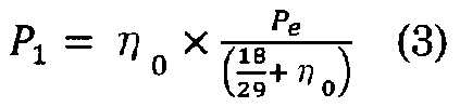
- the water vapor partial pressure P 1 of the EGR gas at the confluence point 33 in the equation (2) is determined by the absolute humidity ⁇ 0 [kg / kg] of the EGR gas at the outlet of the EGR water mist catcher 44 and the pressure of the EGR gas at the confluence point 33. It can be calculated by the following formula (3) using P e [Pa]. Among these, the value acquired in step S1 can be used as the pressure P e of the EGR gas at the junction 33. The pressure P e of the EGR gas at the confluence point 33 may use the value of the pressure P s of the scavenging gas.
- the absolute humidity ⁇ 0 of the EGR gas at the outlet of the EGR water mist catcher 44 is expressed as follows using the water vapor pressure P 0 [Pa] and the pressure P g [Pa] of the EGR gas at the outlet of the EGR water mist catcher 44: It can be calculated by equation (4). Among them, the pressure P g of the EGR gas at the outlet of the EGR water mist catcher 44 may be a value obtained in step S1.
- the water vapor pressure P 0 of the EGR gas at the outlet of the EGR water mist catcher 44 is expressed by the following equation (5) (Tetens equation) using the temperature T g [° C.] of the EGR gas at the outlet of the EGR water mist catcher 44. ).
- Temperature T g of the EGR gas at the outlet of the EGR water mist catcher 44 may be a value obtained in step S1.
- the dew point temperature T e may be calculated by a method other than the above.
- the dew point temperature T e as long as it greater such as about 2 ° C than the temperature T g of the EGR gas at the outlet of the EGR water mist catcher 44 is found empirically, EGR gas at the outlet of the EGR water mist catcher 44 value obtained by adding 2 ° C to a temperature T g of the may be used as the dew-point temperature T e.
- the control unit 50 determines a value obtained by subtracting the dew point temperature T e from the fresh air temperature T a is whether greater than a predetermined first lower limit value (e.g., 2 ° C) (step S3).
- a predetermined first lower limit value e.g. 2 ° C
- the fresh air temperature T a is higher than the dew point temperature T e, and determines whether the difference is greater than the first lower limit value. If the value obtained by subtracting the dew point temperature T e from the fresh air temperature T a is greater than the first lower limit (YES in step S3), the process proceeds to step S5.
- the EGR gas is combined with the fresh air, (because there is room) temperature of the EGR gas even as they fell to fresh air temperature T a, the temperature for a certain degree higher than the dew-point temperature T e of the EGR gas No condensation occurs due to the EGR gas joining with fresh air.
- the control unit 50 controls the EGR gas cooler 43 to lower the temperature of the EGR gas at the outlet of the EGR gas cooler 43 (step S4). As a result, the dew point temperature T e is reduced, it is possible to avoid condensation due to the EGR gas is combined with the fresh air.
- step S5 the second lower limit value minus the dew point temperature T e from the temperature T s of the scavenging gas is predetermined (e.g., 2 ° C) determines greater or not than. If the value obtained by subtracting the dew point temperature T e from the temperature T s of the scavenging gas is greater than the second lower limit value (YES in step S5), there is no danger of condensation by the EGR gas is in contact with the scavenging gas. In this case, the process proceeds to step S6.
- the first lower limit value and the second lower limit value may be the same value or different values. Further, the first lower limit value and the second lower limit value may be zero.
- the control unit 50 controls the EGR gas cooler 43 to lower the temperature of the EGR gas at the outlet of the EGR gas cooler 43 (step S4).
- dew point temperature T e is reduced, it is possible to EGR gas to avoid condensation caused by contact with the scavenging gas.
- step S6 it determines the value obtained by subtracting the dew point temperature T e from the fresh air temperature T a is whether less than a predetermined first upper limit value (e.g., 5 ° C). In other words, it is determined whether or not the dew-point temperature T e is not too low than the fresh air temperature T a. Since the value obtained by subtracting the dew point temperature T e from the fresh air temperature T a is not smaller than the first upper limit value (large) (NO in step S6), and thus dew point temperature T e is less than necessary, the control unit 50 controls the EGR gas cooler 43 to increase the temperature of the EGR gas at the outlet of the EGR gas cooler 43 (step S7). Thereby, the consumption of energy for cooling the EGR gas in the EGR gas cooler 43 can be suppressed.
- a predetermined first upper limit value e.g., 5 ° C
- step S6 it is determined whether or not the value obtained by subtracting the dew point temperature T e from the temperature T s of the scavenging gas is smaller than a predetermined second upper limit value (e.g., 5 ° C).
- a predetermined second upper limit value e.g., 5 ° C
- control The unit 50 controls the EGR gas cooler 43 to increase the temperature of the EGR gas at the outlet of the EGR gas cooler 43 (step S7).
- the first upper limit value and the second upper limit value may be the same value or different values. However, the first upper limit value is larger than the first lower limit value, and the second upper limit value is larger than the second lower limit value.
- step S8 When the value obtained by subtracting from the temperature T s of the dew-point temperature T e of the scavenging gas is smaller than the second upper limit value (YES in step S8), it returns to step S1 to repeat the steps S1 to S8. Similarly, when the temperature of the EGR gas at the outlet of the EGR gas cooler 43 is decreased in step S4, and when the temperature of the EGR gas at the outlet of the EGR gas cooler 43 is increased in step S7, the process returns to step S1. Repeat S1 to S8.
- control unit 50 can maintain a state (non-condensed state) in which the EGR gas does not have a possibility of condensing even when it comes into contact with fresh air or scavenging gas, and in the EGR gas cooler 43 Unnecessary energy consumption can be suppressed.
- step S4 of the control unit 50 controls the air cooler 31, by increasing the fresh air temperature (new air temperature) T a at the outlet of the air cooler 31, EGR gas is fresh air or An uncondensed state that does not condense even when contacted with the scavenging gas can be maintained.
- the control unit 50 controls only the EGR gas cooler 43 and only controls the EGR gas cooler 43 when the non-condensing state can be maintained only by controlling the EGR gas cooler 43 (within the range of the maximum cooling capacity of the EGR gas cooler 43). If the uncondensed state cannot be maintained, both the EGR gas cooler 43 and the air cooler 31 may be controlled. According to this configuration, since it controls the fresh air temperature T a to prevent as much as possible is increased, it is possible to suppress deterioration in fuel consumption of the engine body 10.
- the EGR gas cooler 43 is disposed downstream of the scrubber 42, but the EGR gas cooler 43 may be disposed upstream of the scrubber 42. Further, the EGR unit 40 may have a plurality of scrubbers 42 or may have a plurality of EGR gas coolers 43. For example, a first-stage scrubber 42 (prescrubber) may be provided upstream of the EGR gas cooler 43, and a second-stage scrubber 42 (main scrubber) may be provided downstream of the EGR gas cooler 43. Even with this configuration, if measuring the temperature T g and the pressure P g of the EGR gas can be controlled similar to the control described above.
- control part 50 demonstrated the case where the air cooler 31, the EGR gas cooler 43, or both were controlled, this control may be performed by the operator. That is, the control unit 50 may warn an operator when the EGR gas may condense, and the operator may control the air cooler 31, the EGR gas cooler 43, or both.
Landscapes
- Engineering & Computer Science (AREA)
- Chemical & Material Sciences (AREA)
- Combustion & Propulsion (AREA)
- Mechanical Engineering (AREA)
- General Engineering & Computer Science (AREA)
- Physics & Mathematics (AREA)
- Thermal Sciences (AREA)
- Chemical Kinetics & Catalysis (AREA)
- Exhaust-Gas Circulating Devices (AREA)
- Combined Controls Of Internal Combustion Engines (AREA)
Abstract
本発明の一態様に係るエンジンシステムは、掃気流路に設けられ新気を冷却するエアクーラと、EGR流路に設けられEGRガスを洗浄液で洗浄するスクラバと、EGR流路に設けられEGRガスを冷却するEGRガスクーラと、掃気流路に供給されるEGRガスの露点温度が、当該EGRガスと合流する新気の温度よりも低く、かつ、エンジン本体に供給される掃気ガスの温度よりも低い不凝結状態を維持するように、エアクーラ、EGRガスクーラ、又はその両方を制御する制御部と、を備えている。
Description
本発明はエンジンシステム及び制御方法に関する。
排気ガスをエンジンに再循環させる排気再循環(Exhaust Gas Recirculation;EGR)技術は、NOx排出低減効果が大きく、低環境負荷エンジンに広く適用されている。このEGRは、舶用の大型ディーゼルエンジンにおいても有効である。ただし、重油を燃料とする舶用の大型ディーゼルエンジンは、排気ガスに多くのSOxが含まれることから、排気ガスを再循環させる際には、その排気ガス(EGRガス)をスクラバによって洗浄するのが一般的である(特許文献1参照)。
EGRガスの洗浄は洗浄液を用いて行われるため、スクラバを通過したEGRガスは飽和状態となる。そのため、EGRガスが新気と合流して接触すると温度が低下して凝結し、凝縮水が発生することがある。さらに、スクラバによる洗浄ではEGRガスから完全にSOxを取り除くことは難しく、EGRガスにはSOxがわずかに含まれる。このEGRガスに含まれるSOxが上記の凝縮水に溶け込むと、掃気流路内に硫酸ミストが発生する。そして、硫酸ミストがエンジンに流入した場合には、エンジン内の腐食が進行しやすくなり、また、シリンダライナの異常摩擦が発生するという問題が生じる。
なお、掃気流路にウォータミストキャッチャを設け、ウォータミストキャッチャによって硫酸ミストを捕集することもできるが、硫酸ミストのうち極微小粒径のものは、ウォータミストキャッチャで捕集することができず、エンジンへ流入してしまう。また、新気と混合されていないEGRガスが、ウォータミストキャッチャよりも下流において掃気ガスに接触して凝結し、凝縮水が発生する場合もある。
本発明は、以上のような事情に鑑みてなされたものであり、EGRガスの凝結による凝縮水の発生を抑制できるエンジンシステムの提供を目的としている。
本発明の一態様に係るエンジンシステムは、エンジン本体と、前記エンジン本体から排出された排気ガスを外部に放出する排気流路と、新気にEGRガスを混合した掃気ガスを前記エンジン本体に供給する掃気流路と、前記排気流路から抽出した排気ガスをEGRガスとして前記掃気流路に供給するEGR流路と、前記掃気流路に設けられ新気を冷却するエアクーラと、前記EGR流路に設けられEGRガスを洗浄液で洗浄するスクラバと、前記EGR流路に設けられEGRガスを冷却するEGRガスクーラと、前記掃気流路に供給されるEGRガスの露点温度が、当該EGRガスと合流する新気の温度よりも低く、かつ、前記エンジン本体に供給される掃気ガスの温度よりも低い不凝結状態を維持するように、前記エアクーラ、前記EGRガスクーラ、又はその両方を制御する制御部と、を備えている。
この構成によれば、掃気流路に供給されるEGRガスの露点温度が、当該EGRガスと合流する新気の温度よりも低く、かつ、エンジン本体に供給される掃気ガスの温度よりも低くなるよう制御が行われるため、掃気流路に供給されるEGRガスが新気又は掃気ガスと接触したときに、EGRガスが凝結して凝縮水が発生するのを抑えることができる。
また、上記のエンジンシステムにおいて、前記制御部は、前記不凝結状態を維持するとともに、EGRガスと合流する新気の温度と前記掃気流路に供給されるEGRガスの露点温度の差が所定の第1上限値を超えないように、かつ、前記エンジン本体に供給される掃気ガスの温度と前記掃気流路に供給されるEGRガスの露点温度の差が所定の第2上限値を超えないように、前記エアクーラ、前記EGRガスクーラ、又はその両方を制御するようにしてもよい。
この構成によれば、EGRガスと合流する新気の温度と掃気流路に供給されるEGRガスの露点温度の差が所定の第1上限値を超えないように、かつ、エンジン本体に供給される掃気ガスの温度と掃気流路に供給されるEGRガスの露点温度の差が所定の第2上限値を超えないように制御が行われるため、EGRガスを過剰に冷却するのを防いでEGRガスを冷却するためのエネルギの不要な消費を抑えることができ、また、新気の温度の過剰な上昇を防いで燃費の低下を抑えることができる。
また、上記のエンジンシステムにおいて、前記制御部は、前記EGRガスクーラの制御のみで前記不凝結状態を維持できる場合には前記EGRガスクーラのみを制御し、前記EGRガスクーラの制御のみで前記不凝結状態を維持できない場合には前記EGRガスクーラ及び前記エアクーラの両方を制御するようにしてもよい。
この構成によれば、EGRガスクーラの制御のみで不凝結状態を維持できる場合にはEGRガスクーラのみを制御するため、可能な限りエアクーラの制御を避けて、新気の温度上昇を防ぐことによりエンジン本体の燃費の低下を抑えることができる。
また、本発明の他の態様に係るエンジンシステムは、エンジン本体と、前記エンジン本体から排出された排気ガスを外部に放出する排気流路と、新気にEGRガスを混合した掃気ガスを前記エンジン本体に供給する掃気流路と、前記排気流路から抽出した排気ガスをEGRガスとして前記掃気流路に供給するEGR流路と、前記掃気流路に設けられ新気を冷却するエアクーラと、前記EGR流路に設けられEGRガスを洗浄液で洗浄するスクラバと、前記EGR流路に設けられEGRガスを冷却するEGRガスクーラと、EGRガスと合流する新気の温度と前記掃気流路に供給されるEGRガスの露点温度の差が所定の第1下限値以下となったとき、又は、前記エンジン本体に供給される掃気ガスの温度と前記掃気流路に供給されるEGRガスの露点温度の差が所定の第2下限値以下となったとき、所定の警報信号を発信する制御部と、を備えている。
この構成によれば、EGRガスが新気又は掃気ガスと接触することで凝結するおそれがある場合、制御部が警報信号を発信することになる。これにより、警報によってEGRガスが凝結するおそれがあることを知った作業者は、エアクーラ、EGRガスクーラ、又はその両方を例えば手動バルブによって冷却水の流量を制御することで、EGRガスの凝結による凝縮水の発生を事前に防ぐことができる。
さらに、本発明の一態様に係る制御方法は、エンジン本体と、前記エンジン本体から排出された排気ガスを外部に放出する排気流路と、新気にEGRガスを混合した掃気ガスを前記エンジン本体に供給する掃気流路と、前記排気流路から抽出した排気ガスをEGRガスとして前記掃気流路に供給するEGR流路と、前記掃気流路に設けられ新気を冷却するエアクーラと、前記EGR流路に設けられEGRガスを洗浄液で洗浄するスクラバと、前記EGR流路に設けられEGRガスを冷却するEGRガスクーラと、を備えたエンジンシステムの制御方法であって、前記掃気流路に供給されるEGRガスの露点温度が、当該EGRガスと合流する新気の温度よりも低く、かつ、前記エンジン本体に供給される掃気ガスの温度よりも低い不凝結状態を維持するように、前記エアクーラ、前記EGRガスクーラ、又はその両方を制御する。
以上のとおり、上記のエンジンシステムによれば、EGRガスの凝結による凝縮水の発生を抑制することができる。
以下、本発明の実施形態について図を参照しながら説明する。以下では、全ての図面を通じて同一又は相当する要素には同じ符号を付して、重複する説明は省略する。
<エンジンシステムの全体構成>
はじめに、実施形態に係るエンジンシステム100の全体構成について説明する。図1は、エンジンシステム100の全体構成図である。図1において、太く描いた破線は排気ガス又はEGRガスの流れを示しており、太く描いた実線は掃気ガス又は新気ガスの流れを示している。
はじめに、実施形態に係るエンジンシステム100の全体構成について説明する。図1は、エンジンシステム100の全体構成図である。図1において、太く描いた破線は排気ガス又はEGRガスの流れを示しており、太く描いた実線は掃気ガス又は新気ガスの流れを示している。
本実施形態に係るエンジンシステム100は舶用のエンジンシステムであって、エンジン本体10と、排気流路20と、掃気流路30と、EGRユニット40と、制御部50と、を備えている。以下、これらの各構成要素について順に説明する。
本実施形態のエンジン本体10は、いわゆる2ストロークディーゼルエンジンである。エンジン本体10には、掃気管11を介して掃気流路30から掃気ガスが供給される。掃気管11は一時的に掃気ガスを収容するように構成されており、掃気管11には掃気ガスの温度Tsを測定する掃気ガス温度センサ12、及び、掃気ガスの圧力Psを測定する掃気ガス圧力センサ13が設けられている。また、エンジン本体10から排出された排気ガスは、排気管14に一時的に収容され、排気管14から排気流路20へと排出される。
排気流路20は、エンジン本体10から排出された排気ガスを外部に放出する流路である。排気流路20上には、過給機21のタービン部22が設けられており、排気ガスのエネルギによりタービン部22は回転する。タービン部22は連結軸23を介して掃気流路30上に設けられたコンプレッサ部24に連結されている。そのため、タービン部22が回転すると、これに伴ってコンプレッサ部24も回転する。コンプレッサ部24が回転することにより、外部から取り込んだ新気が圧縮される。
掃気流路30は、エンジン本体10に掃気ガスを供給する流路である。掃気流路30には、過給機21により圧縮された新気を冷却するためのエアクーラ31が設けられているとともに、エアクーラ31の下流にはエアクーラ31の出口における新気の温度Taを測定するエア温度センサ32が設けられている。エアクーラ31内には冷却水が流れており、この冷却水の流量及び温度を制御することで、エアクーラ31の出口における新気の温度Taを調整することができる。
エアクーラ31を通過した新気は、掃気流路30の合流点33において、EGRユニット40を通過したEGRガスと合流し、新気とEGRガスが混合されて掃気ガスが生成される。また、掃気流路30の合流点33には、合流点33におけるEGRガスの圧力Peを測定する合流点圧力センサ34が設けられている。さらに、掃気流路30の合流点33よりも下流側には、掃気流路30を通過する水滴を捕集するウォータミストキャッチャ35が設けられている。なお、前述のとおり極微小径の水滴は、ウォータミストキャッチャ35で捕集できない場合もある。
EGRユニット40は、排気流路20から排気ガスの一部を抽出し、その排気ガスをEGRガスとして掃気流路30に供給するユニットである。EGRユニット40は、排気流路20のタービン部22の位置よりも上流側の部分と掃気流路30のコンプレッサ部24及びエアクーラ31の位置よりも下流側の部分をつなぐEGR流路41を有している。EGR流路51には上流側から順に、洗浄液を用いてEGRガスを洗浄するスクラバ42、スクラバ42で洗浄したEGRガスを冷却するEGRガスクーラ43、EGRガスクーラ43で発生した凝縮水を捕集するEGRウォータミストキャッチャ44、EGRガスを昇圧するとともに掃気流路30に供給するEGRガスの流量を調整するEGRブロワ55が設けられている。
さらに、EGRウォータミストキャッチャ44の下流には、EGRウォータミストキャッチャ44の出口におけるEGRガスの温度Tg及び圧力Pgをそれぞれ測定するEGRガス温度センサ46及びEGRガス圧力センサ47が設けられている。また、EGRガスクーラ43内には冷却水が流れており、この冷却水の流量及び温度を制御することで、EGRガスクーラ43の出口におけるEGRガスの温度を調整することができる。
なお、前述のとおり、スクラバ52は、洗浄液を用いてEGRガスからSOx及びばいじんを取り除くが、EGRガスに含まれるSOxを完全に取り除くことは実質的に不可能である。そのため、掃気流路30に供給されるEGRガスには、わずかにSOxが含まれており、このSOxが掃気流路30内の水滴に溶け込むと硫酸ミストが発生する。
制御部50は、エンジンシステム100全体を制御する部分であって、CPU、ROM、RAM等によって構成されている。図2は、エンジンシステム100の制御系のブロック図である。図2に示すように、制御部50は、掃気ガス温度センサ12、掃気ガス圧力センサ13、エア温度センサ32、合流点圧力センサ34、EGRガス温度センサ46、及びEGRガス圧力センサ47と電気的に接続されている。制御部50は、これらの機器から送信される測定信号に基づいて、それぞれ掃気ガスの温度Ts、掃気ガスの圧力Ps、エアクーラ31の出口における新気の温度(以下、「新気温度」という)Ta、合流点33におけるEGRガスの圧力Pe、EGRウォータミストキャッチャ44の出口におけるEGRガスの温度Tg、及びEGRウォータミストキャッチャ44の出口におけるEGRガスの圧力Pgの各種測定値を取得することができる。
さらに、制御部50は、取得した各種測定値に基づいて種々の演算を行い、エンジンシステム100全体を制御する。本実施形態では、制御部50は、エアクーラ31、及びEGRガスクーラ43と電気的に接続されており、種々の演算等の結果に基づいて、これらの機器へ制御信号を送信し、新気の温度及びEGRガスの温度を調整する。具体的には、制御部50は、EGRガスが新気又は掃気ガスに接触することで冷却され、その結果、凝結して凝縮水が発生することがないように制御を行う。より具体的な制御内容については後述する。
<制御内容>
次に、制御部50による制御の内容について説明する。図3は、制御部50による制御の流れを示したフローチャートである。図3に示すように制御が開始されると、まず制御部50は各種センサから測定信号を受信し、これらの測定信号に基づいて各種測定値を取得する(ステップS1)。
次に、制御部50による制御の内容について説明する。図3は、制御部50による制御の流れを示したフローチャートである。図3に示すように制御が開始されると、まず制御部50は各種センサから測定信号を受信し、これらの測定信号に基づいて各種測定値を取得する(ステップS1)。
続いて、制御部50は、ステップS1で取得した各種測定値に基づいて、合流点33におけるEGRガスの露点温度(以下、単に「露点温度」という)Teを算出する。露点温度Te[°C]は、以下の式(1)で算出することができる。なお、以降の式では、EGRウォータミストキャッチャ44の出口におけるEGRガスが飽和水蒸気(湿度100%RH)であると仮定している。

上記の式(1)におけるyは、合流点33におけるEGRガスの水蒸気分圧P1[Pa]を用いて以下の式(2)で表される。

また、式(2)の合流点33におけるEGRガスの水蒸気分圧P1は、EGRウォータミストキャッチャ44の出口におけるEGRガスの絶対湿度η0[kg/kg]及び合流点33におけるEGRガスの圧力Pe[Pa]を用いて、以下の式(3)で算出することができる。このうち、合流点33におけるEGRガスの圧力Peは、ステップS1で取得した値を用いることができる。なお、合流点33におけるEGRガスの圧力Peは、掃気ガスの圧力Psの値を用いてもよい。
また、EGRウォータミストキャッチャ44の出口におけるEGRガスの絶対湿度η0は、EGRウォータミストキャッチャ44の出口におけるEGRガスの水蒸気圧P0[Pa]及び圧力Pg[Pa]を用いて、以下の式(4)で算出することができる。このうち、EGRウォータミストキャッチャ44の出口におけるEGRガスの圧力Pgは、ステップS1で取得した値を用いることができる。

また、EGRウォータミストキャッチャ44の出口におけるEGRガスの水蒸気圧P0は、EGRウォータミストキャッチャ44の出口におけるEGRガスの温度Tg[°C]を用いて以下の式(5)(Tetensの式)で算出することができる。EGRウォータミストキャッチャ44の出口におけるEGRガスの温度Tgは、ステップS1で取得した値を用いることができる。

以上のとおり、ステップS1で取得した各種測定値と上記の式(1)乃至式(5)を用いれば、露点温度Teを算出することができる。ただし、露点温度Teは上記以外の方法で算出してもよい。例えば、露点温度Teは、EGRウォータミストキャッチャ44の出口におけるEGRガスの温度Tgよりも例えば約2°C高いことが経験上判明していれば、EGRウォータミストキャッチャ44の出口におけるEGRガスの温度Tgに2°Cを加えた値を露点温度Teとしてもよい。また、本実施形態では、露点温度Teの算出にあたり、EGRウォータミストキャッチャ44の出口におけるEGRガスの温度Tg及び圧力Pgを用いているが、これに代えて例えばEGRウォータミストキャッチャ44の入口におけるEGRガスの温度及び圧力を用いてもよい。
続いて、制御部50は、新気温度Taから露点温度Teを引いた値が所定の第1下限値(例えば2°C)よりも大きいか否かを判定する(ステップS3)。つまり、新気温度Taが露点温度Teよりも高く、かつ、その差が第1下限値よりも大きいか否かを判定する。新気温度Taから露点温度Teを引いた値が第1下限値よりも大きい場合は(ステップS3においてYES)、ステップS5へ進む。この場合、EGRガスが新気と合流して、EGRガスの温度が新気温度Taまで下がったとしても、その温度はEGRガスの露点温度Teよりもある程度高いため(余裕があるため)、EGRガスが新気と合流することによる凝結は生じない。
一方、新気温度Taから露点温度Teを引いた値が第1下限値よりも大きくない場合(ステップS3においてNO)、EGRガスが新気と合流したときにEGRガスが凝結して凝縮水が発生するおそれがある。この場合、制御部50は、EGRガスクーラ43を制御して、EGRガスクーラ43の出口におけるEGRガスの温度を低下させる(ステップS4)。これにより、露点温度Teは低下し、EGRガスが新気と合流することによる凝結を回避することができる。
ステップS5では、掃気ガスの温度Tsから露点温度Teを引いた値が所定の第2下限値(例えば、2°C)よりも大きいか否かを判定する。掃気ガスの温度Tsから露点温度Teを引いた値が第2下限値よりも大きい場合は(ステップS5においてYES)、EGRガスが掃気ガスと接触することによって凝結するおそれはない。この場合、ステップS6へ進む。なお、第1下限値及び第2下限値は互いに同じ値であってもよく、別の値であってもよい。また、第1下限値及び第2下限値はゼロであってもよい。
一方、掃気ガスの温度Tsから露点温度Teを引いた値が所定の下限値よりも大きくない場合(ステップS5においてNO)、EGRガスが掃気ガスと接触したときにEGRガスが凝結するおそれがある。この場合、制御部50は、EGRガスクーラ43を制御して、EGRガスクーラ43の出口におけるEGRガスの温度を低下させる(ステップS4)。これにより、露点温度Teは低下し、EGRガスが掃気ガスと接触することによる凝結を回避することができる。
ステップS6では、新気温度Taから露点温度Teを引いた値が所定の第1上限値(例えば5°C)よりも小さいか否かを判定する。つまり、露点温度Teが新気温度Taよりも低すぎないか否かを判定する。新気温度Taから露点温度Teを引いた値が第1上限値よりも小さくない(大きい)場合(ステップS6においてNO)、必要以上に露点温度Teが低いことになるため、制御部50はEGRガスクーラ43を制御して、EGRガスクーラ43の出口におけるEGRガスの温度を上昇させる(ステップS7)。これにより、EGRガスクーラ43におけるEGRガスを冷却するためのエネルギの消費を抑えることができる。
一方、新気温度Taから露点温度Teを引いた値が所定の第1上限値よりも小さい場合(ステップS6においてYES)、ステップS8へ進む。ステップS8では、掃気ガスの温度Tsから露点温度Teを引いた値が所定の第2上限値(例えば5°C)よりも小さいか否かを判定する。掃気ガスの温度Tsから露点温度Teを引いた値が第2上限値よりも小さくない(大きい)場合(ステップS8においてNO)、必要以上に露点温度Teが低いことになるため、制御部50はEGRガスクーラ43を制御して、EGRガスクーラ43の出口におけるEGRガスの温度を上昇させる(ステップS7)。なお、第1上限値及び第2上限値は互いに同じ値であってもよく、別の値であってもよい。ただし、第1上限値は第1下限値よりも大きく、第2上限値は第2下限値よりも大きい。
また、掃気ガスの温度Tsから露点温度Teを引いた値が第2上限値よりも小さい場合(ステップS8においてYES)、ステップS1に戻ってステップS1乃至S8を繰り返す。同様に、ステップS4においてEGRガスクーラ43の出口におけるEGRガスの温度を低下させた場合、及び、ステップS7においてEGRガスクーラ43の出口におけるEGRガスの温度を上昇させた場合も、ステップS1に戻ってステップS1乃至S8を繰り返す。
制御部50は、上記の制御を行うことにより、EGRガスが新気又は掃気ガスと接触しても凝結するおそれのない状態(不凝結状態)を維持することができ、かつ、EGRガスクーラ43において不要なエネルギの消費を抑えることができる。
なお、上述した制御では、ステップS4においてEGRガスクーラ43のみを制御していたが、EGRガスクーラ43のみの制御に代えて又はEGRガスクーラ43の制御とともにエアクーラ31を制御してもよい。具体的には、上記のステップS4において、制御部50はエアクーラ31を制御し、エアクーラ31の出口における新気の温度(新気温度)Taを上昇させることによっても、EGRガスが新気又は掃気ガスと接触しても凝結しない不凝結状態を維持することができる。
ただし、新気温度Taを上昇させると、エンジン本体10の燃費が低下する。そのため、制御部50は、EGRガスクーラ43の制御のみで(EGRガスクーラ43の最大冷却能力の範囲内で)不凝結状態を維持できる場合にはEGRガスクーラ43のみを制御し、EGRガスクーラ43の制御のみで不凝結状態を維持できない場合にはEGRガスクーラ43及びエアクーラ31の両方を制御するようにしてもよい。この構成によれば、新気温度Taを極力上昇させないように制御できるため、エンジン本体10の燃費の低下を抑えることができる。
また、上記のEGRユニット40では、スクラバ42の下流にEGRガスクーラ43が配置されていたが、スクラバ42の上流にEGRガスクーラ43を配置してもよい。さらに、EGRユニット40は、複数のスクラバ42を有していてもよく、複数のEGRガスクーラ43を有していてもよい。例えば、EGRガスクーラ43の上流に1段目のスクラバ42(プリスクラバ)を設け、EGRガスクーラ43の下流に2段目のスクラバ42(メインスクラバ)を設けてもよい。このような構成であっても、EGRガスの温度Tg及び圧力Pgを測定できれば、前述した制御と同様の制御を行うことができる。
なお、上記の実施形態では、制御部50がエアクーラ31、EGRガスクーラ43、又はその両方を制御する場合について説明したが、この制御は作業者が行ってもよい。つまり、制御部50はEGRガスが凝結する可能性があるときに作業者に警告し、作業者がエアクーラ31、EGRガスクーラ43、又はその両方を制御するようにしてもよい。具体的には、制御部50は、EGRガスと合流する新気の温度と掃気流路30に供給されるEGRガスの露点温度の差が所定の第1下限値以下となったとき、又は、エンジン本体10に供給される掃気ガスの温度と掃気流路30に供給されるEGRガスの露点温度の差が所定の第2下限値以下となったとき、スピーカやディスプレイなどの報知機器に警報信号を発信してもよい。すなわち、図3のステップS3及びS5においてNOのとき、制御部50はステップS4で所定の警報信号を発信するようにしてもよい。この場合であっても、作業者によるバルブ等の制御(操作)によって、EGRガスの凝結による凝縮水の発生を事前に防ぐことができる。
10 エンジン本体
20 排気流路
30 掃気流路
31 エアクーラ
35 ウォータミストキャッチャ
41 EGR流路
42 スクラバ
43 EGRガスクーラ
50 制御部
100 エンジンシステム
20 排気流路
30 掃気流路
31 エアクーラ
35 ウォータミストキャッチャ
41 EGR流路
42 スクラバ
43 EGRガスクーラ
50 制御部
100 エンジンシステム
Claims (5)
- エンジン本体と、
前記エンジン本体から排出された排気ガスを外部に放出する排気流路と、
新気にEGRガスを混合した掃気ガスを前記エンジン本体に供給する掃気流路と、
前記排気流路から抽出した排気ガスをEGRガスとして前記掃気流路に供給するEGR流路と、
前記掃気流路に設けられ新気を冷却するエアクーラと、
前記EGR流路に設けられEGRガスを洗浄液で洗浄するスクラバと、
前記EGR流路に設けられEGRガスを冷却するEGRガスクーラと、
前記掃気流路に供給されるEGRガスの露点温度が、当該EGRガスと合流する新気の温度よりも低く、かつ、前記エンジン本体に供給される掃気ガスの温度よりも低い不凝結状態を維持するように、前記エアクーラ、前記EGRガスクーラ、又はその両方を制御する制御部と、を備えたエンジンシステム。 - 前記制御部は、前記不凝結状態を維持するとともに、EGRガスと合流する新気の温度と前記掃気流路に供給されるEGRガスの露点温度の差が所定の第1上限値を超えないように、かつ、前記エンジン本体に供給される掃気ガスの温度と前記掃気流路に供給されるEGRガスの露点温度の差が所定の第2上限値を超えないように、前記エアクーラ、前記EGRガスクーラ、又はその両方を制御する請求項1に記載のエンジンシステム。
- 前記制御部は、前記EGRガスクーラの制御のみで前記不凝結状態を維持できる場合には前記EGRガスクーラのみを制御し、前記EGRガスクーラの制御のみで前記不凝結状態を維持できない場合には前記EGRガスクーラ及び前記エアクーラの両方を制御する、請求項1又は2に記載のエンジンシステム。
- エンジン本体と、
前記エンジン本体から排出された排気ガスを外部に放出する排気流路と、
新気にEGRガスを混合した掃気ガスを前記エンジン本体に供給する掃気流路と、
前記排気流路から抽出した排気ガスをEGRガスとして前記掃気流路に供給するEGR流路と、
前記掃気流路に設けられ新気を冷却するエアクーラと、
前記EGR流路に設けられEGRガスを洗浄液で洗浄するスクラバと、
前記EGR流路に設けられEGRガスを冷却するEGRガスクーラと、
EGRガスと合流する新気の温度と前記掃気流路に供給されるEGRガスの露点温度の差が所定の第1下限値以下となったとき、又は、前記エンジン本体に供給される掃気ガスの温度と前記掃気流路に供給されるEGRガスの露点温度の差が所定の第2下限値以下となったとき、所定の警報信号を発信する制御部と、を備えたエンジンシステム。 - エンジン本体と、
前記エンジン本体から排出された排気ガスを外部に放出する排気流路と、
新気にEGRガスを混合した掃気ガスを前記エンジン本体に供給する掃気流路と、
前記排気流路から抽出した排気ガスをEGRガスとして前記掃気流路に供給するEGR流路と、
前記掃気流路に設けられ新気を冷却するエアクーラと、
前記EGR流路に設けられEGRガスを洗浄液で洗浄するスクラバと、
前記EGR流路に設けられEGRガスを冷却するEGRガスクーラと、を備えたエンジンシステムの制御方法であって、
前記掃気流路に供給されるEGRガスの露点温度が、当該EGRガスと合流する新気の温度よりも低く、かつ、前記エンジン本体に供給される掃気ガスの温度よりも低い不凝結状態を維持するように、前記エアクーラ、前記EGRガスクーラ、又はその両方を制御する、制御方法。
Priority Applications (2)
| Application Number | Priority Date | Filing Date | Title |
|---|---|---|---|
| KR1020187028570A KR102061733B1 (ko) | 2016-03-07 | 2017-03-02 | 엔진 시스템 및 제어 방법 |
| CN201780008899.3A CN108495993B (zh) | 2016-03-07 | 2017-03-02 | 发动机系统及控制方法 |
Applications Claiming Priority (2)
| Application Number | Priority Date | Filing Date | Title |
|---|---|---|---|
| JP2016-043478 | 2016-03-07 | ||
| JP2016043478A JP6633944B2 (ja) | 2016-03-07 | 2016-03-07 | エンジンシステム及び制御方法 |
Publications (1)
| Publication Number | Publication Date |
|---|---|
| WO2017154716A1 true WO2017154716A1 (ja) | 2017-09-14 |
Family
ID=59789251
Family Applications (1)
| Application Number | Title | Priority Date | Filing Date |
|---|---|---|---|
| PCT/JP2017/008224 Ceased WO2017154716A1 (ja) | 2016-03-07 | 2017-03-02 | エンジンシステム及び制御方法 |
Country Status (4)
| Country | Link |
|---|---|
| JP (1) | JP6633944B2 (ja) |
| KR (1) | KR102061733B1 (ja) |
| CN (1) | CN108495993B (ja) |
| WO (1) | WO2017154716A1 (ja) |
Cited By (1)
| Publication number | Priority date | Publication date | Assignee | Title |
|---|---|---|---|---|
| WO2025227664A1 (zh) * | 2024-04-30 | 2025-11-06 | 佛山市顺德区美的洗涤电器制造有限公司 | 洗涤设备干燥控制方法、装置、设备及可读存储介质 |
Families Citing this family (5)
| Publication number | Priority date | Publication date | Assignee | Title |
|---|---|---|---|---|
| JP6964484B2 (ja) | 2017-10-30 | 2021-11-10 | 川崎重工業株式会社 | エンジンシステム |
| JP6550520B1 (ja) * | 2018-11-09 | 2019-07-24 | 川崎重工業株式会社 | Egrユニット及びエンジンシステム |
| KR102752466B1 (ko) * | 2019-03-29 | 2025-01-09 | 한화엔진 주식회사 | 배기가스 재순환 시스템 및 탈황 시스템을 포함한 동력 장치 |
| CN112796898B (zh) * | 2019-10-28 | 2022-08-02 | 浙江义利汽车零部件有限公司 | 一种防止水冷式冷却器下游混合气冷凝的方法及装置 |
| CN114856843B (zh) * | 2022-05-18 | 2023-05-23 | 潍柴动力股份有限公司 | 一种排气量计算方法、egr气量控制方法及egr系统 |
Citations (5)
| Publication number | Priority date | Publication date | Assignee | Title |
|---|---|---|---|---|
| JP2003201903A (ja) * | 2001-12-18 | 2003-07-18 | Detroit Diesel Corp | Egrを使用する内燃機関の凝縮制御方法およびシステム |
| JP2009174444A (ja) * | 2008-01-25 | 2009-08-06 | Honda Motor Co Ltd | Egr装置 |
| JP2011157959A (ja) * | 2010-01-29 | 2011-08-18 | Man Diesel & Turbo Filial Af Man Diesel & Turbo Se Tyskland | 排ガス再循環システムを備える大型2サイクルディーゼル機関 |
| JP2015174034A (ja) * | 2014-03-14 | 2015-10-05 | 川崎重工業株式会社 | スクラバ及びエンジンシステム |
| JP2015197078A (ja) * | 2014-04-02 | 2015-11-09 | 株式会社デンソー | 内燃機関のegrシステム |
Family Cites Families (11)
| Publication number | Priority date | Publication date | Assignee | Title |
|---|---|---|---|---|
| JP3669407B2 (ja) * | 1998-01-09 | 2005-07-06 | 三菱ふそうトラック・バス株式会社 | 排ガス再循環装置 |
| CN1635270A (zh) * | 2003-12-26 | 2005-07-06 | 臼井国际产业株式会社 | 排气再循环气体冷却机构 |
| JP4631886B2 (ja) * | 2007-08-28 | 2011-02-16 | トヨタ自動車株式会社 | 内燃機関の排気還流システム |
| US8015822B2 (en) * | 2008-11-21 | 2011-09-13 | General Electric Company | Method for controlling an exhaust gas recirculation system |
| JP5636615B2 (ja) | 2010-01-05 | 2014-12-10 | 株式会社イワキ | ポンプシステム |
| JP5787500B2 (ja) * | 2010-08-24 | 2015-09-30 | 三菱重工業株式会社 | エンジン排気ガス浄化装置及び船舶 |
| US8725386B2 (en) * | 2011-07-14 | 2014-05-13 | Southwest Research Institute | Effectiveness modeling and control methods for EGR cooler |
| US20140150758A1 (en) * | 2012-12-04 | 2014-06-05 | General Electric Company | Exhaust gas recirculation system with condensate removal |
| JP2014134154A (ja) * | 2013-01-10 | 2014-07-24 | Mitsubishi Heavy Ind Ltd | 船舶 |
| DE102013003001A1 (de) * | 2013-02-22 | 2014-08-28 | Man Diesel & Turbo Se | Brennkraftmaschine, Abgasrückführungsvorrichtung und Verfahren zur Abgasrückführung |
| JP6315246B2 (ja) | 2014-03-31 | 2018-04-25 | 富士紡ホールディングス株式会社 | 研磨パッド及びその製造方法 |
-
2016
- 2016-03-07 JP JP2016043478A patent/JP6633944B2/ja active Active
-
2017
- 2017-03-02 KR KR1020187028570A patent/KR102061733B1/ko active Active
- 2017-03-02 WO PCT/JP2017/008224 patent/WO2017154716A1/ja not_active Ceased
- 2017-03-02 CN CN201780008899.3A patent/CN108495993B/zh active Active
Patent Citations (5)
| Publication number | Priority date | Publication date | Assignee | Title |
|---|---|---|---|---|
| JP2003201903A (ja) * | 2001-12-18 | 2003-07-18 | Detroit Diesel Corp | Egrを使用する内燃機関の凝縮制御方法およびシステム |
| JP2009174444A (ja) * | 2008-01-25 | 2009-08-06 | Honda Motor Co Ltd | Egr装置 |
| JP2011157959A (ja) * | 2010-01-29 | 2011-08-18 | Man Diesel & Turbo Filial Af Man Diesel & Turbo Se Tyskland | 排ガス再循環システムを備える大型2サイクルディーゼル機関 |
| JP2015174034A (ja) * | 2014-03-14 | 2015-10-05 | 川崎重工業株式会社 | スクラバ及びエンジンシステム |
| JP2015197078A (ja) * | 2014-04-02 | 2015-11-09 | 株式会社デンソー | 内燃機関のegrシステム |
Cited By (1)
| Publication number | Priority date | Publication date | Assignee | Title |
|---|---|---|---|---|
| WO2025227664A1 (zh) * | 2024-04-30 | 2025-11-06 | 佛山市顺德区美的洗涤电器制造有限公司 | 洗涤设备干燥控制方法、装置、设备及可读存储介质 |
Also Published As
| Publication number | Publication date |
|---|---|
| JP6633944B2 (ja) | 2020-01-22 |
| JP2017160799A (ja) | 2017-09-14 |
| CN108495993B (zh) | 2021-05-25 |
| KR102061733B1 (ko) | 2020-01-02 |
| KR20180122661A (ko) | 2018-11-13 |
| CN108495993A (zh) | 2018-09-04 |
Similar Documents
| Publication | Publication Date | Title |
|---|---|---|
| JP6633944B2 (ja) | エンジンシステム及び制御方法 | |
| JP2009052440A (ja) | 舶用排ガス処理装置 | |
| US8046986B2 (en) | Method and system for controlling an exhaust gas recirculation system | |
| CN105189969B (zh) | 异常判定系统和异常判定方法 | |
| CN104564435B (zh) | 大型低速运行的涡轮增压二冲程内燃机 | |
| KR101698440B1 (ko) | Egr 유닛 및 선박 엔진 시스템 | |
| US9188037B2 (en) | Exhaust gas cooler | |
| JP4318055B2 (ja) | 硫黄酸化物を含む排ガスの処理方法およびその装置 | |
| SE531841C2 (sv) | Arrangemang och förfarande för återcirkulation av avgaser hos en förbränningsmotor | |
| JP2011157959A (ja) | 排ガス再循環システムを備える大型2サイクルディーゼル機関 | |
| CN104302901A (zh) | 异常检测方法 | |
| KR20160066601A (ko) | 인터쿨러 열화 진단 방법 | |
| EP2998563A1 (en) | Cleaning/cooling device, egr unit and engine system | |
| WO2017029937A1 (ja) | 油冷式スクリュ圧縮機及びその制御方法 | |
| WO2014109339A1 (ja) | 船舶 | |
| JP2009041551A (ja) | 内燃機関の排気還流装置 | |
| KR20170030027A (ko) | 내연 엔진용 배기 가스 재순환 시스템, 내연 엔진, 내연 엔진의 배기 가스 재순환 과정을 모니터링하기 위한 방법, 배기 가스 재순환 시스템을 개장하기 위한 방법, 및 내연 엔진을 개장하기 위한 키트 | |
| JP2001041110A (ja) | Egrクーラ付きegr装置 | |
| JP5789321B2 (ja) | スクラバ及びエンジンシステム | |
| JP6567607B2 (ja) | 船舶および船舶推進用の内燃機関 | |
| JP5768502B2 (ja) | 流体流通部材の腐食検知システム | |
| JP2016084716A (ja) | 内燃機関 | |
| SE1750309A1 (sv) | Förfarande för övervakning av en metanoxidationskatalysator och en avgasreningsenhet. | |
| JP2016176409A (ja) | エンジンの排気再循環装置及びその制御方法 | |
| JP6156005B2 (ja) | エンジンのオイル劣化検知装置 |
Legal Events
| Date | Code | Title | Description |
|---|---|---|---|
| NENP | Non-entry into the national phase |
Ref country code: DE |
|
| ENP | Entry into the national phase |
Ref document number: 20187028570 Country of ref document: KR Kind code of ref document: A |
|
| 121 | Ep: the epo has been informed by wipo that ep was designated in this application |
Ref document number: 17763056 Country of ref document: EP Kind code of ref document: A1 |
|
| 122 | Ep: pct application non-entry in european phase |
Ref document number: 17763056 Country of ref document: EP Kind code of ref document: A1 |