WO2017154569A1 - 吸着式冷凍システム、および車両用の空調装置 - Google Patents
吸着式冷凍システム、および車両用の空調装置 Download PDFInfo
- Publication number
- WO2017154569A1 WO2017154569A1 PCT/JP2017/006491 JP2017006491W WO2017154569A1 WO 2017154569 A1 WO2017154569 A1 WO 2017154569A1 JP 2017006491 W JP2017006491 W JP 2017006491W WO 2017154569 A1 WO2017154569 A1 WO 2017154569A1
- Authority
- WO
- WIPO (PCT)
- Prior art keywords
- heat exchange
- exchange medium
- refrigerant
- adsorption
- circulation path
- Prior art date
- Legal status (The legal status is an assumption and is not a legal conclusion. Google has not performed a legal analysis and makes no representation as to the accuracy of the status listed.)
- Ceased
Links
Images



Classifications
-
- B—PERFORMING OPERATIONS; TRANSPORTING
- B60—VEHICLES IN GENERAL
- B60H—ARRANGEMENTS OF HEATING, COOLING, VENTILATING OR OTHER AIR-TREATING DEVICES SPECIALLY ADAPTED FOR PASSENGER OR GOODS SPACES OF VEHICLES
- B60H1/00—Heating, cooling or ventilating devices
- B60H1/32—Cooling devices
-
- F—MECHANICAL ENGINEERING; LIGHTING; HEATING; WEAPONS; BLASTING
- F25—REFRIGERATION OR COOLING; COMBINED HEATING AND REFRIGERATION SYSTEMS; HEAT PUMP SYSTEMS; MANUFACTURE OR STORAGE OF ICE; LIQUEFACTION SOLIDIFICATION OF GASES
- F25B—REFRIGERATION MACHINES, PLANTS OR SYSTEMS; COMBINED HEATING AND REFRIGERATION SYSTEMS; HEAT PUMP SYSTEMS
- F25B17/00—Sorption machines, plants or systems, operating intermittently, e.g. absorption or adsorption type
- F25B17/08—Sorption machines, plants or systems, operating intermittently, e.g. absorption or adsorption type the absorbent or adsorbent being a solid, e.g. salt
-
- F—MECHANICAL ENGINEERING; LIGHTING; HEATING; WEAPONS; BLASTING
- F25—REFRIGERATION OR COOLING; COMBINED HEATING AND REFRIGERATION SYSTEMS; HEAT PUMP SYSTEMS; MANUFACTURE OR STORAGE OF ICE; LIQUEFACTION SOLIDIFICATION OF GASES
- F25B—REFRIGERATION MACHINES, PLANTS OR SYSTEMS; COMBINED HEATING AND REFRIGERATION SYSTEMS; HEAT PUMP SYSTEMS
- F25B27/00—Machines, plants or systems, using particular sources of energy
- F25B27/02—Machines, plants or systems, using particular sources of energy using waste heat, e.g. from internal-combustion engines
-
- Y—GENERAL TAGGING OF NEW TECHNOLOGICAL DEVELOPMENTS; GENERAL TAGGING OF CROSS-SECTIONAL TECHNOLOGIES SPANNING OVER SEVERAL SECTIONS OF THE IPC; TECHNICAL SUBJECTS COVERED BY FORMER USPC CROSS-REFERENCE ART COLLECTIONS [XRACs] AND DIGESTS
- Y02—TECHNOLOGIES OR APPLICATIONS FOR MITIGATION OR ADAPTATION AGAINST CLIMATE CHANGE
- Y02A—TECHNOLOGIES FOR ADAPTATION TO CLIMATE CHANGE
- Y02A30/00—Adapting or protecting infrastructure or their operation
- Y02A30/27—Relating to heating, ventilation or air conditioning [HVAC] technologies
- Y02A30/274—Relating to heating, ventilation or air conditioning [HVAC] technologies using waste energy, e.g. from internal combustion engine
Definitions
- the present invention relates to an adsorption refrigeration system and a vehicle air conditioner.
- Patent Document 1 discloses an adsorption refrigeration system that is driven by using the amount of heat exhausted from a vehicle radiator.
- the heat of the engine exhausted from the vehicle radiator is used to heat the adsorbent that desorbs / adsorbs the refrigerant according to the temperature.
- the refrigerant is evaporated by the evaporator by utilizing the adsorption of the refrigerant to the adsorbent.
- a heat exchange medium that circulates between an evaporator and a cooler core is cooled by utilizing the evaporation of refrigerant in the evaporator.
- the air supplied to the passenger compartment is cooled by heat exchange between the cooled heat exchange medium and the air passing through the cooler core.
- the adsorption refrigeration system is premised on the use of a vehicle air conditioner during cooling operation. For example, when there is no opportunity for cooling operation, such as in winter, the adsorption refrigeration system stops without being operated.
- the present invention A plurality of adsorbers filled with an adsorbent capable of adsorbing / desorbing refrigerant according to temperature; A first circulation path through which a heat exchange medium for heating circulates; A second circulation path through which a heat exchange medium for cooling circulates; The heat exchange medium supplied to each of the adsorbers is switched between a heat exchange medium that circulates in the first circulation path and a heat exchange medium that circulates in the second circulation path.
- An adsorption refrigeration system having control means for controlling adsorption / desorption of the refrigerant,
- the control means includes When the temperature of the heat exchange medium circulating in the first circulation path is less than a predetermined temperature, the heat exchange medium circulating in the first circulation path is supplied to each of the adsorbers, and each of the adsorbers
- the adsorption refrigeration system is characterized in that the adsorption of the refrigerant is performed in parallel and the heat exchange medium circulating in the first circulation path is heated with adsorption heat.
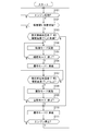
- FIG. 6 is a flowchart for explaining an example of use of the adsorption refrigeration system 2.
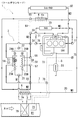
- FIG. 1 is a schematic diagram of an air conditioner 1 for a vehicle including an adsorption refrigeration system 2 according to an embodiment.
- A) of FIG. 1 is a figure explaining the flow of the refrigerant
- B) of FIG. 1 is a figure explaining the control apparatus 9 with which the air conditioner 1 is provided.
- FIG. 1A only a part of the adsorbent S accommodated in the container 51 of the adsorber 5 is shown.
- a cooler core 79 and a heater core 73 are provided on a flow path R1 of air Air (conditioned air) blown into the vehicle interior.
- air Air conditioned air
- the air Air passing through the cooler core 79 is cooled by heat exchange between the air Air passing through the cooler core 79 and the heat exchange medium M4 flowing through the cooler core 79.
- the heat exchange medium M4 heated by heat exchange with the air Air is returned from the cooler core 79 to the evaporator 3 and cooled by the evaporation core 3a included in the evaporator 3.
- the heat exchange medium M4 cooled by the evaporation core 3a is supplied again to the cooler core 79 and used for heat exchange with the air Air passing through the cooler core 79.
- the refrigerant M1 supplied from the condenser 4 side through the circulation path 20 is evaporated under reduced pressure, and the heat exchange medium M4 returned from the cooler core 79 side is evaporated by the heat of vaporization when the refrigerant M1 evaporates. It is configured to cool.
- two adsorbers 5 are provided in parallel on the downstream side of the evaporator 3.
- adsorbers 5A and 5B are simply denoted as adsorbers 5.
- a heat exchange core 52 is provided inside the container 51 filled with the adsorbent S.
- the heat exchange core 52 one of the cooling heat exchange medium M2 supplied from the circulation path 6 side and the heating heat exchange medium M3 supplied from the circulation path 7 side flows. ing.
- the adsorbent S in the container 51 is cooled / heated by heat exchange with the heat exchange media M2 and M3 flowing through the heat exchange core 52.
- the adsorbent S is an organic or inorganic adsorbent capable of adsorbing / desorbing the refrigerant M1 depending on the temperature, and cools the adsorbent S by heat exchange with the heat exchange media M2 and M3. / When heated, the adsorption / desorption of the refrigerant M1 with respect to the adsorbent S can be performed.
- adsorbent in the present specification is an organic polymer material or inorganic material having a characteristic of retaining (adsorbing) the refrigerant M1, and adsorbs the refrigerant M1 on the surface of this material. It means not only (general adsorbent) but also a material (so-called sorbent) that contains the refrigerant M1 inside the material.
- water is used as the refrigerant M1 that flows through the circulation path 20
- ethylene glycol is added to water as the heat exchange media M2, M3, and M4 that flow through the circulation paths 6 and 7, for example.
- a fluid mixed with the antifreeze of the system is used.
- the adsorber 5 when the adsorber 5 performs the adsorption of the refrigerant M1 onto the adsorbent S, the refrigerant M1 is sucked from the evaporator 3 side by the negative pressure generated by the adsorption of the refrigerant M1. Thus, the evaporation of the refrigerant M1 in the evaporator 3 is performed.
- the refrigerant M1 on the adsorbent S is saturated and the refrigerant M1 cannot be adsorbed, the refrigerant M1 cannot be sucked from the evaporator 3, and the evaporation of the refrigerant M1 in the evaporator 3 is stopped. End up.
- the adsorption refrigeration system 2 is provided with two adsorbers 5 (5A, 5B).
- the control device 9 includes a switching valve 21, 22 and an on-off valve 23 (23A, 23B) based on an output signal of a temperature sensor or a pressure sensor. 24 (24A, 24B) is controlled.
- the adsorber 5 that adsorbs the refrigerant M1 is alternately switched between the adsorber 5A and the adsorber 5B, and the evaporation of the refrigerant M1 in the evaporator 3 is continuously performed.
- a condenser 4 is provided on the downstream side of the adsorber 5.
- the gaseous refrigerant M1 desorbed from the adsorbent S is cooled by heat exchange with the heat exchange medium M2 in the core 4a of the condenser 4, and is condensed from the gaseous state to the liquid state. .
- the refrigerant M1 from the condenser 4 is stored downstream of the condenser 4, and a liquid tank (not shown) that separates the refrigerant M1 into gas and liquid, and an expansion valve that decompresses the refrigerant M1 (see FIG. (Not shown).
- the low-temperature and low-pressure refrigerant M1 decompressed by the expansion valve is supplied again to the evaporator 3 and evaporates in the evaporator 3.
- the refrigerant M ⁇ b> 1 is circulated in the circulation path 20 by using the adsorption and desorption of the refrigerant M ⁇ b> 1 to the adsorbent S, and along the circulation path 20. An adsorption refrigeration cycle is formed.
- the heat exchange medium flowing through the heat exchange core 52 of the adsorber 5 is switched between the heat exchange medium M2 for cooling and the heat exchange medium M3 for heating, and the adsorber
- the adsorbent S in 5 is cooled / heated.
- switching valves 55 and 56 are provided on the upstream side and the downstream side of the heat exchange core 52 of the adsorber 5 (5A, 5B).
- the connection destination of the heat exchange core 52 of each adsorber 5 (5A, 5B) is connected to the circulation path 6 through which the cooling heat exchange medium M2 flows and the heating heat exchange medium M3. Can be switched to and from the circulation path 7 through which.
- the control device 9 provided in the air conditioner 1 switches the connection destination of the heat exchange core 52 by operating the switching valves 55 and 56.
- the circulation path 6 of the cooling heat exchange medium M2 is provided with a heat exchanger 60 (sub-radiator), a condenser 4, and a pump (not shown).
- the heat exchange medium M2 cooled by heat exchange in the heat exchanger 60 is supplied to the adsorber 5 (5A, 5B) side through the circulation path 6.
- a CAC Charge Air Cooler
- the heat exchange medium M2 that has passed through the adsorber 5 (5A, 5B) is circulated to the heat exchanger 60 through the CAC, and is cooled in the heat exchanger 60.
- a bypass path 61 that bypasses the adsorber 5 (5A, 5B) is provided in the circulation path 6, a bypass path 61 that bypasses the adsorber 5 (5A, 5B) is provided.
- the heat exchange medium M2 cooled by the heat exchanger 60 is supplied to the CAC side through the bypass 61.
- the control device 9 operates the switching valves 65 and 66.
- the circulation path 7 of the heat exchange medium M3 for heating is a circulation path through which the medium for cooling the engine ENG flows.
- the circulation path 7 is a high-temperature heat exchange medium M3 heated by the exhaust heat of the engine ENG.
- the adsorbent S in the adsorber 5 (5A, 5B) is heated.
- an exhaust heat recovery device 81 is provided on the downstream side of the engine ENG.
- the exhaust heat recovery unit 81 is provided in the middle of the exhaust gas pipe 8 extending from the engine ENG, and includes a heat exchange medium M3 flowing through the circulation path 7, a high-temperature exhaust gas exhausted from the exhaust gas pipe 8.
- the heat exchange medium M3 can be heated by this heat exchange.
- a heater core 73 is provided on the downstream side of the exhaust heat recovery unit 81, and the heater core 73 is installed on the downstream side of the cooler core 79 in the flow path R1. Therefore, when the air Air flowing through the flow path R1 passes through the heater core 73, it is heated by heat exchange with the heat exchange medium M3 heated by the exhaust heat recovery device 81.
- the circulation path 7 is provided with a flow path 71 that connects the upstream side and the downstream side of the engine ENG.
- the flow path 71 is provided with a heat exchanger 70 (radiator) and a pump (not shown). ing.
- the control device 9 operates the switching valves 77 and 78 so that the heat exchange medium M3 is passed through the flow path 71. Only the side can be passed.
- a bypass path 72 that bypasses the exhaust heat recovery device 81 and the heater core 73 is provided.
- the flow path is switched by the switching valves 75 and 76, and the bypass path 72.
- a heat exchange medium M3 flows therethrough. Then, the heat exchange medium M3 that has passed through the engine ENG is directly supplied to the adsorber 5 side.
- a bypass path 59 that bypasses the adsorber 5B is provided between the switching valves 55 and 56 described above. Then, when the control device 9 operates the switching valves 57 and 58 so that the heat exchange medium M3 flows through the bypass passage 59, the heat exchange medium M3 does not pass through the adsorber 5B, but the engine ENG side. To come to reach.
- the control device 9 passes through the heat exchange medium M ⁇ b> 3 passing through the circulation path 7 and the heat exchange medium M ⁇ b> 3 supplied to the heat exchange core 52 of each adsorber 5 (5 ⁇ / b> A, 5 ⁇ / b> B) and the circulation path 6. It switches between the heat exchange medium M2 which flows. Thereby, the adsorption / desorption of the refrigerant M1 in each adsorber 5 (5A, 5B) is controlled.
- the following modes are prepared in addition to the above-described (1) normal cooling mode.
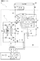
- FIG. 2 is a diagram for explaining the flow of the refrigerant M1 and the heat exchange media M2 and M3 when the adsorption refrigeration system 2 is used in the cool-down mode.
- FIG. 3 is a diagram illustrating the flow of the refrigerant M1 and the heat exchange media M2 and M3 when the adsorption refrigeration system 2 is used in the warm-up mode.
- FIG. 4 is a diagram illustrating the flow of the refrigerant M1 and the heat exchange media M2 and M3 when the adsorption refrigeration system 2 is used in the transition mode 1.
- FIG. 2 is a diagram for explaining the flow of the refrigerant M1 and the heat exchange media M2 and M3 when the adsorption refrigeration system 2 is used in the cool-down mode.
- FIG. 3 is a diagram illustrating the flow of the refrigerant M1 and the heat exchange media M2 and M3 when the adsorption refrigeration system 2 is used in the warm-up mode.
- FIG. 4 is a diagram illustrating the flow
- FIG. 5 is a diagram illustrating the flow of the refrigerant M1 and the heat exchange media M2 and M3 when the adsorption refrigeration system 2 is used in the heat storage mode.
- FIG. 6 is a diagram illustrating the flow of the refrigerant M1 and the heat exchange media M2 and M3 when the adsorption refrigeration system 2 is used in the transition mode 2.
- Cool-down mode The cool-down mode is performed at the start of cooling operation in summer. Immediately after the start of cooling operation in summer, the passenger compartment is often hot. Therefore, when the temperature Tr in the vehicle interior immediately after the start of the cooling operation is higher than the threshold temperature Th_r for determining whether or not to perform the cool-down mode, the vehicle interior is cooled in order to quickly cool the vehicle interior to an appropriate temperature. Down mode is implemented.
- the adsorption of the refrigerant M1 to the adsorbent S is simultaneously performed by the adsorbers 5A and 5B.
- the control device 9 operates the switching valves 55, 56, 57, and 58, and the circulation path 6 through which the heat exchange medium M2 for cooling flows through the heat exchange core 52 of the adsorbers 5A and 5B. Connect to. Thereby, the adsorbent S in the adsorbers 5A and 5B is cooled by the heat exchange medium M2 for cooling.
- the control device 9 operates the switching valve 21 and the on-off valve 23 (23A and 23B), and the adsorbers 5A and 5B. Communicate with the evaporator 3 side.
- the refrigerant M1 is adsorbed to the adsorbent S in parallel, and the refrigerant M1 is sucked from the evaporator 3 side by the negative pressure generated by the adsorption. Since this suction force is stronger than when only one of the adsorbers 5A and 5B adsorbs the refrigerant M1 to the adsorbent S, the evaporation amount of the refrigerant M1 in the evaporator 3 is only the one of the adsorbers 5A and 5B. Therefore, the amount of the refrigerant M1 is larger than that when the refrigerant M1 is adsorbed to the adsorbent S.
- the air Air passing through the evaporator 3 is cooled to a lower temperature.
- the temperature of the cooled (cooled) air supplied to the passenger compartment is higher than that in the case where the refrigerant M1 is adsorbed on the adsorbent S by only one adsorber 5 (adsorber 5A or adsorber 5B).
- the temperature of the passenger compartment is lowered to a suitable temperature more quickly.
- Warm-up mode is performed when the engine is started in a low temperature environment. For example, immediately after the engine is started in winter, the engine ENG is often at a low temperature. Therefore, when the temperature T_M3 of the cooling water (heat exchange medium M3) of the engine ENG immediately after the engine start is lower than the threshold temperature Th_w for determining whether or not the warm-up mode is to be performed, the engine ENG is promptly turned on. In order to warm up, the warm-up mode is performed.
- the heat exchange medium M3 is heated by the heat of adsorption due to the adsorption of the refrigerant M1 on the adsorbent S, and the engine ENG is warmed (warmed up) by the heated heat exchange medium M3.
- the adsorption of the refrigerant M1 to the adsorbent S is performed in parallel by the adsorbers 5A and 5B.
- control device 9 operates the switching valve 21 and the on-off valve 23 (23A, 23B) to make the adsorbers 5A, 5B communicate with the evaporator 3 side.
- the control device 9 operates the switching valve 21 and the on-off valve 23 (23A, 23B) to make the adsorbers 5A, 5B communicate with the evaporator 3 side.
- the control apparatus 9 operates the switching valves 55, 56, 57, 58, and the heat exchange core of adsorption machine 5A, 5B. 52 is connected to the circulation path 7 through which the heat exchange medium M3 flows. As a result, when the heat exchange medium M3 passes through the heat exchange core 52, it is heated by heat exchange with the adsorbent S that has generated heat by adsorption heat.
- the heat exchange medium M3 heated by the adsorbers 5A and 5B flows through the engine ENG located at the rear stage of the adsorber 5 in the circulation path 7. At this time, the engine ENG is moved by the heat exchange medium M3. It will be warmed up and warmed up.
- the control device 9 operates the switching valves 75 and 76 so that the heat exchange medium M3 does not pass through the exhaust heat recovery device 81 and the heater core 73 but passes through the bypass passage 72.
- the engine ENG and the adsorber 5 are circulated only. This is because the engine ENG is quickly warmed up. For example, immediately after the start of the engine ENG in winter, the temperature of the exhaust gas flowing through the exhaust gas pipe 8 is often low, so the amount of heat of the heat exchange medium M3 heated by heat exchange in the adsorbers 5A and 5B is The engine ENG is used only for warming up.
- the control device 9 checks whether or not the temperature Tg of the exhaust gas flowing through the exhaust gas pipe 8 is equal to or higher than a threshold temperature Th1 at which the heat exchange medium M3 can be heated by heat exchange with the exhaust gas. To do. Then, the control device 9 sets the switching valves 75 and 76 so that the heat exchange medium M3 flows through the exhaust heat recovery device 81 and the heater core 73 when the temperature Tg of the exhaust gas becomes equal to or higher than the threshold temperature Th1. Manipulate.
- the heat exchange medium M3 is heated by heat exchange with the exhaust gas in addition to heat exchange with the exhaust heat of the engine, so that the heat exchange medium M3 flowing downstream from the exhaust heat recovery unit 81 The temperature of this will rise quickly.
- the heat exchange medium M3 heated by the heat exchange with the exhaust gas passes through the heater core 73, the heat exchange medium M3 exchanges heat with the air Air passing through the heater core 73. Air Air supplied to the room is heated.
- the control device 9 operates the switching valves 65 and 66 so that the heat exchange medium M2 circulates only between the heat exchanger 60, the condenser 4, and the CAC (Charge Air Cooler).
- the temperature T_M3 of the heat exchange medium M3 at the engine ENG outlet increases.
- the temperature T_M3 of the heat exchange medium M3 at the outlet of the engine ENG becomes higher than the temperature Tx of the heat exchange medium M3 at the outlet of the adsorber 5, the heat exchange in the adsorbers 5A and 5B.
- the heating of the heat exchange medium M3 is terminated.
- the operation mode of the adsorption refrigeration system 2 is switched from the warm-up mode to the transition mode 1.
- Transition mode 1 is suitable for the temperature of the heat exchange medium M3 to desorb the refrigerant M1 in the adsorbers 5A and 5B after the heating of the heat exchange medium M3 by heat exchange in the adsorbers 5A and 5B is completed. It is carried out to wait until the temperature reaches the threshold temperature (threshold temperature Th_r).
- the control device 9 controls the switching valves 55, 56, 57, and 58 so that the heat exchange medium M3 bypasses the adsorber 5 without passing through the adsorber 5 (5A, 5B).
- the bypass passage 59 is made to flow.
- the adsorption type The operation mode of the refrigeration system 2 is switched from the transition mode 1 to the heat storage mode.
- Heat storage mode is implemented to enable the above-described warm-up mode.
- the heat storage mode is performed in order to desorb the refrigerant M1 from the adsorbent S when the temperature of the heat exchange medium M3 is high while the engine ENG is activated.
- the heat storage mode is performed following the transition mode 1 after the operation mode of the adsorption refrigeration system 2 is switched from the warm-up mode to the transition mode 1.
- the desorption of the refrigerant M1 from the adsorbent S is performed in parallel by the adsorbers 5A and 5B.
- the control device 9 controls the switching valves 55, 56, By operating 57 and 58, the heat exchange core 52 of the adsorbers 5A and 5B is connected to the circulation path 7 of the heat exchange medium M3.
- the adsorbent S in the adsorbers 5A and 5B is heated by heat exchange with the heat exchange medium M3 passing through the heat exchange core 52.
- the control device 9 operates the switching valve 21 and the on-off valve 23 (23A and 23B), and the adsorbers 5A and 5B, the evaporator 3 side, And the switching valve 22 and the on-off valve 24 (24A, 24B) are operated to connect the adsorbers 5A, 5B and the capacitor 4 side.
- the desorption of the refrigerant M1 from the adsorbent S is performed in parallel, and the gaseous refrigerant M1 desorbed from the adsorbent S with the pressure generated by the desorption is transferred to the condenser 4 side. Will be discharged. And the refrigerant
- the heat exchange medium M3 supplied to the adsorbers 5A and 5B is heated by heat exchange with the exhaust heat recovery unit 81, the heat exchange medium M3 is heated only by the exhaust heat of the engine ENG. Compared to, the adsorbent S can be heated to a higher temperature. Therefore, the adsorption refrigeration system 2 can be maximized. In particular, in the summer when heat dissipation from the engine ENG becomes severe, the amount of heat recovered by the exhaust heat recovery device 81 is consumed for heat exchange with the heat exchange medium M3. Therefore, it is possible to suitably prevent an increase in the size of the radiator for dissipating the generated heat.
- the heat exchange medium M2 includes the heat exchanger 60, the condenser 4,
- the control device 9 operates the switching valves 65 and 66 so as to circulate only between the CAC (Charge Air Cooler).
- the controller 9 then adsorbs the adsorber when the temperature Tx of the heat exchange medium M3 at the outlet of the adsorber 5 becomes higher than the threshold temperature Th_f for determining the end of desorption of the refrigerant M1 from the adsorbent S.
- the desorption of the refrigerant M1 from the adsorbent S in 5A and 5B is terminated.
- the operation mode of the adsorption refrigeration system 2 is switched from the heat storage mode to the transition mode 2.
- Transition mode 2 is a mode that is implemented after the end of the heat storage mode. In this mode, the adsorbers 5A and 5B are continuously held in a state in which the warm-up mode can be quickly started.
- the control device 9 operates the switching valve 22 and the on-off valve 24 (24A, 24B) to block communication between the adsorbers 5A, 5B and the capacitor 4 side. Thereby, in the adsorbers 5A and 5B in the state in which the on-off valves 23 (23A and 23B) and 24 (24A and 24B) are closed, the adsorbent S in the container 51 is held in the desorbed state. .
- the warm-up mode described above is immediately started.
- the refrigerant M1 is adsorbed onto the adsorbent S in the adsorbers 5A and 5B, and the engine ENG can be quickly warmed up.
- FIG. 7 is a flowchart for explaining an example of use of the adsorption refrigeration system 2.
- step S102 the control device 9 confirms whether or not the adsorbent S in the adsorber 5 is in a desorption state in which the refrigerant M1 is not adsorbed. This is for confirming whether or not the warm-up mode can be performed.
- whether or not the adsorbent S is in the desorbed state is confirmed based on the use history of the adsorption refrigeration system 2 stored in a storage unit (not shown), the pressure and temperature in the adsorber 5, and the like.
- the control device 9 sets the temperature of the cooling water (heat exchange medium M3) of the engine ENG. Based on this, it is confirmed whether or not it is necessary to implement the warm-up mode.
- step S103 the control device 9 determines whether or not the temperature T_M3 of the cooling water (heat exchange medium M3) of the engine ENG is lower than a threshold temperature Th_w for determining whether or not to implement the warm-up mode. To check. When the temperature is lower than the threshold temperature Th_w, the control device 9 determines that the warm-up mode is performed.
- the threshold temperature Th_w is determined based on, for example, an average temperature of the heat exchange medium M3 immediately after the start of the engine ENG in winter. When the temperature T_M3 of the heat exchange medium M3 is lower than the threshold temperature Th_w, it is determined that the engine needs to be warmed up immediately after the engine ENG is started in winter, for example.
- the adsorption of the refrigerant M1 to the adsorbent S is performed in parallel in both adsorbers 5 (5A, 5B).
- the heat exchange medium M3 flowing through the heat exchange core 52 of the adsorber 5 (5A, 5B) is heated by heat exchange with the adsorbent S and then flows through the engine ENG.
- the engine ENG is warmed up by the heat exchange medium M3.
- the control device 9 Determines the end of the warm-up mode (step S105, Yes).
- step S106 the control device 9 switches the operation mode of the adsorption refrigeration system 2 from the warm-up mode to the transition mode 1. Specifically, the control device 9 operates the switching valves 55, 56, 57, and 58 to stop the supply of the heat exchange medium M3 to the adsorber 5.
- step S107 it is confirmed whether or not the heat storage mode can be performed. This is because since the refrigerant M1 is adsorbed on the adsorbent S at the end of the warm-up mode, it is necessary to implement a heat storage mode in which the refrigerant M1 is desorbed from the adsorbent S.
- the control device 9 waits for the temperature T_M3 of the heat exchange medium M3 to be equal to or higher than the threshold temperature Th_r at which the refrigerant M1 can be desorbed from the adsorbent S (Step S107, Yes). ), The heat storage mode is performed (step S108).
- step S107 the confirmation as to whether or not the heat storage mode in step S107 can be performed is performed even when the control device 9 determines in step S102 that the adsorbent S is not in the desorbed state (step S102). , No) Implemented.
- the control device 9 operates the switching valves 55, 56, 57, and 58 to start supplying the heat exchange medium M3 for heating to the adsorber 5, and also opens and closes the switching valve 22.
- the valve 24 (24A, 24B) is operated to make the adsorber 5 (5A, 5B) and the condenser 4 side communicate with each other. Therefore, in the adsorber 5 (5A, 5B), the adsorbent S is heated by heat exchange with the heat exchange medium M3 for heating, and the refrigerant M1 from the adsorbent S of both adsorbers 5 (5A, 5B). The desorption will be performed in parallel.
- the adsorber 5 (5A, 5B) is held in a state where communication is cut off on both the evaporator 3 side and the capacitor 4 side. Thereby, the adsorber 5 (5A, 5B) adsorbs the refrigerant M1 not only while the engine is being driven but also after the engine is stopped (Yes in step S111) when communication with the evaporator 3 side is resumed. It will continue to be held in a state where it can start quickly.
- step S101, Yes When the stopped engine is started (step S101, Yes), the adsorber 5 (5A, 5B) is held in a desorbed state in which the adsorption of the refrigerant M1 can be started promptly even after the engine is stopped ( Step S102, Yes).
- the temperature T_M3 of the heat exchange medium M3 at the time of starting the engine is lower than the threshold temperature Th_w for determining whether or not the warm-up mode is necessary (Yes in step S103)
- the warm-up mode is immediately started (Ste S104).
- the transition mode 2 is performed (step S110).
- a circulation path 7 (first circulation path) through which the heat exchange medium M3 for heating circulates;
- a circulation path 6 (second circulation path) through which the heat exchange medium M2 for cooling circulates;
- the heat exchange medium supplied to each of the adsorbers 5 (5A, 5B) is switched between the heat exchange medium M3 that circulates in the circulation path 7 and the heat exchange medium that circulates in the circulation path 6, and the adsorber 5 (5A) 5B), an adsorption refrigeration system 2 having a control device 9 (control means) for controlling adsorption / desorption of the refrigerant M1 in each of The control device 9
- the temperature T_M3 of the heat exchange medium M3 circulating in the circulation path 7 is lower than a predetermined threshold temperature Th_w, the heat exchange medium M3 circulating in the circulation path 7 is
- the adsorption of the refrigerant M1 is performed in parallel in each of the adsorbers 5 (5A, 5B), and the heat exchange medium M3 circulating in the circulation path 7 is heated by the adsorption heat of the adsorbent S that adsorbs the refrigerant M1. It was set as the structure to do.
- the heat exchange medium M3 that circulates in the circulation path 7 is heated by adsorption heat when passing through the adsorber 5 (5A, 5B), so that the heat exchange medium M3 that circulates in the circulation path 7 The temperature will rise.
- coolant M1 is implemented in parallel with each of adsorption machine 5 (5A, 5B)
- the heat exchange medium M3 of the circulation path 7 distributed to each adsorption machine 5 (5A, 5B) is adsorption
- the heating efficiency of the heat exchange medium M3 by adsorption heat is improved, the temperature of the heat exchange medium M3 passing through the adsorber 5 (5A, 5B) can be quickly raised. Therefore, since the other equipment can be warmed up by the heated heat exchange medium M3 circulating through the circulation path 7, for example, the other equipment can be quickly warmed up immediately after startup in the winter season.
- the operation frequency of the adsorption refrigeration system 2 can be increased at times other than the cooling operation.
- the heat exchange medium M3 circulating in the circulation path 7 is a heat exchange medium for cooling the engine ENG.
- the heat exchange medium M3 for cooling the engine ENG can be warmed, and the heated heat exchange medium M3 passes through the engine ENG. Warm-up is promoted.
- the time required for warming up the engine ENG can be shortened, and particularly in the winter season when the temperature of the heat exchange medium M3 is low, the time required for warming up the engine ENG can be shortened.
- At least one or more devices for performing heat exchange with the heat exchange medium M3 circulating in the circulation path 7 are provided, and at least one of these devices.
- a bypass path 72 (first bypass path) that bypasses the above is provided, While the heat exchanger medium M3 circulating through the circulation path 7 is heated with adsorption heat, the control device 9 causes the heat exchange medium M3 to flow through the bypass path 72 and heat with the heat exchange medium M3. It was set as the structure which bypasses at least 1 or more of the apparatus to exchange.
- the heat exchange medium M3 heated by the adsorption heat exchanges heat with equipment other than the engine ENG, and the temperature of the heat exchange medium M3 decreases. Can be prevented. Therefore, it is possible to quickly warm up only the engine ENG.
- the circulation path 7 is provided with a bypass path 59 (second bypass path) that bypasses the adsorber 5 (5A, 5B).
- the control device 9 When the heat exchange medium M3 circulating in the circulation path 7 is heated with adsorption heat, the temperature Tx of the heat exchange medium M3 after passing through the engine ENG is heated by the adsorber 5 (5A, 5B). When the temperature becomes higher than the temperature T_M3 of the exchange medium M3, the heat exchange medium M3 is caused to flow through the bypass path 59 to bypass the adsorber 5 (5A, 5B).
- one heat exchange core 52 (flow passage) through which the heat exchange medium flows is provided so as to be able to exchange heat with the adsorbent S. did.
- the heat exchange medium supplied to each of the adsorbers 5 includes the heat exchange medium M3 for heating circulating in the circulation path 7 and the heat for cooling circulating in the circulation path 6. Since the heat exchange medium flowing through the heat exchange core 52 of the adsorber 5 (5A, 5B) is switched every time the exchange medium M2 is switched, the adsorbent S can be heated / cooled quickly.
- the heating flow path The supply of the heat exchange medium for heating to the passage is stopped, and the supply of the heat exchange medium for cooling to the cooling flow path is started. Thereby, the heat of the heat exchange medium remaining in the heating flow path inhibits cooling of the adsorbent by the cooling heat exchange medium flowing through the cooling flow path.
- the heat exchange remaining in the cooling flow path The heat of the medium inhibits the heating of the adsorbent by the heating heat exchange medium that flows through the heating flow path.
- the adsorber 5 (5A, 5B) according to the present invention having only one heat exchange core 52 (flow channel) through which the heat exchange medium flows has a heating / cooling speed of the adsorbent S.
- the refrigerant for the adsorbent is more than the adsorber having both the heating flow path through which the heat exchange medium M for heating flows and the cooling flow path through which the heat exchange medium for cooling flows. The adsorption / desorption can be switched promptly.
- the condenser 4 that cools and liquefies the refrigerant M1
- the evaporator 3 that vaporizes the liquefied refrigerant M1 under reduced pressure
- the adsorption / desorption of the refrigerant M1 depending on the temperature.
- a plurality of adsorbers 5 (5A, 5B) filled with possible adsorbents S, and the negative produced by adsorption of the refrigerant M1 on the adsorbents S in the adsorbers 5 (5A, 5B).
- the vehicle is equipped with an adsorption refrigeration system 2 configured to evaporate the refrigerant M1 in the evaporator 3 by using pressure, and the evaporator 3 is used for cooling the air supplied to the vehicle interior.
- the air conditioner 1 was used.
- the compressor is not required for the air_conditioning
- the electric energy consumed for the drive of a compressor can be reduced. Therefore, when the vehicle air conditioner 1 is a vehicle (for example, an electric vehicle) equipped with a battery-powered motor, battery consumption can be suppressed, so that the vehicle travels with a single charge. The possible distance can be improved.
- a control device 9 control means for controlling adsorption / desorption of the refrigerant M1 in each of 5A, 5B), and a control method of the adsorption refrigeration system 2 comprising:
- the control device 9 is When the temperature T_M3 of the heat exchange medium M3 circulating in the circulation path 7 is high, which is equal to or higher than a predetermined threshold temperature Th_
- a heat storage step of performing the desorption of the refrigerant M1 in parallel in each of the adsorbers 5 (A, 5B)
- a transition step for holding the adsorbent S in a degassed state When the temperature T_M3 of the heat exchange medium M3 circulating in the circulation path 7 is lower than a predetermined threshold temperature Th_w, the heat exchange medium M3 circulating in the circulation path 7 is supplied to each of the adsorbers 5 (5A, 5B).
- the adsorption of the refrigerant M1 is performed in parallel in each of the adsorbers 5 (5A, 5B), and the heat exchange medium M3 circulating in the circulation path 7 is heated by the adsorption heat of the adsorbent S that adsorbs the refrigerant M1. Then, a warming-up step of warming up the engine ENG with the heated heat exchange medium M3, It was set as the control method of the adsorption
- the heat exchange medium M3 for cooling the engine ENG can be warmed, and the heated heat exchange medium M3 passes through the engine ENG. Warm-up is promoted.
- the time required for warming up the engine ENG can be shortened, and particularly in the winter season when the temperature of the heat exchange medium M3 is low, the time required for warming up the engine ENG can be shortened.
- the heat exchange mode can always be implemented by desorbing the refrigerant M1 with each adsorber 5 (5A, 5B) by the heat exchange medium M3 heated by the exhaust heat of the engine ENG. Can continue to hold.
- the adsorption refrigeration system 2 includes two adsorbers 5 (5A, 5B) is illustrated, but the number of the adsorbers 5 included in the adsorption refrigeration system 2 is limited to two. It is not necessary to provide at least two.
- the heat exchange medium M3 warmed by the adsorption heat is used for warming up the engine ENG is exemplified, the heat exchange medium M3 may be used for warming up other equipment that needs warming up. Further, the heat quantity of the heat exchange medium M3 heated by the adsorption heat may be used for heating the conditioned air in the heater core 73 of the air conditioner 1.
- bypass path 72 bypasses the heater core 73 and the exhaust heat recovery unit 81
- the bypass path 72 connects one of the heater core 73 and the exhaust heat recovery unit 81. What is necessary is just to be provided so that it may detour.
- Air Conditioner 2 Adsorption Refrigeration System 3
- Evaporator 4 condenser (condenser) 5A, 5B
- Adsorber 6 7 Circulation path 8
- Exhaust gas pipe 9 Control device 20 Circulation path 21, 22 Switching valve 23 (23A, 23B), 24 (24A, 24B) On-off valve 51
- Container 52 Heat exchange core 55 ⁇ 58
- Switching valve 59 Bypass path 60 Heat exchanger (sub-radiator) 61 Bypass path 65, 66
- Switching valve 70 Heat exchanger (radiator) 71 Flow path 72 Bypass path 73 Heater core 75 to 78
- Switching valve 79 Cooler core 81
- R1 Flow path S Adsorbent
Landscapes
- Engineering & Computer Science (AREA)
- Physics & Mathematics (AREA)
- Mechanical Engineering (AREA)
- Thermal Sciences (AREA)
- General Engineering & Computer Science (AREA)
- Chemical & Material Sciences (AREA)
- Combustion & Propulsion (AREA)
- Air-Conditioning For Vehicles (AREA)
- Sorption Type Refrigeration Machines (AREA)
Abstract
温度に応じて冷媒(M1)の吸着/脱着が可能な吸着材(S)が充填された複数の吸着器(5A、5B)と、吸着器(5A、5B)の各々に供給する熱交換媒体を、循環路(7)を循環する熱交換媒体(M3)と、循環路(6)を循環する熱交換媒体(M2)の間で切り換えて、吸着器(5A、5B)の各々での冷媒(M1)の吸着/脱着を制御する制御装置(9)と、を有する吸着式冷凍システム(2)において、制御装置(9)は、循環路(7)を循環する熱交換媒体(M3)の温度が、所定温度未満である場合に、循環路(7)を循環する熱交換媒体(M3)を吸着器(5A、5B)の各々に供給すると共に、吸着器(5A、5B)の各々で冷媒(M1)の吸着を並行して実施して、循環路(7)を循環する熱交換媒体(M3)を、冷媒(M1)を吸着した吸着材(S)の吸着熱で加熱する。
Description
本発明は、吸着式冷凍システム、および車両用の空調装置に関する。
特許文献1には、車両のラジエータから排熱される熱量を利用して駆動する吸着式冷凍システムが開示されている。
この吸着式冷凍システムでは、車両のラジエータから排熱されていたエンジンの熱量を、温度に応じて冷媒の脱着/吸着を行う吸着材の加熱に利用している。
そして、この吸着式冷凍システムでは、吸着材への冷媒の吸着を利用して、エバポレータでの冷媒の蒸発を行っている。
この吸着式冷凍システムを備える車両用の空調装置では、エバポレータとクーラコアとの間を循環する熱交換媒体を、エバポレータでの冷媒の蒸発を利用して冷却する。そして、冷却された熱交換媒体とクーラコアを通過する空気との間での熱交換により、車室内に供給される空気を冷却している。
この吸着式冷凍システムを備える車両用の空調装置では、エバポレータとクーラコアとの間を循環する熱交換媒体を、エバポレータでの冷媒の蒸発を利用して冷却する。そして、冷却された熱交換媒体とクーラコアを通過する空気との間での熱交換により、車室内に供給される空気を冷却している。
しかし、吸着式冷凍システムは、車両用の空調装置の冷房運転時での使用を前提としており、例えば冬季のように冷房運転の機会がないときには、稼動されずに停止している。
そのため、冷房運転時以外での吸着式冷凍システムの稼働頻度を高めることが求められている。
本発明は、
温度に応じて冷媒の吸着/脱着が可能な吸着材が充填された複数の吸着器と、
加熱用の熱交換媒体が循環する第1循環路と、
冷却用の熱交換媒体が循環する第2循環路と、
前記吸着器の各々に供給する熱交換媒体を、前記第1循環路を循環する熱交換媒体と、前記第2循環路を循環する熱交換媒体の間で切り換えて、前記吸着器の各々での前記冷媒の吸着/脱着を制御する制御手段と、を有する吸着式冷凍システムにおいて、
前記制御手段は、
前記第1循環路を循環する熱交換媒体の温度が、所定温度未満である場合に、前記第1循環路を循環する熱交換媒体を前記吸着器の各々に供給すると共に、前記吸着器の各々で前記冷媒の吸着を並行して実施して、前記第1循環路を循環する熱交換媒体を、吸着熱で加熱することを特徴とする吸着式冷凍システム。
温度に応じて冷媒の吸着/脱着が可能な吸着材が充填された複数の吸着器と、
加熱用の熱交換媒体が循環する第1循環路と、
冷却用の熱交換媒体が循環する第2循環路と、
前記吸着器の各々に供給する熱交換媒体を、前記第1循環路を循環する熱交換媒体と、前記第2循環路を循環する熱交換媒体の間で切り換えて、前記吸着器の各々での前記冷媒の吸着/脱着を制御する制御手段と、を有する吸着式冷凍システムにおいて、
前記制御手段は、
前記第1循環路を循環する熱交換媒体の温度が、所定温度未満である場合に、前記第1循環路を循環する熱交換媒体を前記吸着器の各々に供給すると共に、前記吸着器の各々で前記冷媒の吸着を並行して実施して、前記第1循環路を循環する熱交換媒体を、吸着熱で加熱することを特徴とする吸着式冷凍システム。
本発明によれば、冷房運転時以外での吸着式冷凍システムの稼働頻度を高めることができる。
以下、本発明の実施の形態を説明する。
図1は、実施の形態にかかる吸着式冷凍システム2を備える車両用の空調装置1の概略図である。図1の(a)は、吸着式冷凍システム2を通常冷房モードで使用している場合の冷媒M1や熱交換媒体M2、M3の流れを説明する図である。図1の(b)は、空調装置1が備える制御装置9を説明する図である。
なお、図1の(a)では、吸着器5の容器51に収容された吸着材Sの一部のみを示している。
図1は、実施の形態にかかる吸着式冷凍システム2を備える車両用の空調装置1の概略図である。図1の(a)は、吸着式冷凍システム2を通常冷房モードで使用している場合の冷媒M1や熱交換媒体M2、M3の流れを説明する図である。図1の(b)は、空調装置1が備える制御装置9を説明する図である。
なお、図1の(a)では、吸着器5の容器51に収容された吸着材Sの一部のみを示している。
車両用の空調装置1では、車室内に吹き出す空気Air(空調空気)の流路R1上にクーラコア79とヒータコア73とが設けられている。この空調装置1では、クーラコア79を通過する空気Airと、クーラコア79内を通流する熱交換媒体M4との間での熱交換により、クーラコア79を通過する空気Airを冷却している。
そして、空気Airとの熱交換により暖められた熱交換媒体M4は、クーラコア79からエバポレータ3に戻されて、エバポレータ3が備える蒸発コア3aで冷却される。
蒸発コア3aで冷却された熱交換媒体M4は、クーラコア79に再び供給されて、クーラコア79を通過する空気Airとの間での熱交換に利用される。
蒸発コア3aで冷却された熱交換媒体M4は、クーラコア79に再び供給されて、クーラコア79を通過する空気Airとの間での熱交換に利用される。
エバポレータ3では、循環路20を介してコンデンサ4側から供給された冷媒M1を減圧下で蒸発させて、冷媒M1が蒸発する際の気化熱で、クーラコア79側から戻された熱交換媒体M4を冷却するように構成されている。
冷媒M1の循環路20では、エバポレータ3の下流側に、2つの吸着器5(5A、5B)が並列に設けられている。
なお、以下の説明においては、吸着器5A、5Bを特に区別しない場合には、単純に吸着器5と標記する。
なお、以下の説明においては、吸着器5A、5Bを特に区別しない場合には、単純に吸着器5と標記する。
吸着器5では、吸着材Sが充填された容器51の内部に、熱交換コア52が設けられている。
この熱交換コア52は、循環路6側から供給された冷却用の熱交換媒体M2と、循環路7側から供給された加熱用の熱交換媒体M3のうちの一方が通流するようになっている。
容器51内の吸着材Sは、熱交換コア52を通流する熱交換媒体M2、M3との熱交換により、冷却/加熱される。
この熱交換コア52は、循環路6側から供給された冷却用の熱交換媒体M2と、循環路7側から供給された加熱用の熱交換媒体M3のうちの一方が通流するようになっている。
容器51内の吸着材Sは、熱交換コア52を通流する熱交換媒体M2、M3との熱交換により、冷却/加熱される。
吸着材Sは、温度に応じて冷媒M1の吸着/脱着が可能な有機系、または無機系の吸着材であり、熱交換媒体M2、M3との間での熱交換により、吸着材Sを冷却/加熱すると、吸着材Sに対する冷媒M1の吸着/脱着が行えるようになっている。
ここで、本明細書における用語「吸着材」は、冷媒M1を保持(吸着)する特性を有する有機系の高分子材料や無機材料であって、この材料の表面に、冷媒M1を吸着させるもの(一般的な吸着材)だけではなく、材料の内部に冷媒M1を収容するもの(いわゆる収着材)の両方を意味している。
また、実施の形態では、循環路20を通流する冷媒M1として、例えば水を用いており、循環路6、7を通流する熱交換媒体M2、M3、M4として、例えば、水にエチレングリコール系の不凍液を混合した流体を用いている。
この吸着器5を備える吸着式冷凍システム2では、吸着器5において吸着材Sへの冷媒M1の吸着を実施すると、冷媒M1の吸着で生じた負圧により、エバポレータ3側から冷媒M1が吸引されて、エバポレータ3での冷媒M1の蒸発が行われるようになっている。
ここで、吸着材Sへの冷媒M1の吸着量が飽和して、冷媒M1の吸着ができなくなると、エバポレータ3側から冷媒M1を吸引できなくなって、エバポレータ3での冷媒M1の蒸発が停止してしまう。
ここで、吸着材Sへの冷媒M1の吸着量が飽和して、冷媒M1の吸着ができなくなると、エバポレータ3側から冷媒M1を吸引できなくなって、エバポレータ3での冷媒M1の蒸発が停止してしまう。
そのため、吸着式冷凍システム2には、2つの吸着器5(5A、5B)が設けられている。そして、空調装置1の冷房運転時(通常冷房モード)には、一方の吸着器5Aで冷媒M1の吸着を行っている間、他方の吸着器5Bで吸着材Sからの冷媒M1の脱着が行われるようになっている。
吸着式冷凍システム2では、制御装置9(図1の(b)参照)が、温度センサや圧力センサの出力信号などに基づいて、切替弁21、22と、開閉弁23(23A、23B)、24(24A、24B)を制御する。これにより、冷媒M1の吸着を行う吸着器5が、吸着器5Aと吸着器5Bの間で交互に切り替えられて、エバポレータ3での冷媒M1の蒸発が連続して行われるようになっている。
吸着式冷凍システム2では、制御装置9(図1の(b)参照)が、温度センサや圧力センサの出力信号などに基づいて、切替弁21、22と、開閉弁23(23A、23B)、24(24A、24B)を制御する。これにより、冷媒M1の吸着を行う吸着器5が、吸着器5Aと吸着器5Bの間で交互に切り替えられて、エバポレータ3での冷媒M1の蒸発が連続して行われるようになっている。
冷媒M1の循環路20では、吸着器5の下流側にコンデンサ4が設けられている。
コンデンサ4では、吸着材Sから脱着した気体状態の冷媒M1が、このコンデンサ4のコア4aにおける熱交換媒体M2との熱交換により冷却されて、気体状態から液体状態に凝縮するようになっている。
コンデンサ4では、吸着材Sから脱着した気体状態の冷媒M1が、このコンデンサ4のコア4aにおける熱交換媒体M2との熱交換により冷却されて、気体状態から液体状態に凝縮するようになっている。
さらに、循環路20では、コンデンサ4の下流側に、コンデンサ4からの冷媒M1を溜めると共に、冷媒M1を気液に分離するリキッドタンク(図示せず)と、冷媒M1を減圧する膨張弁(図示せず)と、が設けられている。
膨張弁で減圧された低温低圧の冷媒M1は、前記したエバポレータ3に再び供給されて、エバポレータ3内で蒸発する。
このように、吸着式冷凍システム2では、冷媒M1が、吸着材Sへの冷媒M1の吸着と脱着を利用して、循環路20内を循環するようになっており、循環路20に沿って吸着式冷凍サイクルが形成されている。
膨張弁で減圧された低温低圧の冷媒M1は、前記したエバポレータ3に再び供給されて、エバポレータ3内で蒸発する。
このように、吸着式冷凍システム2では、冷媒M1が、吸着材Sへの冷媒M1の吸着と脱着を利用して、循環路20内を循環するようになっており、循環路20に沿って吸着式冷凍サイクルが形成されている。
吸着式冷凍システム2では、吸着器5の熱交換コア52を通流する熱交換媒体が、冷却用の熱交換媒体M2と、加熱用の熱交換媒体M3との間で切り替えられて、吸着器5内の吸着材Sの冷却/加熱が行われるようになっている。
そのため、吸着器5(5A、5B)の熱交換コア52の上流側と下流側には、切替弁55、56が設けられている。この切替弁55、56により、各吸着器5(5A、5B)の熱交換コア52の接続先が、冷却用の熱交換媒体M2が通流する循環路6と、加熱用の熱交換媒体M3が通流する循環路7との間で切り替えられるようになっている。
実施の形態では、熱交換コア52の接続先の切り替えを、空調装置1が備える制御装置9が、切替弁55、56を操作することで実施している。
実施の形態では、熱交換コア52の接続先の切り替えを、空調装置1が備える制御装置9が、切替弁55、56を操作することで実施している。
冷却用の熱交換媒体M2の循環路6には、熱交換器60(サブラジエータ)と、コンデンサ4と、図示しないポンプと、が設けられている。そして、熱交換器60での熱交換により冷却された熱交換媒体M2は、循環路6を通って吸着器5(5A、5B)側に供給されるようになっている。
この循環路6では、吸着器5(5A、5B)の下流側に、CAC(Charge Air Cooler)が設けられている。そして、吸着器5(5A、5B)を通過した熱交換媒体M2は、CACを通って、熱交換器60に循環して、熱交換器60において冷却されるようになっている。
この循環路6では、吸着器5(5A、5B)の下流側に、CAC(Charge Air Cooler)が設けられている。そして、吸着器5(5A、5B)を通過した熱交換媒体M2は、CACを通って、熱交換器60に循環して、熱交換器60において冷却されるようになっている。
循環路6では、吸着器5(5A、5B)をバイパスするバイパス路61が設けられている。そして、吸着器5(5A、5B)側に熱交換媒体M2を供給する必要がない場合には、熱交換器60で冷却された熱交換媒体M2が、バイパス路61を通ってCAC側に供給されるように、制御装置9が切替弁65、66を操作するようになっている。
加熱用の熱交換媒体M3の循環路7は、エンジンENGの冷却用の媒体が通流する循環路であり、実施の形態では、エンジンENGの排熱で加熱された高温の熱交換媒体M3で、吸着器5(5A、5B)内の吸着材Sが加熱されるようになっている。
循環路7では、エンジンENGの下流側に、排熱回収器81が設けられている。
この排熱回収器81は、エンジンENGから延びる排気ガス管8の途中に設けられており、循環路7を通流する熱交換媒体M3と、排気ガス管8から排出される高温の排気ガスとの熱交換により、熱交換媒体M3の加熱が行えるようになっている。
この排熱回収器81は、エンジンENGから延びる排気ガス管8の途中に設けられており、循環路7を通流する熱交換媒体M3と、排気ガス管8から排出される高温の排気ガスとの熱交換により、熱交換媒体M3の加熱が行えるようになっている。
排熱回収器81の下流側には、ヒータコア73が設けられており、このヒータコア73は、前記した流路R1内で、クーラコア79の下流側に設置されている。
そのため、流路R1内を通流する空気Airが、ヒータコア73を通過する際に、排熱回収器81で加熱された熱交換媒体M3との熱交換により、加熱されるようになっている。
そのため、流路R1内を通流する空気Airが、ヒータコア73を通過する際に、排熱回収器81で加熱された熱交換媒体M3との熱交換により、加熱されるようになっている。
循環路7には、エンジンENGの上流側と下流側を接続する流路71が設けられており、この流路71には、熱交換器70(ラジエータ)と、図示しないポンプと、が設けられている。
そして、吸着器5(5A、5B)側に熱交換媒体M3を供給する必要がない場合には、制御装置9が、切替弁77、78を操作して、熱交換媒体M3を、流路71側のみを通流させることができるようになっている。
そして、吸着器5(5A、5B)側に熱交換媒体M3を供給する必要がない場合には、制御装置9が、切替弁77、78を操作して、熱交換媒体M3を、流路71側のみを通流させることができるようになっている。
さらに、循環路7では、排熱回収器81とヒータコア73を迂回するバイパス路72が設けられており、例えばエンジンENGの暖機時に、切替弁75、76で流路を切り替えて、バイパス路72内を熱交換媒体M3が通流するようになっている。そうすると、エンジンENGを通過した熱交換媒体M3が、吸着器5側に直接供給されるようになっている。
また、前記した切替弁55、56の間に、吸着器5Bを迂回するバイパス路59が設けられている。そして、制御装置9が、切替弁57、58を操作して、熱交換媒体M3がバイパス路59を通流するようにすると、熱交換媒体M3が、吸着器5Bを通らずに、エンジンENG側に到達するようになっている。
空調装置1では、制御装置9が、各吸着器5(5A、5B)の熱交換コア52に供給される熱交換媒体を、循環路7を通流する熱交換媒体M3と、循環路6を通流する熱交換媒体M2との間で切り替えるようになっている。これにより、各吸着器5(5A、5B)での冷媒M1の吸着/脱着を制御するようになっている。
実施の形態では、空調装置1での吸着式冷凍システム2の使用態様として、前記した(1)通常冷房モードの他に、以下のモードが用意されている。
(2)クールダウンモード、(3)暖機モード、(4)暖機モードを終了した時点で実施される遷移モード1、(5)蓄熱モード、(6)蓄熱モードを終了した時点で実施される遷移モード2。
(2)クールダウンモード、(3)暖機モード、(4)暖機モードを終了した時点で実施される遷移モード1、(5)蓄熱モード、(6)蓄熱モードを終了した時点で実施される遷移モード2。
以下、各モード(2)~(6)の制御態様を説明する。
図2は、吸着式冷凍システム2をクールダウンモードで使用している場合における冷媒M1や熱交換媒体M2、M3の流れを説明する図である。
図3は、吸着式冷凍システム2を暖機モードで使用している場合における冷媒M1や熱交換媒体M2、M3の流れを説明する図である。
図4は、吸着式冷凍システム2を遷移モード1で使用している場合における冷媒M1や熱交換媒体M2、M3の流れを説明する図である。
図5は、吸着式冷凍システム2を蓄熱モードで使用している場合における冷媒M1や熱交換媒体M2、M3の流れを説明する図である。
図6は、吸着式冷凍システム2を遷移モード2で使用している場合における冷媒M1や熱交換媒体M2、M3の流れを説明する図である。
図2は、吸着式冷凍システム2をクールダウンモードで使用している場合における冷媒M1や熱交換媒体M2、M3の流れを説明する図である。
図3は、吸着式冷凍システム2を暖機モードで使用している場合における冷媒M1や熱交換媒体M2、M3の流れを説明する図である。
図4は、吸着式冷凍システム2を遷移モード1で使用している場合における冷媒M1や熱交換媒体M2、M3の流れを説明する図である。
図5は、吸着式冷凍システム2を蓄熱モードで使用している場合における冷媒M1や熱交換媒体M2、M3の流れを説明する図である。
図6は、吸着式冷凍システム2を遷移モード2で使用している場合における冷媒M1や熱交換媒体M2、M3の流れを説明する図である。
(2)クールダウンモード
クールダウンモードは、夏季における冷房運転の開始時に実施される。
夏季における冷房運転の開始直後では、車室内が高温になっていることが多い。そのため、冷房運転の開始直後の車室内の温度Trが、クールダウンモードを実施するか否かの判定用の閾値温度Th_rよりも高い場合に、車室内を適温まで速やかに冷房するために、クールダウンモードが実施される。
クールダウンモードは、夏季における冷房運転の開始時に実施される。
夏季における冷房運転の開始直後では、車室内が高温になっていることが多い。そのため、冷房運転の開始直後の車室内の温度Trが、クールダウンモードを実施するか否かの判定用の閾値温度Th_rよりも高い場合に、車室内を適温まで速やかに冷房するために、クールダウンモードが実施される。
このクールダウンモードでは、吸着材Sへの冷媒M1の吸着が、吸着器5A、5Bで同時に実施される。
具体的には、制御装置9が、切替弁55、56、57、58を操作して、吸着器5A、5Bの熱交換コア52を、冷却用の熱交換媒体M2が通流する循環路6に接続する。
これにより、吸着器5A、5B内の吸着材Sが、冷却用の熱交換媒体M2により冷却されることになる。
具体的には、制御装置9が、切替弁55、56、57、58を操作して、吸着器5A、5Bの熱交換コア52を、冷却用の熱交換媒体M2が通流する循環路6に接続する。
これにより、吸着器5A、5B内の吸着材Sが、冷却用の熱交換媒体M2により冷却されることになる。
そして、吸着器5A、5Bへの冷却用の熱交換媒体M2の供給と同時に、制御装置9が、切替弁21と開閉弁23(23A、23B)を操作して、吸着器5A、5Bと、エバポレータ3側とを連通させる。
これにより、吸着器5A、5Bにおいて、吸着材Sへの冷媒M1の吸着が並行して行われて、吸着により生じた負圧により、冷媒M1がエバポレータ3側から吸引される。
この吸引力は、一方の吸着器5A、5Bのみで吸着材Sへの冷媒M1の吸着を行う場合よりも強いので、エバポレータ3での冷媒M1の蒸発量が、一方の吸着器5A、5Bのみで吸着材Sへの冷媒M1の吸着を行う場合よりも多くなる。
その結果、エバポレータ3を通過する空気Airがより低温度に冷却されることになる。これにより、車室内に供給される冷房(冷却)された空気の温度が、一方の吸着器5(吸着器5Aまたは吸着器5B)のみで吸着材Sへの冷媒M1の吸着を行う場合よりも低くなり、高温の車室内が、より速やかに適温まで冷房されることになる。
この吸引力は、一方の吸着器5A、5Bのみで吸着材Sへの冷媒M1の吸着を行う場合よりも強いので、エバポレータ3での冷媒M1の蒸発量が、一方の吸着器5A、5Bのみで吸着材Sへの冷媒M1の吸着を行う場合よりも多くなる。
その結果、エバポレータ3を通過する空気Airがより低温度に冷却されることになる。これにより、車室内に供給される冷房(冷却)された空気の温度が、一方の吸着器5(吸着器5Aまたは吸着器5B)のみで吸着材Sへの冷媒M1の吸着を行う場合よりも低くなり、高温の車室内が、より速やかに適温まで冷房されることになる。
(3)暖機モード
暖機モードは、低温環境下でのエンジン始動時に実施される。
例えば冬季におけるエンジン始動直後では、エンジンENGが低温になっていることが多い。そのため、エンジン始動直後のエンジンENGの冷却水(熱交換媒体M3)の温度T_M3が、暖機モードを実施するか否かの判定用の閾値温度Th_wよりも低い場合には、エンジンENGを速やかに暖機するために、暖機モードが実施される。
暖機モードは、低温環境下でのエンジン始動時に実施される。
例えば冬季におけるエンジン始動直後では、エンジンENGが低温になっていることが多い。そのため、エンジン始動直後のエンジンENGの冷却水(熱交換媒体M3)の温度T_M3が、暖機モードを実施するか否かの判定用の閾値温度Th_wよりも低い場合には、エンジンENGを速やかに暖機するために、暖機モードが実施される。
この暖機モードでは、吸着材Sへの冷媒M1の吸着による吸着熱で、熱交換媒体M3を加熱して、加熱された熱交換媒体M3でエンジンENGを暖める(暖機する)ようになっており、吸着材Sへの冷媒M1の吸着が、吸着器5A、5Bで並行して実施される。
具体的には、制御装置9が、切替弁21と開閉弁23(23A、23B)を操作して、吸着器5A、5Bと、エバポレータ3側とを連通させる。
これにより、吸着器5A、5Bにおいて、吸着材Sへの冷媒M1の吸着が並行して行われて、吸着により生じた負圧により、冷媒M1がエバポレータ3側から吸引される。
これにより、吸着器5A、5Bにおいて、吸着材Sへの冷媒M1の吸着が並行して行われて、吸着により生じた負圧により、冷媒M1がエバポレータ3側から吸引される。
そして、吸着器5A、5Bでの吸着材Sへの冷媒M1の吸着開始と同時に、制御装置9が、切替弁55、56、57、58を操作して、吸着器5A、5Bの熱交換コア52を、熱交換媒体M3が通流する循環路7に接続する。
これにより、熱交換媒体M3が、熱交換コア52を通過する際に、吸着熱で発熱した吸着材Sとの熱交換により加熱されることになる。
これにより、熱交換媒体M3が、熱交換コア52を通過する際に、吸着熱で発熱した吸着材Sとの熱交換により加熱されることになる。
そして、吸着器5A、5Bで加熱された熱交換媒体M3は、循環路7において吸着器5の後段に位置するエンジンENG内を通流するので、この際に、エンジンENGが熱交換媒体M3により暖められて暖機されることになる。
ここで、暖機モードの実施時には、制御装置9が、切替弁75、76を操作して、熱交換媒体M3が、排熱回収器81とヒータコア73を通らずに、バイパス路72を通って、エンジンENGと吸着器5の間のみを循環させる。
これは、エンジンENGの暖機を速やかに実施するためである。
例えば、冬季におけるエンジンENGの始動直後は、排気ガス管8を通流する排気ガスの温度も低いことが多いので、吸着器5A、5Bでの熱交換により加熱された熱交換媒体M3の熱量が、エンジンENGの暖機にのみ用いられるようにする。
これは、エンジンENGの暖機を速やかに実施するためである。
例えば、冬季におけるエンジンENGの始動直後は、排気ガス管8を通流する排気ガスの温度も低いことが多いので、吸着器5A、5Bでの熱交換により加熱された熱交換媒体M3の熱量が、エンジンENGの暖機にのみ用いられるようにする。
そして、制御装置9は、排気ガス管8を通流する排気ガスの温度Tgが、当該排気ガスとの熱交換による熱交換媒体M3の加熱が可能な閾値温度Th1以上であるか否かを確認する。そして、制御装置9は、排気ガスの温度Tgが、閾値温度Th1以上となった時点で、熱交換媒体M3が排熱回収器81とヒータコア73を通流するように、切替弁75、76を操作する。
これにより、熱交換媒体M3は、エンジンの排熱との熱交換に加えて、排気ガスとの熱交換により加熱されるので、排熱回収器81よりも下流側を通流する熱交換媒体M3の温度が、速やかに上昇することになる。
また、排気ガスとの熱交換により加熱された熱交換媒体M3は、ヒータコア73を通過する際に、当該ヒータコア73を通過する空気Airとの間で熱交換を行うので、ヒータコア73を通って車室内に供給される空気Airが、加熱されるようになっている。
なお、この暖機モードの実施時には、循環路6内の熱交換媒体M2を吸着器5(5A、5B)に供給する必要がない。そのため、制御装置9は、熱交換媒体M2が、熱交換器60と、コンデンサ4と、CAC(Charge Air Cooler)との間のみを循環するように、切替弁65、66を操作する。
暖機モードでのエンジンENGの暖機が進むと、エンジンENG出口での熱交換媒体M3の温度T_M3が上昇する。
実施の形態では、エンジンENG出口での熱交換媒体M3の温度T_M3が、吸着器5の出口での熱交換媒体M3の温度Txよりも高くなった時点で、吸着器5A、5Bでの熱交換による熱交換媒体M3の加熱を終了する。これにより、吸着式冷凍システム2の運転モードが、暖機モードから遷移モード1に切り替えられることになる。
実施の形態では、エンジンENG出口での熱交換媒体M3の温度T_M3が、吸着器5の出口での熱交換媒体M3の温度Txよりも高くなった時点で、吸着器5A、5Bでの熱交換による熱交換媒体M3の加熱を終了する。これにより、吸着式冷凍システム2の運転モードが、暖機モードから遷移モード1に切り替えられることになる。
吸着器5の熱交換コア52を通流する熱交換媒体M3の温度のほうが、吸着材Sの温度よりも高くなると、吸着器5での熱交換により、吸着器5の出口での熱交換媒体M3の温度が、吸着器5の入口での熱交換媒体M3の温度よりも低くなる。そうすると、吸着器5での熱交換により熱交換媒体M3を加熱することができなくなり、エンジンENGの暖機を妨げてしまうからである。
(4)遷移モード1
遷移モード1は、吸着器5A、5Bでの熱交換による熱交換媒体M3の加熱を終了したのち、熱交換媒体M3の温度が、吸着器5A、5Bでの冷媒M1の脱着を行うのに適した温度(閾値温度Th_r)になるまで、待機するために実施される。
遷移モード1は、吸着器5A、5Bでの熱交換による熱交換媒体M3の加熱を終了したのち、熱交換媒体M3の温度が、吸着器5A、5Bでの冷媒M1の脱着を行うのに適した温度(閾値温度Th_r)になるまで、待機するために実施される。
そのため、遷移モード1では、制御装置9が、切替弁55、56、57、58を制御して、熱交換媒体M3が、吸着器5(5A、5B)を通らずに、吸着器5を迂回するバイパス路59を通流するようにする。
そして、遷移モード1を実施している間に、熱交換媒体M3の温度T_M3が、吸着器5A、5Bでの冷媒M1の脱着を行うのに適した温度(閾値温度Th_r)になると、吸着式冷凍システム2の運転モードが、遷移モード1から蓄熱モードに切り替えられることになる。
(5)蓄熱モード
蓄熱モードは、前記した暖機モードを実施できるようにするために実施される。
ここで、暖機モードを実施するためには、吸着材Sが冷媒M1を吸着していない状態にしておく必要がある。そのため、蓄熱モードは、エンジンENGが起動している間の熱交換媒体M3の温度が高いときに、吸着材Sから冷媒M1を脱着させるために実施される。
実施の形態において蓄熱モードは、吸着式冷凍システム2の運転モードが、暖機モードから遷移モード1に切り替えられたのち、この遷移モード1に引き続いて実施される。
蓄熱モードは、前記した暖機モードを実施できるようにするために実施される。
ここで、暖機モードを実施するためには、吸着材Sが冷媒M1を吸着していない状態にしておく必要がある。そのため、蓄熱モードは、エンジンENGが起動している間の熱交換媒体M3の温度が高いときに、吸着材Sから冷媒M1を脱着させるために実施される。
実施の形態において蓄熱モードは、吸着式冷凍システム2の運転モードが、暖機モードから遷移モード1に切り替えられたのち、この遷移モード1に引き続いて実施される。
この蓄熱モードでは、吸着材Sからの冷媒M1の脱着が、吸着器5A、5Bで並行して実施される。
具体的には、エンジンENG出口の熱交換媒体M3の温度T_M3が、蓄熱モードを開始するか否かの判定用の閾値温度Th_r以上である場合に、制御装置9が、切替弁55、56、57、58を操作して、吸着器5A、5Bの熱交換コア52を、熱交換媒体M3の循環路7に接続する。
これにより、吸着器5A、5B内の吸着材Sが、熱交換コア52を通過する熱交換媒体M3との熱交換により加熱されることになる。
具体的には、エンジンENG出口の熱交換媒体M3の温度T_M3が、蓄熱モードを開始するか否かの判定用の閾値温度Th_r以上である場合に、制御装置9が、切替弁55、56、57、58を操作して、吸着器5A、5Bの熱交換コア52を、熱交換媒体M3の循環路7に接続する。
これにより、吸着器5A、5B内の吸着材Sが、熱交換コア52を通過する熱交換媒体M3との熱交換により加熱されることになる。
そして、吸着器5A、5Bでの吸着材Sの加熱開始後に、制御装置9が、切替弁21と開閉弁23(23A、23B)を操作して、吸着器5A、5Bと、エバポレータ3側との連通を遮断すると共に、切替弁22と開閉弁24(24A、24B)を操作して、吸着器5A、5Bと、コンデンサ4側とを連通させる。
これにより、吸着器5A、5Bにおいて、吸着材Sからの冷媒M1の脱着が並行して行われて、脱着により生じた圧力で、吸着材Sから脱着した気体状態の冷媒M1が、コンデンサ4側に排出されることになる。
そして、吸着器5A、5B側から排出された気体状態の冷媒M1は、コンデンサ4において凝縮されて、液体状態の冷媒M1となる。
そして、吸着器5A、5B側から排出された気体状態の冷媒M1は、コンデンサ4において凝縮されて、液体状態の冷媒M1となる。
なお、吸着器5A、5Bに供給される熱交換媒体M3は、排熱回収器81との熱交換で加熱されているので、熱交換媒体M3がエンジンENGの排熱のみで加熱されている場合に比べて、吸着材Sをより高温に加熱することができる。よって、吸着式冷凍システム2の最大限に発揮することができるようになっている。特に、エンジンENGの放熱が厳しくなる夏季においては、排熱回収器81で回収された熱量が熱交換媒体M3との熱交換に消費されるので、排熱回収器81を設置した場合に、回収した熱を放熱するための放熱器の大型化を好適に防止できる。
なお、この蓄熱モードの実施時には、循環路6内の熱交換媒体M2を吸着器5(5A、5B)に供給する必要がないので、熱交換媒体M2が、熱交換器60と、コンデンサ4と、CAC(Charge Air Cooler)との間のみを循環するように、制御装置9が、切替弁65、66を操作することになる。
そして、制御装置9は、吸着器5出口での熱交換媒体M3の温度Txが、吸着材Sからの冷媒M1の脱着終了を判定するための閾値温度Th_fよりも高くなった時点で、吸着器5A、5Bにおける冷媒M1の吸着材Sからの脱着を終了する。これにより、吸着式冷凍システム2の運転モードが、蓄熱モードから遷移モード2に切り替えられることになる。
(5)遷移モード2
遷移モード2は、蓄熱モードの終了後に実施されるモードであり、このモードでは、吸着器5A、5Bが、暖機モードを速やかに開始できる状態で保持され続けるようになっている。
遷移モード2は、蓄熱モードの終了後に実施されるモードであり、このモードでは、吸着器5A、5Bが、暖機モードを速やかに開始できる状態で保持され続けるようになっている。
蓄熱モードにより、吸着器5A、5Bにおける冷媒M1の吸着材Sからの脱着が終了したのちは、吸着器5A、5Bでの冷媒M1の吸着/脱着が行われない。
そのため、制御装置9は、切替弁22と開閉弁24(24A、24B)を操作して、吸着器5A、5Bと、コンデンサ4側との連通を遮断する。
これにより、開閉弁23(23A、23B)、24(24A、24B)が閉じられた状態の吸着器5A、5Bでは、容器51内の吸着材Sが脱着状態のままで保持されることになる。
そのため、制御装置9は、切替弁22と開閉弁24(24A、24B)を操作して、吸着器5A、5Bと、コンデンサ4側との連通を遮断する。
これにより、開閉弁23(23A、23B)、24(24A、24B)が閉じられた状態の吸着器5A、5Bでは、容器51内の吸着材Sが脱着状態のままで保持されることになる。
そのため、冬季における長時間のエンジンENGの停止などにより、エンジンENGの冷却水である熱交換媒体M3が冷えたのちに、エンジンENGが始動された場合に、前記した暖機モードを速やかに開始する。これにより、吸着器5A、5Bにおける吸着材Sへの冷媒M1の吸着を行って、エンジンENGの暖機を速やかに行うことができるようになっている。
以下、冬季における空調装置1での吸着式冷凍システム2の使用例を説明する。
図7は、吸着式冷凍システム2の使用例を説明するフローチャートである。
図7は、吸着式冷凍システム2の使用例を説明するフローチャートである。
エンジンENGが始動されると(ステップS101、Yes)、ステップS102において制御装置9が、吸着器5内の吸着材Sが冷媒M1を吸着していない脱着状態であるか否かを確認する。暖機モードの実施が可能な状態であるか否かを確認するためである。
ここで、吸着材Sが脱着状態であるか否かは、図示しない記憶部に記憶された吸着式冷凍システム2の使用履歴や、吸着器5内の圧力や温度などに基づいて確認される。
ここで、吸着材Sが脱着状態であるか否かは、図示しない記憶部に記憶された吸着式冷凍システム2の使用履歴や、吸着器5内の圧力や温度などに基づいて確認される。
吸着材Sが脱着状態である場合には(ステップS102、Yes)、暖機モードの実施が可能な状態であるので、制御装置9が、エンジンENGの冷却水(熱交換媒体M3)の温度に基づいて、暖機モードの実施が必要であるか否かを確認する。
具体的には、ステップS103において制御装置9が、エンジンENGの冷却水(熱交換媒体M3)の温度T_M3が、暖機モードを実施するか否かの判定用の閾値温度Th_wよりも低いか否かを確認する。そして、閾値温度Th_wよりも低い場合には、暖機モードの実施が制御装置9により判断される。
実施の形態では、閾値温度Th_wは、例えば冬季におけるエンジンENGの始動直後の熱交換媒体M3の平均的な温度などに基づいて決定される。そして、熱交換媒体M3の温度T_M3が閾値温度Th_w未満である場合には、例えば冬季におけるエンジンENGの起動直後のような暖機が必要な状況であると判断されるようになっている。
実施の形態では、閾値温度Th_wは、例えば冬季におけるエンジンENGの始動直後の熱交換媒体M3の平均的な温度などに基づいて決定される。そして、熱交換媒体M3の温度T_M3が閾値温度Th_w未満である場合には、例えば冬季におけるエンジンENGの起動直後のような暖機が必要な状況であると判断されるようになっている。
そして、暖機モードが実施されると、両方の吸着器5(5A、5B)において、吸着材Sへの冷媒M1の吸着が並行して行われることになる。
これにより、吸着器5(5A、5B)の熱交換コア52を通流する熱交換媒体M3が、吸着材Sとの熱交換により加熱された後、エンジンENG内を通流することになるので、エンジンENGが、熱交換媒体M3により暖められて暖機されることになる。
これにより、吸着器5(5A、5B)の熱交換コア52を通流する熱交換媒体M3が、吸着材Sとの熱交換により加熱された後、エンジンENG内を通流することになるので、エンジンENGが、熱交換媒体M3により暖められて暖機されることになる。
そして、エンジンENGの暖機が進んで、エンジンENG出口での熱交換媒体M3の温度T_M3が、吸着器5の出口での熱交換媒体M3の温度Txよりも高くなった時点で、制御装置9が暖機モードの終了を判定する(ステップS105、Yes)。
これにより、続くステップS106において制御装置9が、吸着式冷凍システム2の運転モードを、暖機モードから遷移モード1に切り替えることになる。
具体的には、制御装置9が、切替弁55、56、57、58を操作して、吸着器5への熱交換媒体M3の供給を停止する。
そして、ステップS107において、蓄熱モードの実施が可能であるか否かが確認される。
暖機モードの終了時点で、吸着材Sに冷媒M1が吸着されているので、吸着材Sから冷媒M1を脱着させる蓄熱モードの実施が必要となるからである。
具体的には、制御装置9が、切替弁55、56、57、58を操作して、吸着器5への熱交換媒体M3の供給を停止する。
そして、ステップS107において、蓄熱モードの実施が可能であるか否かが確認される。
暖機モードの終了時点で、吸着材Sに冷媒M1が吸着されているので、吸着材Sから冷媒M1を脱着させる蓄熱モードの実施が必要となるからである。
ここで、エンジン始動直後の暖機モード終了時点では、熱交換媒体M3の温度が、吸着材Sからの冷媒M1の脱着が可能な温度まで上昇していない場合もある。
そこで、実施の形態では、制御装置9が、熱交換媒体M3の温度T_M3が、吸着材Sからの冷媒M1の脱着が可能な閾値温度Th_r以上の温度になるのを待って(ステップS107、Yes)、蓄熱モードを実施(ステップS108)するようにしている。
そこで、実施の形態では、制御装置9が、熱交換媒体M3の温度T_M3が、吸着材Sからの冷媒M1の脱着が可能な閾値温度Th_r以上の温度になるのを待って(ステップS107、Yes)、蓄熱モードを実施(ステップS108)するようにしている。
なお、このステップS107の蓄熱モードの実施が可能であるか否かの確認は、前記したステップS102において、制御装置9が、吸着材Sが脱着状態でないと判定していた場合にも(ステップS102、No)実施される。
ステップS108の蓄熱モードでは、制御装置9が、切替弁55、56、57、58を操作して、吸着器5への加熱用の熱交換媒体M3の供給を開始すると共に、切替弁22、開閉弁24(24A、24B)を操作して、吸着器5(5A、5B)とコンデンサ4側とを連通させる。
よって、吸着器5(5A、5B)では、加熱用の熱交換媒体M3との熱交換により吸着材Sが加熱されて、両方の吸着器5(5A、5B)の吸着材Sからの冷媒M1の脱着が並行して行われることになる。
よって、吸着器5(5A、5B)では、加熱用の熱交換媒体M3との熱交換により吸着材Sが加熱されて、両方の吸着器5(5A、5B)の吸着材Sからの冷媒M1の脱着が並行して行われることになる。
そして、吸着材Sに吸着されていた冷媒M1の脱着が完了すると、脱着時の吸熱による熱交換媒体M3の温度低下が生じなくなって、吸着器5の出口での熱交換媒体M3の温度Txが上昇することになる。
実施の形態では、吸着器5の出口での熱交換媒体M3の温度Txが、吸着材Sからの冷媒M1の脱着終了を判定するための閾値温度Th_fよりも高くなった時点で、蓄熱モードの終了が判定される(ステップS109、Yes)。そうすると、ステップS110において遷移モード2が開始されることになる。
実施の形態では、吸着器5の出口での熱交換媒体M3の温度Txが、吸着材Sからの冷媒M1の脱着終了を判定するための閾値温度Th_fよりも高くなった時点で、蓄熱モードの終了が判定される(ステップS109、Yes)。そうすると、ステップS110において遷移モード2が開始されることになる。
これにより、吸着器5(5A、5B)は、エバポレータ3側とも、コンデンサ4側とも連通が遮断された状態で保持される。これにより、吸着器5(5A、5B)は、エンジンの駆動中だけでなく、エンジンの停止後(ステップS111、Yes)も、エバポレータ3側との連通が再開された時点で冷媒M1の吸着を速やかに開始できる状態で、保持され続けることになる。
そして、停止中のエンジンが起動される(ステップS101、Yes)場合、吸着器5(5A、5B)は、エンジンの停止後も冷媒M1の吸着を速やかに開始できる脱着状態で保持されている(ステップS102、Yes)。そして、エンジン起動時点の熱交換媒体M3の温度T_M3が、暖機モードの要否を判定する閾値温度Th_w未満である場合には(ステップS103、Yes)、速やかに暖機モードが開始される(ステップS104)。一方、閾値温度Th_w未満でない場合には、遷移モード2が実施されることになる(ステップS110)。
以上の通り、実施の形態では、
(1)温度に応じて冷媒M1の吸着/脱着が可能な吸着材Sが充填された複数の吸着器5(5A、5B)と、
加熱用の熱交換媒体M3が循環する循環路7(第1循環路)と、
冷却用の熱交換媒体M2が循環する循環路6(第2循環路)と、
吸着器5(5A、5B)の各々に供給する熱交換媒体を、循環路7を循環する熱交換媒体M3と、循環路6を循環する熱交換媒体の間で切り換えて、吸着器5(5A、5B)の各々での冷媒M1の吸着/脱着を制御する制御装置9(制御手段)と、を有する吸着式冷凍システム2において、
制御装置9は、
循環路7を循環する熱交換媒体M3の温度T_M3が、所定の閾値温度Th_w未満である場合に、循環路7を循環する熱交換媒体M3を吸着器5(5A、5B)の各々に供給すると共に、吸着器5(5A、5B)の各々で冷媒M1の吸着を並行して実施して、循環路7を循環する熱交換媒体M3を、冷媒M1を吸着した吸着材Sの吸着熱で加熱する構成とした。
(1)温度に応じて冷媒M1の吸着/脱着が可能な吸着材Sが充填された複数の吸着器5(5A、5B)と、
加熱用の熱交換媒体M3が循環する循環路7(第1循環路)と、
冷却用の熱交換媒体M2が循環する循環路6(第2循環路)と、
吸着器5(5A、5B)の各々に供給する熱交換媒体を、循環路7を循環する熱交換媒体M3と、循環路6を循環する熱交換媒体の間で切り換えて、吸着器5(5A、5B)の各々での冷媒M1の吸着/脱着を制御する制御装置9(制御手段)と、を有する吸着式冷凍システム2において、
制御装置9は、
循環路7を循環する熱交換媒体M3の温度T_M3が、所定の閾値温度Th_w未満である場合に、循環路7を循環する熱交換媒体M3を吸着器5(5A、5B)の各々に供給すると共に、吸着器5(5A、5B)の各々で冷媒M1の吸着を並行して実施して、循環路7を循環する熱交換媒体M3を、冷媒M1を吸着した吸着材Sの吸着熱で加熱する構成とした。
このように構成すると、循環路7を循環する熱交換媒体M3が、吸着器5(5A、5B)を通過する際に吸着熱で加熱されるので、循環路7を循環する熱交換媒体M3の温度が上昇することになる。
そして、吸着器5(5A、5B)の各々で並行して冷媒M1の吸着が実施されるので、各吸着器5(5A、5B)に分配された循環路7の熱交換媒体M3は、吸着器5(5A、5B)の各々で加熱された後に回収されることになる。
よって、吸着熱による熱交換媒体M3の加熱効率が向上するので、吸着器5(5A、5B)を通過する熱交換媒体M3の温度を、速やかに上昇させることができる。
よって、循環路7を循環する加熱された熱交換媒体M3により、他の機器を暖機することができるので、例えば、冬季における起動直後の他の機器の暖機を速やかに行うことができ、冷房運転時以外での吸着式冷凍システム2の稼働頻度を高めることができる。
そして、吸着器5(5A、5B)の各々で並行して冷媒M1の吸着が実施されるので、各吸着器5(5A、5B)に分配された循環路7の熱交換媒体M3は、吸着器5(5A、5B)の各々で加熱された後に回収されることになる。
よって、吸着熱による熱交換媒体M3の加熱効率が向上するので、吸着器5(5A、5B)を通過する熱交換媒体M3の温度を、速やかに上昇させることができる。
よって、循環路7を循環する加熱された熱交換媒体M3により、他の機器を暖機することができるので、例えば、冬季における起動直後の他の機器の暖機を速やかに行うことができ、冷房運転時以外での吸着式冷凍システム2の稼働頻度を高めることができる。
(2)循環路7を循環する熱交換媒体M3は、エンジンENG冷却用の熱交換媒体である構成とした。
このように構成すると、エンジンENGの始動直後に、エンジンENGの冷却用の熱交換媒体M3を暖めることができ、暖められた熱交換媒体M3がエンジンENGの内部を通過することで、エンジンENGの暖機が促進される。
これにより、エンジンENGの暖機に要する時間を短縮でき、特に熱交換媒体M3の温度が低温になる冬季において、エンジンENGの暖機に要する時間を短縮できるので、燃費の向上が期待できる。
これにより、エンジンENGの暖機に要する時間を短縮でき、特に熱交換媒体M3の温度が低温になる冬季において、エンジンENGの暖機に要する時間を短縮できるので、燃費の向上が期待できる。
(3)循環路7には、
当該循環路7を循環する熱交換媒体M3との間での熱交換を行う機器(排熱回収器81、ヒータコア73)が、少なくとも1つ以上設けられていると共に、これらの機器の少なくとも1つ以上をバイパスするバイパス路72(第1バイパス路)が設けられており、
制御装置9は、循環路7を循環する熱交換媒体M3を吸着熱で加熱している間、熱交換媒体M3を、バイパス路72を通流させて、熱交換媒体M3との間での熱交換を行う機器の少なくとも1つ以上を迂回させる構成とした。
当該循環路7を循環する熱交換媒体M3との間での熱交換を行う機器(排熱回収器81、ヒータコア73)が、少なくとも1つ以上設けられていると共に、これらの機器の少なくとも1つ以上をバイパスするバイパス路72(第1バイパス路)が設けられており、
制御装置9は、循環路7を循環する熱交換媒体M3を吸着熱で加熱している間、熱交換媒体M3を、バイパス路72を通流させて、熱交換媒体M3との間での熱交換を行う機器の少なくとも1つ以上を迂回させる構成とした。
このように構成すると、エンジンENGの始動直後に、吸着熱で加熱された熱交換媒体M3が、エンジンENG以外の機器との熱交換を行って、熱交換媒体M3の温度が低下することを好適に防止できる。よって、エンジンENGのみを速やかに暖機することが可能になる。
(4)循環路7には、吸着器5(5A、5B)をバイパスするバイパス路59(第2バイパス路)が設けられており、
制御装置9は、
循環路7を循環する熱交換媒体M3を吸着熱で加熱している際に、エンジンENG通過後の熱交換媒体M3の温度Txが、吸着器5(5A、5B)で加熱された後の熱交換媒体M3の温度T_M3よりも高くなると、熱交換媒体M3を、バイパス路59を通流させて、吸着器5(5A、5B)を迂回させる構成とした。
制御装置9は、
循環路7を循環する熱交換媒体M3を吸着熱で加熱している際に、エンジンENG通過後の熱交換媒体M3の温度Txが、吸着器5(5A、5B)で加熱された後の熱交換媒体M3の温度T_M3よりも高くなると、熱交換媒体M3を、バイパス路59を通流させて、吸着器5(5A、5B)を迂回させる構成とした。
このように構成すると、エンジンENG通過後の熱交換媒体M3の温度が、吸着器5(5A、5B)での熱交換により低下することを好適に防止できる。
(5)吸着器5(5A、5B)では、熱交換媒体が通流する1つの熱交換コア52(通流路)が、吸着材Sとの間で熱交換可能に設けられている構成とした。
このように構成すると、吸着器5(5A、5B)の各々に供給される熱交換媒体が、循環路7を循環する加熱用の熱交換媒体M3と、循環路6を循環する冷却用の熱交換媒体M2の間で切り替えられるたびに、吸着器5(5A、5B)の熱交換コア52を通流する熱交換媒体が入れ替わるので、吸着材Sの加熱/冷却を速やかに行うことができる。
吸着器が、加熱用の熱交換媒体が通流する加熱用通流路と、冷却用の熱交換媒体が通流する冷却用通流路の両方を備えている場合には、加熱用通流路への加熱用の熱交換媒体の供給を止めて、冷却用通流路への冷却用の熱交換媒体の供給を開始する。これにより、加熱用通流路に残留する熱交換媒体の熱が、冷却用通流路を通流する冷却用熱交換媒体による吸着材の冷却を阻害する。
また、冷却用通流路への冷却用の熱交換媒体の供給を止めて、加熱用通流路への加熱用の熱交換媒体の供給を開始すると、冷却用通流路に残留する熱交換媒体の熱が、加熱用通流路を通流する加熱用熱交換媒体による吸着材の加熱を阻害する。
そのため、吸着材Sの加熱/冷却の速度が、熱交換媒体が通流する熱交換コア52(通流路)を1つのみ備えている本願発明に係る吸着器5(5A、5B)は、加熱用の熱交換媒体Mが通流する加熱用の通流路と、冷却用の熱交換媒体が通流する冷却用の通流路の両方を備えている吸着器よりも、吸着材に対する冷媒の吸着/脱着の切替えを速やかに実施することが可能になる。
また、冷却用通流路への冷却用の熱交換媒体の供給を止めて、加熱用通流路への加熱用の熱交換媒体の供給を開始すると、冷却用通流路に残留する熱交換媒体の熱が、加熱用通流路を通流する加熱用熱交換媒体による吸着材の加熱を阻害する。
そのため、吸着材Sの加熱/冷却の速度が、熱交換媒体が通流する熱交換コア52(通流路)を1つのみ備えている本願発明に係る吸着器5(5A、5B)は、加熱用の熱交換媒体Mが通流する加熱用の通流路と、冷却用の熱交換媒体が通流する冷却用の通流路の両方を備えている吸着器よりも、吸着材に対する冷媒の吸着/脱着の切替えを速やかに実施することが可能になる。
(6)冷媒M1が循環する循環路20に、冷媒M1を冷却して液化させるコンデンサ4と、液化した冷媒M1を減圧下で気化させるエバポレータ3と、温度に応じて冷媒M1の吸着/脱着が可能な吸着材Sが充填された複数の吸着器5(5A、5B)と、が設けられており、吸着器5(5A、5B)での冷媒M1の吸着材Sへの吸着により生じた負圧を利用して、エバポレータ3における冷媒M1の蒸発が行われるように構成された吸着式冷凍システム2を備えており、エバポレータ3を、車室内に供給する空気の冷却に用いた構成の車両用の空調装置1とした。
このように構成すると、車両用の空調装置1の冷房運転に、コンプレッサを必要としていないので、コンプレッサの駆動に消費される電力量を低減することができる。
よって、車両用の空調装置1が、バッテリ駆動されるモータを搭載した車両(例えば、電気自動車)である場合には、バッテリの消耗を抑えることができるので、1回の充電での車両の走行可能距離の向上が期待できる。
よって、車両用の空調装置1が、バッテリ駆動されるモータを搭載した車両(例えば、電気自動車)である場合には、バッテリの消耗を抑えることができるので、1回の充電での車両の走行可能距離の向上が期待できる。
(7)温度に応じて冷媒M1の吸着/脱着が可能な吸着材Sが充填された複数の吸着器5(5A、5B)と、
エンジンENGの内部を通流する加熱用の熱交換媒体M3が循環する循環路7(第1循環路)と、
冷却用の熱交換媒体M2が循環する循環路6(第2循環路)と、
吸着器5(5A、5B)の各々に供給する熱交換媒体を、循環路7を循環する熱交換媒体M3と、循環路6を循環する熱交換媒体M2の間で切り換えて、吸着器5(5A、5B)の各々での冷媒M1の吸着/脱着を制御する制御装置9(制御手段)と、を有する吸着式冷凍システム2の制御方法であって、
制御装置9が、
循環路7を循環する熱交換媒体M3の温度T_M3が、所定の閾値温度Th_r以上である高い場合に、循環路7を循環する熱交換媒体M3を吸着器5(5A、5B)の各々に供給して、吸着器5(5A、5B)の各々で冷媒M1の脱着を並行して実施する蓄熱ステップと、
吸着器5(5A、5B)の各々で冷媒M1の脱着が完了すると、吸着材Sを脱気された状態で保持する遷移ステップと、
循環路7を循環する熱交換媒体M3の温度T_M3が、所定の閾値温度Th_w未満である場合に、循環路7を循環する熱交換媒体M3を吸着器5(5A、5B)の各々に供給すると共に、吸着器5(5A、5B)の各々で冷媒M1の吸着を並行して実施して、循環路7を循環する熱交換媒体M3を、冷媒M1を吸着した吸着材Sの吸着熱で加熱して、加熱された熱交換媒体M3によりエンジンENGを暖機する暖機ステップと、
を実施することを特徴とする吸着式冷凍システムの制御方法とした。
エンジンENGの内部を通流する加熱用の熱交換媒体M3が循環する循環路7(第1循環路)と、
冷却用の熱交換媒体M2が循環する循環路6(第2循環路)と、
吸着器5(5A、5B)の各々に供給する熱交換媒体を、循環路7を循環する熱交換媒体M3と、循環路6を循環する熱交換媒体M2の間で切り換えて、吸着器5(5A、5B)の各々での冷媒M1の吸着/脱着を制御する制御装置9(制御手段)と、を有する吸着式冷凍システム2の制御方法であって、
制御装置9が、
循環路7を循環する熱交換媒体M3の温度T_M3が、所定の閾値温度Th_r以上である高い場合に、循環路7を循環する熱交換媒体M3を吸着器5(5A、5B)の各々に供給して、吸着器5(5A、5B)の各々で冷媒M1の脱着を並行して実施する蓄熱ステップと、
吸着器5(5A、5B)の各々で冷媒M1の脱着が完了すると、吸着材Sを脱気された状態で保持する遷移ステップと、
循環路7を循環する熱交換媒体M3の温度T_M3が、所定の閾値温度Th_w未満である場合に、循環路7を循環する熱交換媒体M3を吸着器5(5A、5B)の各々に供給すると共に、吸着器5(5A、5B)の各々で冷媒M1の吸着を並行して実施して、循環路7を循環する熱交換媒体M3を、冷媒M1を吸着した吸着材Sの吸着熱で加熱して、加熱された熱交換媒体M3によりエンジンENGを暖機する暖機ステップと、
を実施することを特徴とする吸着式冷凍システムの制御方法とした。
このように構成すると、エンジンENGの始動直後に、エンジンENGの冷却用の熱交換媒体M3を暖めることができ、暖められた熱交換媒体M3がエンジンENGの内部を通過することで、エンジンENGの暖機が促進される。
これにより、エンジンENGの暖機に要する時間を短縮でき、特に熱交換媒体M3の温度が低温になる冬季において、エンジンENGの暖機に要する時間を短縮できるので、燃費の向上が期待できる。
また、蓄熱ステップの実行後に、エンジンENGの排熱で加熱された熱交換媒体M3により、各吸着器5(5A、5B)で冷媒M1の脱着を行うことで、常に蓄熱モードを実施可能な状態で保持し続けることができる。
これにより、エンジンENGの暖機に要する時間を短縮でき、特に熱交換媒体M3の温度が低温になる冬季において、エンジンENGの暖機に要する時間を短縮できるので、燃費の向上が期待できる。
また、蓄熱ステップの実行後に、エンジンENGの排熱で加熱された熱交換媒体M3により、各吸着器5(5A、5B)で冷媒M1の脱着を行うことで、常に蓄熱モードを実施可能な状態で保持し続けることができる。
前記した実施の形態では、吸着式冷凍システム2が二つの吸着器5(5A、5B)を備える場合を例示したが、吸着式冷凍システム2が備える吸着器5の数は、2つに限定されるものではなく、少なくとも2つ備えていれば良い。
また、吸着熱で暖められた熱交換媒体M3をエンジンENGの暖機に用いた場合を例示したが、熱交換媒体M3を他の暖機が必要な機器の暖機に用いても良い。
また、吸着熱で暖められた熱交換媒体M3の熱量を、空調装置1のヒータコア73での空調空気の加温に用いても良い。
また、吸着熱で暖められた熱交換媒体M3をエンジンENGの暖機に用いた場合を例示したが、熱交換媒体M3を他の暖機が必要な機器の暖機に用いても良い。
また、吸着熱で暖められた熱交換媒体M3の熱量を、空調装置1のヒータコア73での空調空気の加温に用いても良い。
さらに、実施の形態では、バイパス路72が、ヒータコア73と排熱回収器81とを迂回している場合を例示したが、バイパス路72が、ヒータコア73と排熱回収器81のうちの一方を迂回するように設けられていれば良い。
1 空調装置
2 吸着式冷凍システム
3 エバポレータ(蒸発器)
4 コンデンサ(凝縮器)
5(5A、5B) 吸着器
6、7 循環路
8 排気ガス管
9 制御装置
20 循環路
21、22 切替弁
23(23A、23B)、24(24A、24B) 開閉弁
51 容器
52 熱交換コア
55~58 切替弁
59 バイパス路
60 熱交換器(サブラジエータ)
61 バイパス路
65、66 切替弁
70 熱交換器(ラジエータ)
71 流路
72 バイパス路
73 ヒータコア
75~78 切替弁
79 クーラコア
81 排熱回収器
ENG エンジン
M1 冷媒
M(M2、M3) 熱交換媒体
R1 流路
S 吸着材
2 吸着式冷凍システム
3 エバポレータ(蒸発器)
4 コンデンサ(凝縮器)
5(5A、5B) 吸着器
6、7 循環路
8 排気ガス管
9 制御装置
20 循環路
21、22 切替弁
23(23A、23B)、24(24A、24B) 開閉弁
51 容器
52 熱交換コア
55~58 切替弁
59 バイパス路
60 熱交換器(サブラジエータ)
61 バイパス路
65、66 切替弁
70 熱交換器(ラジエータ)
71 流路
72 バイパス路
73 ヒータコア
75~78 切替弁
79 クーラコア
81 排熱回収器
ENG エンジン
M1 冷媒
M(M2、M3) 熱交換媒体
R1 流路
S 吸着材
Claims (6)
- 温度に応じて冷媒の吸着/脱着が可能な吸着材が充填された複数の吸着器と、
加熱用の熱交換媒体が循環する第1循環路と、
冷却用の熱交換媒体が循環する第2循環路と、
前記吸着器の各々に供給する熱交換媒体を、前記第1循環路を循環する熱交換媒体と、
前記第2循環路を循環する熱交換媒体の間で切り換えて、前記吸着器の各々での前記冷媒の吸着/脱着を制御する制御手段と、を有する吸着式冷凍システムにおいて、
前記制御手段は、
前記第1循環路を循環する熱交換媒体の温度が、所定温度未満である場合に、前記第1循環路を循環する熱交換媒体を前記吸着器の各々に供給すると共に、前記吸着器の各々で前記冷媒の吸着を並行して実施して、前記第1循環路を循環する熱交換媒体を、吸着熱で加熱することを特徴とする吸着式冷凍システム。 - 前記第1循環路を循環する熱交換媒体は、エンジン冷却用の熱交換媒体であることを特徴とする請求項1に記載の吸着式冷凍システム。
- 前記第1循環路には、
当該第1循環路を循環する熱交換媒体との間での熱交換を行う機器が、少なくとも1つ以上設けられていると共に、前記機器の少なくとも1つをバイパスする第1バイパス路が設けられており、
前記制御手段は、前記第1循環路を循環する熱交換媒体を前記吸着熱で加熱している間、前記熱交換媒体を、前記第1バイパス路を通流させて、前記機器の少なくとも1つを迂回させることを特徴とする請求項2に記載の吸着式冷凍システム。 - 前記第1の循環路には、前記吸着器をバイパスする第2バイパス路が設けられており、
前記制御手段は、
前記第1循環路を循環する熱交換媒体を前記吸着熱で加熱している際に、前記エンジン通過後の前記熱交換媒体の温度が、前記吸着器で加熱された後の前記熱交換媒体の温度よりも高くなると、前記熱交換媒体を、前記第2バイパス路を通流させて、前記吸着器を迂回させることを特徴とする請求項2または請求項3に記載の吸着式冷凍システム。 - 前記吸着器では、前記熱交換媒体が通流する1つの通流路が、前記吸着材との間で熱交換可能に設けられていることを特徴とする請求項1から請求項4の何れか一項に記載の吸着式冷凍システム。
- 請求項1から請求項5の何れか一項に記載の吸着式冷凍システムを備える車両用の空調装置であって、
前記吸着式冷凍システムでは、前記冷媒が循環する循環路に、前記冷媒を冷却して液化させるコンデンサと、液化した前記冷媒を減圧下で気化させるエバポレータと、前記吸着器と、が設けられて、
前記吸着器での前記冷媒の前記吸着材への吸着により、前記エバポレータにおける前記冷媒の気化が行われるように構成されており、
エバポレータを、車室内に供給する空気の冷却に用いた構成の車両用の空調装置。
Applications Claiming Priority (2)
| Application Number | Priority Date | Filing Date | Title |
|---|---|---|---|
| JP2016-043500 | 2016-03-07 | ||
| JP2016043500A JP2017161108A (ja) | 2016-03-07 | 2016-03-07 | 吸着式冷凍システム、および車両用の空調装置 |
Publications (1)
| Publication Number | Publication Date |
|---|---|
| WO2017154569A1 true WO2017154569A1 (ja) | 2017-09-14 |
Family
ID=59789393
Family Applications (1)
| Application Number | Title | Priority Date | Filing Date |
|---|---|---|---|
| PCT/JP2017/006491 Ceased WO2017154569A1 (ja) | 2016-03-07 | 2017-02-22 | 吸着式冷凍システム、および車両用の空調装置 |
Country Status (2)
| Country | Link |
|---|---|
| JP (1) | JP2017161108A (ja) |
| WO (1) | WO2017154569A1 (ja) |
Cited By (2)
| Publication number | Priority date | Publication date | Assignee | Title |
|---|---|---|---|---|
| WO2018030518A1 (ja) * | 2016-08-12 | 2018-02-15 | カルソニックカンセイ株式会社 | 車両用空調装置 |
| RU2832173C1 (ru) * | 2023-11-17 | 2024-12-20 | Федеральное государственное бюджетное образовательное учреждение высшего образования "Уральский государственный университет путей сообщения" | Адсорбционный кондиционер |
Citations (5)
| Publication number | Priority date | Publication date | Assignee | Title |
|---|---|---|---|---|
| JPH0961001A (ja) * | 1995-08-25 | 1997-03-07 | Denso Corp | 吸着式冷却装置 |
| JPH1183235A (ja) * | 1997-07-09 | 1999-03-26 | Denso Corp | 冷凍装置および空調装置 |
| JP2003260926A (ja) * | 2002-03-06 | 2003-09-16 | Denso Corp | 車両用蓄熱システム |
| JP2013252792A (ja) * | 2012-06-07 | 2013-12-19 | Mazda Motor Corp | 車両用空調装置 |
| DE102012221045A1 (de) * | 2012-11-19 | 2014-05-22 | Robert Bosch Gmbh | Kühlvorrichtung für einen Verbrennungsmotor |
-
2016
- 2016-03-07 JP JP2016043500A patent/JP2017161108A/ja active Pending
-
2017
- 2017-02-22 WO PCT/JP2017/006491 patent/WO2017154569A1/ja not_active Ceased
Patent Citations (5)
| Publication number | Priority date | Publication date | Assignee | Title |
|---|---|---|---|---|
| JPH0961001A (ja) * | 1995-08-25 | 1997-03-07 | Denso Corp | 吸着式冷却装置 |
| JPH1183235A (ja) * | 1997-07-09 | 1999-03-26 | Denso Corp | 冷凍装置および空調装置 |
| JP2003260926A (ja) * | 2002-03-06 | 2003-09-16 | Denso Corp | 車両用蓄熱システム |
| JP2013252792A (ja) * | 2012-06-07 | 2013-12-19 | Mazda Motor Corp | 車両用空調装置 |
| DE102012221045A1 (de) * | 2012-11-19 | 2014-05-22 | Robert Bosch Gmbh | Kühlvorrichtung für einen Verbrennungsmotor |
Cited By (2)
| Publication number | Priority date | Publication date | Assignee | Title |
|---|---|---|---|---|
| WO2018030518A1 (ja) * | 2016-08-12 | 2018-02-15 | カルソニックカンセイ株式会社 | 車両用空調装置 |
| RU2832173C1 (ru) * | 2023-11-17 | 2024-12-20 | Федеральное государственное бюджетное образовательное учреждение высшего образования "Уральский государственный университет путей сообщения" | Адсорбционный кондиционер |
Also Published As
| Publication number | Publication date |
|---|---|
| JP2017161108A (ja) | 2017-09-14 |
Similar Documents
| Publication | Publication Date | Title |
|---|---|---|
| US9610825B2 (en) | Motor vehicle climate control system | |
| US6807820B2 (en) | Heat storage system for vehicle, with adsorbent | |
| JP4192385B2 (ja) | 吸着式冷凍機 | |
| JP2003097857A (ja) | 冷房サイクル | |
| CA2742321A1 (en) | Improved adsorption cooling system and adsorption cooling method for an aircraft | |
| JP6562004B2 (ja) | 吸着式ヒートポンプを備えた車両用エアコン装置 | |
| JP2011242017A (ja) | 車両用空調装置 | |
| US10987994B2 (en) | Air-conditioning system and climate control method for a fuel cell vehicle | |
| JP3870432B2 (ja) | 吸着式冷却装置 | |
| JP2001213149A (ja) | 乗物用空調装置 | |
| JP3959829B2 (ja) | 冷凍装置および空調装置 | |
| KR101533348B1 (ko) | 흡착식 차량용 공조장치 | |
| JP2004340520A (ja) | 冷凍サイクル装置 | |
| US10864800B2 (en) | Method for a vehicle climate control system | |
| WO2017154569A1 (ja) | 吸着式冷凍システム、および車両用の空調装置 | |
| JP6632423B2 (ja) | 冷凍サイクル、およびこの冷凍サイクルを用いた車両用の空調システム | |
| JP2002162130A (ja) | 空調装置 | |
| JP2004237816A (ja) | 車両用吸着式空調装置 | |
| WO2018030518A1 (ja) | 車両用空調装置 | |
| JP2018118562A (ja) | 吸着式ヒートポンプを備えた車両用エアコン装置 | |
| KR101651981B1 (ko) | 흡착식 차량용 공조장치 | |
| JP6683102B2 (ja) | 吸着式ヒートポンプを備えた車両用エアコン装置 | |
| JP4069691B2 (ja) | 車両用空調装置 | |
| CN118991374B (zh) | 车辆及其热管理系统 | |
| RU2562003C2 (ru) | Система климат-контроля автомобиля и способ ее эксплуатации |
Legal Events
| Date | Code | Title | Description |
|---|---|---|---|
| NENP | Non-entry into the national phase |
Ref country code: DE |
|
| 121 | Ep: the epo has been informed by wipo that ep was designated in this application |
Ref document number: 17762911 Country of ref document: EP Kind code of ref document: A1 |
|
| 122 | Ep: pct application non-entry in european phase |
Ref document number: 17762911 Country of ref document: EP Kind code of ref document: A1 |