WO2017154271A1 - 漏洩電流算出装置および漏洩電流算出方法 - Google Patents
漏洩電流算出装置および漏洩電流算出方法 Download PDFInfo
- Publication number
- WO2017154271A1 WO2017154271A1 PCT/JP2016/084416 JP2016084416W WO2017154271A1 WO 2017154271 A1 WO2017154271 A1 WO 2017154271A1 JP 2016084416 W JP2016084416 W JP 2016084416W WO 2017154271 A1 WO2017154271 A1 WO 2017154271A1
- Authority
- WO
- WIPO (PCT)
- Prior art keywords
- leakage current
- ground
- insulation resistance
- phase
- voltage
- Prior art date
Links
Images


Classifications
-
- G—PHYSICS
- G01—MEASURING; TESTING
- G01R—MEASURING ELECTRIC VARIABLES; MEASURING MAGNETIC VARIABLES
- G01R31/00—Arrangements for testing electric properties; Arrangements for locating electric faults; Arrangements for electrical testing characterised by what is being tested not provided for elsewhere
- G01R31/34—Testing dynamo-electric machines
- G01R31/343—Testing dynamo-electric machines in operation
-
- G—PHYSICS
- G01—MEASURING; TESTING
- G01R—MEASURING ELECTRIC VARIABLES; MEASURING MAGNETIC VARIABLES
- G01R19/00—Arrangements for measuring currents or voltages or for indicating presence or sign thereof
- G01R19/165—Indicating that current or voltage is either above or below a predetermined value or within or outside a predetermined range of values
- G01R19/16528—Indicating that current or voltage is either above or below a predetermined value or within or outside a predetermined range of values using digital techniques or performing arithmetic operations
-
- G—PHYSICS
- G01—MEASURING; TESTING
- G01R—MEASURING ELECTRIC VARIABLES; MEASURING MAGNETIC VARIABLES
- G01R19/00—Arrangements for measuring currents or voltages or for indicating presence or sign thereof
- G01R19/165—Indicating that current or voltage is either above or below a predetermined value or within or outside a predetermined range of values
- G01R19/16566—Circuits and arrangements for comparing voltage or current with one or several thresholds and for indicating the result not covered by subgroups G01R19/16504, G01R19/16528, G01R19/16533
- G01R19/16571—Circuits and arrangements for comparing voltage or current with one or several thresholds and for indicating the result not covered by subgroups G01R19/16504, G01R19/16528, G01R19/16533 comparing AC or DC current with one threshold, e.g. load current, over-current, surge current or fault current
-
- G—PHYSICS
- G01—MEASURING; TESTING
- G01R—MEASURING ELECTRIC VARIABLES; MEASURING MAGNETIC VARIABLES
- G01R23/00—Arrangements for measuring frequencies; Arrangements for analysing frequency spectra
- G01R23/16—Spectrum analysis; Fourier analysis
- G01R23/20—Measurement of non-linear distortion
-
- G—PHYSICS
- G01—MEASURING; TESTING
- G01R—MEASURING ELECTRIC VARIABLES; MEASURING MAGNETIC VARIABLES
- G01R31/00—Arrangements for testing electric properties; Arrangements for locating electric faults; Arrangements for electrical testing characterised by what is being tested not provided for elsewhere
- G01R31/50—Testing of electric apparatus, lines, cables or components for short-circuits, continuity, leakage current or incorrect line connections
- G01R31/52—Testing for short-circuits, leakage current or ground faults
-
- G—PHYSICS
- G01—MEASURING; TESTING
- G01R—MEASURING ELECTRIC VARIABLES; MEASURING MAGNETIC VARIABLES
- G01R27/00—Arrangements for measuring resistance, reactance, impedance, or electric characteristics derived therefrom
- G01R27/02—Measuring real or complex resistance, reactance, impedance, or other two-pole characteristics derived therefrom, e.g. time constant
- G01R27/025—Measuring very high resistances, e.g. isolation resistances, i.e. megohm-meters
Definitions
- the present invention relates to a leakage current calculation device and a leakage current calculation method for calculating leakage current.
- Patent Document 1 discloses a ground leakage current by integrating a zero-phase current component in a frequency band in a period corresponding to a zero crossing of a basic AC frequency waveform. Among them, a leakage current calculation device for calculating a leakage current value flowing through a ground insulation resistance component excluding a ground capacitance component of a three-phase motor is disclosed.
- the leakage current calculation device of Patent Document 1 can accurately calculate the leakage current flowing through the ground insulation resistance component when the setting of the frequency of the commercial power system and the operation frequency of the inverter device are different. However, when the setting of the frequency of the commercial power system matches the operating frequency of the inverter device, an error may occur in the calculated leakage current.
- the present invention has been made to solve the above-described problems. And the purpose is that the leakage current calculation device and the leakage current that can accurately calculate the leakage current to the ground insulation resistance for the system frequency when the system frequency of the commercial power system and the operation frequency of the inverter equipment match It is to provide a calculation method.
- a leakage current calculation apparatus is provided on the input side of an inverter that uses a three-phase AC commercial power system that is grounded as one of three different phases.
- a voltage measurement unit that measures at least one of the line voltages in the line, and a ground between the neutral point of the commercial power system and the ground from at least one of the line voltages measured by the voltage measurement unit
- a ground voltage calculation unit that calculates a voltage
- a leakage current measurement unit that measures a leakage current flowing between the load connected to the output side of the inverter and the ground, and the commercial power from the measured leakage current
- a frequency component extraction unit that extracts a leakage current component synchronized with the system frequency of the system, a phase difference determination unit that determines a phase difference between the calculated ground voltage and the extracted leakage current component; Based on the center point of a circle drawn by each specific point specified by the leakage current component extracted at three different time points and the determined phase difference, the load is grounded between the load and the ground
- a leakage current calculation method is provided on the input side of an inverter that uses a three-phase AC commercial power system that is grounded as one of three different phases.
- a voltage measurement step for measuring at least one of the line voltages in the line, and a ground voltage for calculating a ground voltage between the neutral point of the commercial power system and the ground from the measured line voltage
- a voltage calculation step for measuring a leakage current flowing between the load connected to the output side of the inverter and the ground, and a system frequency of the commercial power system from the measured leakage current
- the system frequency of the commercial power system matches the operating frequency of the inverter device, it is possible to accurately calculate the ground insulation resistance component leakage current for the system frequency.
- Embodiment 1 of this invention it is a figure explaining the principle for the leakage current calculation apparatus which concerns on Embodiment 1 of this invention to calculate the leakage current synchronized with the system frequency of a commercial power system.
- Embodiment 1 of this invention when a system frequency and an operation frequency correspond, it is a figure explaining the principle which the end point at the time of carrying out the vector description of the extracted leakage current rotates.
- the 1st method for calculating the earth insulation resistance part leakage current in Embodiment 1 of the present invention It is a figure explaining the 2nd method for calculating the earth insulation resistance part leakage current in Embodiment 1 of the present invention.
- Embodiment 1 of the present invention It is a figure explaining the 3rd method for calculating the earth insulation resistance part leakage current in Embodiment 1 of the present invention. It is a schematic system diagram which shows the structural example to which the leakage current calculation apparatus which concerns on Embodiment 2 of this invention is applied. It is a figure which shows an example of the time transition of the calculated value of the earth insulation resistance part leakage current or earth insulation resistance for every three-phase motor in Embodiment 2 of this invention.
- Embodiment 1 Embodiment 1 according to the present invention will be described below with reference to FIGS.
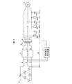
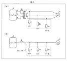
- FIG. 2 is a schematic system diagram illustrating a configuration example to which the leakage current calculation apparatus 1 according to the first embodiment of the present invention is applied.
- the leakage current calculation device 1 is configured to monitor a three-phase motor 5 (load) such as a servo motor driven by an inverter 3 that uses a commercial power system 2 as a power source.
- load such as a servo motor driven by an inverter 3 that uses a commercial power system 2 as a power source.
- the commercial power system 2 is a three-phase AC type AC power source in which the S phase is grounded to the ground E among different three phases (R phase, S phase, T phase). These three phases are respectively connected to the input side of the inverter 3 via R line, S line, and T line.
- the inverter 3 generates a predetermined control voltage from the three-phase power supplied from the commercial power system 2 and corresponds to the three phases (U phase, V phase, W phase) on the output side (U line, V line). , W line) to the three-phase motor 5 respectively.
- the three-phase motor 5 is connected to the output side of the inverter 3 and operates using each supplied control voltage.
- a zero-phase current transformer 4 surrounding the U line, the V line, and the W line is provided.
- the zero-phase current transformer 4 measures a three-phase synthesized ground zero-phase current I 0 that flows between the inverter 3 and the three-phase motor 5. As will be described in detail later, this zero-phase current I0 is equal to a leakage current flowing between the three-phase motor 5 and the ground E.
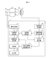
- FIG. 1 is a block diagram showing a main configuration of a leakage current calculation apparatus according to Embodiment 1 of the present invention.
- the leakage current calculation device 1 includes a voltage measurement unit 11, a leakage current measurement unit 12, a ground voltage calculation unit 13, a system frequency component extraction unit 14 (frequency component extraction unit), and a phase difference calculation unit 15 ( (Phase difference determination unit), circle center calculation unit 16, resistance leakage current calculation unit 17 (leakage current calculation unit), insulation resistance calculation unit 18, determination unit 19 (insulation degradation load identification unit, insulation degradation determination unit), and output
- the unit 20 is provided.
- the voltage measurement unit 11 measures at least one of the line voltages on the input side of the inverter 3. In this embodiment, the line voltage between the R phase and the S phase on the input side of the inverter 3 is measured.
- the line voltage to be measured is not limited to this, and may be any line voltage.
- the voltage measuring unit 11 may measure a voltage between the R phase and the T phase, or a voltage between the T phase and the S phase.
- the voltage measurement unit 11 may have a low-pass filter or a band-pass filter for removing high frequency components from the measured voltage or extracting system frequency components.
- the ground voltage calculation unit 13 calculates the ground voltage between the neutral point of the commercial power system 2 and the ground E from at least one of the line voltages measured by the voltage measurement unit 11. In the present embodiment, the ground voltage is calculated from the line voltage between RS.
- the leakage current measuring unit 12 measures a leakage current (zero-phase current) flowing between the three-phase motor 5 and the ground E through the zero-phase current transformer 4.
- the leakage current measuring unit 12 may have a low-pass filter or a band-pass filter for removing a high frequency component from the measured leakage current or extracting a system frequency component.
- the system frequency component extraction unit 14 extracts a leakage current component synchronized with the system frequency of the commercial power system 2 (that is, a leakage current component having the same frequency as the system frequency) from the measured leakage current.
- a leakage current component synchronized with the system frequency of the commercial power system 2 (that is, a leakage current component having the same frequency as the system frequency) from the measured leakage current.
- DFT Discrete Fourier Transform
- FFT Fast Fourier Transform
- the phase difference calculation unit 15 calculates the phase difference between the calculated ground voltage and the extracted leakage current component.
- the calculation of the phase difference is performed by, for example, arithmetic processing. Instead, the phase difference may be determined by measuring the phase difference using a predetermined measurement circuit.
- the circle center calculation unit 16 calculates the center point of the circle drawn by each point (specific point) specified by the leakage current component calculated at at least three different time points and the determined phase difference.
- the resistance component leakage current calculation unit 17 is a current that flows between the three-phase motor 5 and the ground E through the ground insulation resistance of the three-phase motor 5 (the ground insulation resistance component for the system frequency). Leakage current) is calculated.
- the insulation resistance calculation unit 18 calculates the ground insulation resistance of the three-phase motor 5 by using the ground insulation resistance leakage current corresponding to the calculated system frequency and the calculated ground voltage.
- the determination unit 19 determines the presence or absence of insulation failure (insulation deterioration) of the three-phase motor 5 based on the leakage current or the ground insulation resistance corresponding to the calculated ground frequency for the system frequency.
- the output unit 20 outputs the determination result of the insulation failure to the outside of the leakage current calculation device 1 in a desired form. This output is performed as, for example, screen display, communication output, or contact signal output.
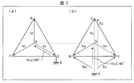
- FIG. 3 is a diagram for explaining the principle for calculating the ground voltage of the commercial power system 2 in Embodiment 1 of the present invention.
- the leakage current calculation apparatus 1 calculates a voltage (ground voltage) applied to the ground insulation resistance of the three-phase motor 5 in order to calculate the ground insulation resistance of the three-phase motor 5. This ground voltage calculation method will be described below with reference to FIG.
- the ground voltage applied to the ground insulation resistance of the three-phase motor 5 is equal to the voltage between the neutral point (N phase) of the commercial power system 2 and the ground E.
- the S phase (S line) is grounded as shown in FIG. Since the voltage of the S phase with respect to the neutral point is the system voltage Vs between the N phase and the S phase, the voltage between the N phase and the ground E is 180 ° in phase with the system voltage Vs. The voltage Vs is 180 °.
- the potential of the neutral point N of the inverter 3 is equal to the potential of the neutral point N of the commercial power system 2 as shown in FIG. Therefore, the voltage between the neutral point N of the inverter 3 and the ground E is also equal to the ground voltage Vs ⁇ 180 ° of the commercial power system 2.
- the U-phase ground voltage Eu is obtained by adding Vs ° 180 ° to the voltage Vu between the N-phase and the U-phase.
- the V-phase ground voltage Ev is obtained by adding Vs ⁇ 180 ° to the voltage Vv between the N-phase and the V-phase.
- the RS line voltage is a vector sum of the voltage Vr between the neutral point (N phase) and the R phase and the ground voltage Vs.
- the ground voltage calculation unit 13 can calculate the system voltage Vs of the commercial power system 2 by dividing the measured RS line voltage by ⁇ 3.
- the system voltage Vs and the ground voltage Vs ⁇ 180 ° are voltages whose effective values are equal to each other and whose phases are shifted from each other by 180 °. Therefore, the ground voltage calculation unit 13 can calculate the ground voltage Vs ⁇ 180 ° by shifting the phase of the calculated system voltage Vs by 180 °.
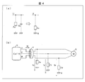
- FIG. 4 is a diagram for explaining a leakage current flowing between the three-phase motor 5 and the ground E in the first embodiment of the present invention.
- the ground insulation resistance and ground stray capacitance of the three-phase motor 5 are impedance components between the wiring or coil of the three-phase motor 5 and the ground E. These are connected in parallel to each other. Therefore, as shown in FIG. 4A, the ground insulation resistance Ru and the ground stray capacitance Cu between the U phase and the ground E on the output side of the inverter 3 are both between the U phase and the ground E. It is a component constituting the impedance Zu between them.
- ground insulation resistance Rv and the ground stray capacitance Cv between the V phase and the ground E are components that constitute the impedance Zv between the V phase and the ground E.
- ground insulation resistance Rw and the ground stray capacitance Cw between the W phase and the ground E are components that constitute the impedance Zw between the W phase and the ground E.
- leakage current flows through each phase on the output side of the inverter 3. Specifically, the leakage current Iu flows through the U phase, the leakage current Iv flows through the V phase, and the leakage current Iw flows through the W phase.
- the leakage current I0 As described above, the zero-phase current I 0 measured through the zero-phase current transformer 4 is equal to the leakage current flowing through the combined impedance of the three-phase motor 5. Therefore, in the following, the leakage current may be referred to as leakage current I0.
- FIG. 5 is a diagram illustrating the ground insulation resistance between the three-phase motor 5 and the ground E according to the first embodiment of the present invention.
- the ground voltage Vs ⁇ 180 ° is applied to each phase (U, V, W) on the output side of the inverter 3 in the same phase.
- the ground combined impedance Z0 includes the ground insulation resistance and the ground stray capacitance of the three-phase motor 5 connected in parallel with each other as components. Therefore, the current I0r flowing through the ground insulation resistance in Z0 is I0 ⁇ cos ⁇ , where ⁇ is the phase difference between the zero-phase current I0 and the ground voltage Vs ⁇ 180 °. On the other hand, the current I0c flowing through the ground stray capacitance in Z0 is I0 ⁇ sin ⁇ .
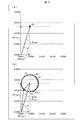
- FIG. 6 is a diagram for explaining the principle for the leakage current calculation apparatus 1 according to the first embodiment of the present invention to calculate the leakage current synchronized with the system frequency of the commercial power system 2.
- the leakage current I0 measured by the leakage current measuring unit 12 includes a component (I0_sys) synchronized with the system frequency of the commercial power system 2 and a component (I0_inv) synchronized with the operation frequency of the inverter 3.
- I0_sys a component synchronized with the system frequency of the commercial power system 2
- I0_inv a component synchronized with the operation frequency of the inverter 3.
- the frequency (system frequency) of the voltage that the commercial power system 2 supplies to the inverter 3 is 60 Hz
- the frequency (operation frequency) of the voltage that the inverter 3 drives the three-phase motor 5 is 50 Hz. is there. That is, both frequency settings are different from each other.
- the system frequency component extraction unit 14 extracts only the leakage current I0_sys of the system frequency component from the measured leakage current I0 by executing a calculation process that extracts a leakage current having the same frequency as the system frequency. . Since the system frequency and the operation frequency are different, in this extraction process, the component synchronized with the system frequency is extracted, but the component synchronized with the operation frequency is not extracted. Thereby, the extracted leakage current I0_sys does not include the leakage current I0_inv synchronized with the operation frequency component of the inverter 3.
- the impedance between the three-phase motor 5 and the ground E includes both ground insulation resistance and ground stray capacitance.
- the phase of the measured leakage current I0 is shifted from the phase of the ground voltage Vs ⁇ 180 ° due to the influence of the ground stray capacitance. . Therefore, the phase difference ⁇ of the leakage current I0_sys extracted from the leakage current I0 is also shifted from the phase of the ground voltage Vs ⁇ 180 °.
- the leakage current component extracted from the leakage current I0 includes only the leakage current I0_sys. Therefore, the phase difference ⁇ between the ground voltage VsV180 ° and the leakage current component (I0_sys itself) is always equal regardless of the time of measurement.
- a vector connecting the origin of the plane coordinate system and the point where the end point P0 is projected on the vertical axis of the plane coordinate system corresponds to the capacity leakage current I0C_sys of the system frequency component with high accuracy. That is, the value of this projection point is the effective value of I0C_sys.
- the leakage current calculation device 1 extracts a component synchronized with the system frequency from the measured leakage current I0.
- the leakage current I0_sys for the system frequency can be calculated with high accuracy.
- the ground insulation resistance of the three-phase motor 5 can be accurately calculated by using the ground voltage Vs ⁇ 180 ° and the leakage current I0R_sys.
- the end point when the leakage current I0 is expressed in vector is not fixed to one point, and the position changes at each measurement time point. .
- the leakage current extracted by the system frequency component extraction unit 14 includes both the leakage current I0_sys for the system frequency and the leakage current I0_inv for the operating frequency.
- the system frequency component extraction unit 14 cannot distinguish between the component synchronized with the system frequency included in the leakage current I0 and the component synchronized with the operation frequency. Therefore, when the system frequency component extraction unit 14 executes a process of extracting a component synchronized with the system frequency from the leakage current I0, as a result, the leakage current I0_sys synchronized with the system frequency and the leakage current I0_inv synchronized with the operation frequency are obtained. The mixed leakage current I0_mix is extracted.
- the vector drawn in the plane coordinate system is a composite vector (I0_mix vector) of the I0_sys vector and the I0_inv vector.
- I0_mix vector the position of the end point of this composite vector is determined at each measurement time point, such as point P1 (specific point), point P2 (specific point), and point P3 (specific point) due to the influence of I0_inv. Change. Specifically, as shown in FIG. 6B, this change occurs so that each end point draws a circle 61.
- the end point of the vector is not determined to be a single point. Therefore, the resistance leakage current I0R_sys of the system frequency component is accurately calculated based on this end point. I can't do it. In other words, even if I0R_sys is calculated based on the end point, the value fluctuates at each measurement time, and thus an accurate value cannot be specified.
- FIG. 7 is a diagram for explaining the principle of rotation of the end point when the extracted leakage current component is expressed in vector when the system frequency and the operation frequency match in Embodiment 1 of the present invention.
- the system frequency and the operating frequency are slightly different from each other even if they are set to the same value. For example, even when each is set to 60 Hz, the system frequency is 60.00 Hz, while the operating frequency is 60.01 Hz, so that there is a slight deviation from each other. Due to this frequency shift, as shown in FIG. 7A, the waveform 71 of I0_sys and the waveform 72 of I0_inv are slightly shifted from each other as the measurement time point gradually changes to P1, P2, and P3. go.
- the leakage current I0_mix extracted from the leakage current I0 includes the leakage current I0_sys for the system frequency and the leakage current I0_inv for the operation frequency.
- the determined phase difference ⁇ is a phase difference between the ground voltage Vs ⁇ 180 ° and the leakage current I0_mix
- a shift occurs between the waveform of I0_sys and the waveform of I0_inv included in the leakage current I0_inv.
- the value of the phase difference ⁇ shifts with time.
- the position of the end point when the leakage current I0_mix is expressed in vector also changes with time.
- the positions of the end points (specific points) P1 to P3 of the leakage current I0 change corresponding to the waveform shifts of P1 to P3 in FIG.
- the end point of I0_mix draws a circle 73 with time as shown in FIG. That is, P1 to P3 are plotted on the circle 73 in principle.
- the end point of I0_sys matches the center point 74 of the circle 73. Therefore, the leakage current calculation apparatus 1 according to the present embodiment calculates the center point 74 and further projects the center point 74 on the horizontal axis and the vertical axis of the plane coordinate axis, thereby calculating I0R_sys and I0C_inv with high accuracy.
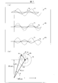
- FIG. 8 is a diagram illustrating a first method for calculating a ground insulation resistance component leakage current according to the first embodiment of the present invention.
- the system frequency component extraction unit 14 extracts I0_mix at three different time points.
- the phase difference calculation unit 15 calculates the phase difference ⁇ at three different time points.
- the circle center calculation unit 16 calculates points P1 to P3 which are end points when each I0_mix is expressed in vector based on the leakage current I0_mix and the phase difference ⁇ determined at the three time points.
- the circle center calculation unit 16 calculates the outer center of the triangle 81 having these points as vertices instead of directly calculating the circle 82 passing through these points P1 to P3. This outer center coincides with the center point 83 of a circle 82 circumscribing the triangle 81. As described above, in the example of FIG. 8, the circle center calculation unit 16 can calculate the center point 83 of the circle 82 passing through these points by calculating the outer center of the triangle 81 having P1 to P3 as vertices. it can.
- the circle center calculation unit 16 outputs the calculated center point 83 to the resistance leakage current calculation unit 17.
- the vector having the origin of the plane coordinate system as the start point and the center point 83 as the end point is nothing but the leak current I0_sys for the system frequency in the leak current I0_mix extracted from the leak current I0. Therefore, the resistance component leakage current calculation unit 17 can calculate the leakage current I0R_sys corresponding to the ground insulation resistance out of the leakage current I0_sys corresponding to the system frequency by projecting the calculated center point 83 on the horizontal axis.
- the resistance leakage current calculation unit 17 outputs the calculated I0R_sys to the insulation resistance calculation unit 18.
- the insulation resistance calculator 18 calculates the ground insulation resistance of the three-phase motor 5 using the leakage current I0R_sys and the ground voltage Vs ⁇ 180 °.
- the center point 83 is calculated using only the three points P1 to P3. That is, in order to calculate I0R_sys, it suffices to measure the leakage current I0 at three different time points, so that I0R_sys can be calculated at high speed.
- FIG. 9 is a diagram illustrating a second method for calculating the ground insulation resistance leakage current according to the first embodiment of the present invention.
- the system frequency component extracting unit 14 extracts I0_mix at four or more different time points.
- the phase difference calculation unit 15 calculates the phase difference ⁇ at four or more different time points.
- the circle center calculation unit 16 calculates an equation of a circle 91 that passes through each of these points Pn. Then, using this equation, the center point 92 of the circle 91 is calculated. In the example of FIG. 9, the circle center calculation unit 16 calculates the equation of the circle 91 by the least square method of the circle using the calculated points Pn. More specific description will be given below.
- FIG. 10 is a diagram for explaining the least square method of a circle according to the first embodiment of the present invention.
- each point Pn is calculated as a point P1 (x1, y1), a point P2 (x2, y2), a point P3 (x3, y3), a point P4 (x4, y4),.
- the calculation of the leakage current I0_sys for the ground insulation resistance based on the center point 92 and the calculation of the ground insulation resistance of the three-phase motor 5 based on the leakage current I0_sys and the ground voltage Vs ⁇ 180 ° are the same as the above-described example.
- the center point 92 of the circle 91 can be calculated with higher accuracy. Therefore, the leakage current I0_sys and the ground insulation resistance can be calculated with higher accuracy.
- FIG. 9B shows an example of the actual calculation result of I0_sys.
- the center point 92 determined from this equation is projected on the horizontal axis, the value is 4.4 mA, and thus 4.4 mA is calculated as I0R_sys.
- the ground insulation resistance of the three-phase motor 5 calculated using 4.4 mA of I0_sys is 26.9 k ⁇ , which also agrees well with the theoretical value of 27 k ⁇ .
- FIG. 11 is a diagram for explaining a third method for calculating the ground insulation resistance leakage current according to the first embodiment of the present invention.
- the system frequency component extraction unit 14 does not directly calculate the center point of the circle, but instead, the minimum value of the leakage current corresponding to the ground insulation resistance at I0_mix and the I0_mix within a certain time. Among these, the maximum value of the leakage current corresponding to the ground insulation resistance is calculated, and an intermediate value thereof is calculated as I0R_sys.
- the system frequency component extraction unit 14 extracts I0_mix at each time point within a fixed time (preferably a long time of 60 seconds or more), that is, until a point equal to or more than one circle is calculated.
- the phase difference calculation unit 15 calculates the phase difference ⁇ at each time point until points equal to or more than one circle are calculated.
- the circle center calculation unit 16 does not calculate the center of the circle.
- the insulation resistance calculation unit 18 executes the calculation of I0R_mix at each time point over a long time (60 seconds or more).
- the value of I0R_mix coincides with the value on the horizontal axis at the point where the end point when I0_mix is expressed in vector is projected on the horizontal axis. Since the end point draws a circle as described above, a point obtained by projecting the end point on the horizontal axis is always in a line obtained by projecting the entire circle on the horizontal axis. Therefore, the calculated minimum value 111 and the maximum value 112 corresponding to the end of the line are naturally determined in the calculated I0R_mix.
- the intermediate value 113 between the minimum value 111 and the maximum value 112 corresponds to the center point of the circle. To do. As described above, the value obtained by projecting the center point of the circle on the horizontal axis corresponds to I0R_sys. Therefore, the resistance leakage current calculation unit 17 can calculate I0R_sys by calculating the intermediate value 113.
- I0R_sys can be obtained by simple calculation.
- FIG. 11B shows an example of the actual calculation result of I0R_sys by the third method.
- 4.3 mA was calculated as the intermediate value 113, that is, I0R_sys.
- the ground insulation resistance of the three-phase motor 5 calculated using I0R_sys of 4.3 mA is 27.1 k ⁇ , which is in good agreement with the theoretical value of 27 k ⁇ .
- Embodiment 2 With reference to FIG. 12 and FIG. 13, Embodiment 2 which concerns on this invention is demonstrated below. Each member common to Embodiment 1 described above is denoted by the same reference numeral, and detailed description thereof is omitted.
- FIG. 12 is a schematic system diagram illustrating a configuration example to which the leakage current calculation apparatus 1 according to the second embodiment of the present invention is applied.
- the configuration of the leakage current calculation device 1 is basically the same as that of the first embodiment.
- one leakage current calculation device 1 can monitor each of the plurality of three-phase motors 5a and 5b.
- the three-phase motors 5a and 5b are driven by inverters 3a and 3b, respectively.
- the input sides of the inverters 3a and 3b are both connected to the common commercial power system 2.
- the output side of the inverter 3a is connected to the three-phase motor 5a, while the output side of the inverter 3b is connected to the three-phase motor 5b.
- a zero-phase current transformer 4a is disposed between the inverter 3a and the three-phase motor 5a, while a zero-phase current transformer 4b is disposed between the inverter 3b and the three-phase motor 5b.
- These zero-phase current transformers 4 a and 4 b are both connected to the leakage current measuring unit 12 of the leakage current calculating device 1.
- the leakage current calculation device 1 calculates a ground insulation resistance leakage current and a ground insulation resistance corresponding to each of the three-phase motors 5a and 5b. The procedure will be described below.
- the voltage measuring unit 11 measures at least one of the line voltages on the input side of any one of the plurality of inverters 3a and 3b. Since the input sides of the inverters 3a and 3b are connected to the common commercial power system 2, for example, the voltage Rs between the R phase and the S phase of the inverter 3a is the voltage between the R phase and the S phase of the inverter 3b. Is exactly equal to Rs. As described above, in the present embodiment, the voltage Rs needs to be measured only at one place, so that the configuration of the leakage current calculation apparatus 1 can be further simplified.
- the ground voltage calculation unit 13 calculates the ground voltage Vs ⁇ 180 ° based on the voltage Rs measured from the input side of the inverter 3a. Since voltage Rs is common to inverters 3a and 3b, leakage current calculation device 1 uses voltage Vs ⁇ ⁇ 180 ° as a ground voltage common to three-phase motor 5a and three-phase motor 5b in the following processing.
- the leakage current measuring unit 12 measures the leakage current of the three-phase motor 5a through the zero-phase current transformer 4a, and measures the leakage current of the three-phase motor 5b through the zero-phase current transformer 4b. That is, the leakage current calculation device 1 includes one leakage current measuring unit 12 that is common to the three-phase motors 5a and 5b.
- the leakage current calculation device 1 may include a plurality of leakage current measuring units 12a and 12b corresponding to the three-phase motors 5a and 5b, respectively.
- the leakage current measuring unit 12a is connected to the zero-phase current transformer 4a
- the leakage current measuring unit 12b is connected to the zero-phase current transformer 4b.
- the leakage current measurement unit 12a measures the leakage current of the three-phase motor 5a through the zero-phase current transformer 4a
- the leakage current measurement unit 12b calculates the leakage current of the three-phase motor 5b through the zero-phase current transformer 4b. measure.
- the system frequency component extraction unit 14 extracts a leakage current component corresponding to the three-phase motor 5a from the leakage current of the three-phase motor 5a.
- a leakage current component corresponding to the three-phase motor 5b is extracted from the leakage current of the three-phase motor 5b.
- the phase difference calculation unit 15 calculates the phase difference between the calculated ground voltage and the leakage current component of the three-phase motor 5a. Furthermore, the phase difference between the calculated ground voltage and the leakage current component of the three-phase motor 5b is calculated.
- the resistance leakage current calculation unit 17 calculates a ground insulation resistance leakage current of the three-phase motor 5a based on the center point of the circle corresponding to the three-phase motor 5a. Further, the leakage current corresponding to the ground insulation resistance of the three-phase motor 5b is calculated based on the center point of the circle corresponding to the three-phase motor 5b.
- the insulation resistance calculation unit 18 calculates the ground insulation resistance of the three-phase motor 5a from the ground voltage Vs ⁇ 180 ° and the leakage current corresponding to the ground insulation resistance of the three-phase motor 5a. Further, the ground insulation resistance of the three-phase motor 5b is calculated from the ground voltage Vs ⁇ 180 ° and the leakage current corresponding to the ground insulation resistance of the three-phase motor 5b.
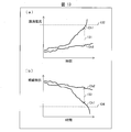
- FIG. 13 is a diagram illustrating an example of a temporal transition of the ground insulation resistance-divided leakage current or the calculated value of the ground insulation resistance for each of the three-phase motors 5 according to the second embodiment of the present invention.
- (A) of FIG. 13 shows the time transition of each earth insulation resistance part leakage current of each of the three-phase motors 5a and 5b.
- Ch1 corresponds to the three-phase motor 5a
- Ch2 corresponds to the three-phase motor 5b.
- FIG. 13B shows the temporal transition of the ground insulation resistance of each of the three-phase motors 5a and 5b.
- Ch1 corresponds to the three-phase motor 5a
- Ch2 corresponds to the three-phase motor 5b.
- the three-phase motors 5a and 5b have different temporal changes in the ground insulation resistance-divided leakage current or the ground insulation resistance, respectively.
- the leakage current calculation device 1 can appropriately identify the three-phase motor 5 that has undergone insulation degradation by comparing values with each other or by comparing each value with a predetermined threshold value.
- the determination unit 19 compares the ground insulation resistance leakage current corresponding to the system frequency of the three-phase motor 5a with the ground insulation resistance leakage current corresponding to the system frequency of the three-phase motor 5b.
- the degree of insulation deterioration in 5b can be determined respectively. For example, in the example of FIG. 13 (a), the ground insulation resistance leakage current corresponding to the system frequency of the three-phase motor 5a at a certain time and the ground insulation resistance leakage current corresponding to the system frequency of the three-phase motor 5b at the same time. A large degree of divergence 131 occurs between the two.
- the determination unit 19 detects the degree of divergence 131, the determination unit 19 determines that the three-phase motor 5 a having a larger leakage current with respect to the ground insulation resistance has deteriorated the insulation.
- the determination unit 19 can also identify the three-phase motor 5a in which the leakage current corresponding to the ground insulation resistance exceeds the specified threshold among the three-phase motors 5a and 5b as the three-phase motor 5a that has undergone insulation degradation. For example, in FIG. 13A, since the threshold current 132 is exceeded after a point in time when the leakage current for the ground insulation resistance of the three-phase motor 5a is present, the determination unit 19 causes the three-phase motor 5a to undergo insulation deterioration after this point. Can be identified.
- the determination using the above-described divergence or threshold value is performed not only on the ground insulation resistance component leakage current but also on the ground insulation resistances of the three-phase motors 5a and 5b as shown in FIG. 13B. be able to.
- a large degree of divergence 133 occurs between the ground insulation resistance of the three-phase motor 5a at a certain time point and the ground insulation resistance of the three-phase motor 5b at the same time point.
- the determination unit 19 determines that the three-phase motor 5a having a smaller ground insulation resistance is deteriorated in insulation.
- the determination unit 19 determines that the three-phase motor 5a has undergone insulation deterioration after this point. Can be specified.
- the leakage current calculation device 1 includes a plurality of leakage current measuring units 12, the leakage current measuring unit 12 for measuring the leakage current of the three-phase motor 5 that is not a monitoring target is not necessary.
- the leakage current calculation device 1 having such an unnecessary leakage current measurement unit 12 leads to a wasteful cost increase of the leakage current calculation device 1.
- each leakage current measuring unit 12 may be an extension unit for measuring the leakage current.
- a technique disclosed in Japanese Patent Application Laid-Open Publication No. 2013-181813 may be used.
- the leakage current calculation apparatus has an input side of an inverter whose power source is a three-phase AC commercial power system in which one of different three phases is grounded.
- a voltage measurement unit that measures at least one of the line voltages in the line, and a ground between the neutral point of the commercial power system and the ground from at least one of the line voltages measured by the voltage measurement unit
- a ground voltage calculation unit for calculating a voltage
- a leakage current measurement unit for measuring a leakage current flowing between the load connected to the output side of the inverter and the ground, and the commercial power system from the measured leakage current
- a frequency component extraction unit that extracts a leakage current component that is synchronized with the system frequency
- a phase difference determination unit that determines a phase difference between the calculated ground voltage and the extracted leakage current component, and The ground isolation of the load between the load and the ground based on the center point of the circle drawn by the specific points identified by the leakage current component extracted at three different time points and the determined phase difference
- a leakage current calculation unit for calculating a leakage current corresponding to the ground insulation resistance corresponding to the system frequency flowing through the resistor.
- the leakage current component extracted from the leakage current includes both the leakage current synchronized with the grid frequency and the leakage current synchronized with the operation frequency. ing. Since the frequencies of the two do not exactly match each other and are slightly shifted from each other, the phase difference between the ground voltage and the leakage current component is shifted from each other at each measurement time point. Therefore, the point defined by the leakage current component and the phase difference changes at each measurement time and draws a circle.
- the leakage current calculation device is based on the center point of a circle drawn by each specific point specified by the leakage current component extracted at the three different time points and the calculated phase difference, The leakage current corresponding to the ground insulation resistance corresponding to the system frequency flowing between the load and the ground through the ground insulation resistance of the load is calculated.
- the center point of this circle corresponds to the end point of the vector representing the leakage current corresponding to the system frequency included in the leakage current component. Therefore, the leakage current calculation device can accurately calculate the leakage current corresponding to the ground insulation resistance out of the leakage current corresponding to the system frequency based on the center point.
- the leakage current calculation apparatus when the system frequency of the commercial power system matches the operation frequency of the inverter device, the leakage current corresponding to the ground insulation resistance corresponding to the system frequency Can be calculated with high accuracy.
- a leakage current calculation device is the leakage current calculation apparatus according to aspect 1, wherein the leakage current is calculated on the output side of the inverter based on the calculated ground voltage and the calculated ground insulation resistance component leakage current corresponding to the system frequency.
- a ground insulation resistance calculation unit for calculating a ground insulation resistance of the load is further provided.
- the ground insulation resistance of the load can be calculated with higher accuracy.
- the leakage current calculation device is the leakage current calculation apparatus according to aspect 1 or 2, wherein the leakage current calculation unit is based on an equation of a circumscribed circle circumscribing a triangle defined by the three specific points. It is characterized by specifying the center point.
- the ground resistance leakage current corresponding to the system frequency can be calculated at higher speed.
- the leakage current calculation apparatus is characterized in that, in the aspect 1 or 2, the leakage current calculation unit specifies a center point of the circle based on a least square method of the circle.
- the ground resistance leakage current corresponding to the system frequency can be calculated with higher accuracy.
- the leakage current calculation apparatus is the leakage current calculation device according to Aspect 1 or 2, wherein the leakage current calculation unit is configured to extract the leakage current component extracted at each time point within a predetermined time and the determined phase difference. Based on the calculated values, the ground insulation resistance leakage current at each time point is calculated, and the intermediate value between the maximum and minimum values is calculated as the ground insulation resistance leakage current for the system frequency. It is characterized by doing.
- each of the plurality of loads is individually connected to the output side of each of the plurality of inverters.
- Each of the input sides is connected to the same commercial power system, and the voltage measurement unit measures at least one of the line voltages on the input side of any of the plurality of inverters,
- the leakage current measurement unit measures a plurality of leakage currents corresponding to each of the plurality of loads, and the frequency component extraction unit applies each of the plurality of measured leakage currents to each of the plurality of loads.
- a plurality of phase differences, and the leakage current calculation unit is configured to ground isolation for a plurality of system frequencies corresponding to each of the loads based on center points of the plurality of circles corresponding to the plurality of loads. It is characterized by calculating a resistance leakage current.
- the ground resistance component leakage current corresponding to the system frequency of a plurality of different loads can be calculated by one leakage current calculation device. Moreover, since the voltage measurement by the voltage measurement unit may be performed at any one of the plurality of inverters, the voltage can be measured only at one place. Thereby, the configuration of the leakage current calculation device can be further simplified.
- the leakage current calculation apparatus is the leakage current calculation apparatus according to Aspect 6, in which the load having a leakage current corresponding to the ground insulation resistance corresponding to the system frequency exceeds a predetermined threshold among the plurality of loads.
- An insulation degradation load identifying unit that identifies the degraded load is further provided.
- the leakage current calculation apparatus compares the ground insulation resistance leakage currents corresponding to the plurality of system frequencies with each other to thereby determine the degree of insulation deterioration in the plurality of loads. It further comprises an insulation deterioration determining unit for determining each.
- a leakage current calculation method is provided on the input side of an inverter that uses a three-phase AC commercial power system that is grounded as one of three different phases.
- a voltage measurement step for measuring at least one of the line voltages in the line, and a ground voltage for calculating a ground voltage between the neutral point of the commercial power system and the ground from the measured line voltage
- a voltage calculation step for measuring a leakage current flowing between the load connected to the output side of the inverter and the ground, and a system frequency of the commercial power system from the measured leakage current
Landscapes
- Physics & Mathematics (AREA)
- General Physics & Mathematics (AREA)
- Nonlinear Science (AREA)
- Mathematical Physics (AREA)
- Engineering & Computer Science (AREA)
- Power Engineering (AREA)
- Testing Of Short-Circuits, Discontinuities, Leakage, Or Incorrect Line Connections (AREA)
- Tests Of Circuit Breakers, Generators, And Electric Motors (AREA)
- Emergency Protection Circuit Devices (AREA)
- Measurement Of Current Or Voltage (AREA)
Priority Applications (4)
| Application Number | Priority Date | Filing Date | Title |
|---|---|---|---|
| KR1020187004138A KR102007909B1 (ko) | 2016-03-09 | 2016-11-21 | 누설 전류 산출 장치 및 누설 전류 산출 방법 |
| CN201680047997.3A CN107923936B (zh) | 2016-03-09 | 2016-11-21 | 漏电流计算装置及漏电流计算方法 |
| US15/751,468 US10782359B2 (en) | 2016-03-09 | 2016-11-21 | Leakage current calculation device and leakage current calculation method |
| EP16893595.5A EP3428664B1 (de) | 2016-03-09 | 2016-11-21 | Leckstromberechnungsvorrichtung und leckstromberechnungsverfahren |
Applications Claiming Priority (2)
| Application Number | Priority Date | Filing Date | Title |
|---|---|---|---|
| JP2016046127A JP6477548B2 (ja) | 2016-03-09 | 2016-03-09 | 漏洩電流算出装置および漏洩電流算出方法 |
| JP2016-046127 | 2016-03-09 |
Publications (1)
| Publication Number | Publication Date |
|---|---|
| WO2017154271A1 true WO2017154271A1 (ja) | 2017-09-14 |
Family
ID=59790324
Family Applications (1)
| Application Number | Title | Priority Date | Filing Date |
|---|---|---|---|
| PCT/JP2016/084416 WO2017154271A1 (ja) | 2016-03-09 | 2016-11-21 | 漏洩電流算出装置および漏洩電流算出方法 |
Country Status (6)
| Country | Link |
|---|---|
| US (1) | US10782359B2 (de) |
| EP (1) | EP3428664B1 (de) |
| JP (1) | JP6477548B2 (de) |
| KR (1) | KR102007909B1 (de) |
| CN (1) | CN107923936B (de) |
| WO (1) | WO2017154271A1 (de) |
Cited By (3)
| Publication number | Priority date | Publication date | Assignee | Title |
|---|---|---|---|---|
| WO2018193703A1 (ja) * | 2017-04-21 | 2018-10-25 | オムロン株式会社 | 漏洩電流算出装置および漏洩電流算出方法 |
| TWI696838B (zh) * | 2018-03-29 | 2020-06-21 | 日商歐姆龍股份有限公司 | 絕緣測量裝置及絕緣測量方法 |
| WO2020217880A1 (ja) * | 2019-04-26 | 2020-10-29 | 株式会社日立製作所 | 電気機械の診断方法および診断装置、並びに回転電機 |
Families Citing this family (5)
| Publication number | Priority date | Publication date | Assignee | Title |
|---|---|---|---|---|
| EP3370073B1 (de) * | 2017-03-01 | 2020-04-29 | ABB Power Grids Switzerland AG | Verfahren und vorrichtung zur bestimmung der parameter kapazitiver komponenten |
| US11606022B2 (en) * | 2018-01-29 | 2023-03-14 | Toshiba Mitsubishi-Electric Industrial Systems Corporation | Insulation deterioration monitoring apparatus and insulation deterioration monitoring method |
| KR102124554B1 (ko) * | 2019-01-25 | 2020-06-18 | 한국전기안전공사 | 실시간 원격 3상 전기설비의 활선상태 누전감시 장치 및 방법 |
| DE102019107399A1 (de) * | 2019-03-22 | 2020-09-24 | Vega Grieshaber Kg | Feldgerät mit Überwachungsvorrichtung und Verfahren zum Betreiben eines Feldgerätes |
| CN111768599B (zh) * | 2020-07-08 | 2021-08-10 | 安徽先兆科技有限公司 | Ac380v回路电气安全管控方法及系统 |
Citations (3)
| Publication number | Priority date | Publication date | Assignee | Title |
|---|---|---|---|---|
| WO2006035519A1 (ja) * | 2005-01-31 | 2006-04-06 | Ohno, Takemi | 漏洩電流遮断装置及び方法 |
| JP2011153910A (ja) * | 2010-01-27 | 2011-08-11 | Patokkusu Japan Kk | 電気機器おける漏洩電流測定装置及び測定方法 |
| JP5631444B1 (ja) * | 2013-05-27 | 2014-11-26 | タナシン電機株式会社 | 漏洩電流算出装置及び漏洩電流算出方法 |
Family Cites Families (15)
| Publication number | Priority date | Publication date | Assignee | Title |
|---|---|---|---|---|
| JPS53100350A (en) | 1977-02-15 | 1978-09-01 | Nifco Inc | Fastener for jointing two panels |
| US6421618B1 (en) * | 1998-12-28 | 2002-07-16 | General Electric Company | Incipient leakage current fault detection apparatus and method |
| ES2255549T3 (es) * | 2000-04-17 | 2006-07-01 | Suparules Limited | Dispositivo de medicion de corriente. |
| JP3652584B2 (ja) | 2000-06-08 | 2005-05-25 | 光商工株式会社 | 低圧接地電路の漏電検出保護方法と装置 |
| CN2502278Y (zh) * | 2001-08-02 | 2002-07-24 | 南京普天通信股份有限公司 | 工频电流监测器 |
| JP2007114190A (ja) | 2005-09-20 | 2007-05-10 | Daihen Corp | 漏洩電流抵抗分検出方法及びその装置 |
| CN1963539B (zh) * | 2005-11-09 | 2011-03-09 | 李岩松 | 光学电流互感器及其测定电流的方法 |
| JP2009115754A (ja) | 2007-11-09 | 2009-05-28 | Sbc Co Ltd | 電気機器における漏洩電流測定装置及び測定方法 |
| CN101271130A (zh) * | 2008-01-24 | 2008-09-24 | 武汉格蓝若光电互感器有限公司 | 点阵式霍尔电流传感器 |
| JP5618910B2 (ja) * | 2011-06-01 | 2014-11-05 | 三菱電機株式会社 | 絶縁劣化監視システム |
| JP6222722B2 (ja) | 2012-02-22 | 2017-11-01 | 株式会社三和技術総合研究所 | 電力及び漏洩電流測定装置並びにその測定方法 |
| JP5942506B2 (ja) * | 2012-03-15 | 2016-06-29 | オムロン株式会社 | 漏電検出器 |
| CN102739066B (zh) * | 2012-06-20 | 2014-12-31 | 中国计量科学研究院 | 一种感应式电流电压变换器及实现高频电流测量的方法 |
| JP5705382B1 (ja) | 2013-11-22 | 2015-04-22 | 三菱電機株式会社 | 絶縁検出器及び電気機器 |
| JP5770903B1 (ja) | 2014-09-26 | 2015-08-26 | タナシン電機株式会社 | 漏洩電流算出装置及び漏洩電流算出方法 |
-
2016
- 2016-03-09 JP JP2016046127A patent/JP6477548B2/ja active Active
- 2016-11-21 WO PCT/JP2016/084416 patent/WO2017154271A1/ja active Application Filing
- 2016-11-21 CN CN201680047997.3A patent/CN107923936B/zh active Active
- 2016-11-21 KR KR1020187004138A patent/KR102007909B1/ko active IP Right Grant
- 2016-11-21 US US15/751,468 patent/US10782359B2/en active Active
- 2016-11-21 EP EP16893595.5A patent/EP3428664B1/de active Active
Patent Citations (3)
| Publication number | Priority date | Publication date | Assignee | Title |
|---|---|---|---|---|
| WO2006035519A1 (ja) * | 2005-01-31 | 2006-04-06 | Ohno, Takemi | 漏洩電流遮断装置及び方法 |
| JP2011153910A (ja) * | 2010-01-27 | 2011-08-11 | Patokkusu Japan Kk | 電気機器おける漏洩電流測定装置及び測定方法 |
| JP5631444B1 (ja) * | 2013-05-27 | 2014-11-26 | タナシン電機株式会社 | 漏洩電流算出装置及び漏洩電流算出方法 |
Non-Patent Citations (1)
| Title |
|---|
| See also references of EP3428664A4 * |
Cited By (7)
| Publication number | Priority date | Publication date | Assignee | Title |
|---|---|---|---|---|
| WO2018193703A1 (ja) * | 2017-04-21 | 2018-10-25 | オムロン株式会社 | 漏洩電流算出装置および漏洩電流算出方法 |
| JP2018179930A (ja) * | 2017-04-21 | 2018-11-15 | オムロン株式会社 | 漏洩電流算出装置および漏洩電流算出方法 |
| US11009559B2 (en) | 2017-04-21 | 2021-05-18 | Omron Corporation | Leakage current calculation method |
| TWI696838B (zh) * | 2018-03-29 | 2020-06-21 | 日商歐姆龍股份有限公司 | 絕緣測量裝置及絕緣測量方法 |
| WO2020217880A1 (ja) * | 2019-04-26 | 2020-10-29 | 株式会社日立製作所 | 電気機械の診断方法および診断装置、並びに回転電機 |
| JP2020180906A (ja) * | 2019-04-26 | 2020-11-05 | 株式会社日立製作所 | 電気機械の診断方法および診断装置、並びに回転電機 |
| JP7218239B2 (ja) | 2019-04-26 | 2023-02-06 | 株式会社日立製作所 | 電気機械の診断方法および診断装置、並びに回転電機 |
Also Published As
| Publication number | Publication date |
|---|---|
| EP3428664B1 (de) | 2022-11-09 |
| CN107923936B (zh) | 2020-09-04 |
| US10782359B2 (en) | 2020-09-22 |
| JP6477548B2 (ja) | 2019-03-06 |
| CN107923936A (zh) | 2018-04-17 |
| US20200200832A1 (en) | 2020-06-25 |
| KR102007909B1 (ko) | 2019-08-06 |
| KR20180115663A (ko) | 2018-10-23 |
| EP3428664A4 (de) | 2019-12-11 |
| EP3428664A1 (de) | 2019-01-16 |
| JP2017161362A (ja) | 2017-09-14 |
Similar Documents
| Publication | Publication Date | Title |
|---|---|---|
| WO2017154271A1 (ja) | 漏洩電流算出装置および漏洩電流算出方法 | |
| JP6460146B2 (ja) | 漏洩電流算出装置および漏洩電流算出方法 | |
| US10585134B2 (en) | Method and system for locating ground faults in a network of drives | |
| EP1312932B1 (de) | Verfahren zur messung der motorkonstante eines induktionsmotors | |
| CN106133538B (zh) | 用于检测、定位和量化在ac电动机中的定子绕组故障的系统和方法 | |
| JP5544517B2 (ja) | 電気機器おける漏洩電流測定装置及び測定方法 | |
| US9802642B2 (en) | Phase current measurement diagnostic | |
| CN107155353A (zh) | 电动机的诊断装置 | |
| JP6540028B2 (ja) | 交流3相電路の相判別支援装置、相判別装置及び方法 | |
| JP2017533688A (ja) | 自動車両の同期回転電気機械を制御するためのシステムにおける相電流センサ欠陥を診断するための方法及び装置 | |
| JP5477020B2 (ja) | 電気機器おける漏洩電流測定装置及び測定方法 | |
| US20190356256A1 (en) | Method, Computer Program Product And System For Operating An Asynchronous Machine And Asynchronous Machine | |
| KR101977861B1 (ko) | 전동기의 고장 판단 방법 | |
| JP2018128270A (ja) | 絶縁監視装置および絶縁監視システム | |
| JP5679480B2 (ja) | 間接交流メガー測定器および絶縁抵抗測定方法 | |
| JP6604882B2 (ja) | 変圧器高圧側欠相事象検知システム | |
| JP6407969B2 (ja) | 自動車両及び対応のシステムに搭載されたモータ推進プラントの動作を検証する方法 | |
| JP2016197614A (ja) | 計器用変成器 |
Legal Events
| Date | Code | Title | Description |
|---|---|---|---|
| ENP | Entry into the national phase |
Ref document number: 20187004138 Country of ref document: KR Kind code of ref document: A |
|
| WWE | Wipo information: entry into national phase |
Ref document number: 1020187004138 Country of ref document: KR |
|
| NENP | Non-entry into the national phase |
Ref country code: DE |
|
| 121 | Ep: the epo has been informed by wipo that ep was designated in this application |
Ref document number: 16893595 Country of ref document: EP Kind code of ref document: A1 |