WO2017154271A1 - Leakage current calculation device and leakage current calculation method - Google Patents
Leakage current calculation device and leakage current calculation method Download PDFInfo
- Publication number
- WO2017154271A1 WO2017154271A1 PCT/JP2016/084416 JP2016084416W WO2017154271A1 WO 2017154271 A1 WO2017154271 A1 WO 2017154271A1 JP 2016084416 W JP2016084416 W JP 2016084416W WO 2017154271 A1 WO2017154271 A1 WO 2017154271A1
- Authority
- WO
- WIPO (PCT)
- Prior art keywords
- leakage current
- ground
- insulation resistance
- phase
- voltage
- Prior art date
Links
Images


Classifications
-
- G—PHYSICS
- G01—MEASURING; TESTING
- G01R—MEASURING ELECTRIC VARIABLES; MEASURING MAGNETIC VARIABLES
- G01R31/00—Arrangements for testing electric properties; Arrangements for locating electric faults; Arrangements for electrical testing characterised by what is being tested not provided for elsewhere
- G01R31/34—Testing dynamo-electric machines
- G01R31/343—Testing dynamo-electric machines in operation
-
- G—PHYSICS
- G01—MEASURING; TESTING
- G01R—MEASURING ELECTRIC VARIABLES; MEASURING MAGNETIC VARIABLES
- G01R19/00—Arrangements for measuring currents or voltages or for indicating presence or sign thereof
- G01R19/165—Indicating that current or voltage is either above or below a predetermined value or within or outside a predetermined range of values
- G01R19/16528—Indicating that current or voltage is either above or below a predetermined value or within or outside a predetermined range of values using digital techniques or performing arithmetic operations
-
- G—PHYSICS
- G01—MEASURING; TESTING
- G01R—MEASURING ELECTRIC VARIABLES; MEASURING MAGNETIC VARIABLES
- G01R19/00—Arrangements for measuring currents or voltages or for indicating presence or sign thereof
- G01R19/165—Indicating that current or voltage is either above or below a predetermined value or within or outside a predetermined range of values
- G01R19/16566—Circuits and arrangements for comparing voltage or current with one or several thresholds and for indicating the result not covered by subgroups G01R19/16504, G01R19/16528, G01R19/16533
- G01R19/16571—Circuits and arrangements for comparing voltage or current with one or several thresholds and for indicating the result not covered by subgroups G01R19/16504, G01R19/16528, G01R19/16533 comparing AC or DC current with one threshold, e.g. load current, over-current, surge current or fault current
-
- G—PHYSICS
- G01—MEASURING; TESTING
- G01R—MEASURING ELECTRIC VARIABLES; MEASURING MAGNETIC VARIABLES
- G01R23/00—Arrangements for measuring frequencies; Arrangements for analysing frequency spectra
- G01R23/16—Spectrum analysis; Fourier analysis
- G01R23/20—Measurement of non-linear distortion
-
- G—PHYSICS
- G01—MEASURING; TESTING
- G01R—MEASURING ELECTRIC VARIABLES; MEASURING MAGNETIC VARIABLES
- G01R31/00—Arrangements for testing electric properties; Arrangements for locating electric faults; Arrangements for electrical testing characterised by what is being tested not provided for elsewhere
- G01R31/50—Testing of electric apparatus, lines, cables or components for short-circuits, continuity, leakage current or incorrect line connections
- G01R31/52—Testing for short-circuits, leakage current or ground faults
-
- G—PHYSICS
- G01—MEASURING; TESTING
- G01R—MEASURING ELECTRIC VARIABLES; MEASURING MAGNETIC VARIABLES
- G01R27/00—Arrangements for measuring resistance, reactance, impedance, or electric characteristics derived therefrom
- G01R27/02—Measuring real or complex resistance, reactance, impedance, or other two-pole characteristics derived therefrom, e.g. time constant
- G01R27/025—Measuring very high resistances, e.g. isolation resistances, i.e. megohm-meters
Definitions
- the present invention relates to a leakage current calculation device and a leakage current calculation method for calculating leakage current.
- Patent Document 1 discloses a ground leakage current by integrating a zero-phase current component in a frequency band in a period corresponding to a zero crossing of a basic AC frequency waveform. Among them, a leakage current calculation device for calculating a leakage current value flowing through a ground insulation resistance component excluding a ground capacitance component of a three-phase motor is disclosed.
- the leakage current calculation device of Patent Document 1 can accurately calculate the leakage current flowing through the ground insulation resistance component when the setting of the frequency of the commercial power system and the operation frequency of the inverter device are different. However, when the setting of the frequency of the commercial power system matches the operating frequency of the inverter device, an error may occur in the calculated leakage current.
- the present invention has been made to solve the above-described problems. And the purpose is that the leakage current calculation device and the leakage current that can accurately calculate the leakage current to the ground insulation resistance for the system frequency when the system frequency of the commercial power system and the operation frequency of the inverter equipment match It is to provide a calculation method.
- a leakage current calculation apparatus is provided on the input side of an inverter that uses a three-phase AC commercial power system that is grounded as one of three different phases.
- a voltage measurement unit that measures at least one of the line voltages in the line, and a ground between the neutral point of the commercial power system and the ground from at least one of the line voltages measured by the voltage measurement unit
- a ground voltage calculation unit that calculates a voltage
- a leakage current measurement unit that measures a leakage current flowing between the load connected to the output side of the inverter and the ground, and the commercial power from the measured leakage current
- a frequency component extraction unit that extracts a leakage current component synchronized with the system frequency of the system, a phase difference determination unit that determines a phase difference between the calculated ground voltage and the extracted leakage current component; Based on the center point of a circle drawn by each specific point specified by the leakage current component extracted at three different time points and the determined phase difference, the load is grounded between the load and the ground
- a leakage current calculation method is provided on the input side of an inverter that uses a three-phase AC commercial power system that is grounded as one of three different phases.
- a voltage measurement step for measuring at least one of the line voltages in the line, and a ground voltage for calculating a ground voltage between the neutral point of the commercial power system and the ground from the measured line voltage
- a voltage calculation step for measuring a leakage current flowing between the load connected to the output side of the inverter and the ground, and a system frequency of the commercial power system from the measured leakage current
- the system frequency of the commercial power system matches the operating frequency of the inverter device, it is possible to accurately calculate the ground insulation resistance component leakage current for the system frequency.
- Embodiment 1 of this invention it is a figure explaining the principle for the leakage current calculation apparatus which concerns on Embodiment 1 of this invention to calculate the leakage current synchronized with the system frequency of a commercial power system.
- Embodiment 1 of this invention when a system frequency and an operation frequency correspond, it is a figure explaining the principle which the end point at the time of carrying out the vector description of the extracted leakage current rotates.
- the 1st method for calculating the earth insulation resistance part leakage current in Embodiment 1 of the present invention It is a figure explaining the 2nd method for calculating the earth insulation resistance part leakage current in Embodiment 1 of the present invention.
- Embodiment 1 of the present invention It is a figure explaining the 3rd method for calculating the earth insulation resistance part leakage current in Embodiment 1 of the present invention. It is a schematic system diagram which shows the structural example to which the leakage current calculation apparatus which concerns on Embodiment 2 of this invention is applied. It is a figure which shows an example of the time transition of the calculated value of the earth insulation resistance part leakage current or earth insulation resistance for every three-phase motor in Embodiment 2 of this invention.
- Embodiment 1 Embodiment 1 according to the present invention will be described below with reference to FIGS.
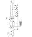
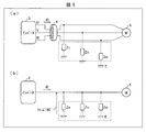
- FIG. 2 is a schematic system diagram illustrating a configuration example to which the leakage current calculation apparatus 1 according to the first embodiment of the present invention is applied.
- the leakage current calculation device 1 is configured to monitor a three-phase motor 5 (load) such as a servo motor driven by an inverter 3 that uses a commercial power system 2 as a power source.
- load such as a servo motor driven by an inverter 3 that uses a commercial power system 2 as a power source.
- the commercial power system 2 is a three-phase AC type AC power source in which the S phase is grounded to the ground E among different three phases (R phase, S phase, T phase). These three phases are respectively connected to the input side of the inverter 3 via R line, S line, and T line.
- the inverter 3 generates a predetermined control voltage from the three-phase power supplied from the commercial power system 2 and corresponds to the three phases (U phase, V phase, W phase) on the output side (U line, V line). , W line) to the three-phase motor 5 respectively.
- the three-phase motor 5 is connected to the output side of the inverter 3 and operates using each supplied control voltage.
- a zero-phase current transformer 4 surrounding the U line, the V line, and the W line is provided.
- the zero-phase current transformer 4 measures a three-phase synthesized ground zero-phase current I 0 that flows between the inverter 3 and the three-phase motor 5. As will be described in detail later, this zero-phase current I0 is equal to a leakage current flowing between the three-phase motor 5 and the ground E.
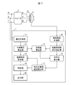
- FIG. 1 is a block diagram showing a main configuration of a leakage current calculation apparatus according to Embodiment 1 of the present invention.
- the leakage current calculation device 1 includes a voltage measurement unit 11, a leakage current measurement unit 12, a ground voltage calculation unit 13, a system frequency component extraction unit 14 (frequency component extraction unit), and a phase difference calculation unit 15 ( (Phase difference determination unit), circle center calculation unit 16, resistance leakage current calculation unit 17 (leakage current calculation unit), insulation resistance calculation unit 18, determination unit 19 (insulation degradation load identification unit, insulation degradation determination unit), and output
- the unit 20 is provided.
- the voltage measurement unit 11 measures at least one of the line voltages on the input side of the inverter 3. In this embodiment, the line voltage between the R phase and the S phase on the input side of the inverter 3 is measured.
- the line voltage to be measured is not limited to this, and may be any line voltage.
- the voltage measuring unit 11 may measure a voltage between the R phase and the T phase, or a voltage between the T phase and the S phase.
- the voltage measurement unit 11 may have a low-pass filter or a band-pass filter for removing high frequency components from the measured voltage or extracting system frequency components.
- the ground voltage calculation unit 13 calculates the ground voltage between the neutral point of the commercial power system 2 and the ground E from at least one of the line voltages measured by the voltage measurement unit 11. In the present embodiment, the ground voltage is calculated from the line voltage between RS.
- the leakage current measuring unit 12 measures a leakage current (zero-phase current) flowing between the three-phase motor 5 and the ground E through the zero-phase current transformer 4.
- the leakage current measuring unit 12 may have a low-pass filter or a band-pass filter for removing a high frequency component from the measured leakage current or extracting a system frequency component.
- the system frequency component extraction unit 14 extracts a leakage current component synchronized with the system frequency of the commercial power system 2 (that is, a leakage current component having the same frequency as the system frequency) from the measured leakage current.
- a leakage current component synchronized with the system frequency of the commercial power system 2 (that is, a leakage current component having the same frequency as the system frequency) from the measured leakage current.
- DFT Discrete Fourier Transform
- FFT Fast Fourier Transform
- the phase difference calculation unit 15 calculates the phase difference between the calculated ground voltage and the extracted leakage current component.
- the calculation of the phase difference is performed by, for example, arithmetic processing. Instead, the phase difference may be determined by measuring the phase difference using a predetermined measurement circuit.
- the circle center calculation unit 16 calculates the center point of the circle drawn by each point (specific point) specified by the leakage current component calculated at at least three different time points and the determined phase difference.
- the resistance component leakage current calculation unit 17 is a current that flows between the three-phase motor 5 and the ground E through the ground insulation resistance of the three-phase motor 5 (the ground insulation resistance component for the system frequency). Leakage current) is calculated.
- the insulation resistance calculation unit 18 calculates the ground insulation resistance of the three-phase motor 5 by using the ground insulation resistance leakage current corresponding to the calculated system frequency and the calculated ground voltage.
- the determination unit 19 determines the presence or absence of insulation failure (insulation deterioration) of the three-phase motor 5 based on the leakage current or the ground insulation resistance corresponding to the calculated ground frequency for the system frequency.
- the output unit 20 outputs the determination result of the insulation failure to the outside of the leakage current calculation device 1 in a desired form. This output is performed as, for example, screen display, communication output, or contact signal output.
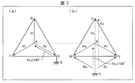
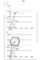
- FIG. 3 is a diagram for explaining the principle for calculating the ground voltage of the commercial power system 2 in Embodiment 1 of the present invention.
- the leakage current calculation apparatus 1 calculates a voltage (ground voltage) applied to the ground insulation resistance of the three-phase motor 5 in order to calculate the ground insulation resistance of the three-phase motor 5. This ground voltage calculation method will be described below with reference to FIG.
- the ground voltage applied to the ground insulation resistance of the three-phase motor 5 is equal to the voltage between the neutral point (N phase) of the commercial power system 2 and the ground E.
- the S phase (S line) is grounded as shown in FIG. Since the voltage of the S phase with respect to the neutral point is the system voltage Vs between the N phase and the S phase, the voltage between the N phase and the ground E is 180 ° in phase with the system voltage Vs. The voltage Vs is 180 °.
- the potential of the neutral point N of the inverter 3 is equal to the potential of the neutral point N of the commercial power system 2 as shown in FIG. Therefore, the voltage between the neutral point N of the inverter 3 and the ground E is also equal to the ground voltage Vs ⁇ 180 ° of the commercial power system 2.
- the U-phase ground voltage Eu is obtained by adding Vs ° 180 ° to the voltage Vu between the N-phase and the U-phase.
- the V-phase ground voltage Ev is obtained by adding Vs ⁇ 180 ° to the voltage Vv between the N-phase and the V-phase.
- the RS line voltage is a vector sum of the voltage Vr between the neutral point (N phase) and the R phase and the ground voltage Vs.
- the ground voltage calculation unit 13 can calculate the system voltage Vs of the commercial power system 2 by dividing the measured RS line voltage by ⁇ 3.
- the system voltage Vs and the ground voltage Vs ⁇ 180 ° are voltages whose effective values are equal to each other and whose phases are shifted from each other by 180 °. Therefore, the ground voltage calculation unit 13 can calculate the ground voltage Vs ⁇ 180 ° by shifting the phase of the calculated system voltage Vs by 180 °.
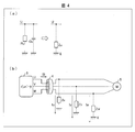
- FIG. 4 is a diagram for explaining a leakage current flowing between the three-phase motor 5 and the ground E in the first embodiment of the present invention.
- the ground insulation resistance and ground stray capacitance of the three-phase motor 5 are impedance components between the wiring or coil of the three-phase motor 5 and the ground E. These are connected in parallel to each other. Therefore, as shown in FIG. 4A, the ground insulation resistance Ru and the ground stray capacitance Cu between the U phase and the ground E on the output side of the inverter 3 are both between the U phase and the ground E. It is a component constituting the impedance Zu between them.
- ground insulation resistance Rv and the ground stray capacitance Cv between the V phase and the ground E are components that constitute the impedance Zv between the V phase and the ground E.
- ground insulation resistance Rw and the ground stray capacitance Cw between the W phase and the ground E are components that constitute the impedance Zw between the W phase and the ground E.
- leakage current flows through each phase on the output side of the inverter 3. Specifically, the leakage current Iu flows through the U phase, the leakage current Iv flows through the V phase, and the leakage current Iw flows through the W phase.
- the leakage current I0 As described above, the zero-phase current I 0 measured through the zero-phase current transformer 4 is equal to the leakage current flowing through the combined impedance of the three-phase motor 5. Therefore, in the following, the leakage current may be referred to as leakage current I0.
- FIG. 5 is a diagram illustrating the ground insulation resistance between the three-phase motor 5 and the ground E according to the first embodiment of the present invention.
- the ground voltage Vs ⁇ 180 ° is applied to each phase (U, V, W) on the output side of the inverter 3 in the same phase.
- the ground combined impedance Z0 includes the ground insulation resistance and the ground stray capacitance of the three-phase motor 5 connected in parallel with each other as components. Therefore, the current I0r flowing through the ground insulation resistance in Z0 is I0 ⁇ cos ⁇ , where ⁇ is the phase difference between the zero-phase current I0 and the ground voltage Vs ⁇ 180 °. On the other hand, the current I0c flowing through the ground stray capacitance in Z0 is I0 ⁇ sin ⁇ .
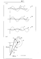
- FIG. 6 is a diagram for explaining the principle for the leakage current calculation apparatus 1 according to the first embodiment of the present invention to calculate the leakage current synchronized with the system frequency of the commercial power system 2.
- the leakage current I0 measured by the leakage current measuring unit 12 includes a component (I0_sys) synchronized with the system frequency of the commercial power system 2 and a component (I0_inv) synchronized with the operation frequency of the inverter 3.
- I0_sys a component synchronized with the system frequency of the commercial power system 2
- I0_inv a component synchronized with the operation frequency of the inverter 3.
- the frequency (system frequency) of the voltage that the commercial power system 2 supplies to the inverter 3 is 60 Hz
- the frequency (operation frequency) of the voltage that the inverter 3 drives the three-phase motor 5 is 50 Hz. is there. That is, both frequency settings are different from each other.
- the system frequency component extraction unit 14 extracts only the leakage current I0_sys of the system frequency component from the measured leakage current I0 by executing a calculation process that extracts a leakage current having the same frequency as the system frequency. . Since the system frequency and the operation frequency are different, in this extraction process, the component synchronized with the system frequency is extracted, but the component synchronized with the operation frequency is not extracted. Thereby, the extracted leakage current I0_sys does not include the leakage current I0_inv synchronized with the operation frequency component of the inverter 3.
- the impedance between the three-phase motor 5 and the ground E includes both ground insulation resistance and ground stray capacitance.
- the phase of the measured leakage current I0 is shifted from the phase of the ground voltage Vs ⁇ 180 ° due to the influence of the ground stray capacitance. . Therefore, the phase difference ⁇ of the leakage current I0_sys extracted from the leakage current I0 is also shifted from the phase of the ground voltage Vs ⁇ 180 °.
- the leakage current component extracted from the leakage current I0 includes only the leakage current I0_sys. Therefore, the phase difference ⁇ between the ground voltage VsV180 ° and the leakage current component (I0_sys itself) is always equal regardless of the time of measurement.
- a vector connecting the origin of the plane coordinate system and the point where the end point P0 is projected on the vertical axis of the plane coordinate system corresponds to the capacity leakage current I0C_sys of the system frequency component with high accuracy. That is, the value of this projection point is the effective value of I0C_sys.
- the leakage current calculation device 1 extracts a component synchronized with the system frequency from the measured leakage current I0.
- the leakage current I0_sys for the system frequency can be calculated with high accuracy.
- the ground insulation resistance of the three-phase motor 5 can be accurately calculated by using the ground voltage Vs ⁇ 180 ° and the leakage current I0R_sys.
- the end point when the leakage current I0 is expressed in vector is not fixed to one point, and the position changes at each measurement time point. .
- the leakage current extracted by the system frequency component extraction unit 14 includes both the leakage current I0_sys for the system frequency and the leakage current I0_inv for the operating frequency.
- the system frequency component extraction unit 14 cannot distinguish between the component synchronized with the system frequency included in the leakage current I0 and the component synchronized with the operation frequency. Therefore, when the system frequency component extraction unit 14 executes a process of extracting a component synchronized with the system frequency from the leakage current I0, as a result, the leakage current I0_sys synchronized with the system frequency and the leakage current I0_inv synchronized with the operation frequency are obtained. The mixed leakage current I0_mix is extracted.
- the vector drawn in the plane coordinate system is a composite vector (I0_mix vector) of the I0_sys vector and the I0_inv vector.
- I0_mix vector the position of the end point of this composite vector is determined at each measurement time point, such as point P1 (specific point), point P2 (specific point), and point P3 (specific point) due to the influence of I0_inv. Change. Specifically, as shown in FIG. 6B, this change occurs so that each end point draws a circle 61.
- the end point of the vector is not determined to be a single point. Therefore, the resistance leakage current I0R_sys of the system frequency component is accurately calculated based on this end point. I can't do it. In other words, even if I0R_sys is calculated based on the end point, the value fluctuates at each measurement time, and thus an accurate value cannot be specified.
- FIG. 7 is a diagram for explaining the principle of rotation of the end point when the extracted leakage current component is expressed in vector when the system frequency and the operation frequency match in Embodiment 1 of the present invention.
- the system frequency and the operating frequency are slightly different from each other even if they are set to the same value. For example, even when each is set to 60 Hz, the system frequency is 60.00 Hz, while the operating frequency is 60.01 Hz, so that there is a slight deviation from each other. Due to this frequency shift, as shown in FIG. 7A, the waveform 71 of I0_sys and the waveform 72 of I0_inv are slightly shifted from each other as the measurement time point gradually changes to P1, P2, and P3. go.
- the leakage current I0_mix extracted from the leakage current I0 includes the leakage current I0_sys for the system frequency and the leakage current I0_inv for the operation frequency.
- the determined phase difference ⁇ is a phase difference between the ground voltage Vs ⁇ 180 ° and the leakage current I0_mix
- a shift occurs between the waveform of I0_sys and the waveform of I0_inv included in the leakage current I0_inv.
- the value of the phase difference ⁇ shifts with time.
- the position of the end point when the leakage current I0_mix is expressed in vector also changes with time.
- the positions of the end points (specific points) P1 to P3 of the leakage current I0 change corresponding to the waveform shifts of P1 to P3 in FIG.
- the end point of I0_mix draws a circle 73 with time as shown in FIG. That is, P1 to P3 are plotted on the circle 73 in principle.
- the end point of I0_sys matches the center point 74 of the circle 73. Therefore, the leakage current calculation apparatus 1 according to the present embodiment calculates the center point 74 and further projects the center point 74 on the horizontal axis and the vertical axis of the plane coordinate axis, thereby calculating I0R_sys and I0C_inv with high accuracy.
- FIG. 8 is a diagram illustrating a first method for calculating a ground insulation resistance component leakage current according to the first embodiment of the present invention.
- the system frequency component extraction unit 14 extracts I0_mix at three different time points.
- the phase difference calculation unit 15 calculates the phase difference ⁇ at three different time points.
- the circle center calculation unit 16 calculates points P1 to P3 which are end points when each I0_mix is expressed in vector based on the leakage current I0_mix and the phase difference ⁇ determined at the three time points.
- the circle center calculation unit 16 calculates the outer center of the triangle 81 having these points as vertices instead of directly calculating the circle 82 passing through these points P1 to P3. This outer center coincides with the center point 83 of a circle 82 circumscribing the triangle 81. As described above, in the example of FIG. 8, the circle center calculation unit 16 can calculate the center point 83 of the circle 82 passing through these points by calculating the outer center of the triangle 81 having P1 to P3 as vertices. it can.
- the circle center calculation unit 16 outputs the calculated center point 83 to the resistance leakage current calculation unit 17.
- the vector having the origin of the plane coordinate system as the start point and the center point 83 as the end point is nothing but the leak current I0_sys for the system frequency in the leak current I0_mix extracted from the leak current I0. Therefore, the resistance component leakage current calculation unit 17 can calculate the leakage current I0R_sys corresponding to the ground insulation resistance out of the leakage current I0_sys corresponding to the system frequency by projecting the calculated center point 83 on the horizontal axis.
- the resistance leakage current calculation unit 17 outputs the calculated I0R_sys to the insulation resistance calculation unit 18.
- the insulation resistance calculator 18 calculates the ground insulation resistance of the three-phase motor 5 using the leakage current I0R_sys and the ground voltage Vs ⁇ 180 °.
- the center point 83 is calculated using only the three points P1 to P3. That is, in order to calculate I0R_sys, it suffices to measure the leakage current I0 at three different time points, so that I0R_sys can be calculated at high speed.
- FIG. 9 is a diagram illustrating a second method for calculating the ground insulation resistance leakage current according to the first embodiment of the present invention.
- the system frequency component extracting unit 14 extracts I0_mix at four or more different time points.
- the phase difference calculation unit 15 calculates the phase difference ⁇ at four or more different time points.
- the circle center calculation unit 16 calculates an equation of a circle 91 that passes through each of these points Pn. Then, using this equation, the center point 92 of the circle 91 is calculated. In the example of FIG. 9, the circle center calculation unit 16 calculates the equation of the circle 91 by the least square method of the circle using the calculated points Pn. More specific description will be given below.
- FIG. 10 is a diagram for explaining the least square method of a circle according to the first embodiment of the present invention.
- each point Pn is calculated as a point P1 (x1, y1), a point P2 (x2, y2), a point P3 (x3, y3), a point P4 (x4, y4),.
- the calculation of the leakage current I0_sys for the ground insulation resistance based on the center point 92 and the calculation of the ground insulation resistance of the three-phase motor 5 based on the leakage current I0_sys and the ground voltage Vs ⁇ 180 ° are the same as the above-described example.
- the center point 92 of the circle 91 can be calculated with higher accuracy. Therefore, the leakage current I0_sys and the ground insulation resistance can be calculated with higher accuracy.
- FIG. 9B shows an example of the actual calculation result of I0_sys.
- the center point 92 determined from this equation is projected on the horizontal axis, the value is 4.4 mA, and thus 4.4 mA is calculated as I0R_sys.
- the ground insulation resistance of the three-phase motor 5 calculated using 4.4 mA of I0_sys is 26.9 k ⁇ , which also agrees well with the theoretical value of 27 k ⁇ .
- FIG. 11 is a diagram for explaining a third method for calculating the ground insulation resistance leakage current according to the first embodiment of the present invention.
- the system frequency component extraction unit 14 does not directly calculate the center point of the circle, but instead, the minimum value of the leakage current corresponding to the ground insulation resistance at I0_mix and the I0_mix within a certain time. Among these, the maximum value of the leakage current corresponding to the ground insulation resistance is calculated, and an intermediate value thereof is calculated as I0R_sys.
- the system frequency component extraction unit 14 extracts I0_mix at each time point within a fixed time (preferably a long time of 60 seconds or more), that is, until a point equal to or more than one circle is calculated.
- the phase difference calculation unit 15 calculates the phase difference ⁇ at each time point until points equal to or more than one circle are calculated.
- the circle center calculation unit 16 does not calculate the center of the circle.
- the insulation resistance calculation unit 18 executes the calculation of I0R_mix at each time point over a long time (60 seconds or more).
- the value of I0R_mix coincides with the value on the horizontal axis at the point where the end point when I0_mix is expressed in vector is projected on the horizontal axis. Since the end point draws a circle as described above, a point obtained by projecting the end point on the horizontal axis is always in a line obtained by projecting the entire circle on the horizontal axis. Therefore, the calculated minimum value 111 and the maximum value 112 corresponding to the end of the line are naturally determined in the calculated I0R_mix.
- the intermediate value 113 between the minimum value 111 and the maximum value 112 corresponds to the center point of the circle. To do. As described above, the value obtained by projecting the center point of the circle on the horizontal axis corresponds to I0R_sys. Therefore, the resistance leakage current calculation unit 17 can calculate I0R_sys by calculating the intermediate value 113.
- I0R_sys can be obtained by simple calculation.
- FIG. 11B shows an example of the actual calculation result of I0R_sys by the third method.
- 4.3 mA was calculated as the intermediate value 113, that is, I0R_sys.
- the ground insulation resistance of the three-phase motor 5 calculated using I0R_sys of 4.3 mA is 27.1 k ⁇ , which is in good agreement with the theoretical value of 27 k ⁇ .
- Embodiment 2 With reference to FIG. 12 and FIG. 13, Embodiment 2 which concerns on this invention is demonstrated below. Each member common to Embodiment 1 described above is denoted by the same reference numeral, and detailed description thereof is omitted.
- FIG. 12 is a schematic system diagram illustrating a configuration example to which the leakage current calculation apparatus 1 according to the second embodiment of the present invention is applied.
- the configuration of the leakage current calculation device 1 is basically the same as that of the first embodiment.
- one leakage current calculation device 1 can monitor each of the plurality of three-phase motors 5a and 5b.
- the three-phase motors 5a and 5b are driven by inverters 3a and 3b, respectively.
- the input sides of the inverters 3a and 3b are both connected to the common commercial power system 2.
- the output side of the inverter 3a is connected to the three-phase motor 5a, while the output side of the inverter 3b is connected to the three-phase motor 5b.
- a zero-phase current transformer 4a is disposed between the inverter 3a and the three-phase motor 5a, while a zero-phase current transformer 4b is disposed between the inverter 3b and the three-phase motor 5b.
- These zero-phase current transformers 4 a and 4 b are both connected to the leakage current measuring unit 12 of the leakage current calculating device 1.
- the leakage current calculation device 1 calculates a ground insulation resistance leakage current and a ground insulation resistance corresponding to each of the three-phase motors 5a and 5b. The procedure will be described below.
- the voltage measuring unit 11 measures at least one of the line voltages on the input side of any one of the plurality of inverters 3a and 3b. Since the input sides of the inverters 3a and 3b are connected to the common commercial power system 2, for example, the voltage Rs between the R phase and the S phase of the inverter 3a is the voltage between the R phase and the S phase of the inverter 3b. Is exactly equal to Rs. As described above, in the present embodiment, the voltage Rs needs to be measured only at one place, so that the configuration of the leakage current calculation apparatus 1 can be further simplified.
- the ground voltage calculation unit 13 calculates the ground voltage Vs ⁇ 180 ° based on the voltage Rs measured from the input side of the inverter 3a. Since voltage Rs is common to inverters 3a and 3b, leakage current calculation device 1 uses voltage Vs ⁇ ⁇ 180 ° as a ground voltage common to three-phase motor 5a and three-phase motor 5b in the following processing.
- the leakage current measuring unit 12 measures the leakage current of the three-phase motor 5a through the zero-phase current transformer 4a, and measures the leakage current of the three-phase motor 5b through the zero-phase current transformer 4b. That is, the leakage current calculation device 1 includes one leakage current measuring unit 12 that is common to the three-phase motors 5a and 5b.
- the leakage current calculation device 1 may include a plurality of leakage current measuring units 12a and 12b corresponding to the three-phase motors 5a and 5b, respectively.
- the leakage current measuring unit 12a is connected to the zero-phase current transformer 4a
- the leakage current measuring unit 12b is connected to the zero-phase current transformer 4b.
- the leakage current measurement unit 12a measures the leakage current of the three-phase motor 5a through the zero-phase current transformer 4a
- the leakage current measurement unit 12b calculates the leakage current of the three-phase motor 5b through the zero-phase current transformer 4b. measure.
- the system frequency component extraction unit 14 extracts a leakage current component corresponding to the three-phase motor 5a from the leakage current of the three-phase motor 5a.
- a leakage current component corresponding to the three-phase motor 5b is extracted from the leakage current of the three-phase motor 5b.
- the phase difference calculation unit 15 calculates the phase difference between the calculated ground voltage and the leakage current component of the three-phase motor 5a. Furthermore, the phase difference between the calculated ground voltage and the leakage current component of the three-phase motor 5b is calculated.
- the resistance leakage current calculation unit 17 calculates a ground insulation resistance leakage current of the three-phase motor 5a based on the center point of the circle corresponding to the three-phase motor 5a. Further, the leakage current corresponding to the ground insulation resistance of the three-phase motor 5b is calculated based on the center point of the circle corresponding to the three-phase motor 5b.
- the insulation resistance calculation unit 18 calculates the ground insulation resistance of the three-phase motor 5a from the ground voltage Vs ⁇ 180 ° and the leakage current corresponding to the ground insulation resistance of the three-phase motor 5a. Further, the ground insulation resistance of the three-phase motor 5b is calculated from the ground voltage Vs ⁇ 180 ° and the leakage current corresponding to the ground insulation resistance of the three-phase motor 5b.
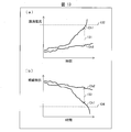
- FIG. 13 is a diagram illustrating an example of a temporal transition of the ground insulation resistance-divided leakage current or the calculated value of the ground insulation resistance for each of the three-phase motors 5 according to the second embodiment of the present invention.
- (A) of FIG. 13 shows the time transition of each earth insulation resistance part leakage current of each of the three-phase motors 5a and 5b.
- Ch1 corresponds to the three-phase motor 5a
- Ch2 corresponds to the three-phase motor 5b.
- FIG. 13B shows the temporal transition of the ground insulation resistance of each of the three-phase motors 5a and 5b.
- Ch1 corresponds to the three-phase motor 5a
- Ch2 corresponds to the three-phase motor 5b.
- the three-phase motors 5a and 5b have different temporal changes in the ground insulation resistance-divided leakage current or the ground insulation resistance, respectively.
- the leakage current calculation device 1 can appropriately identify the three-phase motor 5 that has undergone insulation degradation by comparing values with each other or by comparing each value with a predetermined threshold value.
- the determination unit 19 compares the ground insulation resistance leakage current corresponding to the system frequency of the three-phase motor 5a with the ground insulation resistance leakage current corresponding to the system frequency of the three-phase motor 5b.
- the degree of insulation deterioration in 5b can be determined respectively. For example, in the example of FIG. 13 (a), the ground insulation resistance leakage current corresponding to the system frequency of the three-phase motor 5a at a certain time and the ground insulation resistance leakage current corresponding to the system frequency of the three-phase motor 5b at the same time. A large degree of divergence 131 occurs between the two.
- the determination unit 19 detects the degree of divergence 131, the determination unit 19 determines that the three-phase motor 5 a having a larger leakage current with respect to the ground insulation resistance has deteriorated the insulation.
- the determination unit 19 can also identify the three-phase motor 5a in which the leakage current corresponding to the ground insulation resistance exceeds the specified threshold among the three-phase motors 5a and 5b as the three-phase motor 5a that has undergone insulation degradation. For example, in FIG. 13A, since the threshold current 132 is exceeded after a point in time when the leakage current for the ground insulation resistance of the three-phase motor 5a is present, the determination unit 19 causes the three-phase motor 5a to undergo insulation deterioration after this point. Can be identified.
- the determination using the above-described divergence or threshold value is performed not only on the ground insulation resistance component leakage current but also on the ground insulation resistances of the three-phase motors 5a and 5b as shown in FIG. 13B. be able to.
- a large degree of divergence 133 occurs between the ground insulation resistance of the three-phase motor 5a at a certain time point and the ground insulation resistance of the three-phase motor 5b at the same time point.
- the determination unit 19 determines that the three-phase motor 5a having a smaller ground insulation resistance is deteriorated in insulation.
- the determination unit 19 determines that the three-phase motor 5a has undergone insulation deterioration after this point. Can be specified.
- the leakage current calculation device 1 includes a plurality of leakage current measuring units 12, the leakage current measuring unit 12 for measuring the leakage current of the three-phase motor 5 that is not a monitoring target is not necessary.
- the leakage current calculation device 1 having such an unnecessary leakage current measurement unit 12 leads to a wasteful cost increase of the leakage current calculation device 1.
- each leakage current measuring unit 12 may be an extension unit for measuring the leakage current.
- a technique disclosed in Japanese Patent Application Laid-Open Publication No. 2013-181813 may be used.
- the leakage current calculation apparatus has an input side of an inverter whose power source is a three-phase AC commercial power system in which one of different three phases is grounded.
- a voltage measurement unit that measures at least one of the line voltages in the line, and a ground between the neutral point of the commercial power system and the ground from at least one of the line voltages measured by the voltage measurement unit
- a ground voltage calculation unit for calculating a voltage
- a leakage current measurement unit for measuring a leakage current flowing between the load connected to the output side of the inverter and the ground, and the commercial power system from the measured leakage current
- a frequency component extraction unit that extracts a leakage current component that is synchronized with the system frequency
- a phase difference determination unit that determines a phase difference between the calculated ground voltage and the extracted leakage current component, and The ground isolation of the load between the load and the ground based on the center point of the circle drawn by the specific points identified by the leakage current component extracted at three different time points and the determined phase difference
- a leakage current calculation unit for calculating a leakage current corresponding to the ground insulation resistance corresponding to the system frequency flowing through the resistor.
- the leakage current component extracted from the leakage current includes both the leakage current synchronized with the grid frequency and the leakage current synchronized with the operation frequency. ing. Since the frequencies of the two do not exactly match each other and are slightly shifted from each other, the phase difference between the ground voltage and the leakage current component is shifted from each other at each measurement time point. Therefore, the point defined by the leakage current component and the phase difference changes at each measurement time and draws a circle.
- the leakage current calculation device is based on the center point of a circle drawn by each specific point specified by the leakage current component extracted at the three different time points and the calculated phase difference, The leakage current corresponding to the ground insulation resistance corresponding to the system frequency flowing between the load and the ground through the ground insulation resistance of the load is calculated.
- the center point of this circle corresponds to the end point of the vector representing the leakage current corresponding to the system frequency included in the leakage current component. Therefore, the leakage current calculation device can accurately calculate the leakage current corresponding to the ground insulation resistance out of the leakage current corresponding to the system frequency based on the center point.
- the leakage current calculation apparatus when the system frequency of the commercial power system matches the operation frequency of the inverter device, the leakage current corresponding to the ground insulation resistance corresponding to the system frequency Can be calculated with high accuracy.
- a leakage current calculation device is the leakage current calculation apparatus according to aspect 1, wherein the leakage current is calculated on the output side of the inverter based on the calculated ground voltage and the calculated ground insulation resistance component leakage current corresponding to the system frequency.
- a ground insulation resistance calculation unit for calculating a ground insulation resistance of the load is further provided.
- the ground insulation resistance of the load can be calculated with higher accuracy.
- the leakage current calculation device is the leakage current calculation apparatus according to aspect 1 or 2, wherein the leakage current calculation unit is based on an equation of a circumscribed circle circumscribing a triangle defined by the three specific points. It is characterized by specifying the center point.
- the ground resistance leakage current corresponding to the system frequency can be calculated at higher speed.
- the leakage current calculation apparatus is characterized in that, in the aspect 1 or 2, the leakage current calculation unit specifies a center point of the circle based on a least square method of the circle.
- the ground resistance leakage current corresponding to the system frequency can be calculated with higher accuracy.
- the leakage current calculation apparatus is the leakage current calculation device according to Aspect 1 or 2, wherein the leakage current calculation unit is configured to extract the leakage current component extracted at each time point within a predetermined time and the determined phase difference. Based on the calculated values, the ground insulation resistance leakage current at each time point is calculated, and the intermediate value between the maximum and minimum values is calculated as the ground insulation resistance leakage current for the system frequency. It is characterized by doing.
- each of the plurality of loads is individually connected to the output side of each of the plurality of inverters.
- Each of the input sides is connected to the same commercial power system, and the voltage measurement unit measures at least one of the line voltages on the input side of any of the plurality of inverters,
- the leakage current measurement unit measures a plurality of leakage currents corresponding to each of the plurality of loads, and the frequency component extraction unit applies each of the plurality of measured leakage currents to each of the plurality of loads.
- a plurality of phase differences, and the leakage current calculation unit is configured to ground isolation for a plurality of system frequencies corresponding to each of the loads based on center points of the plurality of circles corresponding to the plurality of loads. It is characterized by calculating a resistance leakage current.
- the ground resistance component leakage current corresponding to the system frequency of a plurality of different loads can be calculated by one leakage current calculation device. Moreover, since the voltage measurement by the voltage measurement unit may be performed at any one of the plurality of inverters, the voltage can be measured only at one place. Thereby, the configuration of the leakage current calculation device can be further simplified.
- the leakage current calculation apparatus is the leakage current calculation apparatus according to Aspect 6, in which the load having a leakage current corresponding to the ground insulation resistance corresponding to the system frequency exceeds a predetermined threshold among the plurality of loads.
- An insulation degradation load identifying unit that identifies the degraded load is further provided.
- the leakage current calculation apparatus compares the ground insulation resistance leakage currents corresponding to the plurality of system frequencies with each other to thereby determine the degree of insulation deterioration in the plurality of loads. It further comprises an insulation deterioration determining unit for determining each.
- a leakage current calculation method is provided on the input side of an inverter that uses a three-phase AC commercial power system that is grounded as one of three different phases.
- a voltage measurement step for measuring at least one of the line voltages in the line, and a ground voltage for calculating a ground voltage between the neutral point of the commercial power system and the ground from the measured line voltage
- a voltage calculation step for measuring a leakage current flowing between the load connected to the output side of the inverter and the ground, and a system frequency of the commercial power system from the measured leakage current
Landscapes
- Physics & Mathematics (AREA)
- General Physics & Mathematics (AREA)
- Nonlinear Science (AREA)
- Mathematical Physics (AREA)
- Engineering & Computer Science (AREA)
- Power Engineering (AREA)
- Testing Of Short-Circuits, Discontinuities, Leakage, Or Incorrect Line Connections (AREA)
- Tests Of Circuit Breakers, Generators, And Electric Motors (AREA)
- Emergency Protection Circuit Devices (AREA)
- Measurement Of Current Or Voltage (AREA)
Abstract
A leakage-current resistance portion calculation unit (17) calculates, on the basis of the center point of a circle drawn using each specific point specified by leakage current components extracted from at least three different points in time and a calculated phase difference, the insulation-to-ground resistance portion of the system-frequency portion of the leakage current of a commercial power system (2) that flows between a three-phase motor (5) and a ground (E) through the resistance of the insulation to ground of the three-phase motor (5). As a result, the insulation-to-ground resistance portion of the system-frequency portion of the leakage current of a commercial power system is calculated with a high degree of accuracy when the system frequency of the commercial power system and the operating frequency of an inverter match.
Description
本発明は、漏洩電流を算出する漏洩電流算出装置および漏洩電流算出方法に関する。
The present invention relates to a leakage current calculation device and a leakage current calculation method for calculating leakage current.
三相モーターなどの負荷における漏洩電流を算出する技術の一例として、特許文献1に、基本交流周波数波形のゼロクロス間に対応する期間において周波数帯域の零相電流成分を積分することにより、対地漏洩電流のうちの、三相モーターの対地容量成分を除く対地絶縁抵抗成分を通じて流れる漏洩電流値を算出する漏洩電流算出装置が開示されている。
As an example of a technique for calculating a leakage current in a load such as a three-phase motor, Patent Document 1 discloses a ground leakage current by integrating a zero-phase current component in a frequency band in a period corresponding to a zero crossing of a basic AC frequency waveform. Among them, a leakage current calculation device for calculating a leakage current value flowing through a ground insulation resistance component excluding a ground capacitance component of a three-phase motor is disclosed.
特許文献1の漏洩電流算出装置は、商用電力系統の周波数と、インバータ機器の運転周波数との設定が異なる場合は、対地絶縁抵抗成分を通じて流れる漏洩電流を精度良く算出することができる。しかし、商用電力系統の周波数と、インバータ機器の運転周波数との設定が一致する場合は、算出される漏洩電流に誤差が生じる恐れがある。
The leakage current calculation device of Patent Document 1 can accurately calculate the leakage current flowing through the ground insulation resistance component when the setting of the frequency of the commercial power system and the operation frequency of the inverter device are different. However, when the setting of the frequency of the commercial power system matches the operating frequency of the inverter device, an error may occur in the calculated leakage current.
本発明は前記の課題を解決するためになされたものである。そして、その目的は、商用電力系統の系統周波数と、インバータ機器の運転周波数とが一致する場合に系統周波数分の対地絶縁抵抗分漏洩電流を精度良く算出することができる漏洩電流算出装置および漏洩電流算出方法を提供することにある。
The present invention has been made to solve the above-described problems. And the purpose is that the leakage current calculation device and the leakage current that can accurately calculate the leakage current to the ground insulation resistance for the system frequency when the system frequency of the commercial power system and the operation frequency of the inverter equipment match It is to provide a calculation method.
本発明の一態様に係る漏洩電流算出装置は、前記の課題を解決するために、異なる三相のうちいずれかが接地されている三相交流式の商用電力系統を電源とするインバータの入力側における線間電圧のうち少なくともいずれかを計測する電圧計測部と、前記電圧計測部によって計測された少なくともいずれかの前記線間電圧から、前記商用電力系統の中性点と大地との間の対地電圧を算出する対地電圧算出部と、前記インバータの出力側に接続される負荷と前記大地との間を流れる漏洩電流を計測する漏洩電流計測部と、計測された前記漏洩電流から、前記商用電力系統の系統周波数に同期する漏洩電流成分を抽出する周波数成分抽出部と、算出された前記対地電圧と、抽出された前記漏洩電流成分との位相差を決定する位相差決定部と、少なくとも3つの異なる時点において抽出された前記漏洩電流成分および決定された前記位相差によって特定される各特定点が描く円の中心点に基づき、前記負荷と前記大地との間を前記負荷の対地絶縁抵抗を通じて流れる前記系統周波数分の対地絶縁抵抗分漏洩電流を算出する漏洩電流算出部とを備えていることを特徴としている。
In order to solve the above-described problem, a leakage current calculation apparatus according to an aspect of the present invention is provided on the input side of an inverter that uses a three-phase AC commercial power system that is grounded as one of three different phases. A voltage measurement unit that measures at least one of the line voltages in the line, and a ground between the neutral point of the commercial power system and the ground from at least one of the line voltages measured by the voltage measurement unit A ground voltage calculation unit that calculates a voltage, a leakage current measurement unit that measures a leakage current flowing between the load connected to the output side of the inverter and the ground, and the commercial power from the measured leakage current A frequency component extraction unit that extracts a leakage current component synchronized with the system frequency of the system, a phase difference determination unit that determines a phase difference between the calculated ground voltage and the extracted leakage current component; Based on the center point of a circle drawn by each specific point specified by the leakage current component extracted at three different time points and the determined phase difference, the load is grounded between the load and the ground. And a leakage current calculation unit for calculating a leakage current corresponding to the ground insulation resistance corresponding to the system frequency flowing through the insulation resistance.
本発明の一態様に係る漏洩電流算出方法は、前記の課題を解決するために、異なる三相のうちいずれかが接地されている三相交流式の商用電力系統を電源とするインバータの入力側における線間電圧のうち少なくともいずれかを計測する電圧計測工程と、計測された前記少なくともいずれかの線間電圧から、前記商用電力系統の中性点と大地との間の対地電圧を算出する対地電圧算出工程と、前記インバータの出力側に接続される負荷と、前記大地との間を流れる漏洩電流を計測する漏洩電流計測工程と、計測された前記漏洩電流から、前記商用電力系統の系統周波数に同期する漏洩電流成分を抽出する周波数成分抽出工程と、算出された前記対地電圧と、決定された前記漏洩電流成分との位相差を決定する位相差決定工程と、少なくとも3つの異なる時点において抽出された前記漏洩電流成分および決定された前記位相差によって特定される各特定点が描く円の中心点に基づき、前記負荷と前記大地との間を前記負荷の対地絶縁抵抗を通じて流れる前記系統周波数分の前記対地絶縁抵抗分漏洩電流を算出する漏洩電流算出工程とを有することを特徴としている。
In order to solve the above-described problem, a leakage current calculation method according to an aspect of the present invention is provided on the input side of an inverter that uses a three-phase AC commercial power system that is grounded as one of three different phases. A voltage measurement step for measuring at least one of the line voltages in the line, and a ground voltage for calculating a ground voltage between the neutral point of the commercial power system and the ground from the measured line voltage A voltage calculation step, a leakage current measurement step for measuring a leakage current flowing between the load connected to the output side of the inverter and the ground, and a system frequency of the commercial power system from the measured leakage current A frequency component extraction step of extracting a leakage current component synchronized with the phase difference determination step of determining a phase difference between the calculated ground voltage and the determined leakage current component, and at least Based on the center point of a circle drawn by each of the specific points specified by the leakage current component extracted at two different time points and the determined phase difference, the load and the ground are connected to each other through the ground insulation resistance of the load. A leakage current calculating step of calculating a leakage current corresponding to the ground insulation resistance corresponding to the flowing system frequency.
本発明によれば、商用電力系統の系統周波数と、インバータ機器の運転周波数とが一致する場合に、系統周波数分の対地絶縁抵抗分漏洩電流を精度良く算出することができる。
According to the present invention, when the system frequency of the commercial power system matches the operating frequency of the inverter device, it is possible to accurately calculate the ground insulation resistance component leakage current for the system frequency.
〔実施形態1〕
図1~図11を参照して、本発明に係る実施形態1について以下に説明する。Embodiment 1
Embodiment 1 according to the present invention will be described below with reference to FIGS.
図1~図11を参照して、本発明に係る実施形態1について以下に説明する。
(構成例)
図2は、本発明の実施形態1に係る漏洩電流算出装置1を適用した構成例を示す概略系統図である。この図に示す例では、漏洩電流算出装置1は、商用電力系統2を電源とするインバータ3によって駆動されるサーボモーターなどの三相モーター5(負荷)を監視するように構成されている。 (Configuration example)
FIG. 2 is a schematic system diagram illustrating a configuration example to which the leakagecurrent calculation apparatus 1 according to the first embodiment of the present invention is applied. In the example shown in this figure, the leakage current calculation device 1 is configured to monitor a three-phase motor 5 (load) such as a servo motor driven by an inverter 3 that uses a commercial power system 2 as a power source.
図2は、本発明の実施形態1に係る漏洩電流算出装置1を適用した構成例を示す概略系統図である。この図に示す例では、漏洩電流算出装置1は、商用電力系統2を電源とするインバータ3によって駆動されるサーボモーターなどの三相モーター5(負荷)を監視するように構成されている。 (Configuration example)
FIG. 2 is a schematic system diagram illustrating a configuration example to which the leakage
商用電力系統2は、異なる三相(R相、S相、T相)のうちS相が大地Eに接地されている三相交流式の交流電源である。これらの三相は、R線、S線、およびT線を介して、インバータ3の入力側にそれぞれ接続されている。
The commercial power system 2 is a three-phase AC type AC power source in which the S phase is grounded to the ground E among different three phases (R phase, S phase, T phase). These three phases are respectively connected to the input side of the inverter 3 via R line, S line, and T line.
インバータ3は、商用電力系統2から供給される三相の電力から所定の制御電圧を生成し、出力側の三相(U相、V相、W相)に対応する三線(U線、V線、W線)を通じてそれぞれ三相モーター5に対して出力する。三相モーター5はインバータ3の出力側に接続されており、供給された各制御電圧を用いて動作する。
The inverter 3 generates a predetermined control voltage from the three-phase power supplied from the commercial power system 2 and corresponds to the three phases (U phase, V phase, W phase) on the output side (U line, V line). , W line) to the three-phase motor 5 respectively. The three-phase motor 5 is connected to the output side of the inverter 3 and operates using each supplied control voltage.
インバータ3と三相モーター5との間には、U線、V線、およびW線を取り囲む零相変流器4が設けられている。零相変流器4は、インバータ3と三相モーター5との間を流れる三相の合成された対地零相電流I0を計測する。詳しくは後述するが、この零相電流I0は、三相モーター5と大地Eとの間を流れる漏洩電流に等しい。
Between the inverter 3 and the three-phase motor 5, a zero-phase current transformer 4 surrounding the U line, the V line, and the W line is provided. The zero-phase current transformer 4 measures a three-phase synthesized ground zero-phase current I 0 that flows between the inverter 3 and the three-phase motor 5. As will be described in detail later, this zero-phase current I0 is equal to a leakage current flowing between the three-phase motor 5 and the ground E.
(漏洩電流算出装置1の構成)
図1は、本発明の実施形態1に係る漏洩電流算出装置の要部構成を示すブロック図である。この図に示すように、漏洩電流算出装置1は、電圧計測部11、漏洩電流計測部12、対地電圧算出部13、系統周波数成分抽出部14(周波数成分抽出部)、位相差算出部15(位相差決定部)、円中心算出部16、抵抗分漏洩電流算出部17(漏洩電流算出部)、絶縁抵抗算出部18、判定部19(絶縁劣化負荷特定部、絶縁劣化判定部)、および出力部20を備えている。 (Configuration of Leakage Current Calculation Device 1)
FIG. 1 is a block diagram showing a main configuration of a leakage current calculation apparatus according toEmbodiment 1 of the present invention. As shown in this figure, the leakage current calculation device 1 includes a voltage measurement unit 11, a leakage current measurement unit 12, a ground voltage calculation unit 13, a system frequency component extraction unit 14 (frequency component extraction unit), and a phase difference calculation unit 15 ( (Phase difference determination unit), circle center calculation unit 16, resistance leakage current calculation unit 17 (leakage current calculation unit), insulation resistance calculation unit 18, determination unit 19 (insulation degradation load identification unit, insulation degradation determination unit), and output The unit 20 is provided.
図1は、本発明の実施形態1に係る漏洩電流算出装置の要部構成を示すブロック図である。この図に示すように、漏洩電流算出装置1は、電圧計測部11、漏洩電流計測部12、対地電圧算出部13、系統周波数成分抽出部14(周波数成分抽出部)、位相差算出部15(位相差決定部)、円中心算出部16、抵抗分漏洩電流算出部17(漏洩電流算出部)、絶縁抵抗算出部18、判定部19(絶縁劣化負荷特定部、絶縁劣化判定部)、および出力部20を備えている。 (Configuration of Leakage Current Calculation Device 1)
FIG. 1 is a block diagram showing a main configuration of a leakage current calculation apparatus according to
電圧計測部11は、インバータ3の入力側における線間電圧のうち少なくともいずれかを計測する。本実施形態では、インバータ3の入力側におけるR相とS相との間の線間電圧が計測される。なお、計測対象の線間電圧はこれに限らず、任意の線間電圧であれば良い。たとえば電圧計測部11は、R相とT相との間の電圧、または、T相とS相との間の電圧を計測しても良い。なお、電圧計測部11は、計測した電圧から高周波数成分を除去したり系統周波数成分を抽出したりするためのローパスフィルタまたはバンドパスフィルタを有していても良い。
The voltage measurement unit 11 measures at least one of the line voltages on the input side of the inverter 3. In this embodiment, the line voltage between the R phase and the S phase on the input side of the inverter 3 is measured. The line voltage to be measured is not limited to this, and may be any line voltage. For example, the voltage measuring unit 11 may measure a voltage between the R phase and the T phase, or a voltage between the T phase and the S phase. The voltage measurement unit 11 may have a low-pass filter or a band-pass filter for removing high frequency components from the measured voltage or extracting system frequency components.
対地電圧算出部13は、電圧計測部11によって計測された線間電圧のうち少なくともいずれかから、商用電力系統2の中性点と大地Eと間の対地電圧を算出する。本実施形態では、R-S間の線間電圧から対地電圧が算出される。
The ground voltage calculation unit 13 calculates the ground voltage between the neutral point of the commercial power system 2 and the ground E from at least one of the line voltages measured by the voltage measurement unit 11. In the present embodiment, the ground voltage is calculated from the line voltage between RS.
漏洩電流計測部12は、三相モーター5と大地Eとの間を流れる漏洩電流(零相電流)を、零相変流器4を通じて計測する。漏洩電流計測部12は、計測された漏洩電流から高周波数成分を除去したり系統周波数成分を抽出したりするためのローパスフィルタまたはバンドパスフィルタを有していても良い。
The leakage current measuring unit 12 measures a leakage current (zero-phase current) flowing between the three-phase motor 5 and the ground E through the zero-phase current transformer 4. The leakage current measuring unit 12 may have a low-pass filter or a band-pass filter for removing a high frequency component from the measured leakage current or extracting a system frequency component.
系統周波数成分抽出部14は、計測された漏洩電流から、商用電力系統2の系統周波数に同期する漏洩電流成分(すなわち系統周波数と同一の周波数の漏洩電流成分)を抽出する。この抽出処理には、たとえばDFT(Discrete Fourier Transform)またはFFT(Fast Fourier Transform)などを用いても良い。
The system frequency component extraction unit 14 extracts a leakage current component synchronized with the system frequency of the commercial power system 2 (that is, a leakage current component having the same frequency as the system frequency) from the measured leakage current. For this extraction processing, for example, DFT (Discrete Fourier Transform) or FFT (Fast Fourier Transform) may be used.
位相差算出部15は、算出された対地電圧と、抽出された漏洩電流成分との位相差を算出する。位相差の算出はたとえば演算処理によって行われるが、その代わりに、所定の計測回路を用いて位相差を計測することによって位相差を決定しても良い。
The phase difference calculation unit 15 calculates the phase difference between the calculated ground voltage and the extracted leakage current component. The calculation of the phase difference is performed by, for example, arithmetic processing. Instead, the phase difference may be determined by measuring the phase difference using a predetermined measurement circuit.
円中心算出部16は、少なくとも3つの異なる時点において算出された漏洩電流成分および決定された位相差によって特定される各点(特定点)が描く円の中心点を算出する。
The circle center calculation unit 16 calculates the center point of the circle drawn by each point (specific point) specified by the leakage current component calculated at at least three different time points and the determined phase difference.
抵抗分漏洩電流算出部17は、算出された円の中心点に基づき、三相モーター5と大地Eとの間を三相モーター5の対地絶縁抵抗を通じて流れる電流(系統周波数分の対地絶縁抵抗分漏洩電流)を算出する。
Based on the calculated center point of the circle, the resistance component leakage current calculation unit 17 is a current that flows between the three-phase motor 5 and the ground E through the ground insulation resistance of the three-phase motor 5 (the ground insulation resistance component for the system frequency). Leakage current) is calculated.
絶縁抵抗算出部18は、算出された系統周波数分の対地絶縁抵抗分漏洩電流と、算出された対地電圧とを用いて、三相モーター5の対地絶縁抵抗を算出する。
The insulation resistance calculation unit 18 calculates the ground insulation resistance of the three-phase motor 5 by using the ground insulation resistance leakage current corresponding to the calculated system frequency and the calculated ground voltage.
判定部19は、算出された系統周波数分の対地絶縁抵抗分漏洩電流または対地絶縁抵抗に基づき、三相モーター5の絶縁不良(絶縁劣化)の有無を判定する。
The determination unit 19 determines the presence or absence of insulation failure (insulation deterioration) of the three-phase motor 5 based on the leakage current or the ground insulation resistance corresponding to the calculated ground frequency for the system frequency.
出力部20は、絶縁不良の判定結果を、所望の形態で漏洩電流算出装置1の外部に出力する。この出力は、たとえば画面表示、通信出力、または接点信号出力として行われる。
The output unit 20 outputs the determination result of the insulation failure to the outside of the leakage current calculation device 1 in a desired form. This output is performed as, for example, screen display, communication output, or contact signal output.
(対地電圧の算出)
図3は、本発明の実施形態1における商用電力系統2の対地電圧を算出するための原理を説明する図である。本実施形態の漏洩電流算出装置1は、三相モーター5の対地絶縁抵抗を算出するために、三相モーター5の対地絶縁抵抗にかかる電圧(対地電圧)を算出する。この対地電圧の算出方法について、図3を参照して以下に説明する。 (Calculation of ground voltage)
FIG. 3 is a diagram for explaining the principle for calculating the ground voltage of thecommercial power system 2 in Embodiment 1 of the present invention. The leakage current calculation apparatus 1 according to the present embodiment calculates a voltage (ground voltage) applied to the ground insulation resistance of the three-phase motor 5 in order to calculate the ground insulation resistance of the three-phase motor 5. This ground voltage calculation method will be described below with reference to FIG.
図3は、本発明の実施形態1における商用電力系統2の対地電圧を算出するための原理を説明する図である。本実施形態の漏洩電流算出装置1は、三相モーター5の対地絶縁抵抗を算出するために、三相モーター5の対地絶縁抵抗にかかる電圧(対地電圧)を算出する。この対地電圧の算出方法について、図3を参照して以下に説明する。 (Calculation of ground voltage)
FIG. 3 is a diagram for explaining the principle for calculating the ground voltage of the
三相モーター5の対地絶縁抵抗にかかる対地電圧は、商用電力系統2の中性点(N相)と、大地Eとの間の電圧に等しい。商用電力系統2では、図3の(a)に示すように、S相(S線)が接地されている。中性点を基準にしたS相の電圧は、N相とS相との間の系統電圧Vsであるため、N相と大地Eとの間の電圧は、系統電圧Vsと位相が180°反転した電圧Vs∠180°である。
The ground voltage applied to the ground insulation resistance of the three-phase motor 5 is equal to the voltage between the neutral point (N phase) of the commercial power system 2 and the ground E. In the commercial power system 2, the S phase (S line) is grounded as shown in FIG. Since the voltage of the S phase with respect to the neutral point is the system voltage Vs between the N phase and the S phase, the voltage between the N phase and the ground E is 180 ° in phase with the system voltage Vs. The voltage Vs is 180 °.
一方、図3の(b)に示すように、インバータ3の中性点Nの電位は、商用電力系統2の中性点Nの電位に等しい。そのため、インバータ3の中性点Nと、大地Eとの間の電圧も、商用電力系統2の対地電圧Vs∠180°に等しい。また、図3の(b)に示すように、U相の対地電圧Euは、N相とU相との間の電圧Vuに、Vs∠180°を加えたものである。V相の対地電圧Evは、N相とV相との間の電圧Vvに、Vs∠180°を加えたものである。W相の対地電圧Ewは、N相とW相との間の電圧Vwに、Vs∠180°を加えたものである。すなわち、Eu=Vu+Vs∠180°、Ev=Vv+Vs∠180°、およびEw=Vw+Vs∠180°である。
On the other hand, the potential of the neutral point N of the inverter 3 is equal to the potential of the neutral point N of the commercial power system 2 as shown in FIG. Therefore, the voltage between the neutral point N of the inverter 3 and the ground E is also equal to the ground voltage Vs∠180 ° of the commercial power system 2. Further, as shown in FIG. 3B, the U-phase ground voltage Eu is obtained by adding Vs ° 180 ° to the voltage Vu between the N-phase and the U-phase. The V-phase ground voltage Ev is obtained by adding Vs∠180 ° to the voltage Vv between the N-phase and the V-phase. The W-phase ground voltage Ew is obtained by adding Vs∠180 ° to the voltage Vw between the N-phase and the W-phase. That is, Eu = Vu + Vs∠180 °, Ev = Vv + Vs∠180 °, and Ew = Vw + Vs∠180 °.
ここで、U相の電圧Vu、V相の電圧Vv、およびW相の電圧Vwは、互いに位相が120°ずれているので、各相の電圧をすべて合算するとゼロになる特性を有している。すなわち、Vu+Vv+Vw=0である。そのため、電圧Vs∠180°が、三相モーター5の対地絶縁抵抗にかかる、商用電力系統2の系統周波数分の対地電圧である。
Here, the U-phase voltage Vu, the V-phase voltage Vv, and the W-phase voltage Vw are out of phase with each other by 120 °. . That is, Vu + Vv + Vw = 0. Therefore, the voltage Vs∠180 ° is a ground voltage corresponding to the system frequency of the commercial power system 2 applied to the ground insulation resistance of the three-phase motor 5.
図3の(a)に示すように、R-S線間電圧は、中性点(N相)とR相との間の電圧Vrと、対地電圧Vsとのベクトル和である。対地電圧算出部13は、計測されたR-S線間電圧を√3で除算することによって、商用電力系統2の系統電圧Vsを算出することができる。系統電圧Vsと、対地電圧Vs∠180°とは、互いに実効値が等しく、かつ、互いに位相が180°ずれた電圧である。そのため対地電圧算出部13は、算出された系統電圧Vsの位相を180°ずらすことによって、対地電圧Vs∠180°を算出することができる。
As shown in FIG. 3A, the RS line voltage is a vector sum of the voltage Vr between the neutral point (N phase) and the R phase and the ground voltage Vs. The ground voltage calculation unit 13 can calculate the system voltage Vs of the commercial power system 2 by dividing the measured RS line voltage by √3. The system voltage Vs and the ground voltage Vs∠180 ° are voltages whose effective values are equal to each other and whose phases are shifted from each other by 180 °. Therefore, the ground voltage calculation unit 13 can calculate the ground voltage Vs∠180 ° by shifting the phase of the calculated system voltage Vs by 180 °.
(漏洩電流)
図4は、本発明の実施形態1における三相モーター5と大地Eとの間を流れる漏洩電流を説明する図である。 (Leakage current)
FIG. 4 is a diagram for explaining a leakage current flowing between the three-phase motor 5 and the ground E in the first embodiment of the present invention.
図4は、本発明の実施形態1における三相モーター5と大地Eとの間を流れる漏洩電流を説明する図である。 (Leakage current)
FIG. 4 is a diagram for explaining a leakage current flowing between the three-
三相モーター5の対地絶縁抵抗および対地浮遊容量は、三相モーター5の配線またはコイルと大地Eとの間にあるインピーダンス成分である。これらは互いに並列接続されている関係にある。したがって、図4の(a)に示すように、インバータ3の出力側におけるU相と大地Eとの間にある対地絶縁抵抗Ruおよび対地浮遊容量Cuは、いずれも、U相と大地Eとの間にあるインピーダンスZuを構成する成分である。
The ground insulation resistance and ground stray capacitance of the three-phase motor 5 are impedance components between the wiring or coil of the three-phase motor 5 and the ground E. These are connected in parallel to each other. Therefore, as shown in FIG. 4A, the ground insulation resistance Ru and the ground stray capacitance Cu between the U phase and the ground E on the output side of the inverter 3 are both between the U phase and the ground E. It is a component constituting the impedance Zu between them.
同様に、V相と大地Eとの間にある対地絶縁抵抗Rvおよび対地浮遊容量Cvは、いずれも、V相と大地Eとの間にあるインピーダンスZvを構成する成分である。また、W相と大地Eとの間にある対地絶縁抵抗Rwおよび対地浮遊容量Cwは、いずれも、W相と大地Eとの間にあるインピーダンスZwを構成する成分である。
Similarly, the ground insulation resistance Rv and the ground stray capacitance Cv between the V phase and the ground E are components that constitute the impedance Zv between the V phase and the ground E. Also, the ground insulation resistance Rw and the ground stray capacitance Cw between the W phase and the ground E are components that constitute the impedance Zw between the W phase and the ground E.
図4の(b)に示すように、インバータ3の出力側において、各相を通ってそれぞれ漏洩電流が流れる。具体的には、U相を通って漏洩電流Iuが流れ、V相を通って漏洩電流Ivが流れ、W相を通って漏洩電流Iwが流れる。インバータ3の出力側を流れる零相電流I0は、各相の漏洩電流の総和に等しい。したがって、I0=Iu+Iv+Iwである。
As shown in FIG. 4 (b), leakage current flows through each phase on the output side of the inverter 3. Specifically, the leakage current Iu flows through the U phase, the leakage current Iv flows through the V phase, and the leakage current Iw flows through the W phase. The zero-phase current I0 flowing through the output side of the inverter 3 is equal to the sum of the leakage currents of the respective phases. Therefore, I0 = Iu + Iv + Iw.
系統周波数成分に着目すると、インバータ3の出力側における各相(U、V、W)には対地電圧Vs∠180°が同位相にかかる。そのため、Iu=Vs∠180°÷Zu、Iv=Vs∠180°÷Zu、Iv=Vs∠180°÷Zuである。したがって、I0=Vs∠180°÷(1÷Zu+1÷Zv+1÷Zw)である。
Paying attention to the system frequency component, the ground voltage Vs∠180 ° is applied to each phase (U, V, W) on the output side of the inverter 3 in the same phase. Therefore, Iu = Vs∠180 ° ÷ Zu, Iv = Vs∠180 ° ÷ Zu, and Iv = Vs∠180 ° ÷ Zu. Therefore, I0 = Vs∠180 ° ÷ (1 ÷ Zu + 1 ÷ Zv + 1 ÷ Zw).
以上のように、零相変流器4を通じて計測される零相電流I0は、三相モーター5の合成インピーダンスを通じて流れる漏洩電流に等しい。そのため以下では、漏洩電流を漏洩電流I0と表記する場合もある。
As described above, the zero-phase current I 0 measured through the zero-phase current transformer 4 is equal to the leakage current flowing through the combined impedance of the three-phase motor 5. Therefore, in the following, the leakage current may be referred to as leakage current I0.
(対地絶縁抵抗)
図5は、本発明の実施形態1における三相モーター5と大地Eとの間の対地絶縁抵抗を説明する図である。 (Ground insulation resistance)
FIG. 5 is a diagram illustrating the ground insulation resistance between the three-phase motor 5 and the ground E according to the first embodiment of the present invention.
図5は、本発明の実施形態1における三相モーター5と大地Eとの間の対地絶縁抵抗を説明する図である。 (Ground insulation resistance)
FIG. 5 is a diagram illustrating the ground insulation resistance between the three-
系統周波数成分に着目すると、インバータ3の出力側における各相(U、V、W)には対地電圧Vs∠180°が同位相にかかる。このことは、対地電圧Vs∠180°がかかる共通の母線にZu、Zv、およびZwが並列接続されていることに等しいと見なせる。そのため、三相モーター5と大地Eとの間の合成インピーダンスをZ0とすると、1÷Z0=1÷Zu+1÷Zv+1÷Zwである。この式を変形するとI0=Vs∠180°÷Z0となり、したがってZ0=Vs∠180°÷I0である。
Paying attention to the system frequency component, the ground voltage Vs∠180 ° is applied to each phase (U, V, W) on the output side of the inverter 3 in the same phase. This can be regarded as being equivalent to Zu, Zv, and Zw being connected in parallel to a common bus with a ground voltage Vs of 180 °. Therefore, if the combined impedance between the three-phase motor 5 and the ground E is Z0, 1 ÷ Z0 = 1 ÷ Zu + 1 ÷ Zv + 1 ÷ Zw. If this equation is modified, I0 = Vs∠180 ° ÷ Z0, and therefore Z0 = Vs∠180 ° ÷ I0.
対地合成インピーダンスZ0は、互いに並列接続される三相モーター5の対地絶縁抵抗および対地浮遊容量を、それぞれ成分として含んでいる。そのため、Z0のうち対地絶縁抵抗を通じて流れる電流I0rは、零相電流I0と対地電圧Vs∠180°との位相差をθとすると、I0×cosθである。一方、Z0のうち対地浮遊容量を通じて流れる電流I0cは、I0×sinθである。
The ground combined impedance Z0 includes the ground insulation resistance and the ground stray capacitance of the three-phase motor 5 connected in parallel with each other as components. Therefore, the current I0r flowing through the ground insulation resistance in Z0 is I0 × cos θ, where θ is the phase difference between the zero-phase current I0 and the ground voltage Vs∠180 °. On the other hand, the current I0c flowing through the ground stray capacitance in Z0 is I0 × sin θ.
これにより、三相モーター5の対地絶縁抵抗R0は、R0=Vs∠180°÷I0rによって算出される。一方、三相モーター5の対地浮遊容量C0は、C0=Vs∠180°÷I0cによって算出される。
Thereby, the ground insulation resistance R0 of the three-phase motor 5 is calculated by R0 = Vs∠180 ° ÷ I0r. On the other hand, the ground stray capacitance C0 of the three-phase motor 5 is calculated by C0 = Vs∠180 ° ÷ I0c.
(漏洩電流の算出原理)
図6は、本発明の実施形態1に係る漏洩電流算出装置1が、商用電力系統2の系統周波数に同期する漏洩電流を算出するための原理を説明する図である。 (Leakage current calculation principle)
FIG. 6 is a diagram for explaining the principle for the leakagecurrent calculation apparatus 1 according to the first embodiment of the present invention to calculate the leakage current synchronized with the system frequency of the commercial power system 2.
図6は、本発明の実施形態1に係る漏洩電流算出装置1が、商用電力系統2の系統周波数に同期する漏洩電流を算出するための原理を説明する図である。 (Leakage current calculation principle)
FIG. 6 is a diagram for explaining the principle for the leakage
漏洩電流計測部12によって計測される漏洩電流I0には、商用電力系統2の系統周波数に同期する成分(I0_sys)と、インバータ3の運転周波数に同期する成分(I0_inv)とが含まれている。三相モーター5の対地絶縁抵抗を算出するためには、漏洩電流I0から、系統周波数に同期する漏洩電流成分である漏洩電流I0_sysのみを抽出する必要がある。
The leakage current I0 measured by the leakage current measuring unit 12 includes a component (I0_sys) synchronized with the system frequency of the commercial power system 2 and a component (I0_inv) synchronized with the operation frequency of the inverter 3. In order to calculate the ground insulation resistance of the three-phase motor 5, it is necessary to extract only the leakage current I0_sys, which is a leakage current component synchronized with the system frequency, from the leakage current I0.
図6の(a)では、商用電力系統2がインバータ3に供給する電圧の周波数(系統周波数)は60Hzであり、インバータ3が三相モーター5を駆動する電圧の周波数(運転周波数)は50Hzである。すなわち、両者の周波数設定は互いに異なっている。
In FIG. 6A, the frequency (system frequency) of the voltage that the commercial power system 2 supplies to the inverter 3 is 60 Hz, and the frequency (operation frequency) of the voltage that the inverter 3 drives the three-phase motor 5 is 50 Hz. is there. That is, both frequency settings are different from each other.
この場合、系統周波数成分抽出部14は、系統周波数と同じ周波数を有する漏洩電流を抽出する演算処理を実行することによって、計測された漏洩電流I0から、系統周波数成分の漏洩電流I0_sysのみを抽出する。系統周波数と運転周波数とが異なるので、この抽出処理では、系統周波数に同期する成分は抽出されるが、運転周波数に同期する成分は抽出されない。これにより、抽出された漏洩電流I0_sysには、インバータ3の運転周波数成分に同期する漏洩電流I0_invは含まれない。
In this case, the system frequency component extraction unit 14 extracts only the leakage current I0_sys of the system frequency component from the measured leakage current I0 by executing a calculation process that extracts a leakage current having the same frequency as the system frequency. . Since the system frequency and the operation frequency are different, in this extraction process, the component synchronized with the system frequency is extracted, but the component synchronized with the operation frequency is not extracted. Thereby, the extracted leakage current I0_sys does not include the leakage current I0_inv synchronized with the operation frequency component of the inverter 3.
三相モーター5と大地Eとの間のインピーダンスには、対地絶縁抵抗および対地浮遊容量の双方が含まれる。対地電圧Vs∠180°が対地絶縁抵抗および対地浮遊容量の双方にかかることによって、計測される漏洩電流I0の位相は、対地浮遊容量の影響により対地電圧Vs∠180°の位相からずれることになる。したがって、漏洩電流I0から抽出される漏洩電流I0_sysの位相差θも、対地電圧Vs∠180°の位相からずれている。
The impedance between the three-phase motor 5 and the ground E includes both ground insulation resistance and ground stray capacitance. When the ground voltage Vs∠180 ° is applied to both the ground insulation resistance and the ground stray capacitance, the phase of the measured leakage current I0 is shifted from the phase of the ground voltage Vs∠180 ° due to the influence of the ground stray capacitance. . Therefore, the phase difference θ of the leakage current I0_sys extracted from the leakage current I0 is also shifted from the phase of the ground voltage Vs∠180 °.
図6の(a)に示すように、系統周波数と運転周波数とが異なる場合、漏洩電流I0から抽出される漏洩電流成分には、漏洩電流I0_sysのみが含まれている。そのため、対地電圧Vs∠180°と漏洩電流成分(I0_sysそのもの)との位相差θは、計測の時点に関わらず常に等しい。
As shown in FIG. 6A, when the system frequency and the operation frequency are different, the leakage current component extracted from the leakage current I0 includes only the leakage current I0_sys. Therefore, the phase difference θ between the ground voltage VsV180 ° and the leakage current component (I0_sys itself) is always equal regardless of the time of measurement.
したがって、図6の(a)に示すように、平面座標系における原点を始点とし、この平面座標系の横軸に対して位相差θの角度を設けて漏洩電流I0_sysのベクトルを描くと、このベクトルの終点P0は、漏洩電流I0_sysが抽出された時点に関わらず常に同じ点に集中する。これにより、平面座標系の原点と、終点P0を平面座標系の横軸に投影させた点とを結ぶベクトルは、系統周波数成分の抵抗分漏洩電流I0R_sysに精度良く対応する。すなわち、この投影点の値は、I0R_sysの実効値である。一方、平面座標系の原点と、終点P0を平面座標系の縦軸に投影させた点とを結ぶベクトルは、系統周波数成分の容量分漏洩電流I0C_sysに精度良く対応する。すなわち、この投影点の値は、I0C_sysの実効値である。
Therefore, as shown in FIG. 6A, when the origin of the plane coordinate system is set as the starting point and the vector of the leakage current I0_sys is drawn with an angle of the phase difference θ with respect to the horizontal axis of the plane coordinate system, The end point P0 of the vector is always concentrated at the same point regardless of the point in time when the leakage current I0_sys is extracted. Thereby, the vector connecting the origin of the plane coordinate system and the point where the end point P0 is projected on the horizontal axis of the plane coordinate system corresponds to the resistance leakage current I0R_sys of the system frequency component with high accuracy. That is, the value of this projection point is the effective value of I0R_sys. On the other hand, a vector connecting the origin of the plane coordinate system and the point where the end point P0 is projected on the vertical axis of the plane coordinate system corresponds to the capacity leakage current I0C_sys of the system frequency component with high accuracy. That is, the value of this projection point is the effective value of I0C_sys.
以上のように、漏洩電流算出装置1は、商用電力系統2の系統周波数とインバータ3の運転周波数とが異なる場合、計測された漏洩電流I0から、系統周波数に同期する成分を抽出することによって、系統周波数分の漏洩電流I0_sysを精度良く算出することができる。この結果、対地電圧Vs∠180°と、漏洩電流I0R_sysとを用いることによって、三相モーター5の対地絶縁抵抗を精度良く算出することもできる。
As described above, when the system frequency of the commercial power system 2 and the operating frequency of the inverter 3 are different, the leakage current calculation device 1 extracts a component synchronized with the system frequency from the measured leakage current I0. The leakage current I0_sys for the system frequency can be calculated with high accuracy. As a result, the ground insulation resistance of the three-phase motor 5 can be accurately calculated by using the ground voltage Vs∠180 ° and the leakage current I0R_sys.
(周波数が一致する場合)
一方、商用電力系統2の系統周波数と、インバータ3の運転周波数とが一致する場合には、漏洩電流I0をベクトル表記した際の終点が、一点に定まらず、計測時点ごとにその位置が変化する。これは、系統周波数成分抽出部14によって抽出される漏洩電流に、系統周波数分の漏洩電流I0_sysと、運転周波数分の漏洩電流I0_invとの両方が含まれているためである。 (If the frequencies match)
On the other hand, when the system frequency of thecommercial power system 2 and the operation frequency of the inverter 3 match, the end point when the leakage current I0 is expressed in vector is not fixed to one point, and the position changes at each measurement time point. . This is because the leakage current extracted by the system frequency component extraction unit 14 includes both the leakage current I0_sys for the system frequency and the leakage current I0_inv for the operating frequency.
一方、商用電力系統2の系統周波数と、インバータ3の運転周波数とが一致する場合には、漏洩電流I0をベクトル表記した際の終点が、一点に定まらず、計測時点ごとにその位置が変化する。これは、系統周波数成分抽出部14によって抽出される漏洩電流に、系統周波数分の漏洩電流I0_sysと、運転周波数分の漏洩電流I0_invとの両方が含まれているためである。 (If the frequencies match)
On the other hand, when the system frequency of the
系統周波数と運転周波数との設定が一致する場合、系統周波数成分抽出部14は、漏洩電流I0に含まれる系統周波数に同期する成分および運転周波数に同期する成分とを区別することができない。そのため、系統周波数成分抽出部14が漏洩電流I0から系統周波数に同期する成分を抽出する処理を実行すると、結果として、系統周波数に同期する漏洩電流I0_sysと、運転周波数に同期する漏洩電流I0_invとが混合された漏洩電流I0_mixが抽出される。
When the settings of the system frequency and the operation frequency match, the system frequency component extraction unit 14 cannot distinguish between the component synchronized with the system frequency included in the leakage current I0 and the component synchronized with the operation frequency. Therefore, when the system frequency component extraction unit 14 executes a process of extracting a component synchronized with the system frequency from the leakage current I0, as a result, the leakage current I0_sys synchronized with the system frequency and the leakage current I0_inv synchronized with the operation frequency are obtained. The mixed leakage current I0_mix is extracted.
この場合、図6の(b)に示すように、平面座標系に描かれるベクトルは、I0_sysのベクトルと、I0_invのベクトルとの合成ベクトル(I0_mixのベクトル)である。詳しくは後述するが、この合成ベクトルの終点の位置は、I0_invの影響により、点P1(特定点)、点P2(特定点)、および点P3(特定点)などのように、計測時点ごとに変化する。具体的には、図6の(b)に示すように、この変化は各終点が円61を描くように発生する。
In this case, as shown in FIG. 6B, the vector drawn in the plane coordinate system is a composite vector (I0_mix vector) of the I0_sys vector and the I0_inv vector. As will be described in detail later, the position of the end point of this composite vector is determined at each measurement time point, such as point P1 (specific point), point P2 (specific point), and point P3 (specific point) due to the influence of I0_inv. Change. Specifically, as shown in FIG. 6B, this change occurs so that each end point draws a circle 61.
したがって、系統周波数と運転周波数とが一致する場合は、図6の(a)とは異なりベクトルの終点が一点に定まらないので、この終点に基づき系統周波数成分の抵抗分漏洩電流I0R_sysを精度良く算出することはできない。言い換えると、終点に基づきI0R_sysを算出したとしても、その値は計測時点ごとに変動するので、正確な値を特定することができない。
Therefore, when the system frequency and the operating frequency match, unlike the case of FIG. 6A, the end point of the vector is not determined to be a single point. Therefore, the resistance leakage current I0R_sys of the system frequency component is accurately calculated based on this end point. I can't do it. In other words, even if I0R_sys is calculated based on the end point, the value fluctuates at each measurement time, and thus an accurate value cannot be specified.
(円を描く理由)
図7は、本発明の実施形態1において、系統周波数と運転周波数とが一致する場合に、抽出された漏洩電流成分をベクトル表記した際の終点が回転する原理を説明する図である。 (Reasons for drawing a circle)
FIG. 7 is a diagram for explaining the principle of rotation of the end point when the extracted leakage current component is expressed in vector when the system frequency and the operation frequency match inEmbodiment 1 of the present invention.
図7は、本発明の実施形態1において、系統周波数と運転周波数とが一致する場合に、抽出された漏洩電流成分をベクトル表記した際の終点が回転する原理を説明する図である。 (Reasons for drawing a circle)
FIG. 7 is a diagram for explaining the principle of rotation of the end point when the extracted leakage current component is expressed in vector when the system frequency and the operation frequency match in
系統周波数と運転周波数とは、仮に同一の値に設定されていたとしても、厳密には互いにわずかに異なっている。たとえば、それぞれが60Hzに設定された場合でも、系統周波数が60.00Hzであり、一方、運転周波数が60.01Hzである、というように、互いにわずかにずれが生ずる。この周波数のずれによって、図7の(a)に示すように、I0_sysの波形71と、I0_invの波形72とが、計測時点がP1、P2、P3と徐々に変化するにつれ、少しずつ互いにずれてゆく。
Strictly speaking, the system frequency and the operating frequency are slightly different from each other even if they are set to the same value. For example, even when each is set to 60 Hz, the system frequency is 60.00 Hz, while the operating frequency is 60.01 Hz, so that there is a slight deviation from each other. Due to this frequency shift, as shown in FIG. 7A, the waveform 71 of I0_sys and the waveform 72 of I0_inv are slightly shifted from each other as the measurement time point gradually changes to P1, P2, and P3. go.
上述したように、系統周波数と運転周波数とが一致する場合、漏洩電流I0から抽出された漏洩電流I0_mixには、系統周波数分の漏洩電流I0_sysと、運転周波数分の漏洩電流I0_invとが含まれている。この場合、決定される位相差θは、対地電圧Vs∠180°と、漏洩電流I0_mixとの位相差であるため、漏洩電流I0_invに含まれるI0_sysの波形とI0_invの波形との間にずれが生じることによって、位相差θの値が時間とも共にずれてゆく。これにより、漏洩電流I0_mixをベクトル表記した際の終点の位置が、時間とも変化する。たとえば、図7の(a)のP1~P3の波形のずれに対応して、漏洩電流I0の終点(特定点)P1~P3の位置が変化する。この変化によって、位相差θが時間的に変化することに伴い、I0_mixの終点は図7の(b)に示すように時間と共に円73を描く。すなわち、P1~P3は原理的に円73上にプロットされる。
As described above, when the system frequency and the operation frequency match, the leakage current I0_mix extracted from the leakage current I0 includes the leakage current I0_sys for the system frequency and the leakage current I0_inv for the operation frequency. Yes. In this case, since the determined phase difference θ is a phase difference between the ground voltage Vs∠180 ° and the leakage current I0_mix, a shift occurs between the waveform of I0_sys and the waveform of I0_inv included in the leakage current I0_inv. As a result, the value of the phase difference θ shifts with time. Thereby, the position of the end point when the leakage current I0_mix is expressed in vector also changes with time. For example, the positions of the end points (specific points) P1 to P3 of the leakage current I0 change corresponding to the waveform shifts of P1 to P3 in FIG. As the phase difference θ changes with time due to this change, the end point of I0_mix draws a circle 73 with time as shown in FIG. That is, P1 to P3 are plotted on the circle 73 in principle.
I0_sysの終点は、円73の中心点74に一致する。そのため、本実施形態の漏洩電流算出装置1は、この中心点74を算出し、さらに中心点74を平面座標軸の横軸および縦軸にそれぞれ投影することによって、I0R_sysおよびI0C_invを精度良く算出する。
The end point of I0_sys matches the center point 74 of the circle 73. Therefore, the leakage current calculation apparatus 1 according to the present embodiment calculates the center point 74 and further projects the center point 74 on the horizontal axis and the vertical axis of the plane coordinate axis, thereby calculating I0R_sys and I0C_inv with high accuracy.
漏洩電流I0_mixの終点が描く円の中心点を算出する方法は様々ある。以下では、そのうち3つの方法をそれぞれ説明する。
There are various methods for calculating the center point of the circle drawn by the end point of the leakage current I0_mix. In the following, each of the three methods will be described.
(第1の手法)
図8は、本発明の実施形態1における対地絶縁抵抗分漏洩電流を算出するための第1の方法を説明する図である。 (First method)
FIG. 8 is a diagram illustrating a first method for calculating a ground insulation resistance component leakage current according to the first embodiment of the present invention.
図8は、本発明の実施形態1における対地絶縁抵抗分漏洩電流を算出するための第1の方法を説明する図である。 (First method)
FIG. 8 is a diagram illustrating a first method for calculating a ground insulation resistance component leakage current according to the first embodiment of the present invention.
図8の例では、系統周波数成分抽出部14は、3つの異なる時点において、I0_mixを抽出する。同様に、位相差算出部15は、3つの異なる時点において、位相差θを算出する。これにより円中心算出部16は、3つの時点において決定された漏洩電流I0_mixおよび位相差θとに基づき、各I0_mixをベクトル表記した際の終点である点P1~P3を算出する。
In the example of FIG. 8, the system frequency component extraction unit 14 extracts I0_mix at three different time points. Similarly, the phase difference calculation unit 15 calculates the phase difference θ at three different time points. As a result, the circle center calculation unit 16 calculates points P1 to P3 which are end points when each I0_mix is expressed in vector based on the leakage current I0_mix and the phase difference θ determined at the three time points.
円中心算出部16は、これらの点P1~P3を通る円82を直接算出する代わりに、これらを頂点とする三角形81の外心を算出する。この外心は、三角形81に外接する円82の中心点83に一致する。このように図8の例では、円中心算出部16は、P1~P3を頂点とする三角形81の外心を算出することによって、これらの点を通る円82の中心点83を算出することができる。
The circle center calculation unit 16 calculates the outer center of the triangle 81 having these points as vertices instead of directly calculating the circle 82 passing through these points P1 to P3. This outer center coincides with the center point 83 of a circle 82 circumscribing the triangle 81. As described above, in the example of FIG. 8, the circle center calculation unit 16 can calculate the center point 83 of the circle 82 passing through these points by calculating the outer center of the triangle 81 having P1 to P3 as vertices. it can.
円中心算出部16は、算出した中心点83を抵抗分漏洩電流算出部17に出力する。図8に示すように、平面座標系の原点を始点とし、中心点83を終点とするベクトルは、漏洩電流I0から抽出された漏洩電流I0_mixのうちの系統周波数分の漏洩電流I0_sysに他ならない。そこで抵抗分漏洩電流算出部17は、算出された中心点83を横軸に投影することによって、系統周波数分の漏洩電流I0_sysのうちの対地絶縁抵抗分の漏洩電流I0R_sysを算出することができる。
The circle center calculation unit 16 outputs the calculated center point 83 to the resistance leakage current calculation unit 17. As shown in FIG. 8, the vector having the origin of the plane coordinate system as the start point and the center point 83 as the end point is nothing but the leak current I0_sys for the system frequency in the leak current I0_mix extracted from the leak current I0. Therefore, the resistance component leakage current calculation unit 17 can calculate the leakage current I0R_sys corresponding to the ground insulation resistance out of the leakage current I0_sys corresponding to the system frequency by projecting the calculated center point 83 on the horizontal axis.
抵抗分漏洩電流算出部17は、算出したI0R_sysを絶縁抵抗算出部18に出力する。絶縁抵抗算出部18は、漏洩電流I0R_sysおよび対地電圧Vs∠180°を用いて、三相モーター5の対地絶縁抵抗を算出する。
The resistance leakage current calculation unit 17 outputs the calculated I0R_sys to the insulation resistance calculation unit 18. The insulation resistance calculator 18 calculates the ground insulation resistance of the three-phase motor 5 using the leakage current I0R_sys and the ground voltage Vs∠180 °.
この方法では、3つの点P1~P3のみを用いて、中心点83が算出される。すなわち、I0R_sysを算出するためには、漏洩電流I0を3つの異なる時点において計測すれば足りるので、I0R_sysを高速に算出することができる。
In this method, the center point 83 is calculated using only the three points P1 to P3. That is, in order to calculate I0R_sys, it suffices to measure the leakage current I0 at three different time points, so that I0R_sys can be calculated at high speed.
(第2の方法)
図9は、本発明の実施形態1における対地絶縁抵抗分漏洩電流を算出するための第2の方法を説明する図である。 (Second method)
FIG. 9 is a diagram illustrating a second method for calculating the ground insulation resistance leakage current according to the first embodiment of the present invention.
図9は、本発明の実施形態1における対地絶縁抵抗分漏洩電流を算出するための第2の方法を説明する図である。 (Second method)
FIG. 9 is a diagram illustrating a second method for calculating the ground insulation resistance leakage current according to the first embodiment of the present invention.
図9の例では、系統周波数成分抽出部14は、4つ以上の異なる時点において、I0_mixを抽出する。同様に、位相差算出部15は、4つ以上の異なる時点において、位相差θを算出する。これにより円中心算出部16は、4つ以上の時点において決定された漏洩電流I0_mixおよび位相差θとに基づき、各I0_mixをベクトル表記した際の終点である各点Pn(n=1、2、3、4、・・・)を算出する。
In the example of FIG. 9, the system frequency component extracting unit 14 extracts I0_mix at four or more different time points. Similarly, the phase difference calculation unit 15 calculates the phase difference θ at four or more different time points. Thereby, the circle center calculation unit 16 is based on the leakage current I0_mix and the phase difference θ determined at four or more time points, and each point Pn (n = 1, 2, 3, 4, ...) is calculated.
円中心算出部16は、これらの各点Pnを通る円91の方程式を算出する。そして、この方程式を用いて、円91の中心点92を算出する。図9の例では、円中心算出部16は、算出された各点Pnを用いた円の最小二乗法によって、円91の方程式を算出する。以下、より具体的に説明する。
The circle center calculation unit 16 calculates an equation of a circle 91 that passes through each of these points Pn. Then, using this equation, the center point 92 of the circle 91 is calculated. In the example of FIG. 9, the circle center calculation unit 16 calculates the equation of the circle 91 by the least square method of the circle using the calculated points Pn. More specific description will be given below.
図10は、本発明の実施形態1における円の最小二乗法を説明する図である。この図に示すように、各点Pnが、点P1(x1,y1)、点P2(x2,y2)、点P3(x3,y3)、点P4(x4,y4)、・・・として算出されたとする。本実施形態では、これらの点に近似する円91の方程式を(x-a)2×(y-b)2=r2とし、これらの点と、(x-a)2×(y-b)2=r2との誤差の二乗和Eが最小となるような係数a、b、およびrを、最小二乗法によって算出する。
FIG. 10 is a diagram for explaining the least square method of a circle according to the first embodiment of the present invention. As shown in the figure, each point Pn is calculated as a point P1 (x1, y1), a point P2 (x2, y2), a point P3 (x3, y3), a point P4 (x4, y4),. Suppose. In this embodiment, the equation of the circle 91 that approximates these points is (xa) 2 × (y−b) 2 = r 2, and these points and (x−a) 2 × (y−b) ) The coefficients a, b, and r that minimize the square sum E of errors with 2 = r 2 are calculated by the method of least squares.
誤差Eは、E=Σ((x-a)2×(y-b)2=r2)によって規定される。ただし、この式を用いて誤差Eを算出しようとすると、a、b、およびrがいずれも4次関数となるので、計算が非常に複雑になる。そこでまず、a、b、およびrを、次のように媒介変数A、B、およびCに置き換えた関係式を得る。
The error E is defined by E = Σ ((x−a) 2 × (y−b) 2 = r 2 ). However, if the error E is calculated using this equation, since a, b, and r are all quartic functions, the calculation becomes very complicated. First, a relational expression is obtained in which a, b, and r are replaced with parameters A, B, and C as follows.
E=Σ(x2+y2+Ax+By+C)
ここで、A=-2a、B=-2b、C=a2+b2-r2である。この関係式を偏微分すると、次の式が得られる。
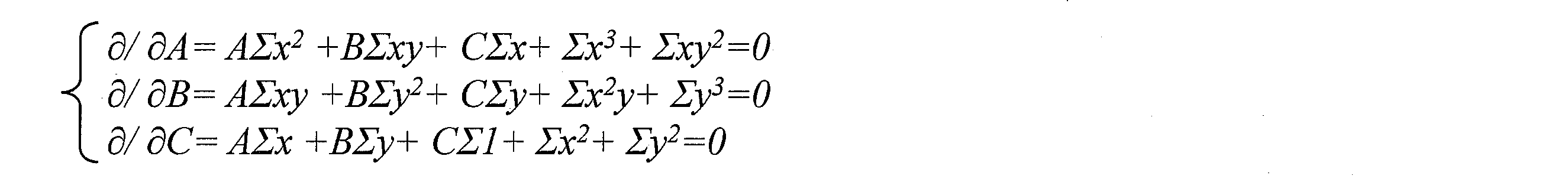
これらの式を行列演算によって解くと、次の行列式が得られる。
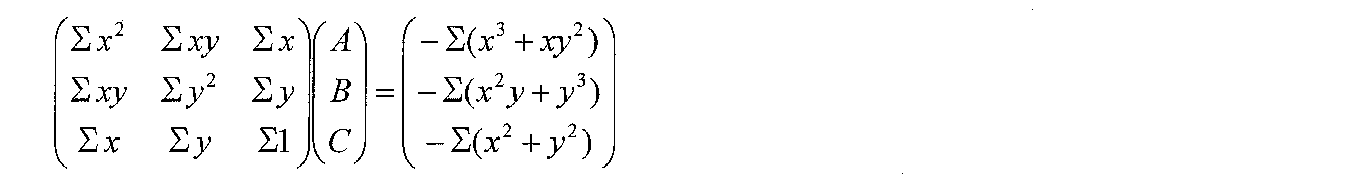
この行列式を展開すると、次の行列式が得られる。

この行列式を解くことによって、媒介変数A、B、およびCが決定される。決定した媒介変数A、B、およびCを、上述した関係式に代入することによって、係数a、b、およびrを決定することができる。これにより円91の方程式が算出されるので、これを用いて中心点92を算出する。中心点92に基づく対地絶縁抵抗分の漏洩電流I0_sysの算出、ならびに漏洩電流I0_sysおよび対地電圧Vs∠180°に基づく三相モーター5の対地絶縁抵抗の算出は、上述した例と変わりない。
E = Σ (x 2 + y 2 + Ax + By + C)
Here, A = −2a, B = −2b, and C = a 2 + b 2 −r 2 . When this differential equation is partially differentiated, the following equation is obtained.
When these equations are solved by matrix operation, the following determinant is obtained.
When this determinant is expanded, the following determinant is obtained.
By solving this determinant, parameters A, B, and C are determined. The coefficients a, b, and r can be determined by substituting the determined parameters A, B, and C into the above-described relational expression. As a result, the equation of the circle 91 is calculated, and the center point 92 is calculated using this. The calculation of the leakage current I0_sys for the ground insulation resistance based on the center point 92 and the calculation of the ground insulation resistance of the three-phase motor 5 based on the leakage current I0_sys and the ground voltage Vs∠180 ° are the same as the above-described example.
ここで、A=-2a、B=-2b、C=a2+b2-r2である。この関係式を偏微分すると、次の式が得られる。
Here, A = −2a, B = −2b, and C = a 2 + b 2 −r 2 . When this differential equation is partially differentiated, the following equation is obtained.
この方法では、円91の算出に円の最小二乗法が用いられるので、円91の中心点92をより精度良く算出することができる。したがって、漏洩電流I0_sysおよび対地絶縁抵抗を、より精度良く算出することができる。
In this method, since the circle least square method is used to calculate the circle 91, the center point 92 of the circle 91 can be calculated with higher accuracy. Therefore, the leakage current I0_sys and the ground insulation resistance can be calculated with higher accuracy.
図9の(b)に、I0_sysの実際の算出結果の一例を示す。この例では、円91の方程式として、(x-0.0044)2+(y-0.0133)2=0.00392が算出された。この方程式から決定される中心点92を横軸に投影すると、値は4.4mAとなり、そのためI0R_sysとして4.4mAが算出された。この算出に用いた三相モーター5におけるI0_sysの理論値は4.3mAであるので、算出結果が理論値に良く一致したことが分かる。また、4.4mAのI0_sysを用いて算出された三相モーター5の対地絶縁抵抗は26.9kΩであり、これも理論値の27kΩに良く一致する。
FIG. 9B shows an example of the actual calculation result of I0_sys. In this example, as the equation of a circle 91, (x-0.0044) 2 + (y-0.0133) 2 = 0.0039 2 was calculated. When the center point 92 determined from this equation is projected on the horizontal axis, the value is 4.4 mA, and thus 4.4 mA is calculated as I0R_sys. Since the theoretical value of I0_sys in the three-phase motor 5 used for this calculation is 4.3 mA, it can be seen that the calculation result agrees well with the theoretical value. The ground insulation resistance of the three-phase motor 5 calculated using 4.4 mA of I0_sys is 26.9 kΩ, which also agrees well with the theoretical value of 27 kΩ.
(第3の方法)
図11は、本発明の実施形態1における対地絶縁抵抗分漏洩電流を算出するための第3の方法を説明する図である。 (Third method)
FIG. 11 is a diagram for explaining a third method for calculating the ground insulation resistance leakage current according to the first embodiment of the present invention.
図11は、本発明の実施形態1における対地絶縁抵抗分漏洩電流を算出するための第3の方法を説明する図である。 (Third method)
FIG. 11 is a diagram for explaining a third method for calculating the ground insulation resistance leakage current according to the first embodiment of the present invention.
図11の例では、系統周波数成分抽出部14は、円の中心点を直接算出するのではなく、その代わりに、一定時間内における、I0_mixにおける対地絶縁抵抗分の漏洩電流の最小値と、I0_mixのうち対地絶縁抵抗分の漏洩電流の最大値とを算出し、これらの中間値を、I0R_sysとして算出する。
In the example of FIG. 11, the system frequency component extraction unit 14 does not directly calculate the center point of the circle, but instead, the minimum value of the leakage current corresponding to the ground insulation resistance at I0_mix and the I0_mix within a certain time. Among these, the maximum value of the leakage current corresponding to the ground insulation resistance is calculated, and an intermediate value thereof is calculated as I0R_sys.
この方法では、系統周波数成分抽出部14は、一定時間内(60秒以上の長時間が望ましい)に亘る各時点において、すなわち円一周分以上の点が算出されるまで、I0_mixを抽出する。同様に、位相差算出部15は、円一周分以上の点が算出されるまで、各時点において位相差θを算出する。この方法では、円中心算出部16は円の中心を算出しない。その代わりに、絶縁抵抗算出部18が、各時点において得られた漏洩電流I0_mixおよび位相差θを用いて、各時点における漏洩電流I0_mixのうちの対地絶縁抵抗分の漏洩電流I0R_mixを算出する。これは、I0_mixにcosθを乗算することによって得られる。すなわち、I0R_mix=I0_mix×cosθである。
In this method, the system frequency component extraction unit 14 extracts I0_mix at each time point within a fixed time (preferably a long time of 60 seconds or more), that is, until a point equal to or more than one circle is calculated. Similarly, the phase difference calculation unit 15 calculates the phase difference θ at each time point until points equal to or more than one circle are calculated. In this method, the circle center calculation unit 16 does not calculate the center of the circle. Instead, the insulation resistance calculator 18 calculates the leakage current I0R_mix corresponding to the ground insulation resistance of the leakage current I0_mix at each time point using the leakage current I0_mix and the phase difference θ obtained at each time point. This is obtained by multiplying I0_mix by cos θ. That is, I0R_mix = I0_mix × cos θ.
絶縁抵抗算出部18は、I0R_mixの算出を、長時間(60秒以上)に亘る各時点において実行する。I0R_mixの値は、I0_mixをベクトル表記した際の終点を横軸に投影した点における横軸の値に一致する。この終点は上述したように円を描くので、終点を横軸に投影した点は、円全体を横軸に投影して得られる線の中に必ずある。したがって、算出されるI0R_mixには、線の端部のそれぞれ対応する最小値111および最大値112が自ずと定まる。
The insulation resistance calculation unit 18 executes the calculation of I0R_mix at each time point over a long time (60 seconds or more). The value of I0R_mix coincides with the value on the horizontal axis at the point where the end point when I0_mix is expressed in vector is projected on the horizontal axis. Since the end point draws a circle as described above, a point obtained by projecting the end point on the horizontal axis is always in a line obtained by projecting the entire circle on the horizontal axis. Therefore, the calculated minimum value 111 and the maximum value 112 corresponding to the end of the line are naturally determined in the calculated I0R_mix.
この最小値111と最大値112は、それぞれI0_mixの終点が描く円における横軸方向における各端部に対応するので、最小値111と最大値112との中間値113は、円の中心点に対応する。上述したように、円の中心点を横軸に投影した値はI0R_sysに対応するので、抵抗分漏洩電流算出部17は、中間値113を算出することによって、I0R_sysを算出することができる。
Since the minimum value 111 and the maximum value 112 correspond to each end in the horizontal axis direction of the circle drawn by the end point of I0_mix, the intermediate value 113 between the minimum value 111 and the maximum value 112 corresponds to the center point of the circle. To do. As described above, the value obtained by projecting the center point of the circle on the horizontal axis corresponds to I0R_sys. Therefore, the resistance leakage current calculation unit 17 can calculate I0R_sys by calculating the intermediate value 113.
なお、I0R_sysおよび対地電圧Vs∠180°に基づく三相モーター5の対地絶縁抵抗の算出は、上述した例と変わりない。
Note that the calculation of the ground insulation resistance of the three-phase motor 5 based on I0R_sys and the ground voltage Vs∠180 ° is the same as the above-described example.
この方法では、I0R_sysの算出のために複雑な方程式を用いて円の中心を求める必要がないので、簡単な計算によってI0R_sysを得ることができる。
In this method, since it is not necessary to obtain the center of the circle using a complicated equation for calculating I0R_sys, I0R_sys can be obtained by simple calculation.
図11の(b)に、第3の方法によるI0R_sysの実際の算出結果の一例を示す。この例では、中間値113として、すなわちI0R_sysとして、4.3mAが算出された。4.3mAのI0R_sysを用いて算出された三相モーター5の対地絶縁抵抗は27.1kΩであり、これは理論値の27kΩに良く一致する。
FIG. 11B shows an example of the actual calculation result of I0R_sys by the third method. In this example, 4.3 mA was calculated as the intermediate value 113, that is, I0R_sys. The ground insulation resistance of the three-phase motor 5 calculated using I0R_sys of 4.3 mA is 27.1 kΩ, which is in good agreement with the theoretical value of 27 kΩ.
〔実施形態2〕
図12および図13を参照して、本発明に係る実施形態2を以下に説明する。上述した実施形態1と共通する各部材には同じ符号を付し、詳細な説明を省略する。 [Embodiment 2]
With reference to FIG. 12 and FIG. 13,Embodiment 2 which concerns on this invention is demonstrated below. Each member common to Embodiment 1 described above is denoted by the same reference numeral, and detailed description thereof is omitted.
図12および図13を参照して、本発明に係る実施形態2を以下に説明する。上述した実施形態1と共通する各部材には同じ符号を付し、詳細な説明を省略する。 [Embodiment 2]
With reference to FIG. 12 and FIG. 13,
(概略構成)
図12は、本発明の実施形態2に係る漏洩電流算出装置1が適用される構成例を示す概略系統図である。本実施形態では、漏洩電流算出装置1の構成は、実施形態1と基本的に同一である。ただし本実施形態では、図12に示すように、1台の漏洩電流算出装置1は、複数の三相モーター5aおよび5bのそれぞれを監視するようにことができる。 (Outline configuration)
FIG. 12 is a schematic system diagram illustrating a configuration example to which the leakagecurrent calculation apparatus 1 according to the second embodiment of the present invention is applied. In the present embodiment, the configuration of the leakage current calculation device 1 is basically the same as that of the first embodiment. However, in this embodiment, as shown in FIG. 12, one leakage current calculation device 1 can monitor each of the plurality of three- phase motors 5a and 5b.
図12は、本発明の実施形態2に係る漏洩電流算出装置1が適用される構成例を示す概略系統図である。本実施形態では、漏洩電流算出装置1の構成は、実施形態1と基本的に同一である。ただし本実施形態では、図12に示すように、1台の漏洩電流算出装置1は、複数の三相モーター5aおよび5bのそれぞれを監視するようにことができる。 (Outline configuration)
FIG. 12 is a schematic system diagram illustrating a configuration example to which the leakage
三相モーター5aおよび5bは、それぞれインバータ3aおよび3bによって駆動される。インバータ3aおよび3bのそれぞれの入力側は、いずれも、共通の商用電力系統2に接続されている。インバータ3aの出力側は三相モーター5aに接続され、一方、インバータ3bの出力側は三相モーター5bに接続されている。
The three- phase motors 5a and 5b are driven by inverters 3a and 3b, respectively. The input sides of the inverters 3a and 3b are both connected to the common commercial power system 2. The output side of the inverter 3a is connected to the three-phase motor 5a, while the output side of the inverter 3b is connected to the three-phase motor 5b.
また、インバータ3aと三相モーター5aとの間に零相変流器4aが配置されており、一方、インバータ3bと三相モーター5bとの間に零相変流器4bが配置されている。これらの零相変流器4aおよび4bは、いずれも、漏洩電流算出装置1の漏洩電流計測部12に接続されている。
Also, a zero-phase current transformer 4a is disposed between the inverter 3a and the three-phase motor 5a, while a zero-phase current transformer 4b is disposed between the inverter 3b and the three-phase motor 5b. These zero-phase current transformers 4 a and 4 b are both connected to the leakage current measuring unit 12 of the leakage current calculating device 1.
(算出手順)
本実施形態では、漏洩電流算出装置1は、三相モーター5aおよび5bのそれぞれに対応する対地絶縁抵抗分漏洩電流および対地絶縁抵抗を算出する。その手順について、以下に説明する。 (Calculation procedure)
In the present embodiment, the leakagecurrent calculation device 1 calculates a ground insulation resistance leakage current and a ground insulation resistance corresponding to each of the three- phase motors 5a and 5b. The procedure will be described below.
本実施形態では、漏洩電流算出装置1は、三相モーター5aおよび5bのそれぞれに対応する対地絶縁抵抗分漏洩電流および対地絶縁抵抗を算出する。その手順について、以下に説明する。 (Calculation procedure)
In the present embodiment, the leakage
電圧計測部11は、複数のインバータ3aおよび3bのうちいずれかの入力側における線間電圧のうち少なくともいずれかを計測する。各インバータ3aおよび3bの入力側は共通の商用電力系統2に接続されているので、たとえばインバータ3aのR相とS相との間の電圧Rsは、インバータ3bのR相とS相との電圧Rsと完全に等しい。このように本実施形態では、電圧Rsを一カ所のみで計測すれば良いので、漏洩電流算出装置1の構成をより簡素にすることができる。
The voltage measuring unit 11 measures at least one of the line voltages on the input side of any one of the plurality of inverters 3a and 3b. Since the input sides of the inverters 3a and 3b are connected to the common commercial power system 2, for example, the voltage Rs between the R phase and the S phase of the inverter 3a is the voltage between the R phase and the S phase of the inverter 3b. Is exactly equal to Rs. As described above, in the present embodiment, the voltage Rs needs to be measured only at one place, so that the configuration of the leakage current calculation apparatus 1 can be further simplified.
対地電圧算出部13は、インバータ3aの入力側から計測された電圧Rsに基づき、対地電圧Vs∠180°を算出する。電圧Rsがインバータ3aおよび3bに共通していることから、漏洩電流算出装置1は、電圧Vs∠180°を三相モーター5aおよび三相モーター5bに共通する対地電圧として、以下の処理で用いる。
The ground voltage calculation unit 13 calculates the ground voltage Vs∠180 ° based on the voltage Rs measured from the input side of the inverter 3a. Since voltage Rs is common to inverters 3a and 3b, leakage current calculation device 1 uses voltage Vs 電 圧 180 ° as a ground voltage common to three-phase motor 5a and three-phase motor 5b in the following processing.
漏洩電流計測部12は、零相変流器4aを通じて三相モーター5aの漏洩電流を計測すると共に、零相変流器4bを通じて三相モーター5bの漏洩電流を計測する。すなわち漏洩電流算出装置1は、三相モーター5aおよび5bに対して共通する1つの漏洩電流計測部12を備えている。
The leakage current measuring unit 12 measures the leakage current of the three-phase motor 5a through the zero-phase current transformer 4a, and measures the leakage current of the three-phase motor 5b through the zero-phase current transformer 4b. That is, the leakage current calculation device 1 includes one leakage current measuring unit 12 that is common to the three- phase motors 5a and 5b.
なお、漏洩電流算出装置1は、各三相モーター5aおよび5bのそれぞれに対応する複数の漏洩電流計測部12aおよび12bを備えていても良い。この構成、漏洩電流計測部12aが零相変流器4a接続され、一方、漏洩電流計測部12bが、零相変流器4bに接続されている。そして、漏洩電流計測部12aが零相変流器4aを通じて三相モーター5aの漏洩電流を計測し、一方、漏洩電流計測部12bが、零相変流器4bを通じて三相モーター5bの漏洩電流を計測する。
Note that the leakage current calculation device 1 may include a plurality of leakage current measuring units 12a and 12b corresponding to the three- phase motors 5a and 5b, respectively. In this configuration, the leakage current measuring unit 12a is connected to the zero-phase current transformer 4a, while the leakage current measuring unit 12b is connected to the zero-phase current transformer 4b. The leakage current measurement unit 12a measures the leakage current of the three-phase motor 5a through the zero-phase current transformer 4a, while the leakage current measurement unit 12b calculates the leakage current of the three-phase motor 5b through the zero-phase current transformer 4b. measure.
系統周波数成分抽出部14は、三相モーター5aの漏洩電流から、三相モーター5aに対応する漏洩電流成分を抽出する。一方、三相モーター5bの漏洩電流から、三相モーター5bに対応する漏洩電流成分を抽出する。
The system frequency component extraction unit 14 extracts a leakage current component corresponding to the three-phase motor 5a from the leakage current of the three-phase motor 5a. On the other hand, a leakage current component corresponding to the three-phase motor 5b is extracted from the leakage current of the three-phase motor 5b.
位相差算出部15は、算出された対地電圧と、三相モーター5aの漏洩電流成分との間の位相差を算出する。さらに、算出された対地電圧と、三相モーター5bの漏洩電流成分との間の位相差を算出する。
The phase difference calculation unit 15 calculates the phase difference between the calculated ground voltage and the leakage current component of the three-phase motor 5a. Furthermore, the phase difference between the calculated ground voltage and the leakage current component of the three-phase motor 5b is calculated.
抵抗分漏洩電流算出部17は、三相モーター5aに対応する円の中心点に基づき、三相モーター5aの対地絶縁抵抗分漏洩電流を算出する。また、三相モーター5bに対応する円の中心点に基づき、三相モーター5bの対地絶縁抵抗分漏洩電流を算出する。
The resistance leakage current calculation unit 17 calculates a ground insulation resistance leakage current of the three-phase motor 5a based on the center point of the circle corresponding to the three-phase motor 5a. Further, the leakage current corresponding to the ground insulation resistance of the three-phase motor 5b is calculated based on the center point of the circle corresponding to the three-phase motor 5b.
絶縁抵抗算出部18は、対地電圧Vs∠180°と、三相モーター5aの対地絶縁抵抗分漏洩電流とから、三相モーター5aの対地絶縁抵抗を算出する。また、対地電圧Vs∠180°と、三相モーター5bの対地絶縁抵抗分漏洩電流とから、三相モーター5bの対地絶縁抵抗を算出する。
The insulation resistance calculation unit 18 calculates the ground insulation resistance of the three-phase motor 5a from the ground voltage Vs∠180 ° and the leakage current corresponding to the ground insulation resistance of the three-phase motor 5a. Further, the ground insulation resistance of the three-phase motor 5b is calculated from the ground voltage Vs∠180 ° and the leakage current corresponding to the ground insulation resistance of the three-phase motor 5b.
図13は、本発明の実施形態2における三相モーター5ごとの対地絶縁抵抗分漏洩電流または対地絶縁抵抗の算出値の時間的推移の一例を示す図である。図13の(a)は、三相モーター5aおよび5bのそれぞれの対地絶縁抵抗分漏洩電流の時間的推移を示す。図中、Ch1が三相モーター5aに対応し、Ch2が三相モーター5bに対応する。一方、図13の(b)は、三相モーター5aおよび5bのそれぞれの対地絶縁抵抗の時間的推移を示す。図中、Ch1が三相モーター5aに対応し、Ch2が三相モーター5bに対応する。これらの図では、対地絶縁抵抗分漏洩電流または対地絶縁抵抗の時間的変化が三相モーター5aと5bとでそれぞれ異なっている。漏洩電流算出装置1は、相互の値を比較したり、あるいはそれぞれの値を所定の閾値と比較したりすることによって、絶縁劣化している三相モーター5を適宜特定することができる。
FIG. 13 is a diagram illustrating an example of a temporal transition of the ground insulation resistance-divided leakage current or the calculated value of the ground insulation resistance for each of the three-phase motors 5 according to the second embodiment of the present invention. (A) of FIG. 13 shows the time transition of each earth insulation resistance part leakage current of each of the three- phase motors 5a and 5b. In the figure, Ch1 corresponds to the three-phase motor 5a, and Ch2 corresponds to the three-phase motor 5b. On the other hand, FIG. 13B shows the temporal transition of the ground insulation resistance of each of the three- phase motors 5a and 5b. In the figure, Ch1 corresponds to the three-phase motor 5a, and Ch2 corresponds to the three-phase motor 5b. In these drawings, the three- phase motors 5a and 5b have different temporal changes in the ground insulation resistance-divided leakage current or the ground insulation resistance, respectively. The leakage current calculation device 1 can appropriately identify the three-phase motor 5 that has undergone insulation degradation by comparing values with each other or by comparing each value with a predetermined threshold value.
(乖離度合いに基づく判定)
判定部19は、三相モーター5aの系統周波数分の対地絶縁抵抗分漏洩電流と、三相モーター5bの系統周波数分の対地絶縁抵抗分漏洩電流とを互いに比較することによって、三相モーター5aおよび5bにおける絶縁劣化の度合いをそれぞれ判定することができる。たとえば、図13の(a)の例では、ある時点における三相モーター5aの系統周波数分の対地絶縁抵抗分漏洩電流と、同じ時点における三相モーター5bの系統周波数分の対地絶縁抵抗分漏洩電流との間に、大きな乖離度131が生じている。判定部19は、この乖離度131を検出した場合、より対地絶縁抵抗分漏洩電流の大きい三相モーター5aの方が、絶縁劣化していると判定する。 (Judgment based on the degree of deviation)
Thedetermination unit 19 compares the ground insulation resistance leakage current corresponding to the system frequency of the three-phase motor 5a with the ground insulation resistance leakage current corresponding to the system frequency of the three-phase motor 5b. The degree of insulation deterioration in 5b can be determined respectively. For example, in the example of FIG. 13 (a), the ground insulation resistance leakage current corresponding to the system frequency of the three-phase motor 5a at a certain time and the ground insulation resistance leakage current corresponding to the system frequency of the three-phase motor 5b at the same time. A large degree of divergence 131 occurs between the two. When the determination unit 19 detects the degree of divergence 131, the determination unit 19 determines that the three-phase motor 5 a having a larger leakage current with respect to the ground insulation resistance has deteriorated the insulation.
判定部19は、三相モーター5aの系統周波数分の対地絶縁抵抗分漏洩電流と、三相モーター5bの系統周波数分の対地絶縁抵抗分漏洩電流とを互いに比較することによって、三相モーター5aおよび5bにおける絶縁劣化の度合いをそれぞれ判定することができる。たとえば、図13の(a)の例では、ある時点における三相モーター5aの系統周波数分の対地絶縁抵抗分漏洩電流と、同じ時点における三相モーター5bの系統周波数分の対地絶縁抵抗分漏洩電流との間に、大きな乖離度131が生じている。判定部19は、この乖離度131を検出した場合、より対地絶縁抵抗分漏洩電流の大きい三相モーター5aの方が、絶縁劣化していると判定する。 (Judgment based on the degree of deviation)
The
(閾値に基づく判定)
判定部19は、三相モーター5aおよび5bのうち、対応する対地絶縁抵抗分漏洩電流が規定の閾値を上回る三相モーター5aを、絶縁劣化している三相モーター5aとして特定することもできる。たとえば図13の(a)では、三相モーター5aの対地絶縁抵抗分漏洩電流がある時点以降では閾値132を上回っているので、判定部19は、この時点以降、三相モーター5aが絶縁劣化していることを特定することができる。 (Decision based on threshold)
Thedetermination unit 19 can also identify the three-phase motor 5a in which the leakage current corresponding to the ground insulation resistance exceeds the specified threshold among the three- phase motors 5a and 5b as the three-phase motor 5a that has undergone insulation degradation. For example, in FIG. 13A, since the threshold current 132 is exceeded after a point in time when the leakage current for the ground insulation resistance of the three-phase motor 5a is present, the determination unit 19 causes the three-phase motor 5a to undergo insulation deterioration after this point. Can be identified.
判定部19は、三相モーター5aおよび5bのうち、対応する対地絶縁抵抗分漏洩電流が規定の閾値を上回る三相モーター5aを、絶縁劣化している三相モーター5aとして特定することもできる。たとえば図13の(a)では、三相モーター5aの対地絶縁抵抗分漏洩電流がある時点以降では閾値132を上回っているので、判定部19は、この時点以降、三相モーター5aが絶縁劣化していることを特定することができる。 (Decision based on threshold)
The
なお、上述した乖離度または閾値を用いた判定は、対地絶縁抵抗分漏洩電流のみならず、図13の(b)に示すように、三相モーター5aおよび5bの対地絶縁抵抗を対象としても行うことができる。たとえば、図13の(b)では、ある時点における三相モーター5aの対地絶縁抵抗と、同じ時点における三相モーター5bの対地絶縁抵抗との間に、大きな乖離度133が生じている。判定部19は、この乖離度133を検出した場合、より対地絶縁抵抗の小さい三相モーター5aの方が、絶縁劣化していると判定する。また、図13の(b)では、三相モーター5aの対地絶縁抵抗がある時点以降では閾値134を下回っているので、判定部19は、この時点以降、三相モーター5aが絶縁劣化していることを特定することができる。
Note that the determination using the above-described divergence or threshold value is performed not only on the ground insulation resistance component leakage current but also on the ground insulation resistances of the three- phase motors 5a and 5b as shown in FIG. 13B. be able to. For example, in FIG. 13B, a large degree of divergence 133 occurs between the ground insulation resistance of the three-phase motor 5a at a certain time point and the ground insulation resistance of the three-phase motor 5b at the same time point. When the determination unit 19 detects the degree of divergence 133, the determination unit 19 determines that the three-phase motor 5a having a smaller ground insulation resistance is deteriorated in insulation. Further, in FIG. 13B, since the ground insulation resistance of the three-phase motor 5a is below the threshold value 134 after the point in time, the determination unit 19 determines that the three-phase motor 5a has undergone insulation deterioration after this point. Can be specified.
(変形例)
漏洩電流算出装置1が複数の漏洩電流計測部12を備えている構成では、監視対象としない三相モーター5の漏洩電流を計測するための漏洩電流計測部12は不要である。漏洩電流算出装置1がこのような不要な漏洩電流計測部12を備えていることは、漏洩電流算出装置1の無駄なコストアップに繋がる。 (Modification)
In the configuration in which the leakagecurrent calculation device 1 includes a plurality of leakage current measuring units 12, the leakage current measuring unit 12 for measuring the leakage current of the three-phase motor 5 that is not a monitoring target is not necessary. The leakage current calculation device 1 having such an unnecessary leakage current measurement unit 12 leads to a wasteful cost increase of the leakage current calculation device 1.
漏洩電流算出装置1が複数の漏洩電流計測部12を備えている構成では、監視対象としない三相モーター5の漏洩電流を計測するための漏洩電流計測部12は不要である。漏洩電流算出装置1がこのような不要な漏洩電流計測部12を備えていることは、漏洩電流算出装置1の無駄なコストアップに繋がる。 (Modification)
In the configuration in which the leakage
これを防ぐために、各漏洩電流計測部12は、漏洩電流を計測するための増設ユニットであっても良い。この場合、必要な数だけの漏洩電流計測部12を漏洩電流算出装置1に搭載したり、あるいは不要となった漏洩電流計測部12を漏洩電流算出装置1から取り外したりすることができるので、漏洩電流算出装置1のコストを抑えることができる。なお、漏洩電流計測部12をこのような増設ユニットとして実現するためには、たとえば日本国公開特許公報「特開2013-181813号」に開示される技術を用いれば良い。
In order to prevent this, each leakage current measuring unit 12 may be an extension unit for measuring the leakage current. In this case, it is possible to mount the necessary number of leakage current measuring units 12 in the leakage current calculating device 1 or to remove the leakage current measuring unit 12 that is no longer needed from the leakage current calculating device 1. The cost of the current calculation device 1 can be suppressed. In order to realize the leakage current measuring unit 12 as such an extension unit, for example, a technique disclosed in Japanese Patent Application Laid-Open Publication No. 2013-181813 may be used.
〔まとめ〕
本発明の態様1に係る漏洩電流算出装置は、前記の課題を解決するために、異なる三相のうちいずれかが接地されている三相交流式の商用電力系統を電源とするインバータの入力側における線間電圧のうち少なくともいずれかを計測する電圧計測部と、前記電圧計測部によって計測された少なくともいずれかの前記線間電圧から、前記商用電力系統の中性点と大地との間の対地電圧を算出する対地電圧算出部と、前記インバータの出力側に接続される負荷と前記大地との間を流れる漏洩電流を計測する漏洩電流計測部と、計測された漏洩電流から、前記商用電力系統の系統周波数に同期する漏洩電流成分を抽出する周波数成分抽出部と、算出された前記対地電圧と、抽出された前記漏洩電流成分との位相差を決定する位相差決定部と、少なくとも3つの異なる時点において抽出された前記漏洩電流成分および決定された前記位相差によって特定される各特定点が描く円の中心点に基づき、前記負荷と前記大地との間を前記負荷の対地絶縁抵抗を通じて流れる前記系統周波数分の対地絶縁抵抗分漏洩電流を算出する漏洩電流算出部とを備えていることを特徴としている。 [Summary]
In order to solve the above-described problem, the leakage current calculation apparatus according toaspect 1 of the present invention has an input side of an inverter whose power source is a three-phase AC commercial power system in which one of different three phases is grounded. A voltage measurement unit that measures at least one of the line voltages in the line, and a ground between the neutral point of the commercial power system and the ground from at least one of the line voltages measured by the voltage measurement unit A ground voltage calculation unit for calculating a voltage, a leakage current measurement unit for measuring a leakage current flowing between the load connected to the output side of the inverter and the ground, and the commercial power system from the measured leakage current A frequency component extraction unit that extracts a leakage current component that is synchronized with the system frequency, a phase difference determination unit that determines a phase difference between the calculated ground voltage and the extracted leakage current component, and The ground isolation of the load between the load and the ground based on the center point of the circle drawn by the specific points identified by the leakage current component extracted at three different time points and the determined phase difference And a leakage current calculation unit for calculating a leakage current corresponding to the ground insulation resistance corresponding to the system frequency flowing through the resistor.
本発明の態様1に係る漏洩電流算出装置は、前記の課題を解決するために、異なる三相のうちいずれかが接地されている三相交流式の商用電力系統を電源とするインバータの入力側における線間電圧のうち少なくともいずれかを計測する電圧計測部と、前記電圧計測部によって計測された少なくともいずれかの前記線間電圧から、前記商用電力系統の中性点と大地との間の対地電圧を算出する対地電圧算出部と、前記インバータの出力側に接続される負荷と前記大地との間を流れる漏洩電流を計測する漏洩電流計測部と、計測された漏洩電流から、前記商用電力系統の系統周波数に同期する漏洩電流成分を抽出する周波数成分抽出部と、算出された前記対地電圧と、抽出された前記漏洩電流成分との位相差を決定する位相差決定部と、少なくとも3つの異なる時点において抽出された前記漏洩電流成分および決定された前記位相差によって特定される各特定点が描く円の中心点に基づき、前記負荷と前記大地との間を前記負荷の対地絶縁抵抗を通じて流れる前記系統周波数分の対地絶縁抵抗分漏洩電流を算出する漏洩電流算出部とを備えていることを特徴としている。 [Summary]
In order to solve the above-described problem, the leakage current calculation apparatus according to
商用電力系統の系統周波数とインバータの運転周波数とが一致する場合、漏洩電流から抽出される漏洩電流成分には、系統周波数に同期する漏洩電流と運転周波数に同期する漏洩電流との双方が含まれている。両者の周波数は厳密には一致せず、相互にわずかにずれているため、対地電圧と漏洩電流成分との位相差は、計測時点ごとに互いにずれてゆく。そのため、漏洩電流成分と位相差とによって規定される点は、計測時点ごとに変化し円を描く。
When the grid frequency of the commercial power system matches the operating frequency of the inverter, the leakage current component extracted from the leakage current includes both the leakage current synchronized with the grid frequency and the leakage current synchronized with the operation frequency. ing. Since the frequencies of the two do not exactly match each other and are slightly shifted from each other, the phase difference between the ground voltage and the leakage current component is shifted from each other at each measurement time point. Therefore, the point defined by the leakage current component and the phase difference changes at each measurement time and draws a circle.
ここで、前記の構成によれば、漏洩電流算出装置は、少なくとも3つの異なる時点において抽出された漏洩電流成分および算出された位相差によって特定される各特定点が描く円の中心点に基づき、負荷と大地との間を負荷の対地絶縁抵抗を通じて流れる系統周波数分の対地絶縁抵抗分漏洩電流を算出する。この円の中心点は、漏洩電流成分に含まれる系統周波数分の漏洩電流を表すベクトルの終点に対応する。そのため、漏洩電流算出装置はこの中心点に基づくことによって、系統周波数分の漏洩電流のうちの対地絶縁抵抗分の漏洩電流を精度良く算出することができる。
Here, according to the above configuration, the leakage current calculation device is based on the center point of a circle drawn by each specific point specified by the leakage current component extracted at the three different time points and the calculated phase difference, The leakage current corresponding to the ground insulation resistance corresponding to the system frequency flowing between the load and the ground through the ground insulation resistance of the load is calculated. The center point of this circle corresponds to the end point of the vector representing the leakage current corresponding to the system frequency included in the leakage current component. Therefore, the leakage current calculation device can accurately calculate the leakage current corresponding to the ground insulation resistance out of the leakage current corresponding to the system frequency based on the center point.
以上のように、本発明の態様1に係る漏洩電流算出装置によれば、商用電力系統の系統周波数と、インバータ機器の運転周波数とが一致する場合に、系統周波数分の対地絶縁抵抗分漏洩電流を精度良く算出することができる。
As described above, according to the leakage current calculation apparatus according to aspect 1 of the present invention, when the system frequency of the commercial power system matches the operation frequency of the inverter device, the leakage current corresponding to the ground insulation resistance corresponding to the system frequency Can be calculated with high accuracy.
本発明の態様2に係る漏洩電流算出装置は、前記態様1において、算出された前記対地電圧と、算出された前記系統周波数分の対地絶縁抵抗分漏洩電流とに基づき、前記インバータの出力側における前記負荷の対地絶縁抵抗を算出する対地絶縁抵抗算出部をさらに備えていることを特徴としている。
A leakage current calculation device according to aspect 2 of the present invention is the leakage current calculation apparatus according to aspect 1, wherein the leakage current is calculated on the output side of the inverter based on the calculated ground voltage and the calculated ground insulation resistance component leakage current corresponding to the system frequency. A ground insulation resistance calculation unit for calculating a ground insulation resistance of the load is further provided.
前記の構成によれば、負荷の対地絶縁抵抗をより精度良く算出することができる。
According to the above configuration, the ground insulation resistance of the load can be calculated with higher accuracy.
本発明の態様3に係る漏洩電流算出装置は、前記態様1または2において、前記漏洩電流算出部は、3つの前記特定点によって規定される三角形に外接する外接円の方程式に基づき、前記円の中心点を特定することを特徴としている。
The leakage current calculation device according to aspect 3 of the present invention is the leakage current calculation apparatus according to aspect 1 or 2, wherein the leakage current calculation unit is based on an equation of a circumscribed circle circumscribing a triangle defined by the three specific points. It is characterized by specifying the center point.
前記の構成によれば、系統周波数分の対地抵抗分漏洩電流を、より高速に算出することができる。
According to the above-described configuration, the ground resistance leakage current corresponding to the system frequency can be calculated at higher speed.
本発明の態様4に係る漏洩電流算出装置は、前記態様1または2において、前記漏洩電流算出部は、円の最小二乗法に基づき、前記円の中心点を特定することを特徴としている。
The leakage current calculation apparatus according to aspect 4 of the present invention is characterized in that, in the aspect 1 or 2, the leakage current calculation unit specifies a center point of the circle based on a least square method of the circle.
前記の構成によれば、系統周波数分の対地抵抗分漏洩電流を、より精度良く算出することができる。
According to the above configuration, the ground resistance leakage current corresponding to the system frequency can be calculated with higher accuracy.
本発明の態様5に係る漏洩電流算出装置は、前記態様1または2において、前記漏洩電流算出部は、一定時間内の各時点において抽出された前記漏洩電流成分および決定された前記位相差とに基づき、前記各時点における対地絶縁抵抗分漏洩電流をそれぞれ算出し、さらに、算出された各値のうち最大値と最小値との中間値を、前記系統周波数分の対地絶縁抵抗分漏洩電流として算出することを特徴としている。
The leakage current calculation apparatus according to Aspect 5 of the present invention is the leakage current calculation device according to Aspect 1 or 2, wherein the leakage current calculation unit is configured to extract the leakage current component extracted at each time point within a predetermined time and the determined phase difference. Based on the calculated values, the ground insulation resistance leakage current at each time point is calculated, and the intermediate value between the maximum and minimum values is calculated as the ground insulation resistance leakage current for the system frequency. It is characterized by doing.
前記の構成によれば、複雑な演算を用いずに、系統周波数分の対地抵抗分漏洩電流を算出することができる。
According to the above configuration, it is possible to calculate the ground resistance component leakage current corresponding to the system frequency without using a complicated calculation.
本発明の態様6に係る漏洩電流算出装置は、前記態様1~5において、複数の前記インバータのそれぞれの出力側に、複数の前記負荷のそれぞれが個別に接続されており、複数の前記インバータのそれぞれの前記入力側が、同じ前記商用電力系統に接続されており、前記電圧計測部は、複数の前記インバータのうちいずれかの前記入力側における前記線間電圧のうち少なくともいずれかを計測し、前記漏洩電流計測部は、複数の前記負荷のそれぞれに対応する複数の前記漏洩電流を計測し、前記周波数成分抽出部は、計測された複数の前記漏洩電流のそれぞれから、複数の前記負荷のそれぞれに対応する複数の前記漏洩電流成分を抽出し、前記位相差決定部は、算出された前記対地電圧と、抽出された複数の前記漏洩電流成分とに基づき、複数の位相差を決定し、前記漏洩電流算出部は、前記複数の負荷のそれぞれに対応する複数の前記円の中心点に基づき、前記負荷のそれぞれに対応する複数の前記系統周波数分の対地絶縁抵抗分漏洩電流を算出することを特徴としている。
In the leakage current calculation device according to aspect 6 of the present invention, in each of the aspects 1 to 5, each of the plurality of loads is individually connected to the output side of each of the plurality of inverters. Each of the input sides is connected to the same commercial power system, and the voltage measurement unit measures at least one of the line voltages on the input side of any of the plurality of inverters, The leakage current measurement unit measures a plurality of leakage currents corresponding to each of the plurality of loads, and the frequency component extraction unit applies each of the plurality of measured leakage currents to each of the plurality of loads. Extracting a plurality of corresponding leakage current components, the phase difference determination unit, based on the calculated ground voltage and the plurality of extracted leakage current components, A plurality of phase differences, and the leakage current calculation unit is configured to ground isolation for a plurality of system frequencies corresponding to each of the loads based on center points of the plurality of circles corresponding to the plurality of loads. It is characterized by calculating a resistance leakage current.
前記の構成によれば、複数の異なる負荷の系統周波数分の対地抵抗分漏洩電流を、1台の漏洩電流算出装置によって算出することができる。また、電圧計測部による電圧の計測は、複数のインバータのうちいずれかの入力側で良いので、電圧の計測を一カ所のみとすることができる。これにより、漏洩電流算出装置の構成をより簡素にすることができる。
According to the above-described configuration, the ground resistance component leakage current corresponding to the system frequency of a plurality of different loads can be calculated by one leakage current calculation device. Moreover, since the voltage measurement by the voltage measurement unit may be performed at any one of the plurality of inverters, the voltage can be measured only at one place. Thereby, the configuration of the leakage current calculation device can be further simplified.
本発明の態様7に係る漏洩電流算出装置は、前記態様6において、複数の前記負荷のうち、対応する前記系統周波数分の対地絶縁抵抗分漏洩電流が規定の閾値を超えた前記負荷を、絶縁劣化している前記負荷として特定する絶縁劣化負荷特定部をさらに備えていることを特徴としている。
The leakage current calculation apparatus according to Aspect 7 of the present invention is the leakage current calculation apparatus according to Aspect 6, in which the load having a leakage current corresponding to the ground insulation resistance corresponding to the system frequency exceeds a predetermined threshold among the plurality of loads. An insulation degradation load identifying unit that identifies the degraded load is further provided.
前記の構成によれば、絶縁劣化を起こした負荷を精度良く特定することができる。
According to the above configuration, it is possible to accurately identify the load that has caused the insulation deterioration.
本発明の態様8に係る漏洩電流算出装置は、前記態様6または7において、複数の前記系統周波数分の対地絶縁抵抗分漏洩電流を互いに比較することによって、複数の前記負荷における絶縁劣化の度合いをそれぞれ判定する絶縁劣化判定部をさらに備えていることを特徴としている。
In the aspect 6 or 7, the leakage current calculation apparatus according to aspect 8 of the present invention compares the ground insulation resistance leakage currents corresponding to the plurality of system frequencies with each other to thereby determine the degree of insulation deterioration in the plurality of loads. It further comprises an insulation deterioration determining unit for determining each.
前記の構成によれば、絶縁劣化を起こした負荷を精度良く特定することができる。
According to the above configuration, it is possible to accurately identify the load that has caused the insulation deterioration.
本発明の態様9に係る漏洩電流算出方法は、前記の課題を解決するために、異なる三相のうちいずれかが接地されている三相交流式の商用電力系統を電源とするインバータの入力側における線間電圧のうち少なくともいずれかを計測する電圧計測工程と、計測された前記少なくともいずれかの線間電圧から、前記商用電力系統の中性点と大地との間の対地電圧を算出する対地電圧算出工程と、前記インバータの出力側に接続される負荷と、前記大地との間を流れる漏洩電流を計測する漏洩電流計測工程と、計測された前記漏洩電流から、前記商用電力系統の系統周波数に同期する漏洩電流成分を抽出する周波数成分抽出工程と、算出された前記対地電圧と、決定された前記漏洩電流成分との位相差を決定する位相差決定工程と、少なくとも3つの異なる時点において抽出された前記漏洩電流成分および決定された前記位相差によって特定される各特定点が描く円の中心点に基づき、前記負荷と前記大地との間を前記負荷の対地絶縁抵抗を通じて流れる前記系統周波数分の前記対地絶縁抵抗分漏洩電流を算出する漏洩電流算出工程とを有することを特徴としている。
In order to solve the above-described problem, a leakage current calculation method according to aspect 9 of the present invention is provided on the input side of an inverter that uses a three-phase AC commercial power system that is grounded as one of three different phases. A voltage measurement step for measuring at least one of the line voltages in the line, and a ground voltage for calculating a ground voltage between the neutral point of the commercial power system and the ground from the measured line voltage A voltage calculation step, a leakage current measurement step for measuring a leakage current flowing between the load connected to the output side of the inverter and the ground, and a system frequency of the commercial power system from the measured leakage current A frequency component extraction step of extracting a leakage current component synchronized with the phase difference determination step of determining a phase difference between the calculated ground voltage and the determined leakage current component, and at least Based on the center point of a circle drawn by each of the specific points specified by the leakage current component extracted at two different time points and the determined phase difference, the load and the ground are connected to each other through the ground insulation resistance of the load. A leakage current calculating step of calculating a leakage current corresponding to the ground insulation resistance corresponding to the flowing system frequency.
前記の構成によれば、商用電力系統の系統周波数と、インバータ機器の運転周波数とが一致する場合に、系統周波数分の対地絶縁抵抗分漏洩電流を精度良く算出することができる。
According to the above configuration, when the system frequency of the commercial power system matches the operation frequency of the inverter device, it is possible to accurately calculate the ground insulation resistance leakage current for the system frequency.
本発明は上述した各実施形態に限定されるものではなく、請求項に示した範囲で種々の変更が可能である。異なる実施形態にそれぞれ開示された技術的手段を適宜組み合わせて得られる実施形態も、本発明の技術的範囲に含まれる。各実施形態にそれぞれ開示された技術的手段を組み合わせることによって、新しい技術的特徴を形成することもできる。
The present invention is not limited to the above-described embodiments, and various modifications can be made within the scope shown in the claims. Embodiments obtained by appropriately combining technical means disclosed in different embodiments are also included in the technical scope of the present invention. A new technical feature can also be formed by combining the technical means disclosed in each embodiment.
11 電圧計測部
12 漏洩電流計測部
13 対地電圧算出部
14 系統周波数成分抽出部(周波数成分抽出部)
15 位相差算出部(位相差決定部)
16 円中心算出部
17 抵抗分漏洩電流算出部(漏洩電流算出部)
18 絶縁抵抗算出部
19 判定部(絶縁劣化負荷特定部、絶縁劣化判定部)
20 出力部 11Voltage Measurement Unit 12 Leakage Current Measurement Unit 13 Ground Voltage Calculation Unit 14 System Frequency Component Extraction Unit (Frequency Component Extraction Unit)
15 Phase difference calculation unit (phase difference determination unit)
16 Circlecenter calculation unit 17 Resistance leakage current calculation unit (leakage current calculation unit)
18 Insulationresistance calculation unit 19 Judgment unit (insulation degradation load identification unit, insulation degradation judgment unit)
20 Output section
12 漏洩電流計測部
13 対地電圧算出部
14 系統周波数成分抽出部(周波数成分抽出部)
15 位相差算出部(位相差決定部)
16 円中心算出部
17 抵抗分漏洩電流算出部(漏洩電流算出部)
18 絶縁抵抗算出部
19 判定部(絶縁劣化負荷特定部、絶縁劣化判定部)
20 出力部 11
15 Phase difference calculation unit (phase difference determination unit)
16 Circle
18 Insulation
20 Output section
Claims (9)
- 異なる三相のうちいずれかが接地されている三相交流式の商用電力系統を電源とするインバータの入力側における線間電圧のうち少なくともいずれかを計測する電圧計測部と、
前記電圧計測部によって計測された前記少なくともいずれかの線間電圧から、前記商用電力系統の中性点と大地と間の対地電圧を算出する対地電圧算出部と、
前記インバータの出力側に接続される負荷と前記大地との間を流れる漏洩電流を計測する漏洩電流計測部と、
計測された前記漏洩電流から、前記商用電力系統の系統周波数に同期する漏洩電流成分を抽出する周波数成分抽出部と、
算出された前記対地電圧と、抽出された前記漏洩電流成分との位相差を決定する位相差決定部と、
少なくとも3つの異なる時点において抽出された前記漏洩電流成分および決定された前記位相差によって特定される各特定点が描く円の中心点に基づき、前記負荷と前記大地との間を前記負荷の対地絶縁抵抗を通じて流れる前記系統周波数分の対地絶縁抵抗分漏洩電流を算出する漏洩電流算出部とを備えていることを特徴とする漏洩電流算出装置。 A voltage measuring unit that measures at least one of the line voltages on the input side of the inverter that is powered by a three-phase AC commercial power system in which one of the three different phases is grounded;
From the at least one line voltage measured by the voltage measurement unit, a ground voltage calculation unit that calculates a ground voltage between a neutral point of the commercial power system and the ground,
A leakage current measuring unit that measures a leakage current flowing between the load connected to the output side of the inverter and the ground; and
A frequency component extraction unit that extracts a leakage current component synchronized with a system frequency of the commercial power system from the measured leakage current;
A phase difference determining unit that determines a phase difference between the calculated ground voltage and the extracted leakage current component;
Ground isolation of the load between the load and the ground based on a center point of a circle drawn by the specific points identified by the leakage current component extracted at at least three different time points and the determined phase difference A leakage current calculation device comprising: a leakage current calculation unit for calculating a leakage current corresponding to a ground insulation resistance corresponding to the system frequency flowing through the resistor. - 算出された前記対地電圧と、算出された前記系統周波数分の対地絶縁抵抗分漏洩電流とに基づき、前記インバータの出力側における対地絶縁抵抗を算出する絶縁抵抗算出部をさらに備えていることを特徴とする請求項1に記載の漏洩電流算出装置。 An insulation resistance calculation unit that calculates a ground insulation resistance on the output side of the inverter based on the calculated ground voltage and a ground insulation resistance-divided leakage current corresponding to the calculated system frequency is further provided. The leakage current calculation apparatus according to claim 1.
- 前記漏洩電流算出部は、3つの前記特定点によって規定される三角形に外接する円の方程式に基づき、前記円の中心点を特定することを特徴とする請求項1または2に記載の漏洩電流算出装置。 3. The leakage current calculation according to claim 1, wherein the leakage current calculation unit specifies a center point of the circle based on an equation of a circle circumscribing a triangle defined by the three specific points. apparatus.
- 前記漏洩電流算出部は、円の最小二乗法に基づき、前記円の中心点を特定することを特徴とする請求項1または2に記載の漏洩電流算出装置。 The leakage current calculation device according to claim 1 or 2, wherein the leakage current calculation unit specifies a center point of the circle based on a least square method of a circle.
- 前記漏洩電流算出部は、一定時間内の各時点において抽出された前記漏洩電流成分および決定された前記位相差とに基づき、前記各時点における対地絶縁抵抗分漏洩電流をそれぞれ算出し、さらに、算出された各値のうち最大値と最小値との中間値を、前記系統周波数分の前記対地絶縁抵抗分漏洩電流として算出することを特徴とする請求項1または2に記載の漏洩電流算出装置。 The leakage current calculation unit calculates a ground insulation resistance leakage current at each time point based on the leakage current component extracted at each time point within a predetermined time and the determined phase difference, and further calculates The leakage current calculation device according to claim 1, wherein an intermediate value between a maximum value and a minimum value among the obtained values is calculated as the ground insulation resistance leakage current corresponding to the system frequency.
- 複数の前記インバータのそれぞれの出力側に、複数の前記負荷のそれぞれが個別に接続されており、
複数の前記インバータのそれぞれの前記入力側が、同じ前記商用電力系統に接続されており、
前記電圧計測部は、複数の前記インバータのうちいずれかの前記入力側における前記線間電圧のうち少なくともいずれかを計測し、
前記漏洩電流計測部は、複数の前記負荷のそれぞれに対応する複数の前記漏洩電流を計測し、
前記周波数成分抽出部は、計測された複数の前記漏洩電流のそれぞれから、複数の前記負荷のそれぞれに対応する複数の前記漏洩電流成分を抽出し、
前記位相差決定部は、算出された前記対地電圧と、抽出された複数の前記漏洩電流成分とに基づき、複数の位相差を決定し、
前記漏洩電流算出部は、複数の前記負荷のそれぞれに対応する複数の前記円の中心点に基づき、前記負荷のそれぞれに対応する複数の前記系統周波数分の前記対地絶縁抵抗分漏洩電流を算出することを特徴とする請求項1~5のいずれか1項に記載の漏洩電流算出装置。 Each of the plurality of loads is individually connected to the output side of each of the plurality of inverters,
The input side of each of the plurality of inverters is connected to the same commercial power system,
The voltage measurement unit measures at least one of the line voltages on the input side of any of the plurality of inverters,
The leakage current measuring unit measures a plurality of leakage currents corresponding to each of the plurality of loads,
The frequency component extraction unit extracts a plurality of leakage current components corresponding to each of the plurality of loads from each of the measured plurality of leakage currents,
The phase difference determination unit determines a plurality of phase differences based on the calculated ground voltage and the extracted plurality of leakage current components,
The leakage current calculation unit calculates the leakage current to the ground insulation resistance corresponding to each of the plurality of system frequencies corresponding to each of the loads, based on the center points of the plurality of circles corresponding to the plurality of loads. The leakage current calculation device according to any one of claims 1 to 5, wherein - 複数の前記負荷のうち、対応する前記系統周波数分の前記対地絶縁抵抗分漏洩電流が規定の閾値を超えた前記負荷を、絶縁劣化している前記負荷として特定する絶縁劣化負荷特定部をさらに備えていることを特徴とする請求項6に記載の漏洩電流算出装置。 An insulation degradation load identifying unit that identifies, as the load that is insulation-degraded, the load in which the leakage current corresponding to the ground insulation resistance for the corresponding system frequency exceeds a predetermined threshold among the plurality of loads. The leakage current calculation apparatus according to claim 6, wherein:
- 複数の前記系統周波数分の前記対地絶縁抵抗分漏洩電流を互いに比較することによって、複数の前記負荷における絶縁劣化の度合いをそれぞれ判定する絶縁劣化判定部をさらに備えていることを特徴とする請求項6または7に記載の漏洩電流算出装置。 An insulation deterioration determination unit that determines the degree of insulation deterioration in each of the plurality of loads by comparing the leakage currents for the ground insulation resistance corresponding to the plurality of system frequencies with each other. The leakage current calculation device according to 6 or 7.
- 異なる三相のうちいずれかが接地されている三相交流式の商用電力系統を電源とするインバータの入力側における線間電圧のうち少なくともいずれかを計測する電圧計測工程と、
計測された前記少なくともいずれかの線間電圧から、前記商用電力系統の中性点と大地との間の対地電圧を算出する対地電圧算出工程と、
前記インバータの出力側に接続される負荷と前記大地との間を流れる漏洩電流を計測する漏洩電流計測工程と、
計測された前記漏洩電流から、前記商用電力系統の系統周波数に同期する漏洩電流成分を抽出する周波数成分抽出工程と、
算出された前記対地電圧と、抽出された前記漏洩電流成分との位相差を決定する位相差決定工程と、
少なくとも3つの異なる時点において抽出された前記漏洩電流成分および決定された前記位相差とによって特定される各特定点が描く円の中心点に基づき、前記負荷と前記大地との間を前記負荷の対地絶縁抵抗を通じて流れる前記系統周波数分の対地絶縁抵抗分漏洩電流を算出する漏洩電流算出工程とを有することを特徴とする漏洩電流算出方法。 A voltage measuring step for measuring at least one of the line voltages on the input side of the inverter that is powered by a three-phase AC commercial power system in which one of the three different phases is grounded;
A ground voltage calculation step of calculating a ground voltage between a neutral point of the commercial power system and the ground from the measured line voltage,
A leakage current measuring step for measuring a leakage current flowing between the load connected to the output side of the inverter and the ground; and
A frequency component extraction step for extracting a leakage current component synchronized with a system frequency of the commercial power system from the measured leakage current;
A phase difference determining step for determining a phase difference between the calculated ground voltage and the extracted leakage current component;
Based on a center point of a circle drawn by each specific point specified by the leakage current component extracted at at least three different time points and the determined phase difference, the load is grounded between the load and the ground. And a leakage current calculation step of calculating a leakage current corresponding to the ground insulation resistance corresponding to the system frequency flowing through the insulation resistance.
Priority Applications (4)
| Application Number | Priority Date | Filing Date | Title |
|---|---|---|---|
| KR1020187004138A KR102007909B1 (en) | 2016-03-09 | 2016-11-21 | Leakage Current Calculation Device and Leakage Current Calculation Method |
| CN201680047997.3A CN107923936B (en) | 2016-03-09 | 2016-11-21 | Leakage current calculation device and leakage current calculation method |
| US15/751,468 US10782359B2 (en) | 2016-03-09 | 2016-11-21 | Leakage current calculation device and leakage current calculation method |
| EP16893595.5A EP3428664B1 (en) | 2016-03-09 | 2016-11-21 | Leakage current calculation device and leakage current calculation method |
Applications Claiming Priority (2)
| Application Number | Priority Date | Filing Date | Title |
|---|---|---|---|
| JP2016046127A JP6477548B2 (en) | 2016-03-09 | 2016-03-09 | Leakage current calculation device and leakage current calculation method |
| JP2016-046127 | 2016-03-09 |
Publications (1)
| Publication Number | Publication Date |
|---|---|
| WO2017154271A1 true WO2017154271A1 (en) | 2017-09-14 |
Family
ID=59790324
Family Applications (1)
| Application Number | Title | Priority Date | Filing Date |
|---|---|---|---|
| PCT/JP2016/084416 WO2017154271A1 (en) | 2016-03-09 | 2016-11-21 | Leakage current calculation device and leakage current calculation method |
Country Status (6)
| Country | Link |
|---|---|
| US (1) | US10782359B2 (en) |
| EP (1) | EP3428664B1 (en) |
| JP (1) | JP6477548B2 (en) |
| KR (1) | KR102007909B1 (en) |
| CN (1) | CN107923936B (en) |
| WO (1) | WO2017154271A1 (en) |
Cited By (3)
| Publication number | Priority date | Publication date | Assignee | Title |
|---|---|---|---|---|
| WO2018193703A1 (en) * | 2017-04-21 | 2018-10-25 | オムロン株式会社 | Leakage current calculation device and leakage current calculation method |
| TWI696838B (en) * | 2018-03-29 | 2020-06-21 | 日商歐姆龍股份有限公司 | Insulation measuring apparatus and insulation measuring method |
| WO2020217880A1 (en) * | 2019-04-26 | 2020-10-29 | 株式会社日立製作所 | Electric machine diagnosis method and diagnosis device, and rotating electric machine |
Families Citing this family (5)
| Publication number | Priority date | Publication date | Assignee | Title |
|---|---|---|---|---|
| EP3370073B1 (en) * | 2017-03-01 | 2020-04-29 | ABB Power Grids Switzerland AG | Method and device for determining capacitive component parameters |
| US11606022B2 (en) * | 2018-01-29 | 2023-03-14 | Toshiba Mitsubishi-Electric Industrial Systems Corporation | Insulation deterioration monitoring apparatus and insulation deterioration monitoring method |
| KR102124554B1 (en) * | 2019-01-25 | 2020-06-18 | 한국전기안전공사 | Real-time remote three-phase electrical equipment live-wire leakage monitoring apparatus and method |
| DE102019107399A1 (en) * | 2019-03-22 | 2020-09-24 | Vega Grieshaber Kg | Field device with monitoring device and method for operating a field device |
| CN111768599B (en) * | 2020-07-08 | 2021-08-10 | 安徽先兆科技有限公司 | AC380V loop electric safety control method and system |
Citations (3)
| Publication number | Priority date | Publication date | Assignee | Title |
|---|---|---|---|---|
| WO2006035519A1 (en) * | 2005-01-31 | 2006-04-06 | Ohno, Takemi | Leak current breaker and method |
| JP2011153910A (en) * | 2010-01-27 | 2011-08-11 | Patokkusu Japan Kk | Leak current measuring device and measurement method in electric apparatus |
| JP5631444B1 (en) * | 2013-05-27 | 2014-11-26 | タナシン電機株式会社 | Leakage current calculation device and leakage current calculation method |
Family Cites Families (15)
| Publication number | Priority date | Publication date | Assignee | Title |
|---|---|---|---|---|
| JPS53100350A (en) | 1977-02-15 | 1978-09-01 | Nifco Inc | Fastener for jointing two panels |
| US6421618B1 (en) * | 1998-12-28 | 2002-07-16 | General Electric Company | Incipient leakage current fault detection apparatus and method |
| ES2255549T3 (en) * | 2000-04-17 | 2006-07-01 | Suparules Limited | CURRENT MEASUREMENT DEVICE. |
| JP3652584B2 (en) | 2000-06-08 | 2005-05-25 | 光商工株式会社 | Leakage detection protection method and apparatus for low-voltage ground circuit |
| CN2502278Y (en) * | 2001-08-02 | 2002-07-24 | 南京普天通信股份有限公司 | Power frequency current monitor |
| JP2007114190A (en) | 2005-09-20 | 2007-05-10 | Daihen Corp | Leakage current resistance fraction detection method and device for it |
| CN1963539B (en) * | 2005-11-09 | 2011-03-09 | 李岩松 | Optical current transformer and method for measuring current with the same |
| JP2009115754A (en) | 2007-11-09 | 2009-05-28 | Sbc Co Ltd | Device and method for measuring leakage current in electric equipment |
| CN101271130A (en) * | 2008-01-24 | 2008-09-24 | 武汉格蓝若光电互感器有限公司 | Lattice type Hall electric current transducer |
| JP5618910B2 (en) * | 2011-06-01 | 2014-11-05 | 三菱電機株式会社 | Insulation deterioration monitoring system |
| JP6222722B2 (en) | 2012-02-22 | 2017-11-01 | 株式会社三和技術総合研究所 | Power and leakage current measuring apparatus and measuring method thereof |
| JP5942506B2 (en) * | 2012-03-15 | 2016-06-29 | オムロン株式会社 | Earth leakage detector |
| CN102739066B (en) * | 2012-06-20 | 2014-12-31 | 中国计量科学研究院 | Inductive current-to-voltage converter and method for measuring high frequency current |
| JP5705382B1 (en) | 2013-11-22 | 2015-04-22 | 三菱電機株式会社 | Insulation detector and electrical equipment |
| JP5770903B1 (en) | 2014-09-26 | 2015-08-26 | タナシン電機株式会社 | Leakage current calculation device and leakage current calculation method |
-
2016
- 2016-03-09 JP JP2016046127A patent/JP6477548B2/en active Active
- 2016-11-21 WO PCT/JP2016/084416 patent/WO2017154271A1/en active Application Filing
- 2016-11-21 CN CN201680047997.3A patent/CN107923936B/en active Active
- 2016-11-21 KR KR1020187004138A patent/KR102007909B1/en active IP Right Grant
- 2016-11-21 US US15/751,468 patent/US10782359B2/en active Active
- 2016-11-21 EP EP16893595.5A patent/EP3428664B1/en active Active
Patent Citations (3)
| Publication number | Priority date | Publication date | Assignee | Title |
|---|---|---|---|---|
| WO2006035519A1 (en) * | 2005-01-31 | 2006-04-06 | Ohno, Takemi | Leak current breaker and method |
| JP2011153910A (en) * | 2010-01-27 | 2011-08-11 | Patokkusu Japan Kk | Leak current measuring device and measurement method in electric apparatus |
| JP5631444B1 (en) * | 2013-05-27 | 2014-11-26 | タナシン電機株式会社 | Leakage current calculation device and leakage current calculation method |
Non-Patent Citations (1)
| Title |
|---|
| See also references of EP3428664A4 * |
Cited By (7)
| Publication number | Priority date | Publication date | Assignee | Title |
|---|---|---|---|---|
| WO2018193703A1 (en) * | 2017-04-21 | 2018-10-25 | オムロン株式会社 | Leakage current calculation device and leakage current calculation method |
| JP2018179930A (en) * | 2017-04-21 | 2018-11-15 | オムロン株式会社 | Leakage current calculation device and leakage current calculation method |
| US11009559B2 (en) | 2017-04-21 | 2021-05-18 | Omron Corporation | Leakage current calculation method |
| TWI696838B (en) * | 2018-03-29 | 2020-06-21 | 日商歐姆龍股份有限公司 | Insulation measuring apparatus and insulation measuring method |
| WO2020217880A1 (en) * | 2019-04-26 | 2020-10-29 | 株式会社日立製作所 | Electric machine diagnosis method and diagnosis device, and rotating electric machine |
| JP2020180906A (en) * | 2019-04-26 | 2020-11-05 | 株式会社日立製作所 | Method and device for diagnosing electric machine and rotary electric machine |
| JP7218239B2 (en) | 2019-04-26 | 2023-02-06 | 株式会社日立製作所 | Electric machine diagnostic method and diagnostic device, and rotary electric machine |
Also Published As
| Publication number | Publication date |
|---|---|
| EP3428664B1 (en) | 2022-11-09 |
| CN107923936B (en) | 2020-09-04 |
| US10782359B2 (en) | 2020-09-22 |
| JP6477548B2 (en) | 2019-03-06 |
| CN107923936A (en) | 2018-04-17 |
| US20200200832A1 (en) | 2020-06-25 |
| KR102007909B1 (en) | 2019-08-06 |
| KR20180115663A (en) | 2018-10-23 |
| EP3428664A4 (en) | 2019-12-11 |
| EP3428664A1 (en) | 2019-01-16 |
| JP2017161362A (en) | 2017-09-14 |
Similar Documents
| Publication | Publication Date | Title |
|---|---|---|
| WO2017154271A1 (en) | Leakage current calculation device and leakage current calculation method | |
| JP6460146B2 (en) | Leakage current calculation device and leakage current calculation method | |
| US10585134B2 (en) | Method and system for locating ground faults in a network of drives | |
| EP1312932B1 (en) | Method for measuring motor constant of induction motor | |
| CN106133538B (en) | System and method for detecting, positioning and quantifying the stator winding faults in AC motor | |
| JP5544517B2 (en) | Leakage current measuring device and measuring method in electrical equipment | |
| US9802642B2 (en) | Phase current measurement diagnostic | |
| CN107155353A (en) | The diagnostic device of motor | |
| JP6540028B2 (en) | Phase determination support apparatus for AC three-phase electrical path, phase determination apparatus and method | |
| JP2017533688A (en) | Method and apparatus for diagnosing phase current sensor faults in a system for controlling a synchronous rotating electrical machine of a motor vehicle | |
| JP5477020B2 (en) | Leakage current measuring device and measuring method in electrical equipment | |
| US20190356256A1 (en) | Method, Computer Program Product And System For Operating An Asynchronous Machine And Asynchronous Machine | |
| KR101977861B1 (en) | Method for determining fault of motor | |
| JP2018128270A (en) | Insulation monitoring device and insulation monitoring system | |
| JP5679480B2 (en) | Indirect AC megger measuring instrument and insulation resistance measuring method | |
| JP6604882B2 (en) | Transformer high voltage side phase loss detection system | |
| JP6407969B2 (en) | Method for verifying the operation of a motor propulsion plant mounted on a motor vehicle and corresponding system | |
| JP2016197614A (en) | Instrument transformer |
Legal Events
| Date | Code | Title | Description |
|---|---|---|---|
| ENP | Entry into the national phase |
Ref document number: 20187004138 Country of ref document: KR Kind code of ref document: A |
|
| WWE | Wipo information: entry into national phase |
Ref document number: 1020187004138 Country of ref document: KR |
|
| NENP | Non-entry into the national phase |
Ref country code: DE |
|
| 121 | Ep: the epo has been informed by wipo that ep was designated in this application |
Ref document number: 16893595 Country of ref document: EP Kind code of ref document: A1 |