WO2017150025A1 - ヘッドアップディスプレイ装置 - Google Patents
ヘッドアップディスプレイ装置 Download PDFInfo
- Publication number
- WO2017150025A1 WO2017150025A1 PCT/JP2017/002843 JP2017002843W WO2017150025A1 WO 2017150025 A1 WO2017150025 A1 WO 2017150025A1 JP 2017002843 W JP2017002843 W JP 2017002843W WO 2017150025 A1 WO2017150025 A1 WO 2017150025A1
- Authority
- WO
- WIPO (PCT)
- Prior art keywords
- image
- display
- control unit
- head
- display device
- Prior art date
- Legal status (The legal status is an assumption and is not a legal conclusion. Google has not performed a legal analysis and makes no representation as to the accuracy of the status listed.)
- Ceased
Links
Images

Classifications
-
- G—PHYSICS
- G02—OPTICS
- G02B—OPTICAL ELEMENTS, SYSTEMS OR APPARATUS
- G02B27/00—Optical systems or apparatus not provided for by any of the groups G02B1/00 - G02B26/00, G02B30/00
- G02B27/01—Head-up displays
-
- G—PHYSICS
- G02—OPTICS
- G02B—OPTICAL ELEMENTS, SYSTEMS OR APPARATUS
- G02B27/00—Optical systems or apparatus not provided for by any of the groups G02B1/00 - G02B26/00, G02B30/00
- G02B27/01—Head-up displays
- G02B27/0101—Head-up displays characterised by optical features
-
- B—PERFORMING OPERATIONS; TRANSPORTING
- B60—VEHICLES IN GENERAL
- B60K—ARRANGEMENT OR MOUNTING OF PROPULSION UNITS OR OF TRANSMISSIONS IN VEHICLES; ARRANGEMENT OR MOUNTING OF PLURAL DIVERSE PRIME-MOVERS IN VEHICLES; AUXILIARY DRIVES FOR VEHICLES; INSTRUMENTATION OR DASHBOARDS FOR VEHICLES; ARRANGEMENTS IN CONNECTION WITH COOLING, AIR INTAKE, GAS EXHAUST OR FUEL SUPPLY OF PROPULSION UNITS IN VEHICLES
- B60K35/00—Instruments specially adapted for vehicles; Arrangement of instruments in or on vehicles
- B60K35/20—Output arrangements, i.e. from vehicle to user, associated with vehicle functions or specially adapted therefor
- B60K35/21—Output arrangements, i.e. from vehicle to user, associated with vehicle functions or specially adapted therefor using visual output, e.g. blinking lights or matrix displays
- B60K35/213—Virtual instruments
-
- B—PERFORMING OPERATIONS; TRANSPORTING
- B60—VEHICLES IN GENERAL
- B60K—ARRANGEMENT OR MOUNTING OF PROPULSION UNITS OR OF TRANSMISSIONS IN VEHICLES; ARRANGEMENT OR MOUNTING OF PLURAL DIVERSE PRIME-MOVERS IN VEHICLES; AUXILIARY DRIVES FOR VEHICLES; INSTRUMENTATION OR DASHBOARDS FOR VEHICLES; ARRANGEMENTS IN CONNECTION WITH COOLING, AIR INTAKE, GAS EXHAUST OR FUEL SUPPLY OF PROPULSION UNITS IN VEHICLES
- B60K35/00—Instruments specially adapted for vehicles; Arrangement of instruments in or on vehicles
- B60K35/20—Output arrangements, i.e. from vehicle to user, associated with vehicle functions or specially adapted therefor
- B60K35/21—Output arrangements, i.e. from vehicle to user, associated with vehicle functions or specially adapted therefor using visual output, e.g. blinking lights or matrix displays
- B60K35/215—Output arrangements, i.e. from vehicle to user, associated with vehicle functions or specially adapted therefor using visual output, e.g. blinking lights or matrix displays characterised by the combination of multiple visual outputs, e.g. combined instruments with analogue meters and additional displays
-
- B—PERFORMING OPERATIONS; TRANSPORTING
- B60—VEHICLES IN GENERAL
- B60K—ARRANGEMENT OR MOUNTING OF PROPULSION UNITS OR OF TRANSMISSIONS IN VEHICLES; ARRANGEMENT OR MOUNTING OF PLURAL DIVERSE PRIME-MOVERS IN VEHICLES; AUXILIARY DRIVES FOR VEHICLES; INSTRUMENTATION OR DASHBOARDS FOR VEHICLES; ARRANGEMENTS IN CONNECTION WITH COOLING, AIR INTAKE, GAS EXHAUST OR FUEL SUPPLY OF PROPULSION UNITS IN VEHICLES
- B60K35/00—Instruments specially adapted for vehicles; Arrangement of instruments in or on vehicles
- B60K35/20—Output arrangements, i.e. from vehicle to user, associated with vehicle functions or specially adapted therefor
- B60K35/21—Output arrangements, i.e. from vehicle to user, associated with vehicle functions or specially adapted therefor using visual output, e.g. blinking lights or matrix displays
- B60K35/23—Head-up displays [HUD]
-
- B—PERFORMING OPERATIONS; TRANSPORTING
- B60—VEHICLES IN GENERAL
- B60K—ARRANGEMENT OR MOUNTING OF PROPULSION UNITS OR OF TRANSMISSIONS IN VEHICLES; ARRANGEMENT OR MOUNTING OF PLURAL DIVERSE PRIME-MOVERS IN VEHICLES; AUXILIARY DRIVES FOR VEHICLES; INSTRUMENTATION OR DASHBOARDS FOR VEHICLES; ARRANGEMENTS IN CONNECTION WITH COOLING, AIR INTAKE, GAS EXHAUST OR FUEL SUPPLY OF PROPULSION UNITS IN VEHICLES
- B60K35/00—Instruments specially adapted for vehicles; Arrangement of instruments in or on vehicles
- B60K35/20—Output arrangements, i.e. from vehicle to user, associated with vehicle functions or specially adapted therefor
- B60K35/28—Output arrangements, i.e. from vehicle to user, associated with vehicle functions or specially adapted therefor characterised by the type of the output information, e.g. video entertainment or vehicle dynamics information; characterised by the purpose of the output information, e.g. for attracting the attention of the driver
-
- B—PERFORMING OPERATIONS; TRANSPORTING
- B60—VEHICLES IN GENERAL
- B60K—ARRANGEMENT OR MOUNTING OF PROPULSION UNITS OR OF TRANSMISSIONS IN VEHICLES; ARRANGEMENT OR MOUNTING OF PLURAL DIVERSE PRIME-MOVERS IN VEHICLES; AUXILIARY DRIVES FOR VEHICLES; INSTRUMENTATION OR DASHBOARDS FOR VEHICLES; ARRANGEMENTS IN CONNECTION WITH COOLING, AIR INTAKE, GAS EXHAUST OR FUEL SUPPLY OF PROPULSION UNITS IN VEHICLES
- B60K35/00—Instruments specially adapted for vehicles; Arrangement of instruments in or on vehicles
- B60K35/60—Instruments characterised by their location or relative disposition in or on vehicles
-
- B—PERFORMING OPERATIONS; TRANSPORTING
- B60—VEHICLES IN GENERAL
- B60K—ARRANGEMENT OR MOUNTING OF PROPULSION UNITS OR OF TRANSMISSIONS IN VEHICLES; ARRANGEMENT OR MOUNTING OF PLURAL DIVERSE PRIME-MOVERS IN VEHICLES; AUXILIARY DRIVES FOR VEHICLES; INSTRUMENTATION OR DASHBOARDS FOR VEHICLES; ARRANGEMENTS IN CONNECTION WITH COOLING, AIR INTAKE, GAS EXHAUST OR FUEL SUPPLY OF PROPULSION UNITS IN VEHICLES
- B60K35/00—Instruments specially adapted for vehicles; Arrangement of instruments in or on vehicles
- B60K35/80—Arrangements for controlling instruments
- B60K35/81—Arrangements for controlling instruments for controlling displays
-
- G—PHYSICS
- G09—EDUCATION; CRYPTOGRAPHY; DISPLAY; ADVERTISING; SEALS
- G09G—ARRANGEMENTS OR CIRCUITS FOR CONTROL OF INDICATING DEVICES USING STATIC MEANS TO PRESENT VARIABLE INFORMATION
- G09G5/00—Control arrangements or circuits for visual indicators common to cathode-ray tube indicators and other visual indicators
-
- G—PHYSICS
- G09—EDUCATION; CRYPTOGRAPHY; DISPLAY; ADVERTISING; SEALS
- G09G—ARRANGEMENTS OR CIRCUITS FOR CONTROL OF INDICATING DEVICES USING STATIC MEANS TO PRESENT VARIABLE INFORMATION
- G09G5/00—Control arrangements or circuits for visual indicators common to cathode-ray tube indicators and other visual indicators
- G09G5/10—Intensity circuits
-
- G—PHYSICS
- G09—EDUCATION; CRYPTOGRAPHY; DISPLAY; ADVERTISING; SEALS
- G09G—ARRANGEMENTS OR CIRCUITS FOR CONTROL OF INDICATING DEVICES USING STATIC MEANS TO PRESENT VARIABLE INFORMATION
- G09G5/00—Control arrangements or circuits for visual indicators common to cathode-ray tube indicators and other visual indicators
- G09G5/36—Control arrangements or circuits for visual indicators common to cathode-ray tube indicators and other visual indicators characterised by the display of a graphic pattern, e.g. using an all-points-addressable [APA] memory
-
- H—ELECTRICITY
- H04—ELECTRIC COMMUNICATION TECHNIQUE
- H04N—PICTORIAL COMMUNICATION, e.g. TELEVISION
- H04N5/00—Details of television systems
- H04N5/74—Projection arrangements for image reproduction, e.g. using eidophor
-
- B—PERFORMING OPERATIONS; TRANSPORTING
- B60—VEHICLES IN GENERAL
- B60K—ARRANGEMENT OR MOUNTING OF PROPULSION UNITS OR OF TRANSMISSIONS IN VEHICLES; ARRANGEMENT OR MOUNTING OF PLURAL DIVERSE PRIME-MOVERS IN VEHICLES; AUXILIARY DRIVES FOR VEHICLES; INSTRUMENTATION OR DASHBOARDS FOR VEHICLES; ARRANGEMENTS IN CONNECTION WITH COOLING, AIR INTAKE, GAS EXHAUST OR FUEL SUPPLY OF PROPULSION UNITS IN VEHICLES
- B60K2360/00—Indexing scheme associated with groups B60K35/00 or B60K37/00 relating to details of instruments or dashboards
- B60K2360/20—Optical features of instruments
- B60K2360/33—Illumination features
- B60K2360/334—Projection means
-
- G—PHYSICS
- G02—OPTICS
- G02B—OPTICAL ELEMENTS, SYSTEMS OR APPARATUS
- G02B27/00—Optical systems or apparatus not provided for by any of the groups G02B1/00 - G02B26/00, G02B30/00
- G02B27/01—Head-up displays
- G02B27/0101—Head-up displays characterised by optical features
- G02B2027/0118—Head-up displays characterised by optical features comprising devices for improving the contrast of the display / brillance control visibility
-
- G—PHYSICS
- G02—OPTICS
- G02B—OPTICAL ELEMENTS, SYSTEMS OR APPARATUS
- G02B27/00—Optical systems or apparatus not provided for by any of the groups G02B1/00 - G02B26/00, G02B30/00
- G02B27/01—Head-up displays
- G02B27/0101—Head-up displays characterised by optical features
- G02B2027/014—Head-up displays characterised by optical features comprising information/image processing systems
-
- G—PHYSICS
- G09—EDUCATION; CRYPTOGRAPHY; DISPLAY; ADVERTISING; SEALS
- G09G—ARRANGEMENTS OR CIRCUITS FOR CONTROL OF INDICATING DEVICES USING STATIC MEANS TO PRESENT VARIABLE INFORMATION
- G09G2320/00—Control of display operating conditions
- G09G2320/06—Adjustment of display parameters
- G09G2320/0686—Adjustment of display parameters with two or more screen areas displaying information with different brightness or colours
-
- G—PHYSICS
- G09—EDUCATION; CRYPTOGRAPHY; DISPLAY; ADVERTISING; SEALS
- G09G—ARRANGEMENTS OR CIRCUITS FOR CONTROL OF INDICATING DEVICES USING STATIC MEANS TO PRESENT VARIABLE INFORMATION
- G09G2380/00—Specific applications
- G09G2380/10—Automotive applications
Definitions
- This disclosure relates to a head-up display device.
- a head-up display device that displays a display image superimposed on an external real image by displaying a virtual image so that it can be visually recognized by an occupant in the vehicle by projecting a display image onto a projection member that transmits the real external image in the vehicle.
- HUD device head-up display device
- the display device disclosed in Patent Document 1 controls the projection of a display image to be displayed as a virtual image superimposed on an external real image in order to notify information to an occupant in the vehicle by controlling the display.
- the virtual image display state of the image is adjusted.
- control capable of increasing the visibility of the real external image by increasing the overall transparency of the display image is realized.
- the present disclosure aims to provide a HUD device that ensures both the visibility of an external real image and the ability to notify information by a display image.
- the head-up display device projects the display image onto a projection member that transmits the external real image in the vehicle, so that the display image superimposed on the external real image can be visually recognized by an occupant in the vehicle.
- the head-up display device includes a projection unit that projects a notification image as the display image for notifying specific information to the occupant onto the projection member.
- the head-up display device controls the projection unit to adjust the virtual image display state of the display image, and to perform display control to cut the virtual image display of a specific pixel constituting an inner part of the notification image.
- a unit is further provided.
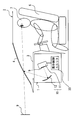
- the drawing It is a block diagram which shows the HUD apparatus of 1st embodiment, It is a front view which shows the virtual image display state by the HUD apparatus of 1st embodiment, It is a front view which shows the alerting
- the HUD device 1 As shown in FIG. 1, the HUD device 1 according to the first embodiment of the present disclosure is mounted on a vehicle 2.
- the HUD device 1 includes a projection unit 10 and a display control unit 20.
- the up-down direction and the horizontal direction in FIGS. 1 and 2 are substantially the same as the vertical direction and the horizontal direction of the vehicle 2 on the horizontal plane, respectively.
- the projection unit 10 is accommodated in the instrument panel 3 in the vehicle 2.
- the projection unit 10 includes a projector 11 and an optical system 12.
- the projector 11 is, for example, a liquid crystal projector or a scanning projector.
- the projector 11 forms and projects a color display image 9.
- the optical system 12 includes at least one optical member such as a reflecting mirror.
- the optical system 12 guides the luminous flux of the display image 9 projected from the projector 11 to the outside of the instrument panel 3 by, for example, reflection.
- the display image 9 is projected onto the front windshield 4 of the vehicle 2 by the light beam being guided by the optical system 12 as shown by the one-dot chain line in FIG.
- the front windshield 4 formed of translucent glass as a “projection member” reflects the light flux of the projected display image 9 and also emits the light flux of the external real image 5 existing in front of the outside of the vehicle 2. Make it transparent.
- the luminous flux of the display image 9 reflected by the front windshield 4 and the luminous flux of the external real image 5 transmitted through the front windshield 4 enter the pupil of the occupant 7 seated on the driver seat 6 in the vehicle 2.
- the virtual image of the display image 9 that is to be imaged ahead of the front windshield 4 in the outside of the vehicle 2 is visually recognized by the occupant 7 on the driver's seat 6 side relative to the external real image 5. That is, in the present embodiment, the display image 9 superimposed on the driver's seat 6 side of the external real image 5 is displayed as a virtual image so as to be visible by the occupant 7.
- the display image 9 displayed as a virtual image performs a notification function for notifying the occupant 7 of predetermined information in the vehicle 2.
- the notification information based on the display image 9 include instrument information such as a vehicle speed, traffic sign information such as a speed limit sign, warning information such as an overspeed warning, communication information related to a telephone or mail, route information such as turn-by-turn, and the like.
- route information is adopted as “specific information” that has little influence on compliance with traffic laws and regulations. That is, in the present embodiment, the display image 9 for informing the route information is set as the informing image 90 as shown in FIG.
- the display control unit 20 is housed in the instrument panel 3 in the vehicle 2 together with the projection unit 10.
- the display control unit 20 is mainly composed of a microcomputer and an image processing circuit.
- the display control unit 20 is electrically connected to at least the projector 11 in the projection unit 10.
- the display control unit 20 is communicably connected to electrical components required for virtual image display, such as other display control units and sensors of the vehicle 2.
- the display control unit 20 controls the projection unit 10 based on a signal from the connected electrical component. Thereby, the display control unit 20 adjusts the virtual image display state of the display image 9 including the notification image 90.
- the display control unit 20 forms a notification image 90 with the normal pixels 90a and the specific pixels 90b as shown in FIG.
- the normal pixels 90a are set to a predetermined number of pixels forming an outline of the outer shape as the outer edge portion 900 outside the one-dot chain line in the portion of the notification image 90 shown with cross hatching in FIG.
- the normal pixel 90a is the remaining portion other than the specific pixel 90b as an inner portion 901 inside the one-dot chain line, that is, inside the outer edge portion 900, of the portion indicated by cross hatching in FIG.
- the predetermined number of pixels forming 902 is also set.
- the normal pixel 90a constituting the outer edge portion 900 and the remaining portion 902 of the inner portion 901 other than the specific pixel 90b in the notification image 90 has visibility to the external real image 5 superimposed as shown in FIG. A higher contrast ratio is provided. Therefore, the display control unit 20 forms the normal pixel 90a with a relatively high luminance color tone such as white where the gradation values of RGB are all the maximum values.
- the specific pixels 90b are respectively set to a predetermined number of pixels at a plurality of locations where the normal pixels 90a are not set in the inner portion 901 of the notification image 90, as indicated by white squares in FIG.
- the virtual image display is cut so that the specific pixels 90b constituting a plurality of locations in the inner portion 901 of the notification image 90 are substantially transmitted as they are as shown in FIG.
- the notification image 90 simulates the visibility as if it is translucent. Therefore, the display control unit 20 forms the specific pixels 90b at all locations with zero luminance at which, for example, each of the RGB gradation values is a minimum value.
- the display control unit 20 adjusts the outer shape determined according to the arrangement form of the constituent pixels for each specific pixel 90b at each location to substantially the same shape.
- the display control unit 20 adjusts the lateral size Xp and the lateral spacing Xi in the horizontal direction determined according to the number of constituent pixels for each specific pixel 90b at each location to substantially constant dimensions.
- the display control unit 20 adjusts the vertical outer size Yp and the vertical layout interval Yi, which are determined according to the number of constituent pixels for each specific pixel 90b at each location, to substantially constant dimensions.
- the external sizes Xp and Yp are substantially equal so that the total area of the specific pixels 90b in each location occupies a ratio of, for example, about 20 to 70% with respect to the total area of the notification image 90.
- the specific pixels 90b at each location are formed with a square shape having the same dimensions.
- the inner portion 901 is configured with respect to the outer edge portion 900.
- the virtual image display of the specific pixel 90b is cut.
- the outside real image 5 is substantially transmitted as it is through the specific pixels 90b of the inner portion 901 where the virtual image display is cut, and at the same time, at the outer edge portion 900 and the inner portion 901 other than the specific pixels 90b.
- a highly visible contrast ratio for the external real image 5 can be provided. Therefore, it is possible to ensure both the visibility of the external real image 5 and the information notification property of the notification image 90 in a compatible manner.
- the specific pixels 90b that are cut off in the virtual image display appear at a plurality of locations in the inner portion 901 of the notification image 90, thereby increasing the number of locations where the external real image 5 is transmitted as it is. Therefore, while reliably ensuring the visibility of the external real image 5, a high contrast ratio with respect to the real external image 5 is given to the outer edge portion 900 and the inner portion 901 of the notification image 90 other than the specific pixel 90b, It is also possible to ensure information reporting.
- a plurality of locations where the specific pixels 90b to be cut in the virtual image display appear are arranged in a checkered pattern in the inner portion 901 of the notification image 90. According to such a regular arrangement of checkered patterns, image processing for forming the notification image 90 can be simplified, and the responsiveness of the virtual image display of the notification image 90 can be improved.
- the second embodiment of the present disclosure is a modification of the first embodiment.
- the specific pixel 2090b of the second embodiment shown by a white square in FIG. 5 a plurality of locations appearing in the inner portion 901 of the notification image 2090 are randomly arranged.
- the external shape determined according to the arrangement form of the constituent pixels for each specific pixel 2090b at each location is adjusted to a similar shape by the display control unit 20.
- the horizontal outer size Xp and the horizontal arrangement interval Xi determined in accordance with the number of constituent pixels arranged for each specific pixel 2090b in each place are adjusted to different dimensions by the display control unit 20, respectively.
- the vertical outer size Yp and the vertical arrangement interval Yi determined according to the number of constituent pixels arranged for each specific pixel 2090b in each place are adjusted to different dimensions by the display control unit 20, respectively.
- the contents other than those described above regarding the specific pixel 2090b are substantially the same as the contents regarding the specific pixel 90b described in the first embodiment.
- a plurality of locations where the specific pixels 2090b to be cut in the virtual image display appear are randomly arranged in the inner portion 901 of the notification image 2090. According to such a random arrangement, it is possible to suppress a reduction in visibility such as moire caused by the specific pixels 2090b being regularly arranged. In addition, if the sizes of a plurality of locations where the specific pixel 2090b appears are different, the effect of suppressing a reduction in visibility such as moire becomes high.
- the third embodiment of the present disclosure is a modification of the first embodiment.
- the specific pixel 3090b of the third embodiment which is indicated by a white square in each of the time charts of FIG. 6, a plurality of locations appearing in the inner portion 901 of the notification image 3090 are displaced with the passage of time.
- a frame animation that moves in the traveling direction of the vehicle 2 is realized by displacing the specific pixel 3090b at each location from below to above in the inner portion 901 in the virtual image display state.
- the display control unit 20 forms the specific pixels 3090b at each location in a moving image shape in which the constituent pixels decrease from below and increase upward for each frame.
- the specific pixel 3090b is in a moving image shape in which the constituent pixels increase upward from the boundary for each frame. It is formed.
- the number of constituent pixels decreases downward from the boundary for each frame.
- the specific pixel 3090b is formed.
- the contents other than those described above regarding the specific pixel 3090b are substantially the same as the contents regarding the specific pixel 90b described in the first embodiment.
- the location where the specific pixel 3090b to be cut in the virtual image display appears is displaced in time in the inner portion 901 of the notification image 3090. According to this, since the appearance location of the specific pixel 3090b is displaced in time as a location where the external real image 5 is substantially transmitted as it is, each segment of FIG. 6 is ensured while ensuring the notification property of the information by the notification image 3090. It becomes possible to improve the discriminability of the external real image 5 shown in FIG.
- the fourth embodiment of the present disclosure is a modification of the first embodiment.
- the notification image 4090 of the fourth embodiment shown by changing the cross-hatching line interval in each of the time charts of FIG. 7 the level of the virtual image display luminance in the normal pixel 4090 a is repeated.
- a frame animation is realized in which the virtual image display luminance of the normal pixel 4090a is alternately switched between the normal luminance Lh on the high luminance side and the changed luminance Ll on the lower luminance side.
- the ratio between the number of frames at high luminance and the number of frames at low luminance is, for example, 1: 1, 2: 1, or 3: 1 so as to prevent the occupant 7 from feeling flickering at the time of visual recognition.
- the display control unit 20 forms normal pixels 4090a at the time of high luminance shown in 7 (a), (c), and (e).
- the RGB tone values have a tone of the change luminance Ll such as gray in which all gradation values are intermediate values.
- the normal pixel 4090a at the time of low luminance is formed by the display control unit 20.
- the contents of the normal pixel 4090a other than those described above are substantially the same as the contents of the normal pixel 90a described in the first embodiment.
- the virtual image display brightness is repeatedly raised and lowered with respect to the normal pixel 4090a constituting the outer edge portion 900 and the inner portion 901 other than the specific pixel 90b in the notification image 4090.
- a high visibility contrast ratio can be given to the normal pixel 4090a at the time of high luminance at which the virtual image display luminance is high, with respect to the external real image 5 that is substantially transmitted through the specific pixel 90b as it is.
- the virtual image display brightness of the normal pixel 4090a is low and the brightness is low, the real external image 5 of the portion overlapping the normal pixel 4090a adjacent to the portion that transmits the specific pixel 90b as it is shown in FIG.
- the fifth embodiment of the present disclosure is a modification of the fourth embodiment.
- the notification image 5090 of the fifth embodiment showing each minute view of each time passage of FIG. 8 the virtual image display brightness is repeatedly raised and lowered in the normal pixel 5090a as in the fourth embodiment, but the changed brightness on the lower brightness side is changed. Ll becomes zero luminance L0.
- the normal pixel 5090a at the time of low luminance is in a state where the virtual image display is cut together with the specific pixel 90b, so that a frame animation that disappears intermittently as a whole of the notification image 5090 is realized.
- 8B and 8D schematically show a state where the virtual image display of the normal pixel 5090a and the specific pixel 90b is cut by a two-dot chain line.
- the display control unit 20 forms normal pixels 5090a at low luminance shown in 8 (b) and (d).
- the normal pixel 5090a at high luminance is formed by the display control unit 20 with the same color tone of normal luminance Lh as in the fourth embodiment.
- the contents other than those described above for the normal pixel 5090a are substantially the same as the contents for the normal pixel 90a described in the first embodiment.
- the virtual image display luminance of the normal pixel 5090a in the notification image 5090 is between the normal luminance Lh on the high luminance side and the zero luminance L0 that is the changed luminance Ll on the lower luminance side. It can be switched alternately.
- the high-luminance normal pixel 5090a whose virtual image display luminance has been switched to the normal luminance Lh can be given a high visibility contrast ratio to the external real image 5 that has passed through the specific pixel 90b as it is.
- the external real image 5 can be seen through as it is. According to the above, while the information notification property of the notification image 5090 is maintained by the normal pixel 5090a at the time of high luminance, the visibility of the external real image 5 is maintained by the specific pixel 90b that is always cut and the normal pixel 5090a at the time of low luminance. Can be reliably increased.
- FIG. 9 shows a first modification of the first embodiment as a representative.
- the external pixels Xp and Yp of the specific pixels 2090 b at a plurality of locations in the notification image 2090 are substantially constant in the vertical direction and the horizontal direction, respectively. You may adjust and arrange at random.
- the arrangement intervals Xi and Yi are different in the vertical direction and the horizontal direction, respectively.
- the specific pixels 90b, 2090b, and 3090b in the notification images 90, 2090, 3090, 4090, and 5090 are formed in a shape other than a square, for example, the rectangular shape shown in FIG. May be.
- FIG. 11 representatively shows a third modification of the third embodiment.
- frame animations according to the third embodiment may be combined and realized.
- frame animations according to one of the fourth and fifth embodiments may be combined and realized.
- a frame animation according to one of the fourth and fifth embodiments may be combined and realized.
- any one of the instrument information, traffic sign information, warning information, and communication information exemplified in the first embodiment is used as a notification image 90, 2090, 3090, 4090, “Specific information” notified by 5090 may be used.
- a light-transmitting combiner disposed in the vehicle 2 on the driver's seat 6 side with respect to the front windshield 4 may be a “projection member”.
- the head-up display device 1 projects the display image 9 onto the projection member 4 that transmits the real external image 5 in the vehicle 2 so that the display image superimposed on the real external image can be visually recognized by the passenger 7 in the vehicle. Display virtual images as possible.
- the head-up display device 1 includes a projection unit 10 and a display control unit.
- the projection unit 10 projects the notification images 90, 2090, 3090, 4090, and 5090 as display images for notifying specific information to the occupant onto the projection member.
- the display control unit is a display control unit 20 that adjusts the virtual image display state of the display image by controlling the projection unit, and the specific pixels 90b, 2090b, and 3090b constituting the inner portion 901 of the outer edge portion 900 in the notification image. Cut the virtual image display.
- the virtual image display of the specific pixel constituting the inner portion of the outer edge portion is cut in the notification image displayed in a virtual image superimposed on the real external image in order to notify the occupants in the vehicle. Is done.
- the notification image the external real image is substantially transmitted as it is in the specific pixel where the virtual image display is cut in the inner part, and at the same time, the visibility of the real external image is not included in the outer edge part and the inner part other than the specific pixel.
- a high contrast ratio can be provided. Therefore, it is possible to ensure both the visibility of the external real image and the information notification property of the notification image.
- the display control unit causes specific pixels to appear at a plurality of locations in the inner portion of the notification image.
- the specific pixels to be cut in the virtual image display appear at a plurality of locations in the inner portion of the notification image, thereby increasing the number of locations where the external real image is transmitted as it is. Therefore, while ensuring the visibility of the real external image, the high contrast ratio with respect to the real external image is given to the non-specific pixels in the outer edge portion and the inner portion of the notification image, thereby providing the information notification property. It can be secured.
Landscapes
- Engineering & Computer Science (AREA)
- Physics & Mathematics (AREA)
- Chemical & Material Sciences (AREA)
- Mechanical Engineering (AREA)
- Transportation (AREA)
- Combustion & Propulsion (AREA)
- General Physics & Mathematics (AREA)
- Theoretical Computer Science (AREA)
- Computer Hardware Design (AREA)
- Optics & Photonics (AREA)
- Signal Processing (AREA)
- Multimedia (AREA)
- Instrument Panels (AREA)
- Controls And Circuits For Display Device (AREA)
- Transforming Electric Information Into Light Information (AREA)
Abstract
ヘッドアップディスプレイ装置は、車両(2)において外界実像(5)を透過する投影部材(4)へ表示画像(9)を投影することにより、外界実像(5)と重畳する表示画像(9)を車両内の乗員(7)により視認可能に虚像表示する。投影ユニット(10)は、乗員(7)へ特定情報を報知する表示画像(9)としての報知画像(90,2090,3090,4090,5090)を、投影部材(4)へ投影する。表示制御ユニット(20)は、投影ユニット(10)を制御することにより、表示画像(9)の虚像表示状態を調整し、報知画像(90,2090,3090,4090,5090)において外縁部分(900)よりも内側部分(901)を構成する特定画素(90b,2090b,3090b)の虚像表示をカットする。
Description
本出願は、2016年3月2日に出願された日本出願番号2016-40331号に基づくもので、ここにその記載内容を援用する。
本開示は、ヘッドアップディスプレイ装置に関する。
従来、車両において外界実像を透過する投影部材へと表示画像を投影することで、外界実像と重畳する表示画像を車両内の乗員により視認可能に虚像表示するヘッドアップディスプレイ装置(HUD装置)は、広く知られている。
こうしたHUD装置の一種として特許文献1の開示装置では、車両内の乗員へ情報を報知するために外界実像と重畳して虚像表示させる表示画像の投影を、ナビゲーション装置により制御することで、当該表示画像の虚像表示状態を調整している。ここで特許文献1の開示装置では、表示画像の透過度を全体的に上げることで外界実像の視認性を高めることの可能な制御が、実現されている。
しかし、表示画像の透過度を全体的に上げれば、表示画像自体の視認性は当然に低くなる。その結果、表示画像による情報の報知性が低下してしまう。
本開示は、外界実像の視認性と、表示画像による情報の報知性とを、両立して確保するHUD装置を提供することを目的とする。
本開示の第一の態様におけるヘッドアップディスプレイ装置は、車両において外界実像を透過する投影部材へ表示画像を投影することにより、前記外界実像と重畳する前記表示画像を前記車両内の乗員により視認可能に虚像表示する。前記ヘッドアップディスプレイ装置は、前記乗員へ特定情報を報知する前記表示画像としての報知画像を、前記投影部材へ投影する投影ユニットを備える。前記ヘッドアップディスプレイ装置は、前記投影ユニットを制御することにより、前記表示画像の虚像表示状態を調整し、前記報知画像において外縁部分よりも内側部分を構成する特定画素の虚像表示をカットする表示制御ユニットを、更に備える。
本開示についての上記目的およびその他の目的、特徴や利点は、添付の図面を参照しながら下記の詳細な記述により、より明確になる。その図面は、
第一実施形態のHUD装置を示す構成図であり、
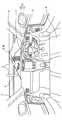
第一実施形態のHUD装置による虚像表示状態を示す正面図であり、
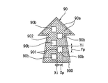
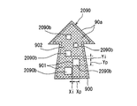
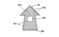
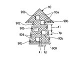
第一実施形態のHUD装置により虚像表示される報知画像を示す正面図であり、
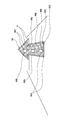
第一実施形態のHUD装置により虚像表示される報知画像の外界実像との重畳状態を示す正面図であり、
第二実施形態のHUD装置により虚像表示される報知画像を示す正面図であり、
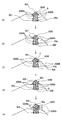
第三実施形態のHUD装置により虚像表示される報知画像の外界実像との重畳状態を時間経過毎に示す正面図であり、
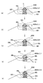
第四実施形態のHUD装置により虚像表示される報知画像の外界実像との重畳状態を時間経過毎に示す正面図であり、
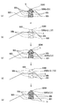
第五実施形態のHUD装置により虚像表示される報知画像の外界実像との重畳状態を時間経過毎に示す正面図であり、
図3の変形例を示す正面図であり、
図5の変形例を示す正面図であり、また
図6の変形例を示す正面図である。
以下、本開示の複数の実施形態を図面に基づいて説明する。尚、各実施形態において対応する構成要素には同一の符号を付すことにより、重複する説明を省略する場合がある。各実施形態において構成の一部分のみを説明している場合、当該構成の他の部分については、先行して説明した他の実施形態の構成を適用することができる。また、各実施形態の説明において明示している構成の組み合わせばかりではなく、特に組み合わせに支障が生じなければ、明示していなくても複数の実施形態の構成同士を部分的に組み合せることができる。
(第一実施形態)
図1に示すように、本開示の第一実施形態によるHUD装置1は、車両2に搭載されている。HUD装置1には、投影ユニット10及び表示制御ユニット20を備えている。尚、図1,2における上下方向及び横方向はそれぞれ、水平面上の車両2における鉛直方向及び水平方向と実質一致している。
図1に示すように、本開示の第一実施形態によるHUD装置1は、車両2に搭載されている。HUD装置1には、投影ユニット10及び表示制御ユニット20を備えている。尚、図1,2における上下方向及び横方向はそれぞれ、水平面上の車両2における鉛直方向及び水平方向と実質一致している。
投影ユニット10は、車両2内のうちインストルメントパネル3内に収容されている。投影ユニット10は、投射器11及び光学系12を有している。投射器11は、例えば液晶式又は走査式等のプロジェクタである。投射器11は、本実施形態ではカラーの表示画像9を形成して投射する。光学系12は、例えば反射鏡等といった光学部材の少なくとも1つから、構成されている。光学系12は、投射器11から投射された表示画像9の光束を、例えば反射等によりインストルメントパネル3外へと導く。
こうして光束が光学系12により図1の一点鎖線の如く導かれることで、表示画像9が車両2のフロントウィンドシールド4に投影される。ここで、「投影部材」として透光性ガラスから形成されるフロントウィンドシールド4は、投影された表示画像9の光束を反射すると共に、車両2外のうち前方に存在する外界実像5の光束を透過させる。
したがって、フロントウィンドシールド4で反射した表示画像9の光束と、フロントウィンドシールド4を透過した外界実像5の光束は、車両2内の運転席6上に着座した乗員7の瞳に入射する。その結果、車両2外のうちフロントウィンドシールド4よりも前方に結像されることとなる表示画像9の虚像は、外界実像5よりも運転席6側にて、乗員7により視認される。即ち本実施形態では、外界実像5の運転席6側に重畳する表示画像9が、乗員7により視認可能に虚像表示されるのである。
こうして虚像表示される表示画像9は、車両2内において所定情報を乗員7へと報知する報知機能を、果たす。表示画像9による報知情報としては、車速といった計器情報、制限速度標識といった交通標識情報、速度超過警告といった警告情報、電話又はメールに関するコミュニケーション情報、ターンバイターンといった経路情報等が、例えば挙げられる。ここで特に、交通法規の遵守に影響の少ない「特定情報」として、経路情報が採用されている。即ち本実施形態では、図2に示す如く経路情報を報知する表示画像9が、報知画像90として設定されているのである。
図1に示すように表示制御ユニット20は、車両2内のうちインストルメントパネル3内に、投影ユニット10と共に収容されている。表示制御ユニット20は、マイクロコンピュータ及び画像処理回路を主体に構成されている。表示制御ユニット20は、投影ユニット10のうち少なくとも投射器11と電気的に接続されている。それと共に表示制御ユニット20は、虚像表示に必要な電装品、例えば車両2の他の表示制御ユニット及びセンサ等と通信可能に接続されている。表示制御ユニット20は、接続された電装品からの信号に基づき、投影ユニット10を制御する。これにより表示制御ユニット20は、報知画像90を含む表示画像9の虚像表示状態を、調整する。
以下、表示制御ユニット20が投影ユニット10を制御することによる報知画像90の表示状態調整につき、詳細に説明する。表示制御ユニット20は、図3に示す如き通常画素90aと特定画素90bとにより、報知画像90を形成する。
通常画素90aは、報知画像90において図3にクロスハッチングを付して示した部分のうち一点鎖線よりも外側の外縁部分900として、外形形状の輪郭をなす所定数画素に設定される。それと共に通常画素90aは、報知画像90において図3にクロスハッチングを付して示した部分のうち一点鎖線よりも内側、即ち外縁部分900よりも内側の内側部分901として、特定画素90b以外の残部902をなす所定数画素にも設定される。
このように、報知画像90において外縁部分900と内側部分901のうち特定画素90b以外の残部902とを構成する通常画素90aには、図4に示す如く重畳する外界実像5に対して視認性を高めるコントラスト比が、付与される。そこで表示制御ユニット20は、例えばRGBの各階調値がいずれも最大値となるホワイト等といった比較的高輝度の色調をもって、通常画素90aを形成する。
一方で特定画素90bは、図3に白抜き四角形で示すように、報知画像90の内側部分901のうち通常画素90aの設定されない複数箇所にて、それぞれ所定数画素ずつに設定される。このように、報知画像90の内側部分901のうち複数箇所を構成する特定画素90bについては、図4に示す如く重畳する外界実像5を実質そのまま透過するように、虚像表示がカットされる。これにより報知画像90は、あたかも半透明であるかの如き視認性を、擬似的に実現する。そこで表示制御ユニット20は、例えばRGBの各階調値がいずれも最小値となる零輝度をもって、全箇所の特定画素90bを形成する。
ここで、報知画像90の内側部分901において特定画素90bの現出する複数箇所は、規則的な市松模様状に配置される。そこで表示制御ユニット20は、各箇所の特定画素90b毎に構成画素の配置形態に応じて決まる外形形状を、実質同一形状に調整する。それと共に表示制御ユニット20は、各箇所の特定画素90b毎に構成画素の配置数に応じて決まる横方向の外形サイズXp及び横方向の配置間隔Xiを、それぞれ実質一定寸法に調整する。また同様に表示制御ユニット20は、各箇所の特定画素90b毎に構成画素の配置数に応じて決まる上下方向の外形サイズYp及び上下方向の配置間隔Yiを、それぞれ実質一定寸法に調整する。以上を踏まえて特に本実施形態では、報知画像90の全面積に対して各箇所における特定画素90bの総面積が例えば20~70%程度の割合を占めるように、外形サイズXp,Yp同士が実質同一寸法の正方形状をもって、各箇所の特定画素90bが形成される。
以上説明した第一実施形態によると、車両2内の乗員7へ情報を報知するために外界実像5と重畳して虚像表示される報知画像90において、外縁部分900よりも内側部分901を構成する特定画素90bの虚像表示がカットされる。これにより報知画像90では、内側部分901のうち虚像表示のカットされる特定画素90bにて外界実像5を実質そのまま透過させると同時に、外縁部分900と内側部分901のうち特定画素90b以外とにて当該外界実像5に対する視認性の高いコントラスト比を付与し得る。故に、外界実像5の視認性と、報知画像90による情報の報知性とを、両立して確保することが可能となる。
また、第一実施形態によると、虚像表示のカットされる特定画素90bが報知画像90の内側部分901における複数箇所に現出することで、外界実像5が実質そのまま透過する箇所が増加する。故に、外界実像5の視認性を確実に確保しながら、当該外界実像5に対する視認性の高いコントラスト比を報知画像90の外縁部分900と内側部分901のうち特定画素90b以外とに付与して、情報の報知性をも確保することが可能となる。
さらに、第一実施形態によると、虚像表示のカットされる特定画素90bが現出する複数箇所は、報知画像90の内側部分901において市松模様状に配置される。こうした市松模様状という規則的な配置によれば、報知画像90を形成するための画像処理を簡素化して、当該報知画像90の虚像表示の応答性を高めることが可能となる。
(第二実施形態)
本開示の第二実施形態は、第一実施形態の変形例である。図5に白抜き四角形で示す第二実施形態の特定画素2090bについては、報知画像2090の内側部分901において現出する複数箇所が、ランダムに配置される。こうした第二実施形態では、各箇所の特定画素2090b毎に構成画素の配置形態に応じて決まる外形形状が、表示制御ユニット20により相似形状へと調整される。それと共に、各箇所の特定画素2090b毎に構成画素の配置数に応じて決まる横方向の外形サイズXp及び横方向の配置間隔Xiが、表示制御ユニット20によりそれぞれ相異なる寸法へと調整される。さらに、各箇所の特定画素2090b毎に構成画素の配置数に応じて決まる上下方向の外形サイズYp及び上下方向の配置間隔Yiが、表示制御ユニット20によりそれぞれ相異なる寸法へと調整される。尚、特定画素2090bについて以上説明した以外の内容は、第一実施形態で説明した特定画素90bについての内容と実質同一である。
本開示の第二実施形態は、第一実施形態の変形例である。図5に白抜き四角形で示す第二実施形態の特定画素2090bについては、報知画像2090の内側部分901において現出する複数箇所が、ランダムに配置される。こうした第二実施形態では、各箇所の特定画素2090b毎に構成画素の配置形態に応じて決まる外形形状が、表示制御ユニット20により相似形状へと調整される。それと共に、各箇所の特定画素2090b毎に構成画素の配置数に応じて決まる横方向の外形サイズXp及び横方向の配置間隔Xiが、表示制御ユニット20によりそれぞれ相異なる寸法へと調整される。さらに、各箇所の特定画素2090b毎に構成画素の配置数に応じて決まる上下方向の外形サイズYp及び上下方向の配置間隔Yiが、表示制御ユニット20によりそれぞれ相異なる寸法へと調整される。尚、特定画素2090bについて以上説明した以外の内容は、第一実施形態で説明した特定画素90bについての内容と実質同一である。
このような第二実施形態によると、虚像表示のカットされる特定画素2090bが現出する複数箇所は、報知画像2090の内側部分901においてランダムに配置される。こうしたランダム配置によれば、特定画素2090bが規則的に並ぶことに起因するモアレ等の視認性低下につき、抑制することが可能となる。しかも、特定画素2090bの現出する複数箇所のサイズが相異なることによれば、モアレ等の視認性低下を抑制する効果が高くなるのである。
(第三実施形態)
本開示の第三実施形態は、第一実施形態の変形例である。図6の時間経過毎の各分図に白抜き四角形で示す第三実施形態の特定画素3090bについては、報知画像3090の内側部分901において現出する複数箇所が、時間の経過に従って変位する。特に第三実施形態では、虚像表示状態の内側部分901において各箇所の特定画素3090bが下方から上方へと向かって変位することで、車両2の進行方向に向かって動くフレームアニメーションが実現される。
本開示の第三実施形態は、第一実施形態の変形例である。図6の時間経過毎の各分図に白抜き四角形で示す第三実施形態の特定画素3090bについては、報知画像3090の内側部分901において現出する複数箇所が、時間の経過に従って変位する。特に第三実施形態では、虚像表示状態の内側部分901において各箇所の特定画素3090bが下方から上方へと向かって変位することで、車両2の進行方向に向かって動くフレームアニメーションが実現される。
こうした第三実施形態では、フレーム毎に構成画素が下方から減少し且つ上方に増加する動画状に、各箇所の特定画素3090bが表示制御ユニット20により形成される。但し、内側部分901のうち図6(b),(d)に示す下方の外縁部分900との境界付近では、フレーム毎に構成画素が当該境界から上方に増加する動画状に、特定画素3090bが形成される。また一方、内側部分901のうち図6(a),(d),(e)に示す上方の外縁部分900との境界付近では、フレーム毎に構成画素が当該境界から下方に減少する動画状に、特定画素3090bが形成される。尚、特定画素3090bについて以上説明した以外の内容は、第一実施形態で説明した特定画素90bについての内容と実質同一である。
このような第三実施形態によると、虚像表示のカットされる特定画素3090bが現出する箇所は、報知画像3090の内側部分901において時間変位する。これによれば、外界実像5が実質そのまま透過する箇所として特定画素3090bの現出箇所が時間変位することになるので、報知画像3090による情報の報知性を確保しながら、図6の各分図に示す外界実像5の判別性を高めることが可能となる。
(第四実施形態)
本開示の第四実施形態は、第一実施形態の変形例である。図7の時間経過毎の各分図にクロスハッチングの線間隔を変えて示す第四実施形態の報知画像4090については、通常画素4090aにおける虚像表示輝度の高低が繰り返される。特に第四実施形態では、高輝度側の通常輝度Lhと、それよりも低輝度側の変更輝度Llとの間にて、通常画素4090aの虚像表示輝度を交互に切り替えるフレームアニメーションが実現される。ここで、高輝度時のフレーム数と低輝度時のフレーム数との比は、乗員7が視認時にちらつきを感じるのを抑制するように、例えば1:1、2:1、又は3:1等に設定される。
本開示の第四実施形態は、第一実施形態の変形例である。図7の時間経過毎の各分図にクロスハッチングの線間隔を変えて示す第四実施形態の報知画像4090については、通常画素4090aにおける虚像表示輝度の高低が繰り返される。特に第四実施形態では、高輝度側の通常輝度Lhと、それよりも低輝度側の変更輝度Llとの間にて、通常画素4090aの虚像表示輝度を交互に切り替えるフレームアニメーションが実現される。ここで、高輝度時のフレーム数と低輝度時のフレーム数との比は、乗員7が視認時にちらつきを感じるのを抑制するように、例えば1:1、2:1、又は3:1等に設定される。
こうした第四実施形態では、外界実像5に対して視認性の高いコントラスト比が付与されるように、例えばRGBの各階調値がいずれも最大値となるホワイト等といった通常輝度Lhの色調をもって、図7(a),(c),(e)に示す高輝度時の通常画素4090aが表示制御ユニット20により形成される。また一方、特定画素90bを透過した部分の隣接箇所にて重畳する外界実像5の視認を許容するように、例えばRGBの各階調値がいずれも中間値となるグレー等といった変更輝度Llの色調をもって、図7(b),(d)に示す低輝度時の通常画素4090aが表示制御ユニット20により形成される。尚、通常画素4090aについて以上説明した以外の内容は、第一実施形態で説明した通常画素90aについての内容と実質同一である。
このような第四実施形態によると、報知画像4090において外縁部分900と内側部分901のうち特定画素90b以外とを構成する通常画素4090aに対して、虚像表示輝度の高低が繰り返される。ここで、虚像表示輝度が高くなった高輝度時の通常画素4090aには、特定画素90bを実質そのまま透過した外界実像5に対して、視認性の高いコントラスト比を付与し得る。また一方で、通常画素4090aの虚像表示輝度が低い低輝度時には、特定画素90bを実質そのまま透過する部分に隣接して当該通常画素4090aと重畳する部分の外界実像5が、図7(b),(d)に示す如く視認され得る。以上によれば、報知画像4090による情報の報知性を高輝度時の通常画素4090aにより維持しつつも、常にカットされる特定画素90bと低輝度時の通常画素4090aとにより外界実像5の視認性を高めることが、可能となる。
(第五実施形態)
本開示の第五実施形態は、第四実施形態の変形例である。図8の時間経過毎の各分図を示す第五実施形態の報知画像5090については、第四実施形態と同様に虚像表示輝度の高低が通常画素5090aにおいて繰り返されるが、低輝度側の変更輝度Llが零輝度L0となる。その結果として低輝度時の通常画素5090aは、特定画素90bと共に虚像表示のカットされた状態となるので、報知画像5090の全体として間欠的に消えるフレームアニメーションが実現される。尚、図8(b),(d)は、通常画素5090a及び特定画素90bの虚像表示がカットされた状態を、二点鎖線により擬似的に示している。
本開示の第五実施形態は、第四実施形態の変形例である。図8の時間経過毎の各分図を示す第五実施形態の報知画像5090については、第四実施形態と同様に虚像表示輝度の高低が通常画素5090aにおいて繰り返されるが、低輝度側の変更輝度Llが零輝度L0となる。その結果として低輝度時の通常画素5090aは、特定画素90bと共に虚像表示のカットされた状態となるので、報知画像5090の全体として間欠的に消えるフレームアニメーションが実現される。尚、図8(b),(d)は、通常画素5090a及び特定画素90bの虚像表示がカットされた状態を、二点鎖線により擬似的に示している。
こうした第五実施形態では、特定画素90bを透過した部分の隣接箇所でも重畳する外界実像5の透過を許容するように、例えばRGBの各階調値がいずれも最小値となる零輝度L0をもって、図8(b),(d)に示す低輝度時の通常画素5090aが表示制御ユニット20により形成される。尚、図8(a),(c),(e)に示すように高輝度時の通常画素5090aは、第四実施形態と同様な通常輝度Lhの色調をもって、表示制御ユニット20により形成される。また、通常画素5090aについて以上説明した以外の内容は、第一実施形態で説明した通常画素90aについての内容と実質同一である。
このような第五実施形態によると、報知画像5090において通常画素5090aの虚像表示輝度は、高輝度側の通常輝度Lhと、それよりも低輝度側の変更輝度Llである零輝度L0との間にて、交互に切り替えられる。ここで、虚像表示輝度が通常輝度Lhへと切り替えられた高輝度時の通常画素5090aには、特定画素90bを実質そのまま透過した外界実像5に対して、視認性の高いコントラスト比を付与し得る。また一方で、虚像表示輝度が低輝度側の零輝度L0へと切り替えられることで虚像表示がカットされることとなる低輝度時の通常画素5090aでは、特定画素90bと同様に、図8(b),(d)に示す如く外界実像5が実質そのまま透過して視認され得る。以上によれば、報知画像5090による情報の報知性を高輝度時の通常画素5090aにより維持しつつも、常にカットされる特定画素90bと低輝度時の通常画素5090aとにより外界実像5の視認性を確実に高めることが、可能となる。
(他の実施形態)
以上、本開示の複数の実施形態について説明したが、本開示は、それらの実施形態に限定して解釈されるものではなく、本開示の要旨を逸脱しない範囲内において種々の実施形態及び組み合わせに適用することができる。
以上、本開示の複数の実施形態について説明したが、本開示は、それらの実施形態に限定して解釈されるものではなく、本開示の要旨を逸脱しない範囲内において種々の実施形態及び組み合わせに適用することができる。
第一及び第三~第五実施形態に関する変形例1としては、図9に示すように、報知画像90,3090,4090,5090における特定画素90b,3090bを、一箇所にだけ形成してもよい。尚、図9は、第一実施形態の変形例1を代表して示している。
第二実施形態に関する変形例2としては、図10に示すように、報知画像2090における複数箇所の特定画素2090bを、上下方向及び横方向のそれぞれで外形サイズXp,Ypが実質一定となるように調整して、ランダムに配置してもよい。かかる変形例2では、上下方向及び横方向のそれぞれで配置間隔Xi,Yiが相異ならされる。
第一~第五実施形態に関する変形例3としては、報知画像90,2090,3090,4090,5090における特定画素90b,2090b、3090bを、例えば図11に示す長方形状等、正方形以外の形状に形成してもよい。尚、図11は、第三実施形態の変形例3を代表して示している。
第二実施形態に関する変形例4としては、第三実施形態に準じたフレームアニメーションを、組み合わせて実現してもよい。第二実施形態に関する変形例5としては、第四及び第五実施形態のうち一方に準じたフレームアニメーションを、組み合わせて実現してもよい。第三実施形態に関する変形例6としては、第四及び第五実施形態のうち一方に準じたフレームアニメーションも、組み合わせて実現してもよい。
第一~第五実施形態に関する変形例7としては、第一実施形態にて例示した計器情報、交通標識情報、警告情報及びコミュニケーション情報のうちいずれかを、報知画像90,2090,3090,4090,5090により報知する「特定情報」としてもよい。第一~第五実施形態に関する変形例8としては、車両2内においてフロントウィンドシールド4よりも運転席6側に配置される透光性のコンバイナを、「投影部材」としてもよい。
上述の第一開示によるヘッドアップディスプレイ装置1は、車両2において外界実像5を透過する投影部材4へ表示画像9を投影することにより、外界実像と重畳する表示画像を車両内の乗員7により視認可能に虚像表示する。ヘッドアップディスプレイ装置1は、投影ユニット10と、表示制御ユニットとを、備える。投影ユニット10は、乗員へ特定情報を報知する表示画像としての報知画像90,2090,3090,4090,5090を、投影部材へ投影する。表示制御ユニットとは、投影ユニットを制御することにより、表示画像の虚像表示状態を調整する表示制御ユニット20として、報知画像において外縁部分900よりも内側部分901を構成する特定画素90b,2090b,3090bの虚像表示をカットする。
このような第一開示によると、車両内の乗員へ情報を報知するために外界実像と重畳して虚像表示される報知画像において、外縁部分よりも内側部分を構成する特定画素の虚像表示がカットされる。これにより報知画像では、内側部分のうち虚像表示のカットされる特定画素にて外界実像を実質そのまま透過させると同時に、外縁部分と内側部分のうち特定画素以外とにて当該外界実像に対する視認性の高いコントラスト比を付与し得る。故に、外界実像の視認性と、報知画像による情報の報知性とを、両立して確保することが可能となる。
また、開示された第二開示によると、表示制御ユニットは、報知画像の内側部分における複数箇所に特定画素を現出させる。
このような第二開示によると、虚像表示のカットされる特定画素が報知画像の内側部分における複数箇所に現出することで、外界実像が実質そのまま透過する箇所が増加する。故に、外界実像の視認性を確実に確保しながら、当該外界実像に対する視認性の高いコントラスト比を報知画像の外縁部分と内側部分のうち特定画素以外とに付与して、情報の報知性をも確保することが可能となる。
本開示は、実施例に準拠して記述されたが、本開示は当該実施例や構造に限定されるものではないと理解される。本開示は、様々な変形例や均等範囲内の変形をも包含する。加えて、様々な組み合わせや形態、さらには、それらに一要素のみ、それ以上、あるいはそれ以下、を含む他の組み合わせや形態をも、本開示の範疇や思想範囲に入るものである。
Claims (8)
- 車両(2)において外界実像(5)を透過する投影部材(4)へ表示画像(9)を投影することにより、前記外界実像(5)と重畳する前記表示画像(9)を前記車両内の乗員(7)により視認可能に虚像表示するヘッドアップディスプレイ装置であって、
前記乗員(7)へ特定情報を報知する前記表示画像(9)としての報知画像(90,2090,3090,4090,5090)を、前記投影部材(4)へ投影する投影ユニット(10)と、
前記投影ユニット(10)を制御することにより、前記表示画像(9)の虚像表示状態を調整し、前記報知画像(90,2090,3090,4090,5090)において外縁部分(900)よりも内側部分(901)を構成する特定画素(90b,2090b,3090b)の虚像表示をカットする表示制御ユニット(20)とを、備えるヘッドアップディスプレイ装置。 - 前記表示制御ユニット(20)は、
前記報知画像(90,2090,3090,4090,5090)の前記内側部分(901)における複数箇所に前記特定画素(90b,2090b,3090b)を現出させる請求項1に記載のヘッドアップディスプレイ装置。 - 前記表示制御ユニット(20)は、
前記特定画素(90b)を現出させる前記複数箇所を、前記報知画像(90)の前記内側部分(901)において市松模様状に配置する請求項2に記載のヘッドアップディスプレイ装置。 - 前記表示制御ユニット(20)は、
前記特定画素(2090b)を現出させる前記複数箇所を、前記報知画像(2090)の前記内側部分(901)においてランダムに配置する請求項2に記載のヘッドアップディスプレイ装置。 - 前記表示制御ユニット(20)は、
前記特定画素(90b,2090b,3090b)を現出させる前記複数箇所のサイズを、相異ならせる請求項4に記載のヘッドアップディスプレイ装置。 - 前記表示制御ユニット(20)は、
前記特定画素(3090b)を現出させる箇所を、前記報知画像(3090)の前記内側部分(901)において時間変位させる請求項1~5のいずれか一項に記載のヘッドアップディスプレイ装置。 - 前記表示制御ユニット(20)は、
前記報知画像(4090,5090)において前記外縁部分(900)と前記内側部分(901)のうち前記特定画素(90b,2090b,3090b)以外とを構成する通常画素(4090a,5090a)に対して、虚像表示輝度の高低を繰り返す請求項1~6のいずれか一項に記載のヘッドアップディスプレイ装置。 - 前記表示制御ユニット(20)は、
高輝度側の通常輝度(Lh)と、前記通常輝度よりも低輝度側の零輝度(L0)との間にて、交互に前記通常画素(5090a)の虚像表示輝度を切り替える請求項7に記載のヘッドアップディスプレイ装置。
Priority Applications (4)
| Application Number | Priority Date | Filing Date | Title |
|---|---|---|---|
| US16/080,685 US10859820B2 (en) | 2016-03-02 | 2017-01-27 | Head-up display device |
| CN201780014163.7A CN108780630B (zh) | 2016-03-02 | 2017-01-27 | 平视显示器装置 |
| DE112017001091.8T DE112017001091T5 (de) | 2016-03-02 | 2017-01-27 | Head-up-anzeigevorrichtung |
| KR1020187027833A KR102093685B1 (ko) | 2016-03-02 | 2017-01-27 | 헤드업 디스플레이 장치 |
Applications Claiming Priority (2)
| Application Number | Priority Date | Filing Date | Title |
|---|---|---|---|
| JP2016040331A JP6551263B2 (ja) | 2016-03-02 | 2016-03-02 | ヘッドアップディスプレイ装置 |
| JP2016-040331 | 2016-03-02 |
Publications (1)
| Publication Number | Publication Date |
|---|---|
| WO2017150025A1 true WO2017150025A1 (ja) | 2017-09-08 |
Family
ID=59742738
Family Applications (1)
| Application Number | Title | Priority Date | Filing Date |
|---|---|---|---|
| PCT/JP2017/002843 Ceased WO2017150025A1 (ja) | 2016-03-02 | 2017-01-27 | ヘッドアップディスプレイ装置 |
Country Status (6)
| Country | Link |
|---|---|
| US (1) | US10859820B2 (ja) |
| JP (1) | JP6551263B2 (ja) |
| KR (1) | KR102093685B1 (ja) |
| CN (1) | CN108780630B (ja) |
| DE (1) | DE112017001091T5 (ja) |
| WO (1) | WO2017150025A1 (ja) |
Families Citing this family (3)
| Publication number | Priority date | Publication date | Assignee | Title |
|---|---|---|---|---|
| DE112016007015T5 (de) * | 2016-07-29 | 2019-03-21 | Mitsubishi Electric Corporation | Anzeigevorrichtung, anzeigesteuervorrichtung und anzeigesteuerverfahren |
| KR102856578B1 (ko) * | 2022-02-11 | 2025-09-08 | 한국광기술원 | 현실감을 향상시키고 광원과 광학계가 일체화된 증강현실 장치 |
| CN115857168B (zh) * | 2022-12-16 | 2025-06-27 | 浙江炽云科技有限公司 | 导航信息的显示方法、抬头显示装置、载具及存储介质 |
Citations (4)
| Publication number | Priority date | Publication date | Assignee | Title |
|---|---|---|---|---|
| JP2008136690A (ja) * | 2006-12-01 | 2008-06-19 | Sankyo Co Ltd | スロットマシン |
| EP2221654A1 (en) * | 2009-02-19 | 2010-08-25 | Thomson Licensing | Head mounted display |
| JP2015068831A (ja) * | 2013-09-30 | 2015-04-13 | 本田技研工業株式会社 | 機能拡張された3次元(3−d)ナビゲーション |
| JP2015096946A (ja) * | 2013-10-10 | 2015-05-21 | パナソニックIpマネジメント株式会社 | 表示制御装置、表示制御プログラム、および表示制御方法 |
Family Cites Families (25)
| Publication number | Priority date | Publication date | Assignee | Title |
|---|---|---|---|---|
| JP3125367B2 (ja) * | 1991-09-21 | 2001-01-15 | 日産自動車株式会社 | 車両用スイッチ装置 |
| JPH08235376A (ja) * | 1995-02-22 | 1996-09-13 | Hitachi Ltd | 図形編集装置 |
| JPH0935177A (ja) | 1995-07-18 | 1997-02-07 | Hitachi Ltd | 運転支援方法および運転支援装置 |
| US7561966B2 (en) * | 2003-12-17 | 2009-07-14 | Denso Corporation | Vehicle information display system |
| US7403639B2 (en) * | 2004-11-30 | 2008-07-22 | Honda Motor Co., Ltd. | Vehicle surroundings monitoring apparatus |
| JP2006284458A (ja) | 2005-04-01 | 2006-10-19 | Denso Corp | 運転支援情報表示システム |
| US20130273005A1 (en) | 2010-12-20 | 2013-10-17 | Gilead Sciences, Inc. | Methods for treating hcv |
| JP5842419B2 (ja) * | 2011-07-06 | 2016-01-13 | 日本精機株式会社 | ヘッドアップディスプレイ装置 |
| JP5197881B1 (ja) | 2011-09-30 | 2013-05-15 | パイオニア株式会社 | ヘッドアップディスプレイ、制御方法、及び表示装置 |
| JP4975889B1 (ja) | 2012-02-07 | 2012-07-11 | パイオニア株式会社 | ヘッドアップディスプレイ、制御方法、及び表示装置 |
| JP6027878B2 (ja) * | 2012-12-12 | 2016-11-16 | 矢崎総業株式会社 | 複合表示装置 |
| US20140176425A1 (en) * | 2012-12-20 | 2014-06-26 | Sl Corporation | System and method for identifying position of head-up display area |
| US20140240204A1 (en) * | 2013-02-22 | 2014-08-28 | E-Lead Electronic Co., Ltd. | Head-up display device for a smart phone |
| US9164281B2 (en) * | 2013-03-15 | 2015-10-20 | Honda Motor Co., Ltd. | Volumetric heads-up display with dynamic focal plane |
| US9064420B2 (en) | 2013-03-14 | 2015-06-23 | Honda Motor Co., Ltd. | Augmented reality heads up display (HUD) for yield to pedestrian safety cues |
| US20160054563A9 (en) * | 2013-03-14 | 2016-02-25 | Honda Motor Co., Ltd. | 3-dimensional (3-d) navigation |
| US9392129B2 (en) * | 2013-03-15 | 2016-07-12 | John Castle Simmons | Light management for image and data control |
| US20140362195A1 (en) | 2013-03-15 | 2014-12-11 | Honda Motor, Co., Ltd. | Enhanced 3-dimensional (3-d) navigation |
| JP6044838B2 (ja) * | 2013-04-04 | 2016-12-14 | 日本精機株式会社 | ヘッドアップディスプレイ装置 |
| FR3005361B1 (fr) * | 2013-05-06 | 2018-05-04 | Dassault Aviation | Dispositif d'aide au pilotage propre a afficher une animation et procede associe |
| JP6149543B2 (ja) * | 2013-06-28 | 2017-06-21 | アイシン・エィ・ダブリュ株式会社 | ヘッドアップディスプレイ装置 |
| JP6225379B2 (ja) | 2013-12-23 | 2017-11-08 | 日本精機株式会社 | 車両情報投影システム |
| KR101572065B1 (ko) * | 2014-01-03 | 2015-11-25 | 현대모비스(주) | 영상 왜곡 보정 방법 및 이를 위한 장치 |
| JP6287351B2 (ja) | 2014-03-04 | 2018-03-07 | アイシン・エィ・ダブリュ株式会社 | ヘッドアップディスプレイ装置 |
| JP6550716B2 (ja) * | 2014-10-16 | 2019-07-31 | 日本精機株式会社 | ヘッドアップディスプレイ装置 |
-
2016
- 2016-03-02 JP JP2016040331A patent/JP6551263B2/ja not_active Expired - Fee Related
-
2017
- 2017-01-27 DE DE112017001091.8T patent/DE112017001091T5/de active Pending
- 2017-01-27 US US16/080,685 patent/US10859820B2/en not_active Expired - Fee Related
- 2017-01-27 KR KR1020187027833A patent/KR102093685B1/ko not_active Expired - Fee Related
- 2017-01-27 WO PCT/JP2017/002843 patent/WO2017150025A1/ja not_active Ceased
- 2017-01-27 CN CN201780014163.7A patent/CN108780630B/zh not_active Expired - Fee Related
Patent Citations (4)
| Publication number | Priority date | Publication date | Assignee | Title |
|---|---|---|---|---|
| JP2008136690A (ja) * | 2006-12-01 | 2008-06-19 | Sankyo Co Ltd | スロットマシン |
| EP2221654A1 (en) * | 2009-02-19 | 2010-08-25 | Thomson Licensing | Head mounted display |
| JP2015068831A (ja) * | 2013-09-30 | 2015-04-13 | 本田技研工業株式会社 | 機能拡張された3次元(3−d)ナビゲーション |
| JP2015096946A (ja) * | 2013-10-10 | 2015-05-21 | パナソニックIpマネジメント株式会社 | 表示制御装置、表示制御プログラム、および表示制御方法 |
Also Published As
| Publication number | Publication date |
|---|---|
| US10859820B2 (en) | 2020-12-08 |
| JP6551263B2 (ja) | 2019-07-31 |
| DE112017001091T5 (de) | 2018-11-29 |
| CN108780630B (zh) | 2020-12-22 |
| KR102093685B1 (ko) | 2020-03-26 |
| US20190064514A1 (en) | 2019-02-28 |
| CN108780630A (zh) | 2018-11-09 |
| JP2017156580A (ja) | 2017-09-07 |
| KR20180117662A (ko) | 2018-10-29 |
Similar Documents
| Publication | Publication Date | Title |
|---|---|---|
| EP2511750A1 (en) | Vehicular information display system | |
| KR20180103947A (ko) | 정보 표시 장치 | |
| JP6671942B2 (ja) | ヘッドアップディスプレイ装置 | |
| JP6551263B2 (ja) | ヘッドアップディスプレイ装置 | |
| JP6052050B2 (ja) | ヘッドアップディスプレイ装置 | |
| JP2017190056A (ja) | ヘッドアップディスプレイ装置 | |
| JP6780960B2 (ja) | 画像表示装置 | |
| JP6287333B2 (ja) | ヘッドアップディスプレイ装置 | |
| JP2018189956A (ja) | スクリーンシステム、表示システム、スクリーンシステムの制御方法、プログラム、及び表示システムを備える移動体 | |
| JP5900447B2 (ja) | 車両用表示装置 | |
| JP2023147782A (ja) | 表示システム | |
| WO2021166878A1 (ja) | ナビゲーション装置、ナビゲーション装置の制御方法、ナビゲーション装置の制御プログラム | |
| JP2020168985A (ja) | 車両用表示装置 | |
| JP7495584B1 (ja) | 虚像表示装置、移動体、虚像表示装置の駆動方法、及びプログラム | |
| JP6160512B2 (ja) | ヘッドアップディスプレイ装置 | |
| WO2020085159A1 (ja) | 表示装置 | |
| JP2019028328A (ja) | 光提示装置 | |
| JP7760838B2 (ja) | 表示制御装置、表示装置、及び表示制御方法 | |
| JP2025099071A (ja) | 車両用表示装置 | |
| JP2023015543A (ja) | 表示装置 | |
| WO2024127923A1 (ja) | 虚像表示装置 | |
| JP2015160570A (ja) | ヘッドアップディスプレイ装置 | |
| JP2025012233A (ja) | ヘッドアップディスプレイ装置 | |
| JP2023005350A (ja) | 表示装置 | |
| WO2025088992A1 (ja) | 虚像表示装置及び虚像表示方法 |
Legal Events
| Date | Code | Title | Description |
|---|---|---|---|
| ENP | Entry into the national phase |
Ref document number: 20187027833 Country of ref document: KR Kind code of ref document: A |
|
| 121 | Ep: the epo has been informed by wipo that ep was designated in this application |
Ref document number: 17759497 Country of ref document: EP Kind code of ref document: A1 |
|
| 122 | Ep: pct application non-entry in european phase |
Ref document number: 17759497 Country of ref document: EP Kind code of ref document: A1 |