WO2017149928A1 - Appareil d'imagerie ophtalmologique - Google Patents
Appareil d'imagerie ophtalmologique Download PDFInfo
- Publication number
- WO2017149928A1 WO2017149928A1 PCT/JP2017/000310 JP2017000310W WO2017149928A1 WO 2017149928 A1 WO2017149928 A1 WO 2017149928A1 JP 2017000310 W JP2017000310 W JP 2017000310W WO 2017149928 A1 WO2017149928 A1 WO 2017149928A1
- Authority
- WO
- WIPO (PCT)
- Prior art keywords
- abnormality
- unit
- scan
- detection unit
- series
- Prior art date
Links
Images


Classifications
-
- A—HUMAN NECESSITIES
- A61—MEDICAL OR VETERINARY SCIENCE; HYGIENE
- A61B—DIAGNOSIS; SURGERY; IDENTIFICATION
- A61B3/00—Apparatus for testing the eyes; Instruments for examining the eyes
- A61B3/10—Objective types, i.e. instruments for examining the eyes independent of the patients' perceptions or reactions
- A61B3/14—Arrangements specially adapted for eye photography
-
- A—HUMAN NECESSITIES
- A61—MEDICAL OR VETERINARY SCIENCE; HYGIENE
- A61B—DIAGNOSIS; SURGERY; IDENTIFICATION
- A61B3/00—Apparatus for testing the eyes; Instruments for examining the eyes
- A61B3/0016—Operational features thereof
- A61B3/0025—Operational features thereof characterised by electronic signal processing, e.g. eye models
-
- A—HUMAN NECESSITIES
- A61—MEDICAL OR VETERINARY SCIENCE; HYGIENE
- A61B—DIAGNOSIS; SURGERY; IDENTIFICATION
- A61B3/00—Apparatus for testing the eyes; Instruments for examining the eyes
- A61B3/10—Objective types, i.e. instruments for examining the eyes independent of the patients' perceptions or reactions
- A61B3/102—Objective types, i.e. instruments for examining the eyes independent of the patients' perceptions or reactions for optical coherence tomography [OCT]
-
- A—HUMAN NECESSITIES
- A61—MEDICAL OR VETERINARY SCIENCE; HYGIENE
- A61B—DIAGNOSIS; SURGERY; IDENTIFICATION
- A61B3/00—Apparatus for testing the eyes; Instruments for examining the eyes
- A61B3/10—Objective types, i.e. instruments for examining the eyes independent of the patients' perceptions or reactions
- A61B3/113—Objective types, i.e. instruments for examining the eyes independent of the patients' perceptions or reactions for determining or recording eye movement
-
- G—PHYSICS
- G06—COMPUTING; CALCULATING OR COUNTING
- G06T—IMAGE DATA PROCESSING OR GENERATION, IN GENERAL
- G06T7/00—Image analysis
- G06T7/0002—Inspection of images, e.g. flaw detection
- G06T7/0012—Biomedical image inspection
-
- G—PHYSICS
- G06—COMPUTING; CALCULATING OR COUNTING
- G06T—IMAGE DATA PROCESSING OR GENERATION, IN GENERAL
- G06T2207/00—Indexing scheme for image analysis or image enhancement
- G06T2207/10—Image acquisition modality
- G06T2207/10072—Tomographic images
- G06T2207/10101—Optical tomography; Optical coherence tomography [OCT]
-
- G—PHYSICS
- G06—COMPUTING; CALCULATING OR COUNTING
- G06T—IMAGE DATA PROCESSING OR GENERATION, IN GENERAL
- G06T2207/00—Indexing scheme for image analysis or image enhancement
- G06T2207/30—Subject of image; Context of image processing
- G06T2207/30004—Biomedical image processing
- G06T2207/30041—Eye; Retina; Ophthalmic
Definitions
- the present invention relates to an ophthalmologic photographing apparatus that images an eye to be examined using optical coherence tomography (OCT).
- OCT optical coherence tomography
- Diagnostic imaging occupies an important position in the ophthalmology field.
- OCT has been used not only for acquiring B-mode images and three-dimensional images of the eye to be examined, but also for acquiring front images (en-face images) such as C-mode images and shadowgrams.
- part of the eye to be examined, and acquiring functional information are also performed.
- an image (angiogram) in which retinal blood vessels and choroidal blood vessels are emphasized can be constructed based on time-series data collected by OCT.
- blood flow information blood flow velocity, blood flow volume, etc.
- Such an imaging technique is disclosed in, for example, Patent Documents 1-3.
- a technique is also known in which a plurality of images are acquired by repeatedly scanning the same cross section, and these are averaged to create a low noise image (see, for example, Patent Document 4).
- Tracking is a technique for monitoring the movement of an eye to be examined during scanning with a video camera and controlling the optical scanner in real time according to the movement (see, for example, Patent Document 5).
- the rescan is a technique of monitoring the eye under examination with a video camera and rescanning the scanned position at the timing when the eye to be moved largely or the timing of blinking (see, for example, Patent Document 6). .
- the video from the video camera is analyzed to detect movement and blinking of the eye to be examined.
- the repetition rate of OCT scans for example, the repetition rate of B scans
- the frame rate of the video camera is about 20 to 50 FPS (frame interval about 20 to 50 ms).
- FPS frame interval about 20 to 50 ms
- An object of the present invention is to provide an ophthalmologic imaging apparatus capable of acquiring a highly accurate OCT image even when a subject's eye moves or blinks.
- the ophthalmic imaging apparatus includes a data collection unit, an imaging unit, a control unit, and an abnormality detection unit.
- the data collection unit collects data by scanning the eye to be examined using optical coherence tomography.
- the imaging unit captures the eye to be examined and acquires a front image.
- the control unit controls the data collection unit to perform a series of scans along a preset route group.
- the abnormality detection unit detects an abnormality based on a series of data collected by a series of scans and two or more front images including one or more front images acquired by the imaging unit corresponding to the series of scans. To do.
- the ophthalmologic photographing apparatus it is possible to acquire a highly accurate OCT image even when the eye to be examined moves or blinks.
- Schematic showing the example of a structure of the ophthalmologic imaging device which concerns on embodiment Schematic showing the example of a structure of the ophthalmologic imaging device which concerns on embodiment. Schematic showing the example of a structure of the ophthalmologic imaging device which concerns on embodiment. Schematic showing the example of a structure of the ophthalmologic imaging device which concerns on embodiment. Schematic showing the example of operation
- the embodiment is an ophthalmologic photographing apparatus having a function as an optical coherence tomography (OCT) and a function of acquiring a front image of an eye to be examined.
- OCT optical coherence tomography
- the latter function can be realized by, for example, a fundus camera, a scanning laser ophthalmoscope (SLO), a slit lamp microscope, an ophthalmic surgical microscope, an anterior ocular segment imaging camera, or the like.
- SLO scanning laser ophthalmoscope
- a slit lamp microscope an ophthalmic surgical microscope
- anterior ocular segment imaging camera or the like.
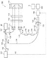
- the ophthalmologic photographing apparatus 1 includes a fundus camera unit 2, an OCT unit 100, and an arithmetic control unit 200.
- the fundus camera unit 2 is provided with an optical system and a mechanism for acquiring a front image of the eye to be examined.
- the OCT unit 100 is provided with an optical system and a mechanism for performing OCT.
- the arithmetic control unit 200 includes a processor that executes various arithmetic operations and controls. In addition to these, a member for supporting the subject's face (chin rest, forehead rest, etc.) and a lens unit (for example, an anterior ocular segment OCT attachment) for switching an OCT target site may be provided. Good.
- the “processor” is, for example, a CPU (Central Processing Unit), a GPU (Graphics Processing Unit), an ASIC (Application Specific Integrated Circuit), a programmable logic device (eg, SPLD (Simple ProGLD). It means a circuit such as Programmable Logic Device (FPGA) or Field Programmable Gate Array (FPGA).
- the processor implements the functions according to the embodiment by reading and executing a program stored in a storage circuit or a storage device.
- the fundus camera unit 2 is provided with an optical system for photographing the fundus oculi Ef of the eye E to be examined.
- the acquired image of the fundus oculi Ef (referred to as a fundus oculi image, a fundus oculi photo, or the like) is a front image such as an observation image or a captured image.
- the observation image is obtained by moving image shooting using near infrared light.
- the photographed image is a still image using flash light.
- the fundus camera unit 2 includes an illumination optical system 10 and a photographing optical system 30.
- the illumination optical system 10 irradiates the eye E with illumination light.
- the imaging optical system 30 detects the return light of the illumination light from the eye E.
- the measurement light from the OCT unit 100 is guided to the eye E through the optical path in the fundus camera unit 2, and the return light is guided to the OCT unit 100 through the same optical path.
- the light (observation illumination light) output from the observation light source 11 of the illumination optical system 10 is reflected by the reflection mirror 12 having a curved reflecting surface, passes through the condensing lens 13 and passes through the visible cut filter 14. Near infrared light. Further, the observation illumination light is once converged in the vicinity of the photographing light source 15, reflected by the mirror 16, and passes through the relay lenses 17 and 18, the diaphragm 19 and the relay lens 20. The observation illumination light is reflected by the peripheral part of the perforated mirror 21 (area around the perforated part), passes through the dichroic mirror 46, and is refracted by the objective lens 22 to be examined eye E (fundus Ef or anterior eye). Part).
- the return light of the observation illumination light from the eye E is refracted by the objective lens 22, passes through the dichroic mirror 46, passes through the hole formed in the central region of the perforated mirror 21, and passes through the dichroic mirror 55.
- the light is reflected by the mirror 32 via the photographing focusing lens 31. Further, the return light passes through the half mirror 33A, is reflected by the dichroic mirror 33, and forms an image on the light receiving surface of the image sensor 35 by the condenser lens.
- the image sensor 35 detects return light at a predetermined frame rate. Note that the focus of the photographing optical system 30 is adjusted with respect to the fundus oculi Ef or the anterior eye segment.
- the light (imaging illumination light) output from the imaging light source 15 is irradiated onto the fundus oculi Ef through the same path as the observation illumination light.
- the return light of the imaging illumination light from the eye E is guided to the dichroic mirror 33 through the same path as the return light of the observation illumination light, passes through the dichroic mirror 33, is reflected by the mirror 36, and is reflected by the condenser lens 37.
- An image is formed on the light receiving surface of the image sensor 38.
- LCD39 displays a fixation target and a visual target for visual acuity measurement.
- a part of the light beam output from the LCD 39 is reflected by the half mirror 33 ⁇ / b> A, reflected by the mirror 32, passes through the hole of the perforated mirror 21 through the photographing focusing lens 31 and the dichroic mirror 55.
- the fixation light beam that has passed through the hole of the aperture mirror 21 passes through the dichroic mirror 46, is refracted by the objective lens 22, and is projected onto the fundus oculi Ef.
- the alignment optical system 50 generates an alignment index used for alignment of the optical system with respect to the eye E.
- the alignment light output from the LED 51 passes through the apertures 52 and 53 and the relay lens 54, is reflected by the dichroic mirror 55, and passes through the hole of the perforated mirror 21.
- the light that has passed through the hole of the perforated mirror 21 passes through the dichroic mirror 46 and is projected onto the eye E by the objective lens 22.
- the corneal reflection light of the alignment light is guided to the image sensor 35 through the same path as the return light of the observation illumination light.
- Manual alignment and auto-alignment can be executed based on the received light image (alignment index image).
- the focus optical system 60 generates a split index used for focus adjustment on the eye E.
- the focus optical system 60 is moved along the optical path (illumination optical path) of the illumination optical system 10 in conjunction with the movement of the imaging focusing lens 31 along the optical path (imaging optical path) of the imaging optical system 30.
- the reflection bar 67 can be inserted into and removed from the illumination optical path.
- the reflecting surface of the reflecting bar 67 is inclinedly arranged in the illumination optical path.
- the focus light output from the LED 61 passes through the relay lens 62, is separated into two light beams by the split indicator plate 63, passes through the two-hole aperture 64, is reflected by the mirror 65, and is reflected by the condenser lens 66 as a reflecting rod 67.
- the light is once imaged and reflected on the reflection surface. Further, the focus light passes through the relay lens 20, is reflected by the perforated mirror 21, passes through the dichroic mirror 46, is refracted by the objective lens 22, and is projected onto the fundus oculi Ef.
- the fundus reflected light of the focus light is guided to the image sensor 35 through the same path as the cornea reflected light of the alignment light. Manual alignment and auto alignment can be executed based on the received light image (split index image).
- the diopter correction lenses 70 and 71 can be selectively inserted into the photographing optical path between the perforated mirror 21 and the dichroic mirror 55.
- the diopter correction lens 70 is a plus lens (convex lens) for correcting the intensity hyperopia.
- the diopter correction lens 71 is a minus lens (concave lens) for correcting intensity myopia.
- the optical path length changing unit 41 is movable in the direction of the arrow shown in FIG. 1, and changes the optical path length for OCT. This change in optical path length is used for optical path length correction according to the axial length, adjustment of the interference state, and the like.
- the optical path length changing unit 41 includes a corner cube and a mechanism for moving the corner cube.
- the optical scanner 42 is disposed at a position optically conjugate with the pupil of the eye E to be examined.
- the optical scanner 42 deflects the measurement light LS passing through the optical path for OCT.
- the optical scanner 42 is, for example, a galvano scanner capable of two-dimensional scanning.
- the OCT focusing lens 43 is moved along the optical path of the measurement light LS in order to adjust the focus of the optical system for OCT.
- the movement of the photographing focusing lens 31, the movement of the focus optical system 60, and the movement of the OCT focusing lens 43 can be controlled in a coordinated manner.
- the OCT unit 100 is provided with an optical system for executing the swept source OCT.
- This optical system divides the light from the wavelength tunable light source (wavelength sweep type light source) into the measurement light and the reference light, and causes the return light of the measurement light from the eye E to interfere with the reference light via the reference light path.
- An interference optical system that generates interference light and detects the interference light.
- a detection result (detection signal) obtained by the interference optical system is a signal indicating the spectrum of the interference light, and is sent to the arithmetic control unit 200.
- the light source unit 101 includes, for example, a near-infrared wavelength tunable laser that changes the wavelength of emitted light at high speed.
- the light L0 output from the light source unit 101 is guided to the polarization controller 103 by the optical fiber 102 and its polarization state is adjusted. Further, the light L0 is guided to the fiber coupler 105 by the optical fiber 104 and is divided into the measurement light LS and the reference light LR.
- the reference light LR is guided to the collimator 111 by the optical fiber 110, converted into a parallel light beam, and guided to the corner cube 114 via the optical path length correction member 112 and the dispersion compensation member 113.
- the optical path length correction member 112 acts to match the optical path length of the reference light LR and the optical path length of the measurement light LS.
- the dispersion compensation member 113 acts to match the dispersion characteristics between the reference light LR and the measurement light LS.
- the corner cube 114 is movable in the incident direction of the reference light LR, and thereby the optical path length of the reference light LR is changed.
- the reference light LR that has passed through the corner cube 114 is converted from a parallel light beam into a converged light beam by the collimator 116 via the dispersion compensation member 113 and the optical path length correction member 112, and enters the optical fiber 117.
- the reference light LR incident on the optical fiber 117 is guided to the polarization controller 118 and its polarization state is adjusted.
- the reference light LR is guided to the attenuator 120 by the optical fiber 119 and the amount of light is adjusted, and is guided to the fiber coupler 122 by the optical fiber 121. It is burned.
- the measurement light LS generated by the fiber coupler 105 is guided by the optical fiber 127 and converted into a parallel light beam by the collimator lens unit 40, and the optical path length changing unit 41, the optical scanner 42, the OCT focusing lens 43, and the mirror 44. Then, the light passes through the relay lens 45, is reflected by the dichroic mirror 46, is refracted by the objective lens 22, and enters the eye E to be examined.
- the measurement light LS is scattered and reflected at various depth positions of the eye E.
- the return light of the measurement light LS from the eye E travels in the reverse direction on the same path as the forward path, is guided to the fiber coupler 105, and reaches the fiber coupler 122 via the optical fiber 128.
- the fiber coupler 122 combines (interferences) the measurement light LS incident through the optical fiber 128 and the reference light LR incident through the optical fiber 121 to generate interference light.
- the fiber coupler 122 generates a pair of interference light LC by branching the interference light at a predetermined branching ratio (for example, 1: 1).
- the pair of interference lights LC are guided to the detector 125 through optical fibers 123 and 124, respectively.
- the detector 125 is, for example, a balanced photodiode.
- the balanced photodiode has a pair of photodetectors that respectively detect the pair of interference lights LC, and outputs a difference between detection results obtained by these.
- the detector 125 sends this output (detection signal) to a DAQ (Data Acquisition System) 130.
- DAQ Data Acquisition System
- the clock KC is supplied from the light source unit 101 to the DAQ 130.
- the clock KC is generated in synchronization with the output timing of each wavelength that is swept within a predetermined wavelength range by the wavelength variable light source in the light source unit 101.
- the light source unit 101 optically delays one of the two branched lights obtained by branching the light L0 of each output wavelength, and then generates a clock KC based on the result of detecting these combined lights.
- the DAQ 130 samples the detection signal input from the detector 125 based on the clock KC.
- the DAQ 130 sends the sampling result of the detection signal from the detector 125 to the arithmetic control unit 200.
- the optical path length changing unit 41 for changing the length of the optical path (measurement optical path, measurement arm) of the measurement light LS and the length of the optical path (reference optical path, reference arm) of the reference light LR are changed.
- only one of the optical path length changing unit 41 and the corner cube 114 may be provided. It is also possible to change the difference between the measurement optical path length and the reference optical path length using optical members other than these.
- Control system> A configuration example of the control system of the ophthalmologic photographing apparatus 1 is shown in FIG.
- the control unit 210, the image forming unit 220, and the data processing unit 230 are provided in the arithmetic control unit 200.
- the control unit 210 executes various controls.
- the control unit 210 includes a main control unit 211 and a storage unit 212.
- the main control unit 211 controls each unit of the ophthalmologic photographing apparatus 1 (including the elements shown in FIGS. 1 to 3).
- the imaging focusing drive unit 31A shown in FIG. 3 moves the imaging focusing lens 31
- the OCT focusing driving unit 43A moves the OCT focusing lens 43
- the reference driving unit 114A moves the corner cube 114
- the moving mechanism 150 moves the fundus camera unit 2 three-dimensionally.
- the storage unit 212 stores various data. Examples of data stored in the storage unit 212 include OCT images, fundus images, and eye information.
- the eye information includes subject information such as patient ID and name, left / right eye identification information, electronic medical record information, and the like.
- the image forming unit 220 forms an image based on the output from the DAQ 130 (sampling result of the detection signal). For example, like the conventional swept source OCT, the image forming unit 220 performs signal processing on the spectrum distribution based on the sampling result for each A line to form a reflection intensity profile for each A line, and converts these A line profiles into images. And arrange them along the scan line.
- the signal processing includes noise removal (noise reduction), filter processing, FFT (Fast Fourier Transform), and the like.
- the data processing unit 230 performs image processing and analysis processing on the image formed by the image forming unit 220. For example, the data processing unit 230 executes creation of 3D image data (stack data, volume data, etc.) based on raster scan data, rendering of 3D image data, image correction, image analysis based on an analysis application, and the like.
- the data processing unit 230 includes an OCT data analysis unit 231 and an imaging data analysis unit 232.
- the OCT data analysis unit 231 detects the occurrence of an abnormality by analyzing a series of data collected by a series of OCT scans (a unit scan described later) along a plurality of scan lines.
- the types of abnormalities that can be detected include at least one of displacement of the eye E (fixation shift etc.) and occurrence of blinking.
- the displacement of the eye E includes at least one of a small displacement and a large displacement.
- the imaging data analysis unit 232 detects an abnormality by analyzing two or more fundus images including one or more fundus images acquired by the fundus camera unit 2 corresponding to the unit scan.
- the detection target is, for example, the amount of abnormality detected by the OCT data analysis unit 231. It is also possible to detect the occurrence of an abnormality. Details of processing executed by the imaging data analysis unit 232 will be described later.
- the user interface 240 includes a display unit 241 and an operation unit 242.
- the display unit 241 includes the display device 3.
- the operation unit 242 includes various operation devices and input devices.
- the user interface 240 may include a device such as a touch panel in which a display function and an operation function are integrated. Embodiments that do not include at least a portion of the user interface 240 can also be constructed.
- the display device may be an external device connected to the ophthalmologic photographing apparatus.
- a 3D scan (raster scan) is applied.
- the three-dimensional scan is a scan along a plurality of scan lines parallel to each other.
- the three-dimensional scan of this example is shown in FIGS. 4A and 4B.
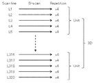
- the three-dimensional scan of this example is executed for 320 scan lines L1 to L320.
- One B scan consists of 320 A scans (see FIG. 4A).
- the A scan is a scan for one A line. That is, the A scan is a scan with respect to the A line along the incident direction (z direction, depth direction) of the measurement light LS.
- the B scan includes 320 A line scans arranged along the scan line Li on the xy plane orthogonal to the z direction.
- the B scan for the scan lines L1 to L320 is executed four times according to the arrangement order.
- Four B scans for each scan line Li are called repetition scans.
- the scan lines L1 to L320 are classified into groups of five according to the arrangement order.
- a set of 64 obtained by this classification is called a unit, and a scan for each unit is called a unit scan.
- the unit scan consists of four B scans for each of the five scan lines (that is, a total of 20 B scans).
- the abnormality detection process in this example is executed for each unit. If no abnormality is detected during the three-dimensional scan, 320 ⁇ 4 ⁇ 5 ⁇ 64 A scans are executed in the temporal order shown in FIG. 4A, and 4 ⁇ 5 ⁇ 64 B scan images are acquired. If an abnormality is detected, the unit is scanned again when the abnormality occurs, as will be described later.
- (1) to (3) are detected based on the OCT data, and (4) and (5) are detected based on the front image (fundus image).
- This embodiment has the following advantages by combining OCT and fundus imaging.
- the displacement amount of the eye to be examined cannot be obtained only by OCT, but in this embodiment, the scan position can be corrected (tracked) by obtaining the displacement amount by analyzing the front image.
- the OCT data analysis unit 231 detects the occurrence of abnormality by analyzing a series of data (interference signals) collected by one unit scan.
- the OCT data analysis unit 231 analyzes each A scan data (interference signal) included in each B scan data, and obtains a feature value representing the characteristic of the signal waveform. This feature value is, for example, the number of predetermined feature points in the signal waveform.
- This feature point is, for example, a turning point in the signal waveform (a point where an extreme value is taken, for example, a peak point protruding upward), or a point where the amplitude is zero (zero cross point).
- the OCT data analysis unit 231 identifies feature points in the A scan data and counts the number of the feature points. The above processing is executed for each of 320 pieces of A scan data included in the B scan data. Thereby, 320 feature values related to the B scan are obtained. A set of these 320 feature values is referred to as B-scan characteristic information. Such processing is executed for each of the 20 B scan data obtained by the unit scan. Thereby, 20 pieces of characteristic information regarding the unit scan are obtained. Further, the OCT data analysis unit 231 calculates an error between the two pieces of characteristic information, and detects the presence / absence of an abnormality based on the error. The error calculated here is, for example, a correlation coefficient or a mean square error.
- the OCT data analysis unit 231 calculates correlation coefficients of a plurality of pairs including different combinations of four characteristic information based on the repetition scan of this scan line. calculate.
- the plurality of pairs considered here are, for example, a pair of first characteristic information and second characteristic information, a pair of second characteristic information and third characteristic information, and third characteristic information and fourth characteristic information. It is a pair.
- the OCT data analysis unit 231 determines whether the calculated correlation coefficient is less than a predetermined threshold. If the correlation coefficient is less than the threshold value, it is determined that blinking has occurred during the repetition scan of this scan line.
- the interference signal acquired during blinking is only a noise component, and the correlation coefficient is almost zero.
- the above blink detection is a process using such a phenomenon.
- the correlation coefficient can be applied instead of the mean square error. Further, unlike the following (3), which requires 20 B scan data obtained by one unit scan, since this detection process (2) uses only a part of it, it is possible to detect fixation disparity at an early stage. There is. It is also possible to configure to execute only one of the detection processes (2) and (3).
- the OCT data analysis unit 231 has a plurality of pairs of different combinations of four characteristic information based on the repetition scan of this scan line.
- Each of the mean square errors is calculated, and the maximum value and the minimum value among the plurality of calculated mean square errors are specified.
- the plurality of pairs considered here are, for example, all combinations that select two from four pieces of characteristic information.
- the OCT data analysis unit 231 specifies the maximum value and the minimum value from the five maximum values and the five minimum values specified for the five scan lines that are the target of this unit scan.
- the maximum value and the minimum value specified here are the maximum value of the five maximum values and the minimum value of the five minimum values, respectively.
- the OCT data analysis unit 231 calculates the difference between the maximum value and the minimum value corresponding to this unit scan, and determines whether this difference exceeds a predetermined threshold value. When the difference exceeds the threshold value, it is determined that the eye E has been displaced (fixation shift has occurred) during this unit scan.
- the maximum value of the mean square error is obtained in consideration of all combinations (six) pairs of the four pieces of characteristic information.
- the present invention is not limited to this.
- any of the four B scans included in the repetition scan can be regarded as a scan for redundancy, and the maximum value can be obtained by excluding the B scan that gives an outlier. Since the repetition scan is performed in an extremely short time, it is considered that the factor that deteriorates the value of the mean square error is not fixation disparity but noise. According to this modification, it is possible to prevent erroneous detection of abnormality due to noise mixing.
- Imaging Data Analysis Unit 232 An example of processing executed by the imaging data analysis unit 232 will be described. As described above, the imaging data analysis unit 232 detects an abnormality by analyzing two or more fundus images including one or more fundus images acquired by the fundus camera unit 2 corresponding to the unit scan.
- the two or more fundus images to be analyzed include at least one fundus image acquired from the start to the end of this unit scan.
- an infrared fundus observation image is acquired in parallel with the above three-dimensional scan.
- the infrared fundus observation image is a moving image having a predetermined frame rate.
- the frame rate is set so that at least one frame is obtained during each unit scan.
- the frame rate of the infrared fundus observation image and the OCT scan conditions are at least for each unit scan. It is set so that one frame can be obtained.
- the imaging data analysis unit 232 analyzes two front images (frames of infrared fundus observation images) acquired at different timings, thereby determining the displacement amount (displacement direction) of the fundus oculi Ef depicted in these front images. Calculated).
- pattern matching such as a normalized correlation method or a phase only correlation method (POC) is used as in the conventional case.
- One of the two frames to be compared is, for example, a reference image (baseline image) acquired at the start of imaging (for example, at the start of OCT scan).
- the imaging data analysis unit 232 calculates the amount of displacement between the newly acquired front image (the frame acquired during a certain unit scan) and this reference image.
- the amount of displacement of the fundus oculi Ef can be obtained, for example, when the range of the fundus oculi Ef depicted in the two front images are completely different or out of focus. There is a case that cannot be done.
- the following processing can be executed.
- the imaging data analysis unit 232 obtains a normalized correlation value between the newly acquired front image and the reference image. If the normalized correlation value is less than a predetermined threshold, it is determined that an abnormality has occurred.
- a phase image representing a temporal change in phase between a plurality of B scan images obtained by repetition scanning can be created, and the correlation between such phase images can be used.
- a fundus image (such as the above-described captured image) obtained by flashing visible light or a fluorescent image.
- Threshold value used for determination of correlation value is set by an arbitrary method.
- a threshold value can be set in consideration of a low correlation value in an eye to be examined in which opacity occurs due to cataracts or the like. Further, when an abnormality is detected a predetermined number of times in this detection process (4) (when an error is determined), the threshold value can be decreased continuously or stepwise.
- the imaging data analysis unit 232 can calculate the amount of displacement between the two front images (the amount of displacement of the eye E). This process is executed, for example, when the occurrence of displacement is detected by the OCT data analysis unit 231. As a result, while detecting the occurrence of displacement using the OCT data, the amount of detected displacement can be obtained from the infrared fundus observation image or the like.
- the main control unit 211 can feed back the calculated displacement amount to the OCT scan.
- the storage unit 212 stores control information of the optical scanner 42 when the reference image is acquired and control information of the optical scanner 42 in each unit scan.
- the control information includes, for example, a coordinate group corresponding to the B scan.
- the main control unit 211 can correct the control information with the amount of displacement calculated by the imaging data analysis unit 232, and use the corrected control information to re-execute the unit scan in which the displacement is detected. Further, it is possible to obtain a displacement amount between the latest front image and the reference image and reflect this in the control information to execute the unit scan.
- an abnormality is detected by obtaining a displacement amount between the front image and the reference image corresponding to the unit scan and determining whether a difference between the displacement amount and the control information (coordinate group) is equal to or greater than a predetermined threshold.
- the threshold value at this time is set to 0.5 pixels, 0.7 pixels, or 1.0 pixels, for example.
- Preparation for shooting First, preparation for shooting is performed.
- the examiner activates the ophthalmologic imaging apparatus 1 and operates a key (graphical user interface icon or the like) for executing the above three-dimensional scan
- the main control unit 211 observes the fundus oculi Ef with the live OCT image. For this purpose is displayed on the display unit 241.
- the examiner moves the apparatus main body (fundus camera unit 2 or the like) in a direction away from the chin rest or the like using the operation unit 242 (for example, a joystick). Thereby, the anterior segment can be observed.
- the main control unit 211 turns on the observation light source 11 and causes the display unit 241 to display an observation image (anterior eye portion observation image) based on the output from the image sensor 35.
- the examiner (or the ophthalmologic photographing apparatus 1) adjusts the position of the apparatus main body so that the pupil is drawn at the center of the frame of the observation image.
- the examiner (or the ophthalmologic photographing apparatus 1) moves the apparatus main body closer to the eye E to be examined. Thereby, the observation target is switched from the anterior segment to the fundus oculi Ef, and an observation image of the fundus oculi Ef is displayed on the display unit 241.
- the main controller 211 controls the alignment optical system 50 to start projecting the alignment index (two alignment bright spots). Two alignment bright spot images are drawn on the observation image.
- the examiner or the ophthalmologic photographing apparatus 1) adjusts the position of the apparatus main body so that two alignment bright spot images are drawn in a target (such as a parenthesis mark) presented at the center of the frame.
- the main controller 211 controls the focus optical system 60 to start projecting the split index.
- adjustment of the optical path length for example, adjustment of the position of at least one of the optical path length changing unit 41 and the corner cube 114
- adjustment of the polarization state for example, control of at least one of the polarization controllers 103 and 118
- Adjustment of the amount of light for example, control of the attenuator 120
- adjustment of the focus for example, adjustment of the position of the OCT focusing lens 43
- the like are performed.
- the examiner (or the ophthalmologic photographing apparatus 1) confirms that problems such as flare mixing have not occurred in the observed image.
- the examiner uses the operation unit 242 to perform an operation for starting imaging.
- the main control unit 211 can overlay an image representing the current scan position by OCT on the observation image.
- the main control unit 211 registers the frame (front image) of the observation image obtained at this stage as a reference image.
- the imaging data analysis unit 232 starts processing for detecting a displacement between the reference image and a frame acquired thereafter. When the displacement exceeds the threshold due to the effect of blinking or fixation disparity or when the displacement cannot be detected, the main control unit 211 registers the newly acquired frame as a new reference image.
- the imaging data analysis unit 232 sequentially calculates the displacement between the frame acquired thereafter and the reference image.
- the main control unit 211 corrects the orientation of the optical scanner 42 so as to cancel the sequentially calculated displacement. This process may be executed in the same manner as in conventional tracking. The correction of the orientation of the optical scanner 42 is not performed while one repetition scan is being performed, but is performed after the completion.
- the method and timing for registering the reference image are not limited to this.
- the reference image can be registered by any method at any timing of the subsequent processing.
- the main control unit 211 determines a scan position (imaging position) by OCT. At the stage immediately after the start of imaging, a range to be subjected to three-dimensional scanning is set. Reference is now made to FIG. Reference symbol F indicates a frame of the observation image, and reference symbol R indicates a scan area of the three-dimensional scan.
- the scan area R is divided into 64 unit scan areas U1 to U64.
- the unit scan areas U1 to U64 correspond to the unit scans “# 1 Unit scan” to “# 64 Unit scan” shown in FIG. 4A, respectively. This scan area R is set immediately after the start of photographing.
- the main control unit 211 performs an OCT scan based on the imaging position determined in step S12. Immediately after the start of imaging, the three-dimensional scan for the scan area R is started from the scan for the first unit scan area U1 (“# 1 Unit scan” shown in FIG. 4A). In parallel with OCT, infrared moving image photographing of the fundus oculi Ef is executed at a predetermined frame rate.
- the main control unit 211 sends the data collected by the OCT scan for one unit scan area in step S13 and the frame of the observation image acquired in parallel with this unit scan to the data processing unit 230.
- the data processing unit 230 collects the OCT data for 20 B scans collected in the first unit scan (“# 1 Unit scan”) for the first unit scan area U1 and the first unit. An observation image frame acquired in parallel with the scan is acquired. Note that the OCT scan and infrared moving image shooting started in step S13 are executed in parallel with the abnormality detection processing in steps S21 to S25.
- the OCT data analysis unit 231 executes processing for detecting occurrence of an abnormality such as displacement or blinking of the eye E.
- the OCT data analysis unit 231 executes any of the detection processes (1) to (3) described above.
- the imaging data analysis unit 232 detects the occurrence of abnormality by executing, for example, the detection process (4).
- step S23 Has the occurrence of abnormality been detected If no abnormality is detected in step S22 (S23: No), that is, if it is determined that no abnormality has occurred during the unit scan, the process proceeds to step S25. On the other hand, when an abnormality that has occurred during the unit scan is detected (S23: Yes), the process proceeds to step S24.
- step S24 The amount of abnormality is detected
- the imaging data analysis unit 232 executes, for example, the detection process (5), thereby the amount of displacement of the eye E (displacement direction and displacement amount). Ask for. Then, the process proceeds to step S25.
- the abnormality detection process in steps S22 to S24 is executed as follows, for example.
- the detection process (1) is executed.
- the OCT data analysis unit 231 obtains the above-described characteristic information based on the OCT data obtained by the first four B scans of the unit scan, and calculates their correlation coefficients. If this correlation coefficient is less than the threshold value, it is determined that an abnormality has occurred, and other processing for detecting the occurrence of the abnormality is skipped, and the process proceeds to step S24.
- the process proceeds to the detection process (2). Specifically, the OCT data analysis unit 231 calculates the mean square error of each of the six pairs including all combinations of the four characteristic information based on the repetition scan, and determines whether the mean square error exceeds a threshold value. To do. If the mean square error exceeds the threshold value, it is determined that an abnormality has occurred, and other processing for detecting the occurrence of the abnormality is skipped, and the process proceeds to step S24. At this time, the maximum value and the minimum value of the mean square error are held.
- the detection processes (1) and (2) are executed for the four B scan data corresponding to the other scan lines included in the unit scan.
- the process proceeds to the detection process (3).
- the OCT data analysis unit 231 specifies the maximum value and the minimum value from the five maximum values and the five minimum values specified for the five scan lines that are the target of the unit scan, and these Calculate the difference. If this difference exceeds the threshold, it is determined that an abnormality has occurred, and other processing for detecting the occurrence of the abnormality is skipped and the process proceeds to step S24.
- the last B scan of the unit scan (20th B scan) Can be adopted as a reference image.
- the process proceeds to the detection process (4).
- the imaging data analysis unit 232 applies a normalized correlation method or a phase-only correlation method to each of the frames acquired during the unit scan and the reference image (or the phase image). The occurrence of an abnormality is detected by executing the correlation calculation of the above. If no abnormality is detected in any of the detection processes (1) to (4) (S23: No), the process proceeds to step S25.
- a difference between a plurality of displacements is calculated; whether or not the difference is deviated by at least one of a threshold value (for example, 0.5 pixel) in at least one of the x direction and the y direction (considering a correction amount of the scan position by tracking) Yes: If it is determined that the difference is greater than or equal to the threshold, it is determined that an abnormality has occurred.
- a threshold value for example, 0.5 pixel
- step S24 for example, the detection process (5) is executed. Specifically, the imaging data analysis unit 232 calculates the amount of displacement between the frame of the observation image and the reference image.
- the abnormality detection result acquired by the data processing unit 230 is stored in the storage unit 212.
- occurrence of abnormality is not detected in step S22 (S23: No), information indicating that is stored as a detection result.
- step S22 when the occurrence of an abnormality is detected in step S22 (S23: No) and the amount of this abnormality is detected (S24), for example, information indicating that an abnormality has been detected, the type of abnormality detected , Information indicating the amount of detected abnormality, and the like are stored as detection results.
- the main control unit 211 confirms (refers to) the detection result stored in step S25 and recognizes the presence / absence of an abnormality and the amount thereof.
- step S15: No abnormality If no abnormality is detected (S15: Yes), the process proceeds to step S16. On the other hand, when an abnormality is detected (S15: No), the process returns to step S12. At this time, the photographing position is determined so as to return the scan position to the first position of the unit scan where the abnormality is detected (S12). In addition, the photographing position can be corrected so as to cancel the detected displacement.
- the process returns to step S12.
- the unit scan area next to the unit scan area of the unit scan (or the unit scan area next to the unit scan area where the unit scan is currently being executed) is set as the imaging position (S12).
- the photographing position can be corrected so as to cancel the detected displacement.
- step S17 If the unit scan is an OCT scan of the last unit scan area U64 (S16: Yes), the process proceeds to step S17.
- an abnormality is detected in the last unit scan (“# 64 Unit scan” shown in FIG. 4A) (S17: No) (S17: No) (S17: No) (S17: No) (S17: No) (S17: No) (S17: No) (S17: No) (S17: No)
- the process returns to step S12. At this time, the photographing position is determined so as to return the scan position to the first position of the last unit scan (S12). In addition, the photographing position can be corrected so as to cancel the detected displacement.
- the ophthalmic imaging apparatus includes a data collection unit, an imaging unit, a control unit, and an abnormality detection unit.
- the data collection unit collects data by scanning the eye to be examined using optical coherence tomography (OCT).
- OCT optical coherence tomography
- the data collection unit includes, for example, the OCT unit 100 and elements in the fundus camera unit 2 that form a measurement optical path.
- the imaging unit captures the eye to be examined and acquires a front image.
- the photographing unit includes, for example, an illumination optical system 10 and a photographing optical system 30.
- the control unit controls the data collection unit to perform a series of scans along a preset route group.
- the control unit includes a main control unit 211, for example.
- a unit scan along a path group consisting of five scan lines is executed as this series of scans.
- the abnormality detection unit detects an abnormality based on a series of data collected by a series of scans and two or more front images including one or more front images acquired by the imaging unit corresponding to the series of scans. To do.
- One of the two or more front images may be a reference image.
- the detection of abnormality may include at least one of detection of occurrence of abnormality and detection of the amount of abnormality.
- the embodiment configured as described above it is possible to detect the movement and blink of the eye to be examined using an OCT scan whose repetition rate is sufficiently higher than the frame rate of the video camera. Further, it is possible to detect the movement of the eye to be examined and the occurrence of blinking, and the amount of movement of the eye to be examined from the front image. Therefore, it is possible to obtain an OCT image with high accuracy even when the eye to be examined moves or blinks.
- the abnormality detection unit includes a first abnormality detection unit that detects occurrence of an abnormality based on a series of data collected by a series of scans using OCT, and two or more front images obtained by the imaging unit. And a second abnormality detection unit that detects the amount of abnormality based on the above.
- the first abnormality detection unit includes an OCT data analysis unit 231
- the second abnormality detection unit includes an imaging data analysis unit 232.
- the second abnormality detection unit may be configured to detect the amount of the abnormality.
- a series of scans using the OCT may include scans (repetition scans) that are sequentially executed a predetermined number of times with respect to the path group.
- the series of data may include a predetermined number of data sets (a plurality of B scan data obtained by repetition scanning of each scan line) corresponding to each path included in the path group.
- the first abnormality detection unit may be configured to obtain characteristic information of each of a predetermined number of data sets and detect occurrence of an abnormality based on the characteristic information.
- the first anomaly detection unit calculates and calculates each error (mean square error, etc.) of a plurality of pairs made up of different combinations of a predetermined number of characteristic information for each path of the path group.
- a maximum value and a minimum value of the plurality of errors may be specified.
- the first abnormality detection unit detects an abnormality during the series of scans when a difference between the maximum value and the minimum value among the plurality of maximum values and the plurality of minimum values specified for the path group exceeds a threshold value. Can be determined to have occurred.
- An example of this process is the detection process (3) in the above embodiment.
- the first abnormality detection unit is configured to calculate an error (such as a mean square error) of each of a plurality of pairs including different combinations of a predetermined number of characteristic information for each of the routes in the route group. Good. Furthermore, when the calculated error exceeds the threshold, the first abnormality detection unit can determine that an abnormality has occurred during the scan for the path.
- an error such as a mean square error
- the first abnormality detection unit can determine that an abnormality has occurred during the scan for the path.
- An example of this process is the detection process (2) in the above embodiment.
- the first abnormality detection unit calculates a correlation coefficient of a plurality of pairs including different combinations of a predetermined number of characteristic information for each path of the path group, and the calculated correlation coefficient is less than a threshold value. If so, it may be configured to determine that an abnormality has occurred during the scan for the path.
- An example of this process is the detection process (1) in the above embodiment.
- the first abnormality detection unit is configured to store, for each of the predetermined number of data sets (a plurality of B scan data obtained by repetition scanning of each scan line), a plurality of A scan data included in the data set. Each of them may be analyzed to obtain a feature value representing the feature of the signal waveform, and the characteristic information may be obtained based on the plurality of obtained feature values.
- This feature value may be the number of predetermined feature points in this signal waveform. This feature point may be an extreme point or a zero cross point.
- the second abnormality detection unit may be configured to detect a displacement between two or more front images as an amount of abnormality. Furthermore, the second abnormality detection unit can calculate the displacement between two or more front images using the phase only correlation method.
- the abnormality detection unit may include a third abnormality detection unit that detects the occurrence of abnormality based on the front image.
- the third abnormality detection unit calculates a correlation coefficient between two or more front images, and when this correlation coefficient is less than a threshold, an abnormality (displacement of the eye to be examined, focus shift) is detected during scanning with respect to the path. Etc.).
- An example of this process is the detection process (4) in the above embodiment.
- the imaging data analysis unit 232 is an example of a third abnormality detection unit.
- the control unit when an abnormality is detected by the abnormality detection unit (that is, when an abnormality occurs or when the amount of abnormality is large), the control unit performs a series of scans performed when the abnormality occurs.
- the data collection unit can be controlled to perform again. As a result, the area that was being scanned when the abnormality occurred can be scanned again to reacquire data.
- control unit can control the data collection unit to sequentially perform a series of scans on a plurality of preset route groups.
- the abnormality detection unit can perform the above-described abnormality detection for each route group.
- abnormality detection is performed for each unit scan area while performing unit scans sequentially on 64 unit scan areas. This makes it possible to acquire a highly accurate three-dimensional OCT image (volume data or the like) even when the eye to be examined moves or blinks.
Landscapes
- Health & Medical Sciences (AREA)
- Life Sciences & Earth Sciences (AREA)
- Engineering & Computer Science (AREA)
- Medical Informatics (AREA)
- General Health & Medical Sciences (AREA)
- Physics & Mathematics (AREA)
- Animal Behavior & Ethology (AREA)
- Veterinary Medicine (AREA)
- Heart & Thoracic Surgery (AREA)
- Ophthalmology & Optometry (AREA)
- Molecular Biology (AREA)
- Surgery (AREA)
- Biophysics (AREA)
- Biomedical Technology (AREA)
- Public Health (AREA)
- Nuclear Medicine, Radiotherapy & Molecular Imaging (AREA)
- Radiology & Medical Imaging (AREA)
- Signal Processing (AREA)
- Human Computer Interaction (AREA)
- Quality & Reliability (AREA)
- Computer Vision & Pattern Recognition (AREA)
- General Physics & Mathematics (AREA)
- Theoretical Computer Science (AREA)
- Eye Examination Apparatus (AREA)
Abstract
L'appareil d'imagerie ophtalmologique selon un mode de réalisation de la présente invention comprend une unité de collecte de données, une unité d'imagerie, une unité de commande, et une unité de détection d'anomalie. L'unité de collecte de données collecte des données par balayage d'un œil du sujet en utilisant la tomographie par cohérence optique. L'unité d'imagerie capture une image de l'œil du sujet et acquiert une image de face. L'unité de commande commande l'unité de collecte de données de sorte qu'une série de balayages est effectuée le long d'un groupe de trajets prédéfinis. L'unité de détection d'anomalie détecte une anomalie sur la base d'une série de données collectées par une série de balayages et d'au moins deux images de face comprenant au moins une image de face acquise par l'unité d'imagerie en fonction de la série de balayages.
Priority Applications (3)
| Application Number | Priority Date | Filing Date | Title |
|---|---|---|---|
| EP17759400.9A EP3424404A4 (fr) | 2016-02-29 | 2017-01-06 | Appareil d'imagerie ophtalmologique |
| EP20210935.1A EP3821791A1 (fr) | 2016-02-29 | 2017-01-06 | Appareil d'imagerie ophtalmologique |
| US16/080,019 US10786153B2 (en) | 2016-02-29 | 2017-01-06 | Ophthalmologic imaging apparatus |
Applications Claiming Priority (2)
| Application Number | Priority Date | Filing Date | Title |
|---|---|---|---|
| JP2016-037152 | 2016-02-29 | ||
| JP2016037152A JP2017153543A (ja) | 2016-02-29 | 2016-02-29 | 眼科撮影装置 |
Publications (1)
| Publication Number | Publication Date |
|---|---|
| WO2017149928A1 true WO2017149928A1 (fr) | 2017-09-08 |
Family
ID=59742820
Family Applications (1)
| Application Number | Title | Priority Date | Filing Date |
|---|---|---|---|
| PCT/JP2017/000310 WO2017149928A1 (fr) | 2016-02-29 | 2017-01-06 | Appareil d'imagerie ophtalmologique |
Country Status (4)
| Country | Link |
|---|---|
| US (1) | US10786153B2 (fr) |
| EP (2) | EP3424404A4 (fr) |
| JP (1) | JP2017153543A (fr) |
| WO (1) | WO2017149928A1 (fr) |
Families Citing this family (10)
| Publication number | Priority date | Publication date | Assignee | Title |
|---|---|---|---|---|
| JP7123626B2 (ja) * | 2018-05-24 | 2022-08-23 | キヤノン株式会社 | 眼底撮影装置およびその制御方法 |
| JP2020039667A (ja) | 2018-09-12 | 2020-03-19 | 株式会社トプコン | 眼科撮影装置、その制御方法、プログラム、及び記録媒体 |
| JP7215862B2 (ja) | 2018-09-26 | 2023-01-31 | 株式会社トプコン | 眼科撮影装置、その制御方法、プログラム、及び記録媒体 |
| JP7216545B2 (ja) * | 2018-12-26 | 2023-02-01 | 株式会社トプコン | 眼科装置、眼科装置の制御方法、及びプログラム |
| CN110123267B (zh) * | 2019-03-22 | 2022-02-08 | 重庆康华瑞明科技股份有限公司 | 基于眼科裂隙灯的附加泛光投影装置及图像分析系统 |
| JP7335107B2 (ja) * | 2019-07-23 | 2023-08-29 | 株式会社トプコン | 眼科情報処理装置、眼科装置、眼科情報処理方法、及びプログラム |
| US11568540B2 (en) * | 2019-10-07 | 2023-01-31 | Optos Plc | System, method, and computer-readable medium for rejecting full and partial blinks for retinal tracking |
| ES2929783T3 (es) * | 2020-07-17 | 2022-12-01 | Optos Plc | Sistema de obtención de imágenes para tomografía de coherencia óptica binocular |
| JP7560300B2 (ja) | 2020-09-15 | 2024-10-02 | 株式会社トプコン | スリットランプ顕微鏡システム |
| JP7560303B2 (ja) | 2020-09-18 | 2024-10-02 | 株式会社トプコン | スリットランプ顕微鏡システム |
Citations (6)
| Publication number | Priority date | Publication date | Assignee | Title |
|---|---|---|---|---|
| JP2010110556A (ja) * | 2008-11-10 | 2010-05-20 | Canon Inc | 画像処理装置、画象処理方法、プログラム、及びプログラム記憶媒体 |
| JP2010201102A (ja) * | 2009-03-06 | 2010-09-16 | Canon Inc | 光断層画像撮像装置 |
| JP2010264225A (ja) * | 2009-04-15 | 2010-11-25 | Topcon Corp | 眼底観察装置 |
| JP2011215134A (ja) * | 2010-03-16 | 2011-10-27 | Nidek Co Ltd | 光断層像撮影装置 |
| JP2011254959A (ja) * | 2010-06-08 | 2011-12-22 | Canon Inc | 画像処理装置、画像処理方法、及びプログラム |
| JP2013180125A (ja) * | 2012-03-02 | 2013-09-12 | Nidek Co Ltd | 眼科撮影装置 |
Family Cites Families (13)
| Publication number | Priority date | Publication date | Assignee | Title |
|---|---|---|---|---|
| EP1602322A1 (fr) * | 2004-06-02 | 2005-12-07 | SensoMotoric Instruments GmbH | Méthode et appareil pour réduction de temps d'inactivité d'un appareil de poursuite oculaire |
| JP5683946B2 (ja) | 2007-04-10 | 2015-03-11 | ユニヴァーシティー オブ サザン カリフォルニア | ドップラー光コヒーレンス・トモグラフィを用いた血流測定のための方法とシステム |
| JP5706506B2 (ja) | 2009-04-15 | 2015-04-22 | 株式会社トプコン | 眼科装置 |
| JP5025715B2 (ja) | 2009-12-08 | 2012-09-12 | キヤノン株式会社 | 断層画像撮影装置、画像処理装置、画像処理システム、画像処理装置の制御方法及びプログラム |
| CN103502770B (zh) | 2011-04-29 | 2017-02-08 | 光视有限公司 | 使用光学相干断层扫描进行实时跟踪的改进成像 |
| WO2013004801A1 (fr) * | 2011-07-07 | 2013-01-10 | Carl Zeiss Meditec Ag | Procédés améliorés d'acquisition de données pour réduire les artefacts de mouvement et applications en angiographie par oct |
| US20130229622A1 (en) | 2012-03-02 | 2013-09-05 | Nidek Co., Ltd. | Ophthalmologic photographing apparatus and ophthalmologic photographing method |
| US9357916B2 (en) | 2012-05-10 | 2016-06-07 | Carl Zeiss Meditec, Inc. | Analysis and visualization of OCT angiography data |
| JP6112846B2 (ja) * | 2012-12-11 | 2017-04-12 | 株式会社トプコン | 眼科装置 |
| JP6160808B2 (ja) * | 2013-01-23 | 2017-07-12 | 株式会社ニデック | 眼科撮影装置及び眼科撮影プログラム |
| US9295387B2 (en) | 2013-04-03 | 2016-03-29 | Kabushiki Kaisha Topcon | Ophthalmologic apparatus |
| US9295386B2 (en) | 2013-04-03 | 2016-03-29 | Kabushiki Kaisha Topcon | Ophthalmologic apparatus |
| US9370301B2 (en) | 2013-04-03 | 2016-06-21 | Kabushiki Kaisha Topcon | Ophthalmologic apparatus |
-
2016
- 2016-02-29 JP JP2016037152A patent/JP2017153543A/ja active Pending
-
2017
- 2017-01-06 EP EP17759400.9A patent/EP3424404A4/fr not_active Ceased
- 2017-01-06 EP EP20210935.1A patent/EP3821791A1/fr active Pending
- 2017-01-06 WO PCT/JP2017/000310 patent/WO2017149928A1/fr active Application Filing
- 2017-01-06 US US16/080,019 patent/US10786153B2/en active Active
Patent Citations (6)
| Publication number | Priority date | Publication date | Assignee | Title |
|---|---|---|---|---|
| JP2010110556A (ja) * | 2008-11-10 | 2010-05-20 | Canon Inc | 画像処理装置、画象処理方法、プログラム、及びプログラム記憶媒体 |
| JP2010201102A (ja) * | 2009-03-06 | 2010-09-16 | Canon Inc | 光断層画像撮像装置 |
| JP2010264225A (ja) * | 2009-04-15 | 2010-11-25 | Topcon Corp | 眼底観察装置 |
| JP2011215134A (ja) * | 2010-03-16 | 2011-10-27 | Nidek Co Ltd | 光断層像撮影装置 |
| JP2011254959A (ja) * | 2010-06-08 | 2011-12-22 | Canon Inc | 画像処理装置、画像処理方法、及びプログラム |
| JP2013180125A (ja) * | 2012-03-02 | 2013-09-12 | Nidek Co Ltd | 眼科撮影装置 |
Non-Patent Citations (1)
| Title |
|---|
| See also references of EP3424404A4 * |
Also Published As
| Publication number | Publication date |
|---|---|
| EP3821791A1 (fr) | 2021-05-19 |
| US20190059720A1 (en) | 2019-02-28 |
| US10786153B2 (en) | 2020-09-29 |
| EP3424404A1 (fr) | 2019-01-09 |
| JP2017153543A (ja) | 2017-09-07 |
| EP3424404A4 (fr) | 2019-11-27 |
Similar Documents
| Publication | Publication Date | Title |
|---|---|---|
| WO2017149928A1 (fr) | Appareil d'imagerie ophtalmologique | |
| JP6354979B2 (ja) | 眼底撮影装置 | |
| JP6899632B2 (ja) | 眼科撮影装置 | |
| JP6616704B2 (ja) | 眼科装置及び眼科検査システム | |
| JP6349878B2 (ja) | 眼科撮影装置、眼科撮影方法、及び眼科撮影プログラム | |
| JP2019041841A (ja) | 眼科装置、及びその制御方法 | |
| WO2018135175A1 (fr) | Dispositif ophtalmologique | |
| JP6585897B2 (ja) | 眼科撮影装置 | |
| JP2023009257A (ja) | 眼科情報処理装置、眼科撮影装置、眼科情報処理方法、及びプログラム | |
| JP2023080218A (ja) | 眼科装置 | |
| JP7096392B2 (ja) | 眼科装置 | |
| JP6421919B2 (ja) | 眼科撮影装置 | |
| JP2016049368A (ja) | 眼科撮影装置 | |
| JP2018038687A (ja) | 眼科装置 | |
| JP2017136217A (ja) | 眼科装置及び眼科検査システム | |
| JP7118197B2 (ja) | 眼科装置 | |
| JP2022171787A (ja) | 眼科装置 | |
| JP2019170710A (ja) | 眼科装置 | |
| JP2023101618A (ja) | 眼科撮影装置 | |
| JP2022031533A (ja) | 眼科撮影装置 | |
| JP7314345B2 (ja) | 眼科装置、及びその制御方法 | |
| JP2021072978A (ja) | 眼科撮影装置 | |
| JP2021072979A (ja) | 眼科撮影装置 | |
| JP7286853B2 (ja) | 眼科装置、及びその制御方法 | |
| JP7202808B2 (ja) | 眼科装置、及びその制御方法 |
Legal Events
| Date | Code | Title | Description |
|---|---|---|---|
| NENP | Non-entry into the national phase |
Ref country code: DE |
|
| WWE | Wipo information: entry into national phase |
Ref document number: 2017759400 Country of ref document: EP |
|
| ENP | Entry into the national phase |
Ref document number: 2017759400 Country of ref document: EP Effective date: 20181001 |
|
| 121 | Ep: the epo has been informed by wipo that ep was designated in this application |
Ref document number: 17759400 Country of ref document: EP Kind code of ref document: A1 |