WO2017149928A1 - Ophthalmologic imaging apparatus - Google Patents
Ophthalmologic imaging apparatus Download PDFInfo
- Publication number
- WO2017149928A1 WO2017149928A1 PCT/JP2017/000310 JP2017000310W WO2017149928A1 WO 2017149928 A1 WO2017149928 A1 WO 2017149928A1 JP 2017000310 W JP2017000310 W JP 2017000310W WO 2017149928 A1 WO2017149928 A1 WO 2017149928A1
- Authority
- WO
- WIPO (PCT)
- Prior art keywords
- abnormality
- unit
- scan
- detection unit
- series
- Prior art date
Links
Images


Classifications
-
- A—HUMAN NECESSITIES
- A61—MEDICAL OR VETERINARY SCIENCE; HYGIENE
- A61B—DIAGNOSIS; SURGERY; IDENTIFICATION
- A61B3/00—Apparatus for testing the eyes; Instruments for examining the eyes
- A61B3/10—Objective types, i.e. instruments for examining the eyes independent of the patients' perceptions or reactions
- A61B3/14—Arrangements specially adapted for eye photography
-
- A—HUMAN NECESSITIES
- A61—MEDICAL OR VETERINARY SCIENCE; HYGIENE
- A61B—DIAGNOSIS; SURGERY; IDENTIFICATION
- A61B3/00—Apparatus for testing the eyes; Instruments for examining the eyes
- A61B3/0016—Operational features thereof
- A61B3/0025—Operational features thereof characterised by electronic signal processing, e.g. eye models
-
- A—HUMAN NECESSITIES
- A61—MEDICAL OR VETERINARY SCIENCE; HYGIENE
- A61B—DIAGNOSIS; SURGERY; IDENTIFICATION
- A61B3/00—Apparatus for testing the eyes; Instruments for examining the eyes
- A61B3/10—Objective types, i.e. instruments for examining the eyes independent of the patients' perceptions or reactions
- A61B3/102—Objective types, i.e. instruments for examining the eyes independent of the patients' perceptions or reactions for optical coherence tomography [OCT]
-
- A—HUMAN NECESSITIES
- A61—MEDICAL OR VETERINARY SCIENCE; HYGIENE
- A61B—DIAGNOSIS; SURGERY; IDENTIFICATION
- A61B3/00—Apparatus for testing the eyes; Instruments for examining the eyes
- A61B3/10—Objective types, i.e. instruments for examining the eyes independent of the patients' perceptions or reactions
- A61B3/113—Objective types, i.e. instruments for examining the eyes independent of the patients' perceptions or reactions for determining or recording eye movement
-
- G—PHYSICS
- G06—COMPUTING; CALCULATING OR COUNTING
- G06T—IMAGE DATA PROCESSING OR GENERATION, IN GENERAL
- G06T7/00—Image analysis
- G06T7/0002—Inspection of images, e.g. flaw detection
- G06T7/0012—Biomedical image inspection
-
- G—PHYSICS
- G06—COMPUTING; CALCULATING OR COUNTING
- G06T—IMAGE DATA PROCESSING OR GENERATION, IN GENERAL
- G06T2207/00—Indexing scheme for image analysis or image enhancement
- G06T2207/10—Image acquisition modality
- G06T2207/10072—Tomographic images
- G06T2207/10101—Optical tomography; Optical coherence tomography [OCT]
-
- G—PHYSICS
- G06—COMPUTING; CALCULATING OR COUNTING
- G06T—IMAGE DATA PROCESSING OR GENERATION, IN GENERAL
- G06T2207/00—Indexing scheme for image analysis or image enhancement
- G06T2207/30—Subject of image; Context of image processing
- G06T2207/30004—Biomedical image processing
- G06T2207/30041—Eye; Retina; Ophthalmic
Definitions
- the present invention relates to an ophthalmologic photographing apparatus that images an eye to be examined using optical coherence tomography (OCT).
- OCT optical coherence tomography
- Diagnostic imaging occupies an important position in the ophthalmology field.
- OCT has been used not only for acquiring B-mode images and three-dimensional images of the eye to be examined, but also for acquiring front images (en-face images) such as C-mode images and shadowgrams.
- part of the eye to be examined, and acquiring functional information are also performed.
- an image (angiogram) in which retinal blood vessels and choroidal blood vessels are emphasized can be constructed based on time-series data collected by OCT.
- blood flow information blood flow velocity, blood flow volume, etc.
- Such an imaging technique is disclosed in, for example, Patent Documents 1-3.
- a technique is also known in which a plurality of images are acquired by repeatedly scanning the same cross section, and these are averaged to create a low noise image (see, for example, Patent Document 4).
- Tracking is a technique for monitoring the movement of an eye to be examined during scanning with a video camera and controlling the optical scanner in real time according to the movement (see, for example, Patent Document 5).
- the rescan is a technique of monitoring the eye under examination with a video camera and rescanning the scanned position at the timing when the eye to be moved largely or the timing of blinking (see, for example, Patent Document 6). .
- the video from the video camera is analyzed to detect movement and blinking of the eye to be examined.
- the repetition rate of OCT scans for example, the repetition rate of B scans
- the frame rate of the video camera is about 20 to 50 FPS (frame interval about 20 to 50 ms).
- FPS frame interval about 20 to 50 ms
- An object of the present invention is to provide an ophthalmologic imaging apparatus capable of acquiring a highly accurate OCT image even when a subject's eye moves or blinks.
- the ophthalmic imaging apparatus includes a data collection unit, an imaging unit, a control unit, and an abnormality detection unit.
- the data collection unit collects data by scanning the eye to be examined using optical coherence tomography.
- the imaging unit captures the eye to be examined and acquires a front image.
- the control unit controls the data collection unit to perform a series of scans along a preset route group.
- the abnormality detection unit detects an abnormality based on a series of data collected by a series of scans and two or more front images including one or more front images acquired by the imaging unit corresponding to the series of scans. To do.
- the ophthalmologic photographing apparatus it is possible to acquire a highly accurate OCT image even when the eye to be examined moves or blinks.
- Schematic showing the example of a structure of the ophthalmologic imaging device which concerns on embodiment Schematic showing the example of a structure of the ophthalmologic imaging device which concerns on embodiment. Schematic showing the example of a structure of the ophthalmologic imaging device which concerns on embodiment. Schematic showing the example of a structure of the ophthalmologic imaging device which concerns on embodiment. Schematic showing the example of operation
- the embodiment is an ophthalmologic photographing apparatus having a function as an optical coherence tomography (OCT) and a function of acquiring a front image of an eye to be examined.
- OCT optical coherence tomography
- the latter function can be realized by, for example, a fundus camera, a scanning laser ophthalmoscope (SLO), a slit lamp microscope, an ophthalmic surgical microscope, an anterior ocular segment imaging camera, or the like.
- SLO scanning laser ophthalmoscope
- a slit lamp microscope an ophthalmic surgical microscope
- anterior ocular segment imaging camera or the like.
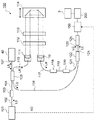
- the ophthalmologic photographing apparatus 1 includes a fundus camera unit 2, an OCT unit 100, and an arithmetic control unit 200.
- the fundus camera unit 2 is provided with an optical system and a mechanism for acquiring a front image of the eye to be examined.
- the OCT unit 100 is provided with an optical system and a mechanism for performing OCT.
- the arithmetic control unit 200 includes a processor that executes various arithmetic operations and controls. In addition to these, a member for supporting the subject's face (chin rest, forehead rest, etc.) and a lens unit (for example, an anterior ocular segment OCT attachment) for switching an OCT target site may be provided. Good.
- the “processor” is, for example, a CPU (Central Processing Unit), a GPU (Graphics Processing Unit), an ASIC (Application Specific Integrated Circuit), a programmable logic device (eg, SPLD (Simple ProGLD). It means a circuit such as Programmable Logic Device (FPGA) or Field Programmable Gate Array (FPGA).
- the processor implements the functions according to the embodiment by reading and executing a program stored in a storage circuit or a storage device.
- the fundus camera unit 2 is provided with an optical system for photographing the fundus oculi Ef of the eye E to be examined.
- the acquired image of the fundus oculi Ef (referred to as a fundus oculi image, a fundus oculi photo, or the like) is a front image such as an observation image or a captured image.
- the observation image is obtained by moving image shooting using near infrared light.
- the photographed image is a still image using flash light.
- the fundus camera unit 2 includes an illumination optical system 10 and a photographing optical system 30.
- the illumination optical system 10 irradiates the eye E with illumination light.
- the imaging optical system 30 detects the return light of the illumination light from the eye E.
- the measurement light from the OCT unit 100 is guided to the eye E through the optical path in the fundus camera unit 2, and the return light is guided to the OCT unit 100 through the same optical path.
- the light (observation illumination light) output from the observation light source 11 of the illumination optical system 10 is reflected by the reflection mirror 12 having a curved reflecting surface, passes through the condensing lens 13 and passes through the visible cut filter 14. Near infrared light. Further, the observation illumination light is once converged in the vicinity of the photographing light source 15, reflected by the mirror 16, and passes through the relay lenses 17 and 18, the diaphragm 19 and the relay lens 20. The observation illumination light is reflected by the peripheral part of the perforated mirror 21 (area around the perforated part), passes through the dichroic mirror 46, and is refracted by the objective lens 22 to be examined eye E (fundus Ef or anterior eye). Part).
- the return light of the observation illumination light from the eye E is refracted by the objective lens 22, passes through the dichroic mirror 46, passes through the hole formed in the central region of the perforated mirror 21, and passes through the dichroic mirror 55.
- the light is reflected by the mirror 32 via the photographing focusing lens 31. Further, the return light passes through the half mirror 33A, is reflected by the dichroic mirror 33, and forms an image on the light receiving surface of the image sensor 35 by the condenser lens.
- the image sensor 35 detects return light at a predetermined frame rate. Note that the focus of the photographing optical system 30 is adjusted with respect to the fundus oculi Ef or the anterior eye segment.
- the light (imaging illumination light) output from the imaging light source 15 is irradiated onto the fundus oculi Ef through the same path as the observation illumination light.
- the return light of the imaging illumination light from the eye E is guided to the dichroic mirror 33 through the same path as the return light of the observation illumination light, passes through the dichroic mirror 33, is reflected by the mirror 36, and is reflected by the condenser lens 37.
- An image is formed on the light receiving surface of the image sensor 38.
- LCD39 displays a fixation target and a visual target for visual acuity measurement.
- a part of the light beam output from the LCD 39 is reflected by the half mirror 33 ⁇ / b> A, reflected by the mirror 32, passes through the hole of the perforated mirror 21 through the photographing focusing lens 31 and the dichroic mirror 55.
- the fixation light beam that has passed through the hole of the aperture mirror 21 passes through the dichroic mirror 46, is refracted by the objective lens 22, and is projected onto the fundus oculi Ef.
- the alignment optical system 50 generates an alignment index used for alignment of the optical system with respect to the eye E.
- the alignment light output from the LED 51 passes through the apertures 52 and 53 and the relay lens 54, is reflected by the dichroic mirror 55, and passes through the hole of the perforated mirror 21.
- the light that has passed through the hole of the perforated mirror 21 passes through the dichroic mirror 46 and is projected onto the eye E by the objective lens 22.
- the corneal reflection light of the alignment light is guided to the image sensor 35 through the same path as the return light of the observation illumination light.
- Manual alignment and auto-alignment can be executed based on the received light image (alignment index image).
- the focus optical system 60 generates a split index used for focus adjustment on the eye E.
- the focus optical system 60 is moved along the optical path (illumination optical path) of the illumination optical system 10 in conjunction with the movement of the imaging focusing lens 31 along the optical path (imaging optical path) of the imaging optical system 30.
- the reflection bar 67 can be inserted into and removed from the illumination optical path.
- the reflecting surface of the reflecting bar 67 is inclinedly arranged in the illumination optical path.
- the focus light output from the LED 61 passes through the relay lens 62, is separated into two light beams by the split indicator plate 63, passes through the two-hole aperture 64, is reflected by the mirror 65, and is reflected by the condenser lens 66 as a reflecting rod 67.
- the light is once imaged and reflected on the reflection surface. Further, the focus light passes through the relay lens 20, is reflected by the perforated mirror 21, passes through the dichroic mirror 46, is refracted by the objective lens 22, and is projected onto the fundus oculi Ef.
- the fundus reflected light of the focus light is guided to the image sensor 35 through the same path as the cornea reflected light of the alignment light. Manual alignment and auto alignment can be executed based on the received light image (split index image).
- the diopter correction lenses 70 and 71 can be selectively inserted into the photographing optical path between the perforated mirror 21 and the dichroic mirror 55.
- the diopter correction lens 70 is a plus lens (convex lens) for correcting the intensity hyperopia.
- the diopter correction lens 71 is a minus lens (concave lens) for correcting intensity myopia.
- the optical path length changing unit 41 is movable in the direction of the arrow shown in FIG. 1, and changes the optical path length for OCT. This change in optical path length is used for optical path length correction according to the axial length, adjustment of the interference state, and the like.
- the optical path length changing unit 41 includes a corner cube and a mechanism for moving the corner cube.
- the optical scanner 42 is disposed at a position optically conjugate with the pupil of the eye E to be examined.
- the optical scanner 42 deflects the measurement light LS passing through the optical path for OCT.
- the optical scanner 42 is, for example, a galvano scanner capable of two-dimensional scanning.
- the OCT focusing lens 43 is moved along the optical path of the measurement light LS in order to adjust the focus of the optical system for OCT.
- the movement of the photographing focusing lens 31, the movement of the focus optical system 60, and the movement of the OCT focusing lens 43 can be controlled in a coordinated manner.
- the OCT unit 100 is provided with an optical system for executing the swept source OCT.
- This optical system divides the light from the wavelength tunable light source (wavelength sweep type light source) into the measurement light and the reference light, and causes the return light of the measurement light from the eye E to interfere with the reference light via the reference light path.
- An interference optical system that generates interference light and detects the interference light.
- a detection result (detection signal) obtained by the interference optical system is a signal indicating the spectrum of the interference light, and is sent to the arithmetic control unit 200.
- the light source unit 101 includes, for example, a near-infrared wavelength tunable laser that changes the wavelength of emitted light at high speed.
- the light L0 output from the light source unit 101 is guided to the polarization controller 103 by the optical fiber 102 and its polarization state is adjusted. Further, the light L0 is guided to the fiber coupler 105 by the optical fiber 104 and is divided into the measurement light LS and the reference light LR.
- the reference light LR is guided to the collimator 111 by the optical fiber 110, converted into a parallel light beam, and guided to the corner cube 114 via the optical path length correction member 112 and the dispersion compensation member 113.
- the optical path length correction member 112 acts to match the optical path length of the reference light LR and the optical path length of the measurement light LS.
- the dispersion compensation member 113 acts to match the dispersion characteristics between the reference light LR and the measurement light LS.
- the corner cube 114 is movable in the incident direction of the reference light LR, and thereby the optical path length of the reference light LR is changed.
- the reference light LR that has passed through the corner cube 114 is converted from a parallel light beam into a converged light beam by the collimator 116 via the dispersion compensation member 113 and the optical path length correction member 112, and enters the optical fiber 117.
- the reference light LR incident on the optical fiber 117 is guided to the polarization controller 118 and its polarization state is adjusted.
- the reference light LR is guided to the attenuator 120 by the optical fiber 119 and the amount of light is adjusted, and is guided to the fiber coupler 122 by the optical fiber 121. It is burned.
- the measurement light LS generated by the fiber coupler 105 is guided by the optical fiber 127 and converted into a parallel light beam by the collimator lens unit 40, and the optical path length changing unit 41, the optical scanner 42, the OCT focusing lens 43, and the mirror 44. Then, the light passes through the relay lens 45, is reflected by the dichroic mirror 46, is refracted by the objective lens 22, and enters the eye E to be examined.
- the measurement light LS is scattered and reflected at various depth positions of the eye E.
- the return light of the measurement light LS from the eye E travels in the reverse direction on the same path as the forward path, is guided to the fiber coupler 105, and reaches the fiber coupler 122 via the optical fiber 128.
- the fiber coupler 122 combines (interferences) the measurement light LS incident through the optical fiber 128 and the reference light LR incident through the optical fiber 121 to generate interference light.
- the fiber coupler 122 generates a pair of interference light LC by branching the interference light at a predetermined branching ratio (for example, 1: 1).
- the pair of interference lights LC are guided to the detector 125 through optical fibers 123 and 124, respectively.
- the detector 125 is, for example, a balanced photodiode.
- the balanced photodiode has a pair of photodetectors that respectively detect the pair of interference lights LC, and outputs a difference between detection results obtained by these.
- the detector 125 sends this output (detection signal) to a DAQ (Data Acquisition System) 130.
- DAQ Data Acquisition System
- the clock KC is supplied from the light source unit 101 to the DAQ 130.
- the clock KC is generated in synchronization with the output timing of each wavelength that is swept within a predetermined wavelength range by the wavelength variable light source in the light source unit 101.
- the light source unit 101 optically delays one of the two branched lights obtained by branching the light L0 of each output wavelength, and then generates a clock KC based on the result of detecting these combined lights.
- the DAQ 130 samples the detection signal input from the detector 125 based on the clock KC.
- the DAQ 130 sends the sampling result of the detection signal from the detector 125 to the arithmetic control unit 200.
- the optical path length changing unit 41 for changing the length of the optical path (measurement optical path, measurement arm) of the measurement light LS and the length of the optical path (reference optical path, reference arm) of the reference light LR are changed.
- only one of the optical path length changing unit 41 and the corner cube 114 may be provided. It is also possible to change the difference between the measurement optical path length and the reference optical path length using optical members other than these.
- Control system> A configuration example of the control system of the ophthalmologic photographing apparatus 1 is shown in FIG.
- the control unit 210, the image forming unit 220, and the data processing unit 230 are provided in the arithmetic control unit 200.
- the control unit 210 executes various controls.
- the control unit 210 includes a main control unit 211 and a storage unit 212.
- the main control unit 211 controls each unit of the ophthalmologic photographing apparatus 1 (including the elements shown in FIGS. 1 to 3).
- the imaging focusing drive unit 31A shown in FIG. 3 moves the imaging focusing lens 31
- the OCT focusing driving unit 43A moves the OCT focusing lens 43
- the reference driving unit 114A moves the corner cube 114
- the moving mechanism 150 moves the fundus camera unit 2 three-dimensionally.
- the storage unit 212 stores various data. Examples of data stored in the storage unit 212 include OCT images, fundus images, and eye information.
- the eye information includes subject information such as patient ID and name, left / right eye identification information, electronic medical record information, and the like.
- the image forming unit 220 forms an image based on the output from the DAQ 130 (sampling result of the detection signal). For example, like the conventional swept source OCT, the image forming unit 220 performs signal processing on the spectrum distribution based on the sampling result for each A line to form a reflection intensity profile for each A line, and converts these A line profiles into images. And arrange them along the scan line.
- the signal processing includes noise removal (noise reduction), filter processing, FFT (Fast Fourier Transform), and the like.
- the data processing unit 230 performs image processing and analysis processing on the image formed by the image forming unit 220. For example, the data processing unit 230 executes creation of 3D image data (stack data, volume data, etc.) based on raster scan data, rendering of 3D image data, image correction, image analysis based on an analysis application, and the like.
- the data processing unit 230 includes an OCT data analysis unit 231 and an imaging data analysis unit 232.
- the OCT data analysis unit 231 detects the occurrence of an abnormality by analyzing a series of data collected by a series of OCT scans (a unit scan described later) along a plurality of scan lines.
- the types of abnormalities that can be detected include at least one of displacement of the eye E (fixation shift etc.) and occurrence of blinking.
- the displacement of the eye E includes at least one of a small displacement and a large displacement.
- the imaging data analysis unit 232 detects an abnormality by analyzing two or more fundus images including one or more fundus images acquired by the fundus camera unit 2 corresponding to the unit scan.
- the detection target is, for example, the amount of abnormality detected by the OCT data analysis unit 231. It is also possible to detect the occurrence of an abnormality. Details of processing executed by the imaging data analysis unit 232 will be described later.
- the user interface 240 includes a display unit 241 and an operation unit 242.
- the display unit 241 includes the display device 3.
- the operation unit 242 includes various operation devices and input devices.
- the user interface 240 may include a device such as a touch panel in which a display function and an operation function are integrated. Embodiments that do not include at least a portion of the user interface 240 can also be constructed.
- the display device may be an external device connected to the ophthalmologic photographing apparatus.
- a 3D scan (raster scan) is applied.
- the three-dimensional scan is a scan along a plurality of scan lines parallel to each other.
- the three-dimensional scan of this example is shown in FIGS. 4A and 4B.
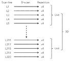
- the three-dimensional scan of this example is executed for 320 scan lines L1 to L320.
- One B scan consists of 320 A scans (see FIG. 4A).
- the A scan is a scan for one A line. That is, the A scan is a scan with respect to the A line along the incident direction (z direction, depth direction) of the measurement light LS.
- the B scan includes 320 A line scans arranged along the scan line Li on the xy plane orthogonal to the z direction.
- the B scan for the scan lines L1 to L320 is executed four times according to the arrangement order.
- Four B scans for each scan line Li are called repetition scans.
- the scan lines L1 to L320 are classified into groups of five according to the arrangement order.
- a set of 64 obtained by this classification is called a unit, and a scan for each unit is called a unit scan.
- the unit scan consists of four B scans for each of the five scan lines (that is, a total of 20 B scans).
- the abnormality detection process in this example is executed for each unit. If no abnormality is detected during the three-dimensional scan, 320 ⁇ 4 ⁇ 5 ⁇ 64 A scans are executed in the temporal order shown in FIG. 4A, and 4 ⁇ 5 ⁇ 64 B scan images are acquired. If an abnormality is detected, the unit is scanned again when the abnormality occurs, as will be described later.
- (1) to (3) are detected based on the OCT data, and (4) and (5) are detected based on the front image (fundus image).
- This embodiment has the following advantages by combining OCT and fundus imaging.
- the displacement amount of the eye to be examined cannot be obtained only by OCT, but in this embodiment, the scan position can be corrected (tracked) by obtaining the displacement amount by analyzing the front image.
- the OCT data analysis unit 231 detects the occurrence of abnormality by analyzing a series of data (interference signals) collected by one unit scan.
- the OCT data analysis unit 231 analyzes each A scan data (interference signal) included in each B scan data, and obtains a feature value representing the characteristic of the signal waveform. This feature value is, for example, the number of predetermined feature points in the signal waveform.
- This feature point is, for example, a turning point in the signal waveform (a point where an extreme value is taken, for example, a peak point protruding upward), or a point where the amplitude is zero (zero cross point).
- the OCT data analysis unit 231 identifies feature points in the A scan data and counts the number of the feature points. The above processing is executed for each of 320 pieces of A scan data included in the B scan data. Thereby, 320 feature values related to the B scan are obtained. A set of these 320 feature values is referred to as B-scan characteristic information. Such processing is executed for each of the 20 B scan data obtained by the unit scan. Thereby, 20 pieces of characteristic information regarding the unit scan are obtained. Further, the OCT data analysis unit 231 calculates an error between the two pieces of characteristic information, and detects the presence / absence of an abnormality based on the error. The error calculated here is, for example, a correlation coefficient or a mean square error.
- the OCT data analysis unit 231 calculates correlation coefficients of a plurality of pairs including different combinations of four characteristic information based on the repetition scan of this scan line. calculate.
- the plurality of pairs considered here are, for example, a pair of first characteristic information and second characteristic information, a pair of second characteristic information and third characteristic information, and third characteristic information and fourth characteristic information. It is a pair.
- the OCT data analysis unit 231 determines whether the calculated correlation coefficient is less than a predetermined threshold. If the correlation coefficient is less than the threshold value, it is determined that blinking has occurred during the repetition scan of this scan line.
- the interference signal acquired during blinking is only a noise component, and the correlation coefficient is almost zero.
- the above blink detection is a process using such a phenomenon.
- the correlation coefficient can be applied instead of the mean square error. Further, unlike the following (3), which requires 20 B scan data obtained by one unit scan, since this detection process (2) uses only a part of it, it is possible to detect fixation disparity at an early stage. There is. It is also possible to configure to execute only one of the detection processes (2) and (3).
- the OCT data analysis unit 231 has a plurality of pairs of different combinations of four characteristic information based on the repetition scan of this scan line.
- Each of the mean square errors is calculated, and the maximum value and the minimum value among the plurality of calculated mean square errors are specified.
- the plurality of pairs considered here are, for example, all combinations that select two from four pieces of characteristic information.
- the OCT data analysis unit 231 specifies the maximum value and the minimum value from the five maximum values and the five minimum values specified for the five scan lines that are the target of this unit scan.
- the maximum value and the minimum value specified here are the maximum value of the five maximum values and the minimum value of the five minimum values, respectively.
- the OCT data analysis unit 231 calculates the difference between the maximum value and the minimum value corresponding to this unit scan, and determines whether this difference exceeds a predetermined threshold value. When the difference exceeds the threshold value, it is determined that the eye E has been displaced (fixation shift has occurred) during this unit scan.
- the maximum value of the mean square error is obtained in consideration of all combinations (six) pairs of the four pieces of characteristic information.
- the present invention is not limited to this.
- any of the four B scans included in the repetition scan can be regarded as a scan for redundancy, and the maximum value can be obtained by excluding the B scan that gives an outlier. Since the repetition scan is performed in an extremely short time, it is considered that the factor that deteriorates the value of the mean square error is not fixation disparity but noise. According to this modification, it is possible to prevent erroneous detection of abnormality due to noise mixing.
- Imaging Data Analysis Unit 232 An example of processing executed by the imaging data analysis unit 232 will be described. As described above, the imaging data analysis unit 232 detects an abnormality by analyzing two or more fundus images including one or more fundus images acquired by the fundus camera unit 2 corresponding to the unit scan.
- the two or more fundus images to be analyzed include at least one fundus image acquired from the start to the end of this unit scan.
- an infrared fundus observation image is acquired in parallel with the above three-dimensional scan.
- the infrared fundus observation image is a moving image having a predetermined frame rate.
- the frame rate is set so that at least one frame is obtained during each unit scan.
- the frame rate of the infrared fundus observation image and the OCT scan conditions are at least for each unit scan. It is set so that one frame can be obtained.
- the imaging data analysis unit 232 analyzes two front images (frames of infrared fundus observation images) acquired at different timings, thereby determining the displacement amount (displacement direction) of the fundus oculi Ef depicted in these front images. Calculated).
- pattern matching such as a normalized correlation method or a phase only correlation method (POC) is used as in the conventional case.
- One of the two frames to be compared is, for example, a reference image (baseline image) acquired at the start of imaging (for example, at the start of OCT scan).
- the imaging data analysis unit 232 calculates the amount of displacement between the newly acquired front image (the frame acquired during a certain unit scan) and this reference image.
- the amount of displacement of the fundus oculi Ef can be obtained, for example, when the range of the fundus oculi Ef depicted in the two front images are completely different or out of focus. There is a case that cannot be done.
- the following processing can be executed.
- the imaging data analysis unit 232 obtains a normalized correlation value between the newly acquired front image and the reference image. If the normalized correlation value is less than a predetermined threshold, it is determined that an abnormality has occurred.
- a phase image representing a temporal change in phase between a plurality of B scan images obtained by repetition scanning can be created, and the correlation between such phase images can be used.
- a fundus image (such as the above-described captured image) obtained by flashing visible light or a fluorescent image.
- Threshold value used for determination of correlation value is set by an arbitrary method.
- a threshold value can be set in consideration of a low correlation value in an eye to be examined in which opacity occurs due to cataracts or the like. Further, when an abnormality is detected a predetermined number of times in this detection process (4) (when an error is determined), the threshold value can be decreased continuously or stepwise.
- the imaging data analysis unit 232 can calculate the amount of displacement between the two front images (the amount of displacement of the eye E). This process is executed, for example, when the occurrence of displacement is detected by the OCT data analysis unit 231. As a result, while detecting the occurrence of displacement using the OCT data, the amount of detected displacement can be obtained from the infrared fundus observation image or the like.
- the main control unit 211 can feed back the calculated displacement amount to the OCT scan.
- the storage unit 212 stores control information of the optical scanner 42 when the reference image is acquired and control information of the optical scanner 42 in each unit scan.
- the control information includes, for example, a coordinate group corresponding to the B scan.
- the main control unit 211 can correct the control information with the amount of displacement calculated by the imaging data analysis unit 232, and use the corrected control information to re-execute the unit scan in which the displacement is detected. Further, it is possible to obtain a displacement amount between the latest front image and the reference image and reflect this in the control information to execute the unit scan.
- an abnormality is detected by obtaining a displacement amount between the front image and the reference image corresponding to the unit scan and determining whether a difference between the displacement amount and the control information (coordinate group) is equal to or greater than a predetermined threshold.
- the threshold value at this time is set to 0.5 pixels, 0.7 pixels, or 1.0 pixels, for example.
- Preparation for shooting First, preparation for shooting is performed.
- the examiner activates the ophthalmologic imaging apparatus 1 and operates a key (graphical user interface icon or the like) for executing the above three-dimensional scan
- the main control unit 211 observes the fundus oculi Ef with the live OCT image. For this purpose is displayed on the display unit 241.
- the examiner moves the apparatus main body (fundus camera unit 2 or the like) in a direction away from the chin rest or the like using the operation unit 242 (for example, a joystick). Thereby, the anterior segment can be observed.
- the main control unit 211 turns on the observation light source 11 and causes the display unit 241 to display an observation image (anterior eye portion observation image) based on the output from the image sensor 35.
- the examiner (or the ophthalmologic photographing apparatus 1) adjusts the position of the apparatus main body so that the pupil is drawn at the center of the frame of the observation image.
- the examiner (or the ophthalmologic photographing apparatus 1) moves the apparatus main body closer to the eye E to be examined. Thereby, the observation target is switched from the anterior segment to the fundus oculi Ef, and an observation image of the fundus oculi Ef is displayed on the display unit 241.
- the main controller 211 controls the alignment optical system 50 to start projecting the alignment index (two alignment bright spots). Two alignment bright spot images are drawn on the observation image.
- the examiner or the ophthalmologic photographing apparatus 1) adjusts the position of the apparatus main body so that two alignment bright spot images are drawn in a target (such as a parenthesis mark) presented at the center of the frame.
- the main controller 211 controls the focus optical system 60 to start projecting the split index.
- adjustment of the optical path length for example, adjustment of the position of at least one of the optical path length changing unit 41 and the corner cube 114
- adjustment of the polarization state for example, control of at least one of the polarization controllers 103 and 118
- Adjustment of the amount of light for example, control of the attenuator 120
- adjustment of the focus for example, adjustment of the position of the OCT focusing lens 43
- the like are performed.
- the examiner (or the ophthalmologic photographing apparatus 1) confirms that problems such as flare mixing have not occurred in the observed image.
- the examiner uses the operation unit 242 to perform an operation for starting imaging.
- the main control unit 211 can overlay an image representing the current scan position by OCT on the observation image.
- the main control unit 211 registers the frame (front image) of the observation image obtained at this stage as a reference image.
- the imaging data analysis unit 232 starts processing for detecting a displacement between the reference image and a frame acquired thereafter. When the displacement exceeds the threshold due to the effect of blinking or fixation disparity or when the displacement cannot be detected, the main control unit 211 registers the newly acquired frame as a new reference image.
- the imaging data analysis unit 232 sequentially calculates the displacement between the frame acquired thereafter and the reference image.
- the main control unit 211 corrects the orientation of the optical scanner 42 so as to cancel the sequentially calculated displacement. This process may be executed in the same manner as in conventional tracking. The correction of the orientation of the optical scanner 42 is not performed while one repetition scan is being performed, but is performed after the completion.
- the method and timing for registering the reference image are not limited to this.
- the reference image can be registered by any method at any timing of the subsequent processing.
- the main control unit 211 determines a scan position (imaging position) by OCT. At the stage immediately after the start of imaging, a range to be subjected to three-dimensional scanning is set. Reference is now made to FIG. Reference symbol F indicates a frame of the observation image, and reference symbol R indicates a scan area of the three-dimensional scan.
- the scan area R is divided into 64 unit scan areas U1 to U64.
- the unit scan areas U1 to U64 correspond to the unit scans “# 1 Unit scan” to “# 64 Unit scan” shown in FIG. 4A, respectively. This scan area R is set immediately after the start of photographing.
- the main control unit 211 performs an OCT scan based on the imaging position determined in step S12. Immediately after the start of imaging, the three-dimensional scan for the scan area R is started from the scan for the first unit scan area U1 (“# 1 Unit scan” shown in FIG. 4A). In parallel with OCT, infrared moving image photographing of the fundus oculi Ef is executed at a predetermined frame rate.
- the main control unit 211 sends the data collected by the OCT scan for one unit scan area in step S13 and the frame of the observation image acquired in parallel with this unit scan to the data processing unit 230.
- the data processing unit 230 collects the OCT data for 20 B scans collected in the first unit scan (“# 1 Unit scan”) for the first unit scan area U1 and the first unit. An observation image frame acquired in parallel with the scan is acquired. Note that the OCT scan and infrared moving image shooting started in step S13 are executed in parallel with the abnormality detection processing in steps S21 to S25.
- the OCT data analysis unit 231 executes processing for detecting occurrence of an abnormality such as displacement or blinking of the eye E.
- the OCT data analysis unit 231 executes any of the detection processes (1) to (3) described above.
- the imaging data analysis unit 232 detects the occurrence of abnormality by executing, for example, the detection process (4).
- step S23 Has the occurrence of abnormality been detected If no abnormality is detected in step S22 (S23: No), that is, if it is determined that no abnormality has occurred during the unit scan, the process proceeds to step S25. On the other hand, when an abnormality that has occurred during the unit scan is detected (S23: Yes), the process proceeds to step S24.
- step S24 The amount of abnormality is detected
- the imaging data analysis unit 232 executes, for example, the detection process (5), thereby the amount of displacement of the eye E (displacement direction and displacement amount). Ask for. Then, the process proceeds to step S25.
- the abnormality detection process in steps S22 to S24 is executed as follows, for example.
- the detection process (1) is executed.
- the OCT data analysis unit 231 obtains the above-described characteristic information based on the OCT data obtained by the first four B scans of the unit scan, and calculates their correlation coefficients. If this correlation coefficient is less than the threshold value, it is determined that an abnormality has occurred, and other processing for detecting the occurrence of the abnormality is skipped, and the process proceeds to step S24.
- the process proceeds to the detection process (2). Specifically, the OCT data analysis unit 231 calculates the mean square error of each of the six pairs including all combinations of the four characteristic information based on the repetition scan, and determines whether the mean square error exceeds a threshold value. To do. If the mean square error exceeds the threshold value, it is determined that an abnormality has occurred, and other processing for detecting the occurrence of the abnormality is skipped, and the process proceeds to step S24. At this time, the maximum value and the minimum value of the mean square error are held.
- the detection processes (1) and (2) are executed for the four B scan data corresponding to the other scan lines included in the unit scan.
- the process proceeds to the detection process (3).
- the OCT data analysis unit 231 specifies the maximum value and the minimum value from the five maximum values and the five minimum values specified for the five scan lines that are the target of the unit scan, and these Calculate the difference. If this difference exceeds the threshold, it is determined that an abnormality has occurred, and other processing for detecting the occurrence of the abnormality is skipped and the process proceeds to step S24.
- the last B scan of the unit scan (20th B scan) Can be adopted as a reference image.
- the process proceeds to the detection process (4).
- the imaging data analysis unit 232 applies a normalized correlation method or a phase-only correlation method to each of the frames acquired during the unit scan and the reference image (or the phase image). The occurrence of an abnormality is detected by executing the correlation calculation of the above. If no abnormality is detected in any of the detection processes (1) to (4) (S23: No), the process proceeds to step S25.
- a difference between a plurality of displacements is calculated; whether or not the difference is deviated by at least one of a threshold value (for example, 0.5 pixel) in at least one of the x direction and the y direction (considering a correction amount of the scan position by tracking) Yes: If it is determined that the difference is greater than or equal to the threshold, it is determined that an abnormality has occurred.
- a threshold value for example, 0.5 pixel
- step S24 for example, the detection process (5) is executed. Specifically, the imaging data analysis unit 232 calculates the amount of displacement between the frame of the observation image and the reference image.
- the abnormality detection result acquired by the data processing unit 230 is stored in the storage unit 212.
- occurrence of abnormality is not detected in step S22 (S23: No), information indicating that is stored as a detection result.
- step S22 when the occurrence of an abnormality is detected in step S22 (S23: No) and the amount of this abnormality is detected (S24), for example, information indicating that an abnormality has been detected, the type of abnormality detected , Information indicating the amount of detected abnormality, and the like are stored as detection results.
- the main control unit 211 confirms (refers to) the detection result stored in step S25 and recognizes the presence / absence of an abnormality and the amount thereof.
- step S15: No abnormality If no abnormality is detected (S15: Yes), the process proceeds to step S16. On the other hand, when an abnormality is detected (S15: No), the process returns to step S12. At this time, the photographing position is determined so as to return the scan position to the first position of the unit scan where the abnormality is detected (S12). In addition, the photographing position can be corrected so as to cancel the detected displacement.
- the process returns to step S12.
- the unit scan area next to the unit scan area of the unit scan (or the unit scan area next to the unit scan area where the unit scan is currently being executed) is set as the imaging position (S12).
- the photographing position can be corrected so as to cancel the detected displacement.
- step S17 If the unit scan is an OCT scan of the last unit scan area U64 (S16: Yes), the process proceeds to step S17.
- an abnormality is detected in the last unit scan (“# 64 Unit scan” shown in FIG. 4A) (S17: No) (S17: No) (S17: No) (S17: No) (S17: No) (S17: No) (S17: No) (S17: No) (S17: No)
- the process returns to step S12. At this time, the photographing position is determined so as to return the scan position to the first position of the last unit scan (S12). In addition, the photographing position can be corrected so as to cancel the detected displacement.
- the ophthalmic imaging apparatus includes a data collection unit, an imaging unit, a control unit, and an abnormality detection unit.
- the data collection unit collects data by scanning the eye to be examined using optical coherence tomography (OCT).
- OCT optical coherence tomography
- the data collection unit includes, for example, the OCT unit 100 and elements in the fundus camera unit 2 that form a measurement optical path.
- the imaging unit captures the eye to be examined and acquires a front image.
- the photographing unit includes, for example, an illumination optical system 10 and a photographing optical system 30.
- the control unit controls the data collection unit to perform a series of scans along a preset route group.
- the control unit includes a main control unit 211, for example.
- a unit scan along a path group consisting of five scan lines is executed as this series of scans.
- the abnormality detection unit detects an abnormality based on a series of data collected by a series of scans and two or more front images including one or more front images acquired by the imaging unit corresponding to the series of scans. To do.
- One of the two or more front images may be a reference image.
- the detection of abnormality may include at least one of detection of occurrence of abnormality and detection of the amount of abnormality.
- the embodiment configured as described above it is possible to detect the movement and blink of the eye to be examined using an OCT scan whose repetition rate is sufficiently higher than the frame rate of the video camera. Further, it is possible to detect the movement of the eye to be examined and the occurrence of blinking, and the amount of movement of the eye to be examined from the front image. Therefore, it is possible to obtain an OCT image with high accuracy even when the eye to be examined moves or blinks.
- the abnormality detection unit includes a first abnormality detection unit that detects occurrence of an abnormality based on a series of data collected by a series of scans using OCT, and two or more front images obtained by the imaging unit. And a second abnormality detection unit that detects the amount of abnormality based on the above.
- the first abnormality detection unit includes an OCT data analysis unit 231
- the second abnormality detection unit includes an imaging data analysis unit 232.
- the second abnormality detection unit may be configured to detect the amount of the abnormality.
- a series of scans using the OCT may include scans (repetition scans) that are sequentially executed a predetermined number of times with respect to the path group.
- the series of data may include a predetermined number of data sets (a plurality of B scan data obtained by repetition scanning of each scan line) corresponding to each path included in the path group.
- the first abnormality detection unit may be configured to obtain characteristic information of each of a predetermined number of data sets and detect occurrence of an abnormality based on the characteristic information.
- the first anomaly detection unit calculates and calculates each error (mean square error, etc.) of a plurality of pairs made up of different combinations of a predetermined number of characteristic information for each path of the path group.
- a maximum value and a minimum value of the plurality of errors may be specified.
- the first abnormality detection unit detects an abnormality during the series of scans when a difference between the maximum value and the minimum value among the plurality of maximum values and the plurality of minimum values specified for the path group exceeds a threshold value. Can be determined to have occurred.
- An example of this process is the detection process (3) in the above embodiment.
- the first abnormality detection unit is configured to calculate an error (such as a mean square error) of each of a plurality of pairs including different combinations of a predetermined number of characteristic information for each of the routes in the route group. Good. Furthermore, when the calculated error exceeds the threshold, the first abnormality detection unit can determine that an abnormality has occurred during the scan for the path.
- an error such as a mean square error
- the first abnormality detection unit can determine that an abnormality has occurred during the scan for the path.
- An example of this process is the detection process (2) in the above embodiment.
- the first abnormality detection unit calculates a correlation coefficient of a plurality of pairs including different combinations of a predetermined number of characteristic information for each path of the path group, and the calculated correlation coefficient is less than a threshold value. If so, it may be configured to determine that an abnormality has occurred during the scan for the path.
- An example of this process is the detection process (1) in the above embodiment.
- the first abnormality detection unit is configured to store, for each of the predetermined number of data sets (a plurality of B scan data obtained by repetition scanning of each scan line), a plurality of A scan data included in the data set. Each of them may be analyzed to obtain a feature value representing the feature of the signal waveform, and the characteristic information may be obtained based on the plurality of obtained feature values.
- This feature value may be the number of predetermined feature points in this signal waveform. This feature point may be an extreme point or a zero cross point.
- the second abnormality detection unit may be configured to detect a displacement between two or more front images as an amount of abnormality. Furthermore, the second abnormality detection unit can calculate the displacement between two or more front images using the phase only correlation method.
- the abnormality detection unit may include a third abnormality detection unit that detects the occurrence of abnormality based on the front image.
- the third abnormality detection unit calculates a correlation coefficient between two or more front images, and when this correlation coefficient is less than a threshold, an abnormality (displacement of the eye to be examined, focus shift) is detected during scanning with respect to the path. Etc.).
- An example of this process is the detection process (4) in the above embodiment.
- the imaging data analysis unit 232 is an example of a third abnormality detection unit.
- the control unit when an abnormality is detected by the abnormality detection unit (that is, when an abnormality occurs or when the amount of abnormality is large), the control unit performs a series of scans performed when the abnormality occurs.
- the data collection unit can be controlled to perform again. As a result, the area that was being scanned when the abnormality occurred can be scanned again to reacquire data.
- control unit can control the data collection unit to sequentially perform a series of scans on a plurality of preset route groups.
- the abnormality detection unit can perform the above-described abnormality detection for each route group.
- abnormality detection is performed for each unit scan area while performing unit scans sequentially on 64 unit scan areas. This makes it possible to acquire a highly accurate three-dimensional OCT image (volume data or the like) even when the eye to be examined moves or blinks.
Abstract
The ophthalmologic imaging apparatus pertaining to an embodiment of the present invention is provided with a data collecting unit, an imaging unit, a control unit, and an abnormality sensing unit. The data collecting unit collects data by scanning a subject eye using optical coherence tomography. The imaging unit captures an image of the subject eye and acquires a front image. The control unit controls the data collecting unit so that a series of scans is performed along a pre-set path group. The abnormality sensing unit senses an abnormality on the basis of a series of data collected by a series of scans and two or more front images including one or more front images acquired by the imaging unit in accordance with the series of scans.
Description
本発明は、光コヒーレンストモグラフィ(OCT)を利用して被検眼を画像化する眼科撮影装置に関する。
The present invention relates to an ophthalmologic photographing apparatus that images an eye to be examined using optical coherence tomography (OCT).
眼科分野において画像診断は重要な位置を占める。近年ではOCTの活用が進んでいる。OCTは、被検眼のBモード画像や3次元画像の取得だけでなく、Cモード画像やシャドウグラムなどの正面画像(en-face画像)の取得にも利用されるようになってきている。また、被検眼の特定部位を強調した画像を取得することや、機能情報を取得することも行われている。例えば、OCTにより収集された時系列データに基づいて、網膜血管や脈絡膜血管が強調された画像(アンギオグラム)を構築することができる。更に、OCTにより収集された時系列データにおける位相情報から血流情報(血流速度、血流量等)を求めることも可能である。このような画像化技術は、例えば特許文献1-3に開示されている。また、同一断面を繰り返しスキャンして複数の画像を取得し、これらを加算平均して低ノイズの画像を作成する技術も知られている(例えば特許文献4を参照)。
Diagnostic imaging occupies an important position in the ophthalmology field. In recent years, the use of OCT has progressed. OCT has been used not only for acquiring B-mode images and three-dimensional images of the eye to be examined, but also for acquiring front images (en-face images) such as C-mode images and shadowgrams. Moreover, acquiring the image which emphasized the specific site | part of the eye to be examined, and acquiring functional information are also performed. For example, an image (angiogram) in which retinal blood vessels and choroidal blood vessels are emphasized can be constructed based on time-series data collected by OCT. Furthermore, blood flow information (blood flow velocity, blood flow volume, etc.) can be obtained from phase information in time-series data collected by OCT. Such an imaging technique is disclosed in, for example, Patent Documents 1-3. A technique is also known in which a plurality of images are acquired by repeatedly scanning the same cross section, and these are averaged to create a low noise image (see, for example, Patent Document 4).
上記のような画像化技術では3次元スキャンや繰り返しスキャンが適用される。3次元スキャンや繰り返しスキャンには、数秒から十秒程度、場合によってはそれ以上の時間が掛かる。そのため、スキャン中に被検眼の位置がずれたり瞬きが発生したりするおそれがある。このような問題に鑑み、トラッキングや再スキャンが利用されている。トラッキングは、スキャン中における被検眼の移動をビデオカメラで監視し、その移動に合わせて光スキャナをリアルタイムで制御する技術である(例えば特許文献5を参照)。再スキャンは、スキャン中における被検眼をビデオカメラで監視し、被検眼が大きく動いたタイミングや瞬きが発生したタイミングにてスキャンされた位置を再度スキャンする技術である(例えば特許文献6を参照)。
In the imaging technology as described above, 3D scanning and repeated scanning are applied. Three-dimensional scanning and repeated scanning take several seconds to about 10 seconds, and sometimes more. Therefore, there is a possibility that the position of the eye to be inspected or blinking may occur during scanning. In view of such problems, tracking and rescanning are used. Tracking is a technique for monitoring the movement of an eye to be examined during scanning with a video camera and controlling the optical scanner in real time according to the movement (see, for example, Patent Document 5). The rescan is a technique of monitoring the eye under examination with a video camera and rescanning the scanned position at the timing when the eye to be moved largely or the timing of blinking (see, for example, Patent Document 6). .
従来のトラッキングや再スキャンでは、ビデオカメラによる映像を解析して被検眼の移動や瞬きを検知している。一方、近年のOCT技術の進歩によって、OCTスキャンの繰り返しレート(例えばBスキャンの反復レート)は、ビデオカメラのフレームレートよりもかなり高くなっている。例えば、典型的なBスキャンの反復間隔が2~3ms程度であるのに対し、ビデオカメラのフレームレートは20~50FPS程度(フレーム間隔20~50ms程度)である。そのため、ビデオカメラでは検知できない被検眼の移動等がOCT画像に影響を与えることがある。また、被検眼の移動等の影響を受けたスキャンを特定できないこと、当該スキャンの特定に時間が掛かること、といった問題もある。なお、被検眼の移動等を検知する間隔を短くすることも考えられるが、非常に高価な撮影装置が必要となるため現実的ではない。
In conventional tracking and rescanning, the video from the video camera is analyzed to detect movement and blinking of the eye to be examined. On the other hand, due to recent advances in OCT technology, the repetition rate of OCT scans (for example, the repetition rate of B scans) is much higher than the frame rate of video cameras. For example, while the typical B-scan repetition interval is about 2 to 3 ms, the frame rate of the video camera is about 20 to 50 FPS (frame interval about 20 to 50 ms). For this reason, movement of the eye to be examined which cannot be detected by the video camera may affect the OCT image. In addition, there is a problem that a scan affected by the movement of the eye to be examined cannot be specified, and it takes time to specify the scan. Although it is conceivable to shorten the interval for detecting the movement or the like of the eye to be examined, it is not realistic because a very expensive imaging device is required.
本発明の目的は、被検眼の移動や瞬きが発生した場合でも高確度のOCT画像を取得可能な眼科撮影装置を提供することにある。
An object of the present invention is to provide an ophthalmologic imaging apparatus capable of acquiring a highly accurate OCT image even when a subject's eye moves or blinks.
実施形態の眼科撮影装置は、データ収集部、撮影部、制御部、及び異常検知部を備える。データ収集部は、光コヒーレンストモグラフィを用いて被検眼をスキャンすることによりデータを収集する。撮影部は、被検眼を撮影して正面画像を取得する。制御部は、予め設定された経路群に沿って一連のスキャンを行うようにデータ収集部を制御する。異常検知部は、一連のスキャンにより収集された一連のデータと、一連のスキャンに対応して撮影部により取得された1以上の正面画像を含む2以上の正面画像とに基づいて、異常を検知する。
The ophthalmic imaging apparatus according to the embodiment includes a data collection unit, an imaging unit, a control unit, and an abnormality detection unit. The data collection unit collects data by scanning the eye to be examined using optical coherence tomography. The imaging unit captures the eye to be examined and acquires a front image. The control unit controls the data collection unit to perform a series of scans along a preset route group. The abnormality detection unit detects an abnormality based on a series of data collected by a series of scans and two or more front images including one or more front images acquired by the imaging unit corresponding to the series of scans. To do.
実施形態に係る眼科撮影装置によれば、被検眼の移動や瞬きが発生した場合でも高確度のOCT画像を取得可能である。
According to the ophthalmologic photographing apparatus according to the embodiment, it is possible to acquire a highly accurate OCT image even when the eye to be examined moves or blinks.
本発明の幾つかの実施形態について図面を参照しながら詳細に説明する。実施形態は、光干渉断層計(OCT)としての機能と、被検眼の正面画像を取得する機能とを備える眼科撮影装置である。後者の機能は、例えば、眼底カメラ、走査型レーザ検眼鏡(SLO)、スリットランプ顕微鏡、眼科手術用顕微鏡、前眼部撮影カメラ等により実現可能である。以下、スウェプトソースOCTと眼底カメラとを組み合わせた例を説明するが、実施形態はこれに限定されない。
Several embodiments of the present invention will be described in detail with reference to the drawings. The embodiment is an ophthalmologic photographing apparatus having a function as an optical coherence tomography (OCT) and a function of acquiring a front image of an eye to be examined. The latter function can be realized by, for example, a fundus camera, a scanning laser ophthalmoscope (SLO), a slit lamp microscope, an ophthalmic surgical microscope, an anterior ocular segment imaging camera, or the like. Hereinafter, an example in which the swept source OCT and the fundus camera are combined will be described, but the embodiment is not limited thereto.
〈構成〉
図1に示すように、眼科撮影装置1は、眼底カメラユニット2、OCTユニット100及び演算制御ユニット200を含む。眼底カメラユニット2には、被検眼の正面画像を取得するための光学系や機構が設けられている。OCTユニット100には、OCTを実行するための光学系や機構が設けられている。演算制御ユニット200は、各種の演算及び制御を実行するプロセッサを含む。これらに加え、被検者の顔を支持するための部材(顎受け、額当て等)や、OCTの対象部位を切り替えるためのレンズユニット(例えば、前眼部OCT用アタッチメント)が設けられてもよい。 <Constitution>
As shown in FIG. 1, theophthalmologic photographing apparatus 1 includes a fundus camera unit 2, an OCT unit 100, and an arithmetic control unit 200. The fundus camera unit 2 is provided with an optical system and a mechanism for acquiring a front image of the eye to be examined. The OCT unit 100 is provided with an optical system and a mechanism for performing OCT. The arithmetic control unit 200 includes a processor that executes various arithmetic operations and controls. In addition to these, a member for supporting the subject's face (chin rest, forehead rest, etc.) and a lens unit (for example, an anterior ocular segment OCT attachment) for switching an OCT target site may be provided. Good.
図1に示すように、眼科撮影装置1は、眼底カメラユニット2、OCTユニット100及び演算制御ユニット200を含む。眼底カメラユニット2には、被検眼の正面画像を取得するための光学系や機構が設けられている。OCTユニット100には、OCTを実行するための光学系や機構が設けられている。演算制御ユニット200は、各種の演算及び制御を実行するプロセッサを含む。これらに加え、被検者の顔を支持するための部材(顎受け、額当て等)や、OCTの対象部位を切り替えるためのレンズユニット(例えば、前眼部OCT用アタッチメント)が設けられてもよい。 <Constitution>
As shown in FIG. 1, the
本明細書において「プロセッサ」は、例えば、CPU(Central Processing Unit)、GPU(Graphics Processing Unit)、ASIC(Application Specific Integrated Circuit)、プログラマブル論理デバイス(例えば、SPLD(Simple Programmable Logic Device)、CPLD(Complex Programmable Logic Device)、FPGA(Field Programmable Gate Array))等の回路を意味する。プロセッサは、例えば、記憶回路や記憶装置に格納されているプログラムを読み出し実行することで、実施形態に係る機能を実現する。
In this specification, the “processor” is, for example, a CPU (Central Processing Unit), a GPU (Graphics Processing Unit), an ASIC (Application Specific Integrated Circuit), a programmable logic device (eg, SPLD (Simple ProGLD). It means a circuit such as Programmable Logic Device (FPGA) or Field Programmable Gate Array (FPGA). For example, the processor implements the functions according to the embodiment by reading and executing a program stored in a storage circuit or a storage device.
〈眼底カメラユニット2〉
眼底カメラユニット2には、被検眼Eの眼底Efを撮影するための光学系が設けられている。取得される眼底Efの画像(眼底像、眼底写真等と呼ばれる)は、観察画像、撮影画像等の正面画像である。観察画像は、近赤外光を用いた動画撮影により得られる。撮影画像は、フラッシュ光を用いた静止画像である。 <Fundus camera unit 2>
Thefundus camera unit 2 is provided with an optical system for photographing the fundus oculi Ef of the eye E to be examined. The acquired image of the fundus oculi Ef (referred to as a fundus oculi image, a fundus oculi photo, or the like) is a front image such as an observation image or a captured image. The observation image is obtained by moving image shooting using near infrared light. The photographed image is a still image using flash light.
眼底カメラユニット2には、被検眼Eの眼底Efを撮影するための光学系が設けられている。取得される眼底Efの画像(眼底像、眼底写真等と呼ばれる)は、観察画像、撮影画像等の正面画像である。観察画像は、近赤外光を用いた動画撮影により得られる。撮影画像は、フラッシュ光を用いた静止画像である。 <
The
眼底カメラユニット2は、照明光学系10と撮影光学系30とを含む。照明光学系10は被検眼Eに照明光を照射する。撮影光学系30は、被検眼Eからの照明光の戻り光を検出する。OCTユニット100からの測定光は、眼底カメラユニット2内の光路を通じて被検眼Eに導かれ、その戻り光は、同じ光路を通じてOCTユニット100に導かれる。
The fundus camera unit 2 includes an illumination optical system 10 and a photographing optical system 30. The illumination optical system 10 irradiates the eye E with illumination light. The imaging optical system 30 detects the return light of the illumination light from the eye E. The measurement light from the OCT unit 100 is guided to the eye E through the optical path in the fundus camera unit 2, and the return light is guided to the OCT unit 100 through the same optical path.
照明光学系10の観察光源11から出力された光(観察照明光)は、曲面状の反射面を有する反射ミラー12により反射され、集光レンズ13を経由し、可視カットフィルタ14を透過して近赤外光となる。更に、観察照明光は、撮影光源15の近傍にて一旦集束し、ミラー16により反射され、リレーレンズ17、18、絞り19及びリレーレンズ20を経由する。そして、観察照明光は、孔開きミラー21の周辺部(孔部の周囲の領域)にて反射され、ダイクロイックミラー46を透過し、対物レンズ22により屈折されて被検眼E(眼底Ef又は前眼部)を照明する。被検眼Eからの観察照明光の戻り光は、対物レンズ22により屈折され、ダイクロイックミラー46を透過し、孔開きミラー21の中心領域に形成された孔部を通過し、ダイクロイックミラー55を透過し、撮影合焦レンズ31を経由し、ミラー32により反射される。更に、この戻り光は、ハーフミラー33Aを透過し、ダイクロイックミラー33により反射され、集光レンズ34によりイメージセンサ35の受光面に結像される。イメージセンサ35は、所定のフレームレートで戻り光を検出する。なお、撮影光学系30のフォーカスは眼底Ef又は前眼部に対して調整される。
The light (observation illumination light) output from the observation light source 11 of the illumination optical system 10 is reflected by the reflection mirror 12 having a curved reflecting surface, passes through the condensing lens 13 and passes through the visible cut filter 14. Near infrared light. Further, the observation illumination light is once converged in the vicinity of the photographing light source 15, reflected by the mirror 16, and passes through the relay lenses 17 and 18, the diaphragm 19 and the relay lens 20. The observation illumination light is reflected by the peripheral part of the perforated mirror 21 (area around the perforated part), passes through the dichroic mirror 46, and is refracted by the objective lens 22 to be examined eye E (fundus Ef or anterior eye). Part). The return light of the observation illumination light from the eye E is refracted by the objective lens 22, passes through the dichroic mirror 46, passes through the hole formed in the central region of the perforated mirror 21, and passes through the dichroic mirror 55. The light is reflected by the mirror 32 via the photographing focusing lens 31. Further, the return light passes through the half mirror 33A, is reflected by the dichroic mirror 33, and forms an image on the light receiving surface of the image sensor 35 by the condenser lens. The image sensor 35 detects return light at a predetermined frame rate. Note that the focus of the photographing optical system 30 is adjusted with respect to the fundus oculi Ef or the anterior eye segment.
撮影光源15から出力された光(撮影照明光)は、観察照明光と同様の経路を通って眼底Efに照射される。被検眼Eからの撮影照明光の戻り光は、観察照明光の戻り光と同じ経路を通ってダイクロイックミラー33まで導かれ、ダイクロイックミラー33を透過し、ミラー36により反射され、集光レンズ37によりイメージセンサ38の受光面に結像される。
The light (imaging illumination light) output from the imaging light source 15 is irradiated onto the fundus oculi Ef through the same path as the observation illumination light. The return light of the imaging illumination light from the eye E is guided to the dichroic mirror 33 through the same path as the return light of the observation illumination light, passes through the dichroic mirror 33, is reflected by the mirror 36, and is reflected by the condenser lens 37. An image is formed on the light receiving surface of the image sensor 38.
LCD39は固視標や視力測定用視標を表示する。LCD39から出力された光束は、その一部がハーフミラー33Aにて反射され、ミラー32に反射され、撮影合焦レンズ31及びダイクロイックミラー55を経由し、孔開きミラー21の孔部を通過する。孔開きミラー21の孔部を通過した固視光束は、ダイクロイックミラー46を透過し、対物レンズ22により屈折されて眼底Efに投射される。
LCD39 displays a fixation target and a visual target for visual acuity measurement. A part of the light beam output from the LCD 39 is reflected by the half mirror 33 </ b> A, reflected by the mirror 32, passes through the hole of the perforated mirror 21 through the photographing focusing lens 31 and the dichroic mirror 55. The fixation light beam that has passed through the hole of the aperture mirror 21 passes through the dichroic mirror 46, is refracted by the objective lens 22, and is projected onto the fundus oculi Ef.
アライメント光学系50は、被検眼Eに対する光学系のアライメントに用いられるアライメント指標を生成する。LED51から出力されたアライメント光は、絞り52及び53並びにリレーレンズ54を経由し、ダイクロイックミラー55により反射され、孔開きミラー21の孔部を通過する。孔開きミラー21の孔部を通過した光は、ダイクロイックミラー46を透過し、対物レンズ22により被検眼Eに投射される。アライメント光の角膜反射光は、観察照明光の戻り光と同じ経路を通ってイメージセンサ35に導かれる。その受光像(アライメント指標像)に基づいてマニュアルアライメントやオートアライメントを実行できる。
The alignment optical system 50 generates an alignment index used for alignment of the optical system with respect to the eye E. The alignment light output from the LED 51 passes through the apertures 52 and 53 and the relay lens 54, is reflected by the dichroic mirror 55, and passes through the hole of the perforated mirror 21. The light that has passed through the hole of the perforated mirror 21 passes through the dichroic mirror 46 and is projected onto the eye E by the objective lens 22. The corneal reflection light of the alignment light is guided to the image sensor 35 through the same path as the return light of the observation illumination light. Manual alignment and auto-alignment can be executed based on the received light image (alignment index image).
フォーカス光学系60は、被検眼Eに対するフォーカス調整に用いられるスプリット指標を生成する。フォーカス光学系60は、撮影光学系30の光路(撮影光路)に沿った撮影合焦レンズ31の移動に連動して、照明光学系10の光路(照明光路)に沿って移動される。反射棒67は、照明光路に対して挿脱可能である。フォーカス調整を行う際には、反射棒67の反射面が照明光路に傾斜配置される。LED61から出力されたフォーカス光は、リレーレンズ62を通過し、スプリット指標板63により2つの光束に分離され、二孔絞り64を通過し、ミラー65により反射され、集光レンズ66により反射棒67の反射面に一旦結像されて反射される。更に、フォーカス光は、リレーレンズ20を経由し、孔開きミラー21に反射され、ダイクロイックミラー46を透過し、対物レンズ22により屈折されて眼底Efに投射される。フォーカス光の眼底反射光は、アライメント光の角膜反射光と同じ経路を通ってイメージセンサ35に導かれる。その受光像(スプリット指標像)に基づいてマニュアルアライメントやオートアライメントを実行できる。
The focus optical system 60 generates a split index used for focus adjustment on the eye E. The focus optical system 60 is moved along the optical path (illumination optical path) of the illumination optical system 10 in conjunction with the movement of the imaging focusing lens 31 along the optical path (imaging optical path) of the imaging optical system 30. The reflection bar 67 can be inserted into and removed from the illumination optical path. When performing the focus adjustment, the reflecting surface of the reflecting bar 67 is inclinedly arranged in the illumination optical path. The focus light output from the LED 61 passes through the relay lens 62, is separated into two light beams by the split indicator plate 63, passes through the two-hole aperture 64, is reflected by the mirror 65, and is reflected by the condenser lens 66 as a reflecting rod 67. The light is once imaged and reflected on the reflection surface. Further, the focus light passes through the relay lens 20, is reflected by the perforated mirror 21, passes through the dichroic mirror 46, is refracted by the objective lens 22, and is projected onto the fundus oculi Ef. The fundus reflected light of the focus light is guided to the image sensor 35 through the same path as the cornea reflected light of the alignment light. Manual alignment and auto alignment can be executed based on the received light image (split index image).
視度補正レンズ70及び71は、孔開きミラー21とダイクロイックミラー55との間の撮影光路に選択的に挿入可能である。視度補正レンズ70は、強度遠視を補正するためのプラスレンズ(凸レンズ)である。視度補正レンズ71は、強度近視を補正するためのマイナスレンズ(凹レンズ)である。
The diopter correction lenses 70 and 71 can be selectively inserted into the photographing optical path between the perforated mirror 21 and the dichroic mirror 55. The diopter correction lens 70 is a plus lens (convex lens) for correcting the intensity hyperopia. The diopter correction lens 71 is a minus lens (concave lens) for correcting intensity myopia.
ダイクロイックミラー46は、眼底撮影用の光路とOCT用の光路とを合成する。ダイクロイックミラー46は、OCTに用いられる波長帯の光を反射し、眼底撮影用の光を透過させる。OCT用の光路には、OCTユニット100側から順に、コリメータレンズユニット40、光路長変更部41、光スキャナ42、OCT合焦レンズ43、ミラー44、及びリレーレンズ45が設けられている。
The dichroic mirror 46 combines the optical path for fundus imaging and the optical path for OCT. The dichroic mirror 46 reflects light in a wavelength band used for OCT and transmits light for fundus photographing. In the optical path for OCT, a collimator lens unit 40, an optical path length changing unit 41, an optical scanner 42, an OCT focusing lens 43, a mirror 44, and a relay lens 45 are provided in this order from the OCT unit 100 side.
光路長変更部41は、図1に示す矢印の方向に移動可能とされ、OCT用の光路長を変更する。この光路長の変更は、眼軸長に応じた光路長補正や、干渉状態の調整などに利用される。光路長変更部41は、コーナーキューブと、これを移動する機構とを含む。
The optical path length changing unit 41 is movable in the direction of the arrow shown in FIG. 1, and changes the optical path length for OCT. This change in optical path length is used for optical path length correction according to the axial length, adjustment of the interference state, and the like. The optical path length changing unit 41 includes a corner cube and a mechanism for moving the corner cube.
光スキャナ42は、被検眼Eの瞳孔と光学的に共役な位置に配置される。光スキャナ42は、OCT用の光路を通過する測定光LSを偏向する。光スキャナ42は、例えば、2次元走査が可能なガルバノスキャナである。
The optical scanner 42 is disposed at a position optically conjugate with the pupil of the eye E to be examined. The optical scanner 42 deflects the measurement light LS passing through the optical path for OCT. The optical scanner 42 is, for example, a galvano scanner capable of two-dimensional scanning.
OCT合焦レンズ43は、OCT用の光学系のフォーカス調整を行うために、測定光LSの光路に沿って移動される。撮影合焦レンズ31の移動、フォーカス光学系60の移動、及びOCT合焦レンズ43の移動を連係的に制御することができる。
The OCT focusing lens 43 is moved along the optical path of the measurement light LS in order to adjust the focus of the optical system for OCT. The movement of the photographing focusing lens 31, the movement of the focus optical system 60, and the movement of the OCT focusing lens 43 can be controlled in a coordinated manner.
〈OCTユニット100〉
図2に例示するように、OCTユニット100には、スウェプトソースOCTを実行するための光学系が設けられている。この光学系は、波長可変光源(波長掃引型光源)からの光を測定光と参照光とに分割し、被検眼Eからの測定光の戻り光と参照光路を経由した参照光とを干渉させて干渉光を生成し、この干渉光を検出する干渉光学系を含む。干渉光学系により得られる検出結果(検出信号)は、干渉光のスペクトルを示す信号であり、演算制御ユニット200に送られる。 <OCT unit 100>
As illustrated in FIG. 2, theOCT unit 100 is provided with an optical system for executing the swept source OCT. This optical system divides the light from the wavelength tunable light source (wavelength sweep type light source) into the measurement light and the reference light, and causes the return light of the measurement light from the eye E to interfere with the reference light via the reference light path. An interference optical system that generates interference light and detects the interference light. A detection result (detection signal) obtained by the interference optical system is a signal indicating the spectrum of the interference light, and is sent to the arithmetic control unit 200.
図2に例示するように、OCTユニット100には、スウェプトソースOCTを実行するための光学系が設けられている。この光学系は、波長可変光源(波長掃引型光源)からの光を測定光と参照光とに分割し、被検眼Eからの測定光の戻り光と参照光路を経由した参照光とを干渉させて干渉光を生成し、この干渉光を検出する干渉光学系を含む。干渉光学系により得られる検出結果(検出信号)は、干渉光のスペクトルを示す信号であり、演算制御ユニット200に送られる。 <
As illustrated in FIG. 2, the
光源ユニット101は、例えば、出射光の波長を高速で変化させる近赤外波長可変レーザを含む。光源ユニット101から出力された光L0は、光ファイバ102により偏波コントローラ103に導かれてその偏光状態が調整される。更に、光L0は、光ファイバ104によりファイバカプラ105に導かれて測定光LSと参照光LRとに分割される。
The light source unit 101 includes, for example, a near-infrared wavelength tunable laser that changes the wavelength of emitted light at high speed. The light L0 output from the light source unit 101 is guided to the polarization controller 103 by the optical fiber 102 and its polarization state is adjusted. Further, the light L0 is guided to the fiber coupler 105 by the optical fiber 104 and is divided into the measurement light LS and the reference light LR.
参照光LRは、光ファイバ110によりコリメータ111に導かれて平行光束に変換され、光路長補正部材112及び分散補償部材113を経由し、コーナーキューブ114に導かれる。光路長補正部材112は、参照光LRの光路長と測定光LSの光路長とを合わせるよう作用する。分散補償部材113は、参照光LRと測定光LSとの間の分散特性を合わせるよう作用する。コーナーキューブ114は、参照光LRの入射方向に移動可能であり、それにより参照光LRの光路長が変更される。
The reference light LR is guided to the collimator 111 by the optical fiber 110, converted into a parallel light beam, and guided to the corner cube 114 via the optical path length correction member 112 and the dispersion compensation member 113. The optical path length correction member 112 acts to match the optical path length of the reference light LR and the optical path length of the measurement light LS. The dispersion compensation member 113 acts to match the dispersion characteristics between the reference light LR and the measurement light LS. The corner cube 114 is movable in the incident direction of the reference light LR, and thereby the optical path length of the reference light LR is changed.
コーナーキューブ114を経由した参照光LRは、分散補償部材113及び光路長補正部材112を経由し、コリメータ116によって平行光束から集束光束に変換され、光ファイバ117に入射する。光ファイバ117に入射した参照光LRは、偏波コントローラ118に導かれてその偏光状態が調整され、光ファイバ119によりアッテネータ120に導かれて光量が調整され、光ファイバ121によりファイバカプラ122に導かれる。
The reference light LR that has passed through the corner cube 114 is converted from a parallel light beam into a converged light beam by the collimator 116 via the dispersion compensation member 113 and the optical path length correction member 112, and enters the optical fiber 117. The reference light LR incident on the optical fiber 117 is guided to the polarization controller 118 and its polarization state is adjusted. The reference light LR is guided to the attenuator 120 by the optical fiber 119 and the amount of light is adjusted, and is guided to the fiber coupler 122 by the optical fiber 121. It is burned.
一方、ファイバカプラ105により生成された測定光LSは、光ファイバ127により導かれてコリメータレンズユニット40により平行光束に変換され、光路長変更部41、光スキャナ42、OCT合焦レンズ43、ミラー44及びリレーレンズ45を経由し、ダイクロイックミラー46により反射され、対物レンズ22により屈折されて被検眼Eに入射する。測定光LSは、被検眼Eの様々な深さ位置において散乱・反射される。被検眼Eからの測定光LSの戻り光は、往路と同じ経路を逆向きに進行してファイバカプラ105に導かれ、光ファイバ128を経由してファイバカプラ122に到達する。
On the other hand, the measurement light LS generated by the fiber coupler 105 is guided by the optical fiber 127 and converted into a parallel light beam by the collimator lens unit 40, and the optical path length changing unit 41, the optical scanner 42, the OCT focusing lens 43, and the mirror 44. Then, the light passes through the relay lens 45, is reflected by the dichroic mirror 46, is refracted by the objective lens 22, and enters the eye E to be examined. The measurement light LS is scattered and reflected at various depth positions of the eye E. The return light of the measurement light LS from the eye E travels in the reverse direction on the same path as the forward path, is guided to the fiber coupler 105, and reaches the fiber coupler 122 via the optical fiber 128.
ファイバカプラ122は、光ファイバ128を介して入射された測定光LSと、光ファイバ121を介して入射された参照光LRとを合成して(干渉させて)干渉光を生成する。ファイバカプラ122は、所定の分岐比(例えば1:1)で干渉光を分岐することにより、一対の干渉光LCを生成する。一対の干渉光LCは、それぞれ光ファイバ123及び124を通じて検出器125に導かれる。
The fiber coupler 122 combines (interferences) the measurement light LS incident through the optical fiber 128 and the reference light LR incident through the optical fiber 121 to generate interference light. The fiber coupler 122 generates a pair of interference light LC by branching the interference light at a predetermined branching ratio (for example, 1: 1). The pair of interference lights LC are guided to the detector 125 through optical fibers 123 and 124, respectively.
検出器125は、例えばバランスドフォトダイオードである。バランスドフォトダイオードは、一対の干渉光LCをそれぞれ検出する一対のフォトディテクタを有し、これらによる検出結果の差分を出力する。検出器125は、この出力(検出信号)をDAQ(Data Acquisition System)130に送る。
The detector 125 is, for example, a balanced photodiode. The balanced photodiode has a pair of photodetectors that respectively detect the pair of interference lights LC, and outputs a difference between detection results obtained by these. The detector 125 sends this output (detection signal) to a DAQ (Data Acquisition System) 130.
DAQ130には、光源ユニット101からクロックKCが供給される。クロックKCは、光源ユニット101において、波長可変光源により所定の波長範囲内で掃引される各波長の出力タイミングに同期して生成される。光源ユニット101は、例えば、各出力波長の光L0を分岐することにより得られた2つの分岐光の一方を光学的に遅延させた後、これらの合成光を検出した結果に基づいてクロックKCを生成する。DAQ130は、検出器125から入力される検出信号をクロックKCに基づきサンプリングする。DAQ130は、検出器125からの検出信号のサンプリング結果を演算制御ユニット200に送る。
The clock KC is supplied from the light source unit 101 to the DAQ 130. The clock KC is generated in synchronization with the output timing of each wavelength that is swept within a predetermined wavelength range by the wavelength variable light source in the light source unit 101. For example, the light source unit 101 optically delays one of the two branched lights obtained by branching the light L0 of each output wavelength, and then generates a clock KC based on the result of detecting these combined lights. Generate. The DAQ 130 samples the detection signal input from the detector 125 based on the clock KC. The DAQ 130 sends the sampling result of the detection signal from the detector 125 to the arithmetic control unit 200.
本例では、測定光LSの光路(測定光路、測定アーム)の長さを変更するための光路長変更部41と、参照光LRの光路(参照光路、参照アーム)の長さを変更するためのコーナーキューブ114の双方が設けられているが、光路長変更部41とコーナーキューブ114のいずれか一方のみが設けられもよい。また、これら以外の光学部材を用いて、測定光路長と参照光路長との差を変更することも可能である。
In this example, the optical path length changing unit 41 for changing the length of the optical path (measurement optical path, measurement arm) of the measurement light LS and the length of the optical path (reference optical path, reference arm) of the reference light LR are changed. However, only one of the optical path length changing unit 41 and the corner cube 114 may be provided. It is also possible to change the difference between the measurement optical path length and the reference optical path length using optical members other than these.
〈制御系〉
眼科撮影装置1の制御系の構成例を図3に示す。制御部210、画像形成部220及びデータ処理部230は、演算制御ユニット200に設けられる。 <Control system>
A configuration example of the control system of the ophthalmologic photographingapparatus 1 is shown in FIG. The control unit 210, the image forming unit 220, and the data processing unit 230 are provided in the arithmetic control unit 200.
眼科撮影装置1の制御系の構成例を図3に示す。制御部210、画像形成部220及びデータ処理部230は、演算制御ユニット200に設けられる。 <Control system>
A configuration example of the control system of the ophthalmologic photographing
〈制御部210〉
制御部210は、各種の制御を実行する。制御部210は、主制御部211と記憶部212とを含む。 <Control unit 210>
Thecontrol unit 210 executes various controls. The control unit 210 includes a main control unit 211 and a storage unit 212.
制御部210は、各種の制御を実行する。制御部210は、主制御部211と記憶部212とを含む。 <
The
〈主制御部211〉
主制御部211は、眼科撮影装置1の各部(図1~図3に示された要素を含む)を制御する。なお、図3に示す撮影合焦駆動部31Aは撮影合焦レンズ31を移動し、OCT合焦駆動部43AはOCT合焦レンズ43を移動し、参照駆動部114Aはコーナーキューブ114を移動し、移動機構150は眼底カメラユニット2を3次元的に移動する。 <Main control unit 211>
Themain control unit 211 controls each unit of the ophthalmologic photographing apparatus 1 (including the elements shown in FIGS. 1 to 3). Note that the imaging focusing drive unit 31A shown in FIG. 3 moves the imaging focusing lens 31, the OCT focusing driving unit 43A moves the OCT focusing lens 43, the reference driving unit 114A moves the corner cube 114, and The moving mechanism 150 moves the fundus camera unit 2 three-dimensionally.
主制御部211は、眼科撮影装置1の各部(図1~図3に示された要素を含む)を制御する。なお、図3に示す撮影合焦駆動部31Aは撮影合焦レンズ31を移動し、OCT合焦駆動部43AはOCT合焦レンズ43を移動し、参照駆動部114Aはコーナーキューブ114を移動し、移動機構150は眼底カメラユニット2を3次元的に移動する。 <
The
〈記憶部212〉
記憶部212は各種のデータを記憶する。記憶部212に記憶されるデータとしては、OCT画像や眼底像や被検眼情報などがある。被検眼情報は、患者IDや氏名などの被検者情報や、左眼/右眼の識別情報や、電子カルテ情報などを含む。 <Storage unit 212>
Thestorage unit 212 stores various data. Examples of data stored in the storage unit 212 include OCT images, fundus images, and eye information. The eye information includes subject information such as patient ID and name, left / right eye identification information, electronic medical record information, and the like.
記憶部212は各種のデータを記憶する。記憶部212に記憶されるデータとしては、OCT画像や眼底像や被検眼情報などがある。被検眼情報は、患者IDや氏名などの被検者情報や、左眼/右眼の識別情報や、電子カルテ情報などを含む。 <
The
〈画像形成部220〉
画像形成部220は、DAQ130からの出力(検出信号のサンプリング結果)に基づき画像を形成する。例えば、画像形成部220は、従来のスウェプトソースOCTと同様に、Aライン毎のサンプリング結果に基づくスペクトル分布に信号処理を施してAライン毎の反射強度プロファイルを形成し、これらAラインプロファイルを画像化してスキャンラインに沿って配列する。上記信号処理には、ノイズ除去(ノイズ低減)、フィルタ処理、FFT(Fast Fourier Transform)などが含まれる。 <Image forming unit 220>
Theimage forming unit 220 forms an image based on the output from the DAQ 130 (sampling result of the detection signal). For example, like the conventional swept source OCT, the image forming unit 220 performs signal processing on the spectrum distribution based on the sampling result for each A line to form a reflection intensity profile for each A line, and converts these A line profiles into images. And arrange them along the scan line. The signal processing includes noise removal (noise reduction), filter processing, FFT (Fast Fourier Transform), and the like.
画像形成部220は、DAQ130からの出力(検出信号のサンプリング結果)に基づき画像を形成する。例えば、画像形成部220は、従来のスウェプトソースOCTと同様に、Aライン毎のサンプリング結果に基づくスペクトル分布に信号処理を施してAライン毎の反射強度プロファイルを形成し、これらAラインプロファイルを画像化してスキャンラインに沿って配列する。上記信号処理には、ノイズ除去(ノイズ低減)、フィルタ処理、FFT(Fast Fourier Transform)などが含まれる。 <
The
〈データ処理部230〉
データ処理部230は、画像形成部220により形成された画像に対して画像処理や解析処理を施す。例えば、データ処理部230は、ラスタースキャンデータに基づく3次元画像データ(スタックデータ、ボリュームデータ等)の作成、3次元画像データのレンダリング、画像補正、解析アプリケーションに基づく画像解析などを実行する。データ処理部230は、OCTデータ解析部231と撮影データ解析部232とを含む。 <Data processing unit 230>
Thedata processing unit 230 performs image processing and analysis processing on the image formed by the image forming unit 220. For example, the data processing unit 230 executes creation of 3D image data (stack data, volume data, etc.) based on raster scan data, rendering of 3D image data, image correction, image analysis based on an analysis application, and the like. The data processing unit 230 includes an OCT data analysis unit 231 and an imaging data analysis unit 232.
データ処理部230は、画像形成部220により形成された画像に対して画像処理や解析処理を施す。例えば、データ処理部230は、ラスタースキャンデータに基づく3次元画像データ(スタックデータ、ボリュームデータ等)の作成、3次元画像データのレンダリング、画像補正、解析アプリケーションに基づく画像解析などを実行する。データ処理部230は、OCTデータ解析部231と撮影データ解析部232とを含む。 <
The
〈OCTデータ解析部231〉
OCTデータ解析部231は、複数のスキャンラインに沿う一連のOCTスキャン(後述のユニットスキャン)により収集された一連のデータを解析することで異常の発生を検知する。検知可能な異常の種類は、被検眼Eの変位(固視ズレ等)及び瞬きの発生の少なくとも一方を含む。被検眼Eの変位は、小さな変位及び大きな変位の少なくとも一方を含む。OCTデータ解析部231が実行する処理の内容については後述する。 <OCTdata analysis unit 231>
The OCTdata analysis unit 231 detects the occurrence of an abnormality by analyzing a series of data collected by a series of OCT scans (a unit scan described later) along a plurality of scan lines. The types of abnormalities that can be detected include at least one of displacement of the eye E (fixation shift etc.) and occurrence of blinking. The displacement of the eye E includes at least one of a small displacement and a large displacement. The contents of processing executed by the OCT data analysis unit 231 will be described later.
OCTデータ解析部231は、複数のスキャンラインに沿う一連のOCTスキャン(後述のユニットスキャン)により収集された一連のデータを解析することで異常の発生を検知する。検知可能な異常の種類は、被検眼Eの変位(固視ズレ等)及び瞬きの発生の少なくとも一方を含む。被検眼Eの変位は、小さな変位及び大きな変位の少なくとも一方を含む。OCTデータ解析部231が実行する処理の内容については後述する。 <OCT
The OCT
〈撮影データ解析部232〉
撮影データ解析部232は、ユニットスキャンに対応して眼底カメラユニット2により取得された1以上の眼底像を含む2以上の眼底像を解析することで異常を検知する。検知の対象は、例えば、OCTデータ解析部231により発生が検知された異常の量である。また、異常の発生を検知することもできる。撮影データ解析部232が実行する処理の内容については後述する。 <ShootingData Analysis Unit 232>
The imagingdata analysis unit 232 detects an abnormality by analyzing two or more fundus images including one or more fundus images acquired by the fundus camera unit 2 corresponding to the unit scan. The detection target is, for example, the amount of abnormality detected by the OCT data analysis unit 231. It is also possible to detect the occurrence of an abnormality. Details of processing executed by the imaging data analysis unit 232 will be described later.
撮影データ解析部232は、ユニットスキャンに対応して眼底カメラユニット2により取得された1以上の眼底像を含む2以上の眼底像を解析することで異常を検知する。検知の対象は、例えば、OCTデータ解析部231により発生が検知された異常の量である。また、異常の発生を検知することもできる。撮影データ解析部232が実行する処理の内容については後述する。 <Shooting
The imaging
〈ユーザインターフェイス240〉
ユーザインターフェイス240は表示部241と操作部242とを含む。表示部241は表示装置3を含む。操作部242は各種の操作デバイスや入力デバイスを含む。ユーザインターフェイス240は、例えばタッチパネルのような表示機能と操作機能とが一体となったデバイスを含んでいてもよい。ユーザインターフェイス240の少なくとも一部を含まない実施形態を構築することも可能である。例えば、表示デバイスは、眼科撮影装置に接続された外部装置であってよい。 <User Interface 240>
Theuser interface 240 includes a display unit 241 and an operation unit 242. The display unit 241 includes the display device 3. The operation unit 242 includes various operation devices and input devices. The user interface 240 may include a device such as a touch panel in which a display function and an operation function are integrated. Embodiments that do not include at least a portion of the user interface 240 can also be constructed. For example, the display device may be an external device connected to the ophthalmologic photographing apparatus.
ユーザインターフェイス240は表示部241と操作部242とを含む。表示部241は表示装置3を含む。操作部242は各種の操作デバイスや入力デバイスを含む。ユーザインターフェイス240は、例えばタッチパネルのような表示機能と操作機能とが一体となったデバイスを含んでいてもよい。ユーザインターフェイス240の少なくとも一部を含まない実施形態を構築することも可能である。例えば、表示デバイスは、眼科撮影装置に接続された外部装置であってよい。 <
The
〈スキャンモード及び異常の検知〉
本実施形態において適用されるOCTスキャンモードと、OCTデータ解析部231及び撮影データ解析部232が実行する処理について説明する。 <Scan mode and abnormality detection>
An OCT scan mode applied in the present embodiment and processing executed by the OCTdata analysis unit 231 and the imaging data analysis unit 232 will be described.
本実施形態において適用されるOCTスキャンモードと、OCTデータ解析部231及び撮影データ解析部232が実行する処理について説明する。 <Scan mode and abnormality detection>
An OCT scan mode applied in the present embodiment and processing executed by the OCT
本例では3次元スキャン(ラスタースキャン)が適用される。3次元スキャンは、互いに平行な複数のスキャンラインに沿ったスキャンである。本例の3次元スキャンを図4A及び図4Bに示す。
In this example, a 3D scan (raster scan) is applied. The three-dimensional scan is a scan along a plurality of scan lines parallel to each other. The three-dimensional scan of this example is shown in FIGS. 4A and 4B.
図4Bに示すように、本例の3次元スキャンは320本のスキャンラインL1~L320に対して実行される。1本のスキャンラインLi(i=1~320)に沿った1回のスキャンをBスキャンと呼ぶ。1つのBスキャンは320個のAスキャンからなる(図4Aを参照)。Aスキャンは1つのAラインに対するスキャンである。つまり、Aスキャンは、測定光LSの入射方向(z方向、深さ方向)に沿うAラインに対するスキャンである。Bスキャンは、z方向に直交するxy面上のスキャンラインLiに沿って配列された320個のAラインスキャンからなる。
As shown in FIG. 4B, the three-dimensional scan of this example is executed for 320 scan lines L1 to L320. One scan along one scan line Li (i = 1 to 320) is called a B scan. One B scan consists of 320 A scans (see FIG. 4A). The A scan is a scan for one A line. That is, the A scan is a scan with respect to the A line along the incident direction (z direction, depth direction) of the measurement light LS. The B scan includes 320 A line scans arranged along the scan line Li on the xy plane orthogonal to the z direction.
3次元スキャンでは、スキャンラインL1~L320に対するBスキャンをその配列順序に応じて4回ずつ実行する。各スキャンラインLiに対する4回のBスキャンをレペティションスキャンと呼ぶ。スキャンラインL1~L320は、配列順序に応じて5本ずつの組に分類されている。この分類により得られる64個の組をユニットと呼び、各ユニットに対するスキャンをユニットスキャンと呼ぶ。ユニットスキャンは、5本のスキャンラインのそれぞれに対する4回のBスキャン(つまり、全20回のBスキャン)からなる。
In the three-dimensional scan, the B scan for the scan lines L1 to L320 is executed four times according to the arrangement order. Four B scans for each scan line Li are called repetition scans. The scan lines L1 to L320 are classified into groups of five according to the arrangement order. A set of 64 obtained by this classification is called a unit, and a scan for each unit is called a unit scan. The unit scan consists of four B scans for each of the five scan lines (that is, a total of 20 B scans).
本例の異常検知処理はユニット毎に実行される。3次元スキャンの間に異常が検知されない場合、図4Aに示す時間的順序で320×4×5×64回のAスキャンが実行され、4×5×64枚のBスキャン像が取得される。異常が検知された場合には、後述のように、異常発生時のユニットに対するスキャンが再度実行される。
The abnormality detection process in this example is executed for each unit. If no abnormality is detected during the three-dimensional scan, 320 × 4 × 5 × 64 A scans are executed in the temporal order shown in FIG. 4A, and 4 × 5 × 64 B scan images are acquired. If an abnormality is detected, the unit is scanned again when the abnormality occurs, as will be described later.
実施形態は、例えば次のいずれかを検知する。
(1)瞬き
(2)比較的大きな固視ズレ(被検眼Eの大きな変位)
(3)比較的小さな固視ズレ(被検眼Eの小さな変位)
(4)被検眼Eの変位の有無を判定できないこと
(5)被検眼Eの変位の量(変位方向を含む) In the embodiment, for example, one of the following is detected.
(1) blink (2) relatively large fixation displacement (large displacement of eye E)
(3) relatively small fixation disparity (small displacement of eye E)
(4) The presence or absence of displacement of the eye E cannot be determined. (5) The amount of displacement of the eye E (including the displacement direction).
(1)~(3)はOCTデータに基づき検知され、(4)及び(5)は正面画像(眼底像)に基づき検知される。本実施形態は、OCTと眼底撮影とを組み合わせることで、次のような利点を奏する。第1に、赤外眼底観察画像を利用して異常を検知する従来の技術では更新速度(フレームレート)の遅さから検知漏れが起こる可能性が少なからずあるが、本実施形態では更新速度(Bスキャンの反復レート)の速いOCTを利用するため検知漏れが起こる可能性はほぼない。第2に、OCTのみでは被検眼の変位量を求めることはできないが、本実施形態では、正面画像の解析で変位量を求めてスキャン位置を補正(トラッキング)することができる。第3に、OCTデータと正面画像とを或るタイミングで同時に取得した場合でも、実際は僅かな時間差が介在するため、一方の解析結果を他方の確認に利用することはできないが、本実施形態では、1つのユニットスキャンの間に発生した異常をOCTにて検知し、ユニットスキャンを開始した後に得られた正面画像から変位量を検知することができる。
(1) to (3) are detected based on the OCT data, and (4) and (5) are detected based on the front image (fundus image). This embodiment has the following advantages by combining OCT and fundus imaging. First, in the conventional technique for detecting an abnormality using an infrared fundus observation image, there is a possibility that a detection failure occurs due to a slow update rate (frame rate). Since OCT with a high B-scan repetition rate) is used, there is almost no possibility of detection failure. Secondly, the displacement amount of the eye to be examined cannot be obtained only by OCT, but in this embodiment, the scan position can be corrected (tracked) by obtaining the displacement amount by analyzing the front image. Third, even when OCT data and a front image are acquired simultaneously at a certain timing, since a slight time difference actually exists, one analysis result cannot be used for confirmation of the other, but in this embodiment, An abnormality occurring during one unit scan is detected by OCT, and a displacement amount can be detected from a front image obtained after the unit scan is started.
〈OCTデータ解析部231が実行する処理〉
OCTデータ解析部231が実行する処理の例を説明する。前述したように、OCTデータ解析部231は、1つのユニットスキャンにより収集された一連のデータ(干渉信号)を解析することで異常の発生を検知する。OCTデータ解析部231は、各Bスキャンデータに含まれる各Aスキャンデータ(干渉信号)を解析して、その信号波形の特徴を表す特徴値を求める。この特徴値は、例えば、信号波形における所定の特徴点の個数である。この特徴点は、例えば、信号波形における折り返し点(極値を取る点、例えば上に凸のピーク点)、或いは、振幅がゼロである点(ゼロクロス点)である。OCTデータ解析部231は、Aスキャンデータにおける特徴点を特定し、その個数をカウントする。当該Bスキャンデータに含まれる320個のAスキャンデータのそれぞれについて上記処理を実行する。それにより、当該Bスキャンに関する320個の特徴値が得られる。これら320個の特徴値の集合を当該Bスキャンの特性情報と呼ぶ。このような処理を、当該ユニットスキャンにて得られた20個のBスキャンデータのそれぞれについて実行する。それにより、当該ユニットスキャンに関する20個の特性情報が得られる。更に、OCTデータ解析部231は、2つの特性情報の誤差を算出し、この誤差に基づき異常の有無を検知する。ここで算出される誤差は、例えば相関係数又は平均自乗誤差である。 <Processing Performed by OCTData Analysis Unit 231>
An example of processing executed by the OCTdata analysis unit 231 will be described. As described above, the OCT data analysis unit 231 detects the occurrence of abnormality by analyzing a series of data (interference signals) collected by one unit scan. The OCT data analysis unit 231 analyzes each A scan data (interference signal) included in each B scan data, and obtains a feature value representing the characteristic of the signal waveform. This feature value is, for example, the number of predetermined feature points in the signal waveform. This feature point is, for example, a turning point in the signal waveform (a point where an extreme value is taken, for example, a peak point protruding upward), or a point where the amplitude is zero (zero cross point). The OCT data analysis unit 231 identifies feature points in the A scan data and counts the number of the feature points. The above processing is executed for each of 320 pieces of A scan data included in the B scan data. Thereby, 320 feature values related to the B scan are obtained. A set of these 320 feature values is referred to as B-scan characteristic information. Such processing is executed for each of the 20 B scan data obtained by the unit scan. Thereby, 20 pieces of characteristic information regarding the unit scan are obtained. Further, the OCT data analysis unit 231 calculates an error between the two pieces of characteristic information, and detects the presence / absence of an abnormality based on the error. The error calculated here is, for example, a correlation coefficient or a mean square error.
OCTデータ解析部231が実行する処理の例を説明する。前述したように、OCTデータ解析部231は、1つのユニットスキャンにより収集された一連のデータ(干渉信号)を解析することで異常の発生を検知する。OCTデータ解析部231は、各Bスキャンデータに含まれる各Aスキャンデータ(干渉信号)を解析して、その信号波形の特徴を表す特徴値を求める。この特徴値は、例えば、信号波形における所定の特徴点の個数である。この特徴点は、例えば、信号波形における折り返し点(極値を取る点、例えば上に凸のピーク点)、或いは、振幅がゼロである点(ゼロクロス点)である。OCTデータ解析部231は、Aスキャンデータにおける特徴点を特定し、その個数をカウントする。当該Bスキャンデータに含まれる320個のAスキャンデータのそれぞれについて上記処理を実行する。それにより、当該Bスキャンに関する320個の特徴値が得られる。これら320個の特徴値の集合を当該Bスキャンの特性情報と呼ぶ。このような処理を、当該ユニットスキャンにて得られた20個のBスキャンデータのそれぞれについて実行する。それにより、当該ユニットスキャンに関する20個の特性情報が得られる。更に、OCTデータ解析部231は、2つの特性情報の誤差を算出し、この誤差に基づき異常の有無を検知する。ここで算出される誤差は、例えば相関係数又は平均自乗誤差である。 <Processing Performed by OCT
An example of processing executed by the OCT
(1)瞬きの検知
1つのユニットスキャンに含まれる各スキャンラインについて、OCTデータ解析部231は、このスキャンラインのレペティションスキャンに基づく4つの特性情報の異なる組み合わせからなる複数のペアの相関係数を算出する。ここで考慮される複数のペアは、例えば、第1特性情報と第2特性情報とのペア、第2特性情報と第3特性情報とのペア、及び、第3特性情報と第4特性情報とのペアである。OCTデータ解析部231は、算出された相関係数が所定の閾値未満であるか否か判定する。相関係数が閾値未満である場合、このスキャンラインのレペティションスキャンの間に瞬きが発生したと判定される。 (1) Detection of blinking For each scan line included in one unit scan, the OCTdata analysis unit 231 calculates correlation coefficients of a plurality of pairs including different combinations of four characteristic information based on the repetition scan of this scan line. calculate. The plurality of pairs considered here are, for example, a pair of first characteristic information and second characteristic information, a pair of second characteristic information and third characteristic information, and third characteristic information and fourth characteristic information. It is a pair. The OCT data analysis unit 231 determines whether the calculated correlation coefficient is less than a predetermined threshold. If the correlation coefficient is less than the threshold value, it is determined that blinking has occurred during the repetition scan of this scan line.
1つのユニットスキャンに含まれる各スキャンラインについて、OCTデータ解析部231は、このスキャンラインのレペティションスキャンに基づく4つの特性情報の異なる組み合わせからなる複数のペアの相関係数を算出する。ここで考慮される複数のペアは、例えば、第1特性情報と第2特性情報とのペア、第2特性情報と第3特性情報とのペア、及び、第3特性情報と第4特性情報とのペアである。OCTデータ解析部231は、算出された相関係数が所定の閾値未満であるか否か判定する。相関係数が閾値未満である場合、このスキャンラインのレペティションスキャンの間に瞬きが発生したと判定される。 (1) Detection of blinking For each scan line included in one unit scan, the OCT
一般に、瞬きが発生している間に取得された干渉信号はノイズ成分のみとなり、相関係数はほぼゼロになる。上記した瞬きの検知は、このような現象を利用した処理である。
Generally, the interference signal acquired during blinking is only a noise component, and the correlation coefficient is almost zero. The above blink detection is a process using such a phenomenon.
(2)比較的大きな固視ズレの検知
1つのユニットスキャンに含まれる各スキャンラインについて、OCTデータ解析部231は、このスキャンラインのレペティションスキャンに基づく4つの特性情報の異なる組み合わせからなる複数のペアのそれぞれの平均自乗誤差を算出する。ここで考慮される複数のペアは、例えば、4つの特性情報から2つを選択する組み合わせの全て(4C2=6個)である。OCTデータ解析部231は、算出された誤差が所定の閾値を超えるか否か判定する。算出された誤差が所定の閾値を超える場合、このスキャンラインのレペティションスキャンの間に被検眼Eが変位した(固視ズレが発生した)と判定される。 (2) Detection of relatively large fixation disparity For each scan line included in one unit scan, the OCTdata analysis unit 231 includes a plurality of pairs of different combinations of four characteristic information based on the repetition scan of this scan line. The mean square error of each is calculated. The plurality of pairs considered here are, for example, all ( 4 C 2 = 6) combinations for selecting two from the four pieces of characteristic information. The OCT data analysis unit 231 determines whether the calculated error exceeds a predetermined threshold. When the calculated error exceeds a predetermined threshold, it is determined that the eye E has been displaced (a fixation shift has occurred) during the repetition scan of this scan line.
1つのユニットスキャンに含まれる各スキャンラインについて、OCTデータ解析部231は、このスキャンラインのレペティションスキャンに基づく4つの特性情報の異なる組み合わせからなる複数のペアのそれぞれの平均自乗誤差を算出する。ここで考慮される複数のペアは、例えば、4つの特性情報から2つを選択する組み合わせの全て(4C2=6個)である。OCTデータ解析部231は、算出された誤差が所定の閾値を超えるか否か判定する。算出された誤差が所定の閾値を超える場合、このスキャンラインのレペティションスキャンの間に被検眼Eが変位した(固視ズレが発生した)と判定される。 (2) Detection of relatively large fixation disparity For each scan line included in one unit scan, the OCT
平均自乗誤差の代わりに相関係数を適用することもできる。また、1つのユニットスキャンで得られる20個のBスキャンデータが必要な下記(3)と異なり、この検知処理(2)はその一部しか使用しないため、固視ズレを早期に発見できるという利点がある。なお、検知処理(2)及び(3)の一方のみを実行するよう構成することも可能である。
The correlation coefficient can be applied instead of the mean square error. Further, unlike the following (3), which requires 20 B scan data obtained by one unit scan, since this detection process (2) uses only a part of it, it is possible to detect fixation disparity at an early stage. There is. It is also possible to configure to execute only one of the detection processes (2) and (3).
(3)比較的小さな固視ズレの検知
1つのユニットスキャンに含まれる各スキャンラインについて、OCTデータ解析部231は、このスキャンラインのレペティションスキャンに基づく4つの特性情報の異なる組み合わせからなる複数のペアのそれぞれの平均自乗誤差を算出し、算出された複数の平均自乗誤差のうちの最大値と最小値を特定する。ここで考慮される複数のペアは、例えば、4つの特性情報から2つを選択する組み合わせの全てである。 (3) Detection of relatively small fixation disparity For each scan line included in one unit scan, the OCTdata analysis unit 231 has a plurality of pairs of different combinations of four characteristic information based on the repetition scan of this scan line. Each of the mean square errors is calculated, and the maximum value and the minimum value among the plurality of calculated mean square errors are specified. The plurality of pairs considered here are, for example, all combinations that select two from four pieces of characteristic information.
1つのユニットスキャンに含まれる各スキャンラインについて、OCTデータ解析部231は、このスキャンラインのレペティションスキャンに基づく4つの特性情報の異なる組み合わせからなる複数のペアのそれぞれの平均自乗誤差を算出し、算出された複数の平均自乗誤差のうちの最大値と最小値を特定する。ここで考慮される複数のペアは、例えば、4つの特性情報から2つを選択する組み合わせの全てである。 (3) Detection of relatively small fixation disparity For each scan line included in one unit scan, the OCT
OCTデータ解析部231は、このユニットスキャンの対象である5つのスキャンラインについて特定された5つの最大値及び5つの最小値のうちから、最大値と最小値を特定する。ここで特定される最大値及び最小値は、それぞれ、上記5つの最大値のうちの最大値、及び、上記5つの最小値のうちの最小値である。OCTデータ解析部231は、このユニットスキャンに対応する最大値と最小値との差を算出し、この差が所定の閾値を超えるか否か判定する。差が閾値を超える場合、このユニットスキャンの間に被検眼Eが変位した(固視ズレが発生した)と判定される。
The OCT data analysis unit 231 specifies the maximum value and the minimum value from the five maximum values and the five minimum values specified for the five scan lines that are the target of this unit scan. The maximum value and the minimum value specified here are the maximum value of the five maximum values and the minimum value of the five minimum values, respectively. The OCT data analysis unit 231 calculates the difference between the maximum value and the minimum value corresponding to this unit scan, and determines whether this difference exceeds a predetermined threshold value. When the difference exceeds the threshold value, it is determined that the eye E has been displaced (fixation shift has occurred) during this unit scan.
レペティションスキャンのうちの1つのBスキャンの間に固視ズレが発生した場合、平均自乗誤差の最大値と最小値との差が大きくなる。これに対し、満遍なく固視ズレが発生した場合、最大値と最小値との差は小さくなる。この検知処理(3)では、ユニットスキャンに含まれる各レペティションスキャンに対応する平均自乗誤差を比較することで、異常の検知漏れの回避を図っている。
When a fixation disparity occurs during one B scan of the repetition scans, the difference between the maximum value and the minimum value of the mean square error increases. On the other hand, when fixation disparity occurs evenly, the difference between the maximum value and the minimum value becomes small. In this detection process (3), a mean square error corresponding to each repetition scan included in the unit scan is compared to avoid failure in detecting an abnormality.
上記の例では、4つの特性情報の全ての組み合わせ(6個)のペアを考慮して平均自乗誤差の最大値を求めているが、これには限定されない。例えば、レペティションスキャンに含まれる4つのBスキャンのいずれかを冗長化のためのスキャンとみなし、外れ値を与えるBスキャンを除外して最大値を求めることができる。レペティションスキャンは極めて短い時間で行われるため、平均自乗誤差の値を悪化させる要因は、固視ズレではなく、ノイズの混入と考えられる。この変形例によれば、ノイズの混入による異常の誤検知を防止することができる。
In the above example, the maximum value of the mean square error is obtained in consideration of all combinations (six) pairs of the four pieces of characteristic information. However, the present invention is not limited to this. For example, any of the four B scans included in the repetition scan can be regarded as a scan for redundancy, and the maximum value can be obtained by excluding the B scan that gives an outlier. Since the repetition scan is performed in an extremely short time, it is considered that the factor that deteriorates the value of the mean square error is not fixation disparity but noise. According to this modification, it is possible to prevent erroneous detection of abnormality due to noise mixing.
〈撮影データ解析部232が実行する処理〉
撮影データ解析部232が実行する処理の例を説明する。前述したように、撮影データ解析部232は、ユニットスキャンに対応して眼底カメラユニット2により取得された1以上の眼底像を含む2以上の眼底像を解析することで異常を検知する。 <Processing Performed by ImagingData Analysis Unit 232>
An example of processing executed by the imagingdata analysis unit 232 will be described. As described above, the imaging data analysis unit 232 detects an abnormality by analyzing two or more fundus images including one or more fundus images acquired by the fundus camera unit 2 corresponding to the unit scan.
撮影データ解析部232が実行する処理の例を説明する。前述したように、撮影データ解析部232は、ユニットスキャンに対応して眼底カメラユニット2により取得された1以上の眼底像を含む2以上の眼底像を解析することで異常を検知する。 <Processing Performed by Imaging
An example of processing executed by the imaging
解析される2以上の眼底像は、このユニットスキャンの開始から終了までの間に取得された眼底像を少なくとも1つ含む。本例では、上記の3次元スキャンと並行して赤外眼底観察画像が取得される。赤外眼底観察画像は、既定のフレームレートの動画像である。フレームレートは、各ユニットスキャンの間に少なくとも1枚のフレームが得られるように設定される。つまり、赤外眼底観察画像のフレームレートと、OCTのスキャン条件(スキャンレート、スキャンラインの総数、レペティションスキャンの反復回数、ユニットスキャンに含まれるスキャンラインの本数等)とは、各ユニットスキャンに少なくとも1枚のフレームが得られるように設定される。
The two or more fundus images to be analyzed include at least one fundus image acquired from the start to the end of this unit scan. In this example, an infrared fundus observation image is acquired in parallel with the above three-dimensional scan. The infrared fundus observation image is a moving image having a predetermined frame rate. The frame rate is set so that at least one frame is obtained during each unit scan. In other words, the frame rate of the infrared fundus observation image and the OCT scan conditions (scan rate, total number of scan lines, number of repetitions of repetition scan, number of scan lines included in unit scan, etc.) are at least for each unit scan. It is set so that one frame can be obtained.
撮影データ解析部232は、異なるタイミングで取得された2枚の正面画像(赤外眼底観察画像のフレーム)を解析することで、これら正面画像に描出されている眼底Efの変位量(変位方向を含む)を算出する。この解析では、例えば、従来と同様に、正規化相関法等のパターンマッチングや、位相限定相関法(POC)が用いられる。比較される2枚のフレームのうちの1枚は、例えば、撮影開始時(例えばOCTスキャンの開始時)に取得された基準画像(ベースライン画像)である。この場合、撮影データ解析部232は、新たに取得された正面画像(或るユニットスキャンの間に取得されたフレーム)と、この基準画像との間の変位量を算出する。
The imaging data analysis unit 232 analyzes two front images (frames of infrared fundus observation images) acquired at different timings, thereby determining the displacement amount (displacement direction) of the fundus oculi Ef depicted in these front images. Calculated). In this analysis, for example, pattern matching such as a normalized correlation method or a phase only correlation method (POC) is used as in the conventional case. One of the two frames to be compared is, for example, a reference image (baseline image) acquired at the start of imaging (for example, at the start of OCT scan). In this case, the imaging data analysis unit 232 calculates the amount of displacement between the newly acquired front image (the frame acquired during a certain unit scan) and this reference image.
(4)固視ズレの有無を判定できないことの検知
2枚の正面画像に描出されている眼底Efの範囲が全く異なる場合や、フォーカスがずれた場合など、眼底Efの変位量を求めることができないケースがある。このような異常を検知するために、例えば次の処理を実行することが可能である。撮影データ解析部232は、新たに取得された正面画像と基準画像との正規化相関値を求める。この正規化相関値が所定の閾値未満である場合、異常が発生したと判定する。 (4) Detection of inability to determine the presence or absence of fixation disparity The amount of displacement of the fundus oculi Ef can be obtained, for example, when the range of the fundus oculi Ef depicted in the two front images are completely different or out of focus. There is a case that cannot be done. In order to detect such an abnormality, for example, the following processing can be executed. The imagingdata analysis unit 232 obtains a normalized correlation value between the newly acquired front image and the reference image. If the normalized correlation value is less than a predetermined threshold, it is determined that an abnormality has occurred.
2枚の正面画像に描出されている眼底Efの範囲が全く異なる場合や、フォーカスがずれた場合など、眼底Efの変位量を求めることができないケースがある。このような異常を検知するために、例えば次の処理を実行することが可能である。撮影データ解析部232は、新たに取得された正面画像と基準画像との正規化相関値を求める。この正規化相関値が所定の閾値未満である場合、異常が発生したと判定する。 (4) Detection of inability to determine the presence or absence of fixation disparity The amount of displacement of the fundus oculi Ef can be obtained, for example, when the range of the fundus oculi Ef depicted in the two front images are completely different or out of focus. There is a case that cannot be done. In order to detect such an abnormality, for example, the following processing can be executed. The imaging
ここで、赤外眼底観察画像と異なる画像を利用することも可能である。例えば、レペティションスキャンにより得られた複数のBスキャン像の間の位相の時間変化を表す位相画像を作成し、このような位相画像の間の相関を利用することができる。また、可視光をフラッシュ発光して得られた眼底像(上記の撮影画像等)や、蛍光画像を用いることも可能である。
Here, it is possible to use an image different from the infrared fundus observation image. For example, a phase image representing a temporal change in phase between a plurality of B scan images obtained by repetition scanning can be created, and the correlation between such phase images can be used. It is also possible to use a fundus image (such as the above-described captured image) obtained by flashing visible light or a fluorescent image.
相関値の大きさの判定に用いられる閾値は任意の手法で設定される。例えば、白内障等により混濁が生じている被検眼では相関値が低くなることなどを考慮して閾値を設定することができる。また、この検知処理(4)において所定回数連続して異常が検知された場合(エラー判定がなされた場合)、閾値を連続的又は段階的に低下させることが可能である。
Threshold value used for determination of correlation value is set by an arbitrary method. For example, a threshold value can be set in consideration of a low correlation value in an eye to be examined in which opacity occurs due to cataracts or the like. Further, when an abnormality is detected a predetermined number of times in this detection process (4) (when an error is determined), the threshold value can be decreased continuously or stepwise.
(5)固視ズレの量(方向)の検知
上記のように、撮影データ解析部232は、2つの正面画像の間の変位量(被検眼Eの変位量)を算出することができる。この処理は、例えば、OCTデータ解析部231によって変位の発生が検知されたときに実行される。それにより、OCTデータを利用して変位の発生の検知を実行しつつ、検知された変位の量を赤外眼底観察画像等から求めることができる。 (5) Detection of amount (direction) of fixation disparity As described above, the imagingdata analysis unit 232 can calculate the amount of displacement between the two front images (the amount of displacement of the eye E). This process is executed, for example, when the occurrence of displacement is detected by the OCT data analysis unit 231. As a result, while detecting the occurrence of displacement using the OCT data, the amount of detected displacement can be obtained from the infrared fundus observation image or the like.
上記のように、撮影データ解析部232は、2つの正面画像の間の変位量(被検眼Eの変位量)を算出することができる。この処理は、例えば、OCTデータ解析部231によって変位の発生が検知されたときに実行される。それにより、OCTデータを利用して変位の発生の検知を実行しつつ、検知された変位の量を赤外眼底観察画像等から求めることができる。 (5) Detection of amount (direction) of fixation disparity As described above, the imaging
主制御部211は、算出された変位量をOCTスキャンにフィードバックすることができる。例えば、記憶部212は、基準画像が取得されたときの光スキャナ42の制御情報や、各ユニットスキャンにおける光スキャナ42の制御情報を記憶している。制御情報は、例えば、Bスキャンに対応する座標群を含む。主制御部211は、撮影データ解析部232により算出された変位量で上記制御情報を補正し、補正された制御情報を用いて、変位が検知されたユニットスキャンを再度実行させることができる。また、最新の正面画像と基準画像との間の変位量を求め、これを制御情報に反映してユニットスキャンを実行することができる。更に、このユニットスキャンに対応する正面画像と基準画像との変位量を求め、この変位量と制御情報(座標群)との差が所定の閾値以上であるか判定することによって異常を検知することができる。このときの閾値は、例えば、0.5ピクセル分、0.7ピクセル分、又は1.0ピクセル分に設定される。
The main control unit 211 can feed back the calculated displacement amount to the OCT scan. For example, the storage unit 212 stores control information of the optical scanner 42 when the reference image is acquired and control information of the optical scanner 42 in each unit scan. The control information includes, for example, a coordinate group corresponding to the B scan. The main control unit 211 can correct the control information with the amount of displacement calculated by the imaging data analysis unit 232, and use the corrected control information to re-execute the unit scan in which the displacement is detected. Further, it is possible to obtain a displacement amount between the latest front image and the reference image and reflect this in the control information to execute the unit scan. Further, an abnormality is detected by obtaining a displacement amount between the front image and the reference image corresponding to the unit scan and determining whether a difference between the displacement amount and the control information (coordinate group) is equal to or greater than a predetermined threshold. Can do. The threshold value at this time is set to 0.5 pixels, 0.7 pixels, or 1.0 pixels, for example.
〈動作〉
眼科撮影装置1の動作について説明する。動作の一例を図5に示す。 <Operation>
The operation of the ophthalmologic photographingapparatus 1 will be described. An example of the operation is shown in FIG.
眼科撮影装置1の動作について説明する。動作の一例を図5に示す。 <Operation>
The operation of the ophthalmologic photographing
(撮影の準備)
まず、撮影の準備が行われる。検者は、眼科撮影装置1を起動し、上記の3次元スキャンを実行するためのキー(グラフィカルユーザインターフェイスのアイコン等)を操作すると、主制御部211は、ライブOCT画像で眼底Efを観察するための画面を表示部241に表示させる。検者は、操作部242(例えばジョイスティック)を用いて装置本体(眼底カメラユニット2等)を顎受け等から離れる方向に移動する。それにより、前眼部の観察が可能となる。 (Preparation for shooting)
First, preparation for shooting is performed. When the examiner activates theophthalmologic imaging apparatus 1 and operates a key (graphical user interface icon or the like) for executing the above three-dimensional scan, the main control unit 211 observes the fundus oculi Ef with the live OCT image. For this purpose is displayed on the display unit 241. The examiner moves the apparatus main body (fundus camera unit 2 or the like) in a direction away from the chin rest or the like using the operation unit 242 (for example, a joystick). Thereby, the anterior segment can be observed.
まず、撮影の準備が行われる。検者は、眼科撮影装置1を起動し、上記の3次元スキャンを実行するためのキー(グラフィカルユーザインターフェイスのアイコン等)を操作すると、主制御部211は、ライブOCT画像で眼底Efを観察するための画面を表示部241に表示させる。検者は、操作部242(例えばジョイスティック)を用いて装置本体(眼底カメラユニット2等)を顎受け等から離れる方向に移動する。それにより、前眼部の観察が可能となる。 (Preparation for shooting)
First, preparation for shooting is performed. When the examiner activates the
図示しない椅子に被検者を座らせ、顎受けに顎を載置させ、額当てに額を当接させる。検者は、被検者の座高に合わせて顎受け等の高さを調整する。所定の操作を受けて、主制御部211は、観察光源11を点灯させ、イメージセンサ35からの出力に基づく観察画像(前眼部観察画像)を表示部241に表示させる。検者(又は眼科撮影装置1)は、観察画像のフレームの中心に瞳孔が描出されるように装置本体の位置を調整する。この位置調整が完了したら、検者(又は眼科撮影装置1)は、装置本体を被検眼Eに近接させていく。それにより、観察対象が前眼部から眼底Efに切り替えられ、眼底Efの観察画像が表示部241に表示される。
¡Place the subject on a chair (not shown), place the chin on the chin rest, and bring the forehead into contact with the forehead. The examiner adjusts the height of the chin rest and the like in accordance with the sitting height of the subject. In response to the predetermined operation, the main control unit 211 turns on the observation light source 11 and causes the display unit 241 to display an observation image (anterior eye portion observation image) based on the output from the image sensor 35. The examiner (or the ophthalmologic photographing apparatus 1) adjusts the position of the apparatus main body so that the pupil is drawn at the center of the frame of the observation image. When this position adjustment is completed, the examiner (or the ophthalmologic photographing apparatus 1) moves the apparatus main body closer to the eye E to be examined. Thereby, the observation target is switched from the anterior segment to the fundus oculi Ef, and an observation image of the fundus oculi Ef is displayed on the display unit 241.
この段階又はそれ以前の段階において、主制御部211は、アライメント光学系50を制御してアライメント指標(2つのアライメント輝点)の投影を開始する。観察画像には、2つのアライメント輝点像が描出される。検者(又は眼科撮影装置1)は、フレームの中心に提示されたターゲット(括弧マーク等)内に2つのアライメント輝点像が重なって描出されるように、装置本体の位置を調整する。
In this stage or in the previous stage, the main controller 211 controls the alignment optical system 50 to start projecting the alignment index (two alignment bright spots). Two alignment bright spot images are drawn on the observation image. The examiner (or the ophthalmologic photographing apparatus 1) adjusts the position of the apparatus main body so that two alignment bright spot images are drawn in a target (such as a parenthesis mark) presented at the center of the frame.
この位置調整が完了すると、OCTを実行するための各種設定の最適化が実行される。この段階又はそれ以前の段階において、主制御部211は、フォーカス光学系60を制御してスプリット指標の投影を開始する。この最適化では、光路長の調整(例えば、光路長変更部41及びコーナーキューブ114の少なくとも一方の位置の調整)、偏光状態の調整(例えば、偏波コントローラ103及び118の少なくとも一方の制御)、光量の調整(例えば、アッテネータ120の制御)、フォーカスの調整(例えば、OCT合焦レンズ43の位置の調整)などが実行される。
When this position adjustment is completed, optimization of various settings for executing OCT is executed. At this stage or an earlier stage, the main controller 211 controls the focus optical system 60 to start projecting the split index. In this optimization, adjustment of the optical path length (for example, adjustment of the position of at least one of the optical path length changing unit 41 and the corner cube 114), adjustment of the polarization state (for example, control of at least one of the polarization controllers 103 and 118), Adjustment of the amount of light (for example, control of the attenuator 120), adjustment of the focus (for example, adjustment of the position of the OCT focusing lens 43), and the like are performed.
最適化の完了後、検者(又は眼科撮影装置1)は、フレア混入等の問題が観察画像に発生していないか確認する。問題が発生していないことが確認されたら、検者は、操作部242を用いて、撮影を開始するための操作を行う。撮影の開始を受けて、主制御部211は、OCTによる現在のスキャン位置を表す画像を観察画像にオーバレイすることができる。
After completion of the optimization, the examiner (or the ophthalmologic photographing apparatus 1) confirms that problems such as flare mixing have not occurred in the observed image. When it is confirmed that no problem has occurred, the examiner uses the operation unit 242 to perform an operation for starting imaging. In response to the start of imaging, the main control unit 211 can overlay an image representing the current scan position by OCT on the observation image.
(S11:基準画像を取得する)
主制御部211は、この段階で得られた観察画像のフレーム(正面画像)を基準画像として登録する。撮影データ解析部232は、この基準画像と、その後に取得されたフレームとの変位を検知する処理を開始する。瞬きや固視ズレの影響によって変位が閾値を超えた場合や変位の検知が不可能になった場合、主制御部211は、新たに取得されたフレームを新たな基準画像として登録する。 (S11: A reference image is acquired)
Themain control unit 211 registers the frame (front image) of the observation image obtained at this stage as a reference image. The imaging data analysis unit 232 starts processing for detecting a displacement between the reference image and a frame acquired thereafter. When the displacement exceeds the threshold due to the effect of blinking or fixation disparity or when the displacement cannot be detected, the main control unit 211 registers the newly acquired frame as a new reference image.
主制御部211は、この段階で得られた観察画像のフレーム(正面画像)を基準画像として登録する。撮影データ解析部232は、この基準画像と、その後に取得されたフレームとの変位を検知する処理を開始する。瞬きや固視ズレの影響によって変位が閾値を超えた場合や変位の検知が不可能になった場合、主制御部211は、新たに取得されたフレームを新たな基準画像として登録する。 (S11: A reference image is acquired)
The
基準画像が登録されると、撮影データ解析部232は、その後に取得されるフレームと基準画像との変位を逐次に算出する。主制御部211は、逐次に算出される変位をキャンセルするように光スキャナ42の向きを補正する。この処理は、従来のトラッキングと同じ要領で実行されてよい。なお、光スキャナ42の向きの補正は、1つのレペティションスキャンが実行されている間には行われず、その完了後に行われる。
When the reference image is registered, the imaging data analysis unit 232 sequentially calculates the displacement between the frame acquired thereafter and the reference image. The main control unit 211 corrects the orientation of the optical scanner 42 so as to cancel the sequentially calculated displacement. This process may be executed in the same manner as in conventional tracking. The correction of the orientation of the optical scanner 42 is not performed while one repetition scan is being performed, but is performed after the completion.
なお、基準画像を登録する方法やタイミングはこれには限定されない。例えば、後段の処理のいずれかのタイミングにおいて任意の方法で基準画像を登録することができる。また、任意の方法及び任意のタイミング(任意の条件)で基準画像を更新することが可能である。
It should be noted that the method and timing for registering the reference image are not limited to this. For example, the reference image can be registered by any method at any timing of the subsequent processing. In addition, it is possible to update the reference image by an arbitrary method and an arbitrary timing (an arbitrary condition).
(S12:撮影位置を決定する)
主制御部211は、OCTによるスキャン位置(撮影位置)を決定する。撮影開始直後の段階では、3次元スキャンの対象となる範囲が設定される。ここで図6を参照する。符号Fは観察画像のフレームを示し、符号Rは3次元スキャンのスキャンエリアを示す。また、スキャンエリアRは、64個のユニットスキャンエリアU1~U64に分割されている。ユニットスキャンエリアU1~U64は、それぞれ、図4Aに示すユニットスキャン「#1 Unit scan」~「#64 Unit scan」に相当する。撮影開始直後の段階では、このスキャンエリアRが設定される。 (S12: Determine the shooting position)
Themain control unit 211 determines a scan position (imaging position) by OCT. At the stage immediately after the start of imaging, a range to be subjected to three-dimensional scanning is set. Reference is now made to FIG. Reference symbol F indicates a frame of the observation image, and reference symbol R indicates a scan area of the three-dimensional scan. The scan area R is divided into 64 unit scan areas U1 to U64. The unit scan areas U1 to U64 correspond to the unit scans “# 1 Unit scan” to “# 64 Unit scan” shown in FIG. 4A, respectively. This scan area R is set immediately after the start of photographing.
主制御部211は、OCTによるスキャン位置(撮影位置)を決定する。撮影開始直後の段階では、3次元スキャンの対象となる範囲が設定される。ここで図6を参照する。符号Fは観察画像のフレームを示し、符号Rは3次元スキャンのスキャンエリアを示す。また、スキャンエリアRは、64個のユニットスキャンエリアU1~U64に分割されている。ユニットスキャンエリアU1~U64は、それぞれ、図4Aに示すユニットスキャン「#1 Unit scan」~「#64 Unit scan」に相当する。撮影開始直後の段階では、このスキャンエリアRが設定される。 (S12: Determine the shooting position)
The
(S13:1ユニット分のOCTを実行する)
主制御部211は、ステップS12で決定された撮影位置に基づいてOCTスキャンを実行する。撮影開始直後の段階では、スキャンエリアRに対する3次元スキャンが、第1ユニットスキャンエリアU1に対するスキャン(図4Aに示す「#1 Unit scan」)から開始される。また、OCTと並行して眼底Efの赤外動画撮影が所定のフレームレートで実行される。 (S13: OCT for one unit is executed)
Themain control unit 211 performs an OCT scan based on the imaging position determined in step S12. Immediately after the start of imaging, the three-dimensional scan for the scan area R is started from the scan for the first unit scan area U1 (“# 1 Unit scan” shown in FIG. 4A). In parallel with OCT, infrared moving image photographing of the fundus oculi Ef is executed at a predetermined frame rate.
主制御部211は、ステップS12で決定された撮影位置に基づいてOCTスキャンを実行する。撮影開始直後の段階では、スキャンエリアRに対する3次元スキャンが、第1ユニットスキャンエリアU1に対するスキャン(図4Aに示す「#1 Unit scan」)から開始される。また、OCTと並行して眼底Efの赤外動画撮影が所定のフレームレートで実行される。 (S13: OCT for one unit is executed)
The
(S21:OCTデータ・正面画像を取得する)
主制御部211は、ステップS13において1つのユニットスキャンエリアに対するOCTスキャンにより収集されたデータと、このユニットスキャンと並行して取得された観察画像のフレームとを、データ処理部230に送る。撮影開始直後の段階では、データ処理部230は、第1ユニットスキャンエリアU1に対する第1ユニットスキャン(「#1 Unit scan」)にて収集されたBスキャン20回分のOCTデータと、この第1ユニットスキャンと並行して取得された観察画像のフレームとを取得する。なお、ステップS13で開始されたOCTスキャン及び赤外動画撮影は、ステップS21~S25の異常検知処理と並行して実行される。 (S21: Acquire OCT data and front image)
Themain control unit 211 sends the data collected by the OCT scan for one unit scan area in step S13 and the frame of the observation image acquired in parallel with this unit scan to the data processing unit 230. In the stage immediately after the start of imaging, the data processing unit 230 collects the OCT data for 20 B scans collected in the first unit scan (“# 1 Unit scan”) for the first unit scan area U1 and the first unit. An observation image frame acquired in parallel with the scan is acquired. Note that the OCT scan and infrared moving image shooting started in step S13 are executed in parallel with the abnormality detection processing in steps S21 to S25.
主制御部211は、ステップS13において1つのユニットスキャンエリアに対するOCTスキャンにより収集されたデータと、このユニットスキャンと並行して取得された観察画像のフレームとを、データ処理部230に送る。撮影開始直後の段階では、データ処理部230は、第1ユニットスキャンエリアU1に対する第1ユニットスキャン(「#1 Unit scan」)にて収集されたBスキャン20回分のOCTデータと、この第1ユニットスキャンと並行して取得された観察画像のフレームとを取得する。なお、ステップS13で開始されたOCTスキャン及び赤外動画撮影は、ステップS21~S25の異常検知処理と並行して実行される。 (S21: Acquire OCT data and front image)
The
(S22:異常の発生を検知する処理を実行する)
OCTデータ解析部231は、被検眼Eの変位や瞬き等の異常の発生を検知するための処理を実行する。例えば、OCTデータ解析部231は、上記した検知処理(1)~(3)のいずれかを実行する。また、撮影データ解析部232は、例えば検知処理(4)を実行して異常の発生を検知する。 (S22: A process for detecting the occurrence of an abnormality is executed)
The OCTdata analysis unit 231 executes processing for detecting occurrence of an abnormality such as displacement or blinking of the eye E. For example, the OCT data analysis unit 231 executes any of the detection processes (1) to (3) described above. In addition, the imaging data analysis unit 232 detects the occurrence of abnormality by executing, for example, the detection process (4).
OCTデータ解析部231は、被検眼Eの変位や瞬き等の異常の発生を検知するための処理を実行する。例えば、OCTデータ解析部231は、上記した検知処理(1)~(3)のいずれかを実行する。また、撮影データ解析部232は、例えば検知処理(4)を実行して異常の発生を検知する。 (S22: A process for detecting the occurrence of an abnormality is executed)
The OCT
(S23:異常の発生を検知したか?)
ステップS22において異常の発生が検知されなかった場合(S23:No)、つまり、当該ユニットスキャンの間に異常が発生しなかったと判断された場合、処理はステップS25に移行する。一方、当該ユニットスキャンの間に発生した異常が検知された場合(S23:Yes)、処理はステップS24に移行する。 (S23: Has the occurrence of abnormality been detected?)
If no abnormality is detected in step S22 (S23: No), that is, if it is determined that no abnormality has occurred during the unit scan, the process proceeds to step S25. On the other hand, when an abnormality that has occurred during the unit scan is detected (S23: Yes), the process proceeds to step S24.
(S24:異常の量を検知する)
ステップS22において異常の発生が検知された場合(S23:Yes)、撮影データ解析部232は、例えば検知処理(5)を実行することで、被検眼Eの変位の量(変位方向及び変位量)を求める。そして、処理はステップS25に移行する。 (S24: The amount of abnormality is detected)
When occurrence of an abnormality is detected in step S22 (S23: Yes), the imagingdata analysis unit 232 executes, for example, the detection process (5), thereby the amount of displacement of the eye E (displacement direction and displacement amount). Ask for. Then, the process proceeds to step S25.
ステップS22において異常の発生が検知された場合(S23:Yes)、撮影データ解析部232は、例えば検知処理(5)を実行することで、被検眼Eの変位の量(変位方向及び変位量)を求める。そして、処理はステップS25に移行する。 (S24: The amount of abnormality is detected)
When occurrence of an abnormality is detected in step S22 (S23: Yes), the imaging
ステップS22~S24の異常検知処理は、例えば次のようにして実行される。まず、検知処理(1)を実行する。具体的には、OCTデータ解析部231は、当該ユニットスキャンの最初の4つのBスキャンで得られたOCTデータに基づいて前述の特性情報を求め、それらの相関係数を算出する。この相関係数が閾値未満である場合、異常が発生したと判定し、異常の発生を検知するための他の処理をスキップしてステップS24へ進む。
The abnormality detection process in steps S22 to S24 is executed as follows, for example. First, the detection process (1) is executed. Specifically, the OCT data analysis unit 231 obtains the above-described characteristic information based on the OCT data obtained by the first four B scans of the unit scan, and calculates their correlation coefficients. If this correlation coefficient is less than the threshold value, it is determined that an abnormality has occurred, and other processing for detecting the occurrence of the abnormality is skipped, and the process proceeds to step S24.
検知処理(1)で異常の発生が検知されなかった場合、検知処理(2)に移行する。具体的には、OCTデータ解析部231は、レペティションスキャンに基づく4つの特性情報の全ての組み合わせからなる6つのペアのそれぞれの平均自乗誤差を算出し、平均自乗誤差が閾値を超えるか否か判定する。平均自乗誤差が閾値を超える場合、異常が発生したと判定し、異常の発生を検知するための他の処理をスキップしてステップS24へ進む。このとき、平均自乗誤差の最大値及び最小値を保持しておく。
If no abnormality is detected in the detection process (1), the process proceeds to the detection process (2). Specifically, the OCT data analysis unit 231 calculates the mean square error of each of the six pairs including all combinations of the four characteristic information based on the repetition scan, and determines whether the mean square error exceeds a threshold value. To do. If the mean square error exceeds the threshold value, it is determined that an abnormality has occurred, and other processing for detecting the occurrence of the abnormality is skipped, and the process proceeds to step S24. At this time, the maximum value and the minimum value of the mean square error are held.
検知処理(2)で異常の発生が検知されなかった場合、当該ユニットスキャンに含まれる他のスキャンラインに対応する4つのBスキャンデータについて、検知処理(1)及び(2)を実行する。
When no abnormality is detected in the detection process (2), the detection processes (1) and (2) are executed for the four B scan data corresponding to the other scan lines included in the unit scan.
当該ユニットスキャンで得られたBスキャン20回分のOCTデータに基づく検知処理(1)及び(2)が完了したら、検知処理(3)に移行する。具体的には、OCTデータ解析部231は、当該ユニットスキャンの対象である5つのスキャンラインについて特定された5つの最大値及び5つの最小値のうちから、最大値と最小値を特定し、これらの差を算出する。この差が閾値を超える場合、異常が発生したと判定し、異常の発生を検知するための他の処理をスキップしてステップS24へ進む。
When the detection processes (1) and (2) based on the OCT data for 20 B scans obtained by the unit scan are completed, the process proceeds to the detection process (3). Specifically, the OCT data analysis unit 231 specifies the maximum value and the minimum value from the five maximum values and the five minimum values specified for the five scan lines that are the target of the unit scan, and these Calculate the difference. If this difference exceeds the threshold, it is determined that an abnormality has occurred, and other processing for detecting the occurrence of the abnormality is skipped and the process proceeds to step S24.
検知処理(1)~(3)のいずれでも異常が検知されなかった場合であって、この段階にて基準画像が登録されていない場合、当該ユニットスキャンの最後のBスキャン(20番目のBスキャン)に対応するタイミングで取得された観察画像(フレーム)を基準画像として採用することができる。
If no abnormality is detected in any of the detection processes (1) to (3) and the reference image is not registered at this stage, the last B scan of the unit scan (20th B scan) ) Can be adopted as a reference image.
検知処理(1)~(3)のいずれでも異常が検知されなかった場合、検知処理(4)に移行する。具体的には、撮影データ解析部232は、当該ユニットスキャンの間に取得されたフレームのそれぞれと基準画像とに対して正規化相関法や位相限定相関法を適用することで(或いは、位相画像の相関演算等を実行することで)、異常の発生を検知する。検知処理(1)~(4)のいずれでも異常が検知されなかった場合(S23:No)、処理はステップS25に移行する。
If no abnormality is detected in any of the detection processes (1) to (3), the process proceeds to the detection process (4). Specifically, the imaging data analysis unit 232 applies a normalized correlation method or a phase-only correlation method to each of the frames acquired during the unit scan and the reference image (or the phase image). The occurrence of an abnormality is detected by executing the correlation calculation of the above. If no abnormality is detected in any of the detection processes (1) to (4) (S23: No), the process proceeds to step S25.
検知処理(1)~(4)のいずれでも異常が検知されなかった場合であって、複数のフレームについて基準画像との変位が算出された場合、次の処理を実行することができる:算出された複数の変位の間の差を算出する;この差が(トラッキングによるスキャン位置の補正量を加味して)x方向及びy方向の少なくとも一方に閾値(例えば0.5ピクセル)以上ずれているか判定する:差が閾値以上であると判定された場合、異常が発生したと判定する。
If no abnormality is detected in any of the detection processes (1) to (4), and the displacement from the reference image is calculated for a plurality of frames, the following process can be executed: A difference between a plurality of displacements is calculated; whether or not the difference is deviated by at least one of a threshold value (for example, 0.5 pixel) in at least one of the x direction and the y direction (considering a correction amount of the scan position by tracking) Yes: If it is determined that the difference is greater than or equal to the threshold, it is determined that an abnormality has occurred.
一方、上記のいずれかの処理において異常が検知された場合(S23:Yes)、処理はステップS24に移行する。ステップS24では、例えば検知処理(5)が実行される。具体的には、撮影データ解析部232が、観察画像のフレームと基準画像との間の変位量を算出する。
On the other hand, if an abnormality is detected in any of the above processes (S23: Yes), the process proceeds to step S24. In step S24, for example, the detection process (5) is executed. Specifically, the imaging data analysis unit 232 calculates the amount of displacement between the frame of the observation image and the reference image.
(S25:検知結果を保存する)
データ処理部230により取得された異常の検知結果は記憶部212に保存される。ステップS22において異常の発生が検知されなかった場合(S23:No)、その旨を示す情報が検知結果として保存される。 (S25: Save the detection result)
The abnormality detection result acquired by thedata processing unit 230 is stored in the storage unit 212. When occurrence of abnormality is not detected in step S22 (S23: No), information indicating that is stored as a detection result.
データ処理部230により取得された異常の検知結果は記憶部212に保存される。ステップS22において異常の発生が検知されなかった場合(S23:No)、その旨を示す情報が検知結果として保存される。 (S25: Save the detection result)
The abnormality detection result acquired by the
一方、ステップS22において異常の発生が検知され(S23:No)、かつ、この異常の量が検知された場合(S24)、例えば、異常が検知されたことを示す情報、検知された異常の種別を示す情報、検知された異常の量を示す情報などが検知結果として保存される。
On the other hand, when the occurrence of an abnormality is detected in step S22 (S23: No) and the amount of this abnormality is detected (S24), for example, information indicating that an abnormality has been detected, the type of abnormality detected , Information indicating the amount of detected abnormality, and the like are stored as detection results.
(S14:検知結果を確認する)
主制御部211は、ステップS25で保存された検知結果を確認(参照)して異常の有無やその量を認識する。 (S14: Check the detection result)
Themain control unit 211 confirms (refers to) the detection result stored in step S25 and recognizes the presence / absence of an abnormality and the amount thereof.
主制御部211は、ステップS25で保存された検知結果を確認(参照)して異常の有無やその量を認識する。 (S14: Check the detection result)
The
(S15:異常無し?)
異常が検知されなかった場合(S15:Yes)、処理はステップS16に移行する。一方、異常が検知された場合(S15:No)、処理はステップS12に戻る。このとき、異常が検知されたユニットスキャンの最初の位置にスキャン位置を戻すように撮影位置が決定される(S12)。また、検知された変位をキャンセルするように撮影位置を補正することができる。 (S15: No abnormality?)
If no abnormality is detected (S15: Yes), the process proceeds to step S16. On the other hand, when an abnormality is detected (S15: No), the process returns to step S12. At this time, the photographing position is determined so as to return the scan position to the first position of the unit scan where the abnormality is detected (S12). In addition, the photographing position can be corrected so as to cancel the detected displacement.
(S16:最終ユニットか?)
異常が検知されなかった場合(S15:Yes)であって、当該ユニットスキャンが最後のユニットスキャンエリアU64のOCTスキャンである場合(S16:Yes)、処理はステップS17に移行する。 (S16: Is it the final unit?)
If no abnormality is detected (S15: Yes) and the unit scan is an OCT scan of the last unit scan area U64 (S16: Yes), the process proceeds to step S17.
異常が検知されなかった場合(S15:Yes)であって、当該ユニットスキャンが最後のユニットスキャンエリアU64のOCTスキャンである場合(S16:Yes)、処理はステップS17に移行する。 (S16: Is it the final unit?)
If no abnormality is detected (S15: Yes) and the unit scan is an OCT scan of the last unit scan area U64 (S16: Yes), the process proceeds to step S17.
一方、当該ユニットが最後のユニットスキャンエリアU64のOCTスキャンでない場合(S16:No)、処理はステップS12に戻る。このとき、当該ユニットスキャンのユニットスキャンエリアの次のユニットスキャンエリア(又は、現にユニットスキャンが実行されているユニットスキャンエリアの次のユニットスキャンエリア)が撮影位置として設定される(S12)。このとき、検知された変位をキャンセルするように撮影位置を補正することができる。
On the other hand, when the unit is not the OCT scan of the last unit scan area U64 (S16: No), the process returns to step S12. At this time, the unit scan area next to the unit scan area of the unit scan (or the unit scan area next to the unit scan area where the unit scan is currently being executed) is set as the imaging position (S12). At this time, the photographing position can be corrected so as to cancel the detected displacement.
(S17:異常無し?)
当該ユニットスキャンが最後のユニットスキャンエリアU64のOCTスキャンである場合(S16:Yes)、処理はこのステップS17に移行する。最後のユニットスキャン(図4Aに示す「#64 Unit scan」)において異常が検知された場合(S17:No)、処理はステップS12に戻る。このとき、最後のユニットスキャンの最初の位置にスキャン位置を戻すように撮影位置が決定される(S12)。また、検知された変位をキャンセルするように撮影位置を補正することができる。 (S17: No abnormality?)
If the unit scan is an OCT scan of the last unit scan area U64 (S16: Yes), the process proceeds to step S17. When an abnormality is detected in the last unit scan (“# 64 Unit scan” shown in FIG. 4A) (S17: No), the process returns to step S12. At this time, the photographing position is determined so as to return the scan position to the first position of the last unit scan (S12). In addition, the photographing position can be corrected so as to cancel the detected displacement.
一方、最後のユニットスキャンにおいて異常が検知されなかった場合(S17:Yes)、本撮影は終了となる。このような撮影モードによれば、複数のユニットスキャンエリアU1~U64を順次にスキャンしつつ、異常が発生したときにはそのユニットスキャンエリアに戻って再度スキャンを実行することができる。
On the other hand, if no abnormality is detected in the last unit scan (S17: Yes), the main photographing is finished. According to such an imaging mode, it is possible to scan the plurality of unit scan areas U1 to U64 sequentially and return to the unit scan area and perform scanning again when an abnormality occurs.
〈作用・効果〉
実施形態に係る眼科撮影装置の作用及び効果について説明する。 <Action and effect>
The operation and effect of the ophthalmologic photographing apparatus according to the embodiment will be described.
実施形態に係る眼科撮影装置の作用及び効果について説明する。 <Action and effect>
The operation and effect of the ophthalmologic photographing apparatus according to the embodiment will be described.
実施形態の眼科撮影装置は、データ収集部、撮影部、制御部、及び異常検知部を備える。データ収集部は、光コヒーレンストモグラフィ(OCT)を用いて被検眼をスキャンすることによりデータを収集する。データ収集部は、例えば、OCTユニット100と、測定光路を形成する眼底カメラユニット2内の要素とを含む。撮影部は、被検眼を撮影して正面画像を取得する。撮影部は、例えば、照明光学系10と撮影光学系30とを含む。制御部は、予め設定された経路群に沿って一連のスキャンを行うようにデータ収集部を制御する。制御部は、例えば主制御部211を含む。上記の実施形態では、この一連のスキャンとして、5つのスキャンラインからなる経路群に沿ったユニットスキャンが実行される。異常検知部は、一連のスキャンにより収集された一連のデータと、この一連のスキャンに対応して撮影部により取得された1以上の正面画像を含む2以上の正面画像とに基づいて異常を検知する。2以上の正面画像のうちの1つは基準画像であってよい。異常の検知は、異常の発生の検知及び異常の量の検知の少なくとも一方を含んでよい。
The ophthalmic imaging apparatus according to the embodiment includes a data collection unit, an imaging unit, a control unit, and an abnormality detection unit. The data collection unit collects data by scanning the eye to be examined using optical coherence tomography (OCT). The data collection unit includes, for example, the OCT unit 100 and elements in the fundus camera unit 2 that form a measurement optical path. The imaging unit captures the eye to be examined and acquires a front image. The photographing unit includes, for example, an illumination optical system 10 and a photographing optical system 30. The control unit controls the data collection unit to perform a series of scans along a preset route group. The control unit includes a main control unit 211, for example. In the above embodiment, a unit scan along a path group consisting of five scan lines is executed as this series of scans. The abnormality detection unit detects an abnormality based on a series of data collected by a series of scans and two or more front images including one or more front images acquired by the imaging unit corresponding to the series of scans. To do. One of the two or more front images may be a reference image. The detection of abnormality may include at least one of detection of occurrence of abnormality and detection of the amount of abnormality.
このように構成された実施形態によれば、ビデオカメラのフレームレートよりも繰り返しレートが十分に高いOCTスキャンを利用して被検眼の移動や瞬きを検知することができる。また、被検眼の移動や瞬きの発生の検知や、被検眼の移動量を正面画像から検知することができる。したがって、被検眼の移動や瞬きが発生した場合であっても高確度のOCT画像を取得することが可能となる。
According to the embodiment configured as described above, it is possible to detect the movement and blink of the eye to be examined using an OCT scan whose repetition rate is sufficiently higher than the frame rate of the video camera. Further, it is possible to detect the movement of the eye to be examined and the occurrence of blinking, and the amount of movement of the eye to be examined from the front image. Therefore, it is possible to obtain an OCT image with high accuracy even when the eye to be examined moves or blinks.
実施形態において、異常検知部は、OCTを用いた一連のスキャンで収集された一連のデータに基づいて異常の発生を検知する第1異常検知部と、撮影部により得られた2以上の正面画像に基づいて異常の量を検知する第2異常検知部とを含んでいてよい。例えば、第1異常検知部はOCTデータ解析部231を含み、第2異常検知部は撮影データ解析部232を含む。更に、第1異常検知部により異常の発生が検知されたときに、第2異常検知部が当該異常の量を検知するように構成してよい。
In the embodiment, the abnormality detection unit includes a first abnormality detection unit that detects occurrence of an abnormality based on a series of data collected by a series of scans using OCT, and two or more front images obtained by the imaging unit. And a second abnormality detection unit that detects the amount of abnormality based on the above. For example, the first abnormality detection unit includes an OCT data analysis unit 231, and the second abnormality detection unit includes an imaging data analysis unit 232. Furthermore, when the occurrence of an abnormality is detected by the first abnormality detection unit, the second abnormality detection unit may be configured to detect the amount of the abnormality.
実施形態において、OCTを用いた一連のスキャンは、上記経路群に対して順次に且つ所定回数ずつ実行されるスキャン(レペティションスキャン)を含んでよい。また、一連のデータは、この経路群に含まれるそれぞれの経路に対応する所定個数のデータセット(各スキャンラインのレペティションスキャンにより得られる複数のBスキャンデータ)を含んでよい。更に、第1異常検知部は、所定個数のデータセットのそれぞれの特性情報を求め、この特性情報に基づいて異常の発生を検知するように構成されてよい。
In the embodiment, a series of scans using the OCT may include scans (repetition scans) that are sequentially executed a predetermined number of times with respect to the path group. The series of data may include a predetermined number of data sets (a plurality of B scan data obtained by repetition scanning of each scan line) corresponding to each path included in the path group. Further, the first abnormality detection unit may be configured to obtain characteristic information of each of a predetermined number of data sets and detect occurrence of an abnormality based on the characteristic information.
実施形態において、第1異常検知部は、上記経路群のそれぞれの経路について、所定個数の特性情報の異なる組み合わせからなる複数のペアのそれぞれの誤差(平均自乗誤差等)を算出し、算出された複数の誤差のうちの最大値及び最小値を特定するよう構成されてよい。更に、第1異常検知部は、この経路群について特定された複数の最大値及び複数の最小値のうちの最大値と最小値との差が閾値を超える場合、この一連のスキャンの間に異常が発生したと判定することができる。この処理の例として、上記実施形態における検知処理(3)がある。
In the embodiment, the first anomaly detection unit calculates and calculates each error (mean square error, etc.) of a plurality of pairs made up of different combinations of a predetermined number of characteristic information for each path of the path group. A maximum value and a minimum value of the plurality of errors may be specified. Further, the first abnormality detection unit detects an abnormality during the series of scans when a difference between the maximum value and the minimum value among the plurality of maximum values and the plurality of minimum values specified for the path group exceeds a threshold value. Can be determined to have occurred. An example of this process is the detection process (3) in the above embodiment.
実施形態において、第1異常検知部は、上記経路群のそれぞれの経路について、所定個数の特性情報の異なる組み合わせからなる複数のペアのそれぞれの誤差(平均自乗誤差等)を算出するよう構成されてよい。更に、第1異常検知部は、算出された誤差が閾値を超える場合、当該経路に対するスキャンの間に異常が発生したと判定することができる。この処理の例として、上記実施形態における検知処理(2)がある。
In the embodiment, the first abnormality detection unit is configured to calculate an error (such as a mean square error) of each of a plurality of pairs including different combinations of a predetermined number of characteristic information for each of the routes in the route group. Good. Furthermore, when the calculated error exceeds the threshold, the first abnormality detection unit can determine that an abnormality has occurred during the scan for the path. An example of this process is the detection process (2) in the above embodiment.
実施形態において、第1異常検知部は、上記経路群のそれぞれの経路について、所定個数の特性情報の異なる組み合わせからなる複数のペアの相関係数を算出し、算出された相関係数が閾値未満である場合、当該経路に対するスキャンの間に異常が発生したと判定するよう構成されてよい。この処理の例として、上記実施形態における検知処理(1)がある。
In the embodiment, the first abnormality detection unit calculates a correlation coefficient of a plurality of pairs including different combinations of a predetermined number of characteristic information for each path of the path group, and the calculated correlation coefficient is less than a threshold value. If so, it may be configured to determine that an abnormality has occurred during the scan for the path. An example of this process is the detection process (1) in the above embodiment.
実施形態において、第1異常検知部は、前述した所定個数のデータセット(各スキャンラインのレペティションスキャンにより得られる複数のBスキャンデータ)のそれぞれについて、このデータセットに含まれる複数のAスキャンデータのそれぞれを解析して信号波形の特徴を表す特徴値を求め、求められた複数の特徴値に基づいて特性情報を求めるように構成されていてよい。この特徴値は、この信号波形における所定の特徴点の個数であってよい。この特徴点は極値点又はゼロクロス点であってよい。
In the embodiment, the first abnormality detection unit is configured to store, for each of the predetermined number of data sets (a plurality of B scan data obtained by repetition scanning of each scan line), a plurality of A scan data included in the data set. Each of them may be analyzed to obtain a feature value representing the feature of the signal waveform, and the characteristic information may be obtained based on the plurality of obtained feature values. This feature value may be the number of predetermined feature points in this signal waveform. This feature point may be an extreme point or a zero cross point.
実施形態において、第2異常検知部は、2以上の正面画像の間の変位を異常の量として検知するように構成されていてよい。更に、第2異常検知部は、位相限定相関法を用いて2以上の正面画像の間の変位を算出することができる。
In the embodiment, the second abnormality detection unit may be configured to detect a displacement between two or more front images as an amount of abnormality. Furthermore, the second abnormality detection unit can calculate the displacement between two or more front images using the phase only correlation method.
実施形態において、異常検知部は、正面画像に基づいて異常の発生を検知する第3異常検知部を含んでいてよい。第3異常検知部は、2以上の正面画像の間の相関係数を算出し、この相関係数が閾値未満である場合、当該経路に対するスキャンの間に異常(被検眼の変位、フォーカスのズレ等)が発生したと判定するよう構成される。この処理の例として、上記の実施形態における検知処理(4)がある。撮影データ解析部232は第3異常検知部の例である。
In the embodiment, the abnormality detection unit may include a third abnormality detection unit that detects the occurrence of abnormality based on the front image. The third abnormality detection unit calculates a correlation coefficient between two or more front images, and when this correlation coefficient is less than a threshold, an abnormality (displacement of the eye to be examined, focus shift) is detected during scanning with respect to the path. Etc.). An example of this process is the detection process (4) in the above embodiment. The imaging data analysis unit 232 is an example of a third abnormality detection unit.
実施形態において、制御部は、異常検知部により異常が検知されたとき(つまり、異常が発生した場合や、異常の量が大きい場合など)、この異常の発生時に実行されていた一連のスキャンを再度行うようにデータ収集部を制御することができる。それにより、異常の発生時にスキャンされていたエリアを再度スキャンしてデータを再取得することができる。
In the embodiment, when an abnormality is detected by the abnormality detection unit (that is, when an abnormality occurs or when the amount of abnormality is large), the control unit performs a series of scans performed when the abnormality occurs. The data collection unit can be controlled to perform again. As a result, the area that was being scanned when the abnormality occurred can be scanned again to reacquire data.
実施形態において、制御部は、予め設定された複数の経路群に対して順次に一連のスキャンを行うように前記データ収集部を制御することができる。この場合、異常検知部は、前述した異常の検知を経路群毎に実行することが可能である。上記の実施形態では、64個のユニットスキャンエリアに対して順次にユニットスキャンを実行しつつ、ユニットスキャンエリア毎に異常の検知を行うようになっている。これにより、被検眼の移動や瞬きが発生した場合であっても高確度の3次元OCT画像(ボリュームデータ等)を取得することが可能となる。
In the embodiment, the control unit can control the data collection unit to sequentially perform a series of scans on a plurality of preset route groups. In this case, the abnormality detection unit can perform the above-described abnormality detection for each route group. In the above-described embodiment, abnormality detection is performed for each unit scan area while performing unit scans sequentially on 64 unit scan areas. This makes it possible to acquire a highly accurate three-dimensional OCT image (volume data or the like) even when the eye to be examined moves or blinks.
以上に説明した実施形態は本発明の一例に過ぎない。本発明を実施しようとする者は、本発明の要旨の範囲内における変形(省略、置換、付加等)を任意に施すことが可能である。
The embodiment described above is merely an example of the present invention. A person who intends to implement the present invention can arbitrarily make modifications (omission, substitution, addition, etc.) within the scope of the present invention.
1 眼科撮影装置
2 眼底カメラユニット
10 照明光学系
30 撮影光学系
100 OCTユニット
211 主制御部
231 OCTデータ解析部
232 撮影データ解析部
DESCRIPTION OFSYMBOLS 1 Ophthalmology imaging device 2 Fundus camera unit 10 Illumination optical system 30 Imaging optical system 100 OCT unit 211 Main control part 231 OCT data analysis part 232 Imaging data analysis part
2 眼底カメラユニット
10 照明光学系
30 撮影光学系
100 OCTユニット
211 主制御部
231 OCTデータ解析部
232 撮影データ解析部
DESCRIPTION OF
Claims (15)
- 光コヒーレンストモグラフィを用いて被検眼をスキャンすることによりデータを収集するデータ収集部と、
前記被検眼を撮影して正面画像を取得する撮影部と、
予め設定された経路群に沿って一連のスキャンを行うように前記データ収集部を制御する制御部と、
前記一連のスキャンにより収集された一連のデータと、前記一連のスキャンに対応して前記撮影部により取得された1以上の正面画像を含む2以上の正面画像とに基づいて、異常を検知する異常検知部と
を備える眼科撮影装置。 A data collection unit that collects data by scanning the eye to be examined using optical coherence tomography;
A photographing unit that photographs the eye to be examined and obtains a front image;
A control unit that controls the data collection unit to perform a series of scans along a preset path group;
An abnormality for detecting an abnormality based on a series of data collected by the series of scans and two or more front images including one or more front images acquired by the imaging unit corresponding to the series of scans An ophthalmologic photographing apparatus comprising a detection unit. - 前記異常検知部は、
前記一連のデータに基づいて異常の発生を検知する第1異常検知部と、
前記2以上の正面画像に基づいて異常の量を検知する第2異常検知部と
を含む
ことを特徴とする請求項1に記載の眼科撮影装置。 The abnormality detection unit
A first anomaly detector that detects the occurrence of an anomaly based on the series of data;
The ophthalmologic photographing apparatus according to claim 1, further comprising: a second abnormality detection unit that detects an amount of abnormality based on the two or more front images. - 前記第1異常検知部により異常の発生が検知されたとき、前記第2異常検知部は、当該異常の量を検知する
ことを特徴とする請求項2に記載の眼科撮影装置。 The ophthalmologic photographing apparatus according to claim 2, wherein when the occurrence of an abnormality is detected by the first abnormality detection unit, the second abnormality detection unit detects the amount of the abnormality. - 前記一連のスキャンは、前記経路群に対して順次に且つ所定回数ずつ実行されるスキャンを含み、
前記一連のデータは、前記経路群のそれぞれの経路に対応する所定個数のデータセットを含み、
前記第1異常検知部は、前記所定個数のデータセットのそれぞれの特性情報を求め、前記特性情報に基づいて異常の発生を検知する
ことを特徴とする請求項2又は3に記載の眼科撮影装置。 The series of scans includes scans that are sequentially and predetermined times performed on the path group,
The series of data includes a predetermined number of data sets corresponding to each route of the route group,
4. The ophthalmologic imaging apparatus according to claim 2, wherein the first abnormality detection unit obtains characteristic information of each of the predetermined number of data sets and detects occurrence of an abnormality based on the characteristic information. 5. . - 前記第1異常検知部は、
前記経路群のそれぞれの経路について、前記所定個数の特性情報の異なる組み合わせからなる複数のペアのそれぞれの誤差を算出し、算出された複数の誤差のうちの最大値及び最小値を特定し、
前記経路群について特定された複数の最大値及び複数の最小値のうちの最大値と最小値との差が閾値を超える場合、前記一連のスキャンの間に異常が発生したと判定する
ことを特徴とする請求項4に記載の眼科撮影装置。 The first abnormality detector is
For each path of the path group, calculate each error of a plurality of pairs consisting of different combinations of the predetermined number of characteristic information, identify the maximum value and the minimum value of the calculated plurality of errors,
When a difference between a maximum value and a minimum value among a plurality of maximum values and a plurality of minimum values specified for the path group exceeds a threshold value, it is determined that an abnormality has occurred during the series of scans. The ophthalmologic photographing apparatus according to claim 4. - 前記第1異常検知部は、前記経路群のそれぞれの経路について、前記所定個数の特性情報の異なる組み合わせからなる複数のペアのそれぞれの誤差を算出し、算出された誤差が閾値を超える場合、当該経路に対するスキャンの間に異常が発生したと判定する
ことを特徴とする請求項4又は5に記載の眼科撮影装置。 The first abnormality detection unit calculates an error of each of a plurality of pairs composed of different combinations of the predetermined number of characteristic information for each route of the route group, and when the calculated error exceeds a threshold, The ophthalmologic imaging apparatus according to claim 4 or 5, wherein it is determined that an abnormality has occurred during scanning of the path. - 前記第1異常検知部は、前記経路群のそれぞれの経路について、前記所定個数の特性情報の異なる組み合わせからなる複数のペアの相関係数を算出し、算出された前記相関係数が閾値未満である場合、当該経路に対するスキャンの間に異常が発生したと判定する
ことを特徴とする請求項4~6のいずれかに記載の眼科撮影装置。 The first abnormality detection unit calculates a correlation coefficient of a plurality of pairs composed of different combinations of the predetermined number of characteristic information for each path of the path group, and the calculated correlation coefficient is less than a threshold value. The ophthalmologic imaging apparatus according to any one of claims 4 to 6, wherein in some cases, it is determined that an abnormality has occurred during a scan for the route. - 前記第1異常検知部は、前記所定個数のデータセットのそれぞれについて、当該データセットに含まれる複数のAスキャンデータのそれぞれを解析して信号波形の特徴を表す特徴値を求め、求められた複数の特徴値に基づいて前記特性情報を求める
ことを特徴とする請求項4~7のいずれかに記載の眼科撮影装置。 The first abnormality detection unit analyzes each of the plurality of A scan data included in the data set for each of the predetermined number of data sets to obtain a feature value representing a characteristic of the signal waveform. The ophthalmologic photographing apparatus according to any one of claims 4 to 7, wherein the characteristic information is obtained on the basis of a feature value. - 前記第1異常検知部は、前記信号波形における所定の特徴点の個数を前記特徴値として求める
ことを特徴とする請求項8に記載の眼科撮影装置。 The ophthalmologic photographing apparatus according to claim 8, wherein the first abnormality detection unit obtains the number of predetermined feature points in the signal waveform as the feature value. - 前記所定の特徴点は極値点である
ことを特徴とする請求項9に記載の眼科撮影装置。 The ophthalmologic photographing apparatus according to claim 9, wherein the predetermined feature point is an extreme point. - 前記第2異常検知部は、前記2以上の正面画像の間の変位を前記異常の量として検知する
ことを特徴とする請求項2~10のいずれかに記載の眼科撮影装置。 The ophthalmologic photographing apparatus according to any one of claims 2 to 10, wherein the second abnormality detection unit detects a displacement between the two or more front images as the amount of abnormality. - 前記第2異常検知部は、位相限定相関法を用いて前記2以上の正面画像の間の変位を算出する
ことを特徴とする請求項11に記載の眼科撮影装置。 The ophthalmologic imaging apparatus according to claim 11, wherein the second abnormality detection unit calculates a displacement between the two or more front images using a phase-only correlation method. - 前記異常検知部は、前記2以上の正面画像の間の相関係数を算出し、当該相関係数が閾値未満である場合、当該経路に対するスキャンの間に異常が発生したと判定する第3異常検知部を含む
ことを特徴とする請求項1~12のいずれかに記載の眼科撮影装置。 The abnormality detection unit calculates a correlation coefficient between the two or more front images, and determines that an abnormality has occurred during scanning for the path when the correlation coefficient is less than a threshold value. The ophthalmologic photographing apparatus according to any one of claims 1 to 12, further comprising a detection unit. - 前記異常検知部により異常が検知されたとき、前記制御部は、当該一連のスキャンを再度行うように前記データ収集部を制御する
ことを特徴とする請求項1~13のいずれかに記載の眼科撮影装置。 The ophthalmologic according to any one of claims 1 to 13, wherein when an abnormality is detected by the abnormality detection unit, the control unit controls the data collection unit to perform the series of scans again. Shooting device. - 前記制御部は、予め設定された複数の経路群に対して順次に一連のスキャンを行うように前記データ収集部を制御し、
前記異常検知部は、前記異常の検知を経路群毎に実行する
ことを特徴とする請求項1~14のいずれかに記載の眼科撮影装置。
The control unit controls the data collection unit to sequentially perform a series of scans for a plurality of preset route groups,
The ophthalmologic imaging apparatus according to any one of claims 1 to 14, wherein the abnormality detection unit executes detection of the abnormality for each path group.
Priority Applications (3)
| Application Number | Priority Date | Filing Date | Title |
|---|---|---|---|
| EP17759400.9A EP3424404A4 (en) | 2016-02-29 | 2017-01-06 | Ophthalmologic imaging apparatus |
| EP20210935.1A EP3821791A1 (en) | 2016-02-29 | 2017-01-06 | Ophthalmologic imaging apparatus |
| US16/080,019 US10786153B2 (en) | 2016-02-29 | 2017-01-06 | Ophthalmologic imaging apparatus |
Applications Claiming Priority (2)
| Application Number | Priority Date | Filing Date | Title |
|---|---|---|---|
| JP2016-037152 | 2016-02-29 | ||
| JP2016037152A JP2017153543A (en) | 2016-02-29 | 2016-02-29 | Ophthalmology imaging device |
Publications (1)
| Publication Number | Publication Date |
|---|---|
| WO2017149928A1 true WO2017149928A1 (en) | 2017-09-08 |
Family
ID=59742820
Family Applications (1)
| Application Number | Title | Priority Date | Filing Date |
|---|---|---|---|
| PCT/JP2017/000310 WO2017149928A1 (en) | 2016-02-29 | 2017-01-06 | Ophthalmologic imaging apparatus |
Country Status (4)
| Country | Link |
|---|---|
| US (1) | US10786153B2 (en) |
| EP (2) | EP3821791A1 (en) |
| JP (1) | JP2017153543A (en) |
| WO (1) | WO2017149928A1 (en) |
Families Citing this family (6)
| Publication number | Priority date | Publication date | Assignee | Title |
|---|---|---|---|---|
| JP7123626B2 (en) * | 2018-05-24 | 2022-08-23 | キヤノン株式会社 | Fundus imaging device and its control method |
| JP2020039667A (en) | 2018-09-12 | 2020-03-19 | 株式会社トプコン | Ophthalmic imaging apparatus, control method thereof, program, and recording medium |
| JP7215862B2 (en) | 2018-09-26 | 2023-01-31 | 株式会社トプコン | OPHTHALMIC PHOTOGRAPHIC APPARATUS, CONTROL METHOD, PROGRAM, AND RECORDING MEDIUM THEREOF |
| JP7216545B2 (en) * | 2018-12-26 | 2023-02-01 | 株式会社トプコン | OPHTHALMOLOGICAL APPARATUS, OPHTHALMOLOGICAL APPARATUS CONTROL METHOD, AND PROGRAM |
| CN110123267B (en) * | 2019-03-22 | 2022-02-08 | 重庆康华瑞明科技股份有限公司 | Additional floodlight projection device based on ophthalmic slit lamp and image analysis system |
| US11568540B2 (en) * | 2019-10-07 | 2023-01-31 | Optos Plc | System, method, and computer-readable medium for rejecting full and partial blinks for retinal tracking |
Citations (6)
| Publication number | Priority date | Publication date | Assignee | Title |
|---|---|---|---|---|
| JP2010110556A (en) * | 2008-11-10 | 2010-05-20 | Canon Inc | Image processing apparatus, image processing method, program, and program storing medium |
| JP2010201102A (en) * | 2009-03-06 | 2010-09-16 | Canon Inc | Optical tomographic imaging apparatus |
| JP2010264225A (en) * | 2009-04-15 | 2010-11-25 | Topcon Corp | Eyeground observation device |
| JP2011215134A (en) * | 2010-03-16 | 2011-10-27 | Nidek Co Ltd | Optical tomographic image photographing device |
| JP2011254959A (en) * | 2010-06-08 | 2011-12-22 | Canon Inc | Image processor, image processing method, and program |
| JP2013180125A (en) * | 2012-03-02 | 2013-09-12 | Nidek Co Ltd | Ophthalmologic photographing apparatus |
Family Cites Families (13)
| Publication number | Priority date | Publication date | Assignee | Title |
|---|---|---|---|---|
| EP1602322A1 (en) * | 2004-06-02 | 2005-12-07 | SensoMotoric Instruments GmbH | Method and apparatus for eye tracking latency reduction |
| WO2008124845A2 (en) | 2007-04-10 | 2008-10-16 | University Of Southern California | Methods and systems for blood flow measurement using doppler optical coherence tomography |
| JP5706506B2 (en) | 2009-04-15 | 2015-04-22 | 株式会社トプコン | Ophthalmic equipment |
| JP5025715B2 (en) | 2009-12-08 | 2012-09-12 | キヤノン株式会社 | Tomographic imaging apparatus, image processing apparatus, image processing system, control method and program for image processing apparatus |
| WO2012149420A1 (en) | 2011-04-29 | 2012-11-01 | Optovue, Inc. | Improved imaging with real-time tracking using optical coherence tomography |
| US8857988B2 (en) * | 2011-07-07 | 2014-10-14 | Carl Zeiss Meditec, Inc. | Data acquisition methods for reduced motion artifacts and applications in OCT angiography |
| US20130229622A1 (en) * | 2012-03-02 | 2013-09-05 | Nidek Co., Ltd. | Ophthalmologic photographing apparatus and ophthalmologic photographing method |
| US9357916B2 (en) | 2012-05-10 | 2016-06-07 | Carl Zeiss Meditec, Inc. | Analysis and visualization of OCT angiography data |
| JP6112846B2 (en) | 2012-12-11 | 2017-04-12 | 株式会社トプコン | Ophthalmic equipment |
| JP6160808B2 (en) | 2013-01-23 | 2017-07-12 | 株式会社ニデック | Ophthalmic photographing apparatus and ophthalmic photographing program |
| US9370301B2 (en) * | 2013-04-03 | 2016-06-21 | Kabushiki Kaisha Topcon | Ophthalmologic apparatus |
| US9295387B2 (en) | 2013-04-03 | 2016-03-29 | Kabushiki Kaisha Topcon | Ophthalmologic apparatus |
| US9295386B2 (en) | 2013-04-03 | 2016-03-29 | Kabushiki Kaisha Topcon | Ophthalmologic apparatus |
-
2016
- 2016-02-29 JP JP2016037152A patent/JP2017153543A/en active Pending
-
2017
- 2017-01-06 EP EP20210935.1A patent/EP3821791A1/en active Pending
- 2017-01-06 EP EP17759400.9A patent/EP3424404A4/en not_active Ceased
- 2017-01-06 WO PCT/JP2017/000310 patent/WO2017149928A1/en active Application Filing
- 2017-01-06 US US16/080,019 patent/US10786153B2/en active Active
Patent Citations (6)
| Publication number | Priority date | Publication date | Assignee | Title |
|---|---|---|---|---|
| JP2010110556A (en) * | 2008-11-10 | 2010-05-20 | Canon Inc | Image processing apparatus, image processing method, program, and program storing medium |
| JP2010201102A (en) * | 2009-03-06 | 2010-09-16 | Canon Inc | Optical tomographic imaging apparatus |
| JP2010264225A (en) * | 2009-04-15 | 2010-11-25 | Topcon Corp | Eyeground observation device |
| JP2011215134A (en) * | 2010-03-16 | 2011-10-27 | Nidek Co Ltd | Optical tomographic image photographing device |
| JP2011254959A (en) * | 2010-06-08 | 2011-12-22 | Canon Inc | Image processor, image processing method, and program |
| JP2013180125A (en) * | 2012-03-02 | 2013-09-12 | Nidek Co Ltd | Ophthalmologic photographing apparatus |
Non-Patent Citations (1)
| Title |
|---|
| See also references of EP3424404A4 * |
Also Published As
| Publication number | Publication date |
|---|---|
| EP3821791A1 (en) | 2021-05-19 |
| US10786153B2 (en) | 2020-09-29 |
| US20190059720A1 (en) | 2019-02-28 |
| EP3424404A4 (en) | 2019-11-27 |
| EP3424404A1 (en) | 2019-01-09 |
| JP2017153543A (en) | 2017-09-07 |
Similar Documents
| Publication | Publication Date | Title |
|---|---|---|
| JP6354979B2 (en) | Fundus photographing device | |
| WO2017149928A1 (en) | Ophthalmologic imaging apparatus | |
| JP6616704B2 (en) | Ophthalmic apparatus and ophthalmic examination system | |
| JP6899632B2 (en) | Ophthalmologic imaging equipment | |
| JP6349878B2 (en) | Ophthalmic photographing apparatus, ophthalmic photographing method, and ophthalmic photographing program | |
| JP2019041841A (en) | Ophthalmologic apparatus and control method thereof | |
| JP6585897B2 (en) | Ophthalmic imaging equipment | |
| JP7096392B2 (en) | Ophthalmic equipment | |
| WO2018135175A1 (en) | Ophthalmological device | |
| JP6421919B2 (en) | Ophthalmic imaging equipment | |
| JP2016049368A (en) | Ophthalmological photographing apparatus | |
| JP2023080218A (en) | Ophthalmologic apparatus | |
| JP2017136217A (en) | Ophthalmologic apparatus and ophthalmologic examination system | |
| JP2019170710A (en) | Ophthalmologic apparatus | |
| JP2019155002A (en) | Ophthalmologic apparatus and method of controlling the same | |
| JP2018038687A (en) | Ophthalmologic apparatus | |
| JP2023101618A (en) | Ophthalmologic imaging apparatus | |
| JP2022031533A (en) | Ophthalmology imaging apparatus | |
| JP2021072978A (en) | Ophthalmologic photographing device | |
| JP2021072979A (en) | Ophthalmologic photographing device | |
| JP7118197B2 (en) | ophthalmic equipment | |
| JP7314345B2 (en) | Ophthalmic device and its control method | |
| JP7286853B2 (en) | Ophthalmic device and its control method | |
| JP7202807B2 (en) | ophthalmic equipment | |
| JP7202808B2 (en) | Ophthalmic device and its control method |
Legal Events
| Date | Code | Title | Description |
|---|---|---|---|
| NENP | Non-entry into the national phase |
Ref country code: DE |
|
| WWE | Wipo information: entry into national phase |
Ref document number: 2017759400 Country of ref document: EP |
|
| ENP | Entry into the national phase |
Ref document number: 2017759400 Country of ref document: EP Effective date: 20181001 |
|
| 121 | Ep: the epo has been informed by wipo that ep was designated in this application |
Ref document number: 17759400 Country of ref document: EP Kind code of ref document: A1 |