WO2017145791A1 - 人検知システム - Google Patents
人検知システム Download PDFInfo
- Publication number
- WO2017145791A1 WO2017145791A1 PCT/JP2017/004852 JP2017004852W WO2017145791A1 WO 2017145791 A1 WO2017145791 A1 WO 2017145791A1 JP 2017004852 W JP2017004852 W JP 2017004852W WO 2017145791 A1 WO2017145791 A1 WO 2017145791A1
- Authority
- WO
- WIPO (PCT)
- Prior art keywords
- mode
- detection
- determination unit
- person
- output signal
- Prior art date
- Legal status (The legal status is an assumption and is not a legal conclusion. Google has not performed a legal analysis and makes no representation as to the accuracy of the status listed.)
- Ceased
Links
Images


Classifications
-
- G—PHYSICS
- G01—MEASURING; TESTING
- G01J—MEASUREMENT OF INTENSITY, VELOCITY, SPECTRAL CONTENT, POLARISATION, PHASE OR PULSE CHARACTERISTICS OF INFRARED, VISIBLE OR ULTRAVIOLET LIGHT; COLORIMETRY; RADIATION PYROMETRY
- G01J1/00—Photometry, e.g. photographic exposure meter
- G01J1/42—Photometry, e.g. photographic exposure meter using electric radiation detectors
- G01J1/44—Electric circuits
-
- G—PHYSICS
- G01—MEASURING; TESTING
- G01V—GEOPHYSICS; GRAVITATIONAL MEASUREMENTS; DETECTING MASSES OR OBJECTS; TAGS
- G01V8/00—Prospecting or detecting by optical means
- G01V8/10—Detecting, e.g. by using light barriers
- G01V8/20—Detecting, e.g. by using light barriers using multiple transmitters or receivers
Definitions
- the present invention relates to a human detection system.
- a human detection system infrared detection device which detects infrared energy radiated from a human body and detects the presence and movement of the human body (for example, see Patent Document 1).
- the system described in Patent Document 1 amplifies the output of an I / V conversion circuit that converts a current signal from a pyroelectric element into voltage conversion with a voltage amplification circuit, and the output of the voltage amplification circuit has a first detection level. When it exceeds, the human body detection signal is output.
- This system is provided with a mode switching determination unit that switches between a detection mode in which the current flowing in at least a part of the circuits is a rated current and a standby mode in which the current is smaller than the rated current.
- the mode switching determination unit sets the standby mode when the output of the voltage amplification circuit is equal to or lower than the second detection level lower than the first detection level, and detects when the output of the voltage amplification circuit exceeds the second detection level. Choose a mode.
- the output of the voltage amplification circuit is equal to or less than a second detection level lower than the first detection level for determining whether or not a person is present. It is not determined whether a person exists. That is, in the conventional person detection system, it is determined whether or not a person is present only in the detection mode, and the sensitivity to the person becomes substantially constant. Therefore, in the conventional human detection system, for example, if the sensitivity is set in accordance with a large movement of a person (walking, etc.), a detection failure of a human's fine movement (body movement, etc.) is likely to occur. If is set, false detection is likely to occur due to the influence of noise or the like.
- the present invention has been made in view of the above problems, and an object of the present invention is to provide a human detection system which is less likely to cause detection leak of human fine motion and can suppress occurrence of false detection.
- a human detection system includes a light receiving unit and a determination unit.
- the light receiving unit has a light receiving element that outputs a signal according to a change in the light receiving intensity of infrared light from the detection space.
- the determination unit determines whether the state of the detection space is an existence state in which a person is present in the detection space or an absence state in which a person is not present in the detection space based on an output signal of the light receiving unit Determine
- the operation mode of the determination unit includes an entry detection mode for detecting presence or absence of a person entering the detection space, and a stay detection mode for detecting presence or absence of a person from the detection space.
- the determination unit determines the presence state in the entry detection mode if the comparison result between the amplitude of the output signal and the first threshold satisfies a first determination condition.
- the determination unit is a value determined from the output signal, and a comparison result of an evaluation value according to a person's movement in the detection space and a second threshold satisfies a second determination condition. For example, it is configured to determine the absence state.
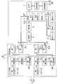
- FIG. 1 is a block diagram showing the configuration of a human detection system according to Embodiment 1 of the present invention.
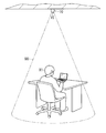
- FIG. 2 is a perspective view showing an example of use of the above human detection system.
- FIG. 3 is a waveform diagram of an output signal of the first light receiving unit in the above-described human detection system.
- FIG. 4A is a waveform diagram of output signals of the first light receiving unit and the second light receiving unit in the above-described human detection system.
- FIG. 4B is a waveform diagram of evaluation values in the above human detection system.
- FIG. 5 is an explanatory view conceptually showing the operation of the determination unit of the above human detection system.
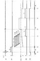
- FIG. 6 is a timing chart showing an operation example of the above human detection system.
- FIG. 1 is a block diagram showing the configuration of a human detection system according to Embodiment 1 of the present invention.
- FIG. 2 is a perspective view showing an example of use of the above human detection system.
- FIG. 3 is a waveform diagram of
- FIG. 7 is explanatory drawing which showed notionally operation
- FIG. 8 is an explanatory view conceptually showing the operation of the determination unit of the human detection system according to the second modified example of the first embodiment of the present invention.
- the following embodiments relate to a human detection system, and more particularly to a human detection system that detects the presence or absence of a person in the detection space based on the light reception intensity of infrared light from the detection space.
- the human detection system according to each embodiment described below is merely an example of the present invention, and the present invention is not limited to the following human detection system. Therefore, even if it is a range other than each following embodiment, if it is a range which does not deviate from the technical idea concerning this invention, various changes are possible according to a design etc.
- the person detection system 10 detects the presence or absence of the person 91 in a detection space 90 set in, for example, a living room of a house.
- the human detection system 10 detects the presence or absence of the human 91 based on the change in the light reception intensity of infrared light from the detection space 90. That is, the human detection system 10 detects the presence of the human 91 from the change in the light reception intensity of infrared light caused by the movement of the human 91 from outside the detection space 90 into the detection space 90 or the slight movement of the human 91 in the detection space 90
- “micromotion” means relatively small movement of the person 91, such as shaking of the body due to the breathing motion of the person 91, for example.
- the human detection system 10 detects whether the state of the detection space 90 is the presence state or the absence state.
- the “present state” is a state in which the person 91 exists in the detection space 90.
- the “absent state” is a state in which the person 91 does not exist in the detection space 90. Therefore, in the state in which the person 91 does not exist in the detection space 90, the detection result of the person detection system 10 is "absent".
- the detection result of the person detection system 10 changes from the "non-existent state" to the "presence state”. After that, while the person 91 is staying in the detection space 90, the detection result of the person detection system 10 maintains the "presence state".
- the detection result of the person detection system 10 changes from the "presence state” to the "absence state”.
- the detection result of the human detection system 10 is output to the illumination control system 80 (see FIG. 1).
- the lighting control system 80 includes a lighting fixture 81 (see FIG. 1) for lighting the detection space 90, and a control device 82 (see FIG. 1) for controlling the lighting fixture 81.
- the detection result of the human detection system 10 is input to the control device 82. If the detection result of the human detection system 10 indicates the "presence state”, the control device 82 turns on the lighting device 81. On the other hand, if the detection result of the human detection system 10 is “an absent state”, the control device 82 turns off the lighting fixture 81.
- the control device 82 may be a switch that is inserted in the power feeding path to the lighting fixture 81 and turns on / off the lighting of the lighting fixture 81.
- the human detection system 10 of this embodiment is used for the lighting control system 80 which automatically controls the lighting fixture 81 according to the presence or absence of the person 91. Accordingly, the human detection system 10 can automatically turn on the lighting fixture 81 when the human 91 enters the detection space 90. In addition, the human detection system 10 can suppress unnecessary power consumption due to forgetting to erase the lighting fixture 81 by automatically turning off the lighting fixture 81 when the person 91 leaves the detection space 90.
- the human detection system 10 includes a sensor main body 1 and a detection circuit 2.
- the sensor main body 1 has a first light receiving element 111 and a second light receiving element 112.
- first light receiving element 111 and the second light receiving element 112 are not particularly distinguished, each of the first light receiving element 111 and the second light receiving element 112 will be referred to as a “light receiving element 11”.
- the light receiving element 11 is a pyroelectric element, and outputs a signal (electric signal) according to a change in the light receiving intensity of infrared light from the detection space 90.
- the sensor main body 1 includes a first conversion circuit 121, a first amplification circuit 131, and a first A / D converter 141 as a circuit that performs signal processing of the electric signal output from the first light receiving element 111. Further, the sensor main body 1 includes a second conversion circuit 122, a second amplification circuit 132, and a second A / D converter 142 as a circuit that performs signal processing of an electric signal output from the second light receiving element 112. . The sensor body 1 outputs the outputs (electrical signals) of the first A / D converter 141 and the second A / D converter 142 to the detection circuit 2.
- the first conversion circuit 121 converts an electric signal output from the first light receiving element 111 from a current signal to a voltage signal.
- the first amplifier circuit 131 amplifies the voltage signal output from the first conversion circuit 121.
- the first A / D converter 141 converts an analog signal (voltage signal) output from the first amplifier circuit 131 into a digital signal.
- the second conversion circuit 122, the second amplification circuit 132, and the second A / D converter 142 have the same configuration as the first conversion circuit 121, the first amplification circuit 131, and the first A / D converter 141. Signal processing of the electrical signal output from the light receiving element 112 is performed.
- the sensor body 1 is used in combination with the optical system 15 (see FIG. 2).
- the optical system 15 is made of a lens or a mirror, or a combination of these, and condenses infrared light from the detection space 90 on the light receiving element 11.
- the sensor body 1 is housed in one case together with the detection circuit 2.
- the human detection system 10 including the sensor main body 1 is installed, for example, on a ceiling of a living room of a house, as shown in FIG. 2, and receives infrared light from a detection space 90 set in the living room.
- the detection circuit 2 includes a determination unit 4, a multiplication unit 5, an integration unit 6, an output unit 7, an integration timer 41, a standby timer 42, and a delay timer 43. Furthermore, the detection circuit 2 includes a first buffer 211 and a first filter unit 221 as a part that performs signal processing of an input signal (digital signal) from the first A / D converter 141. Further, the detection circuit 2 includes a second buffer 212 and a second filter unit 222 as a part that performs signal processing of an input signal (digital signal) from the second A / D converter 142.
- An input signal from the first A / D converter 141 is input to the first filter unit 221 via the first buffer 211.
- the first filter unit 221 attenuates or amplifies a specific frequency component.
- An input signal from the second A / D converter 142 is input to the second filter unit 222 via the second buffer 212.
- the second filter unit 222 attenuates or amplifies a specific frequency component.
- the detection circuit 2 mainly includes a computer such as a microcomputer.
- the detection circuit 2 realizes the functions of the above-described units by executing a program stored in a memory of a microcomputer by a processor of the microcomputer.
- the program may be pre-recorded in a memory, may be provided through a telecommunication line such as the Internet, or may be provided by being recorded in a recording medium such as a memory card.
- the output of the first light receiving element 111 is input to the multiplication unit 5 via the first conversion circuit 121, the first amplification circuit 131, the first A / D converter 141, the first buffer 211, and the first filter unit 221.
- the output of the second light receiving element 112 is input to the multiplication unit 5 through the second conversion circuit 122, the second amplification circuit 132, the second A / D converter 142, the second buffer 212, and the second filter unit 222.
- the first light receiving element 111 constitutes a first light receiving unit 31 together with the first conversion circuit 121, the first amplification circuit 131, the first A / D converter 141, the first buffer 211, and the first filter unit 221.
- the second light receiving element 112 constitutes a second light receiving unit 32 together with the second conversion circuit 122, the second amplification circuit 132, the second A / D converter 142, the second buffer 212, and the second filter unit 222.
- the first light receiving unit 31 constitutes the light receiving unit 3 together with the second light receiving unit 32.
- the light receiving unit 3 (the first light receiving unit 31 and the second light receiving unit 32) has the light receiving element 11, and multiplies the output signals V1 and V2 according to the change in the light receiving intensity of infrared light from the detection space 90 Output to 5
- the output signal V1 of the first light receiving unit 31 and the output signal V2 of the second light receiving unit 32 are separately input to the multiplying unit 5. Further, of the output signals V1 and V2 of the light receiving unit 3, the output signal V1 of the first light receiving unit 31 is also directly output to the determination unit 4.
- the output signals V1 and V2 of the first light receiving unit 31 and the second light receiving unit 32 are input to the determining unit 4 through the multiplying unit 5 and the integrating unit 6, and the output signal V1 of the first light receiving unit 31 is The signal is input without passing through the multiplication unit 5 and the integration unit 6.
- the first filter unit 221 extracts an AC component from the output of the first light receiving element 111.
- the second filter unit 222 extracts an AC component from the output of the second light receiving element 112.
- the frequency band through which each of the first filter unit 221 and the second filter unit 222 passes is set to, for example, 0.3 Hz to 1 Hz. This frequency band is a frequency band corresponding to the slight movement of the person 91.
- Low frequency components (including direct current components) of the outputs of the first filter unit 221 and the second filter unit 222, that is, the output signal V1 of the first light receiving unit 31 and the output signal V2 of the second light receiving unit 32 are removed. It becomes an alternating current signal.
- the frequency band (pass band) to be passed is different between the output signal V1 output directly to the determination unit 4 and the output signal V1 output to the multiplication unit 5 Is preferred.
- the pass band of the first filter unit 221 is, for example, 0.3 Hz to 1 Hz as described above.
- the pass band of the first filter unit 221 is, for example, a frequency band whose center frequency is around 1 Hz.
- the first filter unit 221 may have an individual filter for each output destination, or may switch the passband according to the operation mode of the determination unit 4 described later.
- the multiplication unit 5 multiplies the output signal V1 of the first light receiving unit 31 and the output signal V2 of the second light receiving unit 32.
- the multiplying unit 5 multiplies the instantaneous value of the output signal V1 of the first light receiving unit 31 by the instantaneous value of the output signal V2 of the second light receiving unit 32.
- the multiplying unit 5 multiplies the output signal V1 of the first light receiving unit 31 and the output signal V2 of the second light receiving unit 32 to obtain an output signal V1 of the first light receiving unit 31 and an output signal of the second light receiving unit 32.
- Synchronous detection is performed to extract an in-phase component with V2.
- the integration unit 6 integrates the multiplication result of the multiplication unit 5.
- the integration unit 6 has a memory for temporarily storing the multiplication result of the multiplication unit 5, and integrates the multiplication result of the multiplication unit 5 stored in the memory.
- the integration unit 6 obtains an integral value of the multiplication result of the latest integration time.
- the integration unit 6 obtains, as an evaluation value Vi1, a value obtained by integrating the multiplication results for a period for integration time (integral target period) having the current as an end point. That is, the integration unit 6 performs so-called movement integration.
- a multiplication result for the latest integration time is accumulated in the memory of the integration unit 6, and the multiplication result accumulated in the memory is updated by discarding the oldest data in order.
- the integration unit 6 integrates the multiplication result for the integration time stored in the memory to calculate an integral value (evaluation value Vi1) of the multiplication result for the latest integration time.
- the length of integration time is appropriately selected from, for example, 30 seconds, 60 seconds, and 90 seconds, depending on the application of the human detection system 10 and the like. As an example, the integration time is 30 seconds.
- the determination unit 4 determines the state of the detection space 90 based on the output signal of the light receiver 3 as the “presence state” in which the person 91 exists in the detection space 90 and the “absent state” in which the person 91 does not exist in the detection space 90 To determine which of the
- the operation mode of the determination unit 4 includes an approach detection mode and a stay detection mode.
- the entry detection mode is an operation mode for detecting the presence or absence of the entry of the person 91 into the detection space 90.
- the stay detection mode is an operation mode for detecting the presence or absence of the person 91 leaving the detection space 90.
- the determination unit 4 determines that the state is the presence state.
- the output signal V1 is the output signal V1 of the first light receiving unit 31 that is directly input to the determination unit 4.
- the first determination condition is that the amplitude of the output signal V1 is equal to or greater than the first threshold Vth1.
- the determination unit 4 determines that the comparison result of the amplitude of the output signal V1 and the first threshold value Vth1 satisfies the first determination condition, and determines that there is a presence state.
- determination unit 4 compares evaluation value Vi1 corresponding to the movement of person 91 in detection space 90 with a second threshold value Vth2 (see FIG. 4B), which is a value obtained from output signals V1 and V2. If the result satisfies the second judgment condition, it is judged as an absent state.
- the evaluation value Vi1 is an output value of the integration unit 6. That is, the evaluation value Vi1 is a value obtained by multiplying the output signal V1 of the first light receiving unit 31 and the output signal V2 of the second light receiving unit 32 by the multiplying unit 5 and integrating the multiplication result by the integrating unit 6 It is an integral value of the signals V1 and V2.
- the second determination condition is a state in which the evaluation value Vi1 is less than the second threshold Vth2 until a predetermined delay time elapses from the time when the evaluation value Vi1 becomes less than the second threshold Vth2. Is to continue. Specifically, the determination unit 4 compares the evaluation value Vi1 with the second threshold Vth2, and sets a temporary flag while the evaluation value Vi1 is less than the second threshold Vth2. Then, when the delay time elapses in a state where the temporary flag is set, the determination unit 4 determines that the second determination condition is satisfied, and determines that the user is absent. As a result, the determination unit 4 does not immediately determine that the evaluation value Vi1 is less than the second threshold value Vth2 as an absent state, but delays the determination of an absent state by a delay time, so-called an off delay function. To achieve.
- the output signals V1 and V2 of the first light receiving unit 31 and the second light receiving unit 32 correspond to the magnitude of the movement of the person 91 as shown in FIG. 4A, for example.
- In-phase detection component is included.
- the output signals V1 and V2 illustrated in FIG. 4A are both less than the first threshold Vth1.
- the first light receiving unit 31 and the second light receiving unit 32 are included in the output signal V1 of the first light receiving unit 31 and the output signal V2 of the second light receiving unit 32 in order to receive infrared rays from the same place.
- the detected components are correlated with one another. Therefore, in the multiplication result of the output signal V1 of the first light receiving unit 31 and the output signal V2 of the second light receiving unit 32, the detection component of the same phase is emphasized. Further, in the movement integral value of the multiplication result of the multiplication unit 5, noise components generated at random are reduced. Therefore, as shown in FIG. 4B, the evaluation value Vi1 consisting of the movement integral value of the multiplication result of the multiplication unit 5 increases from time t1 of integration to time t20 when the integration time passes, and is substantially constant after time t20. Become. In the example of FIG.
- the determination unit 4 since the evaluation value Vi1 is equal to or greater than the second threshold Vth2 at time t20, the determination unit 4 compares the evaluation value Vi1 with the second threshold Vth2 at time t20. It is judged that the judgment condition of is not satisfied.
- the operation mode of the determination unit 4 includes the standby mode in addition to the approach detection mode and the stay detection mode. That is, the determination unit 4 has at least three operation modes (entry detection mode, stay detection mode, and standby mode). The details of each operation mode will be described in the section “(2) Operation”.
- the determination unit 4 operates by alternatively selecting an operation mode from a plurality of operation modes including an approach detection mode, a stay detection mode, and a stay detection mode. Therefore, for example, the operation modes of both the approach detection mode and the stay detection mode are not simultaneously selected.
- the determination unit 4 switches the operation mode from the stay detection mode to the entry detection mode when determining that the user is not in the stay detection mode. In addition, when the determination unit 4 determines that the vehicle is in the presence state in the entry detection mode, the operation mode is switched from the entry detection mode to the standby mode. In addition, when a predetermined standby time has elapsed from when the operation in the standby mode is started, the determination unit 4 stays in the operation mode from the standby mode if the amplitude of the output signal V1 is less than the first threshold Vth1. Switch to detection mode. Furthermore, the determination unit 4 switches the operation mode from the stay detection mode to the standby mode when the amplitude of the output signal V1 becomes equal to or higher than the third threshold in the stay detection mode. In the present embodiment, it is assumed that the third threshold is the same value as the first threshold Vth1. However, the third threshold may be different from the first threshold Vth1.
- the determination unit 4 in the state where the person 91 does not exist in the detection space 90, the determination unit 4 basically operates in the entry detection mode, and detects the presence or absence of the entry of the person 91 into the detection space 90.
- the determination unit 4 in the state where the person 91 exists in the detection space 90, the determination unit 4 basically operates in the stay detection mode, and detects the presence or absence of the person 91 leaving the detection space 90.
- the integration timer 41 counts integration time.
- the integration timer 41 starts counting the integration time when the integration unit 6 starts the integration process.
- the count value of the integration timer 41 is reset when the determination unit 4 starts or ends the operation in the stay detection mode.
- the standby timer 42 counts the standby time.
- the standby timer 42 starts counting the standby time when the determination unit 4 starts the operation in the standby mode.
- the count value of the standby timer 42 is reset when the standby timer 42 finishes counting the standby time.
- the length of the waiting time is appropriately set, for example, in a range of several seconds to 10 seconds in accordance with the application of the human detection system 10 or the like. As an example, the waiting time is 10 seconds.
- the delay timer 43 counts delay time.
- the delay timer 43 starts counting of the delay time.
- the count value of the delay timer 43 is reset when the determination unit 4 starts or ends the operation in the stay detection mode.
- the length of the delay time is appropriately selected from, for example, 30 seconds, 60 seconds, and 90 seconds, depending on the application of the human detection system 10 and the like. As an example, the delay time is 30 seconds.
- the length of the delay time is preferably variable and can be arbitrarily changed by the user.
- the delay time is preferably longer than the waiting time.
- the multiplication unit 5 and the integration unit 6 are stopped. That is, the multiplication unit 5 and the integration unit 6 operate only while the operation mode of the determination unit 4 is in the stay detection mode. Therefore, the integration timer 41 interlocked with the integration unit 6 starts counting the integration time, triggered by the determination unit 4 starting operation in the stay detection mode. Furthermore, the determination unit 4 does not compare the evaluation value Vi1 with the second threshold Vth2 until the integration timer 41 has counted the integration time. When the integration timer 41 has counted the integration time, comparison of the evaluation value Vi1 with the second threshold Vth2 is started.
- the evaluation value Vi1 is compared with the second threshold Vth2 until the integration time elapses from the time when the integration unit 6 starts the integration process. Not performed. Therefore, while the operation mode is the entry detection mode or the standby mode, and until the integration timer 41 has finished counting the integration time even when the operation mode is the entry detection mode or the standby mode, the evaluation value Vi1 and the second The comparison with the threshold value Vth2 is not performed.
- the determination unit 4 performs the comparison between the amplitude of the output signal V1 and the first threshold Vth1 as needed regardless of the operation mode. Therefore, the determination unit 4 can compare the amplitude of the output signal V1 with the first threshold Vth1 (third threshold) even in the stay detection mode, and the amplitude of the output signal V1 is the first threshold Vth1.
- the operation mode is switched from the stay detection mode to the standby mode.
- the output unit 7 outputs the determination result of the determination unit 4 to the illumination control system 80 as the detection result of the human detection system 10.
- the output unit 7 serially outputs a determination signal representing the determination result of the determination unit 4 to the human detection system 10.
- the output unit 7 outputs a determination signal including the start bit, the determination result, and the stop bit.
- the determination signal may include, for example, mode information indicating the operation mode of the determination unit 4 and information such as the waveforms of the output signals V1 and V2, in addition to the determination result of “present state” or “absent state”. .
- FIG. 5 is an explanatory view conceptually showing the operation of the determination unit 4.
- a first circle C1 represents the determination result of the determination unit 4 that is “absent state”.
- the second circle C2 represents the determination result of the determination unit 4 as the “presence state”.
- the broken line arrow indicates the flow of processing of the determination unit 4 based on the comparison result of the amplitude of the output signal V1 and the first threshold value Vth1.
- the solid-line arrow represents the flow of processing of the determination unit 4 based on the comparison result of the evaluation value Vi1 and the second threshold value Vth2.
- step S1 entity detection mode
- step S1 the determination unit 4 compares the amplitude of the output signal V1 with the first threshold value Vth1. At this time, if the amplitude of the output signal V1 is less than the first threshold Vth1, the determination unit 4 continues the operation in the entry detection mode (step S2). On the other hand, when the amplitude of the output signal V1 is equal to or greater than the first threshold Vth1, the determination unit 4 switches the operation mode from the entry detection mode to the standby mode (step S3). At this time, since the determination result of the determination unit 4 is in the existing state, step S4 (standby mode) is within the second circle C2.
- step S4 the determination unit 4 compares the amplitude of the output signal V1 with the first threshold Vth1 when the standby timer 42 has counted the standby time. If the amplitude of the output signal V1 is less than the first threshold Vth1 when the standby timer 42 has counted the standby time, the determination unit 4 resets the count value of the standby timer 42, and the operation mode is the standby mode.
- step S5 the stay detection mode
- the determination unit 4 resets the count value of the standby timer 42 in standby mode. The operation of is continued (step S7).
- the determination unit 4 starts comparison of the evaluation value Vi1 with the second threshold Vth2 as needed from the time when the integration timer 41 has finished counting the integration time. Then, when the evaluation value Vi1 becomes equal to or more than the second threshold value Vth2, the determination unit 4 continues the operation in the stay detection mode without resetting the count value of the integration timer 41 (step S9). Further, the determination unit 4 also compares the amplitude of the output signal V1 with the first threshold Vth1 in the stay detection mode, and operates the operation mode if the amplitude of the output signal V1 becomes equal to or greater than the first threshold Vth1. The stay detection mode is switched to the standby mode (step S10). At this time, the determination unit 4 resets the count value of the integration timer 41.
- step S6 when the evaluation value Vi1 becomes smaller than the second threshold value Vth2, the delay timer 43 starts counting of the delay time.
- the determination unit 4 continues the operation in the stay detection mode until the delay timer 43 finishes counting the delay time. If the evaluation value Vi1 is less than the second threshold Vth2 when the delay timer 43 finishes counting the delay time, the determination unit 4 switches the operation mode from the stay detection mode to the entry detection mode (step S8). At this time, since the determination result of the determination unit 4 is an absent state, step S1 (entry detection mode) is within the first circle C1. At this time, the determination unit 4 resets the count value of the integration timer 41 and the count value of the delay timer 43.
- the determination unit 4 continues the operation in the stay detection mode (step S9). At this time, the determination unit 4 resets the count value of the integration timer 41 and the count value of the delay timer 43. If the amplitude of the output signal V1 becomes equal to or greater than the first threshold Vth1 while the delay timer 43 is counting the delay time, the determination unit 4 switches the operation mode from the stay detection mode to the standby mode (step S10). At this time, the determination unit 4 resets the count value of the integration timer 41 and the count value of the delay timer 43.
- the determination unit 4 determines that the state is the presence state. Then, when the determination unit 4 determines the presence state in the entry detection mode, the determination unit 4 switches the operation mode from the entry detection mode to the standby mode. In addition, if the amplitude of the output signal V1 is less than the first threshold Vth1 when the standby time has elapsed since the start of the operation in the standby mode, the determination unit 4 changes the operation mode from the standby mode to the stay detection mode. Switch.
- the determination unit 4 determines that the evaluation value Vi1 is less than the second threshold Vth2 until a predetermined delay time elapses from the time when the evaluation value Vi1 becomes less than the second threshold Vth2. If it continues, it will be judged as an absent state. Then, when the determination unit 4 determines that the user is not in the stay detection mode, the determination unit 4 switches the operation mode from the stay detection mode to the entry detection mode.
- Table 1 shows the operation of the determination unit 4 described above.
- the determination unit 4 performs the process of step S2 or step S3 according to the comparison result of the amplitude of the output signal V1 and the first threshold value Vth1. While the operation mode of the determination unit 4 is the entry detection mode, the determination result of the determination unit 4 is an absent state.
- the determination target of the determination unit 4 is the amplitude of the output signal V1. Then, the determination unit 4 performs the process of step S5 or step S7 in accordance with the comparison result of the amplitude of the output signal V1 and the first threshold value Vth1. While the operation mode of the determination unit 4 is the standby mode, the determination result of the determination unit 4 is in the existing state.
- the determination target of the determination unit 4 is both the amplitude of the output signal V1 and the evaluation value Vi1. Then, the determination unit 4 performs the process of step S10 according to the comparison result of the amplitude of the output signal V1 and the first threshold value Vth1. The determination unit 4 performs the process of step S8 or S9 in accordance with the comparison result of the evaluation value Vi1 and the second threshold value Vth2. While the operation mode of the determination unit 4 is the stay mode, the determination result of the determination unit 4 is an existing state.
- the processing of the determination unit 4 has priority, and the determination unit 4 preferentially executes processing with high priority.
- the determination unit 4 determines both the amplitude of the output signal V1 and the evaluation value Vi1, but the processing according to the amplitude of the output signal V1 than the processing according to the evaluation value Vi1.
- the priority is higher. That is, while the determination unit 4 is operating in the stay detection mode, when the amplitude of the output signal V1 becomes equal to or more than the first threshold Vth1 and the evaluation value Vi1 becomes equal to or more than the second threshold Vth2, the determination unit 4 performs step The process of step S10 is executed instead of the process of S9.
- FIG. 6 shows the output signal V1, the first flag F1, the evaluation value Vi1, the second flag F2, and the third flag F3 in order from the top, with the horizontal axis as a time axis.
- the first flag F1 becomes “H” (High) while the standby timer 42 is counting the standby time T1, and becomes “L” (Low) if the standby timer 42 has not counted the standby time T1.
- the second flag F2 is a temporary flag that represents the comparison result of the evaluation value Vi1 in the determination unit 4 and the second threshold value Vth2.
- the second flag F2 is "H” (High) if the evaluation value Vi1 is less than the second threshold Vth2, and is “L” (Low) if the evaluation value Vi1 is greater than or equal to the second threshold Vth2.
- the third flag F3 represents the determination result of the determination unit 4.
- the third flag F3 is "H” (High) while the determination unit 4 determines that the present state is present, and is "L" (Low) while the determination unit 4 determines that the present state is absent.
- "M1" represents a period in which the operation mode of the determination unit 4 is an entry detection mode
- M3 represents a period in which the operation mode of the determination unit 4 is in a standby mode
- “M2" represents a determination. It represents a period during which the operation mode of the unit 4 is the stay detection mode.
- “Ti1”, “Ti2”, “Ti3”,... Indicate integration target periods, that is, periods in which the integration unit 6 is to be subjected to movement integration.
- the determination unit 4 operates in the entry detection mode for the period before time t1, the determination result of the determination unit 4 is absent, and the third flag F3 is "L". .
- the amplitude of the output signal V1 becomes equal to or greater than the first threshold value Vth1. Therefore, the determination unit 4 determines that the state is the presence state, and the third flag F3 becomes “H”.
- the operation mode of the determination unit 4 is switched from the entry detection mode to the standby mode.
- the first flag F1 is "H".
- the amplitude of the output signal V1 is less than the first threshold Vth1, so the operation mode of the determination unit 4 switches from the standby mode to the stay detection mode.
- the first flag F1 becomes "L”.
- the determination unit 4 starts to compare the evaluation value Vi1 with the second threshold Vth2 as needed from time t3 when the integration timer 41 has finished counting the integration time.
- the integration unit 6 performs integration for the integration target period Ti1, and the determination unit 4 compares the evaluation value Vi1 obtained as a result thereof with the second threshold value Vth2.
- the second flag F2 becomes “H”, and the delay timer 43 starts counting the delay time T2.
- the output signal V1 fluctuates and the evaluation value Vi1 becomes equal to or greater than the second threshold Vth2, so that the second flag F2 is “L "become.
- the evaluation value Vi1 becomes smaller than the second threshold Vth2 at time t5 when the integration time has elapsed. Therefore, at time t5, the second flag F2 becomes "H", and the delay timer 43 starts counting the delay time T2. Thereafter, if there is no large change in the output signal V1, at time t6 when the delay timer 43 finishes counting the delay time T2, the determination unit 4 determines that there is an absent state, and the third flag F3 becomes "L". At this time, the operation mode of the determination unit 4 is switched from the stay detection mode to the entry detection mode.
- the human detection system 10 includes the light receiving unit 3 and the determination unit 4.
- the light receiving unit 3 has a light receiving element 11 that outputs a signal corresponding to the change in the light receiving intensity of infrared light from the detection space 90.
- the determination unit 4 determines that the state of the detection space 90 is an existence state in which a person 91 exists in the detection space 90 and an absence state in which a person does not exist in the detection space 90. Determine which one.
- the operation mode of determination unit 4 includes an entry detection mode for detecting presence or absence of person 91 entering detection space 90 and a stay detection mode for detecting presence or absence of person 91 from detection space 90.
- the determination unit 4 determines the presence state if the comparison result of the amplitude of the output signal V1 and the first threshold value Vth1 satisfies the first determination condition.
- determination unit 4 has a second comparison result between evaluation value Vi1 corresponding to the movement of person 91 in detection space 90 and second threshold value Vth2, which is a value obtained from output signals V1 and V2. When the determination condition is satisfied, it is configured to determine that the user is absent.
- the operation mode of the determination unit 4 is an entry detection mode for detecting presence or absence of the person 91 entering the detection space 90 and a stay detection mode for detecting presence or absence of the person 91 leaving the detection space 90 And contains. That is, in the entry detection mode, the determination unit 4 determines whether the state of the detection space 90 is in the presence state, and in the stay detection mode, determines whether the state of the detection space 90 is in the absence state. . Thus, the determination unit 4 detects the change from the absent state to the present state and the change from the present state to the absent state in different operation modes.
- the determination unit 4 is in the stay detection mode and has higher sensitivity than the entry detection mode, detection leaks of human's fine movement (such as turning around) are less likely to occur in the stay detection mode, and false detection in the entry detection mode It is possible to suppress the occurrence.
- the determination unit 4 determines whether or not it is in the presence state based on the comparison result of the amplitude of the output signal V1 and the first threshold value Vth1.
- determination unit 4 is a value obtained from output signals V1 and V2 in the stay detection mode, and is based on the comparison result of evaluation value Vi1 according to the movement of person 91 in detection space 90 and second threshold value Vth2.
- the algorithm of the determination process of the determination unit 4 is different between the entry detection mode and the stay detection mode. Therefore, for example, in the stay detection mode, the application of the algorithm suitable for detecting the slight movement of the person 91 makes it more difficult for the detection failure of the slight movement of the person 91 to occur.
- the operation mode of the determination unit 4 is in the entry detection mode, the multiplication unit 5 and the integration unit 6 are not operating. Therefore, the power consumption in the detection circuit 2 can be suppressed lower in the approach detection mode than in the stay detection mode.
- the evaluation value Vi1 be an integral value of the output signal.
- the evaluation value Vi1 is an integral value of the product of the output signals V1 and V2. According to this configuration, in the stay detection mode, the determination unit 4 determines whether or not the person 91 is present based on the integral value rather than the instantaneous values of the output signals V1 and V2. Therefore, for example, even when the person 91 is slightly moved by breathing, the slight movement (fine movement) is periodically repeated, so that the determination unit 4 easily determines that the person 91 is present.
- the evaluation value Vi1 is an integral value of the output signal
- the evaluation value Vi1 is a value obtained from the output signals V1 and V2
- the movement of the person 91 in the detection space 90 It may be a value according to
- the first determination condition is that the amplitude of the output signal V1 be equal to or greater than the first threshold Vth1.
- the determination unit 4 determines the presence state as soon as the amplitude of the output signal V1 reaches the first threshold value Vth1. Therefore, for example, when the person 91 enters the detection space 90, the lighting fixture 81 can be turned on immediately.
- the determination unit 4 be configured to switch the operation mode from the stay detection mode to the entry detection mode when it determines that the user is in the absent state in the stay detection mode.
- the operation mode of the determination unit 4 detects the presence or absence of the entry of the person 91 from the detection space 90 when the person 91 moves from the inside of the detection space 90 to the outside of the detection space 90 It will switch to detection mode.
- the configuration in which the determination unit 4 automatically switches the operation mode from the stay detection mode to the entry detection mode is not an essential configuration for the human detection system 10 and can be omitted as appropriate.
- the operation mode of the determination unit 4 preferably further includes a standby mode.
- the determination unit 4 switch the operation mode from the entry detection mode to the standby mode when it determines that the presence state is in the entry detection mode.
- the amplitude of the output signal V1 is less than the first threshold Vth1 when the predetermined standby time T1 has elapsed since the start of the operation in the standby mode, the determination unit 4 stays in the operation mode from the standby mode.
- it is configured to switch to the detection mode.
- the operation mode of the determination unit 4 when there is a movement of the person 91 from outside the detection space 90 into the detection space 90, the operation mode of the determination unit 4 is a stay for detecting the presence or absence of the person 91 leaving the detection space 90 It will be switched to detection mode automatically. Moreover, since the operation mode of the determination unit 4 is switched from the entry detection mode to the stay detection mode after passing through the standby mode, the stay detection mode is not shifted immediately after the person 91 has a large movement. The multiplication unit 5 and the integration unit 6 stop their operation while the operation mode of the determination unit 4 is in the standby mode. Therefore, the power consumption in the detection circuit 2 can be suppressed to be lower in the standby mode than in the stay detection mode.
- the configuration in which the determination unit 4 automatically switches the operation mode from the entry detection mode to the stay detection mode via the standby mode is not an essential configuration for the human detection system 10 and can be omitted as appropriate.
- the determination unit 4 detects the stay in the operation mode when the amplitude of the output signal V1 in the stay detection mode becomes equal to or higher than the third threshold (the first threshold Vth1 in the present embodiment). Preferably, it is configured to switch from the mode to the standby mode. According to this configuration, for example, when a large movement (such as walking) of the person 91 occurs while the determination unit 4 is operating in the stay detection mode, the operation mode of the determination unit 4 is automatically switched to the standby mode. Therefore, for example, in either case where the person 91 only passes through the detection space 90 or in the case where the person 91 leaves the detection space 90 after staying in the detection space 90, the determination unit 4 determines that the person 91 has left. Start operation from standby mode. Therefore, after the person 91 leaves from the detection space 90, the variation in the time required for the determination unit 4 to determine that the user is absent can be reduced.
- the third threshold the first threshold Vth1 in the present embodiment
- the evaluation value Vi1 is the second threshold Vth2 until the predetermined delay time T2 elapses from the time when the evaluation value Vi1 becomes less than the second threshold Vth2. It is preferred that the less-than condition be to continue. According to this configuration, in the stay detection mode, the determination unit 4 does not perform the determination of the absent state immediately after the evaluation value Vi1 becomes less than the second threshold value Vth2. Therefore, for example, in the state where the person 91 is present in the detection space 90, it is difficult for the lighting fixture 81 to be turned off.
- FIG. 7 is an explanatory view conceptually showing the operation of the determination unit 4 of the human detection system 10 according to the first modification of the first embodiment.
- FIG. 7 is a conceptual view similar to FIG. 5, so the detailed description will be omitted.
- the human detection system 10 according to the first modification differs from the human detection system 10 according to the first embodiment in that the determination unit 4 does not have a function of switching the operation mode from the stay detection mode to the standby mode.
- the operation mode of determination unit 4 is then switched directly to the standby mode There is nothing to do. That is, the operation of the determination unit 4 in the stay detection mode is either to continue the operation in the stay detection mode (step S9) or to shift to the entry detection mode (step S1) (step S8).
- the operation mode of the determination unit 4 is the stay detection mode, the comparison between the amplitude of the output signal V1 and the first threshold Vth1 is unnecessary.
- FIG. 8 is an explanatory view conceptually showing the operation of the determination unit 4 of the human detection system 10 according to the second modified example of the first embodiment.
- FIG. 8 is a conceptual view similar to FIG. 5, so the detailed description will be omitted.
- the human detection system 10 according to the second modification is different from the human detection system 10 according to the first embodiment in that the operation mode of the determination unit 4 does not include the standby mode.
- the determination unit 4 is configured to switch the operation mode from the entry detection mode to the stay detection mode when it determines that the presence state is in the entry detection mode. That is, the operation mode of the determination unit 4 is directly switched from the entry detection mode (step S1) to the stay detection mode (step S6) (step S3).
- the second modification when the operation mode of the determination unit 4 is in the stay detection mode, the comparison between the amplitude of the output signal V1 and the first threshold Vth1 is unnecessary.
- the human detection system 10 may be used not only for homes but also for non-homes such as offices, stores, or factories. Furthermore, the human detection system 10 may be used outdoors as well as indoors.
- the detection result of the human detection system 10 is not limited to the control of the lighting device, and may be used to control an electrical device other than the lighting device, such as a ventilation fan or a security camera. Furthermore, the detection result of the human detection system 10 is not limited to the control of the electric device, and may be used, for example, to monitor the position of the human 91.
- the first determination condition that is, the condition for determining the presence state in the entry detection mode by the determination unit 4 is not limited to the amplitude of the output signal V1 being equal to or more than the first threshold Vth1.
- the first determination condition may be that the number of times the amplitude of the output signal V1 exceeds the first threshold Vth1 in a predetermined period reaches a specified number, or the like.
- the determination unit 4 compares the amplitude of at least one of the output signal V1 of the first light receiving unit 31 and the output signal V2 of the second light receiving unit 32 with the first threshold value Vth1. Based on the determination, it may be determined whether or not it exists.
- the determination unit 4 determines You may judge.
- the determining unit 4 may determine whether the current state is the presence state.
- the second determination condition that is, the condition for determining that the determination unit 4 is in the absent state in the stay detection mode is evaluated until the delay time elapses from the time when the evaluation value Vi1 becomes smaller than the second threshold Vth2.
- the state in which the value Vi1 is less than the second threshold value Vth2 is not limited to being continued.
- the second determination condition may be that the evaluation value Vi1 is less than the second threshold Vth2. That is, the off delay function is not a function essential to the determination unit 4, and the determination unit 4 may determine that the user is absent when the evaluation value Vi1 becomes less than the second threshold Vth2 in the stay detection mode.
- this configuration is the same as the configuration in which the delay time is set to zero in the configuration of the first embodiment.
- the operation mode of the determination unit 4 may include a delay mode as an operation mode for realizing the off-delay function in the determination unit 4.
- the determination unit 4 does not immediately determine the absence state even if the comparison result of the evaluation value Vi1 and the second threshold value Vth2 in the stay detection mode satisfies the second determination condition. That is, the determination unit 4 sets a temporary absence flag, switches the operation mode from the stay detection mode to the delay mode, and starts counting of the delay time.
- the operation of the determination unit 4 in the delay mode is the same as the operation of the determination unit 4 counting the delay time in the human detection system 10 according to the first embodiment.
- the off-delay function may be realized not by the determination unit 4 but by the subsequent stage of the determination unit 4, for example, the output unit 7.
- the determination unit 4 immediately determines that the user is not in the present state.
- the output unit 7 receives the determination result of the absent state determination unit 4, the output unit 7 starts counting of the delay time.
- the detection spaces 90 for receiving infrared light by the first light receiving unit 31 and the second light receiving unit 32 may not be completely coincident with each other, and may be shifted from each other. In this case, a phase difference may occur between the detection component included in the output signal V1 of the first light receiving unit 31 and the detection component included in the output signal V2 of the second light receiving unit 32.
- the multiplication result of the multiplication unit 5 is not always a positive value, but may be a negative value. Therefore, in addition to the second threshold value Vth2, a negative threshold value may be set as a comparison target of the evaluation value Vi1. In this case, the determination unit 4 may determine whether or not the person 91 exists based on the comparison result of the evaluation value Vi1 and the negative threshold value.
- the human detection system 10 according to the present embodiment is different from the human detection system 10 according to the first embodiment in that the light receiving unit 3 includes only the first light receiving unit 31.
- the same components as in the first embodiment are denoted by the same reference numerals, and the description thereof will be appropriately omitted.
- the determination unit 4 compares the amplitude of the output signal V1 of the first light receiving unit 31 with the first threshold value Vth1. It is determined whether or not exists.
- the determination unit 4 uses the integral value of the multiplication result of the output signal V1 of the first light receiving unit 31 and the reference signal as the evaluation value Vi1. That is, the evaluation value Vi1 is a value obtained by multiplying the output signal V1 of the first light receiving unit 31 and the reference signal by the multiplying unit 5 and integrating the multiplication result by the integrating unit 6.
- the reference signal here is, for example, a sine wave of a frequency (for example, 0.3 Hz and 0.5 Hz) corresponding to the fine movement of the person 91. Further, the reference signal may be, for example, a signal having substantially the same phase as the output signal V1 of the first light receiving unit 31 by shifting the output signal V1 of the first light receiving unit 31 by a predetermined time.
- the determination unit 4 operates in two operation modes, the entrance detection mode and the stay detection mode. It is possible.
- the configuration of the human detection system 10 according to the second embodiment can be appropriately combined with the configuration of the first embodiment (including the modification).
Landscapes
- Physics & Mathematics (AREA)
- General Physics & Mathematics (AREA)
- Spectroscopy & Molecular Physics (AREA)
- Life Sciences & Earth Sciences (AREA)
- General Life Sciences & Earth Sciences (AREA)
- Geophysics (AREA)
- Geophysics And Detection Of Objects (AREA)
- Photometry And Measurement Of Optical Pulse Characteristics (AREA)
Priority Applications (1)
| Application Number | Priority Date | Filing Date | Title |
|---|---|---|---|
| TR2018/10941A TR201810941T1 (tr) | 2016-02-23 | 2017-02-10 | İnsan algılama sistemi. |
Applications Claiming Priority (2)
| Application Number | Priority Date | Filing Date | Title |
|---|---|---|---|
| JP2016-032504 | 2016-02-23 | ||
| JP2016032504A JP6920645B2 (ja) | 2016-02-23 | 2016-02-23 | 人検知システム |
Publications (1)
| Publication Number | Publication Date |
|---|---|
| WO2017145791A1 true WO2017145791A1 (ja) | 2017-08-31 |
Family
ID=59686580
Family Applications (1)
| Application Number | Title | Priority Date | Filing Date |
|---|---|---|---|
| PCT/JP2017/004852 Ceased WO2017145791A1 (ja) | 2016-02-23 | 2017-02-10 | 人検知システム |
Country Status (4)
| Country | Link |
|---|---|
| JP (1) | JP6920645B2 (https=) |
| TR (1) | TR201810941T1 (https=) |
| TW (1) | TWI658437B (https=) |
| WO (1) | WO2017145791A1 (https=) |
Families Citing this family (3)
| Publication number | Priority date | Publication date | Assignee | Title |
|---|---|---|---|---|
| JP2020051756A (ja) * | 2018-09-21 | 2020-04-02 | パナソニックIpマネジメント株式会社 | 人検知システム及びプログラム |
| JP7253728B2 (ja) * | 2018-09-21 | 2023-04-07 | パナソニックIpマネジメント株式会社 | 人検知システム及びプログラム |
| EP4466688A2 (en) * | 2022-01-17 | 2024-11-27 | Simplisafe, Inc. | Motion detection |
Citations (5)
| Publication number | Priority date | Publication date | Assignee | Title |
|---|---|---|---|---|
| JPH063366A (ja) * | 1992-06-23 | 1994-01-11 | Matsushita Electric Works Ltd | 赤外線式人体検知器 |
| JPH0896967A (ja) * | 1994-09-26 | 1996-04-12 | Matsushita Electric Works Ltd | 赤外線式人体検知装置 |
| JP2008224528A (ja) * | 2007-03-14 | 2008-09-25 | Yamagata Chinoo:Kk | 人体検知装置 |
| JP2010256045A (ja) * | 2009-04-21 | 2010-11-11 | Taisei Corp | 広域・高精度人体検知センサ |
| JP2014202614A (ja) * | 2013-04-05 | 2014-10-27 | オムロン株式会社 | 赤外線検知装置および検知対象の検知方法 |
Family Cites Families (6)
| Publication number | Priority date | Publication date | Assignee | Title |
|---|---|---|---|---|
| JP3012751B2 (ja) * | 1992-03-13 | 2000-02-28 | 松下電器産業株式会社 | 在席検出装置及び安全制御装置 |
| TWM394544U (en) * | 2010-08-19 | 2010-12-11 | Tpv Electronics Fujian Co Ltd | Display with auto off function by person infrared sensor |
| CN103197354B (zh) * | 2013-03-22 | 2015-08-12 | 黄程云 | 数字式被动红外静止人体探测器及其探测方法 |
| CN103234641B (zh) * | 2013-04-02 | 2015-04-22 | 浙江大学 | 检测动静态人体的被动式热释电红外探测器及低误报方法 |
| TWM467256U (zh) * | 2013-05-21 | 2013-12-01 | zhen-rong Lin | 人體感應開關 |
| JP6011568B2 (ja) * | 2014-03-13 | 2016-10-19 | 三菱電機ビルテクノサービス株式会社 | 乗客コンベアの人検知装置 |
-
2016
- 2016-02-23 JP JP2016032504A patent/JP6920645B2/ja not_active Expired - Fee Related
-
2017
- 2017-02-10 TR TR2018/10941A patent/TR201810941T1/tr unknown
- 2017-02-10 WO PCT/JP2017/004852 patent/WO2017145791A1/ja not_active Ceased
- 2017-02-15 TW TW106104847A patent/TWI658437B/zh active
Patent Citations (5)
| Publication number | Priority date | Publication date | Assignee | Title |
|---|---|---|---|---|
| JPH063366A (ja) * | 1992-06-23 | 1994-01-11 | Matsushita Electric Works Ltd | 赤外線式人体検知器 |
| JPH0896967A (ja) * | 1994-09-26 | 1996-04-12 | Matsushita Electric Works Ltd | 赤外線式人体検知装置 |
| JP2008224528A (ja) * | 2007-03-14 | 2008-09-25 | Yamagata Chinoo:Kk | 人体検知装置 |
| JP2010256045A (ja) * | 2009-04-21 | 2010-11-11 | Taisei Corp | 広域・高精度人体検知センサ |
| JP2014202614A (ja) * | 2013-04-05 | 2014-10-27 | オムロン株式会社 | 赤外線検知装置および検知対象の検知方法 |
Also Published As
| Publication number | Publication date |
|---|---|
| JP6920645B2 (ja) | 2021-08-18 |
| TWI658437B (zh) | 2019-05-01 |
| TW201734967A (zh) | 2017-10-01 |
| JP2017150910A (ja) | 2017-08-31 |
| TR201810941T1 (tr) | 2018-08-27 |
Similar Documents
| Publication | Publication Date | Title |
|---|---|---|
| TWI727415B (zh) | 人檢測系統及程式 | |
| TWI720608B (zh) | 人檢測系統及電腦程式產品 | |
| CN102177534B (zh) | 具有选择性发射的占用感测 | |
| WO2017145791A1 (ja) | 人検知システム | |
| JP2010206714A (ja) | 機器制御システム | |
| JP6667158B2 (ja) | 赤外線検出システム | |
| JP2014202614A (ja) | 赤外線検知装置および検知対象の検知方法 | |
| JP6380892B2 (ja) | 赤外線検知装置及び検知方法 | |
| WO2019098070A1 (ja) | センサシステム、照明制御システム、プログラム | |
| JPWO2016038893A1 (ja) | 機器管理装置、及び、機器管理方法 | |
| JP3248123B2 (ja) | 赤外線式移動体検知装置 | |
| JP2017150910A5 (https=) | ||
| JP6917575B2 (ja) | 人検知システム、プログラム及び人検知方法 | |
| JP4134125B2 (ja) | 2線式人体検知センサー付き自動スイッチ | |
| JP2011208480A (ja) | 自動ドア用物体検出装置 | |
| WO2011151754A1 (en) | A method and system for controlling the status of a device | |
| JP2009244158A (ja) | 人感検知器 | |
| KR100731973B1 (ko) | 자동전력 제어장치 | |
| JP2001237085A (ja) | 人体検出機能付配線器具 | |
| US20190098732A1 (en) | Motion-sensing match method | |
| KR102521484B1 (ko) | 미세먼지 농도 측정 장치의 사용자 가이드 정보 제공 방법 | |
| JP2017058331A (ja) | 検知回路、及びそれを備えた赤外線検出装置 | |
| JPH0681145U (ja) | 光電スイッチ | |
| RU27873U1 (ru) | Пожарный извещатель | |
| JP3169811U (ja) | 方向判別センサー |
Legal Events
| Date | Code | Title | Description |
|---|---|---|---|
| NENP | Non-entry into the national phase |
Ref country code: DE |
|
| 121 | Ep: the epo has been informed by wipo that ep was designated in this application |
Ref document number: 17756232 Country of ref document: EP Kind code of ref document: A1 |
|
| 122 | Ep: pct application non-entry in european phase |
Ref document number: 17756232 Country of ref document: EP Kind code of ref document: A1 |