WO2017145437A1 - 炊飯器 - Google Patents
炊飯器 Download PDFInfo
- Publication number
- WO2017145437A1 WO2017145437A1 PCT/JP2016/080841 JP2016080841W WO2017145437A1 WO 2017145437 A1 WO2017145437 A1 WO 2017145437A1 JP 2016080841 W JP2016080841 W JP 2016080841W WO 2017145437 A1 WO2017145437 A1 WO 2017145437A1
- Authority
- WO
- WIPO (PCT)
- Prior art keywords
- inner lid
- lid
- locking piece
- attached
- rice cooker
- Prior art date
- Legal status (The legal status is an assumption and is not a legal conclusion. Google has not performed a legal analysis and makes no representation as to the accuracy of the status listed.)
- Ceased
Links
Images








Classifications
-
- A—HUMAN NECESSITIES
- A47—FURNITURE; DOMESTIC ARTICLES OR APPLIANCES; COFFEE MILLS; SPICE MILLS; SUCTION CLEANERS IN GENERAL
- A47J—KITCHEN EQUIPMENT; COFFEE MILLS; SPICE MILLS; APPARATUS FOR MAKING BEVERAGES
- A47J27/00—Cooking-vessels
Definitions
- the present invention relates to a rice cooker that prevents forgetting to attach a liquid tray.
- a conventional rice cooker is provided with a main body in which the inner pot is detachably disposed, and a lid body covering the inner pot is provided on the main body so as to be freely opened and closed.
- a first inner lid that closes the upper end opening of the inner hook is detachably provided on the lid.
- a receiving tray (second inner lid) that separates and returns the liquid neva is further provided on the lower surface of the first inner lid on the inner hook side.
- the second inner lid also serves as a filter that prevents clogging of the inlet of the exhaust passage provided in the first inner lid, that is, the exhaust hole.
- the rice cooking process may be executed in a state where the second inner lid is forgotten to be attached to the first inner lid due to misuse by the user. In this case, the generated neva cannot be separated, and there is a problem that spillage occurs.
- Patent Document 1 moves to an interference position that interferes with the inner hook or the main body with the second inner lid removed from the first inner lid, that is, a contact position, and the inner lid with the second inner lid attached.
- An interference member that moves to a non-interference position that does not interfere with the shuttle or the main body, that is, a position that does not contact, is provided.
- the interference member moves from the non-interference position to the interference position. Therefore, when the lid is closed in this state, the interference member interferes with the inner hook or the main body.
- Patent Document 1 needs to provide a mechanism for preventing forgetting to attach the second inner lid separately from the mechanism for attaching the second inner lid to the first inner lid. there were.
- This invention was made in order to solve the above subjects, and it aims at providing the rice cooker which can prevent forgetting attachment of a lower cover, suppressing cost.
- a rice cooker according to the present invention comprises a main body that houses an inner pot, a lid that is provided on the main body so as to be freely opened and closed, and an inner lid that is attached to the lower surface of the lid and has a neva storage space.
- the inner lid includes a first inner lid attached to the lower surface of the lid body, and a second inner lid attached to the lower surface of the first inner lid, and the first inner lid is A first locking piece for locking the second inner lid, wherein the first locking piece is in the state where the second inner lid is not attached to the first inner lid; When the second inner lid is attached to the first inner lid, the second inner lid is in a position where it does not interfere with the lid.
- the second inner lid is locked by the first locking piece provided in the first inner lid, and the second inner lid is attached to the first inner lid. it can. Further, when the first inner lid is attached to the lid in a state where the second inner lid is not attached to the first inner lid, the first locking piece and the lid of the first inner lid Interfere with each other and the first inner lid cannot be attached to the lid. Therefore, forgetting to attach the second inner lid can be prevented.
- the first locking piece allows the second inner lid to be attached to the first inner lid and prevents forgetting to attach the second inner lid. It is not necessary to separately provide a mechanism for attaching to one inner lid and a mechanism for preventing forgetting to attach the second inner lid, and forgetting to attach the second inner lid can be prevented while reducing costs.
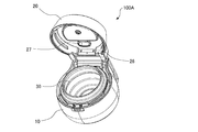
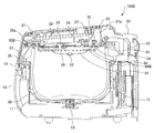
- FIG. 1 is an external perspective view of a rice cooker 100A according to Embodiment 1 of the present invention
- FIG. 2 is an external perspective view of the rice cooker 100A according to Embodiment 1 of the present invention with the inner lid 40A removed.
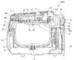
- 3 is a schematic longitudinal sectional view of rice cooker 100A according to Embodiment 1 of the present invention
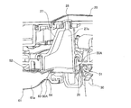
- FIG. 4 is a longitudinal section around the steam path of rice cooker 100A according to Embodiment 1 of the present invention.
- FIG. 1 to FIG. 3 the rice cooker 100A according to the first embodiment has a bottomed cylindrical inner pot 30 that holds a heated object such as rice and the like therein so that it can be taken out freely.
- An inner lid 40A is detachably attached to the surface on the side of 30, that is, the lower surface, and closes the upper opening of the inner hook 30 when the upper surface of the main body 10 is closed with the lid body 20.
- the inner hook 30 is provided with a flange 31 protruding outward on the upper side of the outer peripheral surface along the outer periphery.
- the heating coils 11 are each formed in an annular shape, and are arranged at the bottom of the opening in which the inner hook 30 is accommodated.
- a temperature sensor 13 for detecting the temperature of the inner pot 30 heated by induction by the heating coil 11 is installed at the center of the bottom.
- an open / close button 14 that is pressed when the lid 20 is opened is provided.
- the open / close button 14 is pressed, the engagement between the lid 20 and the main body 10 is released, and the lid 20 can be opened.
- the power supply board 15 is composed of components such as switching elements that constitute an inverter circuit.
- An operation panel 21 having various operation buttons such as a rice cooking button is provided on the front side of the upper surface of the lid 20.
- an operation board 22 on which various input switches of the operation panel 21 and a liquid crystal panel are mounted is provided inside the lid 20, an operation board 22 on which various input switches of the operation panel 21 and a liquid crystal panel are mounted is provided.
- the operation board 22 outputs a control signal to the power supply board 15 based on the input from the operation panel 21, and displays the operation state of the rice cooker 100A on the liquid crystal panel.
- the circuit configuring the operation board 22 can be configured by hardware such as a circuit device that realizes the function, or can be configured by an arithmetic device such as a CPU or a microcomputer and software that defines the operation thereof. it can.
- a lid sensor 23 for detecting the temperature in the inner hook 30 and a lid heater 24 for heating the inner pot 30 accommodated in the main body 10 from above are provided on the lower surface of the lid body 20. ing.
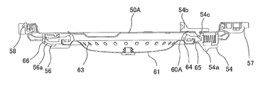
- the inner lid 40A includes a first inner lid 50A attached to the lower surface of the lid body 20, and a surface on the inner hook 30 side of the first inner lid 50A, that is, a second inner lid 60A attached to the lower surface. .
- the first inner lid 50A is located closer to the lid body 20 than the second inner lid 60A, and the second inner lid 60A is located closer to the inner hook 30 than the first inner lid 50A.
- the second inner lid 60A is formed with a pool portion 61 whose central portion protrudes downward, and as shown in FIG. 4, between the first inner lid 50A and the second inner lid 60A.
- a neva reservoir space 61a which is a space for collecting neva, is formed. This neva reservoir space 61a also serves as a path through which steam generated in the inner pot 30 passes.
- a first packing 51 is provided on the outer peripheral portion of the first inner lid 50A so that the inner lid 40A and the inner hook 30 are sealed, that is, the inner hook 30 is sealed.
- an opening / closing valve 62 that opens and closes a connection port (not shown) by moving up and down according to the vapor pressure in the inner pot 30 is provided at the center of the second inner lid 60 ⁇ / b> A.
- a plurality of second communication holes 63 serving as inlets of the neva reservoir space 61a are formed around the opening / closing valve 62.
- the second communication hole 63 is sealed around the second communication hole 63, that is, at the outer peripheral portion, between the first inner lid 50 ⁇ / b> A and the second inner lid 60 ⁇ / b> A, that is, the second reservoir space 61 a is sealed.
- a packing 64 is provided.
- the first inner lid 50A is formed with a plurality of first communication holes 52 that are outlets of the neva reservoir space 61a. That is, the first communication hole 52 and the second communication hole 63 communicate with each other.
- a second locking piece 25 that locks the first inner lid 50 ⁇ / b> A of the inner lid 40 ⁇ / b> A is provided on the front side of the inner side surface of the lid 20.
- the second locking piece 25 is provided with a concave recess 25a.
- two support portions 26 are provided at intervals on the back side of the inner side surface of the lid 20. Between these support portions 26 and the lower surface of the lid 20, a gap of about the thickness of the first convex portion 57 (see FIG. 8 described later) of the first inner lid 50 ⁇ / b> A is formed.
- the number of support portions 26 is not limited to two, and may be three or more. As shown in FIG.
- a peripheral portion 27 that forms a lid steam path 27 a that is a path through which steam generated in the inner pot 30 passes is provided inside the lid 20. Further, a steam port 28 that is an outlet of the lid steam path 27a is formed on the top surface of the lid 20. Further, on the outside of the peripheral portion 27, a third packing 29 is provided for sealing the lid 20 and the first inner lid 50A, that is, for sealing the lid steam path 27a.
- the first communication hole 52 and the lid body vapor path 27a are formed at a position where the lid body 20 and the inner lid 40A are viewed in plan. Yes. That is, the first communication hole 52 serves as an inlet of the lid steam path 27a. Therefore, the neva reservoir space 61a and the lid steam path 27a are in communication, and the second communication hole 63, the first communication hole 52, and the steam port 28 are all in communication.
- the rice cooker 100A accommodates rice and water in the inner pot 30 and heats the inner pot 30 with the heating coil 11 to cook rice. Steam is generated and passes in the order of the second communication hole 63, the neva reservoir space 61a, the first communication hole 52, and the lid steam path 27a, and is discharged from the steam port 28 to the outside of the rice cooker 100A. .
- Neva rises with the steam in the inner pot 30, and the Neva that rises with the steam enters the Neva reservoir space 61a in the inner lid 40A through the second communication hole 63, and the Neva Neva is stored in the storage space 61a.
- the neva and the steam are separated, and the steam passes through the first communication hole 52 and is discharged from the steam port 28 to the outside of the rice cooker 100A.
- the separated Neva is stored in the reservoir 61 with the second inner lid 60A serving as a tray.
- the on-off valve 62 is lowered by its own weight and the weight of the neva, the connecting port is opened, and the neva stored in the neva reservoir space 61a is removed from the inner pot. Because it will be returned to 30, you can cook delicious rice. Also, the neva can be efficiently returned to the inner hook 30.
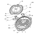
- FIG. 5 is an external perspective view of the inner lid 40A according to Embodiment 1 of the present invention as viewed from the lower surface side
- FIG. 6 is a schematic side view of the inner lid 40A according to Embodiment 1 of the present invention.
- 7 is an exploded perspective view of the inner lid 40A according to the first embodiment of the present invention
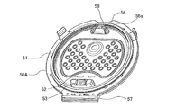
- FIG. 8 is an external perspective view of the first inner lid 50A according to the first embodiment of the present invention.
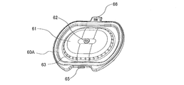
- FIG. 9 is an external perspective view of the second inner lid 60A according to Embodiment 1 of the present invention.
- the inner lid 40A includes the first inner lid 50A and the second inner lid 60A as described above, and the second inner lid 60A is detachably attached to the lower surface of the first inner lid 50A.
- the first inner lid 50 ⁇ / b> A is provided with a first packing 51 on the outer peripheral portion of the lower surface thereof, and a first locking portion 53 on the inner side of the first packing 51.
- locking part 56 is provided.
- locking part 56 are provided in the position which mutually opposes.
- the first locking portion 53 includes a first locking piece 54 that slides (moves) when the second inner lid 60 ⁇ / b> A is attached and detached, and the first locking piece 54.
- a locking piece holder 55 that is slidably held via a spring that is biased toward the center of the inner lid 50A.
- the second locking portion 56 is provided with a concave recess 56a.
- the 1st latching piece 54 is comprised with the syndiotactic polystyrene resin (SPS) which is a material with high steam resistance, and is suppressing the aged deterioration by a vapor
- SPS syndiotactic polystyrene resin
- first communication holes 52 that are rounded rectangular holes are formed inside the first locking portion 53 provided on the lower surface of the first inner lid 50A. .
- the number of first communication holes 52 is not limited to two.
- a first convex portion 57 protruding outward is provided at the outer peripheral end of the first inner lid 50A on the first locking portion 53 side, and the outer peripheral end of the first inner lid 50A.
- a second convex portion 58 protruding outward is provided at a position facing the first convex portion 57.
- the second inner lid 60A is provided with a second packing 64 on the outer peripheral portion of the upper surface thereof. Moreover, as shown in FIG. 9, the center part protrudes below and the reservoir part 61 which forms the neva reservoir space 61a is provided. An open / close valve 62 is provided at the center of the reservoir 61, and a plurality of second communication holes 63, which are circular holes, are formed on the outer periphery of the reservoir 61. Further, a first convex portion 65 and a second convex portion 66 projecting outward are provided at the outer peripheral end of the second inner lid 60A. In addition, the 1st convex part 65 and the 2nd convex part 66 are provided in the position which mutually opposes.
- the on-off valve 62 is made of, for example, heat-resistant silicone rubber, and opens and closes the connection port.
- the open / close valve 62 moves upward by the vapor pressure in the inner pot 30 generated during rice cooking, and the connection port is sealed. And when cooking rice is finished, the weight is lowered by its own weight to open the connection port.
- the reservoir 61 is configured to store rice crackers separated from steam during cooking.
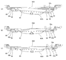
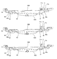
- FIG. 10 is a schematic side view of the inner lid 40A for explaining a method of attaching and detaching the second inner lid 60A to the first inner lid 50A according to Embodiment 1 of the present invention.
- 10A is a diagram showing a state before the second inner lid 60A is attached to the first inner lid 50A
- FIG. 10B is a diagram showing the second inner lid 60A.
- FIG. 10C is a diagram showing a state after completion of attachment to one inner lid 50A
- FIG. 10C is a diagram showing a state before completion of removal of the second inner lid 60A from the first inner lid 50A. .
- the second convex portion 66 of the second inner lid 60A is attached to the first inner lid 50A. Insert into the recess 56a. Thereafter, the first convex portion 65 side of the second inner lid 60A is rotated to the first inner lid 50A side around the second convex portion 66 of the second inner lid 60A. The first convex portion 65 of the inner lid 60A is pressed toward the first locking piece 54 of the first inner lid 50A.
- the first locking piece 54 of the first inner lid 50A interferes with, or comes into contact with, the first convex portion 65 of the second inner lid 60A, and the first convex portion 65 of the second inner lid 60A.
- the first locking piece 54 of the first inner lid 50A pressed against the first inner lid 50A resists the elastic force of the spring that biases the first locking piece 54 toward the center of the first inner lid 50A. It moves to the outside of one inner lid 50A.
- the first convex portion 65 of the second inner lid 60A reaches the concave portion 54c of the first inner lid 50A
- the first locking piece 54 of the first inner lid 50A is located inside the first inner lid 50A.
- the first convex portion 65 of the second inner lid 60A is locked to the concave portion 54c of the first inner lid 50A. In this way, the second inner lid 60A can be attached to the first inner lid 50A.
- the lever portion 54a of the first inner lid 50A is held and the first locking piece 54 is held.
- the first locking piece 54 is moved to the outside of the first inner lid 50A against the elastic force of the spring that biases the first locking piece 54 toward the center of the first inner lid 50A.
- the first convex portion 65 side of the second inner lid 60A is rotated to the side opposite to the first inner lid 50A side, that is, the first convex portion 65 of the second inner lid 60A is moved to the first side. Separate from the first locking piece 54 of one inner lid 50A. Thereafter, the second convex portion 66 of the second inner lid 60A is removed from the concave portion 56a of the first inner lid 50A. In this way, the second inner lid 60A can be removed from the first inner lid 50A.
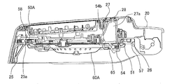
- FIG. 11 is a schematic side view of the periphery of the lid 20 in a state where the second inner lid 60A is attached to the first inner lid 50A of the rice cooker 100A according to Embodiment 1 of the present invention.
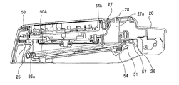
- FIG. 13 is a schematic side view of the periphery of the lid body 20 in a state where the second inner lid 60A is not attached to the first inner lid 50A of the rice cooker 100A according to Embodiment 1 of the present invention.
- FIG. 14 is a schematic vertical cross-sectional view of a state in which a second inner lid 60A is attached to the first inner lid 50A of the rice cooker 100A according to Embodiment 1 of the present invention, and FIG. 14 is an embodiment of the present invention.
- FIG.13 (b) has shown the enlarged view of the part enclosed with the dotted line of the rice cooker 100A shown to Fig.13 (a)
- FIG.14 (b) shows the rice cooker shown to Fig.14 (a).
- the enlarged view of the part enclosed with the dotted line of 100A is shown.
- the first convex portion 57 of the first inner lid 50 ⁇ / b> A is inserted between the lower surface of the lid body 20 and the support portion 26.
- the second convex portion 58 side of the first inner lid 50A is rotated toward the lid body 20 around the first convex portion 57 of the first inner lid 50A, that is, the first inner lid 50A.
- the end of the second convex portion 58 side is pressed toward the second locking piece 25 of the lid 20.
- the second locking piece 25 is urged toward the back side of the lid 20 by a spring.
- the second locking piece 25 of the lid 20 is the second convex portion of the first inner lid 50A. It moves against the elastic force of the spring that interferes with the end portion on the 58 side and urges the second locking piece 25 toward the back side of the lid 20 and moves to the front side of the lid 20.
- the second convex portion 58 of the first inner lid 50A reaches the concave portion 25a of the lid body 20
- the second locking piece 25 of the lid body 20 moves to the back side of the lid body 20
- FIG. 13 the second convex portion 58 of the first inner lid 50 ⁇ / b> A is engaged with the concave portion 25 a of the lid body 20.
- the interference portion 54b of the first inner lid 50A is accommodated in the peripheral portion 27 of the lid 20, that is, in the lid vapor path 27a.
- the first convex portion 57 of the first inner lid 50A is centered.
- the end portion of the first inner lid 50 ⁇ / b> A on the second convex portion 58 side is the second end of the lid body 20.
- the interference portion 54 b of the first inner lid 50 ⁇ / b> A interferes with the peripheral edge portion 27 of the lid body 20 before interfering with the locking piece 25.
- the first inner lid 50A is prevented from further rotating toward the lid 20 side.
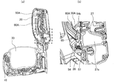
- FIG. 15 is a plan view for explaining the position of the interference portion 54b of the first locking piece 54 of the first inner lid 50A according to Embodiment 1 of the present invention.
- FIG. 15 (a2) shows an enlarged view of a portion surrounded by a dotted line of the first inner lid 50A shown in FIG. 15 (a1)
- FIG. 15 (b2) shows the first part shown in FIG. 15 (b1).
- FIG. 15 (c2) is an enlarged view of a portion surrounded by a dotted line of one inner lid 50A
- FIG. 15 (c2) is an enlarged view of a portion surrounded by a dotted line of the first inner lid 50A shown in FIG. 15 (c1). Show.
- the position of the interference portion 54b of the first locking piece 54 of the first inner lid 50A will be described.
- the position of the interference portion 54b of the first inner lid 50A varies depending on whether or not the second inner lid 60A is attached to the first inner lid 50A.
- the interference portion 54b of the first inner lid 50A is A position that is pushed by the first convex portion 65 of the inner lid 60 ⁇ / b> A and moves to the outside of the first inner lid 50 ⁇ / b> A and is accommodated in the lid vapor path 27 a of the lid 20, that is, the peripheral edge 27 of the lid 20.
- the second convex of the first inner lid 50A is centered on the first convex portion 57 of the first inner lid 50A.
- the portion 58 side is rotated to the lid body 20 side, the end of the first inner lid 50 ⁇ / b> A on the second convex portion 58 side interferes with the second locking piece 25 of the lid body 20.
- the interference portion 54b of one inner lid 50A interferes with the peripheral portion 27 of the lid body 20, and it is easy to recognize that the first inner lid 50A does not rotate toward the lid body 20 side.
- the end portion of the first inner lid 50 ⁇ / b> A on the second convex portion 58 side is pressed toward the second locking piece 25 of the lid body 20 to forcefully attach the first inner lid 50 ⁇ / b> A to the lid body 20. Can be prevented.
- the amount of movement of the first locking piece 54 of the first inner lid 50A required when removing the second inner lid 60A from the first inner lid 50A is such that the inner lid 40A is attached to the lid 20.
- the amount of movement until the interference portion 54 b of the first locking piece 54 interferes with the peripheral edge portion 27 of the lid 20 is larger. That is, in order to remove the second inner lid 60A from the first inner lid 50A, the interference portion 54b of the first inner lid 50A is moved to the lid vapor path 27a of the lid 20 as shown in FIG. It is necessary to move further from the position housed inside to the position outside the first inner lid 50A.
- the first locking piece 54 of the first inner lid 50A is moved to the position where the second inner lid 60A can be removed before the first Since the interference portion 54b of the inner lid 50A interferes with the peripheral portion 27 of the second inner lid 60A, the second inner lid 60A cannot be removed. Accordingly, it is possible to prevent only the second inner lid 60A from being removed when the inner lid 40A is attached to the lid body 20, and to prevent the second inner lid 60A from being forgotten to be attached.
- the first communication hole 52 is formed at a position where the first locking piece 54 is not provided, and is formed at a position outside the moving range of the first locking piece 54. Therefore, the 1st communicating hole 52 is not obstruct
- FIG. 16 is a schematic longitudinal sectional view of the state in which the inner lid 40A is not attached to the lid 20 of the rice cooker 100A according to Embodiment 1 of the present invention.
- FIG.16 (b) has shown the enlarged view of the part enclosed with the dotted line of 100 A of rice cookers shown to Fig.16 (a).
- the second locking piece 25 of the lid body 20 is pushed and moved by the end portion of the inner lid 40A and does not interfere with the flange 31 of the inner hook 30.
- the second locking piece 25 of the lid body 20 moves to the initial position, and the flange of the inner hook 30 is moved. This position is to interfere with 31.
- the lid 20 when the lid 20 is to be closed in a state where the inner lid 40 ⁇ / b> A is not attached to the lid 20, the second locking piece 25 of the lid 20 is in a position where it interferes with the flange 31 of the inner hook 30. Therefore, the lid 20 cannot be closed. Therefore, forgetting to attach the inner lid 40A can be prevented.
- the 2nd inner lid 60A is latched by the 1st latching piece 54 with which the 1st inner lid 50A is equipped, and the 2nd inner lid 60A. Can be attached to the first inner lid 50A. Further, if the first inner lid 50A is attached to the lid 20 in a state where the second inner lid 60A is not attached to the first inner lid 50A, the first locking of the first inner lid 50A is performed. The piece 54 and the lid 20 interfere with each other, and the first inner lid 50 ⁇ / b> A cannot be attached to the lid 20. Therefore, forgetting to attach the second inner lid 60A can be prevented.
- the second inner lid 60A can be attached to the first inner lid 50A by the first locking piece 54, and forgetting to attach the second inner lid 60A can be prevented. There is no need to separately provide a mechanism for attaching the inner lid 60A to the first inner lid 50A and a mechanism for preventing the second inner lid 60A from being forgotten to be attached, and forgetting to attach the second inner lid 60A while reducing costs. Can be prevented.
- Embodiment 2 FIG. Hereinafter, the second embodiment of the present invention will be described. However, the description of (a part of) the same as that of the first embodiment is omitted, and the same reference numerals are given to the same or corresponding parts as those of the first embodiment. Attached.
- FIG. 17 is a schematic longitudinal sectional view of a rice cooker 100B according to Embodiment 2 of the present invention
- FIG. 18 is an external perspective view of the inner lid 40B according to Embodiment 2 of the present invention as viewed from the lower surface side
- FIG. 19 is an external perspective view of the inner lid 40B according to the second embodiment of the present invention as seen from the upper surface side
- FIG. 20 is an exploded perspective view of the inner lid 40B according to the second embodiment of the present invention. It is.
- the structure for locking the second inner lid 60B to the first inner lid 50B is different from the first embodiment.
- a first packing 51 is provided on the outer peripheral surface of the first inner lid 50 ⁇ / b> B on the inner hook 30 side, that is, the lower surface.
- a second locking portion 56 is provided on the inner side.
- locking part 70 is provided in the surface used as the cover body 20 side of the 1st inner cover 50B, ie, an upper surface.
- locking part 56 are provided in the position which mutually opposes.
- the first locking portion 70 includes a first locking piece 71 that slides (moves) when the second inner lid 60B is attached and detached, and the first locking piece 71 via a spring.
- the 1st latching piece 71 is comprised with the syndiotactic polystyrene resin (SPS) which is a material with high steam resistance, and is suppressing the aged deterioration by a vapor
- SPS syndiotactic polystyrene resin
- first communication holes 52 that are rounded rectangular holes are formed inside the first locking portion 70 on the lower surface of the first inner lid 50B.
- the number of first communication holes 52 is not limited to two.
- the 1st convex part 57 which protruded toward the outer side is provided in the outer peripheral end by the side of the 1st latching
- a second convex portion 58 protruding outward is provided at a position facing the first convex portion 57.
- the first locking piece 71 is located on the upper surface of the first inner lid 50B, and a lever portion 71a that is gripped when the user moves, and a claw protruding toward the outside of the first inner lid 50B.
- Part 71b and interference part 71c provided on both side surfaces of first locking piece 71 and projecting further than claw part 71b.
- the locking piece holder 72 is positioned on the upper surface of the first inner lid 50B, and includes a concave recess 72a and a hole 72b through which the interference portion 71c enters and exits. Further, the locking piece holder 72 biases the first locking piece 71 toward the outside of the first inner lid 50B by a spring.
- the second inner lid 60B is provided with a second packing 64 on the surface on the first inner lid 50B side, that is, on the outer peripheral portion of the upper surface. Moreover, the center part protrudes below and the reservoir part 61 which forms the neva reservoir space 61a is provided.
- An open / close valve 62 is provided at the center of the reservoir 61, and a plurality of second communication holes 63, which are circular holes, are formed on the outer periphery of the reservoir 61. Further, a first convex portion 80 and a second convex portion 66 projecting outward are provided at the outer peripheral end of the second inner lid 60B.
- the 1st convex part 80 and the 2nd convex part 66 are provided in the position which mutually opposes.
- the first convex portion 80 protrudes toward the outside of the second inner lid 60B, and further includes a claw portion 80a whose end portion protrudes toward the upper surface side.
- FIG. 21 is a schematic side view of the inner lid 40B for explaining a method of attaching and detaching the second inner lid 60B to the first inner lid 50B according to Embodiment 2 of the present invention.
- FIG. 21A is a diagram illustrating a state before the second inner lid 60B is completely attached to the first inner lid 50B
- FIG. 21B is a diagram illustrating the second inner lid 60B. It is a figure which shows the state after completion of attachment to the one inner cover 50B
- FIG.21 (c) is a figure which shows the state before the removal from the 1st inner cover 50B of the 2nd inner cover 60B is completed. .
- the second convex portion 66 of the second inner lid 60B is attached to the first inner lid 50B. Insert into the recess 56a. Thereafter, the first convex portion 80 side of the second inner lid 60B is rotated to the first inner lid 50B side around the second convex portion 66 of the second inner lid 60B. The first convex portion 80 of the inner lid 60B is pressed toward the first locking piece 71 of the first inner lid 50B.
- the first locking piece 71 of the first inner lid 50B interferes with, that is, comes into contact with, the claw portion 80a of the first convex portion 80 of the second inner lid 60B.
- the first locking piece 71 pushed by 80a resists the elastic force of the spring that urges the first locking piece 71 in the outward direction of the first inner lid 50B. Move inward.
- the bottom surface of the claw portion 80a of the first convex portion 80 exceeds the tip end portion of the claw portion 71b of the first locking piece 71, the first locking piece 71 moves to the outside of the first inner lid 50B. As shown in FIG.
- the claw portion 80a of the first convex portion 80 of the second inner lid 60B is locked to the claw portion 71b of the first locking piece 71 of the first inner lid 50B.
- the second inner lid 60B can be attached to the first inner lid 50B.
- the lever portion 71a of the first inner lid 50B is held and the first locking piece 71 is held. Is moved to the inside of the first inner lid 50B. Then, when the state in which the claw portion 80a of the first convex portion 80 of the second inner lid 60B is locked to the claw portion 71b of the first locking piece 71 of the first inner lid 50B is released, The first convex portion 80 side of the first inner lid 50B is rotated to the opposite side to the first inner lid 50B side around the second convex portion 66 of the second inner lid 60B.
- the first convex portion 80 of the inner lid 60B is separated from the first locking piece 71 of the first inner lid 50B. Thereafter, the second convex portion 66 of the second inner lid 60B is removed from the concave portion 56a of the first inner lid 50B. In this way, the second inner lid 60B can be removed from the first inner lid 50B.
- FIG. 22 is a schematic longitudinal sectional view of the periphery of the lid body 20 in a state where the second inner lid 60B is attached to the first inner lid 50B of the rice cooker 100B according to the second embodiment of the present invention.
- 23 is a schematic longitudinal sectional view of the periphery of the lid 20 in a state where the second inner lid 60B is not attached to the first inner lid 50B of the rice cooker 100B according to Embodiment 2 of the present invention.
- FIG.23 (b) has shown the enlarged view of the part enclosed with the dotted line of the rice cooker 100B shown to Fig.23 (a).
- the first convex portion 57 of the first inner lid 50 ⁇ / b> B is inserted between the lower surface of the lid body 20 and the support portion 26.
- the second convex portion 58 side of the first inner lid 50B is rotated toward the lid body 20 around the first convex portion 57 of the first inner lid 50A, that is, the first inner lid 50B.
- the end of the second convex portion 58 side is pressed toward the second locking piece 25 of the lid 20.
- the second locking piece 25 is urged toward the back side of the lid 20 by a spring.
- the second locking piece 25 of the lid 20 is the second convex portion of the first inner lid 50B. It moves against the elastic force of the spring that interferes with the end portion on the 58 side and urges the second locking piece 25 toward the back side of the lid 20 and moves to the front side of the lid 20. And if the 2nd convex part 58 of the 1st inner cover 50B reaches
- the second convex portion 58 of the first inner lid 50 ⁇ / b> B is engaged with the concave portion 25 a of the lid body 20.
- the inner lid 40B can be attached to the lid body 20.
- the lever portion 71a, the claw portion 71b, and the interference portion 71c which are the entire first locking piece 71 of the first inner lid 50B, are located in the peripheral portion 27 of the lid body 20, that is, the lid body vapor path. 27a.
- the end portion on the second convex portion 58 side of the first inner lid 50B is as shown in FIG.
- the interference part 71 c of the first inner lid 50 ⁇ / b> B interferes with the peripheral edge 27 of the lid 20.
- the first inner lid 50B is prevented from further rotating toward the lid 20 side.
- FIG. 24 is a plan view for explaining the position of the interference portion 71c of the first locking piece 71 of the first inner lid 50B according to Embodiment 2 of the present invention.
- FIG. 24 (a2) shows an enlarged view of the portion surrounded by the dotted line of the first inner lid 50B shown in FIG. 24 (a1)
- FIG. 24 (b2) shows the first part shown in FIG. 24 (b1).
- FIG. 24 (c2) is an enlarged view of a portion surrounded by a dotted line of one inner lid 50B
- FIG. 24 (c2) is an enlarged view of a portion surrounded by a dotted line of the first inner lid 50B shown in FIG. 24 (c1). Show.
- the position of the interference portion 71c of the first locking piece 71 of the first inner lid 50B will be described.
- the position of the interference portion 71c of the first inner lid 50B varies depending on whether or not the second inner lid 60B is attached to the first inner lid 50B. If the second inner lid 60B is attached to the first inner lid 50B as shown in FIG. 24 (a2), the interference portion 71c of the first inner lid 50B A position that is pushed by the claw portion 80a of the first convex portion 80 of the inner lid 60B, moves to the inside of the first inner lid 50B, and is accommodated in the lid vapor path 27a of the lid 20, that is, the lid 20 It will be the position which does not interfere with the peripheral part 27.
- the interference portion 71c of the first inner lid 50B moves to the initial position. Then, it is a position that interferes with the peripheral edge 27 of the lid 20.
- the interference portion of the first inner lid 50B Since 71 c is at a position where it interferes with the peripheral edge portion 27 of the lid body 20, the first inner lid 50 ⁇ / b> B cannot be attached to the lid body 20. Therefore, forgetting to attach the second inner lid 60B can be prevented.
- the second convex of the first inner lid 50B is centered on the first convex portion 57 of the first inner lid 50A.
- the portion 58 side is rotated to the lid body 20 side, the end of the first inner lid 50B on the second convex portion 58 side interferes with the second locking piece 25 of the lid body 20 before
- the interference portion 71c of one inner lid 50B interferes with the peripheral portion 27 of the lid body 20, and it is easy to recognize that the first inner lid 50B does not rotate toward the lid body 20 side. Therefore, the end of the first inner lid 50B on the second convex portion 58 side is pressed toward the second locking piece 25 of the lid 20 so as to forcefully attach the first inner lid 50B to the lid 20. Can be prevented.
- the first locking piece 71 is housed in the lid vapor path 27a and cannot be touched. Therefore, in the state where the first inner lid 50B is attached to the lid body 20, it is not possible to remove only the second inner lid 60B. This prevents the second inner lid 60B from being removed when the first inner lid 50B is attached to the lid body, and prevents forgetting to attach the second inner lid 60B. it can.
- the first communication hole 52 is formed at a position where the first locking piece 71 is not provided, and is formed at a position outside the moving range of the first locking piece 71. Therefore, the 1st communicating hole 52 is not obstruct
- the 2nd inner lid 60B is latched by the 1st latching piece 71 with which the 1st inner lid 50B is provided, and the 2nd inner lid 60B. Can be attached to the first inner lid 50B. Further, if the first inner lid 50B is attached to the lid body 20 in a state where the second inner lid 60B is not attached to the first inner lid 50B, the first locking of the first inner lid 50B is performed. Since the piece 71 and the lid 20 interfere with each other, forgetting to attach the second inner lid 60B can be prevented.
- the second inner lid 60B can be attached to the first inner lid 50B by the first locking piece 71 and the forgetting to attach the second inner lid 60B can be prevented, It is not necessary to provide a mechanism for attaching the inner lid 60B to the first inner lid 50B and a mechanism for preventing the forgetting to attach the second inner lid 60B, and forgetting to attach the second inner lid 60B while reducing costs. Can be prevented.
Landscapes
- Engineering & Computer Science (AREA)
- Food Science & Technology (AREA)
- Cookers (AREA)
Abstract
炊飯器(100A)は、内釜(30)を収容する本体(10)と、本体に開閉自在に設けられる蓋体(20)と、蓋体の下面に取り付けられ、おネバ溜め空間(61a)を有する内蓋(40A)と、を備え、内蓋は、蓋体の下面に取り付けられる第一の内蓋(50A)と、第一の内蓋の下面に取り付けられる第二の内蓋(60A)と、を備え、第一の内蓋は、第二の内蓋を係止する第一の係止片(54)を備え、第一の係止片は、第二の内蓋が第一の内蓋に取り付けられていない状態では、蓋体と干渉する位置にあり、第二の内蓋が第一の内蓋に取り付けられている状態では、蓋体と干渉しない位置にあるものである。
Description
本発明は、液状物の受け皿の取り付け忘れを防止する炊飯器に関するものである。
従来の炊飯器において、内釜を取り出し自在に配置する本体を備え、この本体に内釜を覆う蓋体が開閉自在に設けられている。蓋体には、内釜の上端開口を閉塞する第一の内蓋が着脱自在に設けられている。また、第一の内蓋の内釜側となる下面には、液状物であるおネバを分離して戻す受け皿(第二の内蓋)がさらに着脱自在に設けられている。なお、第二の内蓋は、第一の内蓋に設けられた排気通路の入口、つまり排気孔の目詰まりを防止するフィルタの役割を兼ねる。
しかし、上記の炊飯器は、ユーザの誤使用により第一の内蓋に第二の内蓋を取り付け忘れた状態で炊飯処理が実行されることがある。この場合、発生したおネバを分離することができず、ふきこぼれが発生するという問題があった。
そこで、従来、下側カバーの取り付け忘れを防止する炊飯器が提案されている(たとえば、特許文献1参照)。
特許文献1は、第一の内蓋から第二の内蓋を取り外した状態で内釜または本体に干渉する干渉位置、つまり接触する位置に移動し、第二の内蓋の取り付けた状態で内釜または本体に干渉しない非干渉位置、つまり接触しない位置に移動する干渉部材を備えている。そして、第二の内蓋を取り外すと干渉部材が非干渉位置から干渉位置に移動するため、この状態で蓋体を閉じようとすると干渉部材が内釜または本体に干渉する。その結果、第二の内蓋が取り付けられていない状態をユーザに認識させることができ、第二の内蓋が取り付けられていない状態で調理が行われるという誤使用を防止できる。
特許文献1は、第一の内蓋から第二の内蓋を取り外した状態で内釜または本体に干渉する干渉位置、つまり接触する位置に移動し、第二の内蓋の取り付けた状態で内釜または本体に干渉しない非干渉位置、つまり接触しない位置に移動する干渉部材を備えている。そして、第二の内蓋を取り外すと干渉部材が非干渉位置から干渉位置に移動するため、この状態で蓋体を閉じようとすると干渉部材が内釜または本体に干渉する。その結果、第二の内蓋が取り付けられていない状態をユーザに認識させることができ、第二の内蓋が取り付けられていない状態で調理が行われるという誤使用を防止できる。
しかし、特許文献1は、第二の内蓋を第一の内蓋に取り付ける機構とは別に、第二の内蓋の取り付け忘れを防止する機構を設ける必要があるため、コストがかかるという課題があった。
本発明は、以上のような課題を解決するためになされたもので、コストを抑制しつつ、下側カバーの取り付け忘れを防止することができる炊飯器を提供することを目的としている。
本発明に係る炊飯器は、内釜を収容する本体と、前記本体に開閉自在に設けられる蓋体と、前記蓋体の下面に取り付けられ、おネバ溜め空間を有する内蓋と、を備え、前記内蓋は、前記蓋体の下面に取り付けられる第一の内蓋と、前記第一の内蓋の下面に取り付けられる第二の内蓋と、を備え、前記第一の内蓋は、前記第二の内蓋を係止する第一の係止片を備え、前記第一の係止片は、前記第二の内蓋が前記第一の内蓋に取り付けられていない状態では、前記蓋体と干渉する位置にあり、前記第二の内蓋が前記第一の内蓋に取り付けられている状態では、前記蓋体と干渉しない位置にあるものである。
本発明に係る炊飯器によれば、第一の内蓋が備える第一の係止片により、第二の内蓋を係止し、第二の内蓋を第一の内蓋に取り付けることができる。また、第二の内蓋が第一の内蓋に取り付けられていない状態で第一の内蓋を蓋体に取り付けようとすると、第一の内蓋の第一の係止片と蓋体とが干渉し、第一の内蓋を蓋体に取り付けることができない。そのため、第二の内蓋の取り付け忘れを防止することができる。つまり、第一の係止片により、第二の内蓋を第一の内蓋に取り付けることができ、第二の内蓋の取り付け忘れを防止することができるため、第二の内蓋を第一の内蓋に取り付ける機構と第二の内蓋の取り付け忘れを防止する機構とを別に設ける必要がなく、コストを抑制しつつ、第二の内蓋の取り付け忘れを防止することができる。
以下、本発明の実施の形態を図面に基づいて説明する。なお、以下に説明する実施の形態によって本発明が限定されるものではない。また、以下の図面では各構成部材の大きさの関係が実際のものとは異なる場合がある。
実施の形態1.
図1は、本発明の実施の形態1に係る炊飯器100Aの外観斜視図であり、図2は、本発明の実施の形態1に係る炊飯器100Aの内蓋40Aを取り外した状態の外観斜視図であり、図3は、本発明の実施の形態1に係る炊飯器100Aの縦断面概略図であり、図4は、本発明の実施の形態1に係る炊飯器100Aの蒸気経路周辺の縦断面概略図である。
図1~図3に示すように、本実施の形態1に係る炊飯器100Aは、内部に米などの調理物である被加熱物を保持する有底筒状の内釜30が取り出し自在に収容され、内釜30を誘導加熱する加熱手段である加熱コイル11を有する箱体形状の本体10と、本体10のヒンジ部12に開閉自在に設けられた蓋体20と、蓋体20の内釜30側となる面、つまり下面に着脱自在に取り付けられ、蓋体20で本体10の上面を閉じた際に、内釜30の上部開口を閉塞する内蓋40Aとを備えている。
図1は、本発明の実施の形態1に係る炊飯器100Aの外観斜視図であり、図2は、本発明の実施の形態1に係る炊飯器100Aの内蓋40Aを取り外した状態の外観斜視図であり、図3は、本発明の実施の形態1に係る炊飯器100Aの縦断面概略図であり、図4は、本発明の実施の形態1に係る炊飯器100Aの蒸気経路周辺の縦断面概略図である。
図1~図3に示すように、本実施の形態1に係る炊飯器100Aは、内部に米などの調理物である被加熱物を保持する有底筒状の内釜30が取り出し自在に収容され、内釜30を誘導加熱する加熱手段である加熱コイル11を有する箱体形状の本体10と、本体10のヒンジ部12に開閉自在に設けられた蓋体20と、蓋体20の内釜30側となる面、つまり下面に着脱自在に取り付けられ、蓋体20で本体10の上面を閉じた際に、内釜30の上部開口を閉塞する内蓋40Aとを備えている。
図3に示すように、内釜30は、外周面の上側に、外側に向かって突出したフランジ31が外周に沿って設けられている。加熱コイル11は、それぞれ円環状に形成され、内釜30が収容される開口の底部に配置されている。その底部の中央には、加熱コイル11により誘導加熱される内釜30の温度を検出する温度センサー13が設置されている。
本体10の前面には、蓋体20を開ける際に押下される開閉ボタン14が設けられている。この開閉ボタン14を押下すると、蓋体20と本体10との係止が解除されて、蓋体20を開けることができる。また、本体10の内部の背面側には、商用電源を高周波電力に変換して加熱コイル11に供給するための回路が実装された電源基板15が設けられている。この電源基板15は、インバーター回路を構成するスイッチング素子などの部品で構成されている。
蓋体20の上面の前面側には、炊飯ボタンなどの各種操作ボタンを備えた操作パネル21が設けられている。蓋体20の内部には、操作パネル21の各種入力スイッチ、液晶パネルが実装された操作基板22が設けられている。操作基板22は、操作パネル21からの入力に基づいて電源基板15に制御信号を出力するとともに、液晶パネルに炊飯器100Aの動作状態などを表示させる。なお、操作基板22を構成する回路は、その機能を実現する回路デバイスのようなハードウェアで構成することもできるし、CPU、マイコンなどの演算装置とその動作を規定するソフトウェアで構成することもできる。また、蓋体20の下面には、内釜30内の温度を検知する蓋センサー23と、本体10内に収容される内釜30内を上方から加熱するための蓋ヒーター24と、が設けられている。
内蓋40Aは、蓋体20の下面に取り付けられる第一の内蓋50Aと、第一の内蓋50Aの内釜30側となる面、つまり下面に取り付けられる第二の内蓋60Aとからなる。そして、第一の内蓋50Aは第二の内蓋60Aよりも蓋体20側に位置し、第二の内蓋60Aは第一の内蓋50Aよりも内釜30側に位置している。また、第二の内蓋60Aには、中央部が下方に突出した溜まり部61が形成されており、図4に示すように、第一の内蓋50Aと第二の内蓋60Aとの間には、おネバを溜める空間であるおネバ溜め空間61aが形成されている。このおネバ溜め空間61aは、内釜30内で発生した蒸気が通過する経路の役割も果たしている。
第一の内蓋50Aの外周部には、内蓋40Aと内釜30との間を密閉状態、つまり内釜30内を密閉状態にする第一のパッキン51が設けられている。図3に示すように、第二の内蓋60Aの中央には、内釜30内の蒸気圧に応じて上下に移動して連結口(図示せず)を開閉する開閉弁62が設けられており、その開閉弁62の周りには、おネバ溜め空間61aの入口である複数の第二の連通孔63が形成されている。さらに、第二の連通孔63の周り、つまり外周部には第一の内蓋50Aと第二の内蓋60Aとの間を密閉状態、つまりおネバ溜め空間61aを密閉状態にする第二のパッキン64が設けられている。また、図4に示すように、第一の内蓋50Aには、おネバ溜め空間61aの出口である複数の第一の連通孔52が形成されている。つまり、第一の連通孔52と第二の連通孔63とは連通している。
図3に示すように、蓋体20の内側側面の前面側には、内蓋40Aの第一の内蓋50Aを係止する第二の係止片25が設けられている。この第二の係止片25には、凹形状の凹部25aが設けられている。また、図2に示すように、蓋体20の内側側面の背面側には、2つの支持部26が間隔を開けて設けられている。これら支持部26と蓋体20の下面との間には第一の内蓋50Aの第一の凸部57(後述する図8参照)の厚さ程度の隙間が形成されている。なお、支持部26の数は2つに限定されず、3つ以上でもよい。また、図4に示すように、蓋体20の内部には、内釜30内で発生した蒸気が通過する経路である蓋体蒸気経路27aを形成する周縁部27が設けられている。また、蓋体20の上面には、蓋体蒸気経路27aの出口である蒸気口28が形成されている。また、周縁部27の外側には、蓋体20と第一の内蓋50Aとの間を密閉状態、つまり蓋体蒸気経路27aを密閉状態にする第三のパッキン29が設けられている。
なお、内蓋40Aが蓋体20の下面に取り付けられた状態において、蓋体20および内蓋40Aを平面視して第一の連通孔52と蓋体蒸気経路27aとが重なる位置に形成されている。つまり、第一の連通孔52は蓋体蒸気経路27aの入口となる。そのため、おネバ溜め空間61aと蓋体蒸気経路27aとは連通しており、第二の連通孔63と第一の連通孔52と蒸気口28とは全て連通している。
ここで、炊飯器100Aは、内釜30内に米と水とを収容して加熱コイル11によって内釜30を加熱してご飯を炊き上げるが、炊飯中においては、内釜30内では主に蒸気が発生して、第二の連通孔63、おネバ溜め空間61a、第一の連通孔52、蓋体蒸気経路27aの順で通過し、蒸気口28から炊飯器100Aの外部へ排出される。
そして、炊飯中には、蒸気とともにおネバが内釜30内を上昇し、蒸気とともに上昇したおネバは、第二の連通孔63から内蓋40A内のおネバ溜め空間61aに入り、おネバ溜め空間61aにおネバが溜め込まれる。このときおネバと蒸気とは分離され、蒸気は第一の連通孔52を通過して蒸気口28から炊飯器100Aの外部へ排出される。
一方、分離されたおネバは第二の内蓋60Aが受け皿となり、溜まり部61に溜め込まれることになる。そして、炊飯終了後に内釜30内の圧力が下がると、開閉弁62は自重とおネバの重さにより下がり、連結口が開いてそこからおネバ溜め空間61a内に溜め込まれたおネバが内釜30内に戻されることになるため、美味しいご飯を炊き上げることができる。また、おネバを内釜30内に効率的に戻すことができる。
図5は、本発明の実施の形態1に係る内蓋40Aを下面側から見た外観斜視図であり、図6は、本発明の実施の形態1に係る内蓋40Aの側面概略図であり、図7は、本発明の実施の形態1に係る内蓋40Aの分解斜視図であり、図8は、本発明の実施の形態1に係る第一の内蓋50Aの外観斜視図であり、図9は、本発明の実施の形態1に係る第二の内蓋60Aの外観斜視図である。
次に、本実施の形態1に係る内蓋40Aについて図5~図9を用いて詳細に説明する。
内蓋40Aは、上記の通り第一の内蓋50Aと第二の内蓋60Aとからなり、第二の内蓋60Aは第一の内蓋50Aの下面に対して着脱自在に取り付けられる。
内蓋40Aは、上記の通り第一の内蓋50Aと第二の内蓋60Aとからなり、第二の内蓋60Aは第一の内蓋50Aの下面に対して着脱自在に取り付けられる。
図8に示すように、第一の内蓋50Aは、その下面の外周部に第一のパッキン51が設けられており、その第一のパッキン51よりも内側には第一の係止部53および第二の係止部56が設けられている。なお、第一の係止部53と第二の係止部56とは、互いに対向する位置に設けられている。図7に示すように、第一の係止部53は、第二の内蓋60Aの着脱時にスライド(移動)する第一の係止片54と、第一の係止片54を第一の内蓋50Aの中心方向に付勢するバネを介してスライド自在に保持する係止片ホルダー55とを備えている。また、第二の係止部56には、凹形状の凹部56aが設けられている。ここで、第一の係止片54は、耐蒸気性の高い材料であるシンジオタクチックポリスチレン樹脂(SPS)で構成されており、蒸気による経年劣化を抑制している。
また、第一の内蓋50Aの下面に設けられている第一の係止部53よりも内側には、角丸な長方形状の孔である第一の連通孔52が二つ形成されている。なお、第一の連通孔52の数は二つに限定されない。また、第一の内蓋50Aの第一の係止部53側の外周端には、外側に向かって突出した第一の凸部57が設けられており、第一の内蓋50Aの外周端の第一の凸部57と対向する位置には、外側に向かって突出した第二の凸部58が設けられている。
第一の係止片54は、図6に示すように、第一の内蓋50Aの下面側に位置し、ユーザが移動させる際に把持するレバー部54aと、第一の内蓋50Aの蓋体20側となる面、つまり上面側に位置し、レバー部54aに連動して移動する干渉部54bと、第一の内蓋50Aの下面側に位置する凹形状の凹部54cとを備えている。
第二の内蓋60Aは、その上面の外周部に第二のパッキン64が設けられている。また、図9に示すように、中央部が下方に突出し、おネバ溜め空間61aを形成する溜まり部61が設けられている。溜まり部61の中央には開閉弁62が設けられており、溜まり部61の外周には円形状の孔である第二の連通孔63が複数形成されている。また、第二の内蓋60Aの外周端には、外側に向かって突出した第一の凸部65および第二の凸部66が設けられている。なお、第一の凸部65と第二の凸部66とは、互いに対向する位置に設けられている。
開閉弁62は、例えば耐熱性を有するシリコンゴムなどで構成されており、連結口を開閉するものであり、炊飯時に発生する内釜30内の蒸気圧で上方に移動して連結口を密閉状態とし、炊飯が終了したときには、自重で下がって連結口を開状態とする。また、溜まり部61には、炊飯時に蒸気から分離されたおネバが溜まるようになっている。
図10は、本発明の実施の形態1に係る第二の内蓋60Aの第一の内蓋50Aへの着脱方法を説明する内蓋40Aの側面概略図である。なお、図10(a)は、第二の内蓋60Aの第一の内蓋50Aへの取り付け完了前の状態を示す図であり、図10(b)は、第二の内蓋60Aの第一の内蓋50Aへの取り付け完了後の状態を示す図であり、図10(c)は、第二の内蓋60Aの第一の内蓋50Aからの取り外し完了前の状態を示す図である。
次に、第二の内蓋60Aの第一の内蓋50Aへの着脱方法について図10を用いて説明する。
第二の内蓋60Aを第一の内蓋50Aに取り付けるには、まず、図10(a)に示すように第二の内蓋60Aの第二の凸部66を第一の内蓋50Aの凹部56aに挿入する。その後、第二の内蓋60Aの第二の凸部66を中心として第二の内蓋60Aの第一の凸部65側を第一の内蓋50A側に回動させる、つまり、第二の内蓋60Aの第一の凸部65を第一の内蓋50Aの第一の係止片54に向かって押し付ける。すると、第一の内蓋50Aの第一の係止片54は第二の内蓋60Aの第一の凸部65と干渉、つまり接触し、第二の内蓋60Aの第一の凸部65に押された第一の内蓋50Aの第一の係止片54は、第一の係止片54を第一の内蓋50Aの中心方向に付勢するバネの弾性力に抗して第一の内蓋50Aの外側に移動する。第二の内蓋60Aの第一の凸部65が第一の内蓋50Aの凹部54cに到達したら、第一の内蓋50Aの第一の係止片54が第一の内蓋50Aの内側に移動し、図10(b)に示すように第二の内蓋60Aの第一の凸部65が第一の内蓋50Aの凹部54cに係止される。このようにして、第二の内蓋60Aを第一の内蓋50Aに取り付けることができる。
第二の内蓋60Aを第一の内蓋50Aに取り付けるには、まず、図10(a)に示すように第二の内蓋60Aの第二の凸部66を第一の内蓋50Aの凹部56aに挿入する。その後、第二の内蓋60Aの第二の凸部66を中心として第二の内蓋60Aの第一の凸部65側を第一の内蓋50A側に回動させる、つまり、第二の内蓋60Aの第一の凸部65を第一の内蓋50Aの第一の係止片54に向かって押し付ける。すると、第一の内蓋50Aの第一の係止片54は第二の内蓋60Aの第一の凸部65と干渉、つまり接触し、第二の内蓋60Aの第一の凸部65に押された第一の内蓋50Aの第一の係止片54は、第一の係止片54を第一の内蓋50Aの中心方向に付勢するバネの弾性力に抗して第一の内蓋50Aの外側に移動する。第二の内蓋60Aの第一の凸部65が第一の内蓋50Aの凹部54cに到達したら、第一の内蓋50Aの第一の係止片54が第一の内蓋50Aの内側に移動し、図10(b)に示すように第二の内蓋60Aの第一の凸部65が第一の内蓋50Aの凹部54cに係止される。このようにして、第二の内蓋60Aを第一の内蓋50Aに取り付けることができる。
一方、第二の内蓋60Aを第一の内蓋50Aから取り外すには、図10(c)に示すように第一の内蓋50Aのレバー部54aを把持して第一の係止片54を、第一の係止片54を第一の内蓋50Aの中心方向に付勢するバネの弾性力に抗して第一の内蓋50Aの外側に移動させる。そして、第二の内蓋60Aの第一の凸部65が第一の内蓋50Aの凹部54cに係止された状態が解除されたら、第二の内蓋60Aの第二の凸部66を中心として第二の内蓋60Aの第一の凸部65側を第一の内蓋50A側とは反対側に回動させる、つまり、第二の内蓋60Aの第一の凸部65を第一の内蓋50Aの第一の係止片54から離す。その後、第二の内蓋60Aの第二の凸部66を第一の内蓋50Aの凹部56aから抜く。このようにして、第二の内蓋60Aを第一の内蓋50Aから取り外すことができる。
図11は、本発明の実施の形態1に係る炊飯器100Aの第一の内蓋50Aに第二の内蓋60Aが取り付けられている状態の蓋体20周辺の側面概略図であり、図12は、本発明の実施の形態1に係る炊飯器100Aの第一の内蓋50Aに第二の内蓋60Aが取り付けられていない状態の蓋体20周辺の側面概略図であり、図13は、本発明の実施の形態1に係る炊飯器100Aの第一の内蓋50Aに第二の内蓋60Aが取り付けられている状態の縦断面概略図であり、図14は、本発明の実施の形態1に係る炊飯器100Aの第一の内蓋50Aに第二の内蓋60Aが取り付けられていない状態の縦断面概略図である。なお、図13(b)は、図13(a)に示す炊飯器100Aの点線で囲まれた部分の拡大図を示しており、図14(b)は、図14(a)に示す炊飯器100Aの点線で囲まれた部分の拡大図を示している。
次に、内蓋40Aの蓋体20への着脱方法について図11~図14を用いて説明する。
内蓋40Aを蓋体20に取り付けるには、まず第一の内蓋50Aの第一の凸部57を蓋体20の下面と支持部26との間に挿入する。その後、第一の内蓋50Aの第一の凸部57を中心として第一の内蓋50Aの第二の凸部58側を蓋体20側に回動させる、つまり、第一の内蓋50Aの第二の凸部58側の端部を蓋体20の第二の係止片25に向かって押し付ける。第二の係止片25は、バネにより蓋体20の背面側へ付勢される。
内蓋40Aを蓋体20に取り付けるには、まず第一の内蓋50Aの第一の凸部57を蓋体20の下面と支持部26との間に挿入する。その後、第一の内蓋50Aの第一の凸部57を中心として第一の内蓋50Aの第二の凸部58側を蓋体20側に回動させる、つまり、第一の内蓋50Aの第二の凸部58側の端部を蓋体20の第二の係止片25に向かって押し付ける。第二の係止片25は、バネにより蓋体20の背面側へ付勢される。
このとき、第二の内蓋60Aが第一の内蓋50Aに取り付けられている状態であれば、蓋体20の第二の係止片25は第一の内蓋50Aの第二の凸部58側の端部と干渉し、第二の係止片25を蓋体20の背面側へ付勢するバネの弾性力に抗して押されて蓋体20の前面側に移動する。そして、第一の内蓋50Aの第二の凸部58が蓋体20の凹部25aに到達したら、蓋体20の第二の係止片25が蓋体20の背面側に移動し、図11および図13に示すように第一の内蓋50Aの第二の凸部58が蓋体20の凹部25aに係止される。このようにして、内蓋40Aを蓋体20に取り付けることができる。なお、このとき、第一の内蓋50Aの干渉部54bは蓋体20の周縁部27内、つまり蓋体蒸気経路27a内に収納されている。
一方、第二の内蓋60Aが第一の内蓋50Aに取り付けられていない状態であれば、図12および図14に示すように、第一の内蓋50Aの第一の凸部57を中心として第一の内蓋50Aの第二の凸部58側を蓋体20側に回動させると、第一の内蓋50Aの第二の凸部58側の端部が蓋体20の第二の係止片25と干渉する前に、第一の内蓋50Aの干渉部54bが蓋体20の周縁部27と干渉する。そして、第一の内蓋50Aがそれ以上蓋体20側に回動しないようになっている。
図15は、本発明の実施の形態1に係る第一の内蓋50Aの第一の係止片54の干渉部54bの位置を説明する平面視図である。なお、図15(a2)は図15(a1)に示す第一の内蓋50Aの点線で囲まれた部分の拡大図を示しており、図15(b2)は図15(b1)に示す第一の内蓋50Aの点線で囲まれた部分の拡大図を示しており、図15(c2)は図15(c1)に示す第一の内蓋50Aの点線で囲まれた部分の拡大図を示している。
ここで、第一の内蓋50Aの第一の係止片54の干渉部54bの位置について説明する。
図15に示すように、第一の内蓋50Aの干渉部54bの位置は、第二の内蓋60Aが第一の内蓋50Aに取り付けられている状態かどうかによって変わる。そして、図15(a2)に示すように、第二の内蓋60Aが第一の内蓋50Aに取り付けられている状態であれば、第一の内蓋50Aの干渉部54bは、第二の内蓋60Aの第一の凸部65によって押されて第一の内蓋50Aの外側に移動し、蓋体20の蓋体蒸気経路27a内に収納される位置、つまり蓋体20の周縁部27と干渉しない位置となる。一方、図15(b2)に示すように、第二の内蓋60Aが第一の内蓋50Aに取り付けられていない状態であれば、第一の内蓋50Aの干渉部54bは初期位置に移動し、蓋体20の周縁部27と干渉する位置となる。
図15に示すように、第一の内蓋50Aの干渉部54bの位置は、第二の内蓋60Aが第一の内蓋50Aに取り付けられている状態かどうかによって変わる。そして、図15(a2)に示すように、第二の内蓋60Aが第一の内蓋50Aに取り付けられている状態であれば、第一の内蓋50Aの干渉部54bは、第二の内蓋60Aの第一の凸部65によって押されて第一の内蓋50Aの外側に移動し、蓋体20の蓋体蒸気経路27a内に収納される位置、つまり蓋体20の周縁部27と干渉しない位置となる。一方、図15(b2)に示すように、第二の内蓋60Aが第一の内蓋50Aに取り付けられていない状態であれば、第一の内蓋50Aの干渉部54bは初期位置に移動し、蓋体20の周縁部27と干渉する位置となる。
このように、第二の内蓋60Aが第一の内蓋50Aに取り付けられていない状態では、第一の内蓋50Aを蓋体20に取り付けようとすると、第一の内蓋50Aの干渉部54bが蓋体20の周縁部27と干渉する位置にあるため、第一の内蓋50Aを蓋体20に取り付けられないようになっている。そのため、第二の内蓋60Aの取り付け忘れを防止することができる。
また、第二の内蓋60Aが第一の内蓋50Aに取り付けられていない状態では、第一の内蓋50Aの第一の凸部57を中心として第一の内蓋50Aの第二の凸部58側を蓋体20側に回動させると、第一の内蓋50Aの第二の凸部58側の端部が蓋体20の第二の係止片25と干渉する前に、第一の内蓋50Aの干渉部54bが蓋体20の周縁部27と干渉するようになっており、第一の内蓋50Aが蓋体20側に回動しないことを認識しやすくなっている。そのため、第一の内蓋50Aを蓋体20に無理矢理取り付けようとして第一の内蓋50Aの第二の凸部58側の端部を蓋体20の第二の係止片25に向かって押し付けるのを防止することができる。
また、第二の内蓋60Aを第一の内蓋50Aから取り外す際に必要な第一の内蓋50Aの第一の係止片54の移動量は、内蓋40Aが蓋体20に取り付けられた状態で第一の係止片54の干渉部54bが蓋体20の周縁部27と干渉するまでの移動量よりも大きい。つまり、第二の内蓋60Aを第一の内蓋50Aから取り外すには、図15(c2)に示すように、第一の内蓋50Aの干渉部54bを蓋体20の蓋体蒸気経路27a内に収納される位置からさらに第一の内蓋50Aの外側の位置に移動させる必要がある。そのため、内蓋40Aが蓋体20に取り付けられている状態では、第一の内蓋50Aの第一の係止片54を第二の内蓋60Aが取り外せる位置まで移動するより先に、第一の内蓋50Aの干渉部54bが第二の内蓋60Aの周縁部27に干渉するため、第二の内蓋60Aを取り外せないようになっている。これによって、内蓋40Aが蓋体20に取り付いた状態で、第二の内蓋60Aのみ取り外された状態になることを防止し、第二の内蓋60Aの取り付け忘れを防止することができる。
また、第一の連通孔52は、第一の係止片54が設けられていない位置に形成されており、かつ、第一の係止片54の移動範囲外の位置に形成されている。そのため、第一の係止片54によって第一の連通孔52が塞がれることがなく、蒸気が蒸気口28から炊飯器100Aの外部へ排出されにくくなるのを抑制することができる。
図16は、本発明の実施の形態1に係る炊飯器100Aの蓋体20に内蓋40Aが取り付けられていない状態の縦断面概略図である。なお、図16(b)は、図16(a)に示す炊飯器100Aの点線で囲まれた部分の拡大図を示している。
内蓋40Aが蓋体20に取り付けられている状態では、蓋体20の第二の係止片25は、内蓋40Aの端部によって押されて移動し、内釜30のフランジ31と干渉しない位置となるが、内蓋40Aが蓋体20に取り付けられていない状態では、図16に示すように、蓋体20の第二の係止片25は初期位置に移動し、内釜30のフランジ31と干渉する位置となる。
内蓋40Aが蓋体20に取り付けられている状態では、蓋体20の第二の係止片25は、内蓋40Aの端部によって押されて移動し、内釜30のフランジ31と干渉しない位置となるが、内蓋40Aが蓋体20に取り付けられていない状態では、図16に示すように、蓋体20の第二の係止片25は初期位置に移動し、内釜30のフランジ31と干渉する位置となる。
このように、内蓋40Aが蓋体20に取り付けられていない状態で蓋体20を閉めようとすると、蓋体20の第二の係止片25が内釜30のフランジ31と干渉する位置にあるため、蓋体20を閉められないようになっている。そのため、内蓋40Aの取り付け忘れを防止することができる。
以上、本実施の形態1に係る炊飯器100Aによれば、第一の内蓋50Aが備える第一の係止片54により、第二の内蓋60Aを係止し、第二の内蓋60Aを第一の内蓋50Aに取り付けることができる。また、第二の内蓋60Aが第一の内蓋50Aに取り付けられていない状態で第一の内蓋50Aを蓋体20に取り付けようとすると、第一の内蓋50Aの第一の係止片54と蓋体20とが干渉し、第一の内蓋50Aを蓋体20に取り付けることができない。そのため、第二の内蓋60Aの取り付け忘れを防止することができる。つまり、第一の係止片54により、第二の内蓋60Aを第一の内蓋50Aに取り付けることができ、第二の内蓋60Aの取り付け忘れを防止することができるため、第二の内蓋60Aを第一の内蓋50Aに取り付ける機構と第二の内蓋60Aの取り付け忘れを防止する機構とを別に設ける必要がなく、コストを抑制しつつ、第二の内蓋60Aの取り付け忘れを防止することができる。
実施の形態2.
以下、本発明の実施の形態2について説明するが、実施の形態1と重複するものについては(一部の)説明を省略し、実施の形態1と同じ部分または相当する部分には同じ符号を付す。
以下、本発明の実施の形態2について説明するが、実施の形態1と重複するものについては(一部の)説明を省略し、実施の形態1と同じ部分または相当する部分には同じ符号を付す。
図17は、本発明の実施の形態2に係る炊飯器100Bの縦断面概略図であり、図18は、本発明の実施の形態2に係る内蓋40Bを下面側から見た外観斜視図であり、図19は、本発明の実施の形態2に係る内蓋40Bを上面側から見た外観斜視図であり、図20は、本発明の実施の形態2に係る内蓋40Bの分解斜視図である。
本実施の形態2では、第二の内蓋60Bを第一の内蓋50Bに係止する構造が実施の形態1とは異なっている。
本実施の形態2では、第二の内蓋60Bを第一の内蓋50Bに係止する構造が実施の形態1とは異なっている。
図17~図19に示すように、第一の内蓋50Bの内釜30側となる面、つまり下面には、外周部に第一のパッキン51が設けられており、その第一のパッキン51よりも内側には第二の係止部56が設けられている。また、第一の内蓋50Bの蓋体20側となる面、つまり上面には、第一の係止部70が設けられている。なお、第一の係止部70と第二の係止部56とは、互いに対向する位置に設けられている。図20に示すように、第一の係止部70は、第二の内蓋60Bの着脱時にスライド(移動)する第一の係止片71と、第一の係止片71をバネを介してスライド自在に保持する係止片ホルダー72とを備えている。また、第二の係止部56には、凹形状の凹部56aが設けられている。ここで、第一の係止片71は、耐蒸気性の高い材料であるシンジオタクチックポリスチレン樹脂(SPS)で構成されており、蒸気による経年劣化を抑制している。
また、第一の内蓋50Bの下面の第一の係止部70よりも内側には、角丸な長方形状の孔である第一の連通孔52が二つ形成されている。なお、第一の連通孔52の数は二つに限定されない。また、第一の内蓋50Bの第一の係止部70側の外周端には、外側に向かって突出した第一の凸部57が設けられており、第一の内蓋50Bの外周端の第一の凸部57と対向する位置には、外側に向かって突出した第二の凸部58が設けられている。
第一の係止片71は、第一の内蓋50Bの上面に位置しており、ユーザが移動させる際に把持するレバー部71aと、第一の内蓋50Bの外側に向かって突出した爪部71bと、第一の係止片71の両側面に設けられ爪部71bよりもさらに突出した干渉部71cとを備えている。また、係止片ホルダー72は、第一の内蓋50Bの上面に位置しており、凹形状の凹部72aと、干渉部71cが出入りする孔部72bとを備えている。また、係止片ホルダー72は、バネにより第一の係止片71を第一の内蓋50Bの外側方向に付勢する。
第二の内蓋60Bは、第一の内蓋50B側となる面、つまり上面の外周部に第二のパッキン64が設けられている。また、中央部が下方に突出し、おネバ溜め空間61aを形成する溜まり部61が設けられている。溜まり部61の中央には開閉弁62が設けられており、溜まり部61の外周には円形状の孔である第二の連通孔63が複数形成されている。また、第二の内蓋60Bの外周端には、外側に向かって突出した第一の凸部80および第二の凸部66が設けられている。なお第一の凸部80と第二の凸部66とは、互いに対向する位置に設けられている。
第一の凸部80は、上記の通り第二の内蓋60Bの外側に向かって突出しており、さらに端部が上面側に向かって突出した爪部80aを備えている。
第一の凸部80は、上記の通り第二の内蓋60Bの外側に向かって突出しており、さらに端部が上面側に向かって突出した爪部80aを備えている。
図21は、本発明の実施の形態2に係る第二の内蓋60Bの第一の内蓋50Bへの着脱方法を説明する内蓋40Bの側面概略図である。なお、図21(a)は、第二の内蓋60Bの第一の内蓋50Bへの取り付け完了前の状態を示す図であり、図21(b)は、第二の内蓋60Bの第一の内蓋50Bへの取り付け完了後の状態を示す図であり、図21(c)は、第二の内蓋60Bの第一の内蓋50Bからの取り外し完了前の状態を示す図である。
次に、第二の内蓋60Bの第一の内蓋50Bへの着脱方法について図21を用いて説明する。
第二の内蓋60Bを第一の内蓋50Bに取り付けるには、まず、図21(a)に示すように第二の内蓋60Bの第二の凸部66を第一の内蓋50Bの凹部56aに挿入する。その後、第二の内蓋60Bの第二の凸部66を中心として第二の内蓋60Bの第一の凸部80側を第一の内蓋50B側に回動させる、つまり、第二の内蓋60Bの第一の凸部80を第一の内蓋50Bの第一の係止片71に向かって押し付ける。すると、第一の内蓋50Bの第一の係止片71は第二の内蓋60Bの第一の凸部80の爪部80aと干渉、つまり接触し、第一の凸部80の爪部80aに押された第一の係止片71は、第一の係止片71を第一の内蓋50Bの外側方向に付勢するバネの弾性力に抗して第一の内蓋50Bの内側に移動する。第一の凸部80の爪部80aの底面が第一の係止片71の爪部71bの先端部を越えたら、第一の係止片71が第一の内蓋50Bの外側に移動し、図21(b)に示すように第二の内蓋60Bの第一の凸部80の爪部80aが第一の内蓋50Bの第一の係止片71の爪部71bに係止される。このようにして、第二の内蓋60Bを第一の内蓋50Bに取り付けることができる。
第二の内蓋60Bを第一の内蓋50Bに取り付けるには、まず、図21(a)に示すように第二の内蓋60Bの第二の凸部66を第一の内蓋50Bの凹部56aに挿入する。その後、第二の内蓋60Bの第二の凸部66を中心として第二の内蓋60Bの第一の凸部80側を第一の内蓋50B側に回動させる、つまり、第二の内蓋60Bの第一の凸部80を第一の内蓋50Bの第一の係止片71に向かって押し付ける。すると、第一の内蓋50Bの第一の係止片71は第二の内蓋60Bの第一の凸部80の爪部80aと干渉、つまり接触し、第一の凸部80の爪部80aに押された第一の係止片71は、第一の係止片71を第一の内蓋50Bの外側方向に付勢するバネの弾性力に抗して第一の内蓋50Bの内側に移動する。第一の凸部80の爪部80aの底面が第一の係止片71の爪部71bの先端部を越えたら、第一の係止片71が第一の内蓋50Bの外側に移動し、図21(b)に示すように第二の内蓋60Bの第一の凸部80の爪部80aが第一の内蓋50Bの第一の係止片71の爪部71bに係止される。このようにして、第二の内蓋60Bを第一の内蓋50Bに取り付けることができる。
一方、第二の内蓋60Bを第一の内蓋50Bから取り外すには、図21(c)に示すように第一の内蓋50Bのレバー部71aを把持して第一の係止片71を第一の内蓋50Bの内側に移動させる。そして、第二の内蓋60Bの第一の凸部80の爪部80aが第一の内蓋50Bの第一の係止片71の爪部71bに係止された状態が解除されたら、第二の内蓋60Bの第二の凸部66を中心として第一の内蓋50Bの第一の凸部80側を第一の内蓋50B側とは反対側に回動させる、つまり、第二の内蓋60Bの第一の凸部80を第一の内蓋50Bの第一の係止片71から離す。その後、第二の内蓋60Bの第二の凸部66を第一の内蓋50Bの凹部56aから抜く。このようにして、第二の内蓋60Bを第一の内蓋50Bからに取り外すことができる。
図22は、本発明の実施の形態2に係る炊飯器100Bの第一の内蓋50Bに第二の内蓋60Bが取り付けられている状態の蓋体20周辺の縦断面概略図であり、図23は、本発明の実施の形態2に係る炊飯器100Bの第一の内蓋50Bに第二の内蓋60Bが取り付けられていない状態の蓋体20周辺の縦断面概略図である。なお、図23(b)は、図23(a)に示す炊飯器100Bの点線で囲まれた部分の拡大図を示している。
次に、内蓋40Bの蓋体20への着脱方法について図22~図23を用いて説明する。
内蓋40Bを蓋体20に取り付けるには、まず第一の内蓋50Bの第一の凸部57を蓋体20の下面と支持部26との間に挿入する。その後、第一の内蓋50Aの第一の凸部57を中心として第一の内蓋50Bの第二の凸部58側を蓋体20側に回動させる、つまり、第一の内蓋50Bの第二の凸部58側の端部を蓋体20の第二の係止片25に向かって押し付ける。第二の係止片25は、バネにより蓋体20の背面側へ付勢される。
内蓋40Bを蓋体20に取り付けるには、まず第一の内蓋50Bの第一の凸部57を蓋体20の下面と支持部26との間に挿入する。その後、第一の内蓋50Aの第一の凸部57を中心として第一の内蓋50Bの第二の凸部58側を蓋体20側に回動させる、つまり、第一の内蓋50Bの第二の凸部58側の端部を蓋体20の第二の係止片25に向かって押し付ける。第二の係止片25は、バネにより蓋体20の背面側へ付勢される。
このとき、第二の内蓋60Bが第一の内蓋50Bに取り付けられている状態であれば、蓋体20の第二の係止片25は第一の内蓋50Bの第二の凸部58側の端部と干渉し、第二の係止片25を蓋体20の背面側へ付勢するバネの弾性力に抗して押されて蓋体20の前面側に移動する。そして、第一の内蓋50Bの第二の凸部58が蓋体20の凹部25aに到達したら、蓋体20の第二の係止片25が蓋体20の背面側に移動し、図22に示すように第一の内蓋50Bの第二の凸部58が蓋体20の凹部25aに係止される。このようにして、内蓋40Bを蓋体20に取り付けることができる。なお、このとき、第一の内蓋50Bの第一の係止片71全体であるレバー部71a、爪部71b、および、干渉部71cが蓋体20の周縁部27内、つまり蓋体蒸気経路27a内に収納されている。
一方、第二の内蓋60Bが第一の内蓋50Bに取り付けられていない状態であれば、図23に示すように、第一の内蓋50Bの第二の凸部58側の端部が蓋体20の第二の係止片25と干渉する前に、第一の内蓋50Bの干渉部71cが蓋体20の周縁部27と干渉する。そして、第一の内蓋50Bがそれ以上蓋体20側に回動しないようになっている。
図24は、本発明の実施の形態2に係る第一の内蓋50Bの第一の係止片71の干渉部71cの位置を説明する平面視図である。なお、図24(a2)は図24(a1)に示す第一の内蓋50Bの点線で囲まれた部分の拡大図を示しており、図24(b2)は図24(b1)に示す第一の内蓋50Bの点線で囲まれた部分の拡大図を示しており、図24(c2)は図24(c1)に示す第一の内蓋50Bの点線で囲まれた部分の拡大図を示している。
ここで、第一の内蓋50Bの第一の係止片71の干渉部71cの位置について説明する。
図24に示すように、第一の内蓋50Bの干渉部71cの位置は、第二の内蓋60Bが第一の内蓋50Bに取り付けられている状態かどうかによって変わる。そして、図24(a2)に示すように、第二の内蓋60Bが第一の内蓋50Bに取り付けられている状態であれば、第一の内蓋50Bの干渉部71cは、第二の内蓋60Bの第一の凸部80の爪部80aによって押されて第一の内蓋50Bの内側に移動し、蓋体20の蓋体蒸気経路27a内に収納される位置、つまり蓋体20の周縁部27と干渉しない位置となる。一方、図24(b2)に示すように、第二の内蓋60Bが第一の内蓋50Bに取り付けられていない状態であれば、第一の内蓋50Bの干渉部71cは初期位置に移動し、蓋体20の周縁部27と干渉する位置となる。
図24に示すように、第一の内蓋50Bの干渉部71cの位置は、第二の内蓋60Bが第一の内蓋50Bに取り付けられている状態かどうかによって変わる。そして、図24(a2)に示すように、第二の内蓋60Bが第一の内蓋50Bに取り付けられている状態であれば、第一の内蓋50Bの干渉部71cは、第二の内蓋60Bの第一の凸部80の爪部80aによって押されて第一の内蓋50Bの内側に移動し、蓋体20の蓋体蒸気経路27a内に収納される位置、つまり蓋体20の周縁部27と干渉しない位置となる。一方、図24(b2)に示すように、第二の内蓋60Bが第一の内蓋50Bに取り付けられていない状態であれば、第一の内蓋50Bの干渉部71cは初期位置に移動し、蓋体20の周縁部27と干渉する位置となる。
このように、第二の内蓋60Bが第一の内蓋50Bに取り付けられていない状態では、第一の内蓋50Bを蓋体20に取り付けようとすると、第一の内蓋50Bの干渉部71cが蓋体20の周縁部27と干渉する位置にあるため、第一の内蓋50Bを蓋体20に取り付けられないようになっている。そのため、第二の内蓋60Bの取り付け忘れを防止することができる。
また、第二の内蓋60Bが第一の内蓋50Bに取り付けられていない状態では、第一の内蓋50Aの第一の凸部57を中心として第一の内蓋50Bの第二の凸部58側を蓋体20側に回動させると、第一の内蓋50Bの第二の凸部58側の端部が蓋体20の第二の係止片25と干渉する前に、第一の内蓋50Bの干渉部71cが蓋体20の周縁部27と干渉するようになっており、第一の内蓋50Bが蓋体20側に回動しないことを認識しやすくなっている。そのため、第一の内蓋50Bを蓋体20に無理矢理取り付けようとして第一の内蓋50Bの第二の凸部58側の端部を蓋体20の第二の係止片25に向かって押し付けるのを防止することができる。
また、第一の内蓋50Bが蓋体20に取り付いた状態では、第一の係止片71は蓋体蒸気経路27a内に収納され、触れることができない。そのため、第一の内蓋50Bが蓋体20に取り付いた状態で、第二の内蓋60Bのみを取り外すことはできない。これによって、第一の内蓋50Bが蓋体に取り付いた状態で、第二の内蓋60Bのみ取り外された状態になることを防止し、第二の内蓋60Bの取り付け忘れを防止することができる。
また、第一の連通孔52は、第一の係止片71が設けられていない位置に形成されており、かつ、第一の係止片71の移動範囲外の位置に形成されている。そのため、第一の係止片71によって第一の連通孔52が塞がれることがなく、蒸気が蒸気口28から炊飯器100Aの外部へ排出されにくくなるのを抑制することができる。
以上、本実施の形態2に係る炊飯器100Bによれば、第一の内蓋50Bが備える第一の係止片71により、第二の内蓋60Bを係止し、第二の内蓋60Bを第一の内蓋50Bに取り付けることができる。また、第二の内蓋60Bが第一の内蓋50Bに取り付けられていない状態で第一の内蓋50Bを蓋体20に取り付けようとすると、第一の内蓋50Bの第一の係止片71と蓋体20とが干渉するため、第二の内蓋60Bの取り付け忘れを防止することができる。つまり、第一の係止片71により、第二の内蓋60Bを第一の内蓋50Bに取り付けることができ、第二の内蓋60Bの取り付け忘れを防止することができるため、第二の内蓋60Bを第一の内蓋50Bに取り付ける機構と第二の内蓋60Bの取り付け忘れを防止する機構とを別に設ける必要がなく、コストを抑制しつつ、第二の内蓋60Bの取り付け忘れを防止することができる。
10 本体、11 加熱コイル、12 ヒンジ部、13 温度センサー、14 開閉ボタン、15 電源基板、20 蓋体、21 操作パネル、22 操作基板、23 蓋センサー、24 蓋ヒーター、25 第二の係止片、25a 凹部、26 支持部、27 周縁部、27a 蓋体蒸気経路、28 蒸気口、29 第三のパッキン、30 内釜、31 フランジ、40A 内蓋、40B 内蓋、50A 第一の内蓋、50B 第二の内蓋、51 第一のパッキン、52 第一の連通孔、53 第一の係止部、54 第一の係止片、54a レバー部、54b 干渉部、54c 凹部、55 係止片ホルダー、56 第二の係止部、56a 凹部、57 第一の凸部、58 第二の凸部、60A 第二の内蓋、60B 第二の内蓋、61 溜まり部、61a おネバ溜め空間、62 開閉弁、63 第二の連通孔、64 第二のパッキン、65 第一の凸部、66 第二の凸部、70 第一の係止部、71 第一の係止片、71a レバー部、71b 爪部、71c 干渉部、72 係止片ホルダー、72a 凹部、72b 孔部、80 第一の凸部、80a 爪部、100A 炊飯器、100B 炊飯器。
Claims (9)
- 内釜を収容する本体と、
前記本体に開閉自在に設けられる蓋体と、
前記蓋体の下面に取り付けられ、おネバ溜め空間を有する内蓋と、を備え、
前記内蓋は、
前記蓋体の下面に取り付けられる第一の内蓋と、
前記第一の内蓋の下面に取り付けられる第二の内蓋と、を備え、
前記第一の内蓋は、
前記第二の内蓋を係止する第一の係止片を備え、
前記第一の係止片は、
前記第二の内蓋が前記第一の内蓋に取り付けられていない状態では、前記蓋体と干渉する位置にあり、
前記第二の内蓋が前記第一の内蓋に取り付けられている状態では、前記蓋体と干渉しない位置にあるものである
炊飯器。 - 内部に被加熱物を保持する前記内釜を備え、
前記蓋体は、前記第一の内蓋を係止する第二の係止片を備え、
前記第二の係止片は、
前記内蓋が前記蓋体に取り付けられていない状態では、前記内釜と干渉する位置にあり、
前記内蓋が前記蓋体に取り付けられている状態では、前記内釜と干渉しない位置にあるものである
請求項1に記載の炊飯器。 - 前記第二の内蓋が前記第一の内蓋に取り付けられていない状態では、
前記第一の内蓋を前記蓋体に取り付ける方向に回動させると、
前記内蓋の前記第二の係止片が前記第一の内蓋と干渉する前に、前記第一の内蓋の前記第一の係止片が前記蓋体と干渉する
請求項2に記載の炊飯器。 - 前記蓋体は、
外部へ排出される蒸気が通過する蒸気経路を形成する周縁部を備え、
前記第一の係止片は干渉部を備え、
前記干渉部は、前記第一の内蓋の上面側に設けられており、
前記第二の内蓋が前記第一の内蓋に取り付けられていない状態では、前記蓋体の前記周縁部と干渉するものであり、
前記第二の内蓋が前記第一の内蓋に取り付けられている状態では、前記周縁部内に収納されるものである
請求項1~3のいずれか一項に記載の炊飯器。 - 前記第一の係止片は、移動させる際に把持されるレバー部を備え、
前記レバー部は、前記第一の内蓋の下面側に設けられているものである
請求項4に記載の炊飯器。 - 前記第一の係止片は、移動させる際に把持されるレバー部を備え、
前記レバー部は、前記第一の内蓋の上面側に設けられており、
前記第一の係止片は、前記第二の内蓋が前記第一の内蓋に取り付けられている状態では、前記周縁部内に収納されるものである
請求項4に記載の炊飯器。 - 前記第二の内蓋を前記第一の内蓋から取り外す際に必要な前記第一の係止片の移動量は、前記内蓋が前記蓋体に取り付けられた状態で前記第一の係止片の前記干渉部が前記蓋体の前記周縁部と干渉するまでの移動量よりも大きい
請求項4~6のいずれか一項に記載の炊飯器。 - 前記内蓋は、外部へ排出される蒸気が通過する連通孔を有し、
前記連通孔は、前記第一の係止片が設けられている位置以外、かつ、前記第一の係止片の移動範囲外の位置に設けられている
請求項1~7のいずれか一項に記載の炊飯器。 - 前記第一の係止片はSPSで構成されているものである
請求項1~8のいずれか一項に記載の炊飯器。
Priority Applications (2)
| Application Number | Priority Date | Filing Date | Title |
|---|---|---|---|
| JP2018500981A JP6548808B2 (ja) | 2016-02-24 | 2016-10-18 | 炊飯器 |
| CN201680081976.3A CN108697258B (zh) | 2016-02-24 | 2016-10-18 | 电饭锅 |
Applications Claiming Priority (2)
| Application Number | Priority Date | Filing Date | Title |
|---|---|---|---|
| JP2016033273 | 2016-02-24 | ||
| JP2016-033273 | 2016-02-24 |
Publications (1)
| Publication Number | Publication Date |
|---|---|
| WO2017145437A1 true WO2017145437A1 (ja) | 2017-08-31 |
Family
ID=59684996
Family Applications (1)
| Application Number | Title | Priority Date | Filing Date |
|---|---|---|---|
| PCT/JP2016/080841 Ceased WO2017145437A1 (ja) | 2016-02-24 | 2016-10-18 | 炊飯器 |
Country Status (3)
| Country | Link |
|---|---|
| JP (1) | JP6548808B2 (ja) |
| CN (1) | CN108697258B (ja) |
| WO (1) | WO2017145437A1 (ja) |
Cited By (2)
| Publication number | Priority date | Publication date | Assignee | Title |
|---|---|---|---|---|
| CN110250919A (zh) * | 2019-07-23 | 2019-09-20 | 珠海格力电器股份有限公司 | 烹饪器具的控制方法、装置及烹饪器具 |
| JP2020120835A (ja) * | 2019-01-30 | 2020-08-13 | 三菱電機株式会社 | 炊飯器 |
Citations (3)
| Publication number | Priority date | Publication date | Assignee | Title |
|---|---|---|---|---|
| JP2000023834A (ja) * | 1998-07-13 | 2000-01-25 | Mitsubishi Electric Corp | 炊飯器 |
| JP2015008798A (ja) * | 2013-06-27 | 2015-01-19 | 三菱電機株式会社 | 炊飯器 |
| JP2015097575A (ja) * | 2013-11-18 | 2015-05-28 | 象印マホービン株式会社 | 調理器 |
Family Cites Families (5)
| Publication number | Priority date | Publication date | Assignee | Title |
|---|---|---|---|---|
| JP4476306B2 (ja) * | 2007-02-15 | 2010-06-09 | 三洋電機株式会社 | 圧力式炊飯器 |
| JP5796018B2 (ja) * | 2010-12-14 | 2015-10-21 | シャープ株式会社 | 加熱調理器および炊飯器 |
| WO2014199858A1 (ja) * | 2013-06-12 | 2014-12-18 | 三菱電機株式会社 | 炊飯器 |
| CN203943508U (zh) * | 2014-06-12 | 2014-11-19 | 佛山市顺德区美的电热电器制造有限公司 | 电饭煲的盖板和电饭煲 |
| CN204410597U (zh) * | 2015-02-09 | 2015-06-24 | 浙江苏泊尔家电制造有限公司 | 电饭煲蒸汽阀和电饭煲 |
-
2016
- 2016-10-18 WO PCT/JP2016/080841 patent/WO2017145437A1/ja not_active Ceased
- 2016-10-18 CN CN201680081976.3A patent/CN108697258B/zh not_active Expired - Fee Related
- 2016-10-18 JP JP2018500981A patent/JP6548808B2/ja not_active Expired - Fee Related
Patent Citations (3)
| Publication number | Priority date | Publication date | Assignee | Title |
|---|---|---|---|---|
| JP2000023834A (ja) * | 1998-07-13 | 2000-01-25 | Mitsubishi Electric Corp | 炊飯器 |
| JP2015008798A (ja) * | 2013-06-27 | 2015-01-19 | 三菱電機株式会社 | 炊飯器 |
| JP2015097575A (ja) * | 2013-11-18 | 2015-05-28 | 象印マホービン株式会社 | 調理器 |
Cited By (3)
| Publication number | Priority date | Publication date | Assignee | Title |
|---|---|---|---|---|
| JP2020120835A (ja) * | 2019-01-30 | 2020-08-13 | 三菱電機株式会社 | 炊飯器 |
| JP7070452B2 (ja) | 2019-01-30 | 2022-05-18 | 三菱電機株式会社 | 炊飯器 |
| CN110250919A (zh) * | 2019-07-23 | 2019-09-20 | 珠海格力电器股份有限公司 | 烹饪器具的控制方法、装置及烹饪器具 |
Also Published As
| Publication number | Publication date |
|---|---|
| JP6548808B2 (ja) | 2019-07-24 |
| JPWO2017145437A1 (ja) | 2018-07-19 |
| CN108697258B (zh) | 2020-07-28 |
| CN108697258A (zh) | 2018-10-23 |
Similar Documents
| Publication | Publication Date | Title |
|---|---|---|
| KR100845585B1 (ko) | 조리용기 뚜껑 | |
| JP6548808B2 (ja) | 炊飯器 | |
| JP6067544B2 (ja) | 調理器 | |
| JP6523990B2 (ja) | 炊飯器 | |
| JP7070452B2 (ja) | 炊飯器 | |
| JP6018563B2 (ja) | 調理器 | |
| JP6112994B2 (ja) | 炊飯器 | |
| JP6129778B2 (ja) | 調理器 | |
| KR100708003B1 (ko) | 요리 기구의 뚜껑 | |
| JP6698913B2 (ja) | 炊飯器 | |
| JP2017051530A (ja) | 蓋、及びその蓋が用いられる内釜を有する炊飯器 | |
| JP2021186075A (ja) | 炊飯器 | |
| JP6664060B2 (ja) | 炊飯器 | |
| JP3619755B2 (ja) | 電気炊飯器 | |
| JP6067546B2 (ja) | 調理器 | |
| JP2015097577A (ja) | 調理器 | |
| JP6131697B2 (ja) | 炊飯器 | |
| JP5051072B2 (ja) | 炊飯器 | |
| JP6807786B2 (ja) | 炊飯器 | |
| JP2015100625A (ja) | 調理器 | |
| JP7246766B2 (ja) | 調理器 | |
| JP2017169977A (ja) | 加熱調理器 | |
| JP2007312845A (ja) | 電気調理器および該調理器に用いる基板ホルダー | |
| KR102076469B1 (ko) | 조리기 | |
| JP5471671B2 (ja) | 炊飯器 |
Legal Events
| Date | Code | Title | Description |
|---|---|---|---|
| ENP | Entry into the national phase |
Ref document number: 2018500981 Country of ref document: JP Kind code of ref document: A |
|
| NENP | Non-entry into the national phase |
Ref country code: DE |
|
| 121 | Ep: the epo has been informed by wipo that ep was designated in this application |
Ref document number: 16891593 Country of ref document: EP Kind code of ref document: A1 |
|
| 122 | Ep: pct application non-entry in european phase |
Ref document number: 16891593 Country of ref document: EP Kind code of ref document: A1 |