WO2017141995A1 - Dispositif de moteur - Google Patents
Dispositif de moteur Download PDFInfo
- Publication number
- WO2017141995A1 WO2017141995A1 PCT/JP2017/005597 JP2017005597W WO2017141995A1 WO 2017141995 A1 WO2017141995 A1 WO 2017141995A1 JP 2017005597 W JP2017005597 W JP 2017005597W WO 2017141995 A1 WO2017141995 A1 WO 2017141995A1
- Authority
- WO
- WIPO (PCT)
- Prior art keywords
- case
- urea
- exhaust gas
- engine
- exhaust
- Prior art date
Links
Images


Classifications
-
- F—MECHANICAL ENGINEERING; LIGHTING; HEATING; WEAPONS; BLASTING
- F01—MACHINES OR ENGINES IN GENERAL; ENGINE PLANTS IN GENERAL; STEAM ENGINES
- F01N—GAS-FLOW SILENCERS OR EXHAUST APPARATUS FOR MACHINES OR ENGINES IN GENERAL; GAS-FLOW SILENCERS OR EXHAUST APPARATUS FOR INTERNAL COMBUSTION ENGINES
- F01N3/00—Exhaust or silencing apparatus having means for purifying, rendering innocuous, or otherwise treating exhaust
- F01N3/08—Exhaust or silencing apparatus having means for purifying, rendering innocuous, or otherwise treating exhaust for rendering innocuous
- F01N3/10—Exhaust or silencing apparatus having means for purifying, rendering innocuous, or otherwise treating exhaust for rendering innocuous by thermal or catalytic conversion of noxious components of exhaust
- F01N3/24—Exhaust or silencing apparatus having means for purifying, rendering innocuous, or otherwise treating exhaust for rendering innocuous by thermal or catalytic conversion of noxious components of exhaust characterised by constructional aspects of converting apparatus
- F01N3/28—Construction of catalytic reactors
- F01N3/2882—Catalytic reactors combined or associated with other devices, e.g. exhaust silencers or other exhaust purification devices
-
- F—MECHANICAL ENGINEERING; LIGHTING; HEATING; WEAPONS; BLASTING
- F01—MACHINES OR ENGINES IN GENERAL; ENGINE PLANTS IN GENERAL; STEAM ENGINES
- F01N—GAS-FLOW SILENCERS OR EXHAUST APPARATUS FOR MACHINES OR ENGINES IN GENERAL; GAS-FLOW SILENCERS OR EXHAUST APPARATUS FOR INTERNAL COMBUSTION ENGINES
- F01N3/00—Exhaust or silencing apparatus having means for purifying, rendering innocuous, or otherwise treating exhaust
- F01N3/02—Exhaust or silencing apparatus having means for purifying, rendering innocuous, or otherwise treating exhaust for cooling, or for removing solid constituents of, exhaust
- F01N3/021—Exhaust or silencing apparatus having means for purifying, rendering innocuous, or otherwise treating exhaust for cooling, or for removing solid constituents of, exhaust by means of filters
-
- F—MECHANICAL ENGINEERING; LIGHTING; HEATING; WEAPONS; BLASTING
- F01—MACHINES OR ENGINES IN GENERAL; ENGINE PLANTS IN GENERAL; STEAM ENGINES
- F01N—GAS-FLOW SILENCERS OR EXHAUST APPARATUS FOR MACHINES OR ENGINES IN GENERAL; GAS-FLOW SILENCERS OR EXHAUST APPARATUS FOR INTERNAL COMBUSTION ENGINES
- F01N13/00—Exhaust or silencing apparatus characterised by constructional features ; Exhaust or silencing apparatus, or parts thereof, having pertinent characteristics not provided for in, or of interest apart from, groups F01N1/00 - F01N5/00, F01N9/00, F01N11/00
- F01N13/009—Exhaust or silencing apparatus characterised by constructional features ; Exhaust or silencing apparatus, or parts thereof, having pertinent characteristics not provided for in, or of interest apart from, groups F01N1/00 - F01N5/00, F01N9/00, F01N11/00 having two or more separate purifying devices arranged in series
-
- F—MECHANICAL ENGINEERING; LIGHTING; HEATING; WEAPONS; BLASTING
- F01—MACHINES OR ENGINES IN GENERAL; ENGINE PLANTS IN GENERAL; STEAM ENGINES
- F01N—GAS-FLOW SILENCERS OR EXHAUST APPARATUS FOR MACHINES OR ENGINES IN GENERAL; GAS-FLOW SILENCERS OR EXHAUST APPARATUS FOR INTERNAL COMBUSTION ENGINES
- F01N3/00—Exhaust or silencing apparatus having means for purifying, rendering innocuous, or otherwise treating exhaust
- F01N3/02—Exhaust or silencing apparatus having means for purifying, rendering innocuous, or otherwise treating exhaust for cooling, or for removing solid constituents of, exhaust
- F01N3/021—Exhaust or silencing apparatus having means for purifying, rendering innocuous, or otherwise treating exhaust for cooling, or for removing solid constituents of, exhaust by means of filters
- F01N3/022—Exhaust or silencing apparatus having means for purifying, rendering innocuous, or otherwise treating exhaust for cooling, or for removing solid constituents of, exhaust by means of filters characterised by specially adapted filtering structure, e.g. honeycomb, mesh or fibrous
-
- F—MECHANICAL ENGINEERING; LIGHTING; HEATING; WEAPONS; BLASTING
- F01—MACHINES OR ENGINES IN GENERAL; ENGINE PLANTS IN GENERAL; STEAM ENGINES
- F01N—GAS-FLOW SILENCERS OR EXHAUST APPARATUS FOR MACHINES OR ENGINES IN GENERAL; GAS-FLOW SILENCERS OR EXHAUST APPARATUS FOR INTERNAL COMBUSTION ENGINES
- F01N3/00—Exhaust or silencing apparatus having means for purifying, rendering innocuous, or otherwise treating exhaust
- F01N3/02—Exhaust or silencing apparatus having means for purifying, rendering innocuous, or otherwise treating exhaust for cooling, or for removing solid constituents of, exhaust
- F01N3/021—Exhaust or silencing apparatus having means for purifying, rendering innocuous, or otherwise treating exhaust for cooling, or for removing solid constituents of, exhaust by means of filters
- F01N3/023—Exhaust or silencing apparatus having means for purifying, rendering innocuous, or otherwise treating exhaust for cooling, or for removing solid constituents of, exhaust by means of filters using means for regenerating the filters, e.g. by burning trapped particles
-
- F—MECHANICAL ENGINEERING; LIGHTING; HEATING; WEAPONS; BLASTING
- F01—MACHINES OR ENGINES IN GENERAL; ENGINE PLANTS IN GENERAL; STEAM ENGINES
- F01N—GAS-FLOW SILENCERS OR EXHAUST APPARATUS FOR MACHINES OR ENGINES IN GENERAL; GAS-FLOW SILENCERS OR EXHAUST APPARATUS FOR INTERNAL COMBUSTION ENGINES
- F01N3/00—Exhaust or silencing apparatus having means for purifying, rendering innocuous, or otherwise treating exhaust
- F01N3/02—Exhaust or silencing apparatus having means for purifying, rendering innocuous, or otherwise treating exhaust for cooling, or for removing solid constituents of, exhaust
- F01N3/021—Exhaust or silencing apparatus having means for purifying, rendering innocuous, or otherwise treating exhaust for cooling, or for removing solid constituents of, exhaust by means of filters
- F01N3/033—Exhaust or silencing apparatus having means for purifying, rendering innocuous, or otherwise treating exhaust for cooling, or for removing solid constituents of, exhaust by means of filters in combination with other devices
- F01N3/035—Exhaust or silencing apparatus having means for purifying, rendering innocuous, or otherwise treating exhaust for cooling, or for removing solid constituents of, exhaust by means of filters in combination with other devices with catalytic reactors, e.g. catalysed diesel particulate filters
-
- F—MECHANICAL ENGINEERING; LIGHTING; HEATING; WEAPONS; BLASTING
- F01—MACHINES OR ENGINES IN GENERAL; ENGINE PLANTS IN GENERAL; STEAM ENGINES
- F01N—GAS-FLOW SILENCERS OR EXHAUST APPARATUS FOR MACHINES OR ENGINES IN GENERAL; GAS-FLOW SILENCERS OR EXHAUST APPARATUS FOR INTERNAL COMBUSTION ENGINES
- F01N3/00—Exhaust or silencing apparatus having means for purifying, rendering innocuous, or otherwise treating exhaust
- F01N3/08—Exhaust or silencing apparatus having means for purifying, rendering innocuous, or otherwise treating exhaust for rendering innocuous
- F01N3/10—Exhaust or silencing apparatus having means for purifying, rendering innocuous, or otherwise treating exhaust for rendering innocuous by thermal or catalytic conversion of noxious components of exhaust
- F01N3/18—Exhaust or silencing apparatus having means for purifying, rendering innocuous, or otherwise treating exhaust for rendering innocuous by thermal or catalytic conversion of noxious components of exhaust characterised by methods of operation; Control
- F01N3/20—Exhaust or silencing apparatus having means for purifying, rendering innocuous, or otherwise treating exhaust for rendering innocuous by thermal or catalytic conversion of noxious components of exhaust characterised by methods of operation; Control specially adapted for catalytic conversion ; Methods of operation or control of catalytic converters
- F01N3/2066—Selective catalytic reduction [SCR]
-
- F—MECHANICAL ENGINEERING; LIGHTING; HEATING; WEAPONS; BLASTING
- F01—MACHINES OR ENGINES IN GENERAL; ENGINE PLANTS IN GENERAL; STEAM ENGINES
- F01N—GAS-FLOW SILENCERS OR EXHAUST APPARATUS FOR MACHINES OR ENGINES IN GENERAL; GAS-FLOW SILENCERS OR EXHAUST APPARATUS FOR INTERNAL COMBUSTION ENGINES
- F01N3/00—Exhaust or silencing apparatus having means for purifying, rendering innocuous, or otherwise treating exhaust
- F01N3/08—Exhaust or silencing apparatus having means for purifying, rendering innocuous, or otherwise treating exhaust for rendering innocuous
- F01N3/10—Exhaust or silencing apparatus having means for purifying, rendering innocuous, or otherwise treating exhaust for rendering innocuous by thermal or catalytic conversion of noxious components of exhaust
- F01N3/24—Exhaust or silencing apparatus having means for purifying, rendering innocuous, or otherwise treating exhaust for rendering innocuous by thermal or catalytic conversion of noxious components of exhaust characterised by constructional aspects of converting apparatus
- F01N3/28—Construction of catalytic reactors
- F01N3/2803—Construction of catalytic reactors characterised by structure, by material or by manufacturing of catalyst support
- F01N3/2807—Metal other than sintered metal
- F01N3/281—Metallic honeycomb monoliths made of stacked or rolled sheets, foils or plates
- F01N3/2821—Metallic honeycomb monoliths made of stacked or rolled sheets, foils or plates the support being provided with means to enhance the mixing process inside the converter, e.g. sheets, plates or foils with protrusions or projections to create turbulence
-
- F—MECHANICAL ENGINEERING; LIGHTING; HEATING; WEAPONS; BLASTING
- F01—MACHINES OR ENGINES IN GENERAL; ENGINE PLANTS IN GENERAL; STEAM ENGINES
- F01N—GAS-FLOW SILENCERS OR EXHAUST APPARATUS FOR MACHINES OR ENGINES IN GENERAL; GAS-FLOW SILENCERS OR EXHAUST APPARATUS FOR INTERNAL COMBUSTION ENGINES
- F01N3/00—Exhaust or silencing apparatus having means for purifying, rendering innocuous, or otherwise treating exhaust
- F01N3/08—Exhaust or silencing apparatus having means for purifying, rendering innocuous, or otherwise treating exhaust for rendering innocuous
- F01N3/10—Exhaust or silencing apparatus having means for purifying, rendering innocuous, or otherwise treating exhaust for rendering innocuous by thermal or catalytic conversion of noxious components of exhaust
- F01N3/24—Exhaust or silencing apparatus having means for purifying, rendering innocuous, or otherwise treating exhaust for rendering innocuous by thermal or catalytic conversion of noxious components of exhaust characterised by constructional aspects of converting apparatus
- F01N3/28—Construction of catalytic reactors
- F01N3/2892—Exhaust flow directors or the like, e.g. upstream of catalytic device
-
- F—MECHANICAL ENGINEERING; LIGHTING; HEATING; WEAPONS; BLASTING
- F01—MACHINES OR ENGINES IN GENERAL; ENGINE PLANTS IN GENERAL; STEAM ENGINES
- F01N—GAS-FLOW SILENCERS OR EXHAUST APPARATUS FOR MACHINES OR ENGINES IN GENERAL; GAS-FLOW SILENCERS OR EXHAUST APPARATUS FOR INTERNAL COMBUSTION ENGINES
- F01N2240/00—Combination or association of two or more different exhaust treating devices, or of at least one such device with an auxiliary device, not covered by indexing codes F01N2230/00 or F01N2250/00, one of the devices being
- F01N2240/20—Combination or association of two or more different exhaust treating devices, or of at least one such device with an auxiliary device, not covered by indexing codes F01N2230/00 or F01N2250/00, one of the devices being a flow director or deflector
-
- F—MECHANICAL ENGINEERING; LIGHTING; HEATING; WEAPONS; BLASTING
- F01—MACHINES OR ENGINES IN GENERAL; ENGINE PLANTS IN GENERAL; STEAM ENGINES
- F01N—GAS-FLOW SILENCERS OR EXHAUST APPARATUS FOR MACHINES OR ENGINES IN GENERAL; GAS-FLOW SILENCERS OR EXHAUST APPARATUS FOR INTERNAL COMBUSTION ENGINES
- F01N2470/00—Structure or shape of gas passages, pipes or tubes
- F01N2470/02—Tubes being perforated
-
- F—MECHANICAL ENGINEERING; LIGHTING; HEATING; WEAPONS; BLASTING
- F01—MACHINES OR ENGINES IN GENERAL; ENGINE PLANTS IN GENERAL; STEAM ENGINES
- F01N—GAS-FLOW SILENCERS OR EXHAUST APPARATUS FOR MACHINES OR ENGINES IN GENERAL; GAS-FLOW SILENCERS OR EXHAUST APPARATUS FOR INTERNAL COMBUSTION ENGINES
- F01N2590/00—Exhaust or silencing apparatus adapted to particular use, e.g. for military applications, airplanes, submarines
- F01N2590/08—Exhaust or silencing apparatus adapted to particular use, e.g. for military applications, airplanes, submarines for heavy duty applications, e.g. trucks, buses, tractors, locomotives
-
- F—MECHANICAL ENGINEERING; LIGHTING; HEATING; WEAPONS; BLASTING
- F01—MACHINES OR ENGINES IN GENERAL; ENGINE PLANTS IN GENERAL; STEAM ENGINES
- F01N—GAS-FLOW SILENCERS OR EXHAUST APPARATUS FOR MACHINES OR ENGINES IN GENERAL; GAS-FLOW SILENCERS OR EXHAUST APPARATUS FOR INTERNAL COMBUSTION ENGINES
- F01N2610/00—Adding substances to exhaust gases
- F01N2610/02—Adding substances to exhaust gases the substance being ammonia or urea
-
- F—MECHANICAL ENGINEERING; LIGHTING; HEATING; WEAPONS; BLASTING
- F01—MACHINES OR ENGINES IN GENERAL; ENGINE PLANTS IN GENERAL; STEAM ENGINES
- F01N—GAS-FLOW SILENCERS OR EXHAUST APPARATUS FOR MACHINES OR ENGINES IN GENERAL; GAS-FLOW SILENCERS OR EXHAUST APPARATUS FOR INTERNAL COMBUSTION ENGINES
- F01N2610/00—Adding substances to exhaust gases
- F01N2610/14—Arrangements for the supply of substances, e.g. conduits
- F01N2610/1453—Sprayers or atomisers; Arrangement thereof in the exhaust apparatus
-
- Y—GENERAL TAGGING OF NEW TECHNOLOGICAL DEVELOPMENTS; GENERAL TAGGING OF CROSS-SECTIONAL TECHNOLOGIES SPANNING OVER SEVERAL SECTIONS OF THE IPC; TECHNICAL SUBJECTS COVERED BY FORMER USPC CROSS-REFERENCE ART COLLECTIONS [XRACs] AND DIGESTS
- Y02—TECHNOLOGIES OR APPLICATIONS FOR MITIGATION OR ADAPTATION AGAINST CLIMATE CHANGE
- Y02T—CLIMATE CHANGE MITIGATION TECHNOLOGIES RELATED TO TRANSPORTATION
- Y02T10/00—Road transport of goods or passengers
- Y02T10/10—Internal combustion engine [ICE] based vehicles
- Y02T10/12—Improving ICE efficiencies
Definitions
- the present invention relates to an engine device such as a diesel engine mounted on an agricultural machine (tractor, combine) or construction machine (bulldozer, hydraulic excavator, loader), and more specifically, particulate matter contained in exhaust gas (
- the present invention relates to an engine device equipped with an exhaust gas purification device that removes soot, particulates, or nitrogen oxides (NOx) contained in exhaust gas.
- a diesel particulate filter case (hereinafter referred to as a DPF case) and a urea selective reduction catalyst are provided as exhaust gas purification devices (exhaust gas aftertreatment devices) in the exhaust path of a diesel engine.
- exhaust gas purification devices exhaust gas aftertreatment devices
- SCR cases exhausted cases
- Patent Documents 1 and 2 Patent Documents 1 and 2.
- Patent Document 1 when an exhaust gas purification device in which a DPF case and an SCR case are arranged in parallel is attached to an engine, the installation area for the engine device becomes large, so that the engine device becomes large. is there. Further, when the exhaust gas purification device is installed above the engine device, the height of the engine device becomes bulky by the height of the exhaust gas purification device.
- the insertion portion of the connection pipe in the DPF case is made porous, and a urea water injection nozzle is arranged at the end of the connection pipe, so that urea water and exhaust gas are mixed.
- the connecting pipe is not sufficiently long, there is a problem that the mixing of urea and exhaust gas becomes insufficient, the purification effect is reduced, and the exhaust gas purification device is enlarged.
- the present invention seeks to provide an engine device that has been improved by examining these current conditions.
- an engine device includes a first case that includes a first exhaust gas purifying body that purifies a carbon-based compound and communicates with an exhaust manifold of the engine, and a second case that purifies a nitrogen-based compound.
- An engine device comprising an exhaust gas purifier and a second case that communicates with an exhaust outlet side of the first case, wherein the first and second cases are located above the engine.
- the engine is arranged in an L shape so as to be along two adjacent side surfaces of the engine.
- a turbocharger is installed between the first case and the exhaust manifold, and the first case and the turbocharger are provided on a first side surface of the engine. It may be connected in series above the exhaust manifold.
- a flywheel housing may be provided on a second side surface of the engine that intersects the first side surface, and the second case may be disposed above the flywheel housing.
- the second case is installed below the first case, and the first case and the second case are connected via a urea mixing pipe at a position where they overlap each other in plan view. It is good as it is.
- the first case is urea water that injects urea water into the first case at a position overlapping the second case in a plan view and different from an insertion position of the urea mixing tube.
- the ejector may be fixed.
- a part of the second exhaust gas purifier may be an SCR filter in which a particulate material collecting filter is coated with a catalyst component for urea selective catalyst reduction.
- a urea water injector for injecting urea water into the urea mixing pipe is installed on the exhaust outlet side of the first case, and the exhaust outlet side of the first case and the exhaust inlet side of the second case. Both ends of the urea mixing tube are inserted into the first and second cases so as to communicate with each other.
- the first case insertion portion of the urea mixing pipe extends toward the urea water injector, and exhaust gas passing through the first exhaust gas purifying body is passed through the urea mixing pipe.
- An exhaust introduction port introduced into the pipe may be formed in the pipe wall.
- a tip end portion of the urea mixing tube in the second case insertion portion may have a tapered shape and extend to a position separated from the inner wall surface of the second case.
- a mixer that stirs and mixes urea water with exhaust gas may be incorporated in the second case insertion portion of the urea mixing tube.
- a mixer for stirring and mixing urea water into exhaust gas may be incorporated in the first case insertion portion of the urea mixing pipe.
- the second case is installed below the first case, and the first case and the second case are connected via the urea mixing pipe at a position where they overlap each other in plan view. It is good as it is.
- the first and second cases by arranging the first and second cases in an L shape above the engine, the first and second cases can be distributed and arranged in the space formed above the engine.
- the height on the upper surface side can be formed low. Therefore, it is possible to suppress an increase in the size of the engine device including the exhaust gas purification device, and to mount the engine device compactly in a limited space of the engine room in the work machine or the like.
- turbocharger and the first case can be arranged compactly on the exhaust manifold, not only can the height of the upper surface side of the engine device be made low, but also from the exhaust manifold outlet to the first case.
- the path can be shortened.
- the turbocharger and the first case can be supported on the engine side surface with high rigidity via the exhaust manifold.
- the second case since the second case is arranged on the flywheel housing, the second case can be compactly arranged in the space above the flywheel housing, so the exhaust gas purification device is mounted on the engine device. The enlargement at the time of doing can be suppressed.
- the second case is installed below the first case, and the first case and the second case are connected via the urea mixing pipe at a position where they overlap each other in plan view.
- the connection part with the 1st case and the 2nd case can be shortened. Therefore, since the temperature influence which the exhaust gas which passes a urea mixing pipe receives from external air can be suppressed, it can reduce that the crystal lump of a urea component is formed in an exhaust-gas purification apparatus. Thereby, it is possible to easily prevent the exhaust resistance in the exhaust gas purification device from increasing due to the growth of the urea crystal mass.
- the urea water injector can be unitized with the first case by installing it in the first case, the assemblability can be improved when the exhaust gas purification device is mounted on the engine device. .
- the collection filter can be omitted from the first case, and the first case can be miniaturized. Therefore, the engine device in which the exhaust gas purification device is mounted. Can be configured compactly.
- the urea water injector can be unitized with the first case by installing it in the first case, the assemblability can be improved when the exhaust gas purification device is mounted on the engine device. .
- both ends of the urea mixing tube are inserted in the first and second cases, the urea mixing tube can be maintained at a high temperature by the temperature atmosphere of the exhaust gas, and the crystals due to the urea component in the injected urea water Can be suppressed.
- the flow rate of the exhaust gas flowing in the urea mixing tube can be made uniform, so that the urea water jet is injected into the urea mixing tube.
- the urea water is easily stirred and dispersed, and the evaporability of the urea component at a low temperature is improved, and the reaction efficiency between the exhaust gas and the urea component can be increased.
- the urea mixing tube has a shape provided with a throttle at the outlet side tip portion so that urea water collides with the inner wall surface at the outlet side tip of the urea mixing tube, so that the unreacted urea component is evaporated.
- the reaction between the exhaust gas and the urea component in the second case can be promoted.
- the temperature drop of the mixer can be suppressed by arranging the mixer built in the urea mixing pipe in the first or second case.
- exhaust gas with a uniform flow rate in the urea mixing pipe flows into the mixer, there is no variation in the swirlability of the mixer, making it easier to mix urea water into the exhaust gas and improving the evaporability of the urea component it can. Therefore, not only can the urea component crystallization in the mixer be prevented, but also the reaction between the exhaust gas and the urea component can be promoted, and the droplet-like urea water can be prevented from entering the second case.
- the second case is installed below the first case, and the first case and the second case are connected via the urea mixing pipe at a position where they overlap each other in plan view.
- the connection part with the 1st case and the 2nd case can be shortened. Therefore, since the temperature influence which the exhaust gas which passes a urea mixing pipe receives from external air can be suppressed, it can reduce that the crystal lump of a urea component is formed in an exhaust-gas purification apparatus. Thereby, it is possible to easily prevent the exhaust resistance in the exhaust gas purification device from increasing due to the growth of the urea crystal mass.
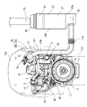
- FIG. 1st Embodiment It is a right view of the diesel engine which shows 1st Embodiment. It is the left side view. It is the same top view. It is the same rear view. It is right side section explanatory drawing of the exhaust-gas purification apparatus in 1st Embodiment. FIG. It is right side sectional explanatory drawing of the exhaust-gas purification apparatus which shows the 1st modification of a urea mixing pipe. FIG. It is right side sectional explanatory drawing of the exhaust-gas purification apparatus which shows the 2nd modification of a urea mixing pipe. FIG. It is a right view of the diesel engine which shows 2nd Embodiment. It is the same top view. It is the same rear view.
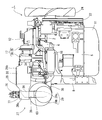
- FIG. 1 is a right side view in which an exhaust manifold 6 of a diesel engine 1 is installed
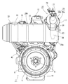
- FIG. 2 is a left side view in which an intake manifold 3 of the diesel engine 1 is installed
- FIG. 3 is a plan view in which a head cover 12 of the diesel engine 1 is installed.
- FIG. 4 and FIG. 4 are rear views in which the flywheel housing 8 of the diesel engine 1 is installed.
- the side on which the exhaust manifold 6 is installed is referred to as the right side of the diesel engine 1
- the side on which the intake manifold 3 is installed is referred to as the left side of the diesel engine 1
- the side on which the cooling fan 24 is installed is referred to as the diesel engine 1. It is called the front.
- An intake manifold 3 is disposed on one side surface of the cylinder head 2 of the diesel engine 1.
- the cylinder head 2 is mounted on a cylinder block 5 in which an engine output shaft 4 (crankshaft) and a piston (not shown) are built.
- An exhaust manifold 6 is disposed on the other side of the cylinder head 2. The front end and the rear end of the engine output shaft 4 are projected from the front and back of the cylinder block 5.
- the flywheel housing 8 is fixed to the back of the cylinder block 5.
- a flywheel 9 is provided in the flywheel housing 8.
- a flywheel 9 is pivotally supported on the rear end side of the engine output shaft 4.
- the power of the diesel engine 1 is taken out via the flywheel 9.
- an oil pan 11 is disposed on the lower surface of the cylinder block 5.
- a head cover 12 is disposed on the upper side surface of the cylinder head 2.
- an exhaust gas recirculation device (EGR) 15 for taking in exhaust gas for recirculation is arranged.
- An air cleaner (not shown) is connected to the intake manifold 3 via the compressor case 25 of the turbocharger 17.
- the external air that has been dust-removed and purified by the air cleaner is sent to the intake manifold 3 through the compressor case 25 and supplied to each cylinder of the diesel engine 1.
- a turbocharger 17 is disposed above the exhaust manifold 6.
- the turbocharger 17 includes a compressor case 25 with a built-in blower wheel and a turbine case 26 with a built-in turbine wheel.
- the exhaust intake side of the turbine case 26 is connected to the outlet of the exhaust manifold 6.
- the exhaust discharge side of the turbine case 26 is connected to the exhaust intake side of the exhaust gas purification device 27. That is, the exhaust gas discharged from each cylinder of the diesel engine 1 to the exhaust manifold 6 is released to the outside via the turbocharger 17 and the exhaust gas purification device 27.
- a cooling water pump 21 for circulating cooling water in the cylinder block 5 and the radiator 19 (see FIG. 16) is provided.
- a cooling water pump 21 is disposed on the side of the diesel engine 1 where the cooling fan 24 is installed.
- the cooling water pump 21 and the cooling fan 24 are connected to the engine output shaft 4 via the V belt 22 and the like, and the cooling water pump 21 and the cooling fan 24 are driven.
- the cooling water pump 21 is configured to send cooling water into the cylinder block 5 via the EGR cooler 18 of the exhaust gas recirculation device 15, while cooling the diesel engine 1 with cooling air from the cooling fan 24. Yes.
- a case 28 hereinafter referred to as a first case 28
- a second exhaust gas purification case 29 hereinafter referred to as a first exhaust gas purification case 29
- SCRF selective catalytic reduction filter
- an oxidation catalyst 30 is provided as an exhaust gas purifier.
- the oxidation catalyst 30 is, for example, a catalyst component (for example, Pt (platinum) or Pt) that promotes an oxidation reaction of carbon monoxide (CO) or hydrocarbon (HC) on a wall-through type ceramic honeycomb or metal mesh. Pd (palladium) or the like) is supported. Therefore, when the exhaust gas of the diesel engine 1 passes through the first case 28, carbon monoxide (CO) and hydrocarbons (HC) in the exhaust gas are reduced.
- an SCR filter 31 for urea selective catalyst reduction, an SCR catalyst 32 for urea selective catalyst reduction, and an ammonia slip catalyst (ASC) 33 are provided as exhaust gas purifiers. Is done.
- the SCR filter 31 is configured by applying an SCR catalyst component to a particulate matter (PM) collection filter.
- the SCR filter 31 has, for example, a structure in which a catalyst component (SCR catalyst component) that promotes selective catalytic reduction of NOx is supported on a wall flow ceramic honeycomb.
- the SCR catalyst 32 has a structure in which, for example, a SCR catalyst component is supported on a wall-through type ceramic honeycomb or a metal mesh.
- the ammonia slip catalyst 33 is an oxidation catalyst that oxidizes ammonia that has not reacted with the SCR filter 31 and the SCR catalyst 32. Therefore, when the exhaust gas of the diesel engine 1 passes through the second case 29, nitrogen oxides (NOx) in the exhaust gas are reduced.
- 1st case 28 is comprised in the elongate cylindrical shape extended long in parallel with the output shaft (crankshaft) 4 of the diesel engine 1 by planar view.
- the second case 29 is configured in a long cylindrical shape extending long in the orthogonal direction intersecting with the output shaft 4 of the diesel engine 1 in plan view. That is, the exhaust gas purifying device 27 is configured by arranging a long cylindrical first case 28 and a second case 29 in an L shape in a plan view so as to follow the outer periphery of the cylinder head 2 of the diesel engine 1. Has been placed.
- the first case 28 has an exhaust gas inlet side connected to an exhaust gas outlet of the turbine case 26 in the turbocharger 17 and a longitudinal middle portion connected to the cylinder head 2 via a case support bracket 34.
- the first case 28 is arranged on one straight line at substantially the same height as the turbocharger 17 on one side (right side) of the cylinder head 2. That is, the first case 28 and the turbocharger 17 are connected in series above the exhaust manifold 6. Therefore, even when the first case 28 of the exhaust gas purification device 27 is installed, the height of the diesel engine 1 can be kept low, and it can be installed even in an engine room with spatial limitations. .
- the second case 29 is fixed above the flywheel housing 8 via a case support bracket 35.
- the second case 29 is disposed at a position lower than the first case 28.
- the first case 28 and the second case 29 are L-shaped so that the exhaust gas downstream portion 28a of the first case 28 and the exhaust gas upstream portion 29a of the second case 29 are arranged in a vertically overlapping position.
- the first case 28 and the second case 29 are connected to each other by an exhaust communication pipe 36 at an exhaust gas downstream portion 28a and an exhaust gas upstream portion 29a that overlap each other.
- a urea water injector 76 that injects urea water into the first case 28 is fixed to an outer peripheral surface of the first case 28 that overlaps the second case 29 in a plan view and is different from the installation position of the exhaust communication pipe 36. Has been.
- the first case 28 is supported on the exhaust manifold 6 side surface (right side surface) of the diesel engine 1 with high rigidity by the turbocharger 17 and the case support bracket 34, while the second case 29 is supported by the first case 28 and the case support.
- the bracket 35 is supported on the flywheel housing 8 side surface (back surface) of the diesel engine 1 with high rigidity. Therefore, the exhaust gas purification device 27 can be supported with high rigidity in the space above the exhaust manifold 6 and the flywheel housing 8 at the outer peripheral position of the cylinder head 2, and at the same time, the diesel engine 1 having the exhaust gas purification device 27. Can be configured compactly.
- the first case 28 has a shape contracted toward the exhaust gas downstream side so that the cross section of the exhaust gas downstream portion 28a is smaller than the cross section of the exhaust gas purifying body installation portion 28b.
- the exhaust gas downstream portion 28a is provided inside the exhaust gas purifying body installation portion 28b.
- the second case 29 has a shape contracted toward the exhaust gas upstream side so that the cross section of the exhaust gas upstream portion 29a is smaller than the cross section of the exhaust gas purifying bodies 31 to 33 installation portion 29b.
- the exhaust gas downstream portion 28a is provided at a position where the lower ends of the exhaust gas purifying body installation portions 28b are at the same height.
- the urea mixing pipe 39 provided in the exhaust communication pipe 36 that connects the exhaust gas downstream part 28a and the exhaust gas upstream part 29a has a length capable of sufficiently mixing the urea water and the exhaust gas.
- a fuel pump 42 and a common rail 43 for connecting a fuel tank 45 shown in FIG. 15 (FIG. 16) are provided to each injector (not shown) for multiple cylinders of the diesel engine 1.
- a common rail 43 and a fuel filter 44 are disposed on the intake manifold 3 installation side of the cylinder head 2, and a fuel pump 42 is disposed on the cylinder block 5 below the intake manifold 3.
- Each injector has an electromagnetic switching control type fuel injection valve (not shown).
- the common rail 43 is connected to the discharge side of the fuel pump 42, and the cylindrical common rail 43 is connected to each injector of the diesel engine 1.
- the surplus of the fuel pumped from the fuel pump 42 to the common rail 43 is returned to the fuel tank 45, high-pressure fuel is temporarily stored in the common rail 43, and the high-pressure fuel in the common rail 43 is used for each diesel engine 1. Supplied inside the cylinder.
- the fuel in the fuel tank 45 is pumped to the common rail 43 by the fuel pump 42, the high-pressure fuel is stored in the common rail 43, and the fuel injection valves of the injectors are controlled to open and close.
- the high-pressure fuel in 43 is injected into each cylinder of the diesel engine 1. That is, by electronically controlling the fuel injection valve of each injector, the fuel injection pressure, injection timing, and injection period (injection amount) can be controlled with high accuracy. Therefore, nitrogen oxides (NOx) discharged from the diesel engine 1 can be reduced.
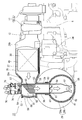
- the exhaust gas purifying device 27 includes a first case 28 having a double tube structure including a first inner case 37 and a first outer case 38, a second inner case 40 and a second outer case.
- the second case 29 having a double pipe structure 41 is connected by an exhaust communication pipe 36.
- the oxidation catalyst 30 is provided in a first cylindrical inner case 37 made of a heat resistant metal material, and the first inner case 37 is provided in a first outer case 38 made of a heat resistant metal material and substantially cylindrical.
- the SCR filter 31, the SCR catalyst 32, and the ammonia slip catalyst 33 are provided in a substantially cylindrical second inner case 40 made of a refractory metal material, and the second inner case 40 is made of a refractory metal material and is substantially cylindrical.
- the second outer case 41 is provided.
- the first inner case 37 is fitted on the outside of the oxidation catalyst 30 serving as the first exhaust gas purifier through a mat-like heat insulating material 49 made of ceramic fiber. ing. That is, the heat insulating material 49 is pressed between the oxidation catalyst 30 and the first inner case 37 to protect the oxidation catalyst 30. Further, a ring-shaped spacer (not shown) is fitted between the first outer case 38 and the first inner case 37 so that the outer peripheral surface of the first inner case 37 and the first outer case 38 are It is fitted on the outer side of the first inner case 37 so as to be separated from the inner peripheral surface.
- the second case 29 has ceramic fiber-made mat-like heat insulating materials 50 to 52 outside the SCR filter 31, the SCR catalyst 32, and the ammonia slip catalyst 33 that are the second exhaust gas purifiers.
- the second inner case 40 is fitted. That is, the heat insulating materials 50 to 52 are press-fitted between the SCR filter 31, the SCR catalyst 32 and the ammonia slip catalyst 33 and the second inner case 40 to protect the SCR filter 31, the SCR catalyst 32 and the ammonia slip catalyst 33.
- the second outer case 41 has a ring-shaped spacer (not shown) fitted between the second inner case 40 and the outer peripheral surface of the second inner case 40 and the second outer case 41. It is fitted on the outer side of the second inner case 40 so as to be separated from the inner peripheral surface.
- the first case 28 has an exhaust gas downstream portion 28 a on the downstream side of the exhaust gas from the oxidation catalyst 30 and is shorter than the exhaust gas purifier installation portion 28 b where the oxidation catalyst 30 is installed. Consists of diameter. That is, in both the first inner case 37 and the first outer case 38, the exhaust gas downstream portion 28a has a shorter diameter than the exhaust gas purifier installation portion 28b. Further, in the first inner case 37 and the first outer case 38, through holes 53 to 56 are provided vertically in the exhaust gas downstream portion 28a.
- an injector installation case 57 to which the urea water injector 76 is fixed is inserted.
- the ejector installation case 57 has a first outer case 37 and a first outer case 38 so that the outer peripheral surfaces thereof are in contact with the inner peripheral edges of the through holes 53 and 54 of the first inner case 37 and the first outer case 38. It is fixed above the exhaust gas downstream portion 28a. Thereby, urea water from the urea water injection body 76 can be guided into the first inner case 37, and urea water and exhaust gas enter the space between the first inner case 37 and the first outer case 38. Can be prevented.
- the urea mixing pipe 39 is inserted into the through hole 55 of the first inner case 37, and the exhaust communication pipe covering the outer periphery of the urea mixing pipe 39 together with the urea mixing pipe 39 is inserted into the through hole 56 of the first outer case 38.
- 36 is inserted.
- the exhaust communication pipe 36 has a front end portion on the exhaust gas upstream side which is the outer peripheral surface of the first inner case 37 and abuts the outer portion of the through hole 55, and the outer peripheral surface thereof is the through hole 56 of the first outer case 38.
- the first inner case 37 and the first outer case 38 are fixed below the exhaust gas downstream portion 28a so as to be in contact with the inner peripheral edge.
- the urea mixing tube 39 is fixed so that the outer peripheral surface thereof is in contact with the inner peripheral edge of the through hole 55 of the first inner case 37, and the distal end portion of the exhaust gas upstream side is inserted up to the injector installation case 57. Is done. Thereby, while being able to make the connection part of the 1st case 28 and the 2nd case 29 into a double pipe structure with high heat insulation, in the space between the 1st inner case 37 and the 1st outer case 38, It is possible to prevent urea water and exhaust gas from entering.
- a disc-shaped exhaust outlet side inner lid body 58 is fixed to the exhaust outlet side end portions of the first inner case 37 and the first outer case 38, and the exhaust outlet side outer lid 58 is attached to the outer surface side of the exhaust outlet side inner lid body 58.
- a lid 59 is fixed.
- the exhaust gas downstream end face of the oxidation catalyst 30 and the exhaust outlet side inner lid body 58 are separated from each other by a certain distance, and the oxidation catalyst 30 and the exhaust outlet are disposed inside the first inner case 37 in the exhaust gas downstream portion 28a.
- an upstream side urea mixing chamber 60 into which the urea mixing pipe 39 is inserted from the outside is configured.
- the second case 29 has an exhaust gas upstream portion 29 a on the exhaust gas upstream side of the SCR filter 31, and an exhaust gas in which the SCR filter 31, the SCR catalyst 32 and the ammonia slip catalyst 33 are installed. It has a shorter diameter than the gas purification body installation portion 29b. That is, in both the second inner case 40 and the second outer case 41, the exhaust gas upstream portion 29a has a shorter diameter than the exhaust gas purifier installation portion 29b. Further, the second inner case 40 and the second outer case 41 are provided with through holes 61 and 62 above the exhaust gas upstream portion 29a.
- An exhaust inlet pipe 63 is provided on the outer peripheral surface of the second inner case 40, covers the through hole 61 on the exhaust outlet side of the exhaust inlet pipe 63, and the exhaust inlet side of the exhaust inlet pipe 63 is connected to the second outer case 41. It protrudes outward from the through hole 62.
- the urea mixing pipe 39 is inserted into the through hole 61 of the second inner case 40, and the exhaust communication pipe 36 covering the outer periphery of the urea mixing pipe 39 is inserted into the exhaust inlet pipe 63 together with the urea mixing pipe 39.
- the exhaust communication pipe 36 has a front end portion on the exhaust gas upstream side which is the outer peripheral surface of the second inner case 40 and abuts the outer portion of the through hole 61, and the outer peripheral surface thereof is an exhaust inlet portion of the exhaust inlet pipe 63.
- the second inner case 40 and the second outer case 41 are fixed above the exhaust gas upstream portion 29a so as to be in contact with the inner peripheral edge.
- the urea mixing tube 39 is fixed so that the outer peripheral surface thereof is in contact with the inner peripheral edge of the through hole 61 of the second inner case 40, and the distal end portion of the exhaust gas downstream side is inserted into the second inner case 40. Is done. Thereby, while being able to make the connection part of the 1st case 28 and the 2nd case 29 into a double tube structure with high heat insulation, in the space between the 2nd inner case 40 and the 2nd outer case 41, It is possible to prevent urea water and exhaust gas from entering.
- a disc-shaped exhaust inlet side inner lid body 64 is fixed to the exhaust inlet side end portions of the second inner case 40 and the second outer case 41, and the exhaust inlet side outer lid 64 is disposed outside the exhaust inlet side inner lid body 64.
- a lid 65 is fixed.
- the exhaust gas upstream end face of the SCR filter 31 and the SCR filter 31 are separated by a certain distance, and the SCR filter 31 and the exhaust inlet side inner lid body are disposed inside the second inner case 40 in the exhaust gas upstream portion 29a.
- a downstream urea mixing chamber 66 into which the urea mixing pipe 39 is inserted from the outside is configured.
- a urea water injector 76 is attached to an injector installation case 57 provided in the exhaust gas downstream portion 28a via an injection base 77.
- the urea water ejector 76 sprays the urea aqueous solution into the upstream urea mixing chamber 60 in the first inner case 37.
- a urea water injection valve 78 protruding downward is inserted into a nozzle installation hole 79 provided in the injection base 77.
- the injector installation hole 79 is provided so that the position of the nozzle installation hole 79 provided through the urea solution injector 76 coincides with the position of the urea solution guide hole 80 provided through the injector installation case 57.
- the urea water injector 76 is installed on the case 57. Therefore, the urea water injected from the urea water injection valve 78 of the urea water injection body 76 passes through the nozzle installation hole 79 and the urea water guide hole 80 and passes through the urea mixing tube 39 inserted into the upstream urea mixing chamber 60. Induced inside.
- the urea mixing pipe 39 has a mixing pipe inlet 81 on the upper end side inserted into the upstream urea mixing chamber 60 configured on the exhaust outlet side of the first case 28,
- the mixing tube outlet 82 on the lower end side is inserted into the downstream urea mixing chamber 66 configured on the exhaust inlet side of the second case 29.
- the urea mixing pipe 39 is covered with an exhaust communication pipe 36 connected to the first and second cases 28, 29 at the midway outer peripheral surface between the first case 28 and the second case 29.
- the urea mixing pipe 39 is covered with the first and second cases 28 and 29 and the exhaust communication pipe 36 so that a heat insulating layer is provided on the outer peripheral surface thereof. Therefore, since the inside of the urea mixing tube 39 can be maintained at a high temperature, the formation of crystal lumps due to the urea component in the urea mixing tube 39 can be suppressed.
- the urea mixing pipe 39 has a shape in which an end portion serving as the mixing pipe inlet 81 is obliquely cut (obliquely cut cylindrical shape), from the pipe wall near the oxidation catalyst 30 toward the pipe wall near the exhaust outlet side inner lid body 58. It is low. That is, the mixing pipe inlet 81 of the urea mixing pipe 39 closes the oxidation catalyst 30 side by bringing the pipe wall near the oxidation catalyst 30 into contact with the outer portion of the urea water guide hole 80 on the inner peripheral surface of the injector installation case 57. On the other hand, it opens toward the exhaust outlet side inner lid body 58.
- the inner peripheral surface of the mixing tube inlet 81 of the urea mixing tube 39 is disposed on the outer peripheral side of the urea water guide hole 80 of the injector installation case 57.
- the portion of the tube wall inserted into the first case 28 has a porous shape provided with a plurality of exhaust introduction holes 83.
- the mixing tube inlet 81 of the urea mixing tube 39 has a shape in which the tube wall becomes higher toward the oxidation catalyst 30, most of the exhaust gas that has passed through the oxidation catalyst 30 flows from the exhaust outlet side inner lid body 58. Thus, it is introduced into the urea mixing tube 81. Therefore, each of the obliquely cut opening and the exhaust introduction hole 83 at the mixing pipe inlet 81 functions as an exhaust introduction port into the urea mixing pipe 39, so that the flow velocity of the exhaust gas introduced into the urea mixing pipe 39 is obtained. Can be made uniform.
- the urea water injected from the urea water injection valve 78 toward the mixing pipe inlet 81 in the urea mixing pipe 39 is easily stirred and dispersed, improving the evaporability of the urea component at a low temperature, and the exhaust gas.
- the reaction efficiency with the urea component can be increased.
- the urea mixing tube 39 has a shape (a tapered shape) in which an end portion serving as the mixing tube outlet 82 is narrowed toward the tip, and the diameter of the mixing tube outlet 82 is shortened toward the tip.
- a mixing tube outlet 82 is extended toward the inner wall surface on the opposite side to the exhaust inlet tube 63.
- the mixing tube outlet 82 of the urea mixing tube 39 extends in the second inner case 40 of the second case 29, it is disposed at a position separated from the inner wall surface of the second inner case 40.
- the mixing tube outlet 82 of the urea mixing tube 39 has a shape provided with a throttle at the tip, urea water collides with the inner wall surface at the tip of the mixing tube outlet 82. Therefore, the reaction between the exhaust gas and the urea component in the downstream urea mixing chamber 66 of the second case 29 is promoted by evaporating the exhaust gas and the unreacted urea component by collision with the mixing tube outlet 82. Moreover, the urea component can be prevented from reaching the inner wall surface of the second inner case 40, and the formation of crystal lumps on the inner wall surface of the second inner case 40 can be suppressed.
- the urea mixing tube 39 includes a mixer 84 that promotes mixing of urea water and exhaust gas downstream from the position where the exhaust introduction hole 83 is formed.
- the mixer 84 is configured by, for example, providing a plurality of blades radially so as to be point-symmetric with respect to the central axis of the urea mixing tube 39, and disperse and agitate urea water in the exhaust gas.
- the mixer 84 is installed at a portion where the urea mixing pipe 39 is inserted into the second case 29 (near the installation position of the through holes 61 and 62), and upstream of the mixing pipe outlet 82 in the urea mixing pipe 39. It is fixed.
- the mixer 84 is disposed in the second case 29 having a high heat insulating property, the temperature drop of the mixer 84 can be suppressed. Further, since the exhaust gas having a uniform flow velocity at the mixing pipe inlet 81 flows into the mixer 84, there is no variation in the swirlability in the mixer 84, so that urea water is easily mixed with the exhaust gas, and the urea component is evaporated. Can be improved. Accordingly, not only the urea component crystallization in the mixer 84 can be prevented, but also the reaction between the exhaust gas and the urea component can be promoted, and the droplet-like urea water can be prevented from entering the second case 29.
- the mixing tube outlet 82 on the downstream side of the mixer 84 has a tapered shape, the droplet-shaped urea water that has passed through the mixer 84 collides with the mixing tube outlet 82, so that the inside of the second inner case 40. This prevents the urea component from reaching the wall.
- the shape of the mixing tube inlet 81 of the urea mixing tube 39 is a bell mouth shape, and the tip periphery thereof is widened, so that the urea of the injector installation case 57 It is made to contact
- a part of the tube wall at the portion where the urea mixing tube 39 is inserted into the first case 28 is bent inside the urea mixing tube 39, and the bent tube wall is configured as the urea collision plate 85. .
- an opening portion formed by cutting out the urea collision plate 85 in the tube wall of the urea mixing tube 39 serves as an exhaust introduction port 86 for introducing the exhaust gas that has passed through the oxidation catalyst 30 into the urea mixing tube 39. Composed.
- the urea mixing tube 39 is provided with a plurality of urea collision plates 85 with a part of the tube wall bent, and the urea collision plate 85 is on the center side of the urea mixing tube 39 and away from the urea water injection valve 78. It is extended toward.
- the urea mixing tube 39 includes an exhaust introduction port 86 that opens downward from the bent position of the urea collision plate 85, and has a narrowed (squeezed) shape where the installation portion of the urea collision plate 85 has a short diameter.
- the urea mixing tube 39 has a shape in which the cross-sectional area is continuously expanded from the installation portion of the urea collision plate 85 toward the downstream side (lower side).
- the mixing tube inlet 81 of the urea mixing tube 39 By making the mixing tube inlet 81 of the urea mixing tube 39 into a bell mouth shape, the urea component from the urea water injection valve 78 is difficult to adhere to the tube wall of the urea mixing tube 39.
- the flow rate of the exhaust gas introduced from the exhaust introduction port 86 can be increased by providing a throttle at the installation portion of the exhaust introduction port 86, The temperature increase of the tube wall of the urea mixing tube 39 can be promoted.
- the temperature drop of the tube wall of the urea mixing tube 39 can be suppressed by gradually expanding the tube wall of the urea mixing tube 39 toward the lower through holes 55 and 56 of the first case 28.
- the urea mixing pipe 39 has the urea collision plate 85 disposed on the downstream side (lower side) of the urea water injection valve 78, the urea water injected from the urea water injection valve 78 collides with the urea collision plate 85, and It promotes the atomization of urea water and promotes the reaction between urea components and exhaust gas.
- the urea collision plate 85 increases the inclination angle (urea water collision angle) with respect to the injection direction of the urea water from the urea water injection valve 78, so that the urea water to the pipe wall constituting the urea collision plate 85 is increased. It becomes difficult to form a liquid film, and the formation of crystal lumps due to the urea component can be suppressed.
- the urea collision plate 85 by forming the urea collision plate 85 by a part of the tube wall in the urea mixing pipe 39 and simultaneously providing the exhaust introduction port 86, the urea collision plate 85 is exposed to high-temperature exhaust gas, and the urea collision plate 85 is The temperature can be raised. Therefore, even if the urea water injected from the urea water injection valve 78 collides with the urea collision plate 85, the urea collision plate 85 can suppress the formation of crystal lumps due to the urea component.
- a throttle is provided on the downstream side of the mixing pipe inlet 81, and the urea collision plate 85 is disposed at the throttle position.
- FIG. 11 is a right side view in which the exhaust manifold 6 of the diesel engine 1 is installed
- FIG. 12 is a plan view in which the head cover 12 of the diesel engine 1 is installed
- FIG. 13 is a rear view in which the flywheel housing 8 of the diesel engine 1 is installed.
- FIG. in the engine device of the present embodiment the same parts and portions as those of the engine device of the first embodiment are denoted by the same reference numerals, and detailed description thereof is omitted.
- the exhaust gas purifying device 27 of the present embodiment injects urea water at a position on the inner peripheral side (closer to the head cover 12) than the upper end on the outer peripheral surface of the exhaust gas downstream portion 28a of the first case 28.
- the body 76 is fixed.
- the first inner case 37 and the first outer case 38 of the first case 28 are provided with through holes 54 and 55 at positions on the left side of the exhaust gas downstream portion 28a (closer to the head cover 12) than the upper end.
- the injector installation case 57 is installed so as to be skewed to the lower right side with respect to the through holes 54 and 55 provided in the first case 28.
- the installation surface of the urea water injector 76 in the injector installation case 57 becomes a surface inclined to the head cover 12 side (left side), and the urea water injector 76 is inclined and installed. Accordingly, the urea water injector 76 is supported at a low position on the upper surface of the diesel engine 1, and the height on the upper surface side of the diesel engine 1 can be formed low.
- the urea mixing pipe 39 is inserted into the first case 28 from the lower side of the first case 28 and from the outer side (right side), and the mixing pipe inlet 81 faces the urea water ejector 76 (upper left side). Is extended). That is, the urea mixing tube 39 is inserted into the first inner case 37 through the through holes 55 and 56 provided on the outer side (right side) of the machine tube inlet 81 below the first case 28. Is done.
- the urea mixing tube 39 has a middle portion bent in the second case 29, and a mixing tube outlet 82 is inserted into the second case 29 so as to be orthogonal to the longitudinal direction of the second case 29. .
- the exhaust communication pipe 36 is inclined so as to incline from the direction perpendicular to the longitudinal direction of the second case 29 (vertical direction) to the cylinder head 2 side (left side).
- the exhaust communication pipe 36 communicates with the exhaust inlet pipe 63 projecting from the second outer case 41 and the through hole 56 of the first outer case 38 and covers the middle outer peripheral surface of the urea mixing pipe 39. Yes. Further, a bent portion of the urea mixing pipe 39 is provided in the vicinity of the through holes 61 and 62 of the second case 29 and is covered with the exhaust communication pipe 36 and the exhaust inlet pipe 63.
- the pipe wall of the bent portion can be heated to a high temperature, so that crystallization due to the urea component colliding with the inner wall surface of the exhaust communication pipe 36 can be suppressed. .
- a mixer 84 is installed at a portion where the urea mixing tube 39 is inserted into the first case 28.
- the urea mixing pipe 39 includes a mixer 84 that promotes mixing of urea water and exhaust gas downstream from the position where the exhaust introduction hole 83 is formed.
- the mixer 84 is installed in the vicinity of the installation position of the lower through holes 55 and 56 of the first case 28.
- the mixer 84 since the mixer 84 is installed in the first case 28, the distance from the mixer 84 to the mixing tube outlet 82 in the urea mixing tube 39 becomes longer. The exhaust gas in which the components are sufficiently mixed and stirred is discharged. For this reason, in the above configuration, the mixing tube outlet 82 of the urea mixing tube 39 inserted into the second case 29 has a constricted throttle, as in the first embodiment.
- the pipe diameter may be the same diameter up to the tip.
- the shape of the urea mixing pipe 39 on the side of the mixing pipe inlet 81 may be configured as in the first modification, or as in the second modification.
- the heat exchange fins 87 may be provided on the mixing tube outlet 82 side of the urea mixing tube 39.
- the backhoe 100 includes a crawler-type traveling device 102 having a pair of left and right traveling crawlers 103, and a turning machine body 104 provided on the traveling device 102.
- the revolving machine body 104 is configured to be horizontally revolved over 360 ° in all directions by a revolving hydraulic motor (not shown).
- a cabin (control unit) 106 is mounted on the front left side of the revolving machine body 104.
- a working unit 110 having a boom 111 and a bucket 113 for excavation work is provided at the front center portion of the revolving machine body 104.
- the radiator 19 and the diesel engine 1 are mounted on the rear portion of the revolving machine body 104.
- a fuel tank 45 and a urea water tank 71 are mounted on the right side of the revolving machine body 104.
- the cabin 106 is provided with a control seat on which an operator is seated, operating means for operating the diesel engine 1 and the like, and levers or switches as operating means for the working unit 110.
- a boom cylinder 112 and a bucket cylinder 114 are arranged on a boom 111 which is a component of the working unit 110.
- a bucket 113 as an attachment for excavation is pivotally attached to the tip end portion of the boom 111 so as to be inserted and rotated.
- the boom cylinder 112 or the bucket cylinder 114 is operated to perform earthwork work (ground work such as grooving) by the bucket 113.
- the radiator 19 is installed on the left rear side of the revolving machine body 104, and the diesel engine 1 is installed on the right side of the radiator 19 so that the cooling fan 24 faces the radiator 19.
- the diesel engine 1 is installed such that the installation surface of the exhaust manifold 6 faces the cabin 106 and the working unit 110, and the upper surface thereof is covered with a bonnet 115.
- the first case 28 of the exhaust gas purification device 27 is disposed behind the working unit 110, and the second case 29 is disposed so as to extend rearward from a connection portion with the first case 28. .
- a tail pipe 116 connected to the exhaust outlet of the second case 29 projects upward from the rear of the bonnet 115.
- the fuel tank 45 and the urea water tank 71 are arranged forward and backward on the right side of the revolving machine body 104, and the oil inlet 46 of the fuel tank 45 and the water inlet 72 of the urea water tank 71 are provided so as to protrude rightward. ing. Further, a urea water injection pump 73 that pumps the urea aqueous solution in the urea water tank 71 is installed at a position between the urea water tank 71 and the first case 28.
- the urea water pipe connecting the urea water injector 76 fixed to the first case 28 and the urea water pump 73 can be shortened, and at the same time, the urea water connecting the urea water tank 71 and the urea water pump 73.
- the piping can also be shortened.
- the diesel engine 1 of the present embodiment has a configuration in which the first case 28 of the exhaust gas purifying device 27 is provided on the upper surface of the diesel engine 1 and the second case 29 is remotely arranged as shown in FIG.
- the exhaust outlet of the first case 28 and the exhaust outlet of the second case 29 are communicated by an L-shaped exhaust connecting pipe 177 and the exhaust connecting pipe 177 includes a urea mixing pipe 176 so that the first case The connection part of 28 and the 2nd case 29 is made into the double tube structure.
- the urea mixing pipe 176 includes a mixing pipe inlet 81 inserted into the exhaust gas downstream portion 28a of the first case 28, as in the second embodiment.
- the configuration of the urea mixing tube 176 on the mixing tube inlet 81 side is configured such that the end portion thereof is obliquely cut and has an exhaust introduction hole 83 and a mixer 84 is incorporated (see FIG. 16). ).
- the urea mixing tube 176 includes a mixing tube outlet 82 inserted into the exhaust gas upstream portion 29a of the second case 29, as in the second embodiment.
- the configuration of the urea mixing tube 176 on the mixing tube inlet 81 side is a configuration in which a throttle is provided at the tip, as in the second embodiment.
- the urea mixing tube 176 may be the one to which the configuration according to the first and second modified examples described above is applied, as in the first and second embodiments.
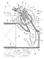
- a tractor 151 equipped with the diesel engine 1 according to the third embodiment will be described with reference to FIGS.
- a farm tractor 151 as a work vehicle supports a traveling machine body 152 with a pair of left and right front wheels 153 and a pair of left and right rear wheels 154, and the diesel engine is mounted on the front of the traveling machine body 152.
- the engine 1 is mounted, and the diesel engine 1 drives the rear wheel 154 and the front wheel 153 so as to travel forward and backward.
- the upper surface side and the left and right side surfaces of the diesel engine 1 are covered with a hood 156 that can be opened and closed.
- a cabin (manipulation unit) 157 on which an operator is boarded is installed behind the hood 156.
- a steering seat 158 on which an operator is seated and steering equipment such as a steering handle 159 as steering means are provided inside the cabin 157.
- a pair of left and right steps 160 for the operator to get on and off are provided on the left and right outer portions of the cabin 157, and fuel is supplied to the diesel engine 1 inside the step 160 and below the bottom portion of the cabin 157.
- a fuel tank 45 to be supplied is provided.
- the traveling machine body 152 includes a transmission case 161 for shifting the output from the diesel engine 1 and transmitting it to the rear wheel 154 (front wheel 153).
- a tiller and the like (not shown) are connected to the rear portion of the mission case 161 via a lower link 162, a top link 163, a lift arm 164, and the like so as to be movable up and down.
- a PTO shaft 165 for driving the tillage working machine and the like is provided on the rear side surface of the mission case 161.
- the traveling machine body 152 of the tractor 151 includes the diesel engine 1, a transmission case 161, a clutch case 166 that connects them, and the like.
- the second case 29 is erected so as to be vertically arranged at the right corner of the cabin 157 in the front surface of the cabin 157, and the tail pipe 178 is erected from the exhaust outlet side of the second case 29. . That is, the tail pipe 178 and the second case 29 are vertically arranged in series on the front surface of the right corner of the cabin 157.
- the exhaust inlet pipe 63 of the second case 29 is connected to the exhaust outlet of the first case 28 inside the bonnet 156 via an exhaust connecting pipe 177 having a bellows-shaped flexible pipe 179 in the middle.
- a urea water tank 71 is installed on the left side of the bonnet 156 opposite to the right side where the tail pipe 178 is arranged, in the front surface of the cabin 157. That is, the urea water tank 71 is mounted on the traveling machine body 152 (such as the bottom frame of the cabin 157) on the rear left side of the hood 156. An oil inlet 46 of the fuel tank 45 and a water inlet 72 of the urea water tank 71 are provided adjacent to each other at the lower front portion on the left side of the cabin 157.
- the tail pipe 178 is disposed on the front surface on the right side of the cabin 157 where the operator's boarding / alighting frequency is low, while the oil inlet 46 and the water inlet 72 are disposed on the front surface on the left side of the cabin 157 where the operator's boarding / alighting frequency is high.
- the cabin 157 is configured so that the operator can get on and off the control seat 158 from either the left side or the right side.
- a urea water injection pump 73 that pumps the urea aqueous solution in the urea water tank 71 is installed at a position between the urea water tank 71 and the first case 28.
- the urea water piping connecting the urea water injection body 76 fixed to the first case 28 and the urea water injection pump 73 can be shortened, and at the same time, the urea water tank 71 and the urea water injection pump 73 are connected.
- the urea water piping can also be shortened.
- the urea water piping can be efficiently piped, so that not only the trouble in piping work and maintenance work can be eliminated, but also the influence of the external environment in the urea water piping can be reduced, and the urea water crystallization in the urea water pipe can be reduced. Can be suppressed.
- a DPF case including an oxidation catalyst and a soot filter as a first exhaust gas purifier is a first case
- an SCR catalyst and an ammonia slip catalyst are used as a second exhaust gas purifier. It may be applied to an exhaust gas processing apparatus in which an SCR case provided with a second case is used. Further, although the blades are also fixed for the mixer, the blades may be rotated.
Landscapes
- Engineering & Computer Science (AREA)
- Chemical & Material Sciences (AREA)
- Chemical Kinetics & Catalysis (AREA)
- Combustion & Propulsion (AREA)
- Mechanical Engineering (AREA)
- General Engineering & Computer Science (AREA)
- Health & Medical Sciences (AREA)
- Toxicology (AREA)
- Exhaust Gas After Treatment (AREA)
Abstract
Priority Applications (8)
| Application Number | Priority Date | Filing Date | Title |
|---|---|---|---|
| US15/999,653 US10690034B2 (en) | 2016-02-19 | 2017-02-15 | Engine device |
| EP17753251.2A EP3418521B1 (fr) | 2016-02-19 | 2017-02-15 | Dispositif de moteur |
| EP21167164.9A EP3936705A1 (fr) | 2016-02-19 | 2017-02-15 | Dispositif de moteur |
| CN201780005783.4A CN109072753B (zh) | 2016-02-19 | 2017-02-15 | 发动机装置 |
| KR1020187011914A KR102011611B1 (ko) | 2016-02-19 | 2017-02-15 | 엔진 장치 |
| US16/901,122 US11092056B2 (en) | 2016-02-19 | 2020-06-15 | Engine device |
| US17/376,107 US11643960B2 (en) | 2016-02-19 | 2021-07-14 | Engine device |
| US18/125,128 US20230228208A1 (en) | 2016-02-19 | 2023-03-23 | Engine Device |
Applications Claiming Priority (4)
| Application Number | Priority Date | Filing Date | Title |
|---|---|---|---|
| JP2016030017A JP6430976B2 (ja) | 2016-02-19 | 2016-02-19 | エンジン装置 |
| JP2016-030016 | 2016-02-19 | ||
| JP2016030016A JP6430975B2 (ja) | 2016-02-19 | 2016-02-19 | エンジン装置 |
| JP2016-030017 | 2016-02-19 |
Related Child Applications (3)
| Application Number | Title | Priority Date | Filing Date |
|---|---|---|---|
| EP21167164.9A Previously-Filed-Application EP3936705A1 (fr) | 2016-02-19 | 2017-02-15 | Dispositif de moteur |
| US15/999,653 A-371-Of-International US10690034B2 (en) | 2016-02-19 | 2017-02-15 | Engine device |
| US16/901,122 Continuation US11092056B2 (en) | 2016-02-19 | 2020-06-15 | Engine device |
Publications (1)
| Publication Number | Publication Date |
|---|---|
| WO2017141995A1 true WO2017141995A1 (fr) | 2017-08-24 |
Family
ID=59625178
Family Applications (1)
| Application Number | Title | Priority Date | Filing Date |
|---|---|---|---|
| PCT/JP2017/005597 WO2017141995A1 (fr) | 2016-02-19 | 2017-02-15 | Dispositif de moteur |
Country Status (5)
| Country | Link |
|---|---|
| US (4) | US10690034B2 (fr) |
| EP (2) | EP3418521B1 (fr) |
| KR (1) | KR102011611B1 (fr) |
| CN (2) | CN112855310A (fr) |
| WO (1) | WO2017141995A1 (fr) |
Cited By (2)
| Publication number | Priority date | Publication date | Assignee | Title |
|---|---|---|---|---|
| CN110894804A (zh) * | 2019-11-29 | 2020-03-20 | 安徽中鼎流体系统有限公司 | 一种汽车尾气排气系统scr机械管路总成 |
| CN112746886A (zh) * | 2021-01-19 | 2021-05-04 | 武汉洛特福动力技术有限公司 | U型结构带混合器的汽车尾气净化装置 |
Families Citing this family (4)
| Publication number | Priority date | Publication date | Assignee | Title |
|---|---|---|---|---|
| EP3418521B1 (fr) * | 2016-02-19 | 2021-04-21 | Yanmar Power Technology Co., Ltd. | Dispositif de moteur |
| CN215486219U (zh) * | 2021-08-26 | 2022-01-11 | 佛吉亚排气控制技术开发(上海)有限公司 | 混合器、废气处理部件、废气后处理系统及运载工具 |
| US11732629B1 (en) | 2022-05-10 | 2023-08-22 | Caterpillar Inc. | System, apparatus, and method for diesel exhaust fluid (DEF) dosing |
| CN115807707A (zh) * | 2023-01-09 | 2023-03-17 | 北方稀土华凯高科技河北有限公司 | 一种用于柴油机尿素喷射混合的旋流盖混合器 |
Citations (6)
| Publication number | Priority date | Publication date | Assignee | Title |
|---|---|---|---|---|
| JPS5244334B2 (fr) | 1973-05-28 | 1977-11-07 | ||
| JPS5543563B2 (fr) | 1974-03-29 | 1980-11-07 | ||
| JP2010090788A (ja) * | 2008-10-07 | 2010-04-22 | Yanmar Co Ltd | 野菜収穫機 |
| JP2010101236A (ja) * | 2008-10-23 | 2010-05-06 | Mitsubishi Fuso Truck & Bus Corp | 内燃機関の排気浄化装置 |
| JP2011099415A (ja) * | 2009-11-09 | 2011-05-19 | Mitsubishi Fuso Truck & Bus Corp | エンジンの排気浄化装置 |
| JP2015148224A (ja) * | 2014-02-10 | 2015-08-20 | トヨタ自動車株式会社 | 内燃機関の排気浄化装置 |
Family Cites Families (24)
| Publication number | Priority date | Publication date | Assignee | Title |
|---|---|---|---|---|
| JPS5244334A (en) | 1975-10-07 | 1977-04-07 | Toyota Motor Corp | Throttle valve control device with a evapo-system |
| JPS5543563A (en) | 1978-09-22 | 1980-03-27 | Ricoh Co Ltd | Developing apparatus |
| US7328572B2 (en) * | 2006-02-23 | 2008-02-12 | Fleetguard, Inc. | Exhaust aftertreatment device with star-plugged turbulator |
| US7998423B2 (en) * | 2007-02-27 | 2011-08-16 | Basf Corporation | SCR on low thermal mass filter substrates |
| US7748212B2 (en) * | 2007-03-09 | 2010-07-06 | Cummins Filtration Ip, Inc. | Exhaust aftertreatment system with flow distribution |
| JP5244334B2 (ja) * | 2007-05-01 | 2013-07-24 | 三菱ふそうトラック・バス株式会社 | 内燃機関の排気浄化装置 |
| JP2011241705A (ja) * | 2010-05-17 | 2011-12-01 | Toyota Industries Corp | 排気ガス浄化装置 |
| JP5490739B2 (ja) * | 2011-02-25 | 2014-05-14 | 日立建機株式会社 | 建設機械 |
| JP2012219624A (ja) * | 2011-04-04 | 2012-11-12 | Hitachi Constr Mach Co Ltd | 建設機械 |
| US9267413B2 (en) * | 2012-06-20 | 2016-02-23 | Cnh Industrial America Llc | Exhaust system for an agricultural vehicle |
| KR20140023696A (ko) * | 2012-08-17 | 2014-02-27 | 세종공업 주식회사 | 디젤 엔진의 배기가스 후처리 시스템 |
| KR101439120B1 (ko) * | 2012-08-23 | 2014-09-11 | 대동공업주식회사 | 농업용 작업차량의 배기가스 후처리장치 취부구조 |
| JP5543563B2 (ja) | 2012-10-16 | 2014-07-09 | 株式会社小松製作所 | 排気処理ユニット |
| JP5536844B2 (ja) * | 2012-10-16 | 2014-07-02 | 株式会社小松製作所 | 排気処理ユニット |
| US8985262B2 (en) * | 2012-10-30 | 2015-03-24 | Komatsu Ltd. | Construction vehicle equipped with exhaust aftertreatment device |
| JP5336648B1 (ja) * | 2012-12-20 | 2013-11-06 | 株式会社小松製作所 | モータグレーダ |
| JP6343119B2 (ja) * | 2013-03-15 | 2018-06-13 | ヤンマー株式会社 | コンバインのエンジン装置 |
| GB2515450B (en) * | 2013-03-18 | 2017-03-22 | Alexander Dennis Ltd | Passenger service vehicle |
| JP5956373B2 (ja) * | 2013-03-28 | 2016-07-27 | ヤンマー株式会社 | 作業車両のエンジン装置 |
| JP5576583B1 (ja) * | 2013-04-26 | 2014-08-20 | 株式会社小松製作所 | ブルドーザ |
| EP2853704B1 (fr) * | 2013-09-30 | 2017-04-26 | Kubota Corporation | Moteur diesel |
| AT516102B1 (de) * | 2014-08-14 | 2017-09-15 | MAN Truck & Bus Österreich AG | Abgasreinigungsvorrichtung für ein Fahrzeug, insbesondere für ein Nutzfahrzeug |
| JP6114839B2 (ja) * | 2015-08-21 | 2017-04-12 | 株式会社小松製作所 | 油圧ショベル |
| EP3418521B1 (fr) * | 2016-02-19 | 2021-04-21 | Yanmar Power Technology Co., Ltd. | Dispositif de moteur |
-
2017
- 2017-02-15 EP EP17753251.2A patent/EP3418521B1/fr active Active
- 2017-02-15 KR KR1020187011914A patent/KR102011611B1/ko active IP Right Grant
- 2017-02-15 US US15/999,653 patent/US10690034B2/en active Active
- 2017-02-15 EP EP21167164.9A patent/EP3936705A1/fr active Pending
- 2017-02-15 CN CN202110029229.8A patent/CN112855310A/zh active Pending
- 2017-02-15 WO PCT/JP2017/005597 patent/WO2017141995A1/fr active Application Filing
- 2017-02-15 CN CN201780005783.4A patent/CN109072753B/zh active Active
-
2020
- 2020-06-15 US US16/901,122 patent/US11092056B2/en active Active
-
2021
- 2021-07-14 US US17/376,107 patent/US11643960B2/en active Active
-
2023
- 2023-03-23 US US18/125,128 patent/US20230228208A1/en active Pending
Patent Citations (6)
| Publication number | Priority date | Publication date | Assignee | Title |
|---|---|---|---|---|
| JPS5244334B2 (fr) | 1973-05-28 | 1977-11-07 | ||
| JPS5543563B2 (fr) | 1974-03-29 | 1980-11-07 | ||
| JP2010090788A (ja) * | 2008-10-07 | 2010-04-22 | Yanmar Co Ltd | 野菜収穫機 |
| JP2010101236A (ja) * | 2008-10-23 | 2010-05-06 | Mitsubishi Fuso Truck & Bus Corp | 内燃機関の排気浄化装置 |
| JP2011099415A (ja) * | 2009-11-09 | 2011-05-19 | Mitsubishi Fuso Truck & Bus Corp | エンジンの排気浄化装置 |
| JP2015148224A (ja) * | 2014-02-10 | 2015-08-20 | トヨタ自動車株式会社 | 内燃機関の排気浄化装置 |
Non-Patent Citations (1)
| Title |
|---|
| See also references of EP3418521A4 |
Cited By (2)
| Publication number | Priority date | Publication date | Assignee | Title |
|---|---|---|---|---|
| CN110894804A (zh) * | 2019-11-29 | 2020-03-20 | 安徽中鼎流体系统有限公司 | 一种汽车尾气排气系统scr机械管路总成 |
| CN112746886A (zh) * | 2021-01-19 | 2021-05-04 | 武汉洛特福动力技术有限公司 | U型结构带混合器的汽车尾气净化装置 |
Also Published As
| Publication number | Publication date |
|---|---|
| US20200309009A1 (en) | 2020-10-01 |
| US11643960B2 (en) | 2023-05-09 |
| US20210340897A1 (en) | 2021-11-04 |
| EP3936705A1 (fr) | 2022-01-12 |
| KR102011611B1 (ko) | 2019-10-14 |
| US20230228208A1 (en) | 2023-07-20 |
| US11092056B2 (en) | 2021-08-17 |
| EP3418521A1 (fr) | 2018-12-26 |
| EP3418521B1 (fr) | 2021-04-21 |
| US20190226380A1 (en) | 2019-07-25 |
| CN112855310A (zh) | 2021-05-28 |
| US10690034B2 (en) | 2020-06-23 |
| EP3418521A4 (fr) | 2019-05-01 |
| KR20180059878A (ko) | 2018-06-05 |
| CN109072753A (zh) | 2018-12-21 |
| CN109072753B (zh) | 2021-01-29 |
Similar Documents
| Publication | Publication Date | Title |
|---|---|---|
| WO2017141995A1 (fr) | Dispositif de moteur | |
| EP2341227B1 (fr) | Dispositif moteur pour le montage sur un vehicule de travail | |
| JP5956373B2 (ja) | 作業車両のエンジン装置 | |
| EP2119885B1 (fr) | Dispositif de controle d'émission d'échappement | |
| CN105051342B (zh) | 发动机装置 | |
| EP2821608B1 (fr) | Structure de refroidissement d'un conduit de solution aqueuse d'urée | |
| EP2947210A1 (fr) | Véhicule industriel | |
| CN102159811A (zh) | 排气净化装置 | |
| JP5955243B2 (ja) | エンジン装置 | |
| JP2012219625A (ja) | 建設機械 | |
| JP6430976B2 (ja) | エンジン装置 | |
| JP6430975B2 (ja) | エンジン装置 | |
| JP2014194204A (ja) | 排気ガス浄化装置 | |
| JP6216413B2 (ja) | トラクタ | |
| JP6280536B2 (ja) | トラクタ | |
| JP2016075210A (ja) | エンジン装置 | |
| CN210421207U (zh) | 新型低排放推土机 | |
| JP2014190330A (ja) | エンジン装置 | |
| US20200300137A1 (en) | Outlet for exhaust gas aftertreatment module | |
| JP2014190328A (ja) | エンジン装置 | |
| CN109996940A (zh) | 用于排气后处理系统的入口扩散器 | |
| JP6608167B2 (ja) | エンジン装置 | |
| JP2016065542A (ja) | 作業車両 |
Legal Events
| Date | Code | Title | Description |
|---|---|---|---|
| 121 | Ep: the epo has been informed by wipo that ep was designated in this application |
Ref document number: 17753251 Country of ref document: EP Kind code of ref document: A1 |
|
| ENP | Entry into the national phase |
Ref document number: 20187011914 Country of ref document: KR Kind code of ref document: A |
|
| NENP | Non-entry into the national phase |
Ref country code: DE |
|
| WWE | Wipo information: entry into national phase |
Ref document number: 2017753251 Country of ref document: EP |
|
| ENP | Entry into the national phase |
Ref document number: 2017753251 Country of ref document: EP Effective date: 20180919 |