EP2821608B1 - Structure de refroidissement d'un conduit de solution aqueuse d'urée - Google Patents
Structure de refroidissement d'un conduit de solution aqueuse d'urée Download PDFInfo
- Publication number
- EP2821608B1 EP2821608B1 EP13849921.5A EP13849921A EP2821608B1 EP 2821608 B1 EP2821608 B1 EP 2821608B1 EP 13849921 A EP13849921 A EP 13849921A EP 2821608 B1 EP2821608 B1 EP 2821608B1
- Authority
- EP
- European Patent Office
- Prior art keywords
- pipeline
- aqueous solution
- urea aqueous
- compartment
- heat exchanger
- Prior art date
- Legal status (The legal status is an assumption and is not a legal conclusion. Google has not performed a legal analysis and makes no representation as to the accuracy of the status listed.)
- Active
Links
- 238000001816 cooling Methods 0.000 title claims description 91
- 239000007864 aqueous solution Substances 0.000 title claims description 83
- 239000004202 carbamide Substances 0.000 title claims description 83
- XSQUKJJJFZCRTK-UHFFFAOYSA-N Urea Chemical compound NC(N)=O XSQUKJJJFZCRTK-UHFFFAOYSA-N 0.000 title claims description 76
- QGZKDVFQNNGYKY-UHFFFAOYSA-N Ammonia Chemical compound N QGZKDVFQNNGYKY-UHFFFAOYSA-N 0.000 claims description 20
- 238000010531 catalytic reduction reaction Methods 0.000 claims description 15
- 229910021529 ammonia Inorganic materials 0.000 claims description 10
- 238000009413 insulation Methods 0.000 claims description 9
- 150000003672 ureas Chemical class 0.000 claims description 7
- 239000003795 chemical substances by application Substances 0.000 claims description 5
- 238000009423 ventilation Methods 0.000 description 39
- 238000000638 solvent extraction Methods 0.000 description 36
- 239000007789 gas Substances 0.000 description 32
- 230000003014 reinforcing effect Effects 0.000 description 17
- 238000002156 mixing Methods 0.000 description 9
- MWUXSHHQAYIFBG-UHFFFAOYSA-N nitrogen oxide Inorganic materials O=[N] MWUXSHHQAYIFBG-UHFFFAOYSA-N 0.000 description 9
- 239000003054 catalyst Substances 0.000 description 6
- 230000006866 deterioration Effects 0.000 description 3
- 238000007689 inspection Methods 0.000 description 3
- 238000012423 maintenance Methods 0.000 description 3
- 239000000498 cooling water Substances 0.000 description 2
- 230000000694 effects Effects 0.000 description 2
- 238000004519 manufacturing process Methods 0.000 description 2
- 230000001133 acceleration Effects 0.000 description 1
- 239000003990 capacitor Substances 0.000 description 1
- 238000002485 combustion reaction Methods 0.000 description 1
- 238000010276 construction Methods 0.000 description 1
- 238000012986 modification Methods 0.000 description 1
- 230000004048 modification Effects 0.000 description 1
- 238000000746 purification Methods 0.000 description 1
- 230000005855 radiation Effects 0.000 description 1
- 230000001105 regulatory effect Effects 0.000 description 1
- 238000005979 thermal decomposition reaction Methods 0.000 description 1
- 238000011144 upstream manufacturing Methods 0.000 description 1
Images

Classifications
-
- F—MECHANICAL ENGINEERING; LIGHTING; HEATING; WEAPONS; BLASTING
- F01—MACHINES OR ENGINES IN GENERAL; ENGINE PLANTS IN GENERAL; STEAM ENGINES
- F01N—GAS-FLOW SILENCERS OR EXHAUST APPARATUS FOR MACHINES OR ENGINES IN GENERAL; GAS-FLOW SILENCERS OR EXHAUST APPARATUS FOR INTERNAL COMBUSTION ENGINES
- F01N3/00—Exhaust or silencing apparatus having means for purifying, rendering innocuous, or otherwise treating exhaust
- F01N3/08—Exhaust or silencing apparatus having means for purifying, rendering innocuous, or otherwise treating exhaust for rendering innocuous
- F01N3/10—Exhaust or silencing apparatus having means for purifying, rendering innocuous, or otherwise treating exhaust for rendering innocuous by thermal or catalytic conversion of noxious components of exhaust
- F01N3/18—Exhaust or silencing apparatus having means for purifying, rendering innocuous, or otherwise treating exhaust for rendering innocuous by thermal or catalytic conversion of noxious components of exhaust characterised by methods of operation; Control
- F01N3/20—Exhaust or silencing apparatus having means for purifying, rendering innocuous, or otherwise treating exhaust for rendering innocuous by thermal or catalytic conversion of noxious components of exhaust characterised by methods of operation; Control specially adapted for catalytic conversion ; Methods of operation or control of catalytic converters
- F01N3/2066—Selective catalytic reduction [SCR]
-
- F—MECHANICAL ENGINEERING; LIGHTING; HEATING; WEAPONS; BLASTING
- F01—MACHINES OR ENGINES IN GENERAL; ENGINE PLANTS IN GENERAL; STEAM ENGINES
- F01N—GAS-FLOW SILENCERS OR EXHAUST APPARATUS FOR MACHINES OR ENGINES IN GENERAL; GAS-FLOW SILENCERS OR EXHAUST APPARATUS FOR INTERNAL COMBUSTION ENGINES
- F01N3/00—Exhaust or silencing apparatus having means for purifying, rendering innocuous, or otherwise treating exhaust
- F01N3/02—Exhaust or silencing apparatus having means for purifying, rendering innocuous, or otherwise treating exhaust for cooling, or for removing solid constituents of, exhaust
- F01N3/05—Exhaust or silencing apparatus having means for purifying, rendering innocuous, or otherwise treating exhaust for cooling, or for removing solid constituents of, exhaust by means of air, e.g. by mixing exhaust with air
-
- B—PERFORMING OPERATIONS; TRANSPORTING
- B01—PHYSICAL OR CHEMICAL PROCESSES OR APPARATUS IN GENERAL
- B01D—SEPARATION
- B01D53/00—Separation of gases or vapours; Recovering vapours of volatile solvents from gases; Chemical or biological purification of waste gases, e.g. engine exhaust gases, smoke, fumes, flue gases, aerosols
- B01D53/34—Chemical or biological purification of waste gases
- B01D53/74—General processes for purification of waste gases; Apparatus or devices specially adapted therefor
- B01D53/86—Catalytic processes
- B01D53/90—Injecting reactants
-
- B—PERFORMING OPERATIONS; TRANSPORTING
- B01—PHYSICAL OR CHEMICAL PROCESSES OR APPARATUS IN GENERAL
- B01D—SEPARATION
- B01D53/00—Separation of gases or vapours; Recovering vapours of volatile solvents from gases; Chemical or biological purification of waste gases, e.g. engine exhaust gases, smoke, fumes, flue gases, aerosols
- B01D53/34—Chemical or biological purification of waste gases
- B01D53/92—Chemical or biological purification of waste gases of engine exhaust gases
- B01D53/94—Chemical or biological purification of waste gases of engine exhaust gases by catalytic processes
-
- E—FIXED CONSTRUCTIONS
- E02—HYDRAULIC ENGINEERING; FOUNDATIONS; SOIL SHIFTING
- E02F—DREDGING; SOIL-SHIFTING
- E02F9/00—Component parts of dredgers or soil-shifting machines, not restricted to one of the kinds covered by groups E02F3/00 - E02F7/00
- E02F9/08—Superstructures; Supports for superstructures
- E02F9/0858—Arrangement of component parts installed on superstructures not otherwise provided for, e.g. electric components, fenders, air-conditioning units
- E02F9/0866—Engine compartment, e.g. heat exchangers, exhaust filters, cooling devices, silencers, mufflers, position of hydraulic pumps in the engine compartment
-
- F—MECHANICAL ENGINEERING; LIGHTING; HEATING; WEAPONS; BLASTING
- F01—MACHINES OR ENGINES IN GENERAL; ENGINE PLANTS IN GENERAL; STEAM ENGINES
- F01N—GAS-FLOW SILENCERS OR EXHAUST APPARATUS FOR MACHINES OR ENGINES IN GENERAL; GAS-FLOW SILENCERS OR EXHAUST APPARATUS FOR INTERNAL COMBUSTION ENGINES
- F01N3/00—Exhaust or silencing apparatus having means for purifying, rendering innocuous, or otherwise treating exhaust
- F01N3/02—Exhaust or silencing apparatus having means for purifying, rendering innocuous, or otherwise treating exhaust for cooling, or for removing solid constituents of, exhaust
- F01N3/0205—Exhaust or silencing apparatus having means for purifying, rendering innocuous, or otherwise treating exhaust for cooling, or for removing solid constituents of, exhaust using heat exchangers
-
- F—MECHANICAL ENGINEERING; LIGHTING; HEATING; WEAPONS; BLASTING
- F01—MACHINES OR ENGINES IN GENERAL; ENGINE PLANTS IN GENERAL; STEAM ENGINES
- F01P—COOLING OF MACHINES OR ENGINES IN GENERAL; COOLING OF INTERNAL-COMBUSTION ENGINES
- F01P1/00—Air cooling
- F01P1/06—Arrangements for cooling other engine or machine parts
-
- F—MECHANICAL ENGINEERING; LIGHTING; HEATING; WEAPONS; BLASTING
- F01—MACHINES OR ENGINES IN GENERAL; ENGINE PLANTS IN GENERAL; STEAM ENGINES
- F01P—COOLING OF MACHINES OR ENGINES IN GENERAL; COOLING OF INTERNAL-COMBUSTION ENGINES
- F01P11/00—Component parts, details, or accessories not provided for in, or of interest apart from, groups F01P1/00 - F01P9/00
- F01P11/10—Guiding or ducting cooling-air, to, or from, liquid-to-air heat exchangers
-
- B—PERFORMING OPERATIONS; TRANSPORTING
- B01—PHYSICAL OR CHEMICAL PROCESSES OR APPARATUS IN GENERAL
- B01D—SEPARATION
- B01D2251/00—Reactants
- B01D2251/20—Reductants
- B01D2251/206—Ammonium compounds
- B01D2251/2067—Urea
-
- B—PERFORMING OPERATIONS; TRANSPORTING
- B01—PHYSICAL OR CHEMICAL PROCESSES OR APPARATUS IN GENERAL
- B01D—SEPARATION
- B01D53/00—Separation of gases or vapours; Recovering vapours of volatile solvents from gases; Chemical or biological purification of waste gases, e.g. engine exhaust gases, smoke, fumes, flue gases, aerosols
- B01D53/34—Chemical or biological purification of waste gases
- B01D53/92—Chemical or biological purification of waste gases of engine exhaust gases
- B01D53/94—Chemical or biological purification of waste gases of engine exhaust gases by catalytic processes
- B01D53/9404—Removing only nitrogen compounds
- B01D53/9409—Nitrogen oxides
- B01D53/9431—Processes characterised by a specific device
-
- F—MECHANICAL ENGINEERING; LIGHTING; HEATING; WEAPONS; BLASTING
- F01—MACHINES OR ENGINES IN GENERAL; ENGINE PLANTS IN GENERAL; STEAM ENGINES
- F01N—GAS-FLOW SILENCERS OR EXHAUST APPARATUS FOR MACHINES OR ENGINES IN GENERAL; GAS-FLOW SILENCERS OR EXHAUST APPARATUS FOR INTERNAL COMBUSTION ENGINES
- F01N13/00—Exhaust or silencing apparatus characterised by constructional features ; Exhaust or silencing apparatus, or parts thereof, having pertinent characteristics not provided for in, or of interest apart from, groups F01N1/00 - F01N5/00, F01N9/00, F01N11/00
- F01N13/001—Gas flow channels or gas chambers being at least partly formed in the structural parts of the engine or machine
-
- F—MECHANICAL ENGINEERING; LIGHTING; HEATING; WEAPONS; BLASTING
- F01—MACHINES OR ENGINES IN GENERAL; ENGINE PLANTS IN GENERAL; STEAM ENGINES
- F01N—GAS-FLOW SILENCERS OR EXHAUST APPARATUS FOR MACHINES OR ENGINES IN GENERAL; GAS-FLOW SILENCERS OR EXHAUST APPARATUS FOR INTERNAL COMBUSTION ENGINES
- F01N13/00—Exhaust or silencing apparatus characterised by constructional features ; Exhaust or silencing apparatus, or parts thereof, having pertinent characteristics not provided for in, or of interest apart from, groups F01N1/00 - F01N5/00, F01N9/00, F01N11/00
- F01N13/14—Exhaust or silencing apparatus characterised by constructional features ; Exhaust or silencing apparatus, or parts thereof, having pertinent characteristics not provided for in, or of interest apart from, groups F01N1/00 - F01N5/00, F01N9/00, F01N11/00 having thermal insulation
- F01N13/141—Double-walled exhaust pipes or housings
- F01N13/143—Double-walled exhaust pipes or housings with air filling the space between both walls
-
- F—MECHANICAL ENGINEERING; LIGHTING; HEATING; WEAPONS; BLASTING
- F01—MACHINES OR ENGINES IN GENERAL; ENGINE PLANTS IN GENERAL; STEAM ENGINES
- F01N—GAS-FLOW SILENCERS OR EXHAUST APPARATUS FOR MACHINES OR ENGINES IN GENERAL; GAS-FLOW SILENCERS OR EXHAUST APPARATUS FOR INTERNAL COMBUSTION ENGINES
- F01N2260/00—Exhaust treating devices having provisions not otherwise provided for
- F01N2260/02—Exhaust treating devices having provisions not otherwise provided for for cooling the device
- F01N2260/022—Exhaust treating devices having provisions not otherwise provided for for cooling the device using air
-
- F—MECHANICAL ENGINEERING; LIGHTING; HEATING; WEAPONS; BLASTING
- F01—MACHINES OR ENGINES IN GENERAL; ENGINE PLANTS IN GENERAL; STEAM ENGINES
- F01N—GAS-FLOW SILENCERS OR EXHAUST APPARATUS FOR MACHINES OR ENGINES IN GENERAL; GAS-FLOW SILENCERS OR EXHAUST APPARATUS FOR INTERNAL COMBUSTION ENGINES
- F01N2470/00—Structure or shape of gas passages, pipes or tubes
- F01N2470/08—Gas passages being formed between the walls of an outer shell and an inner chamber
-
- F—MECHANICAL ENGINEERING; LIGHTING; HEATING; WEAPONS; BLASTING
- F01—MACHINES OR ENGINES IN GENERAL; ENGINE PLANTS IN GENERAL; STEAM ENGINES
- F01N—GAS-FLOW SILENCERS OR EXHAUST APPARATUS FOR MACHINES OR ENGINES IN GENERAL; GAS-FLOW SILENCERS OR EXHAUST APPARATUS FOR INTERNAL COMBUSTION ENGINES
- F01N2590/00—Exhaust or silencing apparatus adapted to particular use, e.g. for military applications, airplanes, submarines
- F01N2590/08—Exhaust or silencing apparatus adapted to particular use, e.g. for military applications, airplanes, submarines for heavy duty applications, e.g. trucks, buses, tractors, locomotives
-
- F—MECHANICAL ENGINEERING; LIGHTING; HEATING; WEAPONS; BLASTING
- F01—MACHINES OR ENGINES IN GENERAL; ENGINE PLANTS IN GENERAL; STEAM ENGINES
- F01N—GAS-FLOW SILENCERS OR EXHAUST APPARATUS FOR MACHINES OR ENGINES IN GENERAL; GAS-FLOW SILENCERS OR EXHAUST APPARATUS FOR INTERNAL COMBUSTION ENGINES
- F01N2610/00—Adding substances to exhaust gases
- F01N2610/02—Adding substances to exhaust gases the substance being ammonia or urea
-
- F—MECHANICAL ENGINEERING; LIGHTING; HEATING; WEAPONS; BLASTING
- F01—MACHINES OR ENGINES IN GENERAL; ENGINE PLANTS IN GENERAL; STEAM ENGINES
- F01N—GAS-FLOW SILENCERS OR EXHAUST APPARATUS FOR MACHINES OR ENGINES IN GENERAL; GAS-FLOW SILENCERS OR EXHAUST APPARATUS FOR INTERNAL COMBUSTION ENGINES
- F01N2610/00—Adding substances to exhaust gases
- F01N2610/11—Adding substances to exhaust gases the substance or part of the dosing system being cooled
-
- F—MECHANICAL ENGINEERING; LIGHTING; HEATING; WEAPONS; BLASTING
- F01—MACHINES OR ENGINES IN GENERAL; ENGINE PLANTS IN GENERAL; STEAM ENGINES
- F01N—GAS-FLOW SILENCERS OR EXHAUST APPARATUS FOR MACHINES OR ENGINES IN GENERAL; GAS-FLOW SILENCERS OR EXHAUST APPARATUS FOR INTERNAL COMBUSTION ENGINES
- F01N2610/00—Adding substances to exhaust gases
- F01N2610/14—Arrangements for the supply of substances, e.g. conduits
-
- F—MECHANICAL ENGINEERING; LIGHTING; HEATING; WEAPONS; BLASTING
- F01—MACHINES OR ENGINES IN GENERAL; ENGINE PLANTS IN GENERAL; STEAM ENGINES
- F01N—GAS-FLOW SILENCERS OR EXHAUST APPARATUS FOR MACHINES OR ENGINES IN GENERAL; GAS-FLOW SILENCERS OR EXHAUST APPARATUS FOR INTERNAL COMBUSTION ENGINES
- F01N3/00—Exhaust or silencing apparatus having means for purifying, rendering innocuous, or otherwise treating exhaust
- F01N3/02—Exhaust or silencing apparatus having means for purifying, rendering innocuous, or otherwise treating exhaust for cooling, or for removing solid constituents of, exhaust
- F01N3/05—Exhaust or silencing apparatus having means for purifying, rendering innocuous, or otherwise treating exhaust for cooling, or for removing solid constituents of, exhaust by means of air, e.g. by mixing exhaust with air
- F01N3/055—Exhaust or silencing apparatus having means for purifying, rendering innocuous, or otherwise treating exhaust for cooling, or for removing solid constituents of, exhaust by means of air, e.g. by mixing exhaust with air without contact between air and exhaust gases
-
- F—MECHANICAL ENGINEERING; LIGHTING; HEATING; WEAPONS; BLASTING
- F01—MACHINES OR ENGINES IN GENERAL; ENGINE PLANTS IN GENERAL; STEAM ENGINES
- F01P—COOLING OF MACHINES OR ENGINES IN GENERAL; COOLING OF INTERNAL-COMBUSTION ENGINES
- F01P1/00—Air cooling
- F01P2001/005—Cooling engine rooms
-
- F—MECHANICAL ENGINEERING; LIGHTING; HEATING; WEAPONS; BLASTING
- F28—HEAT EXCHANGE IN GENERAL
- F28D—HEAT-EXCHANGE APPARATUS, NOT PROVIDED FOR IN ANOTHER SUBCLASS, IN WHICH THE HEAT-EXCHANGE MEDIA DO NOT COME INTO DIRECT CONTACT
- F28D9/00—Heat-exchange apparatus having stationary plate-like or laminated conduit assemblies for both heat-exchange media, the media being in contact with different sides of a conduit wall
- F28D9/0031—Heat-exchange apparatus having stationary plate-like or laminated conduit assemblies for both heat-exchange media, the media being in contact with different sides of a conduit wall the conduits for one heat-exchange medium being formed by paired plates touching each other
- F28D9/0043—Heat-exchange apparatus having stationary plate-like or laminated conduit assemblies for both heat-exchange media, the media being in contact with different sides of a conduit wall the conduits for one heat-exchange medium being formed by paired plates touching each other the plates having openings therein for circulation of at least one heat-exchange medium from one conduit to another
-
- Y—GENERAL TAGGING OF NEW TECHNOLOGICAL DEVELOPMENTS; GENERAL TAGGING OF CROSS-SECTIONAL TECHNOLOGIES SPANNING OVER SEVERAL SECTIONS OF THE IPC; TECHNICAL SUBJECTS COVERED BY FORMER USPC CROSS-REFERENCE ART COLLECTIONS [XRACs] AND DIGESTS
- Y02—TECHNOLOGIES OR APPLICATIONS FOR MITIGATION OR ADAPTATION AGAINST CLIMATE CHANGE
- Y02A—TECHNOLOGIES FOR ADAPTATION TO CLIMATE CHANGE
- Y02A50/00—TECHNOLOGIES FOR ADAPTATION TO CLIMATE CHANGE in human health protection, e.g. against extreme weather
- Y02A50/20—Air quality improvement or preservation, e.g. vehicle emission control or emission reduction by using catalytic converters
-
- Y—GENERAL TAGGING OF NEW TECHNOLOGICAL DEVELOPMENTS; GENERAL TAGGING OF CROSS-SECTIONAL TECHNOLOGIES SPANNING OVER SEVERAL SECTIONS OF THE IPC; TECHNICAL SUBJECTS COVERED BY FORMER USPC CROSS-REFERENCE ART COLLECTIONS [XRACs] AND DIGESTS
- Y02—TECHNOLOGIES OR APPLICATIONS FOR MITIGATION OR ADAPTATION AGAINST CLIMATE CHANGE
- Y02T—CLIMATE CHANGE MITIGATION TECHNOLOGIES RELATED TO TRANSPORTATION
- Y02T10/00—Road transport of goods or passengers
- Y02T10/10—Internal combustion engine [ICE] based vehicles
- Y02T10/12—Improving ICE efficiencies
Definitions
- the present invention relates to improvement in a cooling structure of a urea aqueous solution pipe.
- an exhaust gas aftertreatment device desirably includes a reduction-causing catalyst that purifies nitrogen oxides in the exhaust gas in addition to the DPF.
- a reduction-causing agent in a form of ammonia obtained from a urea aqueous solution is used for such a reduction-causing catalyst.
- Ammonia in a state of a urea aqueous solution is pumped from a tank to an injector and injected from the injector into an exhaust pile (a mixing pipe) on an upstream of the reduction-causing catalyst.
- the injected urea aqueous solution is thermally decomposed by the heat of the exhaust gas and ammonia obtained by the thermal decomposition is supplied to the reduction-causing catalyst.
- the urea aqueous solution accumulated in the tank is pumped to the injector through a urea aqueous solution pipe. Since such a urea aqueous solution pipe is installed in an engine compartment, the urea aqueous solution may be deteriorated by thermal influence from the engine. Particularly, in some working vehicles, an inside of an exterior cover is divided into an engine compartment and a heat exchanger compartment in which a radiator and the like are arranged. In such a case, a cooling air supplied from a cooling fan to the radiator and the like does not flow into the engine compartment. Consequently, a temperature of the engine compartment is further significantly increased, whereby acceleration of deterioration is concerned.
- An object of the invention is to provide a cooling structure of a urea aqueous solution pipe producible at a reduced cost and capable of reliably suppressing deterioration of a urea aqueous solution and preventing noise to the environment.
- the cooling structure includes: a pipeline-forming member provided in the engine compartment and including a pipeline in which the urea aqueous solution pipe is arranged, in which the cooling air sucked by the cooling fan flows in the pipeline.
- the cooling structure includes: a pipeline-forming member provided in the engine compartment and including a pipeline in which the urea aqueous solution pipe is arranged, in which insulation space is juxtaposed with the pipeline-forming member, and cooling air sucked by the cooling fan flows in at least one of the pipeline and the insulation space.
- the pipeline-forming member is close to or in contact with an inside of an exterior cover with which the engine compartment is covered, and the exterior cover includes an air intake hole through which the pipeline intercommunicates with an outside of the engine compartment.
- a portion of the exterior cover under which the pipe line-forming member is positioned is detachable from the rest of the exterior cover, and the pipeline-forming member is attached to the rest of the exterior cover.
- the pipeline-forming member is provided in the engine compartment and the urea aqueous solution pipe is arranged in the pipeline of the pipeline-forming member while the cooling air flows in the pipeline. Accordingly, without using typical complicated device and structure, the urea aqueous solution pipe can be effectively cooled, whereby deterioration of the urea aqueous solution is reliably suppressible at a low production cost. Moreover, since an air intake hole having a large opening area for intercommunication between the engine compartment and the outside is not necessary, noise to the environment is also reducible.
- the pipeline-forming member has the insulation space in addition to the structure of the first aspect of the invention. Accordingly, by flowing the cooling air into the insulation space and/or the pipeline, the same effects as those in the first aspect of the invention is obtainable to achieve an object of the invention.
- outer air can reliably flow into the pipeline-forming member through the air intake hole provided on the exterior cover.
- the outside an outside of the engine compartment
- the pipeline-forming member intercommunicate with each other through the air intake hole.
- the inside and the outside of the engine compartment do not intercommunicate with each other through the air intake hole, there is no fear of increasing noise.
- the portion of the exterior cover under which the pipeline-forming member is provided is openable and closeable and the pipeline-forming member is attached to a portion of the exterior cover other than the portion under which the pipeline-forming member is provided. Accordingly, even when the above portion of the exterior cover is opened, the urea aqueous solution pipe is not drawn out of the engine compartment together with the pipeline-forming member, so that maintenance of the pipeline-forming member left in the engine compartment and the urea aqueous solution pipe laid in the pipeline-forming member can be easily performed.
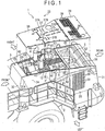
- Fig. 1 is an exploded perspective view showing a part of a working vehicle 1 provided with a cooling structure of an engine compartment 4 according to the exemplary embodiment of the invention.
- the working vehicle 1 is in a form of a wheel loader including a front frame (not shown) and a rear frame 2 connected to the front frame in a manner capable of being articulated.
- Working equipment that includes a boom, a bell crank, a bucket and hydraulic actuators that actuate the boom, bell crank and the bucket is provided on the front frame of the working vehicle 1. It should be noted that an illustration and a description of the working equipment are omitted since the working equipment is not directly relevant to the invention.
- the engine compartment 4 and a heat exchanger compartment 5 which are covered with an exterior cover 3 are juxtaposed in a front-rear direction.
- the engine compartment 4 and the heat exchanger compartment 5 are separated from each other by a first partitioning wall 6.
- the first partitioning wall 6 vertically separates the engine compartment 4 from the heat exchanger compartment 5.
- a periphery of the first partitioning wall 6 is close to or in contact with an inner surface of the exterior cover 3.
- the exterior cover 3 is attached via a support frame that stands on the rear frame 2, and the like.
- the exterior cover 3 includes: side covers 31, 31 that respectively form right and left side walls of the engine compartment 4 and the heat exchanger compartment 5, a front cover 32 that forms a front-side wall of the engine compartment 4, a rear grill (not shown) that is openably/closeably attached to a frame 56 (see Fig. 4 ) in a rear portion of the heat exchanger compartment 5, and a hood 3 that forms a ceiling of the engine compartment 4 and the heat exchanger compartment 5.
- the side cover 31 has a first side cover 34 in front of the first partitioning wall 6 and a second side cover 35 behind the first partitioning wall 6.
- the hood 33 has a first upper cover 36 with which a front portion of the engine compartment 4 is covered, a second upper cover 37 with which a rear portion of the engine compartment 4 is covered, and a third upper cover 38 with which the entire heat exchanger compartment 5 is covered.
- the first to third upper covers 36 to 38 are detachably attached to the side cover 31, the front cover 32 and the like by an appropriate fastening means (e.g., a bolt).
- the engine compartment 4 houses: an engine (not shown) mounted on the rear frame 2; an exhaust turbocharger 41, an EGR device, and an exhaust gas aftertreatment device 42 which are installed in the engine, pipes of these components and other auxiliary devices.
- the engine compartment 4 is divided into a front section and a rear section by a second partitioning wall 7 above the engine. Specifically, right and left side ends of the second partitioning wall 7 are close to or in contact with a vertical surface of a later-described ventilation duct 8 while a top end of the second partitioning wall 7 is close to or in contact with a lower surface of the second upper cover 37, whereby the compartment 4 is divided into the front section and the rear section.
- the exhaust gas aftertreatment device 42 is disposed in a space in front of the second partitioning wall 7 while the other devices including the exhaust turbocharger 41 are disposed in a space behind the second partitioning wall 7.
- the heat exchanger compartment 5 houses a radiator 51 that cools an engine cooling water, an after-cooler 52 that cools intake air (supplied air) supercharged by the exhaust turbocharger 41, a fan shroud 53 ( Fig. 3 ) disposed behind the radiator 51, an electric or hydraulic cooling fan 54 ( Fig. 3 ) that is rotated with a part partially projecting beyond the fan shroud 53, and pipes of the components 51 to 54.
- a capacitor for an air conditioner which is to be provided in the cab, may be provided in the heat exchanger compartment 5.
- a rectangular frame plate 55 in a planar view is provided over the heat exchanger compartment 5.
- the third upper cover 38 is attached over the frame plate 55.
- the pipes of the radiator 51 and the after-cooler 52 penetrate the first partitioning wall 6 to be laid in the heat exchanger compartment 5 and the engine compartment 4.
- the cooling fan 54 is pivotally movable in a rear direction along with a frame that supports the cooling fan 54 in the same manner as the rear grill. By pivotally moving the cooling fan 54 so that the cooling fan 54 is separated from a radiation surface of the radiator 51, maintenance for clogging and the like of the radiator 51 can be performed.
- cooling air flows into the heat exchanger compartment 5 through inlets 39 provided on the side cover 31 and the third upper cover 38 and a gap formed in the rear frame 2 under the heat exchanger compartment 5.
- the inflow cooling air passes through the after-cooler 52 and the radiator 51, thereby cooling the intake air and the engine cooling water. Subsequently, the cooling air is discharged from the rear grill through the cooling fan 54.
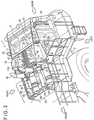
- Fig. 2 is a perspective view showing the ventilation structure of the engine compartment 4.
- Fig. 2 also shows a cooling structure of the urea aqueous solution pipe 47 connected to the exhaust gas aftertreatment device 42.
- the exhaust gas aftertreatment device 42 includes: a pair of DPF (Diesel Particulate Filter) devices 43, 43 disposed on both right and left sides of the front section of the engine compartment 4; and SCR (Selective Catalytic Reduction) devices 44, 44 juxtaposed in a right-left direction between the DPF devices 43, 43.
- DPF Diesel Particulate Filter
- SCR Selective Catalytic Reduction
- An exhaust pipe connected to a turbine outlet of the exhaust turbocharger 41 is laid to a side of the engine compartment 4 to extend near the front of the engine, where an end of the exhaust pipe is bifurcated.
- a first portion of the bifurcated exhaust pipe is connected to a front portion of the DPF device 43 disposed to the left of the engine compartment 4.
- Exhaust gas flows into the DPF device 43 through the first portion.
- the inflow exhaust gas flows in the rear direction through the cylindrical DPF device 43 provided in the front-rear direction of the vehicle. Particulate matters are collected by an internal filter of the DPF device 43. Subsequently, the inflow exhaust gas flows into a mixing pipe 45 connected to a rear portion of the DPF device 43.
- the mixing pipe 45 extends in a front direction and an end of the mixing pipe 45 is connected to a front portion of the left one of the SCR devices 44. In other words, the exhaust gas flows in the front direction through the mixing pipe 45.
- an injector for injecting a urea aqueous solution is attached to a base end (near the DPF device 43) of the mixing pipe 45.
- the urea aqueous solution injected from the injector into the mixing pipe 45 is thermally decomposed into ammonia by heat of the exhaust gas.
- the ammonia flows into the SCR device 44 along with the exhaust gas.
- the inflow exhaust gas and ammonia in the SCR device 44 flow in the rear direction through the cylindrical SCR device 44 in the front-rear direction of the vehicle and are supplied to a reduction-causing catalyst in the SCR device 44, thereby purifying nitrogen oxides in the exhaust gas.
- the exhaust gas in which nitrogen oxides are purified is discharged to the outside from the tail pipe 46 connected to a rear portion of the SCR device 44.
- a second portion of the bifurcated exhaust pipe passes in front of the engine to extend to the right of the engine and is connected to the front portion of the DPF device 43 disposed to the right of the engine.
- subsequent flow and aftertreatment of the exhaust gas flowing into the DPF device 43 are the same as those in the DPF device disposed to the left of the engine compartment 4 and can be understood from the above description. Accordingly, the description herein is omitted.
- the pair of SCR devices 44, 44 are disposed at the center over the engine.
- the DPF devices 43, 43 are respectively positioned at both shoulders of the engine at a level lower than the SCR devices 44, 44.
- the side cover 31 shown in Fig. 1 has a slant surface 31 A that is slant downward from the center of the vehicle on the right and left sides of the vehicle at the areas corresponding to the positions of the disposed DPF device 43 and SCR device 44. With the slant surface 31 A, visibility of right and left sides of the rear portion of the vehicle from the cab is improved.
- the ventilation duct 8 is provided approximately from the middle of the engine compartment 4 to the rear portion of the heat exchanger compartment 5.
- the aforementioned slant surface 31 A is provided in the front-rear direction on an upper portion of each of the side covers 31.
- a reinforcing member 81 is attached to an inner surface of each of the side covers at a position substantially corresponding to the slant surface 31 A.
- the reinforcing member 81 is removed from each of the side covers 31 for convenience.
- the reinforcing member 81 is intended to improve rigidity of each of the side covers 31 and includes: a first reinforcing member 82 that is provided to the first side cover 34 to be positioned in the engine compartment 4; and a rear-positioned second reinforcing member 83 that is provided to the second side cover 35 to be positioned in the heat exchanger compartment 5.
- the first and second reinforcing members 82 and 83 are shaped in an L-cross section.
- the ventilation duct 8 is formed using an inner surface (a surface facing the side cover 31) of the reinforcing member 81 and an inner surface of the side cover 31.
- the formed internal space functions as an air passage of the ventilation duct 8.
- the first and second reinforcing members 82 and 83 are separated from each other by a bridging frame 61 (also see Figs. 3 and 4 ) that bridges the right and left second side covers 31 (the second reinforcing members 83). Accordingly, each of the ventilation ducts 8 is divided in the middle of the front-rear direction by an end of the bridging frame 61. However, a communicating portion 62 is provided at the divided portion, so that air securely flows between the first and second reinforcing members 82 and 83.
- the bridging frame 61 is provided at a position corresponding to an upper portion of the first partitioning wall 6. An upper surface of the bridging frame 61 supports a frame on the front side of the frame plate 55.
- a front end of the ventilation duct 8 is positioned near the second partitioning wall 7 of the engine compartment 4 and is open toward the exhaust gas aftertreatment device 42 disposed in front of the second partitioning wall 7.
- the ventilation duct 8 not only air heated by heat of the engine but also air heated by heat of the exhaust gas aftertreatment device 42 are forcibly sucked.
- air heated by the engine and the exhaust turbocharger 41 is also sucked from the space behind the second partitioning wall 7 through under the second partitioning wall 7.
- a cross-sectional area of the air passage of the ventilation duct 8 is gradually reduced from the front end to the rear end of the ventilation duct 8.
- the ventilation duct 8 is in a tapered shape. Accordingly, at the rear end having a reduced cross-sectional area, a negative pressure generated by rotation of the cooling fan 54 can favorably work.
- pressure gradient can be formed in a long region extending over the ventilation duct 8 in the front-rear direction. Consequently, air in the engine compartment 4 can be reliably sucked in the rear direction.
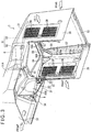
- Fig. 3 is a perspective view showing the exterior cover 3 seen from a lower side, in which the ventilation structure of the invention is provided.
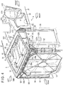
- Fig. 4 is a perspective view showing a principal part of the ventilation structure seen from the rear. It should be noted that the first and second partitioning walls 6 and 7 are not shown in Fig. 3 and the second partitioning wall 7 is not shown in Fig. 4 .
- a portal frame 56 standing on the rear frame 2 ( Figs. 1 and 2 ) is attached to a rear end of the exterior cover 3.
- the portal frame 56 includes: a pair of right and left vertical frames 57, 57 that are respectively attached to vertical rear ends of the second side covers 35; a horizontal frame 58 that bridges top ends of the vertical frames 57, 57; and an intermediate frame 59 that is provided under the horizontal frame 58 and bridges the vertical frames 57, 57.
- Each of the vertical frames 57 has an L-shaped cross section and stands with a corner facing an inside of the vehicle.
- a communication opening 57A is provided in each of pieces forming the L shape of an upper portion of the vertical frame 57.
- the portion of each of the vertical frames 57 in which the communication openings 57A are provided is covered with vertical ribs and a cover 57B to be laterally welded or the like.
- the horizontal frame 58 is provided by a channel member having a concave cross section and is set with an opening facing upward.
- the upward opening of the horizontal frame 58 is covered with a third upper cover 38, whereby the horizontal frame 58 functions as an air passage in the right and left direction.
- a plurality of communication openings 58A are provided in the longitudinal direction on a bottom of the horizontal frame 58.
- a cutout 58B is provided by cutting out each longitudinal end of a front web of the horizontal frame 58.
- the cutout 58B is connected with a rear end of the second reinforcing member 83 forming the reinforcing member 81, through which the ventilation duct 8 intercommunicates with the air passage in the horizontal frame 58.
- the intermediate frame 59 is formed in an elongated plate. Both longitudinal sides of the intermediate frame 59 are bent downward and bonded to the vertical frames 57. Also in the intermediate frame 59, communication openings 59A similar to the communication opening 58A are provided at positions each substantially corresponding to the communication opening 58A of the horizontal frame 58.
- a space surrounded by the upper portions of the vertical frames 57, the horizontal frame 58, and the intermediate frame 59 is covered with plates 56A on front and back sides of the space.
- the space covered with the plates 56A intercommunicates with the upper air passage through the communication openings 58A of the horizontal frame 58 while communicating with an inner space surrounded by the portal frame 56 through the communication openings 59A of the intermediate frame 59.
- the ventilation duct 8 intercommunicates with the inner space of the portal frame 56 through the space surrounded by the frames 57 to 59.
- substantially triangular spaces defined by each of the inclined sides of the intermediate frame 59 intercommunicate with spaces covered with the covers 57B in the upper portions of the vertical frames 57 through a first one of the communication openings 57A provided in each of the vertical frames 57.
- a communication opening 83A is provided on the bottom of each of the second reinforcing members 83.
- a corner member 84 is provided at a corner formed by each of the vertical frames 57 and each of the second reinforcing members 83 so that a second one of the communication openings 57A and the communication opening 83A are covered with the corner member 84.
- the ventilation duct 8 also intercommunicates with the inner space of the portal frame 56 through the spaces surrounded by each of the corner members 84, the upper portion of each of the vertical frames 57 and the frames 57 to 59.
- the fan shroud 53 which is a substantially octagonal frame, is housed in the inner space of the portal frame 56.
- the cooling fan 54 is rotated inside the fan shroud 53.
- An upper portion of the fan shroud 53 is close to the intermediate frame 59.
- Communication openings 53A are provided in the upper portion of the fan shroud 53 in a manner to correspond to each of the communication openings 59A of the intermediate frame 59.
- the communication openings 53A are open toward a surrounding area of the cooling fan 54, more specifically, toward a position that is adjacent to a rotation track of the outermost periphery of the cooling fan 54 and where a negative pressure is generated by the rotation of the cooling fan 54.
- the ventilation structure of the engine compartment is provided so that the negative-pressure generating part within the fan shroud 53 intercommunicates with the engine compartment 4 through the fan shroud 53, the inside of the portal frame 56 surrounding the fan shroud 53, and the ventilation duct 8 integrated with the exterior cover 3.
- Fig. 4 shows an open state of the inspection hatch 3 I B that is openably and closeably provided to the right side cover 31.
- the part of each of the reinforcing members 81 (the first reinforcing member 82) corresponding to the inspection hatch 31 defines an opening/closing portion 81 A that is openable/closeable integrally with the inspection hatch 31.
- a negative pressure generated by the driving of the cooling fan 54 causes air that is closer to a negative-pressure-generated part (e.g., the air in the portal frame 56) to start being sucked, so that the air in the engine compartment 4 is gradually sucked into the ducts 8.
- the sucked air passes through the ventilation ducts 8, which means the air flows in the rear direction bypassing the heat exchanger compartment 5. Since each of the ventilation ducts 8 is shielded from the heat exchanger compartment 5, air does not flow into the ventilation ducts 8 from the heat exchanger compartment 5, but the air in the engine compartment 4 is reliably sucked through the ventilation ducts 8.
- the air flowing through the ventilation duct 8 partially flows into the horizontal frames 58 of the portal frame 56 from the rear end of each of the ventilation ducts 8 and is drawn inside the fan shroud 53 through the space surrounded by the frames 57 to 59. Moreover, the rest of the air flowing through the ventilation ducts 8 flows into the upper portion of each of the vertical frames 57 of the portal frame 56 from the rear end of the ventilation ducts 8 through the corner members 84 and is simultaneously drawn inside the fan shroud 53 through the space surrounded by the frames 57 to 59.
- the drawn air is discharged outside by the rotation of the cooling fan 54.
- a volume equivalent to that of the air discharged from the engine compartment 4 is drawn in as fresh air from the outside through under the engine compartment 4 and is again sucked from the ventilation ducts 8. This operation is repeated for ventilation of the engine compartment 4.
- an injector (not shown) is attached to a rear portion of the mixing pipe 45 of the exhaust gas aftertreatment device 42.
- the urea aqueous solution pipe 47 is connected to the injector.
- the urea aqueous solution pipe 47 extends from a urea aqueous solution tank set under the heat exchanger compartment 5 into the engine compartment 4 through the heat exchanger compartment 5 to be connected to the injector.
- a supply module is provided in the course of the urea aqueous solution pipe 47. With the supply module, the urea aqueous solution is pumped from the urea aqueous solution tank to the injector through the urea aqueous solution pipe 47.
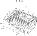
- Fig. 5 is a perspective view showing the cooling structure in the exemplary embodiment.
- Fig. 6 is a cross-sectional perspective view showing a principal part of the cooling structure.
- a pipeline-forming member 10 in which the urea aqueous solution pipe 47 is installed is provided on the rear of the second partitioning wall 7 in the engine compartment 4.
- the pipeline-forming member 10 is provided immediately under the second upper cover 37 of the hood 33 and in contact with the lower surface of the second upper cover.
- the first and second pipelines 11 and 12 are each a cross-sectionally concaved groove having partitioning walls with an opening upward.
- a rear end of the first pipeline 11 penetrates the first partitioning wall 6 and is enlarged in a funneled shape to be open as an opening 11 A in the heat exchanger compartment 5.
- two urea aqueous solution pipes 47 are used when installed in the pipeline-forming member 10.
- the two urea aqueous solution pipes 47 after passing through the heat exchanger compartment 5 are installed from the opening 11 A through the first pipeline 11 and divided into right and left portions of the second pipeline 12.
- Each of the urea aqueous solution pipes 47 penetrates the second partitioning wall 7 from each end of the second pipeline 12 to extend to the front section in front of the second partitioning wall 7 to be connected to the injector.
- the pipeline-forming member 10 further includes an air passage 13 (insulation space) in a T-shape in a planar view which is adjacent to the first and second pipelines 11 and 12.
- the air passage 13 includes first passages 14 that are laterally juxtaposed with the first pipeline 11 and second passages 15 that are juxtaposed at the rear of the second pipeline 12.
- the first and second passages 14 and 15 are also open upward.
- the first passages 14 are defined by the partitioning walls of the first pipeline 11 and outer partitioning walls that cover the partitioning walls of the first pipeline 11. Cooling air flows through space between the inner and outer partitioning walls as described later.
- the first passages 14 are present under the first pipeline 11 in a cross-sectional view. In other words, the sides and the bottom of the first pipeline 11 are covered with the first passages 14 in a cross-sectional view.
- the respective rear ends of the first passages 14 penetrate the first partitioning wall 6 to be open in the heat exchanger compartment 5.
- the respective openings of the first passages 14 face a bracket 63 that supports the pipes in the heat exchanger compartment 5.
- the bracket 63 is attached to the partitioning wall 6 while being open downward.
- Each of the second passages 15 is a cross-sectionally concaved groove having partitioning walls and is attached to a side of the second pipeline 12.
- a rear end of the aforementioned pipeline-forming member 10 is supported by the first partitioning wall 6 while a front end of the pipeline-forming member 10 is supported by the right and left side covers 31 through an appropriate bracket.
- the upward opening of the pipeline-forming member 10 is covered with the second upper cover 37. By covering the upward opening, the first and second pipelines 11 and 12 and the first and second passages 14 and 15 are formed in a tunnel.
- the second upper cover 37 includes: a pair of right and left elongated air intake holes 37A, 37A that are positioned above the second pipeline 12; a pair of air intake holes 37B, 37B that are similar to the air intake holes 37A, 37A and are positioned above the second passages 15; and a plurality of air intake holes 37C that are similar to the air intake holes 37A, 37A and are positioned above the first passages 14 in the front-rear direction.
- the cooling air flowing from the air intake holes 37B flows toward the rear through the second pipeline 12 and the first pipeline 11.
- the urea aqueous solution pipes 47 and the first and second pipelines 11 and 12 that house the urea aqueous solution pipes 47 are cooled.
- the cooling air in this arrangement flows in a direction opposite to the urea aqueous solution flowing through the urea aqueous solution pipes 47. Subsequently, the cooling air flows into the heat exchanger compartment 5 from the enlarged opening 11A.
- the cooling air flowing through the air intake holes 37B and 37C flows in the rear direction through the first and second passages 14 and 15 to block heat of the engine and the like in the engine compartment 4 from the first and second pipelines 11 and 12 and the urea aqueous solution pipes 47. Subsequently, the cooling air flows into the heat exchanger compartment 5 from the opening (not shown) provided in the first partitioning wall 6 and is regulated to flow downward by the bracket 63, thereby flowing along the first partitioning wall 6.
- the cooling air flowing in the heat exchanger compartment 5 is transferred toward the after-cooler 52 and the radiator 51 along with another cooling air sucked by the cooling fan 54, and subsequently discharged from the rear grill through the cooling fan 54.
- the urea aqueous solution pipes 47 are arranged within the pipeline-forming member 10 in the engine compartment 4, the urea aqueous solution pipes 47 are forcibly cooled by the cooling air flowing through the pipeline-forming member 10, so that the urea aqueous solution pipes 47 are unlikely to be thermally influenced in the engine compartment 4 to inhibit the urea aqueous solution from being deteriorated.
- the urea aqueous solution pipes 47 can also be shielded from heat by the cooling air flowing through the first and second passages 14 and 15 outside of the first and second pipelines 11 and 12 and the partitioning walls of the first and second passages 14 and 15, so that the urea aqueous solution pipes 47 are further unlikely to be thermally influenced.
- the pipeline-forming member 10 may be provided inside the side cover and the like.
- the side cover desirably includes: a hatch openable/closeable against surrounding portions; and a portion of the surrounding portions to which the pipeline-forming member is attached. According to this arrangement, even when the hatch is opened, the pipeline-forming member is not drawn out together with the hatch and maintenance of the urea aqueous solution pipe can be performed while the pipeline-forming member is left in the engine compartment.
- the pipeline-forming member 10 is in contact with the lower surface of the second upper cover 37, so that the first and second pipelines 11 and 12 and the first and second passages 14 and 15, which are shaped in a groove, intercommunicate with the outside of the engine compartment 4 through the air intake holes 37A, 37B and 37C of the second upper cover 37.
- the pipeline-forming member is not necessarily in contact with the exterior cover (e.g., the second upper cover 37) but may be close to the exterior cover with a predetermined gap.
- the pipelines and the passages are shaped in a tube instead of a groove and a communication portion is preferably provided to the tube for intercommunication of the pipelines and the passages with the air intake holes.
- a communication portion is preferably provided to one of the exterior cover and the pipeline-forming member in a detachable manner.
- cooling air flows in the first and second pipelines 11 and 12 and the first and second passages 14 and 15 of the pipeline-forming member 10. Even in the arrangement in which the cooling air flows only into the passages, heat from the engine and the exhaust gas aftertreatment device can be insulated from the urea aqueous solution pipe of the pipelines. Accordingly, such an arrangement is also usable. On the contrary, the cooling air may flow only into the pipelines so that the passages function as the insulation space. Even with this arrangement, substantially the same effects are obtainable.
- the pipeline-forming member 10 has an air passage consisting of the first and second passages 14 and 15.
- an air passage may be provided as needed in consideration of the degree of the increase in the temperature of the engine compartment.
- the air passage is not necessarily provided.
- the invention is applicable not only to a urea aqueous solution pipe of an exhaust gas aftertreatment device installed in a wheel loader but also to a urea aqueous solution pipe of various working vehicles such as construction machines (e.g., a bulldozer and a hydraulic excavator) other than the wheel loader, agricultural machines (e.g., a tractor), and further to a urea aqueous solution pipe of a mobile engine generator.
- construction machines e.g., a bulldozer and a hydraulic excavator
- agricultural machines e.g., a tractor
Claims (3)
- Structure de refroidissement d'un tuyau de solution aqueuse d'urée conduisant à un dispositif de réduction catalytique sélective (44) dans un dispositif post-traitement des gaz d'échappement (42), le dispositif post-traitement des gaz d'échappement (42) étant prévu dans un compartiment moteur (4) qui est adjacent à un ventilateur de refroidissement (54) à travers lequel de l'air de refroidissement est délivré à un échangeur de chaleur, l'échangeur de chaleur étant disposé dans un compartiment d'échangeur de chaleur (5) ; l'air dans le compartiment d'échangeur de chaleur (5) et le compartiment moteur étant évacué par le ventilateur de refroidissement (54) ; le dispositif de réduction catalytique (44) utilisant de l'ammoniac obtenu à partir d'une solution aqueuse d'urée et d'un agent réducteur, le tuyau de solution aqueuse d'urée délivrant la solution aqueuse d'urée au dispositif de réduction catalytique sélective (44) à travers le compartiment moteur (4) ; le dispositif de réduction catalytique sélective (44) étant disposé au-dessus du moteur, la structure de refroidissement comprenant :un élément de formation de pipeline (10) prévu dans le compartiment moteur (4) et comprenant un pipeline (11, 12) dans lequel est agencé le tuyau de solution aqueuse d'urée (47), l'élément de formation de pipeline (10) étant prévu dans une position proche de l'intérieur d'un capot (37) définissant le plafond du compartiment moteur (4) et en contact avec celui-ci ; etun trou d'admission d'air (37A, 37B, 37C) qui est prévu sur le capot (33) pour faire intercommuniquer le pipeline (11, 12) avec l'extérieur du compartiment moteur (4) ; dans lequelune extrémité du pipeline (11, 12) intercommunique avec le compartiment d'échangeur de chaleur (5),le tuyau de solution aqueuse d'urée (47) est disposé dans le pipeline (11, 12) depuis un réservoir de solution aqueuse d'urée disposé en dessous du compartiment d'échangeur de chaleur (5) à travers le compartiment d'échangeur de chaleur (5) et une extrémité de l'élément de formation de pipeline (10) ; etl'air de refroidissement sous la forme de l'air extérieur aspiré par le ventilateur de refroidissement (54) s'écoule à travers le trou d'admission d'air (37A, 37B, 37C) dans le pipeline (11, 12) pour être délivré au compartiment d'échangeur de chaleur (5) pour refroidir le tuyau de solution aqueuse d'urée (47).
- Structure de refroidissement d'un tuyau de solution aqueuse d'urée conduisant à un dispositif de réduction catalytique sélective (44) dans un dispositif post-traitement des gaz d'échappement (42), le dispositif post-traitement des gaz d'échappement (42) étant prévu dans un compartiment moteur (4) qui est adjacent à un ventilateur de refroidissement (54) à travers lequel de l'air de refroidissement est délivré à un échangeur de chaleur, l'échangeur de chaleur étant disposé dans un compartiment d'échangeur de chaleur (5) ; l'air dans le compartiment d'échangeur de chaleur (5) et le compartiment moteur (4) étant évacué par le ventilateur de refroidissement (54) ; le dispositif de réduction catalytique (44) utilisant de l'ammoniac obtenu à partir d'une solution aqueuse d'urée et d'un agent réducteur, le tuyau de solution aqueuse d'urée (47) délivrant la solution aqueuse d'urée au dispositif de réduction catalytique sélective (44) à travers le compartiment moteur (4) ; le dispositif de réduction catalytique sélective (44) étant disposé au-dessus du moteur, la structure de refroidissement comprenant :un élément de formation de pipeline (10) prévu dans le compartiment moteur (4) et comprenant un pipeline (11, 12) dans lequel est agencé le tuyau de solution aqueuse d'urée (47) et un espace d'isolation (13) juxtaposé avec le pipeline, l'élément de formation de pipeline (10) étant prévu dans une position proche de l'intérieur d'un capot (37) définissant le plafond du compartiment moteur (4) et en contact avec celui-ci ; etun trou d'admission d'air (37A, 37B, 37C) qui est prévu sur le capot (33) pour faire intercommuniquer le pipeline (11, 12) avec l'extérieur du compartiment moteur (4) ; dans lequelune extrémité du pipeline (11, 12) intercommunique avec le compartiment d'échangeur de chaleur (5),le tuyau de solution aqueuse d'urée (47) s'étend depuis un réservoir de solution aqueuse d'urée disposé en dessous du compartiment d'échangeur de chaleur (5) à travers le compartiment d'échangeur de chaleur (5) et une extrémité de l'élément de formation de pipeline (10) destiné à être disposé dans le pipeline (11, 12) ; etl'air de refroidissement sous la forme de l'air extérieur aspiré par le ventilateur de refroidissement (54) s'écoule à travers le trou d'admission d'air (37A, 37B, 37C) pour être délivré au compartiment d'échangeur de chaleur (5) pour refroidir le tuyau de solution aqueuse d'urée (47) dans au moins un du pipeline (11, 12) et de l'espace d'isolation (13).
- Structure de refroidissement d'un tuyau de solution aqueuse d'urée selon la revendication 1 ou 2, dans laquelle une partie du capot (33) en dessous duquel est positionné l'élément de formation de pipeline (10) peut être détachée du reste du recouvrement extérieur (3) ; et
l'élément de formation de pipeline (10) est fixé au reste du recouvrement extérieur (3).
Applications Claiming Priority (2)
| Application Number | Priority Date | Filing Date | Title |
|---|---|---|---|
| JP2012235913A JP5799001B2 (ja) | 2012-10-25 | 2012-10-25 | 尿素水溶液配管の冷却構造 |
| PCT/JP2013/073945 WO2014065023A1 (fr) | 2012-10-25 | 2013-09-05 | Structure de refroidissement d'un conduit de solution aqueuse d'urée |
Publications (3)
| Publication Number | Publication Date |
|---|---|
| EP2821608A1 EP2821608A1 (fr) | 2015-01-07 |
| EP2821608A4 EP2821608A4 (fr) | 2015-10-28 |
| EP2821608B1 true EP2821608B1 (fr) | 2016-05-25 |
Family
ID=50544404
Family Applications (1)
| Application Number | Title | Priority Date | Filing Date |
|---|---|---|---|
| EP13849921.5A Active EP2821608B1 (fr) | 2012-10-25 | 2013-09-05 | Structure de refroidissement d'un conduit de solution aqueuse d'urée |
Country Status (5)
| Country | Link |
|---|---|
| US (1) | US9394817B2 (fr) |
| EP (1) | EP2821608B1 (fr) |
| JP (1) | JP5799001B2 (fr) |
| CN (1) | CN104204435B (fr) |
| WO (1) | WO2014065023A1 (fr) |
Families Citing this family (15)
| Publication number | Priority date | Publication date | Assignee | Title |
|---|---|---|---|---|
| US9631342B2 (en) * | 2014-08-19 | 2017-04-25 | Komatsu Ltd. | Work vehicle |
| JP6438341B2 (ja) * | 2014-10-15 | 2018-12-12 | ヤンマー株式会社 | 作業車両 |
| JP6393777B2 (ja) * | 2014-11-21 | 2018-09-19 | 株式会社Kcm | 産業用車両 |
| WO2016092868A1 (fr) | 2014-12-12 | 2016-06-16 | 株式会社小松製作所 | Engin de chantier |
| JP6295195B2 (ja) * | 2014-12-26 | 2018-03-14 | 株式会社Kcm | 作業機械 |
| US9556586B2 (en) | 2015-03-10 | 2017-01-31 | Komatsu Ltd. | Working vehicle |
| WO2015137354A1 (fr) * | 2015-03-10 | 2015-09-17 | 株式会社小松製作所 | Véhicule industriel |
| US10100579B2 (en) * | 2015-06-04 | 2018-10-16 | The Charles Machine Works, Inc. | Exhaust assembly cooling system |
| JP6549455B2 (ja) * | 2015-09-24 | 2019-07-24 | 住友建機株式会社 | ショベル |
| WO2017068734A1 (fr) * | 2015-10-23 | 2017-04-27 | 株式会社小松製作所 | Tracteur |
| JP6548224B2 (ja) | 2016-03-29 | 2019-07-24 | 日立建機株式会社 | 作業機械 |
| JP6284281B2 (ja) * | 2016-04-07 | 2018-02-28 | ヤンマー株式会社 | トラクタ |
| US10975879B2 (en) | 2018-07-18 | 2021-04-13 | The Charles Machine Works, Inc. | Centrifugal fan |
| DE102018213895A1 (de) * | 2018-08-17 | 2020-02-20 | Robert Bosch Gmbh | Anordnung zur Nachbehandlung des Abgases einer Brennkraftmaschine und Verfahren zum Betreiben einer solchen |
| US11767780B2 (en) | 2020-02-13 | 2023-09-26 | The Charles Machine Works, Inc. | Engine cooling system |
Family Cites Families (25)
| Publication number | Priority date | Publication date | Assignee | Title |
|---|---|---|---|---|
| JPH0728908Y2 (ja) * | 1991-03-28 | 1995-07-05 | 株式会社新潟鉄工所 | 排ガス還元剤の噴霧装置 |
| JPH0618619U (ja) * | 1992-08-20 | 1994-03-11 | 株式会社小松製作所 | 内燃機関の消音器 |
| DE19806265C5 (de) * | 1998-02-16 | 2004-07-22 | Siemens Ag | Dosiersystem |
| JP4450298B2 (ja) | 2000-01-12 | 2010-04-14 | 株式会社小松製作所 | 建設機械のエンジン冷却風路 |
| JP2002221110A (ja) * | 2001-01-22 | 2002-08-09 | Nec Eng Ltd | ディーゼルエンジン発電機システムにおける燃料凍結防止方法 |
| JP2003020936A (ja) * | 2001-07-03 | 2003-01-24 | Komatsu Ltd | NOx還元触媒用液体還元剤タンクの配置構造 |
| EP1691046B1 (fr) | 2003-09-19 | 2013-04-24 | Nissan Diesel Motor Co., Ltd. | Appareil de purification de gaz d'échappement pour un moteur à combustion interne |
| JP2007283801A (ja) * | 2006-04-12 | 2007-11-01 | Hitachi Constr Mach Co Ltd | 建設機械 |
| JP4656039B2 (ja) | 2006-10-19 | 2011-03-23 | 株式会社デンソー | エンジンの排気浄化装置 |
| JP2008156835A (ja) * | 2006-12-21 | 2008-07-10 | Shin Caterpillar Mitsubishi Ltd | 排ガス後処理装置を設けた建設機械 |
| JP5273933B2 (ja) * | 2007-03-28 | 2013-08-28 | 株式会社小松製作所 | 建設車両 |
| JP2008303786A (ja) * | 2007-06-07 | 2008-12-18 | Toyota Motor Corp | 内燃機関の排気浄化装置 |
| JP2009117127A (ja) * | 2007-11-05 | 2009-05-28 | Toyota Motor Corp | 管加熱装置 |
| EP2159389B1 (fr) * | 2008-08-29 | 2012-01-25 | Caterpillar Inc. | Système de ventilation pour compartiment de post-traitement |
| US20100186381A1 (en) * | 2009-01-26 | 2010-07-29 | Caterpillar Inc | Exhaust system thermal enclosure |
| JP2010261373A (ja) * | 2009-05-08 | 2010-11-18 | Kobelco Contstruction Machinery Ltd | 作業機械 |
| JP5369919B2 (ja) * | 2009-06-12 | 2013-12-18 | コベルコ建機株式会社 | 作業機械 |
| JP5735973B2 (ja) * | 2009-11-05 | 2015-06-17 | ジョンソン、マッセイ、インコーポレイテッドJohnson Matthey Inc. | 二次燃焼排気を用いて含水尿素(尿素水溶液)をアンモニア蒸気に気化させるシステムおよび方法 |
| US8206476B2 (en) * | 2010-04-01 | 2012-06-26 | Deere & Company | Cover for a diesel particulate filter |
| US8919469B2 (en) * | 2010-08-26 | 2014-12-30 | Caterpillar Inc. | Ventilation system for engine and aftertreatment compartments and components |
| JP5839791B2 (ja) * | 2010-10-14 | 2016-01-06 | 三菱重工業株式会社 | 舶用scr還元剤供給システム |
| JP5649463B2 (ja) * | 2011-01-14 | 2015-01-07 | 日立建機株式会社 | 建設機械 |
| US20130014496A1 (en) * | 2011-07-15 | 2013-01-17 | Caterpillar Inc. | Cooling system for engine aftertreatment system |
| JP5310804B2 (ja) | 2011-08-01 | 2013-10-09 | トヨタ自動車株式会社 | 内燃機関の排気浄化装置 |
| US20130291523A1 (en) * | 2012-05-02 | 2013-11-07 | Caterpillar, Inc. | Cooling System for Diesel Emissions Fluid Injector |
-
2012
- 2012-10-25 JP JP2012235913A patent/JP5799001B2/ja active Active
-
2013
- 2013-09-05 US US14/414,640 patent/US9394817B2/en active Active
- 2013-09-05 CN CN201380017388.XA patent/CN104204435B/zh active Active
- 2013-09-05 EP EP13849921.5A patent/EP2821608B1/fr active Active
- 2013-09-05 WO PCT/JP2013/073945 patent/WO2014065023A1/fr active Application Filing
Also Published As
| Publication number | Publication date |
|---|---|
| CN104204435A (zh) | 2014-12-10 |
| EP2821608A1 (fr) | 2015-01-07 |
| US9394817B2 (en) | 2016-07-19 |
| WO2014065023A1 (fr) | 2014-05-01 |
| CN104204435B (zh) | 2016-11-16 |
| JP5799001B2 (ja) | 2015-10-21 |
| JP2014084832A (ja) | 2014-05-12 |
| US20150176451A1 (en) | 2015-06-25 |
| EP2821608A4 (fr) | 2015-10-28 |
Similar Documents
| Publication | Publication Date | Title |
|---|---|---|
| EP2821608B1 (fr) | Structure de refroidissement d'un conduit de solution aqueuse d'urée | |
| EP2821613B1 (fr) | Structure de ventilation d'un compartiment moteur | |
| EP2752327B1 (fr) | Véhicule de chantier équipé d'un dispositif de post-traitement des gaz d'échappement | |
| EP2842783B1 (fr) | Véhicule de travail | |
| JP5635694B1 (ja) | 作業車両、及びホイールローダ | |
| JP5439634B1 (ja) | 排気ガス後処理装置を搭載した建設車両 | |
| EP3239411B1 (fr) | Machine d'opération | |
| EP3009759B1 (fr) | Véhicule utilitaire | |
| JP5996449B2 (ja) | 建設機械 | |
| JP2012219624A (ja) | 建設機械 | |
| WO2012105320A1 (fr) | Machine de construction | |
| JP5635695B1 (ja) | 作業車両、及びホイールローダ | |
| JP6385323B2 (ja) | 建設機械 | |
| KR20170107363A (ko) | 건설 기계 | |
| WO2016125201A1 (fr) | Véhicule industriel | |
| JP5438249B1 (ja) | ダンプトラック | |
| JP6869840B2 (ja) | 建設機械 | |
| JP2022065361A (ja) | 建設機械 |
Legal Events
| Date | Code | Title | Description |
|---|---|---|---|
| PUAI | Public reference made under article 153(3) epc to a published international application that has entered the european phase |
Free format text: ORIGINAL CODE: 0009012 |
|
| 17P | Request for examination filed |
Effective date: 20140929 |
|
| AK | Designated contracting states |
Kind code of ref document: A1 Designated state(s): AL AT BE BG CH CY CZ DE DK EE ES FI FR GB GR HR HU IE IS IT LI LT LU LV MC MK MT NL NO PL PT RO RS SE SI SK SM TR |
|
| AX | Request for extension of the european patent |
Extension state: BA ME |
|
| RA4 | Supplementary search report drawn up and despatched (corrected) |
Effective date: 20150925 |
|
| RIC1 | Information provided on ipc code assigned before grant |
Ipc: B01D 53/90 20060101ALI20150921BHEP Ipc: F01P 11/10 20060101ALI20150921BHEP Ipc: B62D 25/10 20060101ALI20150921BHEP Ipc: B01D 53/94 20060101ALI20150921BHEP Ipc: E02F 9/08 20060101ALI20150921BHEP Ipc: F01P 5/06 20060101ALI20150921BHEP Ipc: F01N 3/20 20060101AFI20150921BHEP |
|
| REG | Reference to a national code |
Ref country code: DE Ref legal event code: R079 Ref document number: 602013008125 Country of ref document: DE Free format text: PREVIOUS MAIN CLASS: F01N0003080000 Ipc: F01N0003200000 |
|
| GRAP | Despatch of communication of intention to grant a patent |
Free format text: ORIGINAL CODE: EPIDOSNIGR1 |
|
| RIC1 | Information provided on ipc code assigned before grant |
Ipc: B62D 25/10 20060101ALI20151203BHEP Ipc: B01D 53/90 20060101ALI20151203BHEP Ipc: F01N 13/14 20100101ALI20151203BHEP Ipc: E02F 9/08 20060101ALI20151203BHEP Ipc: F01N 3/20 20060101AFI20151203BHEP Ipc: B01D 53/94 20060101ALI20151203BHEP Ipc: F01P 11/10 20060101ALI20151203BHEP Ipc: F01P 5/06 20060101ALI20151203BHEP |
|
| DAX | Request for extension of the european patent (deleted) | ||
| INTG | Intention to grant announced |
Effective date: 20160105 |
|
| GRAS | Grant fee paid |
Free format text: ORIGINAL CODE: EPIDOSNIGR3 |
|
| GRAA | (expected) grant |
Free format text: ORIGINAL CODE: 0009210 |
|
| AK | Designated contracting states |
Kind code of ref document: B1 Designated state(s): AL AT BE BG CH CY CZ DE DK EE ES FI FR GB GR HR HU IE IS IT LI LT LU LV MC MK MT NL NO PL PT RO RS SE SI SK SM TR |
|
| REG | Reference to a national code |
Ref country code: GB Ref legal event code: FG4D |
|
| REG | Reference to a national code |
Ref country code: CH Ref legal event code: EP |
|
| REG | Reference to a national code |
Ref country code: IE Ref legal event code: FG4D Ref country code: AT Ref legal event code: REF Ref document number: 802522 Country of ref document: AT Kind code of ref document: T Effective date: 20160615 |
|
| REG | Reference to a national code |
Ref country code: DE Ref legal event code: R096 Ref document number: 602013008125 Country of ref document: DE |
|
| REG | Reference to a national code |
Ref country code: SE Ref legal event code: TRGR |
|
| REG | Reference to a national code |
Ref country code: LT Ref legal event code: MG4D |
|
| REG | Reference to a national code |
Ref country code: NL Ref legal event code: MP Effective date: 20160525 |
|
| PG25 | Lapsed in a contracting state [announced via postgrant information from national office to epo] |
Ref country code: FI Free format text: LAPSE BECAUSE OF FAILURE TO SUBMIT A TRANSLATION OF THE DESCRIPTION OR TO PAY THE FEE WITHIN THE PRESCRIBED TIME-LIMIT Effective date: 20160525 Ref country code: LT Free format text: LAPSE BECAUSE OF FAILURE TO SUBMIT A TRANSLATION OF THE DESCRIPTION OR TO PAY THE FEE WITHIN THE PRESCRIBED TIME-LIMIT Effective date: 20160525 Ref country code: NL Free format text: LAPSE BECAUSE OF FAILURE TO SUBMIT A TRANSLATION OF THE DESCRIPTION OR TO PAY THE FEE WITHIN THE PRESCRIBED TIME-LIMIT Effective date: 20160525 Ref country code: NO Free format text: LAPSE BECAUSE OF FAILURE TO SUBMIT A TRANSLATION OF THE DESCRIPTION OR TO PAY THE FEE WITHIN THE PRESCRIBED TIME-LIMIT Effective date: 20160825 |
|
| REG | Reference to a national code |
Ref country code: AT Ref legal event code: MK05 Ref document number: 802522 Country of ref document: AT Kind code of ref document: T Effective date: 20160525 |
|
| PG25 | Lapsed in a contracting state [announced via postgrant information from national office to epo] |
Ref country code: RS Free format text: LAPSE BECAUSE OF FAILURE TO SUBMIT A TRANSLATION OF THE DESCRIPTION OR TO PAY THE FEE WITHIN THE PRESCRIBED TIME-LIMIT Effective date: 20160525 Ref country code: GR Free format text: LAPSE BECAUSE OF FAILURE TO SUBMIT A TRANSLATION OF THE DESCRIPTION OR TO PAY THE FEE WITHIN THE PRESCRIBED TIME-LIMIT Effective date: 20160826 Ref country code: LV Free format text: LAPSE BECAUSE OF FAILURE TO SUBMIT A TRANSLATION OF THE DESCRIPTION OR TO PAY THE FEE WITHIN THE PRESCRIBED TIME-LIMIT Effective date: 20160525 Ref country code: ES Free format text: LAPSE BECAUSE OF FAILURE TO SUBMIT A TRANSLATION OF THE DESCRIPTION OR TO PAY THE FEE WITHIN THE PRESCRIBED TIME-LIMIT Effective date: 20160525 Ref country code: PT Free format text: LAPSE BECAUSE OF FAILURE TO SUBMIT A TRANSLATION OF THE DESCRIPTION OR TO PAY THE FEE WITHIN THE PRESCRIBED TIME-LIMIT Effective date: 20160926 |
|
| PG25 | Lapsed in a contracting state [announced via postgrant information from national office to epo] |
Ref country code: IT Free format text: LAPSE BECAUSE OF FAILURE TO SUBMIT A TRANSLATION OF THE DESCRIPTION OR TO PAY THE FEE WITHIN THE PRESCRIBED TIME-LIMIT Effective date: 20160525 |
|
| PG25 | Lapsed in a contracting state [announced via postgrant information from national office to epo] |
Ref country code: CZ Free format text: LAPSE BECAUSE OF FAILURE TO SUBMIT A TRANSLATION OF THE DESCRIPTION OR TO PAY THE FEE WITHIN THE PRESCRIBED TIME-LIMIT Effective date: 20160525 Ref country code: EE Free format text: LAPSE BECAUSE OF FAILURE TO SUBMIT A TRANSLATION OF THE DESCRIPTION OR TO PAY THE FEE WITHIN THE PRESCRIBED TIME-LIMIT Effective date: 20160525 Ref country code: DK Free format text: LAPSE BECAUSE OF FAILURE TO SUBMIT A TRANSLATION OF THE DESCRIPTION OR TO PAY THE FEE WITHIN THE PRESCRIBED TIME-LIMIT Effective date: 20160525 Ref country code: RO Free format text: LAPSE BECAUSE OF FAILURE TO SUBMIT A TRANSLATION OF THE DESCRIPTION OR TO PAY THE FEE WITHIN THE PRESCRIBED TIME-LIMIT Effective date: 20160525 Ref country code: SK Free format text: LAPSE BECAUSE OF FAILURE TO SUBMIT A TRANSLATION OF THE DESCRIPTION OR TO PAY THE FEE WITHIN THE PRESCRIBED TIME-LIMIT Effective date: 20160525 |
|
| PG25 | Lapsed in a contracting state [announced via postgrant information from national office to epo] |
Ref country code: SM Free format text: LAPSE BECAUSE OF FAILURE TO SUBMIT A TRANSLATION OF THE DESCRIPTION OR TO PAY THE FEE WITHIN THE PRESCRIBED TIME-LIMIT Effective date: 20160525 Ref country code: AT Free format text: LAPSE BECAUSE OF FAILURE TO SUBMIT A TRANSLATION OF THE DESCRIPTION OR TO PAY THE FEE WITHIN THE PRESCRIBED TIME-LIMIT Effective date: 20160525 Ref country code: BE Free format text: LAPSE BECAUSE OF NON-PAYMENT OF DUE FEES Effective date: 20160525 Ref country code: PL Free format text: LAPSE BECAUSE OF FAILURE TO SUBMIT A TRANSLATION OF THE DESCRIPTION OR TO PAY THE FEE WITHIN THE PRESCRIBED TIME-LIMIT Effective date: 20160525 |
|
| REG | Reference to a national code |
Ref country code: DE Ref legal event code: R097 Ref document number: 602013008125 Country of ref document: DE |
|
| PLBE | No opposition filed within time limit |
Free format text: ORIGINAL CODE: 0009261 |
|
| STAA | Information on the status of an ep patent application or granted ep patent |
Free format text: STATUS: NO OPPOSITION FILED WITHIN TIME LIMIT |
|
| PG25 | Lapsed in a contracting state [announced via postgrant information from national office to epo] |
Ref country code: MC Free format text: LAPSE BECAUSE OF FAILURE TO SUBMIT A TRANSLATION OF THE DESCRIPTION OR TO PAY THE FEE WITHIN THE PRESCRIBED TIME-LIMIT Effective date: 20160525 |
|
| REG | Reference to a national code |
Ref country code: CH Ref legal event code: PL |
|
| 26N | No opposition filed |
Effective date: 20170228 |
|
| PG25 | Lapsed in a contracting state [announced via postgrant information from national office to epo] |
Ref country code: SI Free format text: LAPSE BECAUSE OF FAILURE TO SUBMIT A TRANSLATION OF THE DESCRIPTION OR TO PAY THE FEE WITHIN THE PRESCRIBED TIME-LIMIT Effective date: 20160525 |
|
| REG | Reference to a national code |
Ref country code: IE Ref legal event code: MM4A |
|
| REG | Reference to a national code |
Ref country code: FR Ref legal event code: ST Effective date: 20170531 |
|
| PG25 | Lapsed in a contracting state [announced via postgrant information from national office to epo] |
Ref country code: LI Free format text: LAPSE BECAUSE OF NON-PAYMENT OF DUE FEES Effective date: 20160930 Ref country code: CH Free format text: LAPSE BECAUSE OF NON-PAYMENT OF DUE FEES Effective date: 20160930 Ref country code: FR Free format text: LAPSE BECAUSE OF NON-PAYMENT OF DUE FEES Effective date: 20160930 Ref country code: IE Free format text: LAPSE BECAUSE OF NON-PAYMENT OF DUE FEES Effective date: 20160905 |
|
| PG25 | Lapsed in a contracting state [announced via postgrant information from national office to epo] |
Ref country code: LU Free format text: LAPSE BECAUSE OF NON-PAYMENT OF DUE FEES Effective date: 20160905 |
|
| GBPC | Gb: european patent ceased through non-payment of renewal fee |
Effective date: 20170905 |
|
| PG25 | Lapsed in a contracting state [announced via postgrant information from national office to epo] |
Ref country code: HU Free format text: LAPSE BECAUSE OF FAILURE TO SUBMIT A TRANSLATION OF THE DESCRIPTION OR TO PAY THE FEE WITHIN THE PRESCRIBED TIME-LIMIT; INVALID AB INITIO Effective date: 20130905 |
|
| PG25 | Lapsed in a contracting state [announced via postgrant information from national office to epo] |
Ref country code: HR Free format text: LAPSE BECAUSE OF FAILURE TO SUBMIT A TRANSLATION OF THE DESCRIPTION OR TO PAY THE FEE WITHIN THE PRESCRIBED TIME-LIMIT Effective date: 20160525 Ref country code: MK Free format text: LAPSE BECAUSE OF FAILURE TO SUBMIT A TRANSLATION OF THE DESCRIPTION OR TO PAY THE FEE WITHIN THE PRESCRIBED TIME-LIMIT Effective date: 20160525 Ref country code: CY Free format text: LAPSE BECAUSE OF FAILURE TO SUBMIT A TRANSLATION OF THE DESCRIPTION OR TO PAY THE FEE WITHIN THE PRESCRIBED TIME-LIMIT Effective date: 20160525 Ref country code: MT Free format text: LAPSE BECAUSE OF NON-PAYMENT OF DUE FEES Effective date: 20160930 Ref country code: IS Free format text: LAPSE BECAUSE OF FAILURE TO SUBMIT A TRANSLATION OF THE DESCRIPTION OR TO PAY THE FEE WITHIN THE PRESCRIBED TIME-LIMIT Effective date: 20160525 |
|
| PG25 | Lapsed in a contracting state [announced via postgrant information from national office to epo] |
Ref country code: BG Free format text: LAPSE BECAUSE OF FAILURE TO SUBMIT A TRANSLATION OF THE DESCRIPTION OR TO PAY THE FEE WITHIN THE PRESCRIBED TIME-LIMIT Effective date: 20160525 Ref country code: GB Free format text: LAPSE BECAUSE OF NON-PAYMENT OF DUE FEES Effective date: 20170905 |
|
| PG25 | Lapsed in a contracting state [announced via postgrant information from national office to epo] |
Ref country code: TR Free format text: LAPSE BECAUSE OF FAILURE TO SUBMIT A TRANSLATION OF THE DESCRIPTION OR TO PAY THE FEE WITHIN THE PRESCRIBED TIME-LIMIT Effective date: 20160525 Ref country code: AL Free format text: LAPSE BECAUSE OF FAILURE TO SUBMIT A TRANSLATION OF THE DESCRIPTION OR TO PAY THE FEE WITHIN THE PRESCRIBED TIME-LIMIT Effective date: 20160525 |
|
| PGFP | Annual fee paid to national office [announced via postgrant information from national office to epo] |
Ref country code: SE Payment date: 20230810 Year of fee payment: 11 Ref country code: DE Payment date: 20230802 Year of fee payment: 11 |