WO2017138265A1 - タイヤ製造方法 - Google Patents
タイヤ製造方法 Download PDFInfo
- Publication number
- WO2017138265A1 WO2017138265A1 PCT/JP2016/088034 JP2016088034W WO2017138265A1 WO 2017138265 A1 WO2017138265 A1 WO 2017138265A1 JP 2016088034 W JP2016088034 W JP 2016088034W WO 2017138265 A1 WO2017138265 A1 WO 2017138265A1
- Authority
- WO
- WIPO (PCT)
- Prior art keywords
- tire
- sealant
- sealing
- sealing layer
- sealing agent
- Prior art date
- Legal status (The legal status is an assumption and is not a legal conclusion. Google has not performed a legal analysis and makes no representation as to the accuracy of the status listed.)
- Ceased
Links
Images




Classifications
-
- B—PERFORMING OPERATIONS; TRANSPORTING
- B29—WORKING OF PLASTICS; WORKING OF SUBSTANCES IN A PLASTIC STATE IN GENERAL
- B29D—PRODUCING PARTICULAR ARTICLES FROM PLASTICS OR FROM SUBSTANCES IN A PLASTIC STATE
- B29D30/00—Producing pneumatic or solid tyres or parts thereof
- B29D30/06—Pneumatic tyres or parts thereof (e.g. produced by casting, moulding, compression moulding, injection moulding, centrifugal casting)
- B29D30/0681—Parts of pneumatic tyres; accessories, auxiliary operations
- B29D30/0685—Incorporating auto-repairing or self-sealing arrangements or agents on or into tyres
-
- B—PERFORMING OPERATIONS; TRANSPORTING
- B29—WORKING OF PLASTICS; WORKING OF SUBSTANCES IN A PLASTIC STATE IN GENERAL
- B29C—SHAPING OR JOINING OF PLASTICS; SHAPING OF MATERIAL IN A PLASTIC STATE, NOT OTHERWISE PROVIDED FOR; AFTER-TREATMENT OF THE SHAPED PRODUCTS, e.g. REPAIRING
- B29C73/00—Repairing of articles made from plastics or substances in a plastic state, e.g. of articles shaped or produced by using techniques covered by this subclass or subclass B29D
- B29C73/16—Auto-repairing or self-sealing arrangements or agents
-
- B—PERFORMING OPERATIONS; TRANSPORTING
- B29—WORKING OF PLASTICS; WORKING OF SUBSTANCES IN A PLASTIC STATE IN GENERAL
- B29C—SHAPING OR JOINING OF PLASTICS; SHAPING OF MATERIAL IN A PLASTIC STATE, NOT OTHERWISE PROVIDED FOR; AFTER-TREATMENT OF THE SHAPED PRODUCTS, e.g. REPAIRING
- B29C73/00—Repairing of articles made from plastics or substances in a plastic state, e.g. of articles shaped or produced by using techniques covered by this subclass or subclass B29D
- B29C73/16—Auto-repairing or self-sealing arrangements or agents
- B29C73/166—Devices or methods for introducing sealing compositions into articles
-
- B—PERFORMING OPERATIONS; TRANSPORTING
- B60—VEHICLES IN GENERAL
- B60C—VEHICLE TYRES; TYRE INFLATION; TYRE CHANGING; CONNECTING VALVES TO INFLATABLE ELASTIC BODIES IN GENERAL; DEVICES OR ARRANGEMENTS RELATED TO TYRES
- B60C19/00—Tyre parts or constructions not otherwise provided for
- B60C19/12—Puncture preventing arrangements
- B60C19/122—Puncture preventing arrangements disposed inside of the inner liner
-
- B—PERFORMING OPERATIONS; TRANSPORTING
- B29—WORKING OF PLASTICS; WORKING OF SUBSTANCES IN A PLASTIC STATE IN GENERAL
- B29D—PRODUCING PARTICULAR ARTICLES FROM PLASTICS OR FROM SUBSTANCES IN A PLASTIC STATE
- B29D30/00—Producing pneumatic or solid tyres or parts thereof
- B29D30/06—Pneumatic tyres or parts thereof (e.g. produced by casting, moulding, compression moulding, injection moulding, centrifugal casting)
- B29D30/0681—Parts of pneumatic tyres; accessories, auxiliary operations
- B29D30/0685—Incorporating auto-repairing or self-sealing arrangements or agents on or into tyres
- B29D2030/0686—Incorporating sealants on or into tyres not otherwise provided for; auxiliary operations therefore, e.g. preparation of the tyre
- B29D2030/0694—Incorporating sealants on or into tyres not otherwise provided for; auxiliary operations therefore, e.g. preparation of the tyre the sealant being in the form of one or more narrow strips, e.g. applied by winding into the interior of the tyre
-
- B—PERFORMING OPERATIONS; TRANSPORTING
- B60—VEHICLES IN GENERAL
- B60C—VEHICLE TYRES; TYRE INFLATION; TYRE CHANGING; CONNECTING VALVES TO INFLATABLE ELASTIC BODIES IN GENERAL; DEVICES OR ARRANGEMENTS RELATED TO TYRES
- B60C19/00—Tyre parts or constructions not otherwise provided for
- B60C19/12—Puncture preventing arrangements
Definitions
- the present invention relates to a tire manufacturing method for forming a sealing layer on the inner surface of a tire.
- a sealing layer is formed on the inner surface of the tire by a sealant.
- a through hole is formed in the tire, the through hole is automatically sealed by the sealant, and air leakage from the tire is prevented.
- a manufacturing method is conventionally known in which a strip-shaped sealing agent is spirally attached to the inner surface of a tire to form a sealing layer (see Patent Document 1).
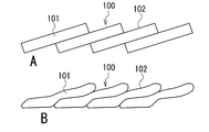
- FIG. 9 is a cross-sectional view showing an example of the sealing layer 100 formed by a conventional tire manufacturing method, and shows a cross-sectional shape in the width direction of the sealant 101 disposed on the inner surface of the tire.
- FIG. 9A schematically shows how the sealant 101 is arranged
- FIG. 9B shows a cross-sectional shape of the sealant 101 after the arrangement.
- the cross-section of the sealant 101 is formed in a rectangular shape. Further, a part of the sealant 101 is sequentially stacked, and the strip-like sealant 101 is spirally arranged on the inner surface of the tire (see FIG. 9A).
- the sealing agent 101 is affixed on the inner surface of the tire, and the sealing layer 100 is formed by the sealing agent 101.
- the sealant 101 When the sealant 101 is disposed on the inner surface of the tire (see FIG. 9B), the soft sealant 101 is deformed. As a result, the sealing agents 101 and the sealing agent 101 and the inner surface of the tire are in close contact with each other, and the sealing performance of the sealing layer 100 is exhibited. However, when the sealing agents 101 overlap with each other, the thickness of the sealing layer 100 tends to be uneven. As a result, the thickness of the sealing layer 100 may change on the inner surface of the tire, and the unevenness of the surface 102 of the sealing layer 100 may increase.
- the sealing layer 100 In order to ensure the sealing performance required for the sealing layer 100, it is necessary to form the sealing layer 100 with a thickness equal to or greater than the minimum thickness. By increasing the thickness of the sealing agent 101, the thickness of the sealing layer 100 can be ensured with the entire sealing layer 100 including a relatively thin portion. However, as the sealant 101 becomes thicker, the amount of the sealant 101 increases and the weight of the tire increases. In this regard, in the conventional tire manufacturing method, a change in the thickness of the sealing layer 100 cannot be easily suppressed, and it is difficult to make the sealing agent 101 thin.
- the present invention has been made in view of the above-described conventional problems, and an object thereof is to easily suppress a change in the thickness of the sealing layer when the sealing layer is formed on the inner surface of the tire with a strip-shaped sealing agent. is there.
- the present invention is a tire manufacturing method in which a sealing layer is formed on a tire inner surface with a strip-shaped sealing agent.
- a pair of side surfaces of the sealant located on both sides in the width direction of the sealant are inclined to the same side in the width direction of the sealant with respect to the thickness direction of the sealant.
- the sealant is spirally arranged on the inner surface of the tire to form a seal layer.
- the sealing layer when the sealing layer is formed on the inner surface of the tire by the strip-shaped sealing agent, the change in the thickness of the sealing layer can be easily suppressed.
- a tire having a sealing layer is manufactured by forming a sealing layer on the inner surface of the tire with a strip-like sealing agent (sealant). Accordingly, the tire is a self-sealing tire (sealant tire) and is mounted on various vehicle rims.
- the tire is a tubeless pneumatic tire, and is used in a state where the inside is filled with air.
- FIG. 1 is a cross-sectional view in the tire width direction F of the tire 1 of the present embodiment.
- the tire 1 is formed in a known structure by a plurality of tire constituent members.
- the tire 1 includes an annular tread portion 2 that is in contact with the road surface, a pair of bead portions 3 that are located inside the tire radial direction S of the tread portion 2, an end portion of the tread portion 2, and a bead portion 3.
- a pair of sidewall portions 4 located between the two are provided.
- the tire 1 also includes a carcass 10, an inner liner 11, a belt 12, a belt reinforcing layer 13, a bead core 14, a bead filler 15, a tread rubber 16, and a sealing layer 17.
- Various tread patterns are formed on the tread rubber 16.
- the sealing layer 17 is formed on the inner surface 5 of the tire 1 by the strip-shaped sealing agent 20, and the tire 1 is manufactured.
- the sealant 20 has a sealing performance with respect to the through hole, and automatically seals the through hole of the tire 1 when a through hole is generated by a nail or the like in a portion where the sealing layer 17 of the tire 1 is formed. As a result, air leakage from the tire 1 is prevented, and puncture of the tire 1 is suppressed.
- the strip-shaped sealing agent 20 is disposed along the tire circumferential direction on the inner surface 5 of the tire 1 while being gradually displaced in the tire width direction F (the width direction H of the sealing agent 20).
- the sealant 20 is spirally disposed on the inner surface 5 of the tire 1 and is juxtaposed in the tire width direction F.
- the sealant 20 has adhesiveness and is attached to the inner surface 5 of the tire 1 by being disposed on the inner surface 5 of the tire 1.
- An inner liner 11 is positioned on the inner surface 5 of the tire 1, and the sealant 20 is disposed on the inner liner 11.
- the sealant 20 is attached to the inner surface 5 (inner liner 11) of the tire 1 and adheres closely to the inner surface 5 due to adhesiveness. Further, the sealant 20 adjacent in the tire width direction F is adhered and stuck together due to adhesiveness.
- the sealant 20 is continuously arranged on the inner surface 5 of the tire 1 and is arranged in parallel with the inner surface 5 of the tire 1. At least a part of the inner surface 5 of the tire 1 is covered with the sealing agent 20, and the sealing layer 17 is formed by the sealing agent 20 parallel to the inner surface 5 of the tire 1.
- the sealing layer 17 is formed on the inner surface 5 of the tire 1 including at least the inner surface of the tread portion 2.
- the sealing agent 20 is disposed only on the inner surface of the tread portion 2, and the sealing layer 17 is formed only on the inner surface of the tread portion 2.
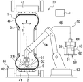
- FIG. 2 is a configuration diagram of the tire manufacturing apparatus 30 of the present embodiment, and schematically shows a part of the tire manufacturing apparatus 30.
- the tire 1 arranged in the tire manufacturing apparatus 30 is cut, and a cross section in the tire width direction F of the tire 1 is shown.
- the tire manufacturing apparatus 30 is an apparatus for forming the sealing layer 17, and includes a rotating device 40 for the tire 1, an arrangement device 50 for the sealant 20, and a control device 31.
- the control device 31 controls the entire tire manufacturing device 30 and the forming operation of the sealing layer 17 by the tire manufacturing device 30.
- the rotating device 40 includes a plurality of rotatable cylindrical rollers 41 and a driving device 42 that rotates the rollers 41.
- the plurality of rollers 41 are in contact with the tread portion 2 of the tire 1 and rotatably support the tire 1.
- the tire 1 is disposed between the plurality of rollers 41 and rotates around the axis in a state where the axis is horizontal.
- the driving device 42 is connected to one roller 41 and rotates one roller 41 by a motor (for example, a servo motor). As the roller 41 rotates, the tire 1 in contact with the roller 41 rotates.
- the rotation device 40 controls the rotation speed and rotation angle of the tire 1 to rotate the tire 1 at a predetermined speed.
- the arrangement device 50 includes a supply device 60 that supplies the sealant 20, a nozzle 51 that discharges the sealant 20, and a moving device 53 that moves the nozzle 51.
- the supply device 60 includes a container 61 that stores the sealant 20 (a material used for forming the strip-shaped sealant 20), a heating member 62 that is disposed in the container 61, and a pressurizer that pressurizes the sealant 20. 63, a supply pump 64 connected to the heating member 62, and a supply pipe 65 for the sealant 20.
- the heating member 62 is a disk-shaped platen and heats the sealant 20 in the container 61.
- the pressurizing device 63 is a piston / cylinder mechanism, and presses the heating member 62 into the container 61 to pressurize the sealant 20 in the container 61.
- the sealant 20 is sent out by the supply pump 64 while being pressurized by the pressurizing device 63.
- the supply pipe 65 is connected to the supply pump 64 and the nozzle 51.
- the sealant 20 is sent out to the nozzle 51 through the supply pipe 65 by the supply pump 64.
- the supply device 60 continuously supplies the sealant 20 to the nozzle 51.
- the nozzle 51 is a forming part for forming the strip-shaped sealant 20 and has a discharge port 52 for the sealant 20.
- the discharge port 52 is located at the tip of the nozzle 51, and the nozzle 51 discharges the sealing agent 20 supplied from the supply device 60 from the discharge port 52.
- the nozzle 51 is a die (die) that forms the sealant 20 in a predetermined cross-sectional shape, and the discharge port 52 is an opening formed in the nozzle 51.
- the sealant 20 is discharged from the discharge port 52 and formed into a cross-sectional shape corresponding to the opening shape of the discharge port 52.
- the nozzle 51 continuously discharges the sealant 20 having a predetermined cross-sectional shape from the discharge port 52 to form the strip-like sealant 20.
- the shutter of the nozzle 51 is closed, the discharge of the sealant 20 from the discharge port 52 and the formation of the sealant 20 by the nozzle 51 are stopped.
- the moving device 53 is an industrial robot having an arm 54.
- the nozzle 51 is attached to the tip of the arm 54 and moves within the movable range of the arm 54.
- the arm 54 is an articulated arm, and the moving device 53 has at least three degrees of freedom.
- the nozzle 51 is moved to an arbitrary position by the moving device 53 and arranged in an arbitrary direction and state.
- the nozzle 51 is disposed in the tire 1 by the moving device 53, and the discharge port 52 of the nozzle 51 is disposed downward.
- the moving device 53 moves the nozzle 51 in the tire 1 with the discharge port 52 facing the inner surface 5 of the tire 1.
- the nozzle 51 moves in the tire width direction F and the tire radial direction S by the moving device 53. Further, the moving device 53 changes the arrangement angle of the nozzle 51 with respect to the tire radial direction S (the discharge direction of the sealant 20 by the nozzle 51), and moves the nozzle 51 (discharge direction of the sealant 20) with respect to the tire radial direction S. And tilt.
- the nozzle 51 is moved along the inner surface 5 of the tire 1 by the moving device 53 and discharges the strip-shaped sealant 20 from the discharge port 52 toward the inner surface 5 of the tire 1.
- the vulcanized tire 1 is disposed in the rotating device 40, and the nozzle 51 is disposed in the tire 1 by the moving device 53. Further, the tire 1 is rotated by the rotating device 40, and the nozzle 51 is relatively moved along the tire circumferential direction. The nozzle 51 is disposed toward the inner surface 5 of the tire 1 and moves gradually in the tire width direction F by the moving device 53. At that time, the sealant 20 is supplied to the nozzle 51 by the supply device 60, and the sealant 20 is discharged from the discharge port 52 of the nozzle 51. The nozzle 51 forms a strip-shaped sealant 20.
- the sealant 20 is discharged from the discharge port 52 of the nozzle 51 toward the inner surface 5 of the tire 1 and is disposed spirally on the inner surface 5 of the tire 1.
- the strip-shaped sealant 20 is formed in a predetermined cross-sectional shape by the discharge port 52 of the nozzle 51 and is affixed to the inner surface 5 of the tire 1 in a spiral shape.
- the sealant 20 is arranged on the inner surface 5 of the tire 1 without a gap and is juxtaposed in a predetermined state on the inner surface 5 of the tire 1.
- the tire manufacturing apparatus 30 forms the sealing layer 17 on the inner surface 5 of the tire 1 with the sealant 20.
- the discharge of the sealing agent 20 from the discharge port 52 of the nozzle 51 is stopped.
- formation of the sealing agent 20 by the nozzle 51 is stopped, and arrangement
- the rotation of the tire 1 by the rotating device 40 is stopped, and the nozzle 51 is moved out of the tire 1 by the moving device 53.
- FIG. 3 is a cross-sectional view of the sealant 20 of the present embodiment, and the sealant 20 in a cross section (cross section orthogonal to the length direction of the sealant 20) including the width direction H and the thickness direction R of the sealant 20.
- the cross-sectional shape is shown.
- FIG. 3 is also a front view showing the discharge port 52 of the nozzle 51 and shows the opening shape of the discharge port 52 as viewed from the discharge direction of the sealant 20.
- the discharge port 52 of the nozzle 51 is formed in an opening shape corresponding to the cross-sectional shape of the sealant 20. Further, the opening size of the discharge port 52 is wider in the width direction H of the sealant 20 than in the thickness direction R of the sealant 20.
- the discharge port 52 is formed in a parallelogram shape.
- the cross section of the sealant 20 is formed in a parallelogram shape by the discharge port 52. Further, the pair of side surfaces 21 of the sealant 20 are inclined to the same side in the width direction H of the sealant 20 with respect to the thickness direction R of the sealant 20. That is, the pair of side surfaces 21 are inclined surfaces that are inclined to one side of the width direction H with respect to the thickness direction R, and are located on both sides of the sealant 20 in the width direction H (tire width direction F). Further, the pair of side surfaces 21 are formed in a smooth planar shape and are inclined at the same angle with respect to the thickness direction R.
- the strip-shaped sealant 20 includes an application surface 22 to be attached to the inner surface 5 of the tire 1, an exposed surface 23, and four corner portions (two acute angle portions 24, two obtuse angle portions). 25).
- the exposed surface 23 of the sealant 20 is a surface opposite to the pasting surface 22 and is exposed to the internal space of the tire 1.
- the affixing surface 22 and the exposed surface 23 are formed in a smooth flat shape and are located on both sides in the thickness direction R of the sealant 20.
- the side surface 21 is located between the edge of the pasting surface 22 and the edge of the exposed surface 23.
- the acute angle portion 24 and the obtuse angle portion 25 are corner portions between the side surface 21 and the pasting surface 22 (or the side surface 21 and the exposed surface 23).
- the two acute angle portions 24 are formed at an acute angle and are located at both ends of one diagonal line of the sealant 20. Further, the two acute angle portions 24 are located on the opposite sides of the sealant 20 in the width direction H and project toward the outside in the width direction H.
- the two obtuse angle portions 25 are formed at an obtuse angle and are located at both ends of the other diagonal line of the sealant 20.
- the angles of the acute angle portion 24 and the obtuse angle portion 25 are an angle formed by the side surface 21 and the pasting surface 22 and an angle formed by the side surface 21 and the exposed surface 23 in the cross section of the sealant 20.
- the angle G of the acute angle portion 24 is not less than 5 ° and not more than 15 °. Therefore, the angles of the sharp corners among the corners of the sealant 20 are all 5 ° or more and 15 ° or less.
- FIG. 4 is a cross-sectional view showing the sealing layer 17 formed by the sealing agent 20 of the present embodiment, and shows a cross-sectional shape in the width direction H of the sealing agent 20 disposed on the inner surface 5 of the tire 1.
- the side surfaces 21 of the adjacent sealing agents 20 are aligned and the side surfaces 21 are overlapped.
- a strip-shaped sealing agent 20 is spirally arranged on the inner surface 5 of the tire 1, and the sealing layer 17 is formed by the sealing agent 20.
- the side surfaces 21 of the sealing agent 20 adjacent to each other in the width direction H (tire width direction F) are in close contact with each other and are bonded together without any gap.
- the affixing surface 22 of the sealant 20 is adhered and adhered to the inner surface 5 of the tire 1. Moreover, the acute angle part 24 and the obtuse angle part 25 are overlap
- the sealing agent 20 is spirally arranged while the side surfaces 21 of the sealing agent 20 are sequentially stacked.
- the exposed surfaces 23 of the plurality of rows of sealants 20 are arranged so as to form the same surface and become the surface 18 of the seal layer 17.
- the surface 18 of the sealing layer 17 is exposed in the internal space of the tire 1.
- FIG. 5 is a cross-sectional view showing another example of the sealing layer 17 formed by the sealing agent 20 of the present embodiment.
- the sealing agent 20 even when the arrangement position of the sealing agent 20 is shifted in the width direction H, it is possible to suppress the unevenness on the surface 18 of the sealing layer 17 by overlapping the inclined side surfaces 21 of the sealing agent 20. . Further, for example, even if unevenness is generated on the surface 18 of the sealing layer 17 due to a change in the rotation speed of the tire 1 or a change in the moving speed of the nozzle 51, the increase in the unevenness is suppressed, and The step becomes smaller.
- the uniformity of the thickness of the sealing layer 17 can be improved while stabilizing the properties of the sealing layer 17.
- positioning speed of the sealing agent 20 can be made quick, and the formation efficiency of the sealing layer 17 can also be improved.
- the thickness T (see FIG. 4) of the strip-shaped sealant 20 is preferably 3 mm or more and 4.5 mm or less.
- the thickness T of the sealing agent 20 is less than 3 mm, the sealing performance of the sealing layer 17 may be affected.
- the thickness T of the sealant 20 is larger than 4.5 mm, there is a concern that the basic performance of the tire 1 related to the weight may be affected (increased rolling resistance, etc.) as the weight of the tire 1 increases. Due to the increase in the thickness T of the sealant 20, the cost of the sealant 20 increases, and there is a concern that the profitability of the tire 1 may be hindered.
- the sealing performance of the sealing layer 17 can be reliably ensured. Even when a relatively large through-hole is generated in the tire 1, the through-hole can be sealed with the sealant 20 without causing a break in the sealing layer 17. Even if the sealing layer 17 is cut, the sealing layer 17 can provide sufficient sealing performance. However, the sealing performance of the sealing layer 17 can be further improved by preventing the occurrence of a break.
- the breaking elongation of the sealant 20 is preferably 600% or more.
- the breaking elongation of the sealant 20 is a value (elongation at break) measured in accordance with JIS standards (JIS K6251).
- the original length of the test piece of the sealant 20 is L1
- the length of the test piece when the test piece is broken by the tensile test is L2.
- the breaking elongation of the sealant 20 is a ratio of L2 to L1 ((L2 / L1) ⁇ 100).
- the breaking elongation of the sealing agent 20 When the breaking elongation of the sealing agent 20 is less than 600%, the sealing performance of the sealing layer 17 may be affected. On the other hand, when the breaking elongation of the sealing agent 20 is 600% or more, the sealing performance of the sealing layer 17 can be reliably ensured. Even when a relatively large through-hole is generated in the tire 1, the through-hole can be sealed with the sealant 20 without causing a break in the sealing layer 17. Moreover, it is preferable that the breaking elongation of the sealing agent 20 is, for example, 1500% or less.
- the angle G (see FIG. 3) of the acute angle portion 24 of the sealant 20 is preferably 5 ° or more and 15 ° or less.
- the angle G of the acute angle portion 24 is less than 5 °, it becomes difficult to form the acute angle portion 24 in the sealant 20.
- the flow of the sealant 20 is stagnated at a portion corresponding to the acute angle portion 24 of the discharge port 52 of the nozzle 51, and there is a possibility that a break may occur in the acute angle portion 24.
- the angle G of the acute angle portion 24 is larger than 15 °, the width of the side surface 21 of the sealant 20 is shortened, and the contact area between the side surfaces 21 may be reduced.
- the angle G of the acute angle portion 24 of the sealant 20 is 5 ° or more and 15 ° or less, the acute angle portion 24 of the sealant 20 can be formed smoothly and the side surfaces 21 can be more closely adhered to each other. it can.
- the tire manufacturing device 30 (see FIG. 2) is provided with two placement devices 50, and the two placement devices 50 remove the two strip-like sealants 20 from the inner surface of the tire 1.
- 5 may be arranged simultaneously.
- the inner surface 5 of the tire 1 is divided in half in the tire width direction F, and the two sealants 20 are respectively disposed on the half portions of the inner surface 5.
- positioning of the two sealing agents 20 is started from two places of the inner surface 5, and the two sealing agents 20 are arranged helically on the inner surface 5, respectively.
- one sealant 20 is disposed from one end portion of the tread portion 2 in the tire width direction F toward the tire equator, and the other sealant 20 is disposed from the other end portion of the tread portion 2 in the tire width direction F to the tire equator. Place towards the.
- one sealant 20 is disposed from one end of the tread portion 2 in the tire width direction F toward the tire equator, and the other sealant 20 is disposed from the tire equator to the other end of the tread portion 2 in the tire width direction F. Arrange towards.
- one strip-shaped sealant 20 may be arranged on the inner surface 5 of the tire 1 by one arrangement device 50.
- the sealant 20 is disposed from one end portion in the tire width direction F of the tread portion 2 toward the other end portion.
- the sealing layer 17 may be formed using the sealing agent 20 formed in a strip shape in advance.
- the exposed surface 23 of the sealant 20 is attached to a strip-shaped film, or the exposed surface 23 of the sealant 20 is coated with a coating material (such as powder).
- the sealing agent 20 is spirally disposed on the inner surface 5 of the tire 1 while the affixing surface 22 of the sealing agent 20 is attached to the inner surface 5 of the tire 1.
- the front end portion and the rear end portion of the sealant 20 can be arranged on the inner surface 5 of the tire 1 at an arbitrary position in the tire circumferential direction. Further, in order to reduce the cavity resonance sound of the tire 1, a porous member (for example, a sponge) may be disposed on the surface 18 of the sealing layer 17 using the adhesiveness of the sealing agent 20.
- the sealing layer 17 may be formed on the inner surface 5 of the tire 1 other than the tread portion 2 in addition to the inner surface of the tread portion 2.
- the tire 1 forming the sealing layer 17 may be a passenger car tire or other tires (for example, truck tires, truck / bus tires, two-wheeled vehicle tires).
- the tire 1 may be vulcanized after the sealing layer 17 is formed on the inner surface 5 of the tire 1 before vulcanization.
- the sealant 20 is a rubber composition in which various compounding components (plasticizer, reinforcing filler, etc.) are compounded with the rubber component.
- the sealant 20 includes at least one of butyl rubber and ethylene / propylene / diene rubber (EPDM) as a rubber component.
- the butyl rubber is, for example, a halogenated butyl rubber.
- the rubber component of the sealant 20 is blended with zinc oxide, thiuram vulcanization accelerator, and a plasticizer (here, liquid polybutene or process oil).
- the thiuram vulcanization accelerator is preferably 4 parts by mass or less, and the zinc oxide is preferably 5 parts by mass or less. Tetrabenzylthiuram disulfide is preferably used as the thiuram vulcanization accelerator.
- the thiuram vulcanization accelerator acts efficiently by zinc oxide, and the fluidity or sticking property of the sealant 20 is adjusted by the blending amount of the thiuram vulcanization accelerator and zinc oxide.
- the sealant 20 is blended with a thermoplastic resin (such as a rosin resin, a terpene resin, or a petroleum resin) that is an adhesive.
- a thermoplastic resin such as a rosin resin, a terpene resin, or a petroleum resin
- the sealant 20 can be blended with various blending components (reinforcing fillers, stearic acid, anti-aging agents, etc.) blended in ordinary rubber compositions. .
- the rubber composition (sealing agent 20) after blending is kneaded by a kneader.
- the sealant 20 may be vulcanized during the kneading.
- the sealing agent 20 during kneading is preferably heated to 110 to 140 ° C., more preferably the sealing agent 20 is heated to 120 to 135 ° C.
- the plasticizer is prevented from volatilizing.
- the seal layer 17 was formed on the inner surface 5 of the tire 1 with the sealant 20 (referred to as an example).
- the sealing layer 100 was formed in the inner surface 5 of the tire 1 with the conventional sealing agent 101 (refer FIG. 9) (it is called a prior art example).
- a sealing layer was formed on the inner surface 5 of the tire 1 with a sealing agent having a cross-sectional shape different from that of the sealing agents 20 and 101 (referred to as a comparative example).
- FIG. 6 is a cross-sectional view of a sealing agent 101 of a conventional example
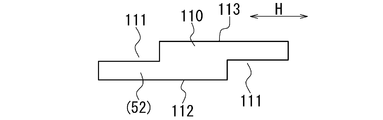
- FIG. 7 is a cross-sectional view of a sealing agent 110 of a comparative example.
- 6 and 7 show the opening shapes of the discharge ports 52 of the nozzles 51 that form the sealing agents 101 and 110, respectively.
- the sealing agents 101 and 110 are discharged from the discharge port 52 and formed in a cross-sectional shape corresponding to the opening shape of the discharge port 52.
- the cross-section of the sealant 101 is formed in a rectangular shape. With a portion of the sealant 101 overlapped, the sealant 101 was spirally disposed on the inner surface 5 of the tire 1 to form a conventional sealing layer 100 (see FIG. 9).
- the cross section of the sealant 110 was formed into a bent shape having two step portions 111.
- the two step portions 111 are located on opposite sides of the sealant 110 in the width direction H, and are formed on the sticking surface 112 side and the exposed surface 113 side of the sealant 110, respectively.
- the two step portions 111 are formed to have the same width and the same depth (step).
- the thickness of the sealant 110 in the portion where the step 111 is formed is half the thickness of the sealant 110 in the portion other than the step 111.
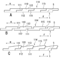
- FIG. 8 is a cross-sectional view showing the sealing layer 114 formed by the sealing agent 110 of the comparative example.
- the sealing layer 114 when the sealing layer 114 is formed, the positions of the step portions 111 of the adjacent sealants 110 are aligned, and a part of the sealant 110 (the portion of the step portions 111) is arranged to overlap.
- a strip-shaped sealant 110 was spirally arranged on the inner surface 5 of the tire 1, and a seal layer 114 was formed by the sealant 110.
- the step portions 111 of the sealing agent 110 adjacent in the width direction H are combined, and the sealing agent 110 is juxtaposed with the inner surface 5 of the tire 1.
- the sealing layer 114 When the sealing layer 114 is formed, the lower the rotational speed of the tire 1, the easier the adjustment of the arrangement position of the sealant 110 by the arrangement device 50 (see FIG. 2).
- the step portions 111 of the sealant 110 are accurately combined to overlap each other (referred to as proper overlap). As a result, the unevenness of the surface 115 of the sealing layer 114 is reduced.
- the stepped portion 111 of the sealing agent 110 is raised, and a convex portion 117 is generated on the surface 115 of the sealing layer 114 (referred to as wide overlapping).
- a convex portion 117 is generated on the surface 115 of the sealing layer 114 (referred to as wide overlapping).
- the tire 1 was rotated at a predetermined rotation speed by the rotating device 40, and the strip-shaped sealing agents 20, 101, and 110 were disposed on the inner surface 5 of the tire 1.
- the rotation speed of the tire 1 is the arrangement speed of the sealants 20, 101, 110. The higher the rotation speed of the tire 1, the easier the displacement position of the sealants 20, 101, 110 shifts in the width direction H.
- the rotational speed of the tire 1 in the example is 100
- the conventional example the rotational speed of the tire 1 is 50
- the tire 1 is rotated at a rotational speed that is half the rotational speed in the example.
- the rotation speed of the tire 1 was 100 and 50, and the tire 1 was rotated at each rotation speed.
- the change (variation) in the thickness of the sealing layers 17, 100, 114 was determined, and the properties of the sealing layers 17, 100, 114 were investigated.
- the shape of the inner surface 5 of the tire 1 is previously detected by a detection sensor (for example, a laser sensor, a 2D sensor) before the sealing layers 17, 100, 114 are formed. did.
- the shape of the inner surface 5 for one turn of the tire 1 was detected, and the detected shape was recorded.
- the shapes of the surfaces 18, 102, 115 of the sealing layers 17, 100, 114 for one turn of the tire 1 were detected, and the detected shapes were recorded.
- the difference between the shape of the surfaces 18, 102, 115 of the sealing layers 17, 100, 114 and the shape of the inner surface 5 of the tire 1 was calculated, and the thickness of each part of the sealing layers 17, 100, 114 was measured.
- the side constant of the thickness of the sealing layers 17, 100, 114 was determined based on the size of the tire 1, the width of the sealing layers 17, 100, 114, and the like. Here, 200,000 or more thicknesses were measured, and thickness range R and thickness standard deviation ⁇ were calculated.
- the thickness range R is a difference between the maximum thickness value and the minimum thickness value (maximum value ⁇ minimum value). It shows that the change of the thickness of the sealing layers 17, 100, 114 is so small that the range R of thickness and the standard deviation (sigma) of thickness are small. Therefore, as the thickness range R and the standard deviation ⁇ of the thickness are smaller, the unevenness of the surfaces 18, 102, 115 of the sealing layers 17, 100, 114 is smaller, and the properties of the sealing layers 17, 100, 114 are better. Show.
- Table 1 shows the results of the formation test of the sealing layers 17, 100 and 114.
- the thickness range R was 3.3, and the standard deviation ⁇ of the thickness was 0.70.
- the thickness range R (1.1) and the standard deviation ⁇ (0.29) of the thickness were smaller than those of the conventional example.
- the sealant 110 when the rotational speed of the tire 1 was increased, it was difficult to adjust the arrangement position of the sealant 110, and the sealant 110 had a narrow overlap and a wide overlap.
- the thickness range R (2.8) and the thickness standard deviation ⁇ (0.48) were larger than the proper overlap.
- the thickness range R (3.3) and the thickness standard deviation ⁇ (0.58) were larger than the proper overlap.
- the thickness range R (2.2) and the standard deviation ⁇ (0.36) of the thickness were smaller than the conventional example. From this, it was found that in the example, the change in the thickness of the sealing layer 17 can be suppressed and the properties of the sealing layer 17 can be improved.
Landscapes
- Engineering & Computer Science (AREA)
- Mechanical Engineering (AREA)
- Tires In General (AREA)
- Tyre Moulding (AREA)
Abstract
タイヤの内面にストリップ状の密封剤により密封層を形成するときに、密封層の厚みの変化を容易に抑制する。 ストリップ状の密封剤(20)により、タイヤ(1)の内面(5)に密封層(17)を形成する。密封剤(20)の一対の側面(21)は、密封剤(20)の幅方向(H)の両側に位置し、密封剤(20)の厚み方向(R)に対して、密封剤(20)の幅方向(H)の同じ側に傾斜する。隣り合う密封剤(20)の側面(21)同士を重ねた状態で、タイヤ(1)の内面(5)に密封剤(20)を螺旋状に配置して、密封層(17)を形成する。
Description
本発明は、タイヤの内面に密封層を形成するタイヤ製造方法に関する。
セルフシールタイヤ(又は、シーラントタイヤ)と呼ばれるタイヤでは、密封剤により、タイヤの内面に密封層が形成されている。タイヤに貫通孔が生じたときには、密封剤により貫通孔が自動的に密封されて、タイヤからの空気の漏れが防止される。このようなタイヤの製造方法として、従来、ストリップ状の密封剤をタイヤの内面に螺旋状に貼り付けて密封層を形成する製造方法が知られている(特許文献1参照)。
図9は、従来のタイヤ製造方法により形成された密封層100の例を示す断面図であり、タイヤの内面に配置された密封剤101の幅方向の断面形状を示している。図9Aは、密封剤101の配置の仕方を模式的に示しており、図9Bは、配置後の密封剤101の断面形状を示している。
図示のように、従来の一般的なタイヤ製造方法では、密封剤101の断面は、矩形状に形成される。また、密封剤101の一部を順に重ねて、ストリップ状の密封剤101をタイヤの内面に螺旋状に配置する(図9A参照)。これにより、タイヤの内面に密封剤101を貼り付けて、密封剤101により密封層100を形成する。
図示のように、従来の一般的なタイヤ製造方法では、密封剤101の断面は、矩形状に形成される。また、密封剤101の一部を順に重ねて、ストリップ状の密封剤101をタイヤの内面に螺旋状に配置する(図9A参照)。これにより、タイヤの内面に密封剤101を貼り付けて、密封剤101により密封層100を形成する。
密封剤101をタイヤの内面に配置すると(図9B参照)、軟らかい密封剤101が変形する。その結果、密封剤101同士、及び、密封剤101とタイヤの内面が密着して、密封層100の密封性能が発揮される。ところが、密封剤101同士が重なることで、密封層100の厚みが不均一になり易い。これに伴い、タイヤの内面で、密封層100の厚みが変化して、密封層100の表面102の凹凸が大きくなる虞がある。
密封層100に要求される密封性能を確保するためには、密封層100を最小厚み以上の厚みに形成する必要がある。密封剤101の厚みを増すことで、相対的に薄い部分を含む密封層100の全体で、密封層100の厚みを確保することができる。しかしながら、密封剤101が厚くなるほど、密封剤101の量が増加して、タイヤの重量が増加する。この点に関し、従来のタイヤ製造方法では、密封層100の厚みの変化を容易には抑制できず、密封剤101を薄くするのが難しい。
本発明は、前記従来の問題に鑑みなされたもので、その目的は、タイヤの内面にストリップ状の密封剤により密封層を形成するときに、密封層の厚みの変化を容易に抑制することである。
本発明は、タイヤの内面に、ストリップ状の密封剤により密封層を形成するタイヤ製造方法である。密封剤の幅方向の両側に位置する密封剤の一対の側面は、密封剤の厚み方向に対して、密封剤の幅方向の同じ側に傾斜する。隣り合う密封剤の側面同士を重ねた状態で、タイヤの内面に密封剤を螺旋状に配置して、密封層を形成する。
本発明によれば、タイヤの内面にストリップ状の密封剤により密封層を形成するときに、密封層の厚みの変化を容易に抑制することができる。
本発明のタイヤ製造方法の一実施形態について、図面を参照して説明する。
本実施形態のタイヤ製造方法では、タイヤの内面に、ストリップ状の密封剤(シーラント)により密封層を形成して、密封層を有するタイヤを製造する。従って、タイヤは、セルフシールタイヤ(シーラントタイヤ)であり、種々の車両のリムに装着される。また、タイヤは、チューブレスの空気入りタイヤであり、内部に空気が充填された状態で使用される。
本実施形態のタイヤ製造方法では、タイヤの内面に、ストリップ状の密封剤(シーラント)により密封層を形成して、密封層を有するタイヤを製造する。従って、タイヤは、セルフシールタイヤ(シーラントタイヤ)であり、種々の車両のリムに装着される。また、タイヤは、チューブレスの空気入りタイヤであり、内部に空気が充填された状態で使用される。
図1は、本実施形態のタイヤ1のタイヤ幅方向Fの断面図である。
図示のように、タイヤ1は、複数のタイヤ構成部材により、周知の構造に形成される。具体的には、タイヤ1は、路面に接地する環状のトレッド部2と、トレッド部2のタイヤ半径方向Sの内側に位置する一対のビード部3と、トレッド部2の端部とビード部3の間に位置する一対のサイドウォール部4を備えている。また、タイヤ1は、カーカス10、インナーライナ11、ベルト12、ベルト補強層13、ビードコア14、ビードフィラ15、トレッドゴム16、及び、密封層17を備えている。トレッドゴム16には、種々のトレッドパターンが形成される。
図示のように、タイヤ1は、複数のタイヤ構成部材により、周知の構造に形成される。具体的には、タイヤ1は、路面に接地する環状のトレッド部2と、トレッド部2のタイヤ半径方向Sの内側に位置する一対のビード部3と、トレッド部2の端部とビード部3の間に位置する一対のサイドウォール部4を備えている。また、タイヤ1は、カーカス10、インナーライナ11、ベルト12、ベルト補強層13、ビードコア14、ビードフィラ15、トレッドゴム16、及び、密封層17を備えている。トレッドゴム16には、種々のトレッドパターンが形成される。
生タイヤの加硫後に、ストリップ状の密封剤20により、密封層17がタイヤ1の内面5に形成されて、タイヤ1が製造される。密封剤20は、貫通孔に対する密封性能を有しており、タイヤ1の密封層17の形成部分に釘等により貫通孔が生じたときに、タイヤ1の貫通孔を自動的に密封する。これにより、タイヤ1からの空気の漏れが防止されて、タイヤ1のパンクが抑制される。
密封層17の形成時には、ストリップ状の密封剤20を、タイヤ幅方向F(密封剤20の幅方向H)に次第に変位させつつ、タイヤ1の内面5にタイヤ周方向に沿って配置する。これにより、密封剤20が、タイヤ1の内面5に螺旋状に配置されて、タイヤ幅方向Fに並列する。密封剤20は、粘着性を有しており、タイヤ1の内面5への配置により、タイヤ1の内面5に貼り付けられる。タイヤ1の内面5にはインナーライナ11が位置しており、密封剤20はインナーライナ11に配置される。密封剤20は、粘着性により、タイヤ1の内面5(インナーライナ11)に貼り付けられて、内面5に密着する。また、タイヤ幅方向Fに隣り合う密封剤20は、粘着性により、互いに密着して貼り合わされる。
密封剤20は、タイヤ1の内面5に連続して配置されて、タイヤ1の内面5に並列する。密封剤20により、タイヤ1の内面5の少なくとも一部が覆われて、タイヤ1の内面5に並列する密封剤20により、密封層17が形成される。密封層17は、少なくともトレッド部2の内面を含むタイヤ1の内面5に形成される。ここでは、密封剤20がトレッド部2の内面のみに配置されて、密封層17がトレッド部2の内面のみに形成される。
図2は、本実施形態のタイヤ製造装置30の構成図であり、タイヤ製造装置30の一部を模式的に示している。また、図2では、タイヤ製造装置30に配置されたタイヤ1を切断して、タイヤ1のタイヤ幅方向Fの断面を示している。
図示のように、タイヤ製造装置30は、密封層17の形成装置であり、タイヤ1の回転装置40と、密封剤20の配置装置50と、制御装置31を備えている。制御装置31は、タイヤ製造装置30の全体、及び、タイヤ製造装置30による密封層17の形成動作を制御する。
図示のように、タイヤ製造装置30は、密封層17の形成装置であり、タイヤ1の回転装置40と、密封剤20の配置装置50と、制御装置31を備えている。制御装置31は、タイヤ製造装置30の全体、及び、タイヤ製造装置30による密封層17の形成動作を制御する。
回転装置40は、回転可能な複数の円筒状のローラ41と、ローラ41を回転させる駆動装置42を有する。複数のローラ41は、タイヤ1のトレッド部2に接触して、タイヤ1を回転可能に支持する。タイヤ1は、複数のローラ41の間に配置されて、軸線を水平にした状態で、軸線周りに回転する。駆動装置42は、1つのローラ41に連結され、モータ(例えば、サーボモータ)により、1つのローラ41を回転させる。ローラ41の回転に伴い、ローラ41に接触するタイヤ1が回転する。回転装置40は、タイヤ1の回転速度と回転角度を制御して、タイヤ1を所定速度で回転させる。
配置装置50は、密封剤20を供給する供給装置60と、密封剤20を吐き出すノズル51と、ノズル51を移動させる移動装置53を有する。供給装置60は、密封剤20(ストリップ状の密封剤20の形成に用いられる材料)を収容する容器61と、容器61内に配置される加熱部材62と、密封剤20を加圧する加圧装置63と、加熱部材62に接続された供給ポンプ64と、密封剤20の供給管65を有する。
加熱部材62は、円盤状のプラテンであり、容器61内の密封剤20を加熱する。加圧装置63は、ピストン・シリンダ機構であり、加熱部材62を容器61内に押し込んで、容器61内の密封剤20を加圧する。密封剤20は、加圧装置63により加圧された状態で、供給ポンプ64により送り出される。供給管65は、供給ポンプ64とノズル51に接続されている。供給ポンプ64により、密封剤20は、供給管65を通してノズル51に送り出される。供給装置60は、密封剤20をノズル51に連続して供給する。
ノズル51は、ストリップ状の密封剤20を形成する形成部であり、密封剤20の吐出口52を有する。吐出口52は、ノズル51の先端に位置しており、ノズル51は、供給装置60から供給された密封剤20を吐出口52から吐き出す。また、ノズル51は、密封剤20を所定の断面形状に形成するダイ(口金)であり、吐出口52は、ノズル51に形成された開口部である。
ノズル51に設けられたシャッターが開くことで、密封剤20が、吐出口52から吐き出されて、吐出口52の開口形状に対応した断面形状に形成される。ノズル51は、吐出口52から所定の断面形状の密封剤20を連続して吐き出して、ストリップ状の密封剤20を形成する。ノズル51のシャッターが閉じることで、吐出口52からの密封剤20の吐き出し、及び、ノズル51による密封剤20の形成が停止する。
移動装置53は、アーム54を有する産業用ロボットである。ノズル51は、アーム54の先端に取り付けられて、アーム54の可動範囲内で移動する。アーム54は、多関節アームであり、移動装置53は、少なくとも3軸の自由度を有する。移動装置53により、ノズル51は、任意の位置に移動して、任意の向き及び状態に配置される。移動装置53により、ノズル51がタイヤ1内に配置されて、ノズル51の吐出口52が下方に向けて配置される。移動装置53は、吐出口52がタイヤ1の内面5に対向する状態で、ノズル51をタイヤ1内で移動させる。
移動装置53により、ノズル51は、タイヤ幅方向Fとタイヤ半径方向Sに移動する。また、移動装置53は、タイヤ半径方向Sに対するノズル51の配置角度(ノズル51による密封剤20の吐出方向)を変更して、ノズル51(密封剤20の吐出方向)をタイヤ半径方向Sに対して傾斜させる。ノズル51は、移動装置53により、タイヤ1の内面5に沿って移動して、吐出口52からタイヤ1の内面5に向かってストリップ状の密封剤20を吐き出す。
タイヤ製造装置30によるタイヤ1の製造時には、加硫済みのタイヤ1を回転装置40に配置し、移動装置53により、ノズル51をタイヤ1内に配置する。また、回転装置40により、タイヤ1を回転させて、ノズル51をタイヤ周方向に沿って相対的に移動させる。移動装置53により、ノズル51は、タイヤ1の内面5に向けて配置されて、タイヤ幅方向Fに次第に移動する。その際、供給装置60により、密封剤20をノズル51に供給し、ノズル51の吐出口52から密封剤20を吐き出す。ノズル51により、ストリップ状の密封剤20が形成される。
密封剤20は、ノズル51の吐出口52からタイヤ1の内面5に向かって吐き出されて、タイヤ1の内面5に螺旋状に配置される。ストリップ状の密封剤20は、ノズル51の吐出口52により所定の断面形状に形成されて、タイヤ1の内面5に螺旋状に貼り付けられる。タイヤ製造装置30により、密封剤20は、タイヤ1の内面5に隙間なく配置されて、タイヤ1の内面5に所定の状態で並列する。
タイヤ製造装置30は、密封剤20により、タイヤ1の内面5に密封層17を形成する。密封層17の形成が完了したときに、ノズル51の吐出口52からの密封剤20の吐き出しを停止する。これにより、ノズル51による密封剤20の形成を停止して、密封剤20のタイヤ1の内面5への配置を終了する。その後、回転装置40によるタイヤ1の回転を停止し、移動装置53により、ノズル51をタイヤ1外に移動させる。
図3は、本実施形態の密封剤20の断面図であり、密封剤20の幅方向Hと厚み方向Rとを含む断面(密封剤20の長さ方向に直交する断面)における密封剤20の断面形状を示している。また、図3は、ノズル51の吐出口52を示す正面図でもあり、密封剤20の吐出方向からみた吐出口52の開口形状を示している。
図示のように、ノズル51の吐出口52は、密封剤20の断面形状に対応した開口形状に形成されている。また、吐出口52の開口寸法は、密封剤20の厚み方向Rよりも密封剤20の幅方向Hに広くなっている。ここでは、吐出口52は、平行四辺形状に形成されている。
図示のように、ノズル51の吐出口52は、密封剤20の断面形状に対応した開口形状に形成されている。また、吐出口52の開口寸法は、密封剤20の厚み方向Rよりも密封剤20の幅方向Hに広くなっている。ここでは、吐出口52は、平行四辺形状に形成されている。
密封剤20の幅方向Hと厚み方向Rとを含む断面において、密封剤20の断面は、吐出口52により、平行四辺形状に形成される。また、密封剤20の一対の側面21は、密封剤20の厚み方向Rに対して、密封剤20の幅方向Hの同じ側に傾斜する。即ち、一対の側面21は、厚み方向Rに対して幅方向Hの一方側に傾斜する傾斜面であり、密封剤20の幅方向H(タイヤ幅方向F)の両側に位置する。また、一対の側面21は、平滑な平面状に形成され、厚み方向Rに対して、互いに同じ角度で傾斜する。
ストリップ状の密封剤20は、一対の側面21に加えて、タイヤ1の内面5に貼り付けられる貼付面22と、露出面23と、4つの角部(2つの鋭角部24、2つの鈍角部25)を有する。密封剤20の露出面23は、貼付面22の反対側の面であり、タイヤ1の内部空間に露出する。貼付面22と露出面23は、平滑な平面状に形成され、密封剤20の厚み方向Rの両側に位置する。側面21は、貼付面22の縁部と露出面23の縁部の間に位置する。鋭角部24と鈍角部25は、側面21と貼付面22(又は、側面21と露出面23)の間の角部である。
密封剤20の断面において、2つの鋭角部24は、鋭角に形成されて、密封剤20の一方の対角線の両端部に位置する。また、2つの鋭角部24は、互いに密封剤20の幅方向Hの反対側に位置し、幅方向Hの外側に向かって突出する。2つの鈍角部25は、鈍角に形成されて、密封剤20の他方の対角線の両端部に位置する。鋭角部24と鈍角部25の角度は、密封剤20の断面において、側面21と貼付面22のなす角度と、側面21と露出面23のなす角度である。ここでは、鋭角部24の角度Gは、5°以上15°以下である。従って、密封剤20の角部のうちの鋭角な角部の角度は、全て、5°以上15°以下である。
図4は、本実施形態の密封剤20により形成された密封層17を示す断面図であり、タイヤ1の内面5に配置された密封剤20の幅方向Hの断面形状を示している。
図示のように、密封層17の形成時には、隣り合う密封剤20の側面21の位置を合わせて、側面21を重ねて配置する。側面21同士を重ねた状態で、タイヤ1の内面5にストリップ状の密封剤20を螺旋状に配置して、密封剤20により密封層17を形成する。密封層17内で、幅方向H(タイヤ幅方向F)に隣り合う密封剤20の側面21は、互いに密着して、隙間なく貼り合わされる。
図示のように、密封層17の形成時には、隣り合う密封剤20の側面21の位置を合わせて、側面21を重ねて配置する。側面21同士を重ねた状態で、タイヤ1の内面5にストリップ状の密封剤20を螺旋状に配置して、密封剤20により密封層17を形成する。密封層17内で、幅方向H(タイヤ幅方向F)に隣り合う密封剤20の側面21は、互いに密着して、隙間なく貼り合わされる。
密封剤20の貼付面22は、タイヤ1の内面5に密着して貼り付けられる。また、貼付面22側と露出面23側のそれぞれにおいて、隣り合う密封剤20の鋭角部24の位置と鈍角部25の位置を合わせて、鋭角部24と鈍角部25を重ねて配置する。その状態で、密封剤20の側面21同士を順に重ねつつ、密封剤20を螺旋状に配置する。これにより、複数列の密封剤20の露出面23が、同一面をなすように配置されて、密封層17の表面18となる。密封層17の表面18は、タイヤ1の内部空間に露出する。
図5は、本実施形態の密封剤20により形成された密封層17の他の例を示す断面図である。
図示のように、密封剤20の配置位置が幅方向Hにずれたときでも、密封剤20の傾斜した側面21同士を重ねることで、密封層17の表面18に凹凸が生じるのが抑制される。また、例えば、タイヤ1の回転速度の変化、又は、ノズル51の移動速度の変化により、密封層17の表面18に凹凸が生じたとしても、凹凸が大きくなるのが抑制されて、表面18の段差が小さくなる。
図示のように、密封剤20の配置位置が幅方向Hにずれたときでも、密封剤20の傾斜した側面21同士を重ねることで、密封層17の表面18に凹凸が生じるのが抑制される。また、例えば、タイヤ1の回転速度の変化、又は、ノズル51の移動速度の変化により、密封層17の表面18に凹凸が生じたとしても、凹凸が大きくなるのが抑制されて、表面18の段差が小さくなる。
以上説明したように、本実施形態のタイヤ製造方法では、タイヤ1の内面5に形成される密封層17の厚みの変化を容易に抑制することができる。その結果、密封層17の性状を安定させつつ、密封層17の厚みの均一性を向上させることができる。また、密封剤20の配置速度を速くして、密封層17の形成効率を向上させることもできる。
ストリップ状の密封剤20の厚みT(図4参照)は、3mm以上4.5mm以下であるのが好ましい。密封剤20の厚みTが3mm未満であるときには、密封層17の密封性能に影響が生じる虞がある。また、密封剤20の厚みTが4.5mmより大きいときには、タイヤ1の重量増加に伴い、重量に関係するタイヤ1の基本性能に影響(転がり抵抗の増加等)が生じることが懸念される。密封剤20の厚みTの増加により、密封剤20の費用が高くなり、タイヤ1の採算性に支障を来すことも懸念される。
これに対し、密封剤20の厚みTが3mm以上4.5mm以下であるときには、密封層17の密封性能を確実に確保することができる。比較的大きな貫通孔がタイヤ1に生じたときでも、密封層17に切れ目が生じることなく、密封剤20により貫通孔を密封することができる。密封層17に切れ目が生じたとしても、密封層17により充分な密封性能が得られる。ただし、切れ目が生じるのを防止することで、密封層17の密封性能を、より向上させることができる。
密封剤20の破断伸度は、600%以上であるのが好ましい。ここでは、密封剤20の破断伸度は、JIS規格(JIS K6251)に準拠して測定した値(破断時伸び)である。密封剤20の試験片の元の長さをL1、引張試験により試験片が破断したときの試験片の長さをL2とする。この場合に、密封剤20の破断伸度は、L1に対するL2の比率((L2/L1)×100)である。
密封剤20の破断伸度が600%未満であるときには、密封層17の密封性能に影響が生じる虞がある。これに対し、密封剤20の破断伸度が600%以上であるときには、密封層17の密封性能を確実に確保することができる。比較的大きな貫通孔がタイヤ1に生じたときでも、密封層17に切れ目が生じることなく、密封剤20により貫通孔を密封することができる。また、密封剤20の破断伸度は、例えば、1500%以下であるのが好ましい。
密封剤20の鋭角部24の角度G(図3参照)は、5°以上15°以下であるのが好ましい。鋭角部24の角度Gが5°未満であるときには、密封剤20に鋭角部24を形成し難くなる。また、ノズル51の吐出口52の鋭角部24に対応する部分で、密封剤20の流れが滞り、鋭角部24に切れ目が生じる虞がある。鋭角部24の角度Gが15°より大きいときには、密封剤20の側面21の幅が短くなり、側面21同士の密着面積が減少する虞がある。これに対し、密封剤20の鋭角部24の角度Gが5°以上15°以下であるときには、密封剤20の鋭角部24を円滑に形成できるとともに、側面21同士をより確実に密着させることができる。
密封層17の形成時間を短縮するため、タイヤ製造装置30(図2参照)に2つの配置装置50を設けて、2つの配置装置50により、2つのストリップ状の密封剤20をタイヤ1の内面5に同時に配置してもよい。この場合には、タイヤ1の内面5をタイヤ幅方向Fに半分に分けて、2つの密封剤20をそれぞれ内面5の半分の部分に配置する。また、2つの密封剤20の配置を内面5の2箇所から開始して、2つの密封剤20をそれぞれ内面5に螺旋状に配置する。その際、一方の密封剤20をトレッド部2のタイヤ幅方向Fの一端部からタイヤ赤道に向かって配置し、他方の密封剤20をトレッド部2のタイヤ幅方向Fの他端部からタイヤ赤道に向かって配置する。或いは、一方の密封剤20をトレッド部2のタイヤ幅方向Fの一端部からタイヤ赤道に向かって配置し、他方の密封剤20をタイヤ赤道からトレッド部2のタイヤ幅方向Fの他端部に向かって配置する。
これに対し、1つの配置装置50により、1つのストリップ状の密封剤20をタイヤ1の内面5に配置してもよい。この場合には、密封剤20をトレッド部2のタイヤ幅方向Fの一端部から他端部に向かって配置する。また、予めストリップ状に形成した密封剤20を用いて、密封層17を形成してもよい。この場合には、密封剤20の露出面23をストリップ状のフィルムに貼り付け、或いは、密封剤20の露出面23をコーティング材(紛体等)でコーティングする。その後、密封剤20の貼付面22をタイヤ1の内面5に貼り付けつつ、密封剤20をタイヤ1の内面5に螺旋状に配置する。
密封剤20の前端部と後端部は、タイヤ1の内面5で、タイヤ周方向の任意の位置に配置することができる。また、タイヤ1の空洞共鳴音を低減するため、密封剤20の粘着性を利用して、密封層17の表面18に多孔質部材(例えば、スポンジ)を配置してもよい。密封層17は、トレッド部2の内面に加えて、トレッド部2以外のタイヤ1の内面5に形成してもよい。密封層17を形成するタイヤ1は、乗用車用タイヤであってもよく、他のタイヤ(例えば、トラック用タイヤ、トラック・バス用タイヤ、二輪車量タイヤ)であってもよい。加硫前のタイヤ1の内面5に密封層17を形成した後に、タイヤ1を加硫するようにしてもよい。
密封剤20としては、密封層17に用いられている周知の密封剤を用いることができる。例えば、密封剤20は、ゴム成分に各種の配合成分(可塑剤、補強性充填材等)を配合したゴム組成物である。具体的には、密封剤20は、ゴム成分として、ブチルゴムとエチレン・プロピレン・ジエンゴム(EPDM)の少なくとも一方を含む。ブチルゴムは、例えば、ハロゲン化ブチルゴムである。また、密封剤20のゴム成分には、酸化亜鉛、チウラム系加硫促進剤、及び、可塑剤(ここでは、液状ポリブテン又はプロセスオイル)が配合される。
ゴム成分100質量部に対し、酸化亜鉛を2~10質量部、チウラム系加硫促進剤を1~10質量部配合する。また、チウラム系加硫促進剤と酸化亜鉛は、(チウラム系加硫促進剤:酸化亜鉛=1:1~1:3)の比を満たすように、ゴム成分に配合される。チウラム系加硫促進剤は4質量部以下であるのが好ましく、酸化亜鉛は5質量部以下であるのが好ましい。チウラム系加硫促進剤としては、テトラベンジルチウラムジスルフィドを用いるのが好ましい。酸化亜鉛によりチウラム系加硫促進剤が効率的に作用し、チウラム系加硫促進剤と酸化亜鉛の配合量により、密封剤20の流動性又は固着性が調節される。
ゴム成分100質量部に対し、150質量部以上の液状ポリブテン又はプロセスオイルを配合する。また、密封剤20には、粘着剤である熱可塑性樹脂(ロジン系樹脂、テルペン系樹脂、石油系樹脂等)が配合される。以上の基本的な配合成分に加えて、密封剤20には、通常のゴム組成物に配合される種々の配合成分(補強性充填材、ステアリン酸、老化防止剤等)を配合することができる。配合後のゴム組成物(密封剤20)は、混練機により混練される。混練中に密封剤20を加硫してもよい。この場合には、混練中の密封剤20を110~140℃に加熱するのが好ましく、密封剤20を120~135℃に加熱するのがより好ましい。密封剤20の混練を140℃以下の温度で行うことで、可塑剤の揮発が防止される。
(密封層の形成試験)
密封剤20による効果を確認するため、以上説明したように、密封剤20により、タイヤ1の内面5に密封層17を形成した(実施例という)。また、従来の密封剤101(図9参照)により、タイヤ1の内面5に密封層100を形成した(従来例という)。更に、実施例及び従来例との比較のため、密封剤20、101とは異なる断面形状の密封剤により、タイヤ1の内面5に密封層を形成した(比較例という)。
密封剤20による効果を確認するため、以上説明したように、密封剤20により、タイヤ1の内面5に密封層17を形成した(実施例という)。また、従来の密封剤101(図9参照)により、タイヤ1の内面5に密封層100を形成した(従来例という)。更に、実施例及び従来例との比較のため、密封剤20、101とは異なる断面形状の密封剤により、タイヤ1の内面5に密封層を形成した(比較例という)。
図6は、従来例の密封剤101の断面図であり、図7は、比較例の密封剤110の断面図である。また、図6、図7は、それぞれ密封剤101、110を形成するノズル51の吐出口52の開口形状を示している。
図示のように、密封剤101、110は、吐出口52から吐き出されて、それぞれ吐出口52の開口形状に対応した断面形状に形成される。従来例(図6参照)では、密封剤101の断面を矩形状に形成した。密封剤101の一部を重ねた状態で、密封剤101をタイヤ1の内面5に螺旋状に配置して、従来例の密封層100を形成した(図9参照)。
図示のように、密封剤101、110は、吐出口52から吐き出されて、それぞれ吐出口52の開口形状に対応した断面形状に形成される。従来例(図6参照)では、密封剤101の断面を矩形状に形成した。密封剤101の一部を重ねた状態で、密封剤101をタイヤ1の内面5に螺旋状に配置して、従来例の密封層100を形成した(図9参照)。
比較例(図7参照)では、密封剤110の断面を、2つの段部111を有する屈曲形状に形成した。2つの段部111は、互いに密封剤110の幅方向Hの反対側に位置し、それぞれ密封剤110の貼付面112側と露出面113側に形成される。また、2つの段部111は、同じ幅に、かつ、同じ深さ(段差)に形成される。密封剤110の断面において、段部111が形成された部分の密封剤110の厚みは、段部111以外の部分の密封剤110の厚みの半分の厚みである。
図8は、比較例の密封剤110により形成された密封層114を示す断面図である。
図示のように、密封層114の形成時には、隣り合う密封剤110の段部111の位置を合わせて、密封剤110の一部(段部111の部分)を重ねて配置する。その状態で、タイヤ1の内面5にストリップ状の密封剤110を螺旋状に配置して、密封剤110により密封層114を形成した。密封層114内で、幅方向Hに隣り合う密封剤110の段部111同士を組み合わせて、密封剤110をタイヤ1の内面5に並列させた。
図示のように、密封層114の形成時には、隣り合う密封剤110の段部111の位置を合わせて、密封剤110の一部(段部111の部分)を重ねて配置する。その状態で、タイヤ1の内面5にストリップ状の密封剤110を螺旋状に配置して、密封剤110により密封層114を形成した。密封層114内で、幅方向Hに隣り合う密封剤110の段部111同士を組み合わせて、密封剤110をタイヤ1の内面5に並列させた。
密封層114の形成時には、タイヤ1の回転速度が遅くなるほど、配置装置50(図2参照)による密封剤110の配置位置の調節が容易になる。密封剤110の配置位置を調節することで(図8A参照)、密封剤110の段部111同士が正確に組み合わされて、密封剤110が重なる(適正重なりという)。その結果、密封層114の表面115の凹凸が小さくなる。
しかしながら、段部111の位置を正確に合わせるのは難しく、段部111の位置が幅方向Hにずれたときには、密封層114の表面115の凹凸が大きくなる(図8B、図8C参照)。その際、密封剤110の重なり幅が狭くなると(図8B参照)、密封剤110の段部111の部分が窪んで、密封層114の表面115に凹部116が生じる(幅狭重なりという)。また、密封剤110の重なり幅が広くなると(図8C参照)、密封剤110の段部111の部分が盛り上がり、密封層114の表面115に凸部117が生じる(幅広重なりという)。特に、密封層114の形成効率を向上させるために、タイヤ1の回転速度を速くすると、密封剤110の配置位置の調節が困難になる。その結果、密封層114の表面115に凹凸が生じ易くなる。
密封層17、100、114の形成試験では、回転装置40により、所定の回転速度でタイヤ1を回転させて、ストリップ状の密封剤20、101、110をタイヤ1の内面5に配置した。タイヤ1の回転速度は密封剤20、101、110の配置速度であり、タイヤ1の回転速度が速くなるほど、密封剤20、101、110の配置位置が幅方向Hにずれ易くなる。実施例でのタイヤ1の回転速度を100としたときに、従来例では、タイヤ1の回転速度は50であり、実施例における回転速度の半分の回転速度でタイヤ1を回転させた。また、比較例では、タイヤ1の回転速度は100と50であり、各回転速度でタイヤ1を回転させた。
密封層17、100、114の厚みの変化(ばらつき)を判別して、密封層17、100、114の性状を調査した。密封層17、100、114の厚みを測定するため、密封層17、100、114の形成前に、予め、タイヤ1の内面5の形状を、検出センサ(例えば、レーザーセンサ、2Dセンサ)により検出した。タイヤ1の1周分の内面5の形状を検出して、検出した形状を記録した。同様に、密封層17、100、114の形成後に、タイヤ1の1周分の密封層17、100、114の表面18、102、115の形状を検出して、検出した形状を記録した。密封層17、100、114の表面18、102、115の形状とタイヤ1の内面5の形状の差を算出して、密封層17、100、114の各部の厚みを測定した。
タイヤ1の大きさ、密封層17、100、114の幅等に基づいて、密封層17、100、114の厚みの側定数を決定した。ここでは、20万箇所以上の厚みを測定して、厚みの範囲Rと厚みの標準偏差σを算出した。厚みの範囲Rは、厚みの最大値と厚みの最小値の差(最大値-最小値)である。厚みの範囲Rと厚みの標準偏差σが小さいほど、密封層17、100、114の厚みの変化が小さいことを示す。従って、厚みの範囲Rと厚みの標準偏差σが小さいほど、密封層17、100、114の表面18、102、115の凹凸が小さく、密封層17、100、114の性状が良好であることを示す。

表1に、密封層17、100、114の形成試験の結果を示す。
従来例では、厚みの範囲Rは3.3であり、厚みの標準偏差σは0.70であった。これに対し、比較例の適正重なりでは、厚みの範囲R(1.1)と厚みの標準偏差σ(0.29)が従来例よりも小さくなった。
従来例では、厚みの範囲Rは3.3であり、厚みの標準偏差σは0.70であった。これに対し、比較例の適正重なりでは、厚みの範囲R(1.1)と厚みの標準偏差σ(0.29)が従来例よりも小さくなった。
ところが、比較例では、タイヤ1の回転速度を速くすると、密封剤110の配置位置の調節が困難になり、密封剤110に幅狭重なりと幅広重なりが生じた。幅狭重なりでは、厚みの範囲R(2.8)と厚みの標準偏差σ(0.48)が適正重なりよりも大きくなった。また、幅広重なりでも、厚みの範囲R(3.3)と厚みの標準偏差σ(0.58)が適正重なりよりも大きくなった。このように、比較例では、密封層114の厚みの変化を容易には抑制できなかった。
実施例では、厚みの範囲R(2.2)と厚みの標準偏差σ(0.36)が従来例よりも小さくなった。これより、実施例では、密封層17の厚みの変化を抑制して、密封層17の性状を向上できることが分かった。
1・・・タイヤ、2・・・トレッド部、3・・・ビード部、4・・・サイドウォール部、5・・・内面、10・・・カーカス、11・・・インナーライナ、12・・・ベルト、13・・・ベルト補強層、14・・・ビードコア、15・・・ビードフィラ、16・・・トレッドゴム、17・・・密封層、18・・・表面、20・・・密封剤、21・・・側面、22・・・貼付面、23・・・露出面、24・・・鋭角部、25・・・鈍角部、30・・・タイヤ製造装置、31・・・制御装置、40・・・回転装置、41・・・ローラ、42・・・駆動装置、50・・・配置装置、51・・・ノズル、52・・・吐出口、53・・・移動装置、54・・・アーム、60・・・供給装置、61・・・容器、62・・・加熱部材、63・・・加圧装置、64・・・供給ポンプ、65・・・供給管。
Claims (3)
- タイヤの内面に、ストリップ状の密封剤により密封層を形成するタイヤ製造方法であって、
密封剤の幅方向の両側に位置する密封剤の一対の側面は、密封剤の厚み方向に対して、密封剤の幅方向の同じ側に傾斜し、
隣り合う密封剤の側面同士を重ねた状態で、タイヤの内面に密封剤を螺旋状に配置して、密封層を形成するタイヤ製造方法。 - 請求項1に記載されたタイヤ製造方法において、
密封剤の厚みは、3mm以上4.5mm以下であるタイヤ製造方法。 - 請求項1又は2に記載されたタイヤ製造方法において、
密封剤の破断伸度は、600%以上であるタイヤ製造方法。
Priority Applications (3)
| Application Number | Priority Date | Filing Date | Title |
|---|---|---|---|
| US16/074,465 US20190061295A1 (en) | 2016-02-08 | 2016-12-21 | Tire manufacturing method |
| CN201680081259.0A CN108602293A (zh) | 2016-02-08 | 2016-12-21 | 轮胎制造方法 |
| EP16889966.4A EP3415303B1 (en) | 2016-02-08 | 2016-12-21 | Tire manufacturing method |
Applications Claiming Priority (2)
| Application Number | Priority Date | Filing Date | Title |
|---|---|---|---|
| JP2016021998A JP6718692B2 (ja) | 2016-02-08 | 2016-02-08 | タイヤ製造方法 |
| JP2016-021998 | 2016-02-08 |
Publications (1)
| Publication Number | Publication Date |
|---|---|
| WO2017138265A1 true WO2017138265A1 (ja) | 2017-08-17 |
Family
ID=59563123
Family Applications (1)
| Application Number | Title | Priority Date | Filing Date |
|---|---|---|---|
| PCT/JP2016/088034 Ceased WO2017138265A1 (ja) | 2016-02-08 | 2016-12-21 | タイヤ製造方法 |
Country Status (5)
| Country | Link |
|---|---|
| US (1) | US20190061295A1 (ja) |
| EP (1) | EP3415303B1 (ja) |
| JP (1) | JP6718692B2 (ja) |
| CN (1) | CN108602293A (ja) |
| WO (1) | WO2017138265A1 (ja) |
Cited By (1)
| Publication number | Priority date | Publication date | Assignee | Title |
|---|---|---|---|---|
| EP3666509A1 (en) | 2018-12-11 | 2020-06-17 | Bridgestone Europe NV/SA | Unit for the spiral application of a sealant fluid inside a tyre |
Families Citing this family (14)
| Publication number | Priority date | Publication date | Assignee | Title |
|---|---|---|---|---|
| EP3727816B1 (en) | 2017-12-20 | 2021-06-02 | Bridgestone Europe NV/SA | Method and system for applying a sealing agent to the surface of an internal cavity of a pneumatic tyre |
| US20200198272A1 (en) * | 2018-12-19 | 2020-06-25 | The Goodyear Tire & Rubber Company | Tire with an encapsulated sealant strip layer |
| PL4126520T3 (pl) * | 2020-03-30 | 2025-04-14 | Bridgestone Europe Nv/Sa | Sposób i układ do nakładania środka uszczelniającego na powierzchnię wgłębienia wewnętrznego opony pneumatycznej |
| IT202000009841A1 (it) | 2020-05-05 | 2021-11-05 | Bridgestone Europe Nv Sa | Metodo e sistema per applicare un agente sigillante sulla superficie di una cavita' interna di uno pneumatico |
| JP7473801B2 (ja) * | 2020-06-11 | 2024-04-24 | 横浜ゴム株式会社 | 空気入りタイヤの製造方法 |
| GB2600135B (en) * | 2020-10-22 | 2022-11-30 | Keymed Medical & Industrial Equipment Ltd | Adjustable bottle support |
| JP2022076891A (ja) * | 2020-11-10 | 2022-05-20 | Toyo Tire株式会社 | 空気入りタイヤ |
| JP2022076896A (ja) | 2020-11-10 | 2022-05-20 | Toyo Tire株式会社 | タイヤ製造方法 |
| JP7628219B2 (ja) * | 2021-09-17 | 2025-02-07 | ブリヂストン アメリカズ タイヤ オペレーションズ、 エルエルシー | タイヤシーラントセル |
| EP4401931A4 (en) * | 2021-09-17 | 2025-07-30 | Bridgestone Americas Tire Operations Llc | ROBOTIC SEALANT INJECTION TOOLING |
| IT202100025682A1 (it) * | 2021-10-07 | 2023-04-07 | Bridgestone Europe Nv Sa | Metodo e apparato per l'applicazione di un fluido altoviscoso |
| IT202100031304A1 (it) * | 2021-12-14 | 2023-06-14 | Bridgestone Europe Nv Sa | Metodo per applicare un agente sigillante sulla superficie di una cavita' interna di uno pneumatico |
| CN114932059B (zh) * | 2022-05-23 | 2024-01-26 | 江苏洪海轮胎科技有限公司 | 一种自修复轮胎的涂胶方法及其设备 |
| JP2026101082A (ja) * | 2024-12-10 | 2026-06-22 | 横浜ゴム株式会社 | セルフシールタイヤの製造方法 |
Citations (14)
| Publication number | Priority date | Publication date | Assignee | Title |
|---|---|---|---|---|
| US1320708A (en) * | 1919-11-04 | Tire-liner | ||
| JPS5025683B1 (ja) * | 1970-07-28 | 1975-08-26 | ||
| JPS54149102A (en) * | 1978-05-10 | 1979-11-22 | Michelin & Cie | Tire |
| JPS5522591A (en) * | 1978-08-03 | 1980-02-18 | Firestone Tire & Rubber Co | Selffsealed air tire |
| JPS55127212A (en) * | 1979-03-14 | 1980-10-01 | Goodyear Tire & Rubber | Pneumatic tire with puncture sealing characteristic |
| JPS5893612A (ja) * | 1981-11-23 | 1983-06-03 | ザ・グツドイア−・タイヤ・アンド・ラバ−・コンパニ− | タイヤおよびシ−ル材付加の方法 |
| JPS5915442A (ja) * | 1982-04-14 | 1984-01-26 | ロツクコ−・インコ−ポレ−テツド | 接着組成物 |
| JP2001018609A (ja) | 1999-07-05 | 2001-01-23 | Yokohama Rubber Co Ltd:The | セルフシールタイヤ及びその製造方法 |
| JP2001191423A (ja) * | 2000-01-14 | 2001-07-17 | Yokohama Rubber Co Ltd:The | 空気入りタイヤの製造方法 |
| WO2002078939A1 (en) * | 2001-03-29 | 2002-10-10 | Bridgestone Corporation | Rubber strip, and method and device for manufacturing tire and tire component using the rubber strip |
| JP2006168329A (ja) * | 2004-12-20 | 2006-06-29 | Sumitomo Rubber Ind Ltd | タイヤ用ゴム部材の製造方法 |
| JP2009149084A (ja) * | 2007-12-21 | 2009-07-09 | Goodyear Tire & Rubber Co:The | パンクシーラント事前組立体構成要素を組み立てる方法および装置 |
| US20130061995A1 (en) * | 2011-09-12 | 2013-03-14 | The Goodyear Tire & Rubber Company | Method and apparatus for making a compartmentalized tire sealant strip |
| JP2015214620A (ja) * | 2014-05-08 | 2015-12-03 | 株式会社ブリヂストン | ゴム組成物、インナーライナー、シーラントおよび空気入りタイヤ |
Family Cites Families (4)
| Publication number | Priority date | Publication date | Assignee | Title |
|---|---|---|---|---|
| JPS5025683A (ja) * | 1973-03-07 | 1975-03-18 | ||
| US4359078A (en) * | 1979-03-14 | 1982-11-16 | The Goodyear Tire & Rubber Company | Pneumatic tire having puncture sealing feature and method of making same |
| JP3976591B2 (ja) * | 2001-03-19 | 2007-09-19 | 横浜ゴム株式会社 | セルフシ−ルタイヤ及びその製造方法 |
| JP2014217953A (ja) * | 2013-05-01 | 2014-11-20 | 株式会社ブリヂストン | タイヤ製造方法およびタイヤ |
-
2016
- 2016-02-08 JP JP2016021998A patent/JP6718692B2/ja active Active
- 2016-12-21 US US16/074,465 patent/US20190061295A1/en not_active Abandoned
- 2016-12-21 EP EP16889966.4A patent/EP3415303B1/en active Active
- 2016-12-21 WO PCT/JP2016/088034 patent/WO2017138265A1/ja not_active Ceased
- 2016-12-21 CN CN201680081259.0A patent/CN108602293A/zh active Pending
Patent Citations (14)
| Publication number | Priority date | Publication date | Assignee | Title |
|---|---|---|---|---|
| US1320708A (en) * | 1919-11-04 | Tire-liner | ||
| JPS5025683B1 (ja) * | 1970-07-28 | 1975-08-26 | ||
| JPS54149102A (en) * | 1978-05-10 | 1979-11-22 | Michelin & Cie | Tire |
| JPS5522591A (en) * | 1978-08-03 | 1980-02-18 | Firestone Tire & Rubber Co | Selffsealed air tire |
| JPS55127212A (en) * | 1979-03-14 | 1980-10-01 | Goodyear Tire & Rubber | Pneumatic tire with puncture sealing characteristic |
| JPS5893612A (ja) * | 1981-11-23 | 1983-06-03 | ザ・グツドイア−・タイヤ・アンド・ラバ−・コンパニ− | タイヤおよびシ−ル材付加の方法 |
| JPS5915442A (ja) * | 1982-04-14 | 1984-01-26 | ロツクコ−・インコ−ポレ−テツド | 接着組成物 |
| JP2001018609A (ja) | 1999-07-05 | 2001-01-23 | Yokohama Rubber Co Ltd:The | セルフシールタイヤ及びその製造方法 |
| JP2001191423A (ja) * | 2000-01-14 | 2001-07-17 | Yokohama Rubber Co Ltd:The | 空気入りタイヤの製造方法 |
| WO2002078939A1 (en) * | 2001-03-29 | 2002-10-10 | Bridgestone Corporation | Rubber strip, and method and device for manufacturing tire and tire component using the rubber strip |
| JP2006168329A (ja) * | 2004-12-20 | 2006-06-29 | Sumitomo Rubber Ind Ltd | タイヤ用ゴム部材の製造方法 |
| JP2009149084A (ja) * | 2007-12-21 | 2009-07-09 | Goodyear Tire & Rubber Co:The | パンクシーラント事前組立体構成要素を組み立てる方法および装置 |
| US20130061995A1 (en) * | 2011-09-12 | 2013-03-14 | The Goodyear Tire & Rubber Company | Method and apparatus for making a compartmentalized tire sealant strip |
| JP2015214620A (ja) * | 2014-05-08 | 2015-12-03 | 株式会社ブリヂストン | ゴム組成物、インナーライナー、シーラントおよび空気入りタイヤ |
Cited By (1)
| Publication number | Priority date | Publication date | Assignee | Title |
|---|---|---|---|---|
| EP3666509A1 (en) | 2018-12-11 | 2020-06-17 | Bridgestone Europe NV/SA | Unit for the spiral application of a sealant fluid inside a tyre |
Also Published As
| Publication number | Publication date |
|---|---|
| JP2017140712A (ja) | 2017-08-17 |
| EP3415303A1 (en) | 2018-12-19 |
| CN108602293A (zh) | 2018-09-28 |
| US20190061295A1 (en) | 2019-02-28 |
| JP6718692B2 (ja) | 2020-07-08 |
| EP3415303A4 (en) | 2019-02-13 |
| EP3415303B1 (en) | 2023-10-11 |
Similar Documents
| Publication | Publication Date | Title |
|---|---|---|
| JP6718692B2 (ja) | タイヤ製造方法 | |
| JP6046785B2 (ja) | シート貼り付け装置及びシート付きシーラントタイヤの製造方法 | |
| JP6930434B2 (ja) | 空気入りタイヤ用ゴム組成物 | |
| CN103249546B (zh) | 胶条、其制造方法及充气轮胎的制造方法 | |
| CN103249548B (zh) | 胶条、其制造方法及充气轮胎的制造方法 | |
| JP2014217953A (ja) | タイヤ製造方法およびタイヤ | |
| JP2001018609A (ja) | セルフシールタイヤ及びその製造方法 | |
| JP2020001528A (ja) | 空気入りタイヤ、空気入りタイヤの製造方法 | |
| KR20130126923A (ko) | 스트립, 그 제조 방법 및 공기 타이어의 제조 방법 | |
| JP2022076897A (ja) | タイヤ製造装置 | |
| JP2022076890A (ja) | タイヤ製造装置 | |
| JP7149690B2 (ja) | 空気入りタイヤ | |
| JP6848744B2 (ja) | 空気入りタイヤ | |
| US20160046093A1 (en) | Method for manufacturing pneumatic tire | |
| JP2022076891A (ja) | 空気入りタイヤ | |
| JP2020110987A (ja) | 空気入りタイヤの製造方法 | |
| JP2022076892A (ja) | タイヤ製造装置 |
Legal Events
| Date | Code | Title | Description |
|---|---|---|---|
| 121 | Ep: the epo has been informed by wipo that ep was designated in this application |
Ref document number: 16889966 Country of ref document: EP Kind code of ref document: A1 |
|
| NENP | Non-entry into the national phase |
Ref country code: DE |
|
| WWE | Wipo information: entry into national phase |
Ref document number: 2016889966 Country of ref document: EP |
|
| ENP | Entry into the national phase |
Ref document number: 2016889966 Country of ref document: EP Effective date: 20180910 |