WO2017138257A1 - 線状刃物の製造方法及び線状刃物成形用のローラダイス装置 - Google Patents
線状刃物の製造方法及び線状刃物成形用のローラダイス装置 Download PDFInfo
- Publication number
- WO2017138257A1 WO2017138257A1 PCT/JP2016/087704 JP2016087704W WO2017138257A1 WO 2017138257 A1 WO2017138257 A1 WO 2017138257A1 JP 2016087704 W JP2016087704 W JP 2016087704W WO 2017138257 A1 WO2017138257 A1 WO 2017138257A1
- Authority
- WO
- WIPO (PCT)
- Prior art keywords
- wire
- blade
- roller die
- roller
- mold hole
- Prior art date
- Legal status (The legal status is an assumption and is not a legal conclusion. Google has not performed a legal analysis and makes no representation as to the accuracy of the status listed.)
- Ceased
Links
Images


Classifications
-
- B—PERFORMING OPERATIONS; TRANSPORTING
- B21—MECHANICAL METAL-WORKING WITHOUT ESSENTIALLY REMOVING MATERIAL; PUNCHING METAL
- B21B—ROLLING OF METAL
- B21B1/00—Metal-rolling methods or mills for making semi-finished products of solid or profiled cross-section; Sequence of operations in milling trains; Layout of rolling-mill plant, e.g. grouping of stands; Succession of passes or of sectional pass alternations
- B21B1/16—Metal-rolling methods or mills for making semi-finished products of solid or profiled cross-section; Sequence of operations in milling trains; Layout of rolling-mill plant, e.g. grouping of stands; Succession of passes or of sectional pass alternations for rolling wire rods, bars, merchant bars, rounds wire or material of like small cross-section
- B21B1/166—Rolling wire into sections or flat ribbons
-
- B—PERFORMING OPERATIONS; TRANSPORTING
- B21—MECHANICAL METAL-WORKING WITHOUT ESSENTIALLY REMOVING MATERIAL; PUNCHING METAL
- B21F—WORKING OR PROCESSING OF METAL WIRE
- B21F45/00—Wire-working in the manufacture of other particular articles
-
- B—PERFORMING OPERATIONS; TRANSPORTING
- B21—MECHANICAL METAL-WORKING WITHOUT ESSENTIALLY REMOVING MATERIAL; PUNCHING METAL
- B21H—MAKING PARTICULAR METAL OBJECTS BY ROLLING, e.g. SCREWS, WHEELS, RINGS, BARRELS, BALLS
- B21H7/00—Making articles not provided for in the preceding groups, e.g. agricultural tools, dinner forks, knives, spoons
- B21H7/10—Making articles not provided for in the preceding groups, e.g. agricultural tools, dinner forks, knives, spoons knives; sickles; scythes
-
- B—PERFORMING OPERATIONS; TRANSPORTING
- B21—MECHANICAL METAL-WORKING WITHOUT ESSENTIALLY REMOVING MATERIAL; PUNCHING METAL
- B21H—MAKING PARTICULAR METAL OBJECTS BY ROLLING, e.g. SCREWS, WHEELS, RINGS, BARRELS, BALLS
- B21H8/00—Rolling metal of indefinite length in repetitive shapes specially designed for the manufacture of particular objects, e.g. checkered sheets
-
- B—PERFORMING OPERATIONS; TRANSPORTING
- B26—HAND CUTTING TOOLS; CUTTING; SEVERING
- B26D—CUTTING; DETAILS COMMON TO MACHINES FOR PERFORATING, PUNCHING, CUTTING-OUT, STAMPING-OUT OR SEVERING
- B26D1/00—Cutting through work characterised by the nature or movement of the cutting member or particular materials not otherwise provided for; Apparatus or machines therefor; Cutting members therefor
- B26D1/0006—Cutting members therefor
-
- B—PERFORMING OPERATIONS; TRANSPORTING
- B26—HAND CUTTING TOOLS; CUTTING; SEVERING
- B26D—CUTTING; DETAILS COMMON TO MACHINES FOR PERFORATING, PUNCHING, CUTTING-OUT, STAMPING-OUT OR SEVERING
- B26D1/00—Cutting through work characterised by the nature or movement of the cutting member or particular materials not otherwise provided for; Apparatus or machines therefor; Cutting members therefor
- B26D1/01—Cutting through work characterised by the nature or movement of the cutting member or particular materials not otherwise provided for; Apparatus or machines therefor; Cutting members therefor involving a cutting member which does not travel with the work
- B26D1/04—Cutting through work characterised by the nature or movement of the cutting member or particular materials not otherwise provided for; Apparatus or machines therefor; Cutting members therefor involving a cutting member which does not travel with the work having a linearly-movable cutting member
-
- B—PERFORMING OPERATIONS; TRANSPORTING
- B26—HAND CUTTING TOOLS; CUTTING; SEVERING
- B26D—CUTTING; DETAILS COMMON TO MACHINES FOR PERFORATING, PUNCHING, CUTTING-OUT, STAMPING-OUT OR SEVERING
- B26D7/00—Details of apparatus for cutting, cutting-out, stamping-out, punching, perforating, or severing by means other than cutting
- B26D7/08—Means for treating work or cutting member to facilitate cutting
- B26D7/10—Means for treating work or cutting member to facilitate cutting by heating
Definitions
- the present invention relates to a method for manufacturing a linear cutter in which a blade is formed on at least one end edge of a linearly formed main body, and a roller die apparatus used in this method.
- the base material and the skin material are pressure-bonded between the upper and lower molds, and the skin material is cut with a heat cut blade.
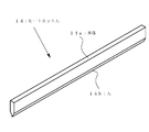
- the heat cut blade is a kind of linear blade, and as shown in FIG. 4, the heat cut blade is cut to a predetermined length in advance according to the use state of the heat cut blade 14 such as the shape and size of the object to be cut. It has the linear main body 14a and the blade 14b formed in the at least one edge of this main body 14a.
- the heat cut blade 14 is formed of a conductive wire material such as nickel chrome alloy or stainless steel. When the heat cut blade 14 is energized, the heat cut blade 14 is heated and the object is melted or pressure bonded. can do.
- such a heat cut blade (linear blade) 14 is generally manufactured by a process as shown in FIG. 5 (a), (b) and (c) schematically show the manufacturing process of the linear blade, and (d) and (e) are cross sections of the respective wires corresponding to (a) and (b).
- (F) is a sectional view of a completed linear cutter.
- a metal wire (round wire 10) that has been cut to a predetermined length in advance according to the usage status of the heat cut blade 14 is prepared, and this round wire 10 is set between the dies 11a and 11b of the press machine. (See FIGS. 5 (a) and 5 (d)).
- a conventional linear cutter such as cutting a round wire, setting to a press machine, pressing, taking out from the press machine, setting to a polishing machine, polishing, taking out from the polishing machine, finishing, etc.
- this process is required, and it takes time for processing and increases the cost.
- processing is performed using a round wire that has been cut to a predetermined length in advance, when an order is received for a linear cutter with a special length exceeding the standard length, processing starts from cutting the round wire. There is also a problem that it takes time from order receipt to shipment.
- the present invention has been made in order to solve the above-mentioned problems all at once, and can continuously manufacture a linear blade, greatly reduce the processing steps, processing time and processing cost, and has a special length. It is an object of the present invention to provide a method for manufacturing a linear cutter capable of immediately responding to the linear cutter, and a roller die apparatus therefor.
- a pair of roller dies for forming a mold hole for processing a wire into a predetermined shape is prepared, and the mold hole forms a blade.
- a cross-sectional shape of the wire rod is formed into a preset shape by passing the wire rod through the mold hole while rotating the roller die, and at the same time, at least one end edge of the wire rod.
- a round wire cut in advance to a predetermined length may be inserted into a die hole of a roller die so as to form a linear cutter having a preset length.
- the wire is continuously supplied from the wire supply unit wound in a roll shape to the mold hole, and the cross-sectional shape of the wire is formed in a preset shape, and at the same time, at least one end edge of the wire After forming the blade, the wire may be cut to a preset length.
- the round wire inserted into the mold hole of the roller die is rolled by a pair of the roller dies rotating in the mold hole and formed into a shape according to the mold hole. It advances not only to the apex part side but also to the opposite side of the apex part. Therefore, as described in claim 3, the roller die having a deformation suppressing portion formed on the opposite side to the apex portion is prepared, and the wire passed through the mold hole is brought into contact with the deformation suppressing portion. And you may make it suppress the deformation
- a roller die is prepared in addition to the roller die, and the rotating edge of the other roller die is inserted into the mold hole so that the wire is placed on the apex portion side. You may make it press on. Furthermore, when forming a deformed material such as a linear cutter, a force acts to shift the pair of roller dies relative to each other in a direction parallel to the rotation axis of the roller dies. By making the plurality of roller dies constituting the mold hole mesh with each other at the cusp, the deviation of the pair of roller dies can be suppressed, and a highly accurate linear blade can be formed. .
- the roller dice apparatus used in the method of the present invention is a roller dice apparatus having a pair of roller dice for forming a mold hole for processing a wire into a predetermined shape as described in claim 6.
- a configuration is provided in which a cusp portion is formed on a part of the mold hole for forming a blade on at least one end edge of the wire rod.
- a deformation suppressing portion that abuts on the wire and suppresses deformation of the wire to the opposite side of the cusp portion is formed.
- roller die in addition to the roller die, another roller die that is inserted into the mold hole and presses the wire rod toward the apex portion may be provided. . Furthermore, as described in claim 9, the plurality of roller dies constituting the mold cavity may be configured to mesh with each other at the apex portion.
- the linear cutter can be continuously manufactured by the roller die, so that the processing steps, processing time and processing cost can be greatly reduced.
- a continuously formed long linear cutter may be cut to a predetermined length according to the application, it is possible to immediately cope with a special length of linear cutter.
- the manufacturing method and roller die apparatus of this invention Polishing and finishing may be performed after forming the linear blade with. Even in such a case, since the highly accurate linear cutter is formed by the manufacturing method and the roller die apparatus of the present invention, there is an advantage that the processing time in these steps can be greatly shortened.
- FIGS. 1 and 2 show various forms of the mold hole in the roller die apparatus of FIG. 1 and FIG. 2 and how each part of the linear blade 14 is formed by the mold hole. It is the elements on larger scale seen from the arrow I direction. It is a perspective view of a heat cut blade according to an example of a linear blade. It is a figure concerning the prior art example of this invention and explaining the manufacturing process of a heat cut blade (linear blade).
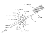
- FIG. 1 is an explanatory view of the main part of a roller die apparatus used in the method for forming a linear blade of the present invention.
- the roller dice apparatus is fed from a pair of roller dies 2 and 2 arranged opposite to each other, a round wire supply unit 1A around which a round wire 1 having a circular cross section as a wire is wound, and a round wire supply unit 1A (not shown). And a guide for guiding the round wire 1 between the roller dies 2 and 2.
- Each of the roller dies 2 and 2 is formed at contact surfaces 2a and 2a that are in contact with each other, and at positions recessed from the contact surfaces 2a and 2a, respectively, and is formed in parallel with the rotation axes C and C of the roller dies 2 and 2.
- the first rolled surface 2b, 2b and the inclined second rolled surface 2c forming the apex portion by connecting the first rolled surface 2b, 2b and the contact surface 2a, 2a. , 2c.
- region enclosed by the 1st rolling surfaces 2b and 2b and the 2nd rolling surfaces 2c and 2c forms the mold hole for shape
- the round wire 1 sent out from the round wire supply unit 1A is continuously passed through the mold hole formed between the pair of roller dies 2 and 2 by the first rolling surfaces 2b and 2b.
- the blade 14b is formed by the second rolling surfaces 2c, 2c.
- the long linear cutter 14 continuously formed in this way is cut into a desired length in a subsequent process as necessary.
- FIG. 2 is an explanatory view of the main part of another embodiment of a roller die apparatus used in the method for forming a linear blade of the present invention.
- the difference from the previous embodiment is that, in the previous embodiment, a long round wire 1 wound is set in the round wire supply unit 1A, whereas the round wire supply of this embodiment is set.
- 1B a round line 1 cut to a preset length is set.
- a plurality of round wires 1 are set in the round wire supply unit 1B of this embodiment, and the round wires 1 fed out one by one are supplied between the roller dies 2 and 2 through a guide (not shown).
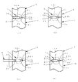
- FIG. 3 shows various forms of the mold hole in the roller die apparatus of FIGS. 1 and 2 and how each part of the linear blade 14 is formed by the mold hole. 1. It is the elements on larger scale seen from the arrow I direction of FIG.
- the round wire 1 introduced between the roller dies 2 and 2 has a plate-like main body 14a formed by the first rolling surfaces 2b and 2b, and the second The rolling surfaces 2c and 2c form a blade 14b at one end edge of the main body 14a.
- the center position of the round wire 1 (the position indicated by the center line C1) is on the opposite side (that is, the left side in the drawing) to the apex (formed by the second rolling surfaces 2c, 2c) of the mold cavity. If it deviates more than a certain amount, the round wire 1 after being crushed does not sufficiently reach the tips of the second rolling surfaces 2c, 2c, and the high-precision blade 14b cannot be formed.
- the center position C1 of the round wire 1 introduced into the mold hole is preferably as close to the second rolling surfaces 2c and 2c as possible within a range in which the linear blade 14 can be formed with high accuracy.
- the roller dies 2 and 2 are provided on the opposite sides of the first rolling surfaces 2b and 2b to the cusp portion and on the entire circumference of the first rolling surfaces 2b and 2b.
- Protrusions 2d and 2d are formed across.
- the protrusions 2d and 2d are for suppressing the progress of the deformation of the round wire 1 toward the anti-apex portion in the mold cavity, and for causing the deformation of the round wire 1 to face the apex portion side efficiently. Therefore, the blade 14b can be formed with high accuracy.
- roller die 4 that rotates in synchronization with the roller dies 2 and 2 is provided.
- the roller die 4 is rotatable around a rotation axis C2 orthogonal to the rotation axes C and C (see FIG. 1) of the roller dies 2 and 2 on the paper surface of FIG. Then, the rotating edge of the roller die 4 is inserted into the mold hole, and the round wire 1 in the mold hole is pushed toward the apex portion by the rotating edge. By doing in this way, the deformation
- a gap may be formed between the protrusions 2d and 2d in FIG. 3B, and the rotation end edge of the roller die 4 may be inserted into this gap.
- the contact surfaces 2a and 2a are formed as surfaces parallel to the rotation axes C and C of the roller dies 2 and 2 (see FIG. 1).
- the contact surfaces are formed as contact surfaces 2a ′ and 2a ′ which are inclined and meshed with the rotation axes C and C in the same direction at the same angle.
- the contact surface 2a' is facilitated. In this manner, the sharp contact angle of the blade 14b can be made more accurate by engaging the inclined contact surfaces 2a 'and 2a' with each other.
- the pair of roller dies 2 and 2 try to shift from each other in the direction parallel to the rotation axes C and C due to the load generated when the round wire 1 is crushed, but the contact surfaces 2a 'and 2a' are engaged with each other. Thus, such an action can be suppressed, and this makes it possible to form the blade 14b with higher accuracy.
- the present invention is not limited to the above description.
- the pair of roller dies 2 and 2 provided in the roller die apparatus is not limited to one set, and a plurality of sets may be provided to form the linear cutter 14 step by step.
- the wire used is described as the circular wire 1 having a circular cross section, in the present invention, wires having other cross sectional shapes such as an elliptical shape, a rectangular shape, and a square shape can also be used.
- a linear cutting tool having blades 14b on both sides of the main body 14a is formed by forming inclined second rolling surfaces 2c, 2c on both sides of the first rolling surfaces 2b, 2b. It is also possible to mold. Further, in the present invention, a process such as polishing and finishing may be added after the main body 14a and the blade 14b are simultaneously formed by a roller die device. However, since the main body 14a and the blade 14b can be formed with high accuracy, the polishing and finishing are performed. There is an advantage that the time required for the process can be greatly shortened.
- the contact surfaces 2a 'and 2a' that are inclined in the same direction and at the same angle are engaged with each other. It is not limited to this. It may have one or a plurality of irregularities. Also in the examples of FIGS. 3A to 3C, one or a plurality of irregularities may be provided on the contact surfaces 2a and 2a in order to suppress deviation.
- the present invention is not limited to heat-cutting blades used for processing / manufacturing of automobile interior materials and the like, and can be widely applied to forming linear blades used for other purposes.
Landscapes
- Engineering & Computer Science (AREA)
- Mechanical Engineering (AREA)
- Life Sciences & Earth Sciences (AREA)
- Agronomy & Crop Science (AREA)
- Forests & Forestry (AREA)
- Forging (AREA)
- Details Of Cutting Devices (AREA)
- Nonmetal Cutting Devices (AREA)
- Wire Processing (AREA)
Priority Applications (1)
| Application Number | Priority Date | Filing Date | Title |
|---|---|---|---|
| US15/564,120 US10589326B2 (en) | 2016-02-12 | 2016-12-19 | Method for manufacturing linear cutter, and roller die device for molding linear cutter |
Applications Claiming Priority (2)
| Application Number | Priority Date | Filing Date | Title |
|---|---|---|---|
| JP2016024353A JP6684605B2 (ja) | 2016-02-12 | 2016-02-12 | 線状刃物の製造方法及び線状刃物成形用のローラダイス装置 |
| JP2016-024353 | 2016-02-12 |
Publications (1)
| Publication Number | Publication Date |
|---|---|
| WO2017138257A1 true WO2017138257A1 (ja) | 2017-08-17 |
Family
ID=59563027
Family Applications (1)
| Application Number | Title | Priority Date | Filing Date |
|---|---|---|---|
| PCT/JP2016/087704 Ceased WO2017138257A1 (ja) | 2016-02-12 | 2016-12-19 | 線状刃物の製造方法及び線状刃物成形用のローラダイス装置 |
Country Status (3)
| Country | Link |
|---|---|
| US (1) | US10589326B2 (enExample) |
| JP (1) | JP6684605B2 (enExample) |
| WO (1) | WO2017138257A1 (enExample) |
Cited By (1)
| Publication number | Priority date | Publication date | Assignee | Title |
|---|---|---|---|---|
| CN110976511A (zh) * | 2019-12-20 | 2020-04-10 | 有研亿金新材料有限公司 | 一种铂银合金超窄薄带材的制备方法 |
Citations (4)
| Publication number | Priority date | Publication date | Assignee | Title |
|---|---|---|---|---|
| US2868042A (en) * | 1956-06-11 | 1959-01-13 | Wallace & Sons Mfg Company R | Method of making a one piece solid handle knife |
| JPS5112371A (en) * | 1974-07-23 | 1976-01-30 | Hokyama Hamono Kk | Hamonono seizoho |
| JPH10225898A (ja) * | 1996-12-09 | 1998-08-25 | Jiemiko:Kk | コーキング材剥離用カッター |
| JP2006075453A (ja) * | 2004-09-13 | 2006-03-23 | Shooei Shoji:Kk | 剃刀及びその製造方法 |
Family Cites Families (6)
| Publication number | Priority date | Publication date | Assignee | Title |
|---|---|---|---|---|
| US2184150A (en) * | 1935-07-31 | 1939-12-19 | Bard Parker Company Inc | Method of making rib-back blades |
| FR2213817B1 (enExample) * | 1973-01-12 | 1975-10-31 | Degrenne Guy | |
| JPH0313243A (ja) * | 1989-06-09 | 1991-01-22 | Kobe Steel Ltd | 異形断面条の成形方法 |
| JP2505610Y2 (ja) | 1990-10-25 | 1996-07-31 | 高島屋日発工業株式会社 | 自動車用内装材の製造装置 |
| JP4742568B2 (ja) | 2004-11-22 | 2011-08-10 | 三菱電機株式会社 | 乗客コンベヤーの移動手摺装置 |
| JP5112371B2 (ja) | 2009-03-27 | 2013-01-09 | 株式会社東芝 | 気流発生装置 |
-
2016
- 2016-02-12 JP JP2016024353A patent/JP6684605B2/ja active Active
- 2016-12-19 US US15/564,120 patent/US10589326B2/en active Active
- 2016-12-19 WO PCT/JP2016/087704 patent/WO2017138257A1/ja not_active Ceased
Patent Citations (4)
| Publication number | Priority date | Publication date | Assignee | Title |
|---|---|---|---|---|
| US2868042A (en) * | 1956-06-11 | 1959-01-13 | Wallace & Sons Mfg Company R | Method of making a one piece solid handle knife |
| JPS5112371A (en) * | 1974-07-23 | 1976-01-30 | Hokyama Hamono Kk | Hamonono seizoho |
| JPH10225898A (ja) * | 1996-12-09 | 1998-08-25 | Jiemiko:Kk | コーキング材剥離用カッター |
| JP2006075453A (ja) * | 2004-09-13 | 2006-03-23 | Shooei Shoji:Kk | 剃刀及びその製造方法 |
Cited By (1)
| Publication number | Priority date | Publication date | Assignee | Title |
|---|---|---|---|---|
| CN110976511A (zh) * | 2019-12-20 | 2020-04-10 | 有研亿金新材料有限公司 | 一种铂银合金超窄薄带材的制备方法 |
Also Published As
| Publication number | Publication date |
|---|---|
| US10589326B2 (en) | 2020-03-17 |
| JP2017140637A (ja) | 2017-08-17 |
| US20180078980A1 (en) | 2018-03-22 |
| JP6684605B2 (ja) | 2020-04-22 |
Similar Documents
| Publication | Publication Date | Title |
|---|---|---|
| JP6810265B2 (ja) | 金属板の切断方法,金属成形体の製造方法及び金属成形体 | |
| CN116766274A (zh) | 剃毛刀片及其制造方法 | |
| JP4071248B2 (ja) | 渦巻きばね成形方法及び成形装置 | |
| JP5801825B2 (ja) | ブランクを絞り加工及びトリミングするための方法及び装置 | |
| WO2017138257A1 (ja) | 線状刃物の製造方法及び線状刃物成形用のローラダイス装置 | |
| JP3648683B2 (ja) | パンチプレスで薄板を厚板に成形する異形材製造方法 | |
| AU2022377026A1 (en) | Method and apparatus for producing a calibrated stamped part | |
| JPH04210831A (ja) | アクスルケース側板の製法 | |
| JP4605517B2 (ja) | 袋ナットの製造方法 | |
| JP4798139B2 (ja) | 鍛造装置および鍛造方法 | |
| JP6640902B2 (ja) | ねじ転造ダイスを冷間成形する方法及び装置 | |
| JP2018051617A (ja) | 熱間鍛造方法 | |
| JP2017140637A5 (enExample) | ||
| CN115256126B (zh) | 金属针布上刀模多刀修磨夹具装置 | |
| CN206445166U (zh) | 一种轨道配件产品温锻与整型模具组 | |
| JP3754911B2 (ja) | タイヤ成形用金型に埋設する三次元ブレード板の製造方法及びその三次元ブレード板の製造用金型 | |
| JP2007015016A (ja) | キャンバ孔を有する金属板を製造する方法 | |
| KR100701464B1 (ko) | 판재절곡방법 | |
| JP2016078059A (ja) | 金属部材の製造方法、金属部材および金型 | |
| WO2025132291A1 (en) | Cold forming a component | |
| CN117718694A (zh) | 一种实心花齿的制作方法 | |
| CN111093853B (zh) | 形成扬声器壳体的方法及相关工具 | |
| JPH0743607U (ja) | 帯刃の曲げ装置におけるせん断装置 | |
| JPH07250844A (ja) | 毛抜き等の板金折曲物品の製造方法 | |
| KR101295252B1 (ko) | 금형을 이용한 에지 성형장치 |
Legal Events
| Date | Code | Title | Description |
|---|---|---|---|
| WWE | Wipo information: entry into national phase |
Ref document number: 15564120 Country of ref document: US |
|
| 121 | Ep: the epo has been informed by wipo that ep was designated in this application |
Ref document number: 16889958 Country of ref document: EP Kind code of ref document: A1 |
|
| NENP | Non-entry into the national phase |
Ref country code: DE |
|
| 122 | Ep: pct application non-entry in european phase |
Ref document number: 16889958 Country of ref document: EP Kind code of ref document: A1 |