WO2017134959A1 - 駆動装置 - Google Patents
駆動装置 Download PDFInfo
- Publication number
- WO2017134959A1 WO2017134959A1 PCT/JP2016/088607 JP2016088607W WO2017134959A1 WO 2017134959 A1 WO2017134959 A1 WO 2017134959A1 JP 2016088607 W JP2016088607 W JP 2016088607W WO 2017134959 A1 WO2017134959 A1 WO 2017134959A1
- Authority
- WO
- WIPO (PCT)
- Prior art keywords
- cover
- lead wire
- housing
- terminal
- drive device
- Prior art date
- Legal status (The legal status is an assumption and is not a legal conclusion. Google has not performed a legal analysis and makes no representation as to the accuracy of the status listed.)
- Ceased
Links
Images


Classifications
-
- H—ELECTRICITY
- H02—GENERATION; CONVERSION OR DISTRIBUTION OF ELECTRIC POWER
- H02K—DYNAMO-ELECTRIC MACHINES
- H02K5/00—Casings; Enclosures; Supports
- H02K5/04—Casings or enclosures characterised by the shape, form or construction thereof
- H02K5/10—Casings or enclosures characterised by the shape, form or construction thereof with arrangements for protection from ingress, e.g. water or fingers
-
- B—PERFORMING OPERATIONS; TRANSPORTING
- B62—LAND VEHICLES FOR TRAVELLING OTHERWISE THAN ON RAILS
- B62D—MOTOR VEHICLES; TRAILERS
- B62D5/00—Power-assisted or power-driven steering
- B62D5/04—Power-assisted or power-driven steering electrical, e.g. using an electric servo-motor connected to, or forming part of, the steering gear
- B62D5/0403—Power-assisted or power-driven steering electrical, e.g. using an electric servo-motor connected to, or forming part of, the steering gear characterised by constructional features, e.g. common housing for motor and gear box
- B62D5/0406—Power-assisted or power-driven steering electrical, e.g. using an electric servo-motor connected to, or forming part of, the steering gear characterised by constructional features, e.g. common housing for motor and gear box including housing for electronic control unit
-
- H—ELECTRICITY
- H02—GENERATION; CONVERSION OR DISTRIBUTION OF ELECTRIC POWER
- H02K—DYNAMO-ELECTRIC MACHINES
- H02K11/00—Structural association of dynamo-electric machines with electric components or with devices for shielding, monitoring or protection
- H02K11/30—Structural association with control circuits or drive circuits
- H02K11/33—Drive circuits, e.g. power electronics
-
- H—ELECTRICITY
- H02—GENERATION; CONVERSION OR DISTRIBUTION OF ELECTRIC POWER
- H02K—DYNAMO-ELECTRIC MACHINES
- H02K5/00—Casings; Enclosures; Supports
- H02K5/04—Casings or enclosures characterised by the shape, form or construction thereof
- H02K5/22—Auxiliary parts of casings not covered by groups H02K5/06-H02K5/20, e.g. shaped to form connection boxes or terminal boxes
- H02K5/225—Terminal boxes or connection arrangements
-
- H—ELECTRICITY
- H02—GENERATION; CONVERSION OR DISTRIBUTION OF ELECTRIC POWER
- H02K—DYNAMO-ELECTRIC MACHINES
- H02K7/00—Arrangements for handling mechanical energy structurally associated with dynamo-electric machines, e.g. structural association with mechanical driving motors or auxiliary dynamo-electric machines
- H02K7/08—Structural association with bearings
- H02K7/083—Structural association with bearings radially supporting the rotary shaft at both ends of the rotor
-
- B—PERFORMING OPERATIONS; TRANSPORTING
- B62—LAND VEHICLES FOR TRAVELLING OTHERWISE THAN ON RAILS
- B62D—MOTOR VEHICLES; TRAILERS
- B62D5/00—Power-assisted or power-driven steering
- B62D5/04—Power-assisted or power-driven steering electrical, e.g. using an electric servo-motor connected to, or forming part of, the steering gear
-
- H—ELECTRICITY
- H02—GENERATION; CONVERSION OR DISTRIBUTION OF ELECTRIC POWER
- H02K—DYNAMO-ELECTRIC MACHINES
- H02K11/00—Structural association of dynamo-electric machines with electric components or with devices for shielding, monitoring or protection
- H02K11/20—Structural association of dynamo-electric machines with electric components or with devices for shielding, monitoring or protection for measuring, monitoring, testing, protecting or switching
- H02K11/21—Devices for sensing speed or position, or actuated thereby
-
- H—ELECTRICITY
- H02—GENERATION; CONVERSION OR DISTRIBUTION OF ELECTRIC POWER
- H02K—DYNAMO-ELECTRIC MACHINES
- H02K2211/00—Specific aspects not provided for in the other groups of this subclass relating to measuring or protective devices or electric components
- H02K2211/03—Machines characterised by circuit boards, e.g. pcb
-
- H—ELECTRICITY
- H02—GENERATION; CONVERSION OR DISTRIBUTION OF ELECTRIC POWER
- H02K—DYNAMO-ELECTRIC MACHINES
- H02K3/00—Details of windings
- H02K3/46—Fastening of windings on the stator or rotor structure
- H02K3/50—Fastening of winding heads, equalising connectors, or connections thereto
Definitions
- the present disclosure relates to a drive device including a motor and a control unit.
- a drive device in which a motor and a control unit for controlling the motor are integrally provided is known.
- a motor housing is provided with a hole (hereinafter referred to as a lead wire insertion hole) through which a lead wire that connects the motor coil and the control unit is passed.
- a lead wire insertion hole communicates the inside and outside of the housing, there is a concern that foreign matter generated when the lead wire and the control unit are electrically connected by, for example, soldering or the like enters the housing through the lead wire insertion hole.
- the drive device disclosed in Patent Document 1 includes a seal member that closes the lead wire insertion hole. The seal member is sandwiched and held between the bottom portion of the bottomed cylindrical case constituting the housing and the frame end.
- the seal member is only necessary for preventing foreign matter from entering the housing when the lead wire and the control unit are connected, and is unnecessary when the drive device is used. Therefore, it is required to reduce the number of seal members in order to improve the assemblability and reduce the number of parts.
- the present disclosure has been made in view of the above-described points, and an object of the present disclosure is to enter a foreign substance into the housing when the lead wire and the control unit are connected without providing a seal member in the lead wire insertion hole of the housing. It is providing the drive device which can suppress this.
- a drive device of the present disclosure is provided in a housing, a stator fixed in the housing, a rotor provided rotatably with respect to the stator, a cover attached to an outer wall of the housing, and the cover. And a control unit for controlling energization of the stator coil, a terminal extending from the control unit, and a lead wire extending from the coil.
- the terminal passes through the cover.
- the lead wire penetrates the housing and the cover, and is electrically connected to the terminal outside the cover.
- the drive device configured as described above can connect the lead wire and the terminal with, for example, solder after the cover is attached to the housing. At this time, when connecting the lead wire and the terminal, the lead wire insertion hole of the housing is blocked by the cover. Therefore, without providing a seal member in the lead wire insertion hole of the housing, it is possible to suppress the entry of foreign matter such as solder scraps generated during soldering or spatter generated during welding into the housing through the lead wire insertion hole. be able to. Since it is not necessary to provide a seal member, it is possible to improve the assembling property and reduce the number of parts.
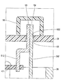
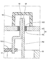
- FIG. 10 A drive device according to a first embodiment of the present disclosure is shown in FIG.
- the drive device 10 is used as a drive source of an electric power steering device that assists the steering of the vehicle driver.
- the drive device 10 is an electromechanical integrated drive device in which a motor 11 and a control unit 12 for controlling the motor 11 are integrally provided.
- the motor 11 is a three-phase brushless motor, and includes a stator 21, a rotor 22, and a housing 23 for housing them.
- the stator 21 has a stator core 24 fixed in the housing 23 and two sets of three-phase coils (hereinafter referred to as coils) 25 assembled to the stator core 24.
- coils three-phase coils
- One lead wire 261, 262, 263 is extended from each phase winding constituting the coil 25.
- lead wire 26 when the lead wires 261, 262, and 263 are not distinguished, they are simply referred to as “lead wire 26”.
- the rotor 22 has a rotating shaft 32 supported by bearings 29 and 31 and a rotor core 33 fitted to the rotating shaft 32.
- the rotor 22 is rotatable with respect to the stator 21 inside the stator 21.
- a detected member 34 made of a permanent magnet is provided at one end of the rotating shaft 32.
- the detected member 34 is used by a rotation angle sensor 42 described later to detect the rotation angle of the rotor 22.
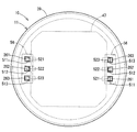
- the housing 23 includes a cylindrical case 35, a first frame end 36 provided at one end of the case 35, and a second frame end 37 provided at the other end of the case 35.
- the first frame end 36 and the second frame end 37 sandwich the case 35 and are fastened to each other by a plurality of bolts (not shown).
- the bearing 29 is provided at the center of the first frame end 36, and the bearing 31 is provided at the center of the second frame end 37.
- the first frame end 36 has a lead wire insertion hole 38 through which the lead wire 26 is inserted. In the present embodiment, the lead wire insertion hole 38 is provided for each lead wire 26.
- a cover 39 is attached to the outer wall of the housing 23 and on the wall of the first frame engine 36 on the control unit 12 side.
- the cover 39 has a cup shape. The cover 39 protects the control unit 12 from external impacts and prevents entry of dust, water, and the like into the control unit 12.
- the control unit 12 includes various electronic components 41 to 46 and a substrate 47 on which they are mounted.
- the substrate 47 is, for example, a printed circuit board, and is provided to face the first frame end 36. Of the two main surfaces of the substrate 47, the surface facing the first frame end 36 is a first main surface 48, and the opposite surface is a second main surface 49.
- the first main surface 48 of the substrate 47 includes a plurality of switching elements 41 that constitute inverters corresponding to the two systems of coils 25, a rotation angle sensor 42 that detects the position of the rotor 22, and the switching elements 41.
- an integrated circuit 43 that outputs a drive signal is mounted.
- the rotation angle sensor 42 faces the detected member 34.
- the switching element 41 and the integrated circuit 43 are in contact with the first frame end 36 in a state where heat can be radiated through a heat radiating gel (not shown).
- the first frame end 36 also functions as a heat sink.
- a microcomputer 44 that calculates a command value for the power supplied to each phase winding of the coil 13 based on the position of the rotor 22 and the like, power supply to the inverter by storing electric charge And a choke coil 46 constituting a filter circuit together with the capacitor 45 are mounted.
- Terminals 511, 512, and 513 extend from the substrate 47 one by one corresponding to the lead wires 261, 262, and 263, respectively.
- terminal 51 When the terminals 511, 512, and 513 are not distinguished, they are simply referred to as “terminal 51”.
- the terminal 51 is electrically connected to the lead wire 26 and the substrate 47 by soldering. Detailed configurations of the lead wire 26 and the terminal 51 will be described later.
- the drive device 10 configured in this manner rotates the rotor 22 by sequentially switching energization to the respective phase windings of the coil 25 based on the detection signal of the rotation angle sensor 42 to generate a rotating magnetic field.
- the controller 12 of the driving device 10 is mounted on one side in the axial direction with respect to the motor 11. Therefore, it can be avoided that the control unit 12 directly receives the vibration of the motor 11.
- the first frame end 36 to which the control unit 12 is fixed is made of, for example, aluminum die casting and is precisely formed. Therefore, the positional accuracy between the control unit 12 and the motor 11 is significantly improved, and the heat generated by the control unit 12 can be effectively released.
- Each phase winding of the coil 25 and the substrate 47 are connected to each other via the lead wire 26 and the terminal 51.
- the first phase winding of the coil 25 is connected to the substrate 47 via the lead wire 261 and the terminal 511.
- the second phase winding of the coil 25 is connected to the substrate 47 via the lead wire 262 and the terminal 512.
- the third phase winding of the coil 25 is connected to the substrate 47 via the lead wire 263 and the terminal 513.
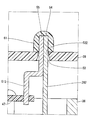
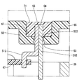
- the lead wire 26 penetrates the first frame end 36 and the cover 39.
- the terminal 51 passes through the cover 39.
- the cover 39 has a through hole 521 through which the lead wire 261 and the terminal 511 are inserted, a through hole 522 through which the lead wire 262 and the terminal 512 are inserted, and a through hole 523 through which the lead wire 263 and the terminal 513 are inserted. have.
- through holes 52 Of the inner wall surface of the through hole 52, the control unit 12 side is a tapered surface 53 having an inner diameter that is larger toward the control unit 12 side.
- the one end 54 of the lead wire 26 and the one end 55 of the terminal 51 protrude outside the cover 39, and are electrically connected to each other by soldering outside the cover 39.
- the driving apparatus 10 further includes a shielding member 56 provided on the outer wall of the cover 39 so as to shield the lead wire 26 and the terminal 51 from the external space.
- the shielding member 56 is indicated by a two-dot chain line for convenience.
- the shielding member 56 has a cup shape, and the opening end portion is fixed to the cover 39 by, for example, bonding or the like while covering the one end 54 of the lead wire 26 and the one end 55 of the terminal 51.
- the drive device 10 configured as described above is assembled in the following procedures (1) to (6).
- (1) The stator 21 and the rotor 22 are assembled to the housing 23.
- the lead wire 26 is provided so as to protrude from the first frame end 36 to the outside of the housing 23.
- (2) The electronic components 41 to 46 and the terminal 51 are mounted on the substrate 47.
- (3) The substrate 47 is fixed to the first frame end 36.
- (4) The cover 39 is attached to the first frame end 36.
- the lead wire 26 and the terminal 51 are inserted into the through hole 52 of the cover 39, and the opening end portion of the cover 39 is combined and fixed to the first frame end 36.
- the tapered surface 53 functions as a guide portion that guides the lead wire 26 and the terminal 51 to the through hole 52.
- One end 54 of the lead wire 26 and one end 55 of the terminal 51 are electrically connected to each other by soldering outside the cover 39. At this time, soldering is performed in a state where a gap between the lead wire 26 and the through hole 52 is closed by a lid-like jig (not shown). (6) The shielding member 56 is fixed to the cover 39.
- the driving apparatus 10 includes the housing 23, the stator 21 fixed in the housing 23, the rotor 22 provided to be rotatable with respect to the stator 21, and the housing. 23, a cover 39 attached to the outer wall 23, a control unit 12 that is provided in the cover 39, controls the energization of the coil 25 of the stator 21, and extends from the control unit 12, and passes through the cover 39. And a lead wire 26 that extends from the coil 25, penetrates the housing 23, penetrates the cover 39, and is electrically connected to the terminal 51 outside the cover 39.
- the drive device 10 configured in this manner can connect the lead wire 26 and the terminal 51 with, for example, solder after the cover 39 is attached to the housing 23.
- the lead wire insertion hole 38 of the housing 23 is blocked by the cover 39 when the lead wire 26 and the terminal 51 are connected. Accordingly, it is possible to suppress the entry of the solder scrap generated when soldering into the housing 23 through the lead wire insertion hole 38 without providing a seal member in the lead wire insertion hole 38 of the housing 23. Since it is not necessary to provide a seal member, it is possible to improve the assembling property and reduce the number of parts. Since it is not necessary to provide a seal member in the lead wire insertion hole 38, it is possible to improve the assembling property and reduce the number of parts.
- the shielding member 61 is made of resin fused to one end 54 of the lead wire 26 and one end 55 of the terminal 51. That is, the shielding member 61 is a resin that has solidified after adhering to the one ends 54 and 55 in a molten state.
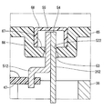
- the cover 65 includes a recess 66 that is recessed toward the inside of the cover 65.
- the through hole 52 is formed at the bottom of the recess 66.
- One end 54 of the lead wire 26 outside the cover 65 and one end 55 of the terminal 51 outside the cover 65 are accommodated in the recess 67 of the recess 66. That is, the one ends 54 and 55 do not protrude outward from the recess 67 of the recess 66.
- a shielding member 68 is fitted in the recess 66.
- the lead wire 26 and the terminal 51 can be connected outside the cover 65 without providing a projection on the cover 65. .
- the shielding member 71 is provided in the recess 67 of the recess 66 and is made of resin fused to one end 54 of the lead wire 26 and one end 55 of the terminal 51. Become.
- the through hole 76 of the cover 75 is formed to have substantially the same size as a combination of one end 54 of the lead wire 26 and one end 55 of the terminal 51. Yes. Therefore, when soldering the lead wire 26 and the terminal 51, it is not necessary to close the through hole 76 using a jig.
- the cover 81 is integrated with a cover main body portion 82 having a through hole 52 through which the lead wire 26 and the terminal 51 are inserted, and an inner wall surface of the through hole 52. And has an elastic portion 83 in contact with the lead wire 26 and the terminal 51 so as to close the gap of the through hole 52.
- the cover body 82 is made of metal.
- the elastic portion 83 is made of a material having a relatively large elasticity, such as rubber.
- the elastic part 83 which closes the gap between the through hole 52 and the lead wire 26 and the terminal 51 is provided, when the lead wire 26 and the terminal 51 are soldered, the through hole 52 is formed using a jig. There is no need to close it.
- the cover main body portion 82 can be made of metal, so that the strength of the cover 81 can be increased and the heat dissipation can be increased.
- one lead wire insertion hole of the housing may be provided for a plurality of lead wires.
- one cover through hole may be provided for a plurality of lead wires.
- the cross-sectional shape of the through hole of the cover is not limited to a rectangle, and may be, for example, a circle.
- the inner wall surface of the through hole of the cover may not have a tapered surface.
- the entire inner wall surface of the through hole of the cover may be a tapered surface.
- the lead wire and the terminal may overlap in the circumferential direction, or may overlap in another direction.
- the fixing method of the shielding member is not limited to adhesion, and other methods such as screw fastening or fitting may be used.
- the motor three-phase coil may be one set or three or more sets.
- the drive device may be applied to devices other than the electric power steering device.
Landscapes
- Engineering & Computer Science (AREA)
- Power Engineering (AREA)
- Microelectronics & Electronic Packaging (AREA)
- Chemical & Material Sciences (AREA)
- Combustion & Propulsion (AREA)
- Transportation (AREA)
- Mechanical Engineering (AREA)
- Motor Or Generator Frames (AREA)
- Windings For Motors And Generators (AREA)
Priority Applications (1)
| Application Number | Priority Date | Filing Date | Title |
|---|---|---|---|
| US16/073,892 US11050318B2 (en) | 2016-02-01 | 2016-12-26 | Drive device |
Applications Claiming Priority (2)
| Application Number | Priority Date | Filing Date | Title |
|---|---|---|---|
| JP2016-016925 | 2016-02-01 | ||
| JP2016016925A JP6520739B2 (ja) | 2016-02-01 | 2016-02-01 | 駆動装置 |
Publications (1)
| Publication Number | Publication Date |
|---|---|
| WO2017134959A1 true WO2017134959A1 (ja) | 2017-08-10 |
Family
ID=59500314
Family Applications (1)
| Application Number | Title | Priority Date | Filing Date |
|---|---|---|---|
| PCT/JP2016/088607 Ceased WO2017134959A1 (ja) | 2016-02-01 | 2016-12-26 | 駆動装置 |
Country Status (3)
| Country | Link |
|---|---|
| US (1) | US11050318B2 (enExample) |
| JP (1) | JP6520739B2 (enExample) |
| WO (1) | WO2017134959A1 (enExample) |
Cited By (2)
| Publication number | Priority date | Publication date | Assignee | Title |
|---|---|---|---|---|
| CN110233544A (zh) * | 2018-03-06 | 2019-09-13 | 本田技研工业株式会社 | 旋转电机 |
| US11996751B2 (en) | 2018-09-20 | 2024-05-28 | Mahle Electric Drives Japan Corporation | Electric motor |
Families Citing this family (10)
| Publication number | Priority date | Publication date | Assignee | Title |
|---|---|---|---|---|
| US10256758B2 (en) * | 2014-11-26 | 2019-04-09 | Kohler Co. | Printed circuit board based exciter |
| DE102016214032A1 (de) * | 2016-07-29 | 2018-02-01 | Volkswagen Aktiengesellschaft | Verfahren zur Herstellung eines Elektromotors und Elektromotor |
| JP7024320B2 (ja) * | 2016-11-07 | 2022-02-24 | 株式会社デンソー | モータ |
| JP6879870B2 (ja) * | 2017-09-07 | 2021-06-02 | 日立Astemo株式会社 | 電動駆動装置及び電動パワーステアリング装置 |
| KR102027396B1 (ko) * | 2018-03-05 | 2019-11-15 | 계양전기 주식회사 | 전자제어모듈 일체형 모터조립체 |
| JP7392599B2 (ja) | 2020-07-14 | 2023-12-06 | 株式会社デンソー | 回転電機 |
| CN115037090A (zh) * | 2021-03-04 | 2022-09-09 | 浙江三花汽车零部件有限公司 | 驱动装置及其制造方法 |
| JP2023051602A (ja) | 2021-09-30 | 2023-04-11 | 日本電産株式会社 | モータ |
| JP2023051603A (ja) | 2021-09-30 | 2023-04-11 | 日本電産株式会社 | モータ |
| US12323035B2 (en) * | 2021-09-30 | 2025-06-03 | Nidec Corporation | Motor |
Citations (4)
| Publication number | Priority date | Publication date | Assignee | Title |
|---|---|---|---|---|
| JP2010263768A (ja) * | 2009-04-09 | 2010-11-18 | Nsk Ltd | 電動パワーステアリング装置 |
| JP2014138489A (ja) * | 2013-01-17 | 2014-07-28 | Nissan Motor Co Ltd | インバータ付きモータ |
| JP2015154673A (ja) * | 2014-02-18 | 2015-08-24 | 株式会社デンソー | 回転電機 |
| JP2016019335A (ja) * | 2014-07-07 | 2016-02-01 | 日本精工株式会社 | 電動モータとその制御装置との接合構造及び接合方法、並びに、これを用いたアクチュエータ、電動パワーステアリング装置、及び、車両 |
Family Cites Families (2)
| Publication number | Priority date | Publication date | Assignee | Title |
|---|---|---|---|---|
| JP2010041871A (ja) | 2008-08-07 | 2010-02-18 | Mitsuba Corp | ブラシレスモータ |
| JP6011557B2 (ja) | 2014-01-31 | 2016-10-19 | 株式会社デンソー | 駆動装置 |
-
2016
- 2016-02-01 JP JP2016016925A patent/JP6520739B2/ja active Active
- 2016-12-26 WO PCT/JP2016/088607 patent/WO2017134959A1/ja not_active Ceased
- 2016-12-26 US US16/073,892 patent/US11050318B2/en active Active
Patent Citations (4)
| Publication number | Priority date | Publication date | Assignee | Title |
|---|---|---|---|---|
| JP2010263768A (ja) * | 2009-04-09 | 2010-11-18 | Nsk Ltd | 電動パワーステアリング装置 |
| JP2014138489A (ja) * | 2013-01-17 | 2014-07-28 | Nissan Motor Co Ltd | インバータ付きモータ |
| JP2015154673A (ja) * | 2014-02-18 | 2015-08-24 | 株式会社デンソー | 回転電機 |
| JP2016019335A (ja) * | 2014-07-07 | 2016-02-01 | 日本精工株式会社 | 電動モータとその制御装置との接合構造及び接合方法、並びに、これを用いたアクチュエータ、電動パワーステアリング装置、及び、車両 |
Cited By (2)
| Publication number | Priority date | Publication date | Assignee | Title |
|---|---|---|---|---|
| CN110233544A (zh) * | 2018-03-06 | 2019-09-13 | 本田技研工业株式会社 | 旋转电机 |
| US11996751B2 (en) | 2018-09-20 | 2024-05-28 | Mahle Electric Drives Japan Corporation | Electric motor |
Also Published As
| Publication number | Publication date |
|---|---|
| US11050318B2 (en) | 2021-06-29 |
| JP6520739B2 (ja) | 2019-05-29 |
| US20190044406A1 (en) | 2019-02-07 |
| JP2017139830A (ja) | 2017-08-10 |
Similar Documents
| Publication | Publication Date | Title |
|---|---|---|
| WO2017134959A1 (ja) | 駆動装置 | |
| JP5063722B2 (ja) | 電動式駆動装置およびそれを搭載した電動式パワーステアリング装置 | |
| JP5748917B2 (ja) | 電動式駆動装置および電動式駆動装置の製造方法 | |
| JP3638269B2 (ja) | 電動式パワーステアリング装置 | |
| CN111845921B (zh) | 电动驱动装置 | |
| JP5764459B2 (ja) | 駆動装置 | |
| US7445081B2 (en) | Electric power steering apparatus | |
| JP5927836B2 (ja) | 駆動装置 | |
| JP5634610B2 (ja) | 電動式駆動装置 | |
| CN111717274B (zh) | 电动驱动装置 | |
| JP6702212B2 (ja) | 駆動装置 | |
| US20140035445A1 (en) | Rotating electric machine and electric power steering apparatus | |
| JP4252486B2 (ja) | 電動式パワーステアリング装置 | |
| JP6514136B2 (ja) | 電動駆動装置及び電動パワーステアリング装置 | |
| JP4203055B2 (ja) | 電動式パワーステアリング装置 | |
| CN107921998A (zh) | 电动驱动装置及电动助力转向装置 | |
| CN107921996A (zh) | 电动驱动装置及电动助力转向装置 | |
| JP6736904B2 (ja) | 駆動装置 | |
| JP6870711B2 (ja) | 駆動装置、および、これを用いた電動パワーステアリング装置 | |
| CN111727545B (zh) | 电子控制装置以及电动驱动装置 | |
| KR20200108051A (ko) | 전동 구동 장치 및 전동 파워 스티어링 장치 |
Legal Events
| Date | Code | Title | Description |
|---|---|---|---|
| 121 | Ep: the epo has been informed by wipo that ep was designated in this application |
Ref document number: 16889442 Country of ref document: EP Kind code of ref document: A1 |
|
| NENP | Non-entry into the national phase |
Ref country code: DE |
|
| 122 | Ep: pct application non-entry in european phase |
Ref document number: 16889442 Country of ref document: EP Kind code of ref document: A1 |